

Sony FD TRINITRON KV-29FX66E, FD TRINITRON KV-29FX66K, KV-29FX66E, KV-29FX66K Service Manual
- 1 -
SERVICE MANUAL
AE-6B
CHASSIS
MODEL COMMANDER DEST CHASSIS NO.
KV-29FX66E RM-934 ESP SCC-Q81B-A
MODEL COMMANDER DEST CHASSIS NO.
KV-29FX66K RM-934 OIRT SCC-Q82A-A
KV-29FX66
RM-934

- 2 -
TABLE OF CONTENTS
Section Title Page Section Title Page
Specifications .................... 3
Connectors .................... 4
Self Diagnostic Software .................... 5
1. GENERAL
Switching On the TV and
Automatically Tuning .................... 6
Introducing the Menu System .................... 7
Menu Guide .................... 7
T elete xt .................... 9
Remote Control Configuration
for VCR/DVD .................... 9
Specifications .................... 10
Troubleshooting .................... 10
2. DISASSEMBLY
2-1. Rear Cover Removal .................... 11
2-2. Speaker Disconnection .................... 11
2-3. Chassis Removal .................... 11
2-4. Service Position .................... 12
2-5. D and G Board Removal .................... 12
2-6. F4 Bracket Removal .................... 12
2-7. F4 and H1 Board Removal .................... 12
2-8. Side Control Module Removal .................... 13
2-9. H2 Board Removal .................... 13
2-10. M Board Removal .................... 13
2-11. Service Connector for M Board.................... 13
2-12. Picture Tube Removal .................... 14
3. SET-UP ADJUSTMENTS
3-1. Beam Landing .................... 16
3-2. Convergence .................... 17
3-3. Focus Adjustment .................... 19
3-4. Screen (G2), White Balance .................... 19
4. CIRCUIT ADJUSTMENTS
4-1. Electrical Adjustments .................... 20
4-2. T est Mode 2 .................... 22
5. DIAGRAMS
5-1. Block Diagrams (1) .................... 23
Block Diagrams (2) .................... 24
Block Diagrams (3) .................... 25
Block Diagrams (4) .................... 26
5-2. Circuit Board Location .................... 26
5-3. Schematic Diagrams and
Printed Wiring Boards .................... 26
* A Board Schematic .................... 27
* A Board PWB .................... 29
* VM Board Schematic.................... 33
* VM Board PWB .................... 31
* H1 Board Schematic .................... 33
* H1 Board PWB .................... 34
* F4 Board Schematic .................... 33
* F4 Board PWB .................... 34
* H2 Board Schematic .................... 33
* H2 Board PWB .................... 34
* G Board Schematic .................... 35
* G Board PWB .................... 34
* D Board Schematic .................... 36
* D Board PWB .................... 37
* C Board Schematic .................... 38
* C Board PWB .................... 39
* M Board Schematic .................... 40
* M Board PWB .................... 39
5-4. Semiconductors .................... 41
5-5. IC Blocks .................... 44
6. EXPLODED VIEWS
6-1. Chassis .................... 46
6-2. Picture Tube .................... 47
7. ELECTRICAL PARTS LIST .................... 48
CAUTION
SHORT CIRCUIT THE ANODE OF THE PICTURE TUBE AND THE
ANODE CAP TO THE METAL CHASSIS, CRT SHIELD, OR THE
CARBON PAINTED ON THE CRT, AFTER REMOVAL OF THE
ANODE CAP.
WARNING !!
AN ISOLATION TRANSFORMER SHOULD BE USED DURING
ANY SERVICE WORK TO AVOID POSSIBLE SHOCK HAZARD
DUE TO LIVE CHASSIS, THE CHASSIS OF THIS RECEIVER IS
DIRECTLY CONNECTED TO THE POWER LINE.
SAFETY-RELATED COMPONENT WARNING !!
COMPONENTS IDENTIFIED BY SHADING AND MARKED ON
THE SCHEMATIC DIAGRAMS, EXPLODED VIEWS AND IN THE
PARTS LIST ARE CRITICAL FOR SAFE OPERATION. REPLACE
THESE COMPONENTS WITH SONY PARTS WHOSE PART
NUMBERS APPEAR AS SHOWN IN THIS MANUAL OR IN
SUPPLEMENTS PUBLISHED BY SONY.
ATTENTION
APRES AVOIR DECONNECTE LE CAP DE’LANODE,
COURT-CIRCUITER L’ANODE DU TUBE CATHODIQUE ET
CELUI DE L’ANODE DU CAP AU CHASSIS METALLIQUE DE
L’APPAREIL, OU AU COUCHE DE CARBONE PEINTE SUR LE
TUBE CATHODIQUE OU AU BLINDAGE DU TUBE
CATHODIQUE.
ATTENTION !!
AFIN D’EVITER TOUT RISQUE D’ELECTROCUTION
PROVENANT D’UN CHÁSSIS SOUS TENTION, UN
TRANSFORMATEUR D’ISOLEMENT DOIT ETRE UTILISÈ LORS
DE TOUT DÈPANNAGE LE CHÁSSIS DE CE RÈCEPTEUR EST
DIRECTMENT RACCORDÈ Á L’ALIMENTATION SECTEUR.
ATTENTION AUX COMPOSANTS RELATIFS Á
LA SECURITÈ!!
LES COMPOSANTS IDENTIFIÈS PAR UNE TRAME ET PAR UNE
MARQUE SUR LES SCHÈMAS DE PRINCIPE, LES VUES
EXPLOSÈES ET LES LISTES DE PIECES SONT D’UNE IMPOR-
TANCE CRITIQUE POUR LA SÈCURITÈ DU FONCTIONNEMENT,
NE LES REMPLACER QUE PAR DES COMPSANTS SONY DONT
LE NUMÈRO DE PIÈCE EST INDIQUÈ DANS LE PRÈSENT
MANUEL OU DANS DES SUPPLÈMENTS PUBLIÈS PAR SONY.
- 3 -
ebuTerutciP
nortinirTDF
)sehcni92(mc27xorppA
derusaemerutcipmc86xorppA(
)yllanogaid
noitcelfedeerged401
tuptuOdnuoS
rekaepstfeLdnathgiR
refoowbuS
)SMR(W01x2)rewoPcisuM(W02x2
)SMR(W51x1)rewoPcisuM(W03x1
]RAER[slanimreTtuptuO/tupnI snoitacificepSlareneG
rotcennocoruEnip-12:1
)dradnatsCELENEC(
.slangisoediVdnaoiduArofstupnI
.BGRrofstupnI
oiduAdnaoediVVTfostuptuO
.slangis
stnemeriuqeRrewoPV042-022
noitpmusnoCrewoPW031
rotcennocoruEnip-12:2
.slangisoediVdnaoiduArofstupnI
.oediVSrofstupnI
.slangisoiduAdnaoediVVTfostuptuO
)elbatceles(
snoisnemiDmm605x585x177xorppA
thgieWgk05xorppA
rotcennocoruEnip-12:3
.slangisoediVdnaoiduArofstupnI
.oediVSrofstupnI
slangisoiduAdnaoediVrofstuptuO
)tuorotinom(
seirosseccAdeilppuS
)1(rednammoCetomeR439-MR
)2(yrettab6RdetangisedCEI
skcaJonohPoiduArofelbairavsrotcennoCtuptuO
slangiS
serutaeFrehtO
,noitcetedotuAmetsysVT,erutcipzH001
ybloDlautriV,PIP,EBB,kniltramS,txeteleT
]EDIS[slanimreTtuptuO/tupnI lortnocderarfnI:metsyslortnocetomeR
kcajenohpdaeHkcajinimoerets
stnemeriuqerrewoP
cdV3
noitangisedCEIseirettab2
)AAezis(6R
stupnioiduAskcajonohp
stupnioediVskcajonohp
tupnioediVSNIDnip4
.ecitontuohtiwegnahcottcejbuserasnoitacificepsdnangiseD
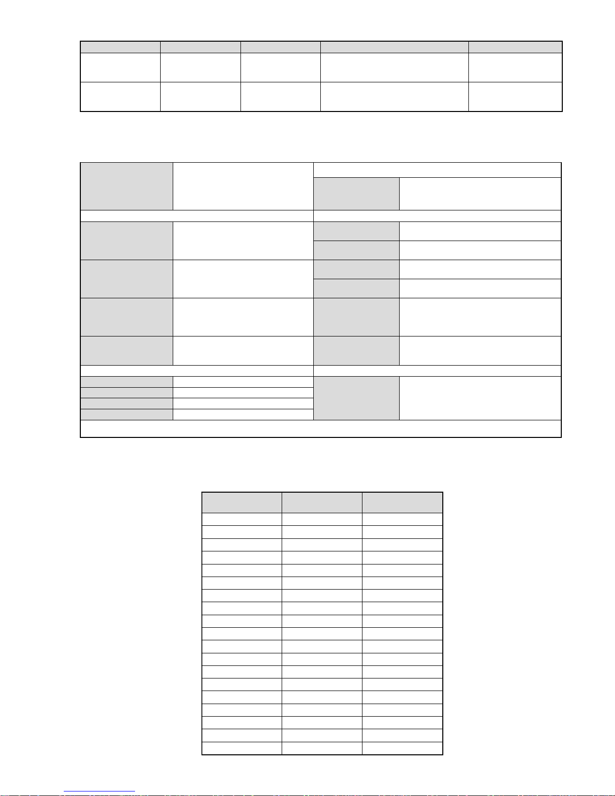
emaNledoM
metI
E66XF92-VK K66XF92-VK
bmoClaPFFOFFO
PIPNONO
ytiroirPBGRNONO
xoBrefooWNONO
1tracSNONO
2tracSNONO
3tracSNONO
)4(nitnorFNONO
rotcejorPFFOFFO
edom9:61niBKANONO
G/BmroNNONO
ImroNFFOFFO
K/DmroNFFONO
SUAmroNFFOFFO
LmroNFFOFFO
TASmroNFFOFFO
MmroNFFOFFO
txeteleTNONO
oeretSmaciNNONO
LEDOMMETI metsySnoisiveleT metsySoeretS egarevoClennahC metsySroloC
EH/G/B
MACIN/NAMREG
oeretS
21E-2E:FHV
96E-12E:FHU
02S-1S,30S-10S:VTELBAC
MACES,LAP
85.3CSTN,34.4CSTN
)NIOEDIV(
KK/D,H/G/B
MACIN/NAMREG
oeretS
21R-10R,21E-2E:FHV
96R-12R,96E-12E:FHU
02S-1S,30S-10S:VTELBAC
MACES,LAP
85.3CSTN,34.4CSTN
)NIOEDIV(
- 4 -
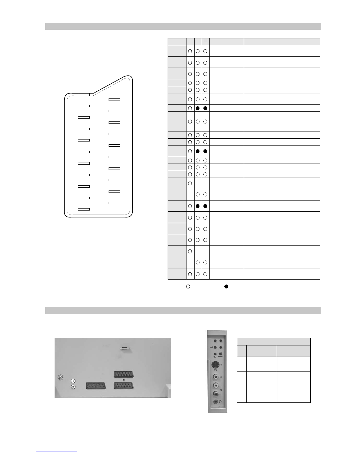
21 pin connector
Connected Not Connected (open) * at 20Hz - 20kHz
Pin No 1 2 4 Signal Signal level
1 Audio output B
(right)
Standard level : 0.5V rms
Output impedence : Less than 1kohm*
2
Audio output B
(right)
Standard level : 0.5V rms
Output impedence : More than 10kohm*
3
Audio output A
(left)
Standard level : 0.5V rms
Output impedence : Less than 1kohm*
4 Ground (audio)
5 Ground (blue)
6 Audio input A
(left)
Standard level : 0.5V rms
Output impedence : More than 10kohm*
7 Blue input 0.7 +/- 3dB, 75 ohms positive
8 Function select
(AV control)
High state (9.5-12V) : Part mode
Low state (0-2V) : TV mode
Input impedence : More than 10K ohms
Input capacitance : Less than 2nF
9 Ground (green)
10 Open
11 Green Green signal : 0.7 +/- 3dB, 75 ohms,
positive
12 Open
13 Ground (re d)
14 Ground (blanking)
15
_ _ Red input 0.7 +/- 3dB, 75 ohms, positive
_ (S signal Chroma
input)
0.3 +/- 3dB, 75 ohms, positive
16 Blanking input
(Ys signal)
High state (1-3V) Low state (0-0.4V)
Input impedence : 75 ohms
17 Ground (video
output)
18 Ground (video
input)
19 Video output 1V +/- 3dB, 75ohms, positive sync 0.3V
(-3+10dB)
20
_ _ Video input 1V +/- 3dB, 75ohms, positive sync 0.3V
(-3+10dB)
_ Video input
Y (S signal)
1V +/- 3dB, 75ohms, positive sync 0.3V
(-3+10dB)
21 Common ground
(plug, shield)
19
17
15
13
11
9
7
5
3
1
20
18
16
14
12
10
8
6
4
2
21
Rear Connection Panel Front Connection Panel
p
- +
4
MONO
4
L/G/S/I
R/D/D/D
s
4
noitarugifnocniptekcosoediVS
niP
oN
langiS leveLlangiS
1dnuorG2dnuorG3tupni)langisS(Y,mho57Bd3-/+V1
V3.0.cnySevitisop
Bd01+3-
4tupni)langisS(CBd3-/+V3.0
evitisop,mho57
.cnyS
S-Video
socket
3
- 5 -
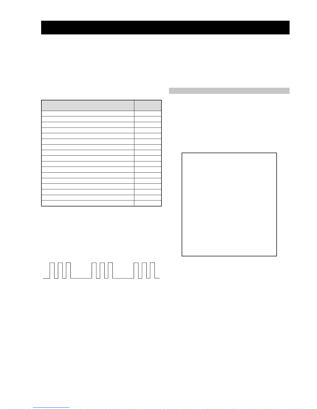
egasseMrorrE
DEL
edoC
rorreoN00
devreseR10
)noitcetorPtnerruCrevO(PCO20
noitcetorPegatloVrevO30
cnySlacitreVoN40
norewoptarorrERKI50
norewoptawolsenilatadro/dnakcolcsubCII60
norewoptaegdelwonkcasubCIIonMVN70
noitcetorPlatnoziroH80
norewoptaegdelwonkcaonrenuT90
rorrErossecorPdnuoS01
devreseR11
rorrEetarnacS21
rorrECAD31
rorrEdnekcaB41
rorrEecnegrevnoCcimanyD51
rorrEPIP61
AE-6B SELF DIAGNOSTIC SOFTWARE
The identification of errors within the AE-6B chassis is triggered in one of two ways :- 1: Busy or 2: De vice failure to respond to IIC. In the
event of one of these situations arising the software will first try to release the bus if busy (Failure to do so will report with a continuous
flashing LED) and then communicate with each device in turn to establish if a device is f aulty . If a device is found to be faulty the rele v ant
device number will be displayed through the LED (Series of flashes which must be counted) See table 1., non fatal errors are reported using this
method.
Each time the software detects an error it is stored within the NVM. See T able 2.
Table 1
How to enter into Ta ble 2
1. T urn on the main po wer switch of the TV set.
2. Program Remote Commander for Operation in Service
Mode. [See Page 20].
2. Press ‘VIDEO’ ‘VIDEO’ > ‘MENU’ > ERROR MENU
on the Remote Commander.
3. The following table will be displayed indicating the error
count.
Table 2
Note: T o clear the error count data press ‘80’ on the Remote
commander.
UNEMRORRE
20E
30E
40E
50E
60E
70E
80E
90E
01E
11E
21E
31E
41E
51E
61E
EMITGNIKROW
SRUOH
SETUNIM
PCO
PVO
CNYSV
RKI
CII
MVN
TORPH
RENUT
PDNUOS
ETARNACS
CAD
DNEKCAB
NOCNYD
PIP
)552,0(
)552,0(
)552,0(
)552,0(
)552,0(
)552,0(
)552,0(
)552,0(
)552,0(
)552,0(
)552,0(
)552,0(
)552,0(
)552,0(
)552,0(
0
0
0
0
0
0
0
0
0
0
0
0
0
0
0
41
7
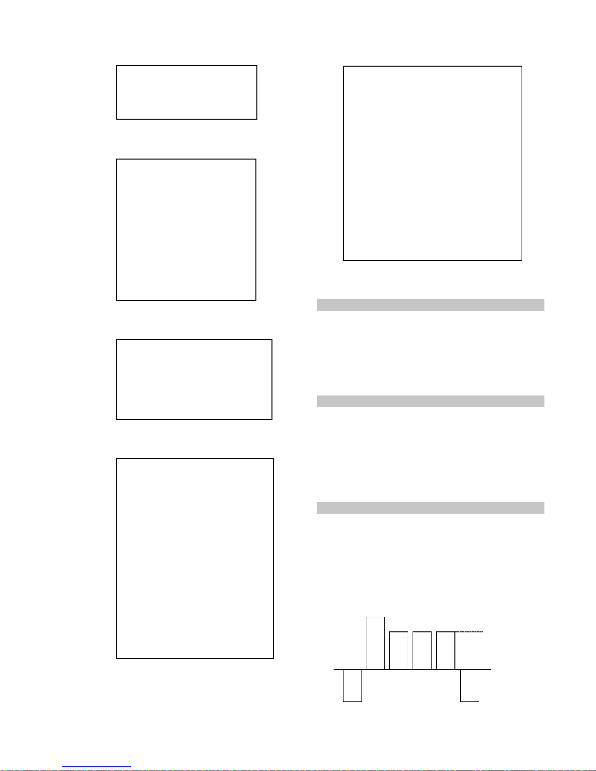
Flash Timing Example : e.g. error number 3
StBy LED
ON
ON ON
OFF
OFF
- 20 -
4-1. Electrical Adjustments
Service adjustments to this model can be performed using the
supplied remote Commander RM-934.
SECTION 4 CIRCUIT ADJUSTMENTS
3. Press 99999. All three LED’s should light.
The remote commander is now set to Service Mode.
4. T o return the remote commander to normal operation mode
repeat steps 1. and 2. then press 00000. All three LED’s
should light.
The remote commander is now set to normal mode.
Programming the Remote Commander for
Operation in Service Mode
Setting the TV into Service Mode
1. Program the remote commander for operation in Service
Mode as described above.
2. Turn on the TV main power switch.
3. Press the video standby button on the remote
commander twice.
‘TT ’ will appear in the upper right corner of the screen.
Other status information will also be displayed.
4. Press ‘MENU’ on the remote commander to obtain the
following menu on the screen.
5. Move to the corresponding adjustment item using the
up or down arrow b uttons on the Remote Commander .
6. Press the right arrow button to enter into the required menu item.
7. Press the ‘Menu’ button on the Remote Commander to quit the
Service Mode when all adjustments have been completed.
Note :
· After carrying out the service adjustments, to prevent the
customer accessing the ‘Service Menu’ switch the TV set
OFF and then ON.
·
yrtemoeG
ecivreS
etarnacS
CAD
.vnoC.nyD
PiP
dnuoS
tsujdaFI
uneMrorrE
)1002nuJ(41.0vB6EA
hFFhFFatadyrotcaF
G1143PSM:eciveDPSM
YRTEMOEG
HTLBA
EDOMLBA
LBAP
EZISV
NOITISOPV
PMOCV
NILV
NOITCERROCS
EZISH
PMANIP
NIPRENROCPU
NIPM
NIPRENROCOL
MUIZEPART
NOITISOPH
WOBCFA
ELGNACFA
KLBTFEL
KLBTHGIR
TCEPSAV
1MITBKA
2MITBKA
RKI
GNH
GNV
)3,0(
)3,0(
)51,0(
)36,0(
)36,0(
)3,0(
)51,0(
)51,0(
)36,0(
)36,0(
)36,0(
)3,0(
)36,0(
)51,0(
)36,0(
)51,0(
)51,0(
)36,0(
)36,0(
)36,0(
)3,0(
)1,0(
1
0
0
0
0
51
53
33
1
7
7
44
23
92
2
92
2
04
8
9
43
71
74
2
0
.VNOC.NYD
EGNAR
LpuY
LAV
LwolY
LAV
LpuWOBM
LAV
LwolWOBM
LAV
LPMAH
LAV
RpuY
LAV
RwolY
LAV
RpuWOBM
LAV
RwolWOBM
LAV
RPMAH
LAV
YPU
LAV
YWOL
LAV
TATSH
LAV
RROCPU
LAV
RROCWOL
LAV
)36,0(
)1,0(
)36,0(
)1,0(
)36,0(
)1,0(
)36,0(
)1,0(
)36,0(
)1,0(
)36,0(
)1,0(
)36,0(
)1,0(
)36,0(
)1,0(
)36,0(
)1,0(
)36,0(
)1,0(
)36,0(
)1,0(
)36,0(
)1,0(
)36,0(
)1,0(
)36,0(
)1,0(
)36,0(
)1,0(
)36,0(
36
0
03
0
13
0
13
0
23
0
73
0
03
0
03
0
23
0
23
0
63
0
13
0
33
0
33
0
43
0
91
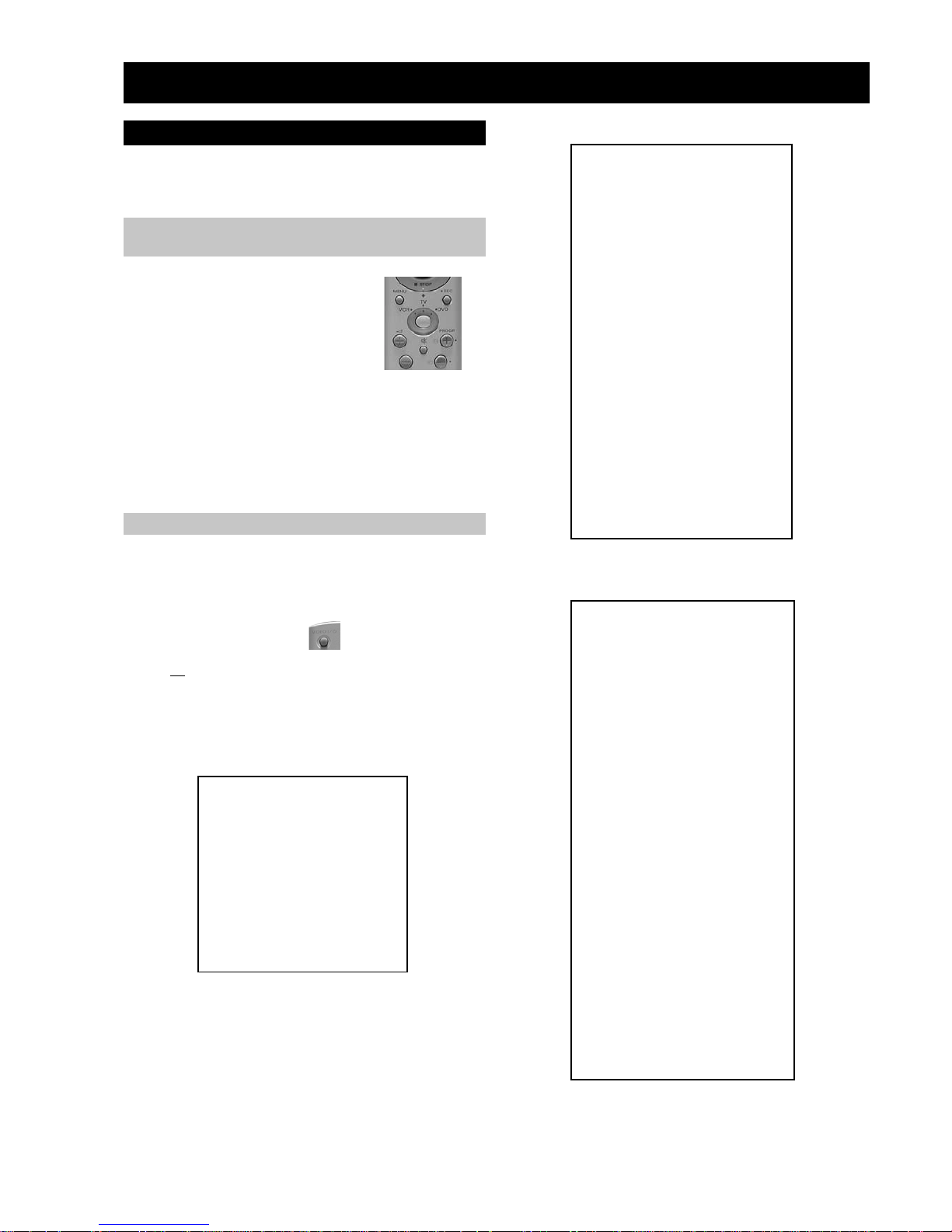
1. Press the VCR/TV/DVD button until the
TV LED lights.
2. Press and hold the yellow button for
approx. 5 seconds until the TV LED
flashes quickly.
- 21 -
Sub Colour Adjustment
1. Receive a PAL colour bar signal.
2. Connect an oscilloscope to Pin 6 of CN7001 [A Board].
3. Program the Remote Commander for operation in Service Mode.
[ See Page 20 ].
4. Adjust the ‘Sub Colour’ [ Using ‘VIDEO’ ‘VIDEO’ ‘12’ ] so
that the Cyan, Magenta and Blue colour bars are of equal levels
as indicated below .
Same Level
B-Out Wavef orm
Sub Brightness Adjustment
1. Input a Monoscope pattern.
2. Program the Remote Commander for operation in Service Mode.
[ See Page 20 ].
3. Press ‘VIDEO’ ‘VIDEO’ 13 on the Remote Commander.
4. Adjust the ‘Sub-Brightness’ data so that there is barely a
difference between the 0 IRE and 10 IRE signal levels.
1. Input a video signal that contains a small 100% white area on a
black background.
2. Connect an digital voltmeter to Pin 10 of J7378 [C Board].
3. Program the Remote Commander for operation in Service Mode.
[ See Page 20 ].
4. Adjust the Sub-Contrast [ Using ‘VIDEO’ ‘VIDEO’ ‘11’ ] to
obtain a voltage of 105 +/- 5V .
Sub Contrast Adjustment
UNEMRORRE
20E
30E
40E
50E
60E
70E
80E
90E
01E
11E
21E
31E
41E
51E
61E
EMITGNIKROW
SRUOH
SETUNIM
PCO
PVO
CNYSV
RKI
CII
MVN
TORPH
RENUT
PDNUOS
ETARNACS
CAD
DNEKCAB
NOCNYD
PIP
)552,0(
)552,0(
)552,0(
)552,0(
)552,0(
)552,0(
)552,0(
)552,0(
)552,0(
)552,0(
)552,0(
)552,0(
)552,0(
)552,0(
)552,0(
0
0
0
0
0
0
0
0
0
0
0
0
0
0
0
41
7
TSUJDAFI
etumotuA
niaGoiduA
gnitaGL
1
0
0
DNUOS
N-M
D-M
S-M
M-S
M-D
M-N
EBB
1B
2B
3B
4B
5B
LWS
FWS
DACMACIN
rorrEMACIN
oeretS
)115,0(
)1-,821-(
)721+,0+(
)721+,0+(
)1-,821-(
)3201,0(
)86+,0+(
)69+,69-(
)69+,69-(
)69+,69-(
)69+,69-(
)69+,69-(
)0+,821-(
)04+,5+(
)7402,0(
)721+,821-(
10001
002
02-
02+
01+
01-
694
82+
0+
0+
0+
0+
0+
0+
03+
0
0+
sutatS0110000000
CAD
GIFNOC
TNOCNIPM
NILH
PARTH
LIOC.TOR
HPSUCOHP
)552,0(
)552,0(
)552,0(
)552,0(
)552,0(
00000000
69
38
721
031
09
ECIVRES
LOCBUS
EUHBUS
PRAHSBUS
THGIRBBUS
TNOCBUS
EVIRD-R
EVIRD-G
EVIRD-B
FFOTUCR
FFOTUCG
FFOTUCB
TXTrB
DSOrB
)36,0(
)36,0(
)36,0(
)36,0(
)51,0(
)36,0(
)36,0(
)36,0(
)36,0(
)36,0(
)36,0(
)51,0(
)51,0(
jdA
13
03
31
21
05
jdA
jdA
82
42
64
7
01
- 22 -
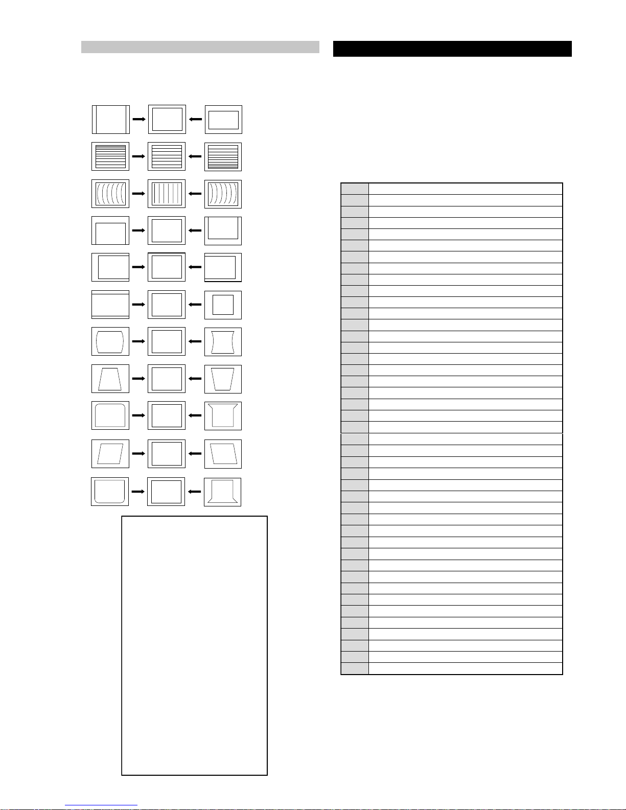
1. Program the Remote Commander for operation in Service Mode.
[ See Page 20 ] and enter into the ‘Geometry’ service menu.
2. Select and adjust each item in order to obtain the optimum image.
Deflection System Adjustment
V SIZE
V LIN
AFC BOW
V POSITION
H POSITION
H SIZE
PIN AMP
TRAPEZIUM
UP CORNER PIN
AFC ANGLE
LO CORNER PIN
YRTEMOEG
HTLBA
EDOMLBA
LBAP
EZISV
NOITISOPV
PMOCV
NILV
NOITCERROCS
EZISH
PMANIP
NIPRENROCPU
NIPM
NIPRENROCOL
MUIZEPART
NOITISOPH
WOBCFA
ELGNACFA
KLBTFEL
KLBTHGIR
TCEPSAV
1MITBKA
2MITBKA
RKI
GNH
GNV
)3,0(
)3,0(
)51,0(
)36,0(
)36,0(
)3,0(
)51,0(
)51,0(
)36,0(
)36,0(
)36,0(
)3,0(
)36,0(
)51,0(
)36,0(
)51,0(
)51,0(
)36,0(
)36,0(
)36,0(
)3,0(
)1,0(
1
0
0
0
0
51
53
33
1
7
7
44
23
92
2
92
2
04
8
9
43
71
74
2
0
Test Mode 2 is a vailable by rogramming the Remote Commander for
operation in Service Mode [ As sho wn on P age 20 ] then pressing the
‘VIDEO’ button twice, OSD ‘TT’ appears. The functions described
below are available by selecting the two numbers. T o release the ‘T est
mode 2’, press 00, 10, 20 ... twice or switch the TV set into Stand-by
mode. In ‘TT Menu’ mode, it is possible to remove the Menu from
the screen by pressing the Speaker Off button once. Pressing the
Speaker OFF button a second time will cause the Menu to reappear .
The function is kept even when the menu is not displayed on
screen !!.
4-3. TEST MODE 2:
72
RKEDAnoitanitseD
82
RKEDAnoitanitseD
13
elbasiD/elbanEffotuhSotuA
63
tsetNO/FFO)MV(noitaludoMyticoleV
14
MVNesilaitini-eR
34
dnuosAlauDtceleS
44
dnuosBlauDtceleS
54
dnuosonoMtceleS
64
dnuosoeretStceleS
84
nigrivnonsaMVNteS
94
nigrivsaMVNteS
35
elbasiD/elbanEnoitaludomrevOMF
55
)SPLA/YNOS(noitcelesrenuT
95
stracS2roPIP+stracS3ledoMtceleS
86
)melborpN(erusaemretnuoc62XelbasiD/elbanE
37
)47.6/5.6(metsys2K/DnotiewZelbanE
47
)47.5/5.6(metsys3K/DnotiewZelbanE
87
thgirllufecnalaB
97
tfelllufecnalaB
78
tsetsyeklacoL
99
unememiTgnikroWdnarorrEyalpsiD
00
ffoedom'TT'
10
mumixamerutciP
20
muminimerutciP
30
%53otemuloVenohpdaeh/rekaepsteS
40
%05otemuloVenohpdaeh/rekaepsteS
50
%56otemuloVenohpdaeh/rekaepsteS
60
%08otemuloVenohpdaeh/rekaepsteS
70
edomgniegA
80
noitidnoCgnippihS
11
tnemtsujdaerutcipbuS
21
tnemtsujdaruolocbuS
31
tnemtsujdassenthgirBbuS
41
tnemtsujdanoitisoPHtxeT
51
tseTlioCnoitatoR
61
%05levelerutciP
91
elbasiD/elbanEedoMyrotcaF
12
RKEDAnoitanitseD
22
LBnoitanitseD
32
RKEDAnoitanitseD
42
UnoitanitseD
52
RKEDAnoitanitseD
62
LBnoitanitseD
 Loading...