

Sony FD Trinitron KV-28DX30U, FD Trinitron KV-32DX30U Service Manual

SERVICE MANUAL
BE-3E
CHASSIS
MODEL
KV-28DX30U
COMMANDER DEST CHASSIS NO.
RM-888 UK SCC-Q25H-A
MODEL
KV-32DX30U
COMMANDER DEST CHASSIS NO.
RM-888 UK SCC-Q25J-A
1

7$%/( 2) &217(176
Section Title Page Section Title Page
Specifications .................... 3
Connectors .................... 4
Self Diagnostic Software .................... 5
1. GENERAL
Overview of the Remote Control................... 9
AutomaticallyT uning the TV .................... 9
Finding your video channel .................... 9
Rearranging the TV Channels .................... 10
Adjusting the Picture .................... 10
Adjusting the Sound .................... 11
Setting up Dolby Pro Logic .................... 11
Changing the Screen Mode .................... 12
ManuallyTuning the TV .................... 12
Vie wing Standard T elete xt .................... 13
Vie wing Digital T elete xt .................... 13
Specifications .................... 14
Troubleshooting .................... 14
2. DISASSEMBLY
2-1. Rear Cover Removal .................... 15
2-2. Chassis Removal .................... 15
2-3. N Board Removal .................... 15
2-4. Service Position .................... 16
2-5. A Board Removal .................... 16
2-6. A Extension Board .................... 16
2-7. Side Control Removal .................... 17
2-8. F4 Bracket Removal .................... 17
2-9. F4 and H8 Board Removal .................... 17
2-10. Picture Tube Remov al .................... 18
Bottom Plates .................... 19
3. SET-UP ADJUSTMENTS
3-1. Beam Landing .................... 20
3-2. Convergence .................... 21
3-3. Focus, Screen [G2] Adjustment.................... 23
3-4. White Balance .................... 23
4. CIRCUIT ADJUSTMENTS
4-1. Electrical Adjustments .................... 24
4-2. TT Test Mode .................... 27
4-3. T Test Mode .................... 28
5. DIAGRAMS
5-1. Block Diagram (1) .................... 29
Block Diagram (2) .................... 33
Block Diagram (3) .................... 37
Block Diagram (4) .................... 41
5-2. Circuit Board Location .................... 44
5-3. Schematic Diagrams and
Printed Wiring Boards .................... 44
* C Board .................... 45
* D Board .................... 49
* D2 Board .................... 52
* VM Board .................... 54
* H Board .................... 56
* A Board .................... 59
* A2 Board .................... 65
* J Board .................... 70
* D1 Board .................... 71
* H7 Board .................... 74
* F4 Board .................... 76
* H8 Board .................... 76
* N Board .................... 77
5-4. Semiconductors .................... 90
5-5. IC Blocks .................... 93
6. EXPLODED VIEWS
6-1. Chassis .................... 95
6-2. Picture Tube .................... 96
7. ELECTRICAL PARTS LIST .................... 97
ATTENTION
CAUTION
SHORT CIRCUIT THE ANODE OF THE PICTURE TUBE AND THE
ANODE CAP TO THE CARBON PAINTED ON THE CRT, AFTER
REMOVAL OF THE ANODE CAP.
WARNING !!
AN ISOLATION TRANSFORMER MUST BE USED DURING ANY
SERVICE WORK TO AVOID POSSIBLE SHOCK HAZARD DUE TO
LIVE CHASSIS, THE CHASSIS OF THIS RECEIVER IS DIRECTLY
CONNECTED TO THE POWER LINE.
SAFETY-RELATED COMPONENT WARNING !!
£
COMPONENTS IDENTIFIED BY SHADING AND MARKED
THE SCHEMATIC DIAGRAMS, EXPLODED VIEWS AND IN THE
PARTS LIST ARE CRITICAL FOR SAFE OPERATION. REPLACE
THESE COMPONENTS WITH SONY PARTS WHOSE PART
NUMBERS APPEAR AS SHOWN IN THIS MANUAL OR IN
SUPPLEMENTS PUBLISHED BY SONY.
ON
APRES AVOIR DECONNECTE LE CAP DE’LANODE,
COURT-CIRCUITER L’ANODE DU TUBE CATHODIQUE ET CELUI
DE L’ANODE DU CAP AU COUCHE DE CARBONE PEINTE SUR
LE TUBE CATHODIQUE.
ATTENTION !!
AFIN D’EVITER TOUT RISQUE D’ELECTROCUTION PROVENANT
D’UN CHÁSSIS SOUS TENTION, UN TRANSFORMATEUR
D’ISOLEMENT DOIT ETRE UTILISÈ LORS DE TOUT DÈPANNAGE
LE CHÁSSIS DE CE RÈCEPTEUR EST DIRECTMENT RACCORDÈ
Á L’ALIMENTATION SECTEUR.
ATTENTION AUX COMPOSANTS RELATIFS Á
LES COMPOSANTS IDENTIFIÈS PAR UNE TRAME ET PAR UNE
£
MARQUE
EXPLOSÈES ET LES LISTES DE PIECES SONT D’UNE IMPORTANCE CRITIQUE POUR LA SÈCURITÈ DU FONCTIONNEMENT,
NE LES REMPLACER QUE PAR DES COMPSANTS SONY DONT LE
NUMÈRO DE PIÈCE EST INDIQUÈ DANS LE PRÈSENT MANUEL
OU DANS DES SUPPLÈMENTS PUBLIÈS PAR SONY.
SUR LES SCHÈMAS DE PRINCIPE, LES VUES
LA SECURITÈ!!
2
LEDOMMETI metsySnoisiveleT metsySoeretS egarevoClennahC metsySroloC
KUI oeretSMACIN96B-12B:FHU
ledoM U03XD82-VK U03XD23-VK
noitpmusnoCrewoPW631W431
MACES,LAP
85.3CSTN,34.4CSTN
)NIOEDIV(
ebuTerutciP
rotcennocoruEnip-12:1
)dradnatsCELENEC(
rotcennocoruEnip-12:2
rotcennocoruEnip-12:3
srotcennoCACR
NIDsrekaepSlanretxE
AICMCPtolSdraC
kcajenohpdaeHkcajinimoerets stnemeriuqerrewoP
stupnioiduAskcajonohp snoisnemiD)d/h/w(mm32x54x012xorppA
stupnioediVskcajonohp thgieW)yrettabgnidulcniton(g59xorppA
tupnioediVSNIDnip4
ediWnortinirTDF
)sehcni82(mc17xorppA
derusaemerutcipmc66xorppA(
)yllanogaid
)sehcni23(mc28xorppA
derusaemerutcipmc67xorppA(
)yllanogaid
noitcelfedeerged011
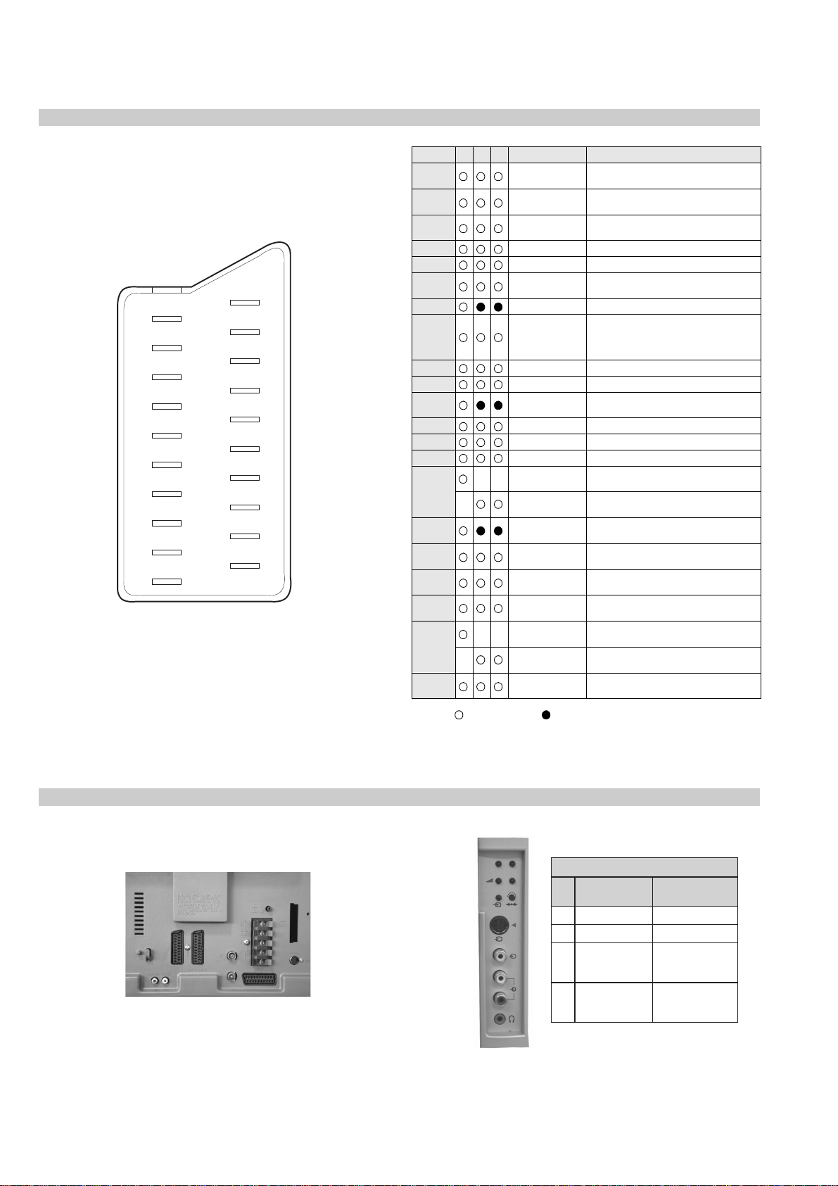
]RAER[slanimreTtuptuO/tupnI
.slangisoediVdnaoiduArofstupnI
.BGRrofstupnI
oiduAdnaoediVVTfostuptuO
.slangis
.slangisoediVdnaoiduArofstupnI
.oediVSrofstupnI
)elbatceles(
.slangisoediVdnaoiduArofstupnI
.oediVSrofstupnI
slangisoiduAdnaoediVrofstuptuO
)tuorotinom(
slangiSoiduAroftuptuoelbairaV
]TNORF[slanimreTtuptuO/tupnI metsyslortnocetomeR
tuptuodnuoSrekaepstfeLdnathgiR
stnemeriuqeRrewoPCAV042-022
snoisnemiD
.slangisoiduAdnaoediVVTfostuptuO
thgieW
seirosseccAdeilppuS
serutaeFrehtO
cdV3
)AAezis(6R
.ecitontuohtiwegnahcottcejbuserasnoitacificepsdnangiseD
)rewoPcisuM(W02x2
)SMR(W01x2
mm225x815x697xorppA"82
mm265x765x388xorppA"23
gk0.44xorppA"82
gk0.26xorppA"23
)1(rednammoCetomeR888-MR
)2(yrettab6RdetangisedCEI
,lortnoCerutciPcimanyD,GPElatigiD
srenuT2,ybloDlautriV
lortnocderarfnI
noitangisedCEIseirettab2
metI
emaNledoM
bmoClaPFFOFFO
PIPFFOFFO
ytiroirPBGRNONO
xoBrefooWFFOFFO
1tracSNONO
2tracSNONO
3tracSNONO
)4(nitnorFNONO
rotcejorPFFOFFO
edom9:61niBKANONO
G/BmroNFFOFFO
ImroNNOFFO
K/DmroNFFOFFO
SUAmroNFFOFFO
LmroNFFOFFO
TASmroNFFOFFO
MmroNFFOFFO
txeteleTNONO
oeretSmaciNNONO
U03XD82-VK U03XD23-VK
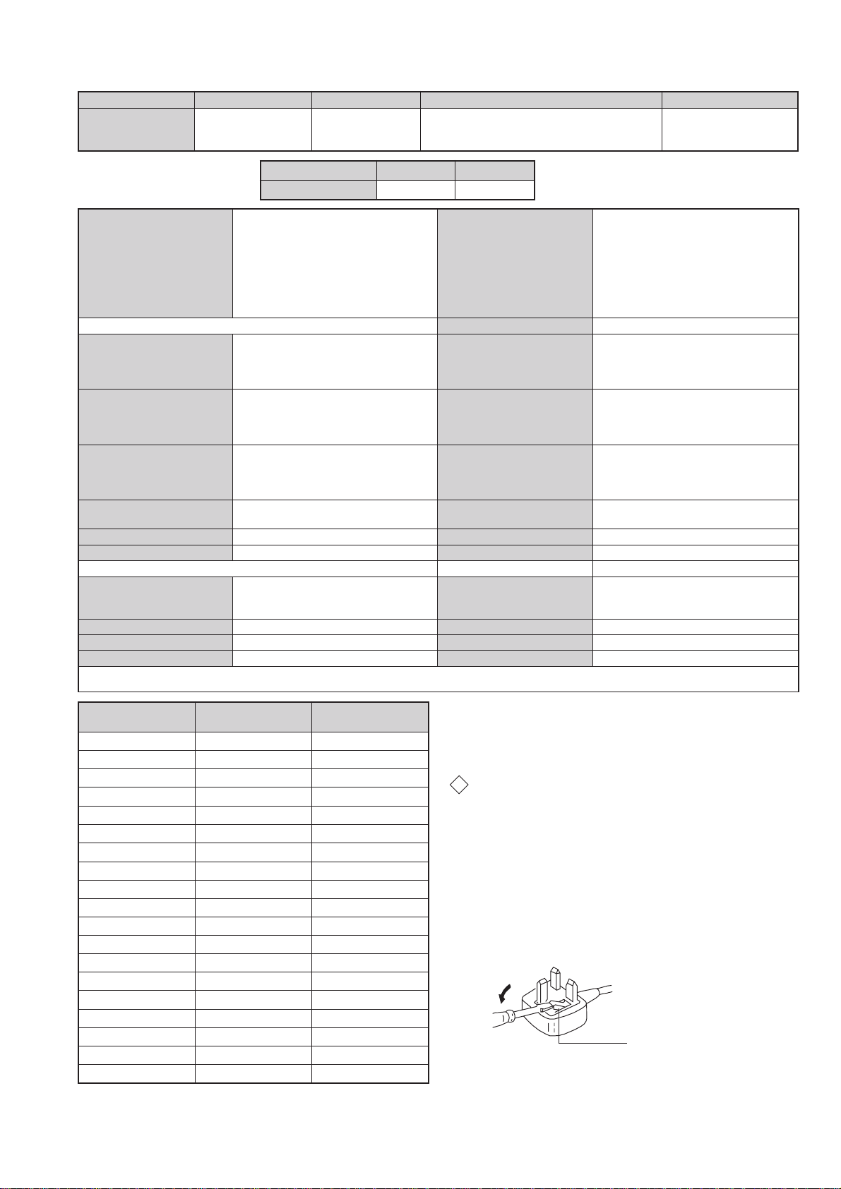
WARNING (UK Models only)
The flexible mains lead is supplied connected to a B.S. 1363 fused plug
having a fuse of 5 AMP rating. Should the fuse need to be replaced, use
a 5 AMP FUSE approved by ASTA to BS 1362, ie one that carries the
ASA
mark.
T
IF THE PLUG SUPPLIED WITH THIS APPLIANCE IS NOT SUITABLE
FOR THE OUTLET SOCKETS IN YOUR HOME, IT SHOULD BE CUT
OFF AND AN APPROPRIATE PLUG FITTED. THE PLUG SEVERED
FROM THE MAINS LEAD MUST BE DESTROYED AS A PLUG WITH
BARED WIRES IS DANGEROUS IF ENGAGED IN A LIVE SOCKET.
When an alternative type of plug is used, it should be fitted with a
5 AMP FUSE, otherwise the circuit should be protected by a 5 AMP
FUSE at the distribution board.
How to replace the fuse.
Open the fuse compartment with
a screwdriver blade and replace
the fuse.
FUSE
3
SLQ FRQQHFWRU
21
19
17
15
13
11
9
7
5
3
1
20
18
16
14
12
10
4
2
Pin No 1 2 3 Signal Signal level
1 Audio output B
2
3
4 Ground (audio)
5 Ground (blue)
6 Audio input A
7 Blue input 0.7 +/- 3dB, 75 ohms positive
8 Function select
9 Ground (green)
10 Open
11 Green Green signal : 0.7 +/- 3dB, 75 ohms,
12 Open
13 Ground (red)
8
6
14 Ground (blanking)
15
_ (S signal Chroma
16 Blanking input
17 Ground (video
18 Ground (video
19 Video output 1V +/- 3dB, 75ohms, positive sync 0.3V
20
_ Video input
21 Common ground
(right)
Audio output B
(right)
Audio output A
(left)
(left)
(AV control)
_ _ Red input 0.7 +/- 3dB, 75 ohms, positive
input)
(Ys signal)
output)
input)
_ _ Video input 1V +/- 3dB, 75ohms, positive sync 0.3V
Y (S signal)
(plug, shield)
Standard level : 0.5V rms
Output impedence : Less than 1kohm*
Standard level : 0.5V rms
Output impedence : More than 10kohm*
Standard level : 0.5V rms
Output impedence : Less than 1kohm*
Standard level : 0.5V rms
Output impedence : More than 10kohm*
High state (9.5-12V) : Part mode
Low state (0-2V) : TV mode
Input impedence : More than 10K ohms
Input capacitance : Less than 2nF
positive
0.3 +/- 3dB, 75 ohms, positive
High state (1-3V) Low state (0-0.4V)
Input impede nce : 75 ohms
(-3+10dB)
(-3+10dB)
1V +/- 3dB, 75ohms, positive sync 0.3V
(-3+10dB)
Connected Not Connected (open) * at 20Hz - 20kHz
5HDU &RQQHFWLRQ 3DQHO )URQW &RQQHFWLRQ 3DQHO
p
- +
niP
oN
S-Video
socket
4
s
4
4
MONO
L/G/S/I
4
R/D/D/D
1dnuorG2dnuorG3tupni)langisS(Y,mho57Bd3-/+V1
4tupni)langisS(CBd3-/+V3.0
4
langiS leveLlangiS
noitarugifnocniptekcosoediVS
V3.0.cnySevitisop
Bd01+3-
evitisop,mho57
.cnyS

BE-3E SELF DIAGNOSTIC SOFTWARE
The errors indicated below can be read using an Error Reader Display (Part Number S-188-900-10) connected to the service connector . Once an
error has been detected it will then be displayed on the two digit error reader. During the power up procedure and during norma l run time, the micro’s
self diagnostic procedures monitor for various errors. Errors displayed refer to the table indicated below .
edoCrorrE egasseMrorrE
00)noitidnoclamronni00swohsredaeRrorrEVT(rorreoN
10 )DELnohsalfesnopserscriShtiwdesufnocebyam(dewollatoN
20)cnyS-VoN&PVO,PCO([pirttiucricnoitcetorP
30)E3-EBrof2rorrenidedulcnI(PVOrofdevreseR
40)E3-EBrof2rorrenidedulcnI(cnyS-VoNrofdevreseR
50BKA
60>ylnOpUrewoP<woLlcSCII
70>ylnOpUrewoP<woLadSCII
80>ylnOpUrewoP<woLlcS&adSCII
90>ylnOpUrewoP<egdelwonkcaonrellortnocelgnuJ
01>ylnOpUrewoP<egdelwonkcaon)0402AXC(hctiwSoediV
11egdelwonkcaonrenuT
21egdelwonkcaonPSM
31egdelwonkcaonMVN
41egdelwonkcaon)9802AXC(hctiwSVA
51desUtoN
61egdelwonkcaon)5781AXC(rednapxEtroP
71desUtoN
81egdelwonkcaon)0708AXC(ecnegrevnoCcimanyD
91 >noitasilaitinIsissahC<-)KOkcehcnorewoplaitiniretfa(elgnujesilaitinitonnaC
02 )tsetv9+(kcehcpurewopretfaeruliafesnopserrellortnoCelgnuJ
12 >noitasilaitinIsissahC<-tesernorewoptonnac)0402AXC(hctiwSoediV
22 )tsetv9+(kcehcpurewopretfaeruliafesnopser)0402AXC(hctiwSoediV
32 )!orcimsaemas-V5+YBTS(noitasilaitiniretfaliafegdelwonkcaMVN
42 >redaeRrorrEnoyalpsiD-lataFeBtoNyaM<eruliafemit-nurPSM
52 >redaeRrorrEnoyalpsiD-lataFeBtoNyaM<eruliafemit-nurPSD
62>eruliaFemiT-nuR<dnesatadretfatuoemitwolkcolCsubL3M
72desUtoN
82>noitasilaitinItA<dnesatadretfatuoemitwolkcolCsubL3M
92desUtoN
03desUtoN
13desUtoN
23desUtoN
33)tsetV5+(dnopsertonseodtxeTtcapmoC
43 >redaeRrorrEnoyalpsiD-lataFeBtoNyaM<eruliafemit-nurtxeTtcapmoC
5
Protection Error
Once every main loop (approximately 200ms OSD mode, 50ms text or menu mode), the micro checks the protection pin (pin 66). If the protection
pin is high 6 successive times, a protection error is diagnosed. The protection pin is not checked during the first 3 - 4 seconds after AC on.
If this error is diagnosed, the r espective NVM r e g ister will be updated and the set goes straight into diagnostic standby with 2 flashes - no reset is
attempted.
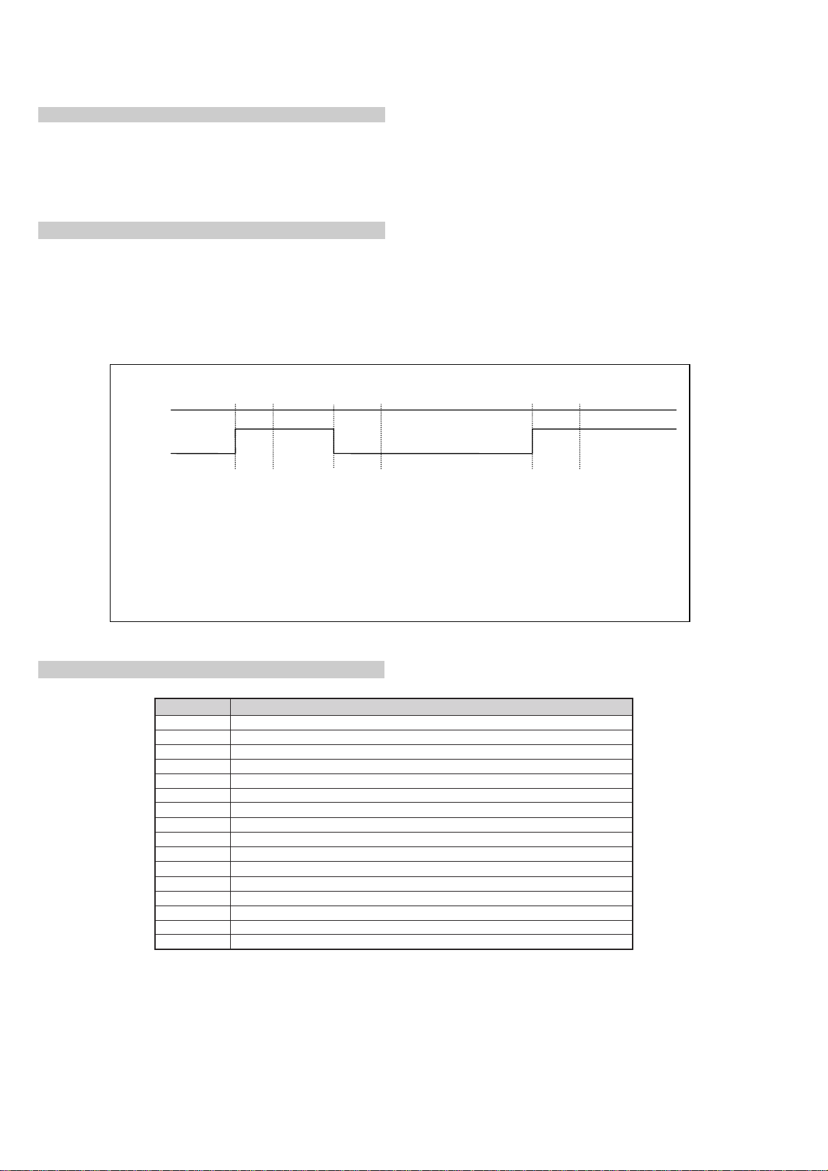
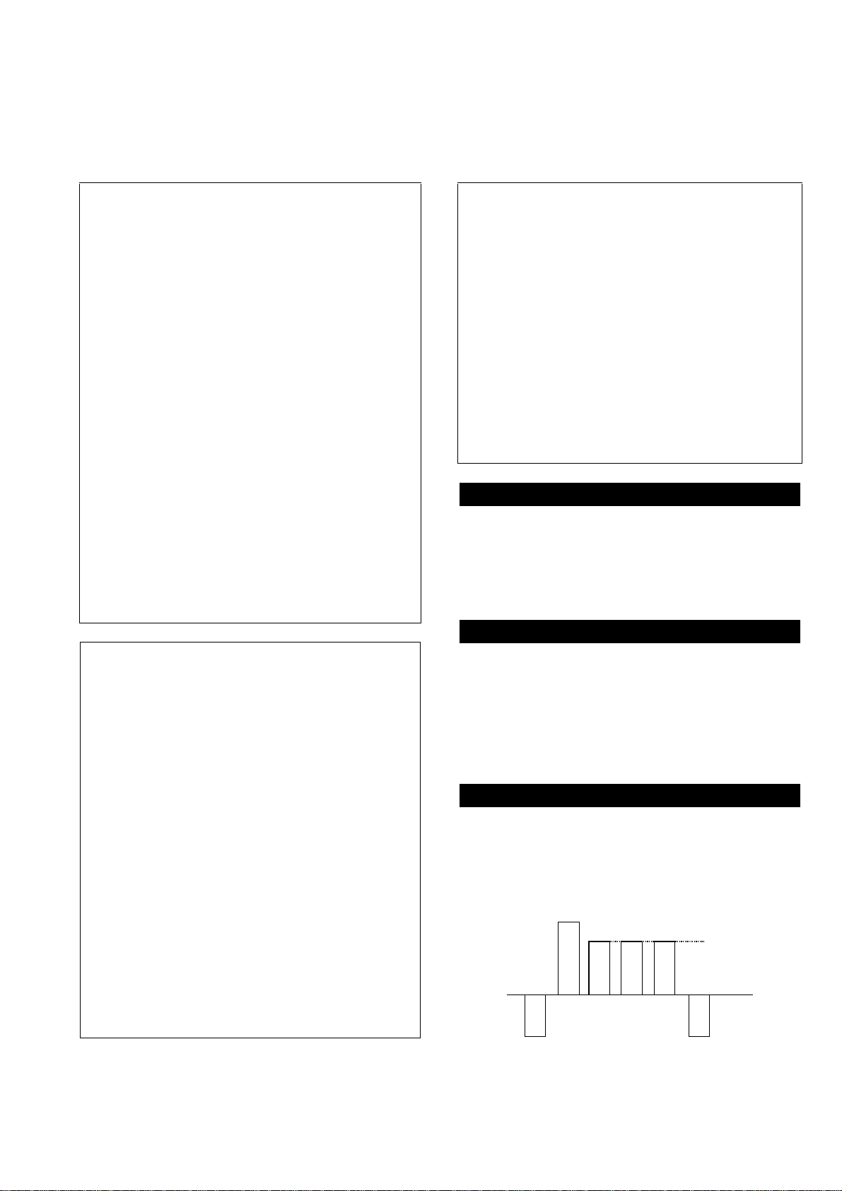
AKB Error (Error 5)
Once every main loop the micro checks the AKB stability by reading the IKR return from the Jungle IC. IKR=1 means that the AKB is stable,
IKR=0 means that the AKB is unstable. If the AKB status is unstable for 10 seconds, an AKB error is diagnosed. AKB stability is not checked
during the first 20 seconds after AC switch on.
If this error is diagnosed, the r espective NVM r e gister will be updated and the r esponse LED will flash 5 times continually, but the set will not go
into standby mode. If the AKB status becomes stable, and remains stable for 10 seconds, the LED will stop flashing.
Time /seconds
0 102030405060708090100
IKR
Return
A B C D E F
A. IKR Return first goes high after 12 seconds
B. Micro begins checking IKR Return status 20 seconds after power on
C. Micro detects IKR return=0
D. Micro detects that IKR has been 0 for 10 seconds; NVM counter is incremented and the LED
starts flashing (flashes 5 times, off for 2 seconds, flashes 5 times, etc.)
E. Micro detects that IKR=1; LED continues to flash
F. Micro detects that IKR has been high for 10 seconds; LED stops flashing.
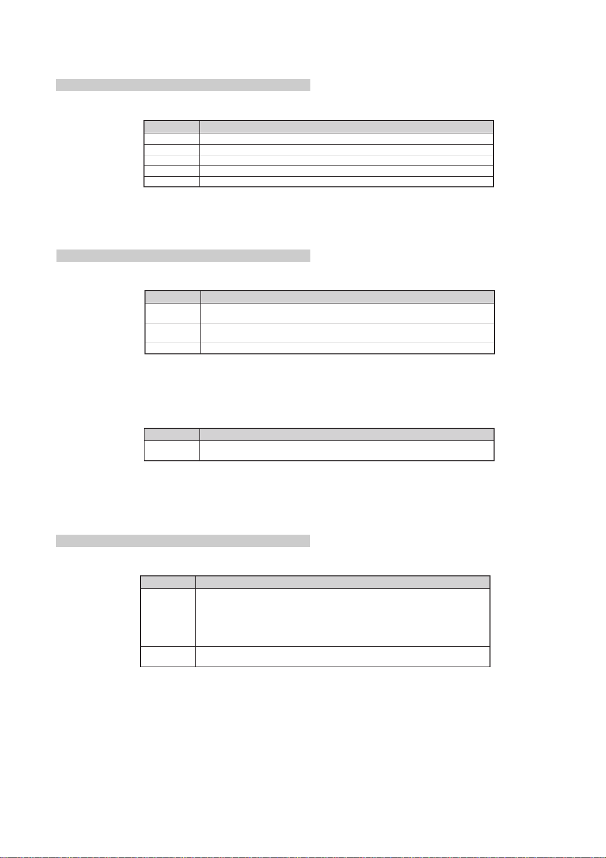
Startup Diagnostic Errors (Error 6-18, 27, 29-32)
MVN egasseMrorrE
6woLnipLCS
7woLnipADS
8woLerasnipADSehtdnaLCShtoB
9)6702AXC(elgnuJehtmorfegdelwonkcaoN
01)0402AXC(hctiwSoediVehtmorfegdelwonkcaoN
11renutehtmorfegdelwonkcaoN
21PSMehtmorfegdelwonkcaoN
31MVNehtmorfegdelwonkcaoN
41hctiwSoediV9802AXCehtmorfegdelwonkcaoN
61rednapxEtroPoediV5781AXCehtmorfegdelwonkcaoN
81)0708AXC(ecnegrevnoCcimanyDehtmorfegdelwonkcaoN
72tsetMARtxeTtcapmoCretfawolnipDXT_L3M
92wolnipDXT_L3M
03wolnipDXR_L3M
13wolnipNEL3M
23liaftsetMARtxeTtcapmoC
If any of these errors ar e detected, the r espective NVM r e gister will be incr emented. The softwar e will then carry on with the power up sequence.
6
General IIC Device Run-time Errors (Errors 19-23)
MVN egasseMrorrE
91esilaitiniotgnitpmettanehwelgnuJmorfegdelwonkcaoN
02sretsigerdaerotgnitpmettanehwelgnuJmorfegdelwonkcaoN
12noitasilaitinignirudteseretelpmoctonnachctiwSVA
22 sretsigerdaerotgnitpmettanehwhctiwSVAmorfegdelwonkcaoN
32etirwrodaerotgnitpmettanehwMVNmorfegdelwonkcaoN
If any of these errors ar e detected, the r espective NVM r e gister will be incr emented and the software will carry on.
Compact Text Run-time Errors (Errors 26, 28, 33 & 34)
MVN egasseMrorrE
62
82
33secivedfonoitasilaitinigniruddeliaftsetMARtxeTtcapmoC
)elbissop
)elbissopsaw
sawnoitacinummocontahtseilpmi(18retsigergnikcehcnehwwolnipDXT_L3M
noitacinummocontahtseilpmi(esilaitiniotgnitpmettanehwwolnipDXT_L3M
In the case of these errors, the ‘device reset’ pin will be held low for 60ms, causing a hardwar e reset of Compact Text. Following this r eset, a long er
timeout will be allowed for the M3L bus to recover. If the error still exists, the NVM r e gister will be incremented and the software will carry on.
MVN egasseMrorrE
43
)detpurrocemocebroteserrehtie
sahtxeTtcapmoCtahtseilpmi(hgihnipDXT_L3Mtub,liafkcehc18retsigeR
In the case, the ‘device reset’ pin will be held low for 60ms, causing a har dwar e r eset of Compact Text. Compact Text will then be re-initialised and
the NVM counter updated. This is the same as for errors 26, 28 and 33 e xcept tha t the M3L b us timeout is not changed.
MSP and DSP Run-time Errors (Errors 24 & 25)
MVN egasseMrorrE
:gniwollofehtfoynaybdesuacebnac42rorrE
42
.)detpurrocemoceb
52
.)detpurroc
.)detpurrocemocebroteserrehtiesahPSM
.noitcurtsniteseregdelwonkcaotsliafPSM-
ehttahtseilpmi(liafkcehcretsigeRelacserPtracS,noitasilaitiniPSMretfA-
roteserrehtiesahPSMehttahtseilpmi(liafkcehcretsigeRelacserPtracS-
emocebroteserrehtiesahPSMehttahtseilpmidetpurrocetybtsetPSD
For both these errors, the softwar e will refresh the MSP and DSP registers. If the errors still e xist, the NVM counter will be incremented, and the
software will carry on.
7

Error Display Mode
Error Display Mode is entered by the following sequence of commands :
Standby -> Information -> Digit 5 -> Volume Down -> TV
This mode will display a special menu, which will list all possible errors and the number of occurrances of each error (0 - 255, as stored in the
NVM). There will also be a display of the current error (00 if no error). This display mode will appear as follows :
ERROR DISPLAY MODE
Current Error Code = 00
Error Code Occurrences Error Code Occurrences
22190
3--200
4--210
50220
60230
70240
80254
90265
10 0 27 89
11 0 28 3
12 0 29 0
13 0 30 0
14 0 31 0
15 3 32 0
16 0 33 3
17 0 34 38
18 6
Whilst in this mode, the number of occurences of each error can be reset to 0 by following sequence of Sircs commands: Digit 8 -> Digit 0.
‘TT08’ will also reset this NVM data.
This mode can only be exited by switching off the TV.
The Current Error Code can also be read by using a TV Error Reader (IIC slave address 42H). This device simply receives 1 data byte, which is the
error number in binary coded decimal form.
8
SECTION 1 GENERAL
7
BBC TWO
Yes
No
Confirm: OK
Do you want to start
automatic tuning?
buttons on
v
or
V
buttons to select
v
or
V
Confirm: OK
Please confirm that
antenna is connected
v
v
or
or
V
V
The operating instructions mentioned here are partial abstracts from the ‘Operating
Instruction Manual’. The page numbers of the ‘Operating Instruction Manual’ remain
as in the manual.
The digital channels will be stored on programme
to read the TV menu screens. Press the
press the OK button to confirm your selection.
screen enabling you to select in which language you wish
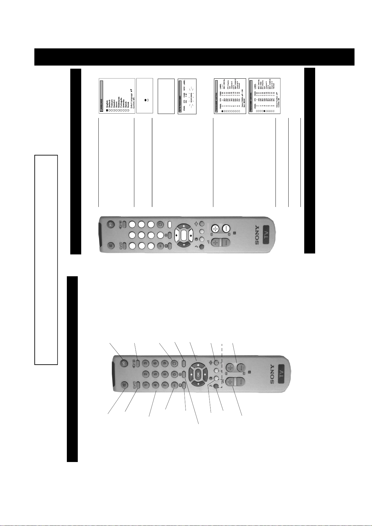
1. When switching on the TV for the first time, the
‘LANGUAGE’ menu appears automatically on the TV
the remote control to select your chosen language then
your selected language. Press the
2. The ‘automatic tuning’ menu appears on the TV screen in
‘YES’ then press the OK button to confirm.
3. Ensure the antenna is connected as instructed, then press
9
2 345 6
8
1
6. Automatically tuning the TV
Getting Started
When you first switch on the TV, the following sequence o f menu screens ap pear on the TV en abling you to 1) ch oose a language
for the TV menu screens, 2) tune channels to the TV, 3) arrange the channels.
7
numbers 1-90 and the analogue channels on programme
the OK button to confirm. The TV starts to automatically
patient and do not press any buttons.
numbers 91-99.
search and store all available channels for you. Please be
MENU
0
Note: If any digital channels are stored on programme
OK
analogue channels.
on the TV screen enabling you to change the order of the
channels on your TV. If you do not wish to use this
option, proceed to step 5.
numbers 91-99 during the Automatic Tuning procedure,
TV’ on page 19 of this manual to tune in and store the
then no analogue channels will be allocated. If this
happens, please refer to the section ‘Manually tuning the
channels, the ‘PROGRAMME SORTING’ menu appears
If you wish to change the channel order, pr ess the
want to move, then press the OK button. Press the
buttons on your remote control to select the channel you
4. When the TV has finished tuning in all available
PROGR
RM-888
sort the order of other channels on your TV.
programme position. Repeat this procedure if you wish to
confirm. The selected channel now moves to its new
your selected channel then press the OK button to
buttons to select the new programme number position for
screen.
remote control to view the TV channels.
5. Press the MENU button to remove the me nu from the TV
6. Press the PROGR+/- or the numbered buttons on the
7. Finding your video channel after tuning
If you have connected a VCR to your TV, you now need to find the video channel.
instruction manual.
Note: If you wish to move your video channel to a different programme position, re fer to the ‘Re-arra nging the TV ch annels’ section in this
1. Press the PROGR +/- buttons on the remote control until the video picture appears on the TV screen.
9
To temporarily switch off TV
Press to temporarily switch off TV. Press again to
switch on from standby mode. To save energy, we
recommend switching off completely w he n the TV is
automatically into standby mode.
To select input signal or freeze teletext
without any button being pressed, the TV switche s
NOTE: After 15-30 minutes without a TV signal and
not in use.
cancel.
Optional Equipment section). In teletext mode, press
To return to previous channel
Press to select inputs from the TV sockets (see Using
Press to return to the previous channel you were
to freeze the displayed page. Press once agai n to
watching. Note: This can be done only if you watched
Press to use the TV menu system. Press again to
To display the menu
the previous channel for at least 5 seconds.
remove the menu from the TV screen.
MENU
To select menu items
options available when in the menu system of this TV.
display the channel listing table.
To change screen format
Use these buttons and the OK button to select the
Press to change the size of the screen.
Pressing the OK button in normal TV mode will
See Teletext section of manual for details.
To select channels
Press to select channels.
PROGR
RM-888
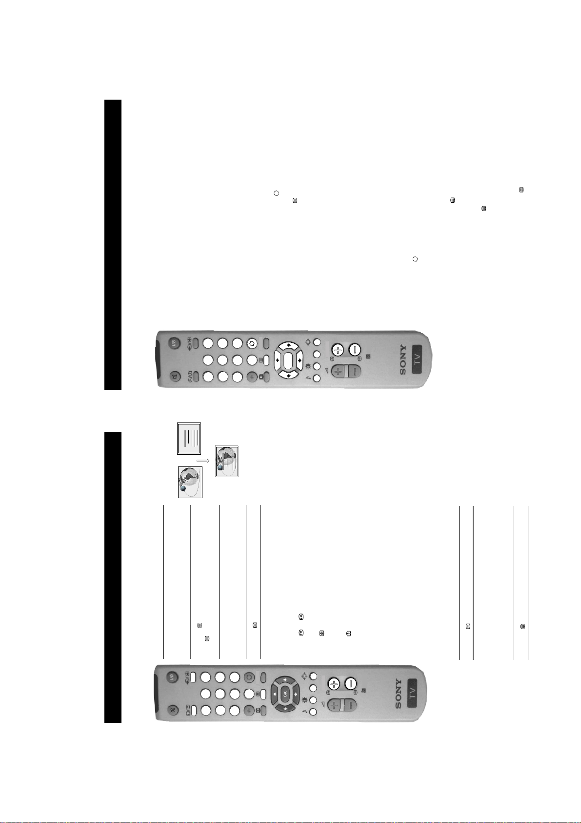
Overview
Overview of the remote control buttons
To mute sound
Press to mute TV sound. Press again to
Guide. Press again to remove display.
Press to switch on Teletext.
Press to display the Electronic Programme
To select Teletext
To display picture menu
Press to change the picture settings. Press
number of your choice.
To select EPG
answers to a quiz) then press again to
cancel.
restore the sound.
To reveal on screen information
Press to reveal all on-screen indications.
Press again to cancel. In teletext mode,
Press the numbered buttons to select
To select channels
press to reveal concealed information (e.g.
-/-- button again to enter the programme
e.g.23, press -/-- first, then the buttons 2 and
3. If you enter an incorrect first digit, select
channels.
For double digit programme numbers,
To display sound menu
the OK button to remove the displa y.
Press to change the sound settings. Pr ess the
To adjust TV volume
OK button to remove the display.
Press to adjust the volume of the TV.
9
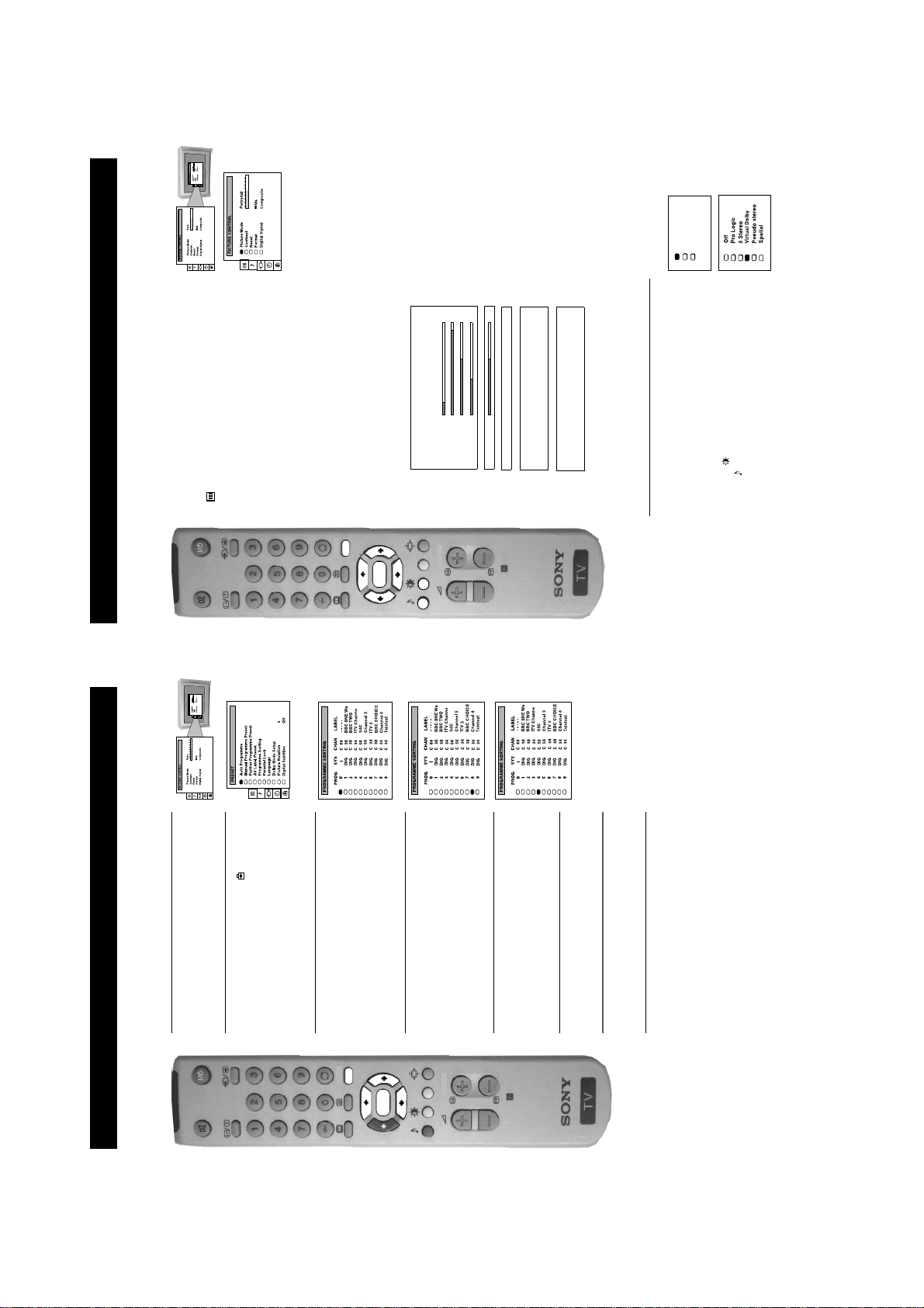
Personal
Movie
Live
b button to
b button to confirm. For a
Movie (for films)
b button to confirm.
V or v buttons on the remote control to select the
V or v buttons to select the item on the screen you
symbol on the menu screen then press the
enter the ‘PICTURE CONTROL’ menu.
menu on the TV screen.
1. Press the MENU button on the remote control to display the
2. Press the
Adjusting the picture
Additional TV Features
Although the picture is adjusted at the factory, you can modify it to suit your own taste.
wish to adjust then press the
description of the menu items and their effects, see the table
below.
3. Press the
b or B buttons to adjust your selected item.
store the new setting.
adjust then press the
V or v buttons to select the item on the screen you wish to
4. If you selected ‘Picture Mode’ or ‘Format’ in step 3, press the
B button to return to the ‘PICTURE CONTROL’ menu.
6. As soon as you have adjusted the item, press the OK button to
5. Press the
MENU
9. Press the MENU button to remove the menu from the TV
7. If you selected ‘Picture Mode’ or ‘Format’ in step 3, press the
8. Repeat steps 3-7 to adjust the other items.
OK
B Live (for live broadcast s)
Brightness*
Colour*
Sharpness*
Hue**
screen.
Picture Mode Picture Modeb Personal (for individual settings)
PROGR
Scroll
Auto 16:9 b Off B On
that gives you the picture quality you prefer
Format Format (refer to page 14 for details)
Contrast
Reset Resets picture to factory preset levels
RM-888
Digital Signal Set to Composite or RGB. Choose the option
*Only if you select ‘Personal’ in ‘Picture Mode’.
** Available for NTSC colour system only.
Changing picture and sound modes quickly
without entering the ‘PICTURE CONTROL’ or the ‘SOUND
You can quickly change the Picture Mode or the Sound Mode
V or v buttons to select the desired mode.
or the symbol for sound modes.
CONTROL’ menu screens.
screen.
3. Press the OK button to remove the display from the TV
1. Press the symbol on the remote control for picture modes
2. Press the
10
Additional TV Features
Re-arranging the TV channels
After tuning the TV, you can use this feature to change the channel order.
b button to enter the
b button to enter the ‘PROGRAMME
menu screen then press the
the menu on the TV screen.
1. Press the MENU button on the remote control to display
‘PRESET’ menu.
2. Press the V or v buttons to select the symbol on the
SORTING’ menu.
press the
3. Press the v button to select ‘Programme Sorting’ then
MENU
to move then press the OK button to confirm.
4. Press the V or v buttons to select the channel you want
OK
PROGR
5. Press the V or v buttons to select the new programme
RM-888
position (e.g. PROG 4) for your selected channel, then
press the OK button to confirm. The selected channel
now moves to its new programme position.
6. Repeat steps 4 and 5 if you wish to sort other chan nels.
screen.
7. Press the MENU button to remove the menu fr om the TV
24
10
13
Additional TV Features
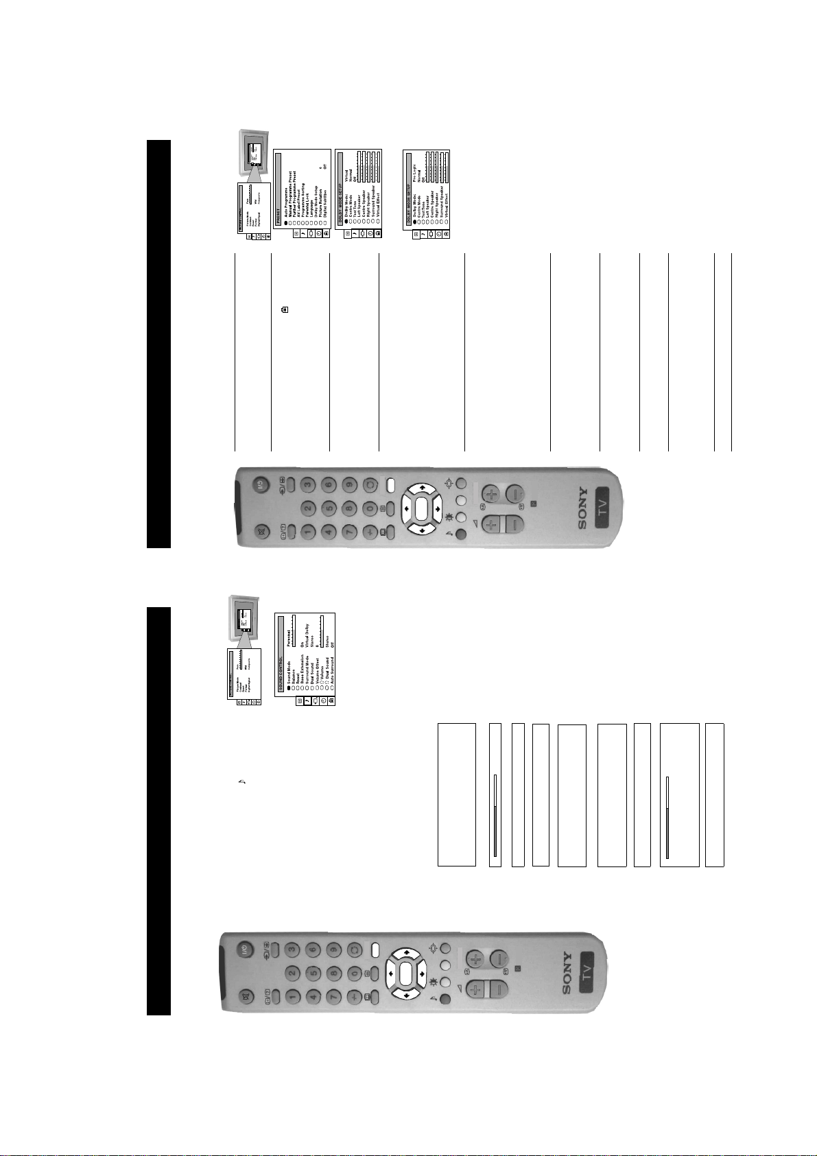
Setting up Dolby Pro Logic
Before listening to Dolby Pro Logic encoded programmes, you can adapt the Dolby features to suit your own taste. This is only
b button to enter the
b or B buttons to select ‘On’,
b button to enter. Press the b or B buttons to
b button to confirm. The tone remains at the left
b button to enter the
‘PRESET’ menu.
menu screen then press the
the menu on the TV screen.
1. Press the MENU button on the remote control to display
2. Press the V or v buttons to select the symbol on the
Logic mode.
Note: There will be no output available from the headphones or the audio ou tput sockets o n the rear of the TV d uring Dolby Pro
required if you have connected your own external speakers (SS-CR190 or equivalent), and/or if you decide to chan ge the speaker
positions.
‘DOLBY MODE SETUP’ menu.
the menu screen then press the
3. Press the V or v buttons to select ‘Dolby Mode Setup’ on
MENU
select one of the following modes then press the OK
press the
button to store the chosen mode:
Pro Logic: all 5 speakers are activated
3 stereo: surround speakers are not used
4. Press the V or v buttons to select ‘Dolby Mode’, then
OK
Virtual: no external speakers required. Do not select this
mode if you wish to receive Dolby Pro logic
5. Press the v button to select ‘Centre Mode’, then push the
PROGR
b button to enter. Press the b or B buttons to select one
of the following modes then press the OK button to store
Wide: wider bandwidth for centre speaker
the chosen mode:
Normal: all 5 speakers are activated
Phantom: centre speaker is not used (This cannot be
then press the OK button.
button to enter. Press the
The test tone will cycle through all the speakers.
speaker.
selected if you have chosen “3 stereo” mode in step 4)
6. Press the v button to select ‘Test Tone’ then push the b
the
7. Press the v button to select the ‘Left Speaker’, then press
press the OK button.
8. Press the V or v buttons to alter the sound level, then
‘Right’, and ‘Surround’ speakers, so that the sound output
9. Repeat steps 7 and 8 to select and adjust the ‘Centre’,
from all speakers are balanced in relation to your sitting
position.
on page 11 and set the Surrou nd Mode to Pro Logic.
10.Press the MENU button to remove the display.
Note: After setting up Dolby ProLogic, refer to the ‘Adjusting the sound’ section
RM-888
11
b button to confirm. For a
b button to enter the ‘SOUND
V or v buttons to select the symbol on the
V or v buttons to select the item on the screen you
CONTROL’ menu.
menu screen then press the
menu on the TV screen.
1. Press the MENU button on the remote control to display the
2. Press the
Adjusting the sound
Additional TV Features
Although the sound is adjusted at the factory, you can modify it to suit your own taste.
wish to adjust then press the
3. Press the
b button to confirm.
Jazz
Rock
In ‘Personal’ mode, Treble and Bass can be adjusted
Only available when ‘Surround Mode’ is set to ‘O ff’
b or B buttons to adjust your selected item.
5. Press the
6. As soon as you have adjusted the item, press the OK button
to store the new setting.
MENU
7. If you selected ‘Sound Mode’ or ‘Surround Mode’in step 3,
B button to return to the ‘SOUND CONTROL’
press the
menu.
screen.
9. Press the MENU button to remove the menu from the TV
8. Repeat steps 3-7 to adjust the other items.
OK
V or v buttons to select the item on the screen you
wish to adjust then press the
description of the menu items and their effects, s ee the tab le
below.
press the
4. If you selected ‘Sound Mode’ or ‘Surround Mode’ in step 3,
B Pop
Sound Mode b Personal
PROGR
Balance
Reset Resets sound to factory preset levels
RM-888
Off --> Pro Logic --> 3 Stereo --> Virtual Dolby -->
Bass Extension Boosts bass by a fixed am ount
Surround Mode Choose from the special sound effects:
(for a bilingual broadcast)
adjusted over a range of -12 to +12.
A for channel 1B b B for channel 2
Pseudo Stereo --> Spatial
Volume Offset B The channel volume level can be b
Dual Sound StereoBbMono (for a stereo broadcast)
(for a bilingual broadcast)
A for channel 1 B b B for channel 2
Surround sound when transmitted.
Headphones
Auto Surround Set to ‘On’ to automatically select Pro Logic
i Volume
i Dual Sound Stereo BbMono (for a stereo broadcast)
11
rmat
19
03
Additional TV Features
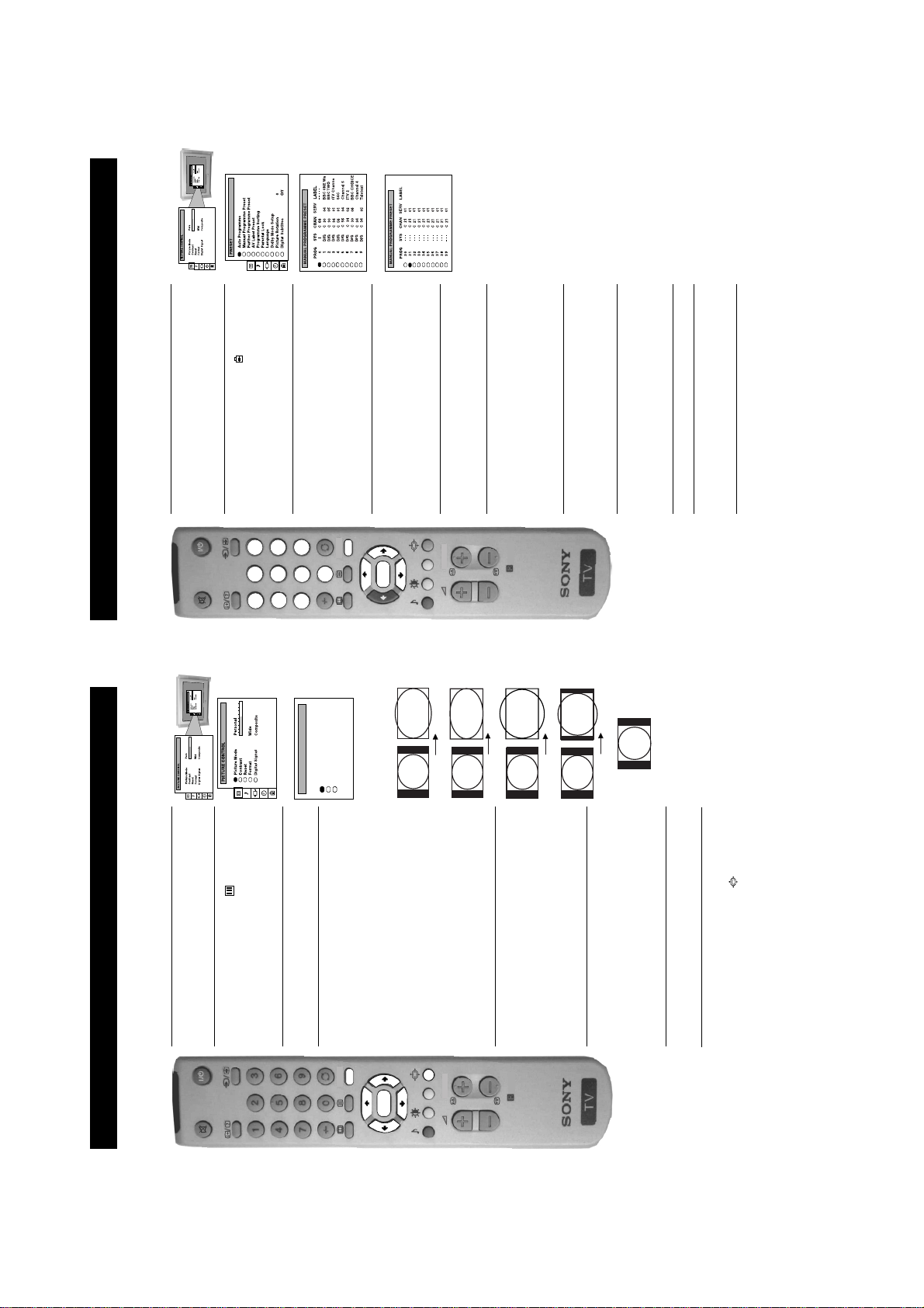
Manually tuning the TV
You have already tuned the TV automatically using the instructions at the start of this manual. You can however carry out this
operation manually, adding channels to the TV, one at a time.
1. Press the MENU button on the remote control to display
b button to enter
b button to enter.
b button to confirm.
V or v buttons on the
b button to enter the PRESET menu.
V or v buttons to search for the next available
digital programmes only), select each digit in turn and press
the menu on the TV screen.
screen then press the
2. Press the V or v buttons to select the symbol on the TV
2 345 6
1
3. Press the V or v buttons to select ‘Manual Programme
9
8
7
FORMAT
Preset’ on the menu screen then press the
0
Wide 0On
Format
Scroll
the ‘MANUAL PROGRAMME PRESET’ menu.
MENU
Auto 16:9
4. Press the V or v buttons to select an unused programme
OK
PROGR
Smart
(I for analogue or DIG for digital) or a video input source
5. Press the V or v buttons to select the TV broadcast system
(AV1, AV2 ...) then press the
6. Select the first number digit of ‘CHAN’ (channel) then the
RM-888
Wide
number for your channel then press the
channel.
second number digit of ‘CHAN’ with the numbered buttons
on the remote control
or
Press the
Zoom
the numbered buttons on the remote control to change to
7. If you wish to change the ‘SERV’ service number (on
14:9
remote control to continue searching for the desired
number you selected, press the
your desired service.
channel.
8. If you do not wish to store this channel on the programme
4:3
press the MENU button to remove the menu from the TV
screen.
9. If this is the channel you wish to store, press the OK button.
10.Repeat steps 4-9 if you wish to store more channels then
NOTE: After manually tuning in the channels you require, you
can sort the channels into the order you prefer by following the
procedure ‘Re-arranging the TV channels’ on page 24.
b button to
B or b buttons to
b button to enter the ‘PICTURE
screen then press the
menu on the TV screen.
1. Press the MENU button on the remote control to display the
Changing the screen mode
Additional TV Features
Using this Screen Mode feature you can change the aspect ratio of the screen.
CONTROL’ menu.
2. Press the V or v buttons to select the symbol on the menu
b button to enter the ‘FORMAT’ menu.
V or v buttons to select ‘Format’ then press the b
Press the
one of the following modes then press the OK button to store
button to enter. Press the
the chosen mode:
screen then press the
3. Press the V or v buttons to select ‘Format’ on the menu
4. Format
MENU
broadcasts
• Smart - imitation of wide screen effect (16:9) for 4:3
OK
conventional 14:9 picture
broadcast in cinemascopic format
• Wide - for 16:9 broadcasts
• Zoom - imitation of wide screen effect (16:9) for movies
• 14:9 - compromise between 4:3 and 16:9 format - for
PROGR
V or v buttons to select ‘Scroll’. You can use
highlight the present value then press the
‘Scroll’ to move the screen up or downwards in order to see
Press the
5. Scroll (Applies to Zoom, 14:9 or Sm art format only)
• 4:3 - conventional 4:3 picture
RM-888
adjust the screen position over a range of -5 to +5. Press the
the cut-off parts (e.g. to read subtitles). Press the
b or B buttons repeatedly to select
OK button to store.
B or b buttons to select ‘On’ if you
V or v buttons to select ‘ Auto 16:9’ then p ress the b
Press the
button to enter. Press the
wish the TV to switch automatically to wide format when a
6. Auto 16:9
16:9 broadcast is detected, or ‘Off’ to retain the format
screen.
selected in step 4. Press the OK button to store.
7. Press the MENU button to remove the menu from the TV
Note: You can change the picture format quickly without having
to enter the menu system. Simply press the button repeatedly
until the picture is displayed in the format you desire.
14
12
V,
V, v,
V, v, B or b buttons to select the symbol then press
the OK button to display the chosen information.
coloured buttons on your remo te control to display the various
the OK button to look for that channel in the channel table.
numbered buttons on your remote control to sel ect th e relev an t
Selecting the dedicated digital
Viewing Digital Teletext
Teletext
Most of the digital TV channels broadcast information via teletext. This digital service includes high quality text and graphics as
well as advanced navigational options. Additionally, this television set has access to a dedicated digital teletext channel.
channel number. If you do no t kn ow the c han nel nu mbe r, p ress
1. To view the dedicated digital teletext service, press the
teletext channel
25
153
v, B or b buttons to guide the on-screen cursor to the required
on-screen to display the teletext information, then press the
area of the screen, then press the OK button to display the
chosen information.
on the remote control to directly enter the page number required
and to display the various pages of text information.
‘OK’ or ‘Cancel’, press the OK button for ‘OK’ or the
button for ‘Cancel’.
or the PROG +/- buttons, and then select an alternative digital
2. Once the teletext channel is displayed, follow the instructions
2 345 6
1
101
98
3. Alternatively, you can use the numbered and coloured buttons
4. If when viewing the teletext pages, you are requested to select
9
MENU
0
8
7
channel.
5. When you have finished viewing teletext, press the button
OK
channels. Sometimes this is indicated by a small symbol or text
PROGR
digital channels
Normal teletext services may also be available on other digital
display on your TV screen, superimposed on the channel you are
watching.
1. Press the
RM-888
Selecting teletext from the other
pages of text information. If when viewing the teletext pages,
you are requested to select ‘OK’ or ‘Cancel’, press the OK
button for ‘OK’ or the button for ‘Cancel’.
B or b buttons, the coloured buttons and/or the numbered
buttons to access the chosen information.
2. Alternatively, you may be requested to use the numbered and
3. Once the text information is displayed on screen, use the
and then select an alternative digital channel.
4. When you have finished viewing teletext, press the button
available.
information available and/or the coloured buttons for the
your remote control to display any text service which may be
functions shown on screen.
button to return to normal TV.
On other channels there may be no on-screen symbol, but you can
2. Press the numbered buttons to select the various pages of
see if there is a digital service as follows:
1. When watching a digital TV channel, press the button on
3. When you have fini shed using the text service, press the
26
25
TELETEXT
Index
Programme
News
Sport
Weather
25
153
101
98
TELETEXT
Index
Programme
News
Sport
Weather
the remote control to select the channel which carries the
teletext service you wish to receive.
Selecting Teletext
1. When viewing analogue channels press a numbered button on
2. Press the on the remote control to switch on teletext. Press
Viewing standard teletext
Teletext
Teletext is an information service transmitted by most TV stations.
the TV screen.
the button again if you wish to superimpose teletext on to
2 345 6
1
3. Select your required page using the numbered buttons on the
remote control. If you make an error, complete the number , then
9
8
7
re-enter the correct page number.
4. Press the button to switch off teletext.
Using Other Standard Teletext Functions
To move to the next or preceding page
To freeze a Teletext page
Press the or buttons to select the previous or next page.
Press the button to freeze the page. Press again to cancel the
freeze.
Revealing concealed information (eg:answers to a quiz).
MENU
0
PROGR
When the colour coded menu appears at the bottom of a page, press
Press the button to reveal information. Press again to conceal the
information.
the colour buttons (red, green, yellow or blue) on the remote control
Using colour buttons to access pages (Fastext)
to access the corresponding page.
Displaying TOP-Text (when available)
With TOP-Text you can access pages easily by selecting blocks or
groups of pages. The block is a category (for example Sports) which
includes the groups (for example Football). When TOP-Text is
broadcast, a colour coded menu appears at the bottom of the screen.
The colours of this menu correspond to the red, green, yellow and
blue buttons on the remote control. Press these coloured buttons to
displayed the desired page s.
RM-888
1. Press the butto n to display teletext.
Red: to go back to the previous page.
Green: to proceed to the next page.
Yellow: to proceed to the first page of the next group.
Blue: to proceed to the first page of the next block.
2. Press the coloured buttons to search for the page you desire:
3. Press the button twice to return to normal TV.
13
/
your aerial at.
•Power off.
• TV in standby.
• Aerial disconnected.
• Picture preset level adjustment.
• No digital transmissions in your area.
• No digital transmissions from the transmitter you are currently using.
• Weak signal.
• Unsuitable aerial.
• Fault (irregular flash).
• Digital mode Timer Record active (regular flash).
• Volume control.
• Programme not being transmitted.
• Programme used only for data (no picture or sound).
• Scrambled/subscription-only channel.
• The button marked on the rear of the TV is pressed in.
• The TV has been set up to receive Dolby Pro Logic.
• Colour level setting.
• Wrong external mo de selected on an RGB video source.
• Batteries low.
• Inputs from external equipment not switched off.
remote control.
• Press the button on the front of the TV.
• Plu g in the TV.
• If the indicator is on press the button or a numbered button on the
• Tune in the analogue channels available using th e ‘Manually tuning the TV’
• Select on the TV menu system then adjust the brightness, picture and colour
• Check the aerial connection.
instruction in this manual, then contact a local installer to find out when digital
balance levels.
a local installer)
transmissions begin in your area.
• Contact a local installer to find out which transmitter you should be pointing
• Upgrade to a hi gher gain aerial.
• Ensure aerial is correctly aligned to transmitter.
• Ensur e aerial is plugged direct ly into the TV (not through other equipment).
• See ‘Re-arranging the TV chann els’ section.
• Do not open the cabinet, refer to qualified personnel.
• Change your aerial to cover the channels used by digital pro gra m mes. (Co n tact
• Contact your nearest Sony Service Centre.
• Subscribe to pay-per-view broadcaster.
• See ‘Ski pping programme positions’ section.
screen.
• Press the + button on the remote control.
• If is displayed on the screen, press the butto n on the remote control.
• Press the button repeatedly until the RGB symbol is displayed on
• Select on the TV menu system then adjust the colour setting.
Troubleshooting
Additional Information
Problem Cause
No picture, no sound.
Poor or no picture (screen is dark), but good sound.
No picture on any channel after digital tuning.
Here are some simple solutions to problems which may affect the picture and sound.
Some channels are blank.
Good Picture, no sound.
Standby indicator flashing.
No head phone output and no ou tput from th e a udio
sockets marked on the rear of the TV.
Poor picture quality.
No colour on colour programmes.
Remote control does not func tio n .
Distorted picture when changing programmes or
selecting Teletext.
Cause • Solution
TV in standby.
Aerial disconnected.
Power off.
Picture level adjustment.
are currently using.
Unsuitable aerial.
Weak signal.
No digital transmissions in yo ur area.
No digital transmissions from the transmitter you
Scrambled/subscription-only channel.
Programme information without picture or sound.
Fault.
Volume control.
Wrong external mode selected.
you can contact the Sony UK Digital HelpLine on 0870 600 1717.
Colour level setting.
• If you continue to have these problems, have your TV serviced by qualified personnel or
• NEVER open the casing yourself.
34
33
Additional Information
Specifications
21-pin Euro connector (CENELEC st andard) including audio/video
Audio outputs - phono jacks
Video input -phono jack
Audio inputs - phono jack s
S video input - 4 pin DIN
Front Terminals
Headphones jack - minijack stereo
2
2
s
Sound output
Left/Right: 2x 20W (music power)
KV-28DX30U: 136W
Power consumption
KV-32DX30U: 134W
KV-28DX30U: Approx. 796x518x522mm
KV-32DX30U: Approx. 883x567x562mm
Weight
Dimensions (wxhxd)
KV-28DX30U: Approx. 44kg
KV-32DX30U: Approx. 62kg
RM-888 remote control (1)
Accessories supplied
Other features
IEC designated size AA battery (2)
Design and specifications are subject to change without notice.
Teletext
Dolby ProLogic Surround System
Smartlink
21-pin Euro connect or (CENELEC standard) including a udi o/video
input, RGB input, TV audio/video output.
input, S-video input, selectable audio/video output.
input, selectable aud i o/ vi deo output.
2
s
/ 21-pin Eu ro connector (CENELEC standard) including audio/video
2
3
UHF:B21-B69
Picture tube
KV-28DX30U
Channel coverage
Colour system
PAL
NTSC 3.58, 4.43 (only Video in)
I/DVB-T
TV system
Approx. 71cm (28inches) (Approx. 66cm picture measured diagonally), 102° deflectio n
FD Trinitron WIDE
KV-32DX30U
1
Approx. 82cm (32 inches) (Approx. 76cm picture measured diagonally), 102° deflection
FD Trinitron WIDE
Rear Terminals
MODEM Modem connection
14
SECTION 2 DISASSEMBLY
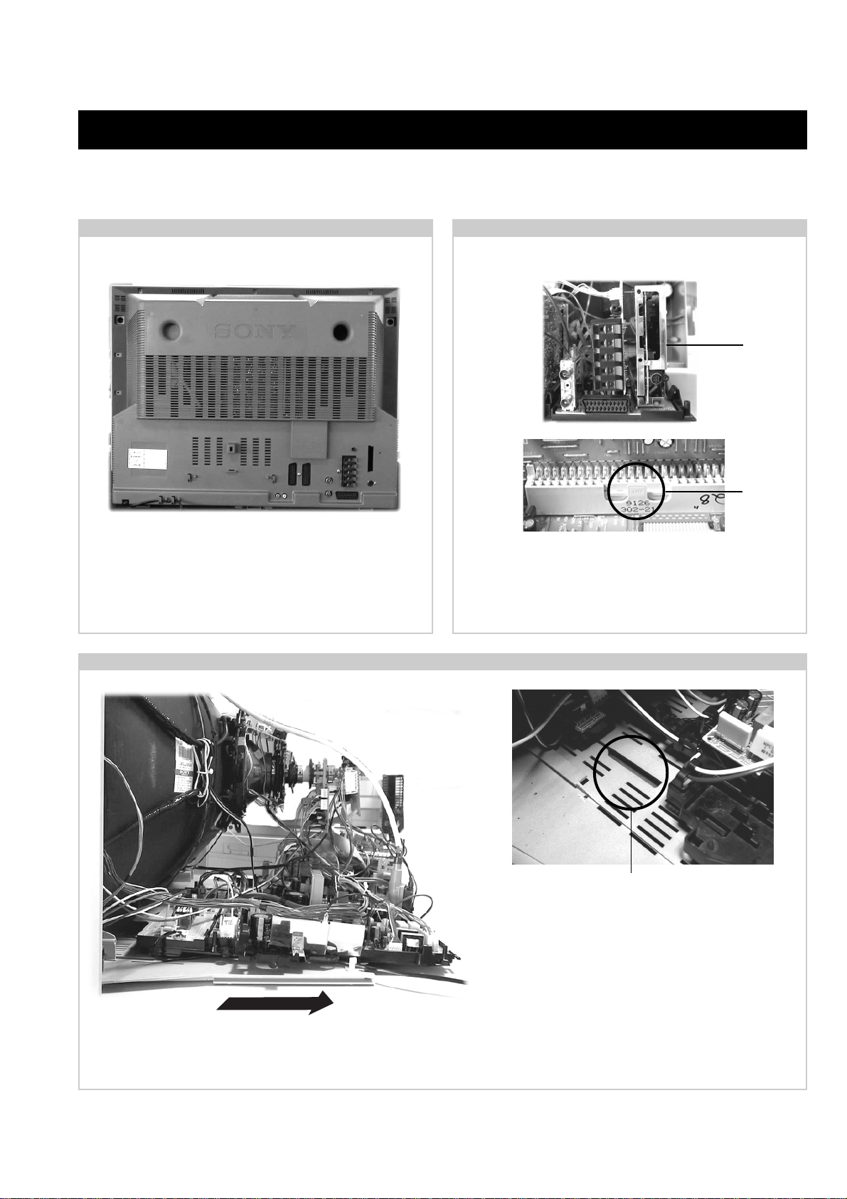
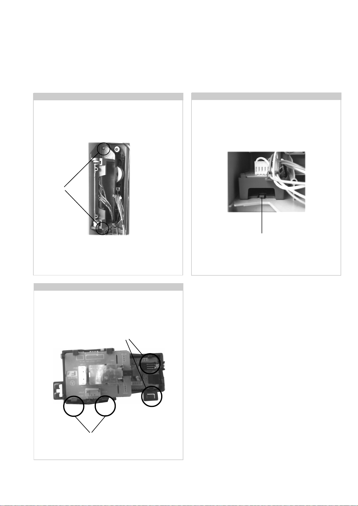
2-1. Rear Cover Removal
<=
<=
=>
=>
=>
=>
Remove the rear cover f ixing screws indicated. Take care
when removing the rear cover not to damage the speaker
cables [Disconnect the speaker connector] as speakers are
fitted inside the rear cover .
<=
<=
2-3. N Board Removal
<=
Shield
Case
<=
Clip
T o remov e the N Board f irst pull the shield case sho wn
vertically . The clip circled can then be released and the board
gently removed.
2-2. Chassis Removal and Refitting
T o remove lift the main bracket rear slightly and slide the
chassis away from the beznet. Ensure that the interconnecting
leads are released from their purse locks to prevent damage
being caused.
When refitting the chassis ensure that the main
bracket is located in the beznet guide slots before
sliding the chassis forwards. Refit the
interconnecting leads in their respective purse locks.
15
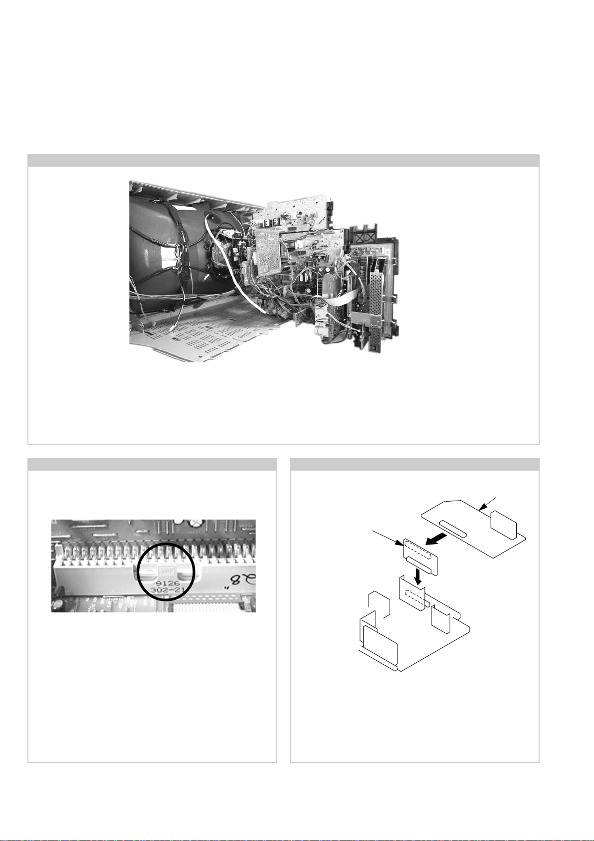
2-4. Service Position
Position the chassis as indicated to access the solder side. T o gain access to the D Board follo w the instructions on page 19. [Remov al and
Replacement of the main bracket bottom plates ].
2-5. A Board Removal
T o remove the A Board release the clip circled and gently
remove the board in a vertical direction.
2-6. A Extension Board
A board
BE-3E Extension Board
T o gain test access to the A Board remov e the board and plug in
the extension board. The A board can then be plugged into the
extension board to allow testing.
16
2-7. Side Control Module Removal
Remove the two screws fixing the user control module to the
side of the set. The control module can then be removed by
sliding it towards the rear of the set allowing access to the H7
Board.
Screws
2-8. F4 Bracket Removal
Release the clip circled and pull the bracket towards the rear of
the set. The bracket can then be removed to allow access to the
boards.
Clip
2-9. F4 and H8 Board Removal
T o remove the F4 and H8 Boards release the clips circled and
ease the boards gently away from the support bracket.
Clips
Clips
17
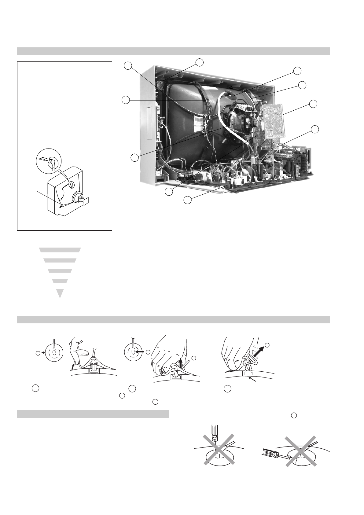
3LFWXUH 7XEH 5HPRYDO
WARNING:
BEFORE REMOVING
THE ANODE CAP
High voltage remains in the CRT even
after the power is disconnected. To
avoid electric shock, discharge CRT
before attempting to remove the anode
cap. Short between anode and CRT
coated earth ground strap.
Coated Earth
Ground Strap
8
10
1
9
7
3
2
6
5
4
1. Discharge the anode of the CR T and remove the anode cap.
2. Unplug all interconnecting leads from the Deflection yoke, neck
assy, de gaussing coils and CRT grounding strap.
3. Remove the C Board from the CR T.
4. Remove the chassis assembly .
5. Loosen the Neck assembly fixing screw and remove.
6. Loosen the Deflection yoke fixing screw and remove.
7. Place the set with the CRT f ace down on a cushion and remov e
the Degaussing Coil holders.
8. Remove the Degaussing Coils.
9. Remove the CR T grounding strap and spring tentioners.
10. Unscrew the four CRT fixing screws [ located on each CRT
corner ] and remove the CR T .
[T ake care not to handle the CR T by the neck.]
5HPRYDO RI WKH $QRGH&DS
* REMOVING PROCEDURES.
a
1
Turn up one side of the rubber cap in
the direction indicated by the arrow a
b
2 Using a thumb pull up the rubber cap
firmly in the direction indicated by the
arrow b
+RZ WR KDQGOH WKH $QRGH&DS
1. To prevent damaging the surface of the anode-cap do not use
sharp materials.
2. Do not apply too great a pressure on the rubber, as this may cause
damage to the anode connector.
3. A metal fitting called a shatter hook terminal is fitted inside the
rubber cap.
4. Do not turn the rubber foot over excessively, this may cause damage
if the shatter hook sticks out.
c
b
Anode button
3 When one side of the rubber cap is
separated from the anode button, the
anode-cap can be removed by turning
up the rubber cap and pulling it up in
the direction of the arrow c
18
ATTENTION
4
ATTENTION
other
4
Fig 4
AFTER CUTTING AWAY FOR THE SAFETY REASON.
THIS PLATE MUST BE REMOVED
Catch
3
44
1
2
2
FOR SAFETY REASONS
AFTER CUTTING AWAY
(TURN 180' NOT FLIP OVER)
THIS PLATE MUST BE REMOVED
ATTENTION
Tab
NUMERICAL MARKINGS
.
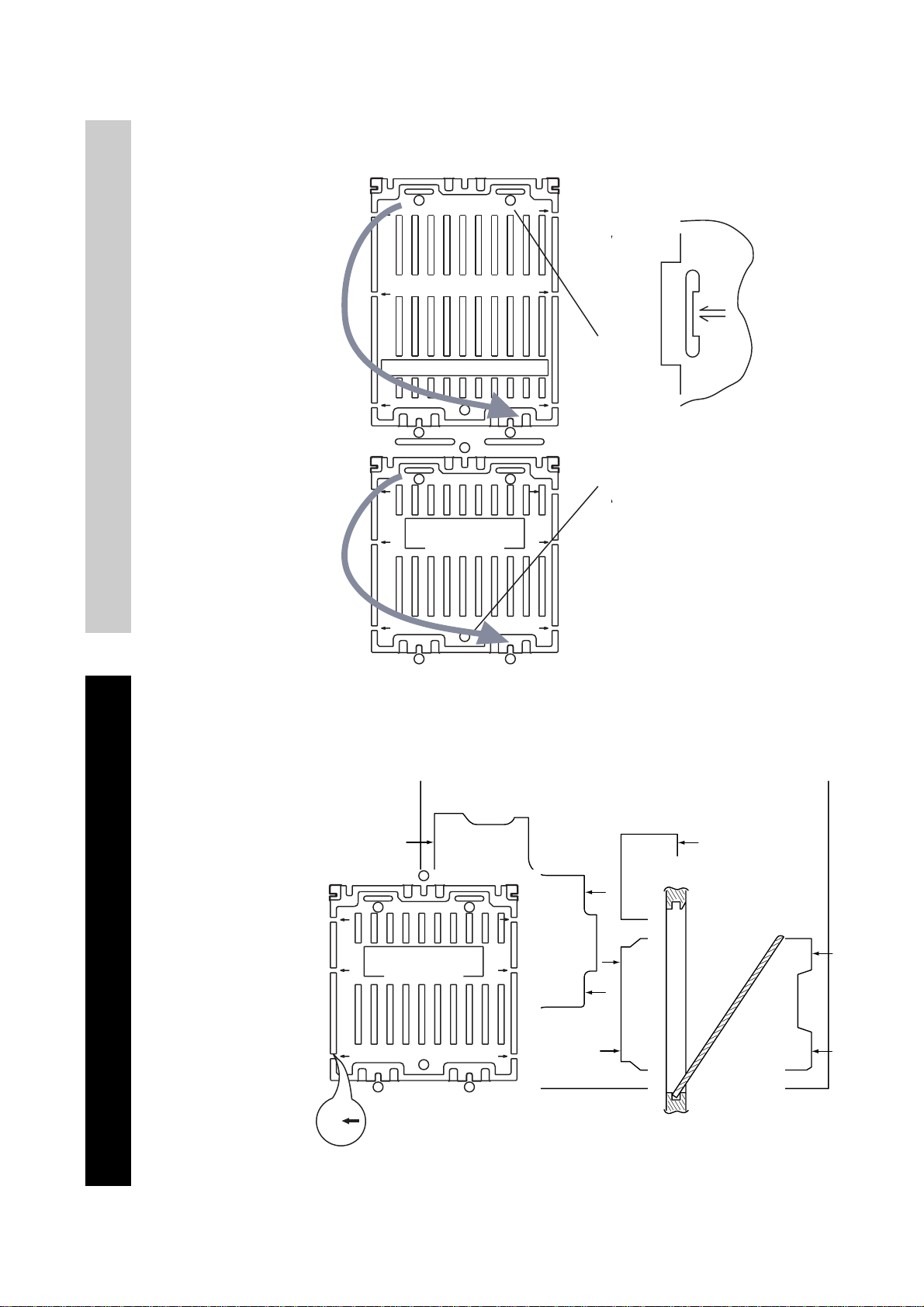
For safety reasons, on no account should the plates be
removed and not refitted after servicing.
REFITTING REFITTING
£
Because the plates differ in size it is important that the correct plates are refitted in their original
location.
Please note that the plates need to be rotated 180 degrees from their cut position to allow the
(2) REFITTING THE PLATES
tabs to be fitted into their catch positions.
1
22
Fig 2
In the event of the plates requiring to be removed
at a later stage, this can be achieved by inserting a
screwdriver in the snap-recess indicated as in Fig 4
and lifting out.
REMOV AL AND REPLA CEMENT OF THE MAIN-BRACKET
BOTT OM PLA TES.
1
2
1
Only remove the necessary plate to gain access to the printed wiring board.
In the event of servicing being required to the solder side of the D Board printed wiring board,
the bottom plates fitted to the main chassis bracket require to be removed.
This is performed by cutting the gates with a sharp wire cutter at the locations indicated by the
arrows.
(1) REMOVING THE PLATES
Note : There are 4 plates fitted to the main bracket and secured by3 gates.
Cut points
2
FOR SAFETY REASONS
AFTER CUTTING AWAY
(TURN 180' NOT FLIP OVER)
THIS PLATE MUST BE REMOVED
ATTENTION
22
Fig 1
19
MAIN BRACKET
INSERT FROM
THE BOTTOM
FIG 3
SIDE
SECTION 3 SET -UP ADJUSTMENTS
• When complete readjustment is necessary or a new picture tube is
installed, carry out the following adjustments.
• Unless there are specific instructions to the contrary, carry out
these adjustments with the rated power supply .
• Unless there are specific instructions to the contrary, set the
controls and switches to the following settings :
Contrast .................................. normal
Brightness .................................. normal
3-1. Beam Landing
Preparation :
1. In order to reduce the influence of geomagnetism on the set’s
picture tube, face it in an easterly or westerly direction.
2. Switch on the TV set’s power and degauss with a de g ausser .
(1) Adjustment of Correction Magnet for Y-Splitting Axis.
1. Input a crosshatch signal from the pattern generator.
2. Set the Picture control to minimum and confirm that the
Brightness control is set to normal.
3. Position the neck assembly as indicated in Fig.3-3.
4. Loosen the deflection yoke fixing screw .
5. Move the deflection yoke as far forward as is possible.
6. Adjust the upper and lower pin symmetrically by opening or
closing the Y -splitting axis cor rection magnets located on the neck
assembly. [See Fig 3-1 and Fig 3-2]
7. Return the deflection yoke to its original position and re-tighten its
fixing screw.
Fig.3-1
Y-splitting axis correction magnet
Carry out the adjustments in the following order :
3-1. Beam Landing.
3-2. Convergence.
3-3. Focus.
3-4. White Balance.
Note : Test equipment required.
1. Color bar/pattern generator.
2. Degausser.
3. Oscilloscope.
4. Digital multimeter.
Caution :
High voltages are present on the Deflection yoke terminals - take care
when handling the Deflection yoke whilst carrying out adjustments.
(2) Landing
Note : Before carrying out the following adjustments adjust the
magnets as indicated below [See Fig.3-4].
1. Input a crosshatch signal from the signal generator.
2. Rough-adjust the focus and horizontal convergence.
3. Switch from the crosshatch pattern to an all-red pattern.
4. Move the deflection yoke backwards and adjust with the purity
magnet so that the red is at the centre and it aligns
symmetrically [See Fig.3-5].
5. Move the deflection yoke forward to the point where the entire
screen just becomes red [Mark its position].
6. Move the deflection yoke further forward until the screen just
changes colour at the edges. [Mark its position]
7. Position the deflection yoke between the two marks indicated
above.
8. Input a crosshatch pattern from the pattern generator and rotate the
deflection yoke so that the horizontal lines are parallel with the top
and bottom of the screen.
9. When the position of the deflection yoke has been determined,
fasten it with its fixing screw.
10. Switch the pattern generator to green then blue and confirm the
purity.
11. If the beam does not land correctly in all the corners of the screen,
use disk magnets to correct it. [Confirm the corner landing for
green and blue]
Fig.3-2
20
Fig.3-3
G1
G2
Neck assy
+
G3
Align the edge
of the neck assy with
the edge of the G2 grid
on the G3 side.
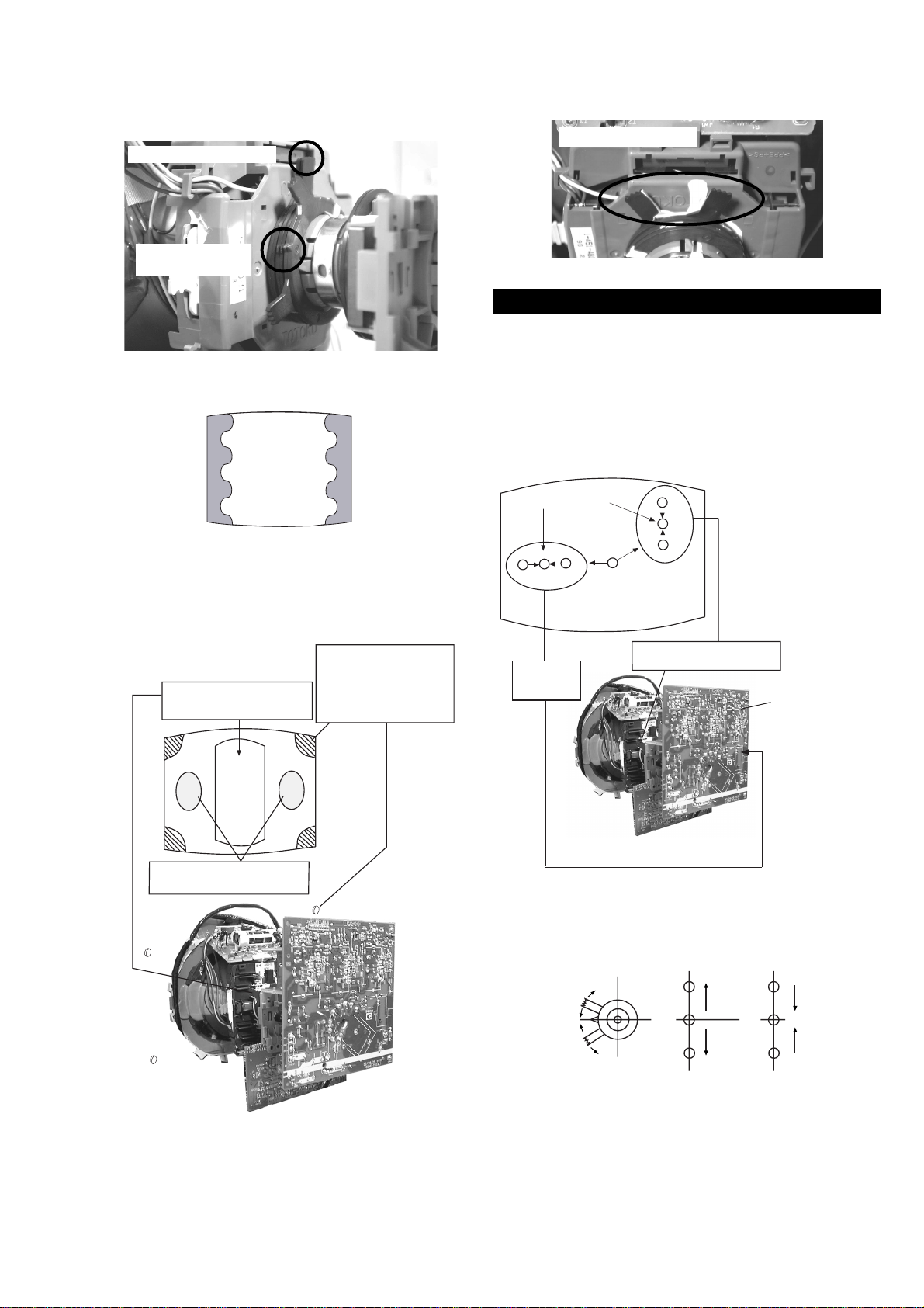
Fig.3-4
Purity magnets
Align pips on
each magnet
GREEN
RED
Align both Purity magnets
to the vertical position
BLUE
Purity control magnets
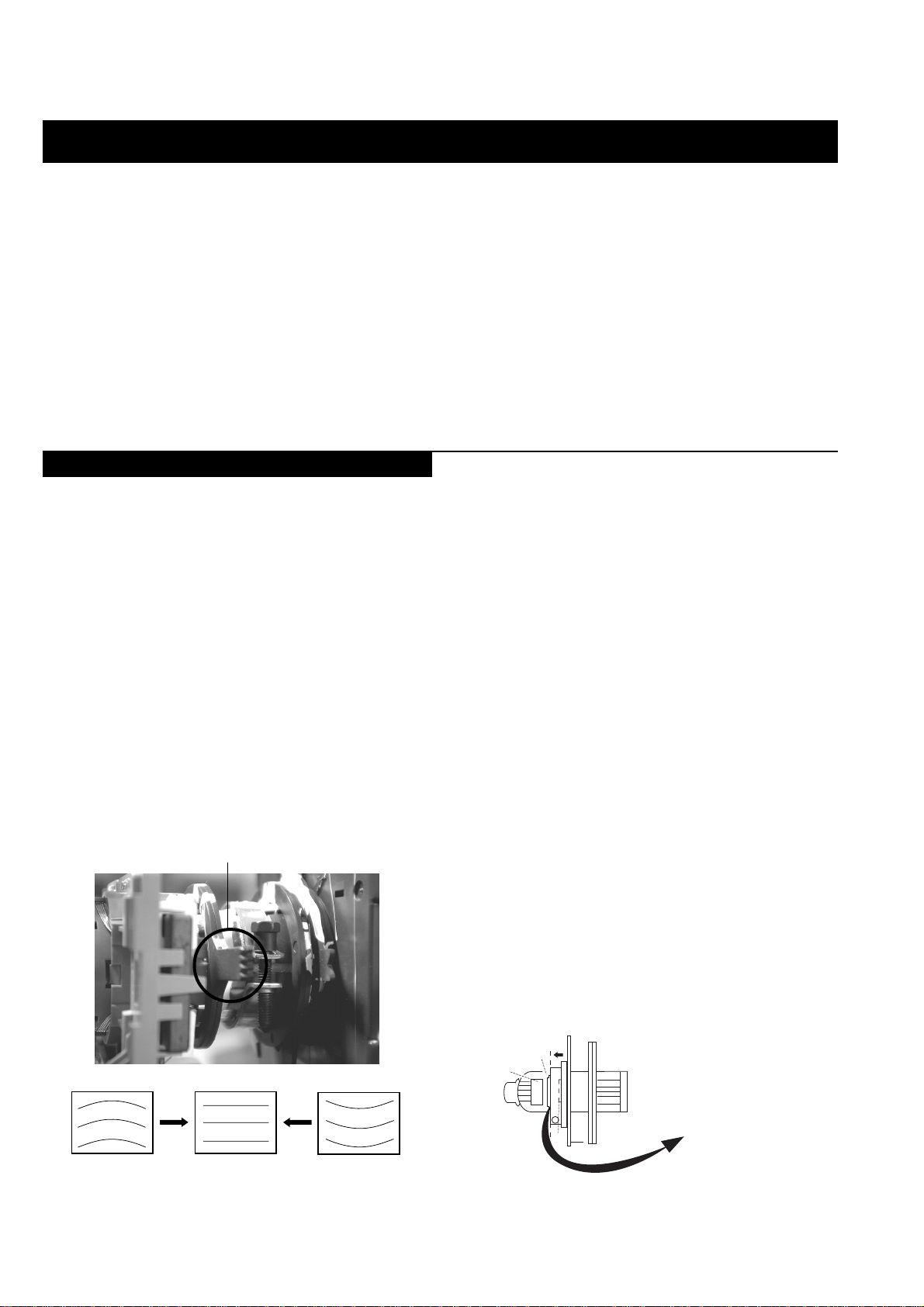
3-2. Con vergence
(1) Screen centre convergence [Static convergence]
1. Input a dot pattern signal from the pattern generator .
2. Normalize the picture setting.
3. [Moving vertically], adjust the V.STAT magnet so that the
vertical red, green and blue dots coincide at the centre of the
screen.
Center dot
R
G
B
)LJ
Disk Magnets
Purity control corrects
this area
a
cd
b
Deflection yoke positioning
corrects these areas
Disk magnets or
rotatable disk
magnets correct
these areas (a-d)
R
G
B
H STAT
convergence
control
V.STAT Vertical Static Magnet
C Board
RV701 (H STAT)
H STAT Convergence
(on mount side)
By opening or closing the V.ST AT magnet, the red green and blue
dots move in the direction indicated below.
B
G
R
B
G
R
Note: Do not adjust the H.STAT by rotating the V.STAT
magnets as this can affect the focus setting.
21
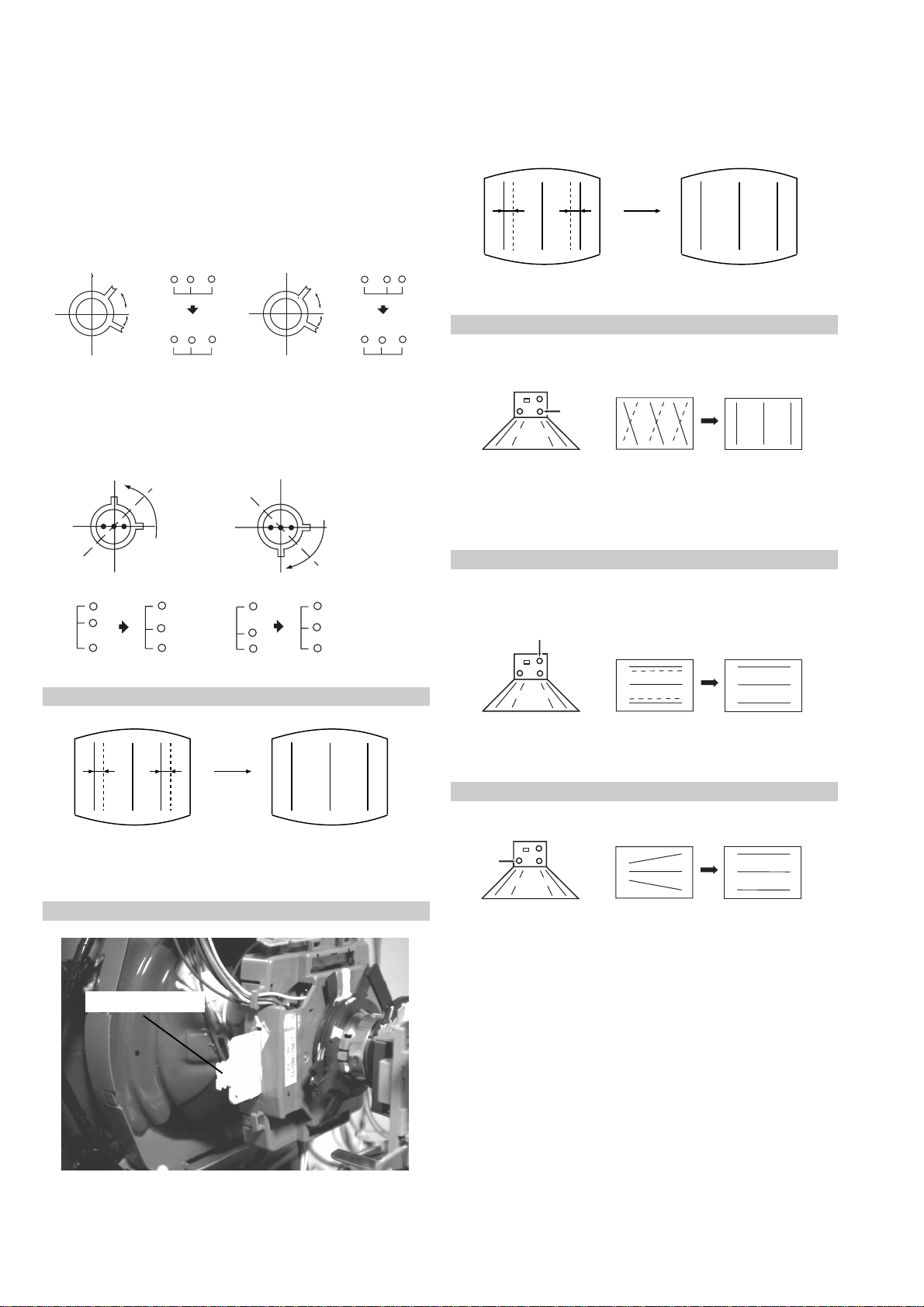
4. Correction for HMC [Horizontal mis-convergence] and VMC
[V ertical mis-con ver gence] by using the BMC [Hexapole] magnet.
a). HMC correction by BMC [Hexapole] magnet and movement of
the electron beam.
HMC correction(A) HMC correction(B)
A > B
A < B
RG B
RGB
HTIL correction can be performed by adding a THL correction
assembly to the Deflection yoke.
A = B
RG B
A = B
RG B
b). VMC correction by BMC [Hexapole] magnet and movement of
the electron beam.
VMC correction(A) VMC correction(B)
C < D
C
D
C = D C > D C = D
R
G
B
R
C
G
D
B
R
G
B
R
G
B
HAMP Adjustment
YCH Adjustment
+
+
+
YCH VR
Deflection Yoke
TL V Adjustment
TLV VR
+
+
+
Deflection Yoke
Adjust the HAMP using HAMPL and HAMPR registers in the
Dynamic Convergence section of the service menu.
HTIL Adjustment
THL Correction assy
H-TRAP Adjustment
+
+
HTRAP VR
+
Deflection Yoke
The H-TRAP should not be adjusted unless absolutely necessary as it
affects the TLV settings.
22
Layout of each control
Purity magnet
BMC (Hexaploe) magnet
V STAT convergence magnet
Y-splitting axis correction magnet
3-3. Focus, Screen (G2) Adjustment
1. Receive a television broadcast signal.
2. Normalize the picture setting.
3. Adjust the focus control located on the flyback transformer to
obtain the best focus at the centre of the screen.
Bring only the centre area of the screen into focus, the magentaring appears on the screen. In this case, adjust the focus to
optimize the screen uniformly.
Note : If you are unable to adjust the corner converg ence properly ,
this can be corrected with the use of permalloy magnets.
a
a-d: screen-corner
convergence defect
c
Install the permalloy assembly
for the area that needs correcting.
b
d
a
b
Permalloy Assy
X-4387-214-1
Focus
Control
Screen
(G2)
G2 adjustment [RV5376]
1. Input a dot signal from the pattern generator.
2. Set the Picture, Brightness and Colour to minimum.
3. Apply 170V DC from an external power supply to the R, G and B
cathodes of the CRT .
4. Whilst watching the picture, adjust the G2 control R V5376
[SCREEN] located on the C Board to the point just before the
flyback return lines disappear.
3-4. White Balance Adjustment
[Adjustment in the service mode using the remote
commander]
White balance adjustment for TV mode
1. Input an all-white signal from the pattern generator.
2. Enter into the ‘Service Mode’ by pressing ‘TEST’, ‘TEST’ and
‘MENU’ on the Service Commander.
3. Select ‘Picture Adjustment’ from the on screen menu display and
press the joystick to the right.
4. The ‘Picture Adjustment’ menu will a ppear on the screen.
[See Page 24]
5. Select ‘Sub Contrast’ and adjust to 7.
6. Adjust the ‘G-Drive’ and the ‘B-Drive’ so that the white
balance becomes optimum.
7. Press the ‘TV’ button on the remote commander to return to TV
operation.
d
Convergence adjustment with permalloy
c
23
SECTION 4
CIRCUIT ADJUSTMENTS
4-1.ELECTRICAL ADJUSTMENTS
Service adjustments to this model can be performed
using the supplied Remote Commander R M- 888.
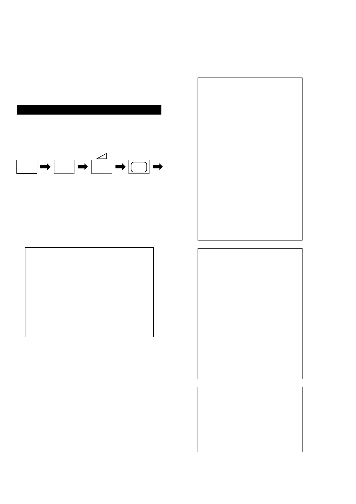
HOW TO ENTER INTO SERVICE MODE
1. Turn on the main power switch and enter into the stand-by
mode.
2. Press the following sequence of buttons on the Remote
Commander.
+
(ON SCREEN
DISPLAY)
• ‘TT--’ will appear in the upper right corner of the
screen.
Other status information will also be displayed.
3. Press ‘MENU’ on the remote commander to obtain the
following menu on the screen.
5
(DIGIT 5) (VOLUME +) (TV)
+
PICTURE ADJUSTMENT
AFC mode 1
REF position 3
SCP BGR 1
SCP BGF 1
Trap fo 9
Sub contrast Adj
Sub colour Adj
Sub brightness Adj
Green drive Adj
Blue drive A dj
Green cutoff Adj
Blue cutoff Adj
Gamma 0
Pre / overshoot 0
Y delay 3
D Pic ON/OFF
D Colour ON/OFF
DC Transfer ON/OFF
TEST MENU
> Picture Adjustment
Geometry
Wide
IC status
MSP
Dynamic Convergence
Current TV status
4. Move to the corresponding adjustment using the button on the
remote commander.
5. Press the + button to enter the selected adjustment.
6. Turn off the power to quit the service mode when adjustments
have been completed.
GEOMETRY ADJUSTMENT - 4:3
V size Adj
V position Adj
S Correction Adj
V Linearity A dj
H size Adj
H position Adj
Pin Amp Adj
Pin Phase Adj
AFC Bow Adj
AFC Angle Adj
EHT V 1
EHT H 0
Lo Corn Pin Adj
Up Corn Pin Adj
WIDE ADJUSTMENT - 4:3
V Aspect 0
V Scroll 25
Upper V Lin 0
Lower V Lin 0
Left Blanking 1
Right Blanking 11
24
IC STA TUS (CXA203452 / CXA2040)
Dynamic Convergence
CXA2034526
H lock 1
IKR 1
V NG 0
X-RAY 0
Colour system 7
CV1 sync 0
CXA2040
Sync sep 0
S1 mode pin 01
S2 mode pin 01
PORT EXPANDER
Power Good 1
TUNER
Tuner status 01101011
TV STATUS BE3E
Text system C TEXT- 2
Dolby Enabled YES
DSP Present NO
Text language set WEST
Menu language set WEST
Destination UK
Ageing DISABLED
Auto Shut Off ENABLED
Size 28/32
Colour trap sw ALL
Velocity mod ON
AFT STATUS
Digital RF YES
Attenuation OFF
Range Adj Off - 42
H stat Adj Off - 63
H amp l Adj Off - 63
H amp r Adj Off - 63
Up Y Adj Off - 63
Low Y A dj Off - 63
Y up l Adj Off - 63
Y up r Adj Off - 63
Y low l Adj Off - 63
Y low r Adj Off - 63
Mbow up l Adj Off - 63
Mbow up r Adj Off - 63
Mbow low l A d j Off - 63
Mbow low r Adj Off - 63
V Stat Ad j Off - 63
SUB BRIGHTNESS ADJUSTMENT
1. Input a Phillips pattern.
2. Set the picture control to minimum.
3. Enter into the ‘Picture Adjustment’ service menu.
4. Adjust the ‘Sub-Brightness’ data so that there is barely a
difference between the 0 IRE and 10 IRE signal levels.
SUB CONTRAST ADJUSTMENT
1. Input a video that contains a small 100% area on a black
background.
2. Set the picture control to maximum.
3. Connect an oscilloscope to Pin 3 of CN301 [A Board].
4. Enter into the ‘Picture Adjustment’ service menu.
5. Adjust the ‘Sub-contrast’ data to obtain a black to white
amplitude of 2.20V.
SUB COLOUR ADJUSTMENT
1. Receive a PAL colour bar video signal.
2. Connect an oscilloscope to Pin 3 of CN301 [A Board].
3. Enter into the ‘Picture Adjustment’ service menu.
4. Adjust the ‘Sub-colour’ data so th at the Cyan, Magenta and
Blue colour bars are of equal height as indicated below.
Same Level
Micro/Jungle SDA30C263/MSP3452
B-Out Wavef orm
Note: The data indicated in the ‘TV STATUS’ table is
dependant on destination, screen size and country.
25
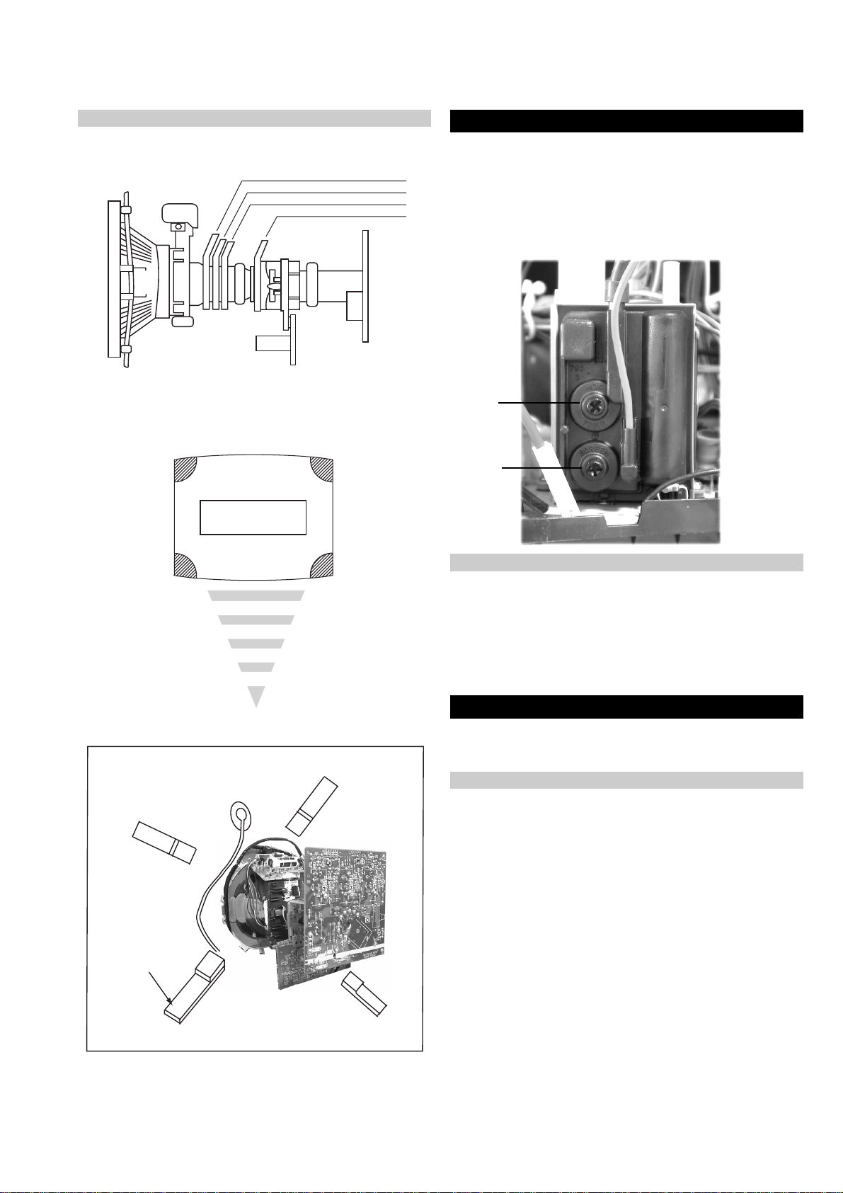
I.F ADJUSTMENT
1. Input an off air signal of between 60-100dBuV / 75 ohm
terminated, via the tuner socket.
2. Enter into the ‘IF Adjustment’ service mode [i.e ‘TT59’] to f ix
the I.F frequency to 39.9MHz.
3. Enter into the service mode and select ‘Current TV status’.
4. Adjust the I.F coil [LV01] until the ‘AFT Status’ indicates a
‘Window’ condition.
STUNER AGC ADJUSTMENT
1. Receive a signal of 63dBuV / 75 ohm terminated, via the tuner
socket.
2. Measure the voltage at test point 1 [A Board].
3. Adjust RV01 control to obtain a voltage of 3.0V +/- 0.3V.
LV01 RV01
TP1
A
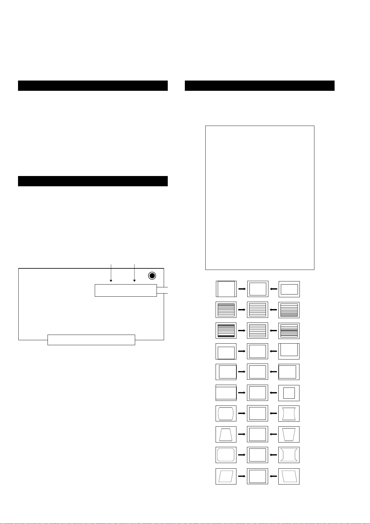
DEFLECTION SYSTEM ADJUSTMENT
1. Enter into the ‘Geometry Adjustment’ service menu.
2. Select and adjust each item in order to obtain the optimum
image.
GEOMETRY ADJUSTMENT
V size Adj
V position Adj
S Correction Adj
V Linearity A dj
H size Adj
H position Adj
Pin Amp Adj
Pin Phase Adj
AFC Bow Adj
AFC Angle Adj
EHT V 1
EHT H 0
Lo Corn Pin Adj
Up Corn Pin Adj
TUNER / IF
V SIZE
V LIN
S CORRECTION
V CENTRE
H SHIFT
H SIZE
PIN AMP
TILT
CORNER PIN
26
V ANGLE
 Loading...