

Sony FD Trinitron KV-28DS65U, FD Trinitron KV-32DS65U Service Manual
1
SERVICE MANUAL GE-1A CHASSIS
MODEL COMMANDER DEST CHASSIS NO. MODEL COMMANDER DEST CHASSIS NO.
KV-28DS65U
RM-892 UK SCC-Q71D-A
KV-32DS65U
RM-892 UK SCC-Q71C-A
®
TRINITRON
®
COLOR TV

2
TABLE OF CONTENTS
CAUTION
SHORT CIRCUIT THE ANODE OF THE PICTURE TUBE AND THE
ANODE CAP TO THE METAL CHASSIS, CRT SHIELD, OR THE
CARBON PAINTED ON THE CRT, AFTER REMOVAL OF THE
ANODE CAP
WARNING !!
AN ISOLATING TRANSFORMER SHOULD BE USED DURING ANY
SERVICE WORK TO AVOID POSSIB L E SHOCK HAZA RD DUE TO
LIVE CHASSIS. THE CHASSIS OF THIS RECEIVER IS DIRECTLY
CONNECTED TO THE POWER LINE.
SAFETY-RELATED COMPONENT WARNING !!
COMPONENTS IDENTIFIED BY SHADING AND MARKED ON
THE SCHEMATIC DIAGRAMS, EXPLODED VIEWS AND IN THE
PARTS LIST AR E CRITICAL FOR SA FE OPERATION. REPLACE
THESE COMPON ENTS WITH SONY PARTS WHOSE PART
NUMBERS APPEAR AS SH OWN IN T HIS MANUAL OR IN
SUPPLEMENTS PUB L IS H ED BY SONY.
ATTENTION
APRES AVOIR DECONNECTE LE CAP DE’LANODE,
COURT-CIRCUITER L’ANODE DU TUBE CATHODIQUE ET
CELUI DE L’ANODE DU CAP AU CHASSIS METALLIQUE
DE L’APPAREIL, OU AU COUCHE DE CARBONE PEINTE
SUR LE TUBE CATHODIQUE OU AU BLINDAGE DU TUBE
CATHODIQUE.
ATTENTION !!
AFIN D’EVITER TOUT RIS QUE D’ELECTROCUTION
PROVENANT D’UN CHÁSSIS SOUS TENTION, UN
TRANSFORMATEUR D’ISOLEMENT DOIT ETRE UTILISÈ LORS
DE TOUT DÈPANNAGE. LE CHÁSSIS DE CE RÈCEPTEUR EST
DIRECTMENT RACCORDÈ Á L’ALIMENTATION SECTEUR.
ATTENTION AUX COMPOSANTS RELATIFS Á
LA SÈCURITÈ !!
LES COMPOSANTS IDEN T IF I ÈS PAR UN E T R AM E ET PAR UNE
MARQUE SUR LES SCHÈMAS DE PRINCIPE, LES VUES
EXPLOSÈES ET LES LIS T ES D E PIECES SONT D’UNE IMPO R
TANCE CRITIQUE POUR LA SÈCURITÈ DU FONCTIONNEMENT,
NE LES REMPLACER QUE PAR DES COMPSANTS SONY DONT
LE NUMÈRO DE PIÈCE EST INDIQUÈ DANS LE PRÈSENT
MANUEL OU DANS DES SUPPLÈMENTS PUBLIÈS PAR SONY.
Section Title Page Section Title Page
Specifications .....................3
W arnin g a nd Cauti on .....................4
Connectors .....................5
Self-Diagnostic Function .....................6
1. GENERAL
Quick Start Guide .....................9
Overview .....................10
Additional TV Features .....................11
Teletext .....................17
Event Schedule Guid e .....................19
Specifications .....................20
Troubleshooting .....................20
2. DISASSEMBLY
2-1. Rear Cover Removal .....................21
2-2. Chassis Assy Removal .....................21
2-3. Service Position .....................21
2-4. A1 Board Removal .....................21
2-5. J Board Removal .....................22
2-6. B Board Removal .....................22
2-7. D1 Board Removal .....................22
2-8. H Bracket Removal .....................22
2-9. Picture Tube Removal .....................23
3. SET-UP ADJUSTMENTS
3-1. Beam Landing .....................24
3-2. Convergence .....................25
3-3. Focus .....................27
3-4. Screen [G2] White Balance .....................27
4. CIRCUIT ADJUSTMENTS
4-1. Electrical Adjustments .....................29
4-3. Test Mode 2 .....................31
5. DIAGRAMS
5-1. Block Diagram (1) .....................33
Block Diagram (2) .....................35
Block Diagram (3) .....................37
Block Diagram (4) .....................39
Block Diagram (5) .....................41
Block Diagram (6) .....................43
Block Diagram (7) .....................45
Block Diagram (8) .....................47
5-2. Circuit Board Location .....................49
5-3. Schematic Diagrams and
Printed Wiring Boards .....................49
* C Board .....................51
* H Board .....................53
* D2 Board ..................... 53
* A Board .....................59
* B Board .....................68
* A1 Board ..................... 77
* D Board .....................83
* D1 Board ..................... 86
* N Board .....................93
* F1 Board .....................105
* VM Board .....................105
* J Board .....................108
5-4. Semiconductors .....................111
5-5. IC Blocks .....................114
6. EXPLODED VIEWS
6-1. Chassis .....................116
6-2. Picture Tube .....................117
7. ELECTRICAL PARTS LIST .....................118
3
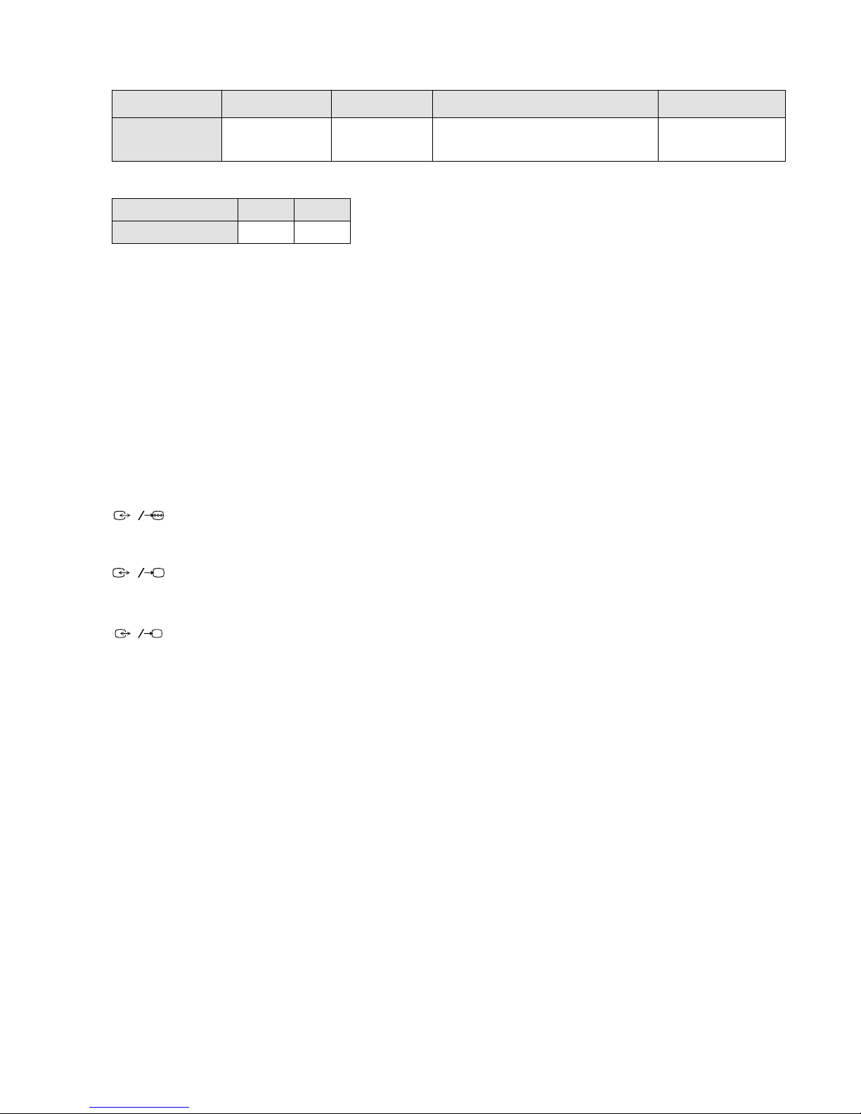
ITEM MODEL Television System Stereo System Channel Coverage Color System
UK I NICAM Stereo UHF : B21-B69
PAL
NTSC4.43, NTSC3.58
(VIDEO IN)
MODEL 28DS65U 32DS65U
Power Consumption 200W 200W
[PICTURE TUBE]
KV-28DS65 FD Trinitron WIDE
Approx. 71 cm (28 inches)
(Approx. 66cm picture measured
diagonally)
102 degree deflection
KV-32DS65 FD Trinitron WIDE
Approx. 82 cm (32 inches)
(Approx. 76 cm picture measured
diagonally)
102 degree deflection
Input/Output Terminals
[REAR]
21-pin Euro connector (CENELEC standard).
- Inputs for Au dio and Video signals.
- Inputs for R GB.
- Outputs of T V Video and Audio signals.
21-pin Euro connector
- Inputs for Au dio and Video signals.
- Inputs for S video.
- Outputs forVideo and Audio signals (selectable).
21-pin Euro connector
- Inputs for Au dio and Video signals.
- Inputs for S video.
[FRONT]
3 Video output - phono jack
3 Audio inputs - phono jacks
3 S Video input - 4 pin DIN
Headphone jack : stereo mini jack
Sound output 2x30W (Music Power)
Power requirements 220 - 240V
Dimensions
KV- 28DS65 Approx 773 x 501 x 526 mm (w/h/d)
KV- 32DS65 Approx 867 x 564 x 558 mm (w/h/d)
Weight
KV- 28DS65 Approx 56.5kg
KV- 32DS65 Approx 68.5kg
Supplied accessories RM-892 Remote Commander (1)
IEC designated R6 batteries (2)
Other features NICAM, DNR, Dolby Digital
Surround System, Graphic Equalizer,
TELETEXT, Smartlink
[RM-892]
Remote control system Infrared control
Power requirements 3V dc
2 batteries IEC designation
R6 (size AA)
Dimensions Approx 210x56x24mm (w/h/d)
Weight Approx 110g (Not includin g battery)
Design and specifications are subject to change without notice.
1
2
S
3
S
4
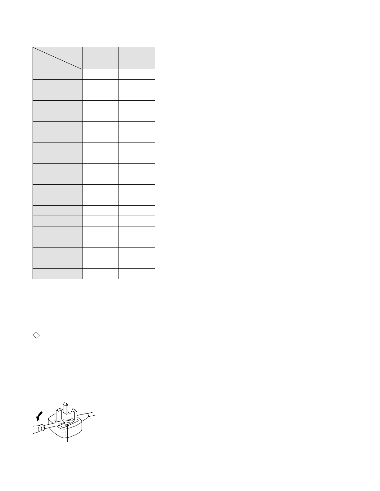
WARNING
The flexible mains lead is supplied connected to a B.S. 1363 fused plug
having a fuse of 5 AMP capacity. Should the fuse need to be replaced,
use a 5 AMP FUSE approved by ASTA to BS 1362, ie one that carries the
mark.
IF THE PLUG SUPPLIED WITH THIS APPLIANCE IS NOT SUIT ABLE
FOR THE OUTLET SOCKETS IN YOUR HOME, IT SHOULD BE CUT
OFF AND AN APPROPRIATE PLUG FITTED. THE PLUG SEVERED
FROM THE MAINS LEAD MUST BE DESTROYED AS A PLUG WITH
BARED WIRES IS DANGEROUS IF ENGAGED IN A LIVE OUTLET
SOCKET.
When an alternative type of plug is used it should be fitted with a 5 AMP
FUSE, otherwise the circuit should be protected by a 5 AMP FUSE at the
distribution board.
ASA
T
How to replace the fuse.
Open the fuse compartment with
a screwdriver blade and replace
the fuse.
FUSE
Model N am e
Item
KV-28DS65U KV-32DS65U
Pal Com b ON ON
PIP OFF OFF
RGB Priority ON ON
Woofer Box ON ON
Scart 1 ON ON
Scart 2 ON ON
Front in (3) ON ON
Scart 4 ON ON
Projector OFF OFF
AKB in 16:9 mode ON ON
Norm B/G OFF OFF
Norm I ON ON
Norm D/K OFF OFF
Norm AUS OFF OFF
Norm L OFF OFF
Norm SAT OFF OFF
Norm M OFF OFF
Teletext ON ON
Nicam Stereo ON ON
Language Preset English English
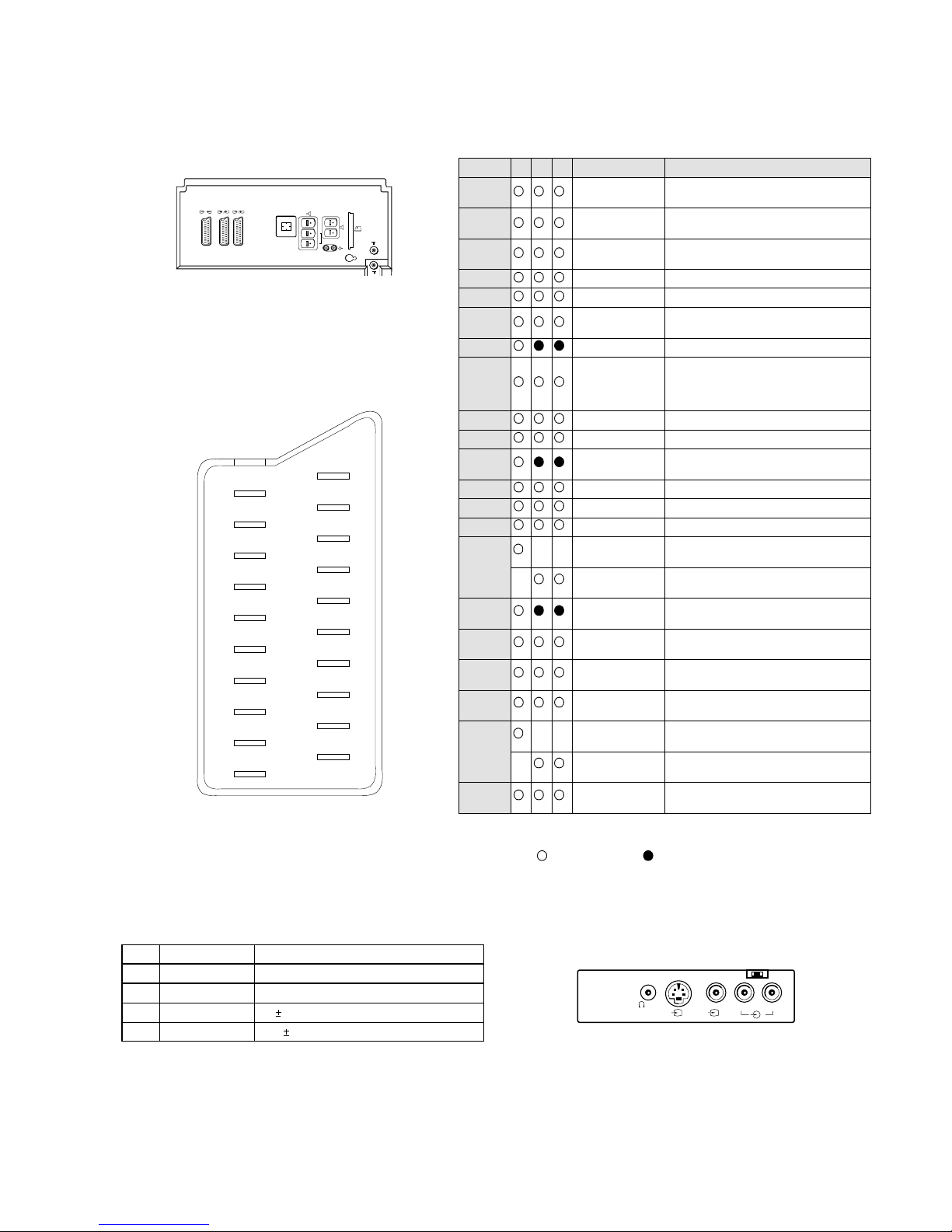
5
21 pin connector
Connected Not Connected (open) * at 20Hz - 20kHz
Pin No 1 2 4 Signal Signal level
1 Audio output B
(right)
Standard level : 0.5V rms
Output impedence : Less than 1kohm*
2
Audio output B
(right)
Standard level : 0.5V rms
Output impedence : More than 10kohm*
3
Audio output A
(left)
Standard level : 0.5V rms
Output impedence : Less than 1kohm*
4 Ground (audio)
5 Ground (blue)
6 Audio input A
(left)
Standard level : 0.5V rms
Output impedence : More than 10kohm*
7 Blue input 0.7 +/- 3dB, 75 ohms positive
8 Function select
(AV control)
High state (9.5-12V) : Part mode
Low state (0-2V) : TV mode
Input impedence : More than 10K ohms
Input capacitance : Less than 2nF
9 Ground (green)
10 Open
11 Green Green signal : 0.7 +/- 3dB, 75 ohms,
positive
12 Open
13 Ground (red)
14 Ground (blanking)
15
_ _ Red input 0.7 +/- 3dB, 75 ohms, positive
_ (S signal Chroma
input)
0.3 +/- 3dB, 75 ohms, positive
16 Blanking input
(Ys signal)
High state (1-3V) Low state (0-0.4V)
Input impedence : 75 ohms
17 Ground (v ideo
output)
18 Ground (v ideo
input)
19 Video output 1V +/- 3dB, 75ohms, positive sync 0.3V
(-3+10dB)
20
_ _ Video input 1V +/- 3dB, 75ohms, positive sync 0.3V
(-3+10dB)
_ Video input
Y (S signal)
1V +/- 3dB, 75ohms, positive sync 0.3V
(-3+10dB)
21 Common g round
(plug, shield)
R/D/D/D
L/G/S/I
2
S
2
1
4
S
4
1/
R/D/
D/D
L/G/
S/I
C
S
S
MODEM
....
L/G/S/I R/D/D/D
S
3
3
3
19
17
15
13
11
9
7
5
3
1
20
18
16
14
12
10
8
6
4
2
21
Signal
Ground
Ground
Y (S signal) input
C (S signal) input
Pin No.
1
2
3
4
Signal Level
1V 3dB 75 ohm, positive Sync. 0.3V -3 + 10dB
0.3V 3dB 75 ohm, positive Sync.
6
GE-1A SELF DIAGNOSTIC SOFTWARE
The identification of errors within the GE-1A chassis is triggered in one of two ways :- 1: Busy or 2: Device failure to respond to IIC. In the
event of one of these situations arisin g the softwa re will f irst try to re lease the b us if busy (F ail ure to do so will report with continuous flashing
LED) and then communicate with each device in turn to establish if a device is faulty. If a device is found to be faulty the relevant device
number will be displayed through the LED (Series of flashes which must be counted) See table 1., non fatal errors are reported using this
method.
ERROR
LED
ERROR
COUNT
No error 00
Not allowed (may be confused with Sircs response
flash!)
01
Over Current Protection 02
Over Voltage Protection 03
Vertical Protection 04
No function 05
H - Protection 06
Speaker Protection 07
MEGATEXT 08
NVM 09
Main colour decoder 10
Feature Box 1 11
D/A converter 12
Multi Component processor 13
Multi sound processor 14
DMUX 15
Feature Box 2 16
StBy LED
ON ON ON
OFF OFF
Flash Tim ing Example : e.g. error number 3
Diagnostic Item
Description
No of times Standby
LED Flashes
Probable cause
Location
Detected Symptoms
Power does not turn on Does not light Power cord is not plugged in
Fuse is burned out
Power does not come on
No power is supplied to the TV
AC power supply is faulty
+B Overvoltage(OVP) 2 times H.OUT (Q502) is shorted. (D Board)
IC603 Power IC is shorted. (D Board)
Power does not come on
Load on power line has shorted
Vertical Deflection stopped 4 times +15V is not supplied R519 open (D Board)
-15V is not supplied R518 open (D Board)
IC502 is shorted (D Board)
Vertical deflection pulse has stopped
Power line has shorted

7
ERROR DETECTION MONITOR
Device acknowledge is used to check IIC errors. Device acknowledge is checked by sending an IIC start sequence during CRT power on. Each
device is checked three times, if there is no acknowledge after every attempt, it will be regarded as an error.
There are three steps to check errors
1. IIC line 0
If all devices except the NVM are errors, IIC line 0 error is displayed
2. Board che ck
If all devices mounted on one boar d have error s , board error is displayed
3. Each device check
If IIC line error and board error are not detected then the device with an error is displayed
The detected errors can be display ed as fol lows:
1. Error Monitor Menu
2. Error Reader
1. ERROR MONITOR MENU
The error monitor menu is displayed by selecting TT22. The following menu will be displayed:
ERROR MONITOR
Operating Time :
930360h 15h
Saved Errors :
1. 000h = B-Board
2. 000h = P87C654-Feature Box *B
3. 000h = no error occured
4. 000h = no error occured
5. 000h = no error occured
Actual Error :
New error code sequence is starting
Ignore Errors : [off]
To reset NVM press TT65

8
2. ERROR READER DISPLAY
The error reader display is connected to the servic e connector to read actual error codes. The part number for the error reader display is
S-188-900-10. Once an error has been detected it will then be displayed on the two digit er r or reader. The errors displayed refer to the
following table :
Send Data to Error Reader
Error Code Data high Data Low Error type Function
00 00h - f0h no device
Gen.IIC Error
00 01h f0h 01h IIC 0 line
00 02h f0h 02h IIC 1 line
Board Error
01 00h f1h 00h A Board
02 00h f2h 00h No function
03 00h f3h 00h B Board
04 00h f4h 00h No function
05 00h f5h 00h D1 Board
06 00h f6h 00h J Board
07 00h f7h 00h Q Board
Device Error
A Board
01 01h f1h 01h ST24C64 NVM doesn’t respond
01 02h f1h 02h SDA5273/75 Megatext doesn’t respond
01 03h f1h 03h CXA2101 MCP
01 04h f1h 04h SDA9361 Deflection doesn’t respond
01 05h f1h 05h TVF-01-XXX Tuner doesn’t respond
01 06h f1h 06h No function
01 07h f1h 07h MSP3410D Audio processor
01 08h f1h 08h CXA1875 Port Expander for SCART doesn’t respo nd
01 09h f1h 09h CXA1315 Port Expander for UYV doesn’t respond
01 10h f1h 10h PCF8574 General Port Expander 1 doesn’t respond
01 11h f1h 11h No function
01 12h f1h 12h PCF8574 Interrupt Port Expander doesn’t respond
01 13h f1h 13h PCF8593 Real Time Clock doesn’t respond
01 14h f1h 14h No function
02 01h f2h 01h TC9337 Audio Effect Processor (DSP) doesn’t respond
B Board
03 01h f3h 01h TDA9144 Colour Decoder doesn’t respond
03 02h f3h 02h No function
03 03h f3h 03h No function
03 04h f3h 04h P87C654 Feature box1 doesn’t respond
03 05h f3h 05h SDA9280 D/A Converter doesn’t respond
03 06h f3h 06h P87C654 Feature box doesn’t respond
D1 Board
05 01h f5h 01h CXA1875 Port expander for MP, S-C ont doesn’t respond
J Board
06 01h f6h 01h CXA1855 AV-Switch Doesn’t respond
06 02h f6h 02h TDA7309 Headphone processor doesn’t respond
9
The operating instructions mentioned here are partial abstracts
from the Operating Manual. The page numbers of the Operatng
Instruction Manual remain as in the manual.
9
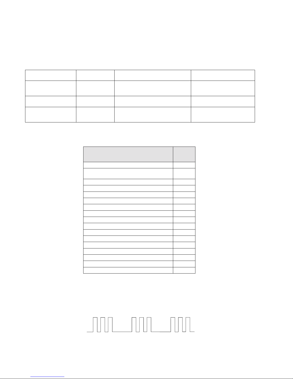
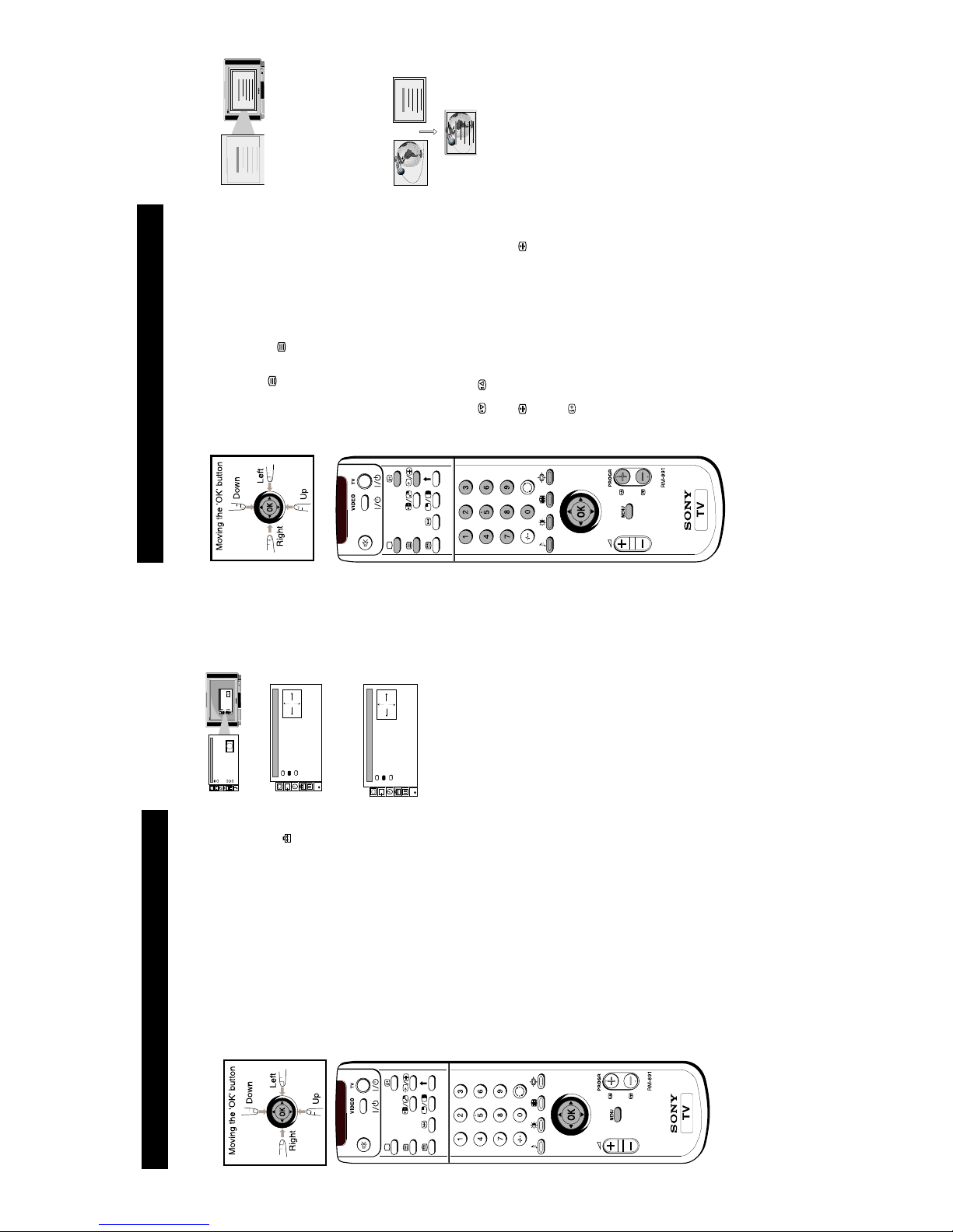
6. Automatically Tuning the TV
1 Press the MENU button on the remote control to display
the menu on the TV screen.
2 Move the OK button on the remote control DOWN to
select the
symbol on the menu screen then move
RIGHT to enter the `PRESET' menu.
3 Move the OK button DOWN to select “Programme
Setup” then move RIGHT to enter the `PROGRAMME
SETUP' menu.
4 Move the OK button RIGHT to highlight the brackets
then move repeatedly DOWN to select `Digital' if you
wish to view digital channels or `Analogue' if you wish
to view analogue channels.
5 Press the OK button to confirm then move LEFT to
display the PRESET menu.
6 Move the OK button UP to select `Auto
Programme' then move the OK button RIGHT to display
the “AUTO PROGRAMME” menu.
7 Press the OK button to start the automatic tuning
process. The word `searching' now flashes on the menu
screen and the TV starts to store all available channels.
As the TV is searching, the bottom right corner of the
menu screen displays its progress. Please be patient and
do not press any buttons.
8 When the autotune procedure is complete, the PRESET
menu appears on the screen and the channel currently
being broadcast on programme 1 is displayed.
9 Press the MENU button to remove the `PRESET' menu
from the TV screen. You can now view the channels by
pressing the PROGR+/- or the numbered buttons on the
remote control.
Notes: • If you wish to stop the “Autotune” procedure,
press the OK button then the MENU button on
the remote control.
• If, after tuning is complete, no digital
programme is displayed on the TV, repeat steps
1-9 but select `Analogue' in the Programme
Setup menu screen. When digital programmes
become available in your area, repeat steps 1-9
above and select `Digital' in the Programme
Setup menu screen.
Quick Start Guide
You need to tune the TV to receive channels. By following the instructions below, this TV will
automatically search and store all available channels for you. If at any time when using this
menu you want to return to the normal TV picture, press the MENU button.
Screen Position
SCREEN MODE
Screen Mode
[zoom ]
[ 0 ]
Strobe
Auto 16:9
Correction
[on]
[off]
Screen Position
SCREEN MODE
Screen Mode
[zoom ]
[ 0 ]
Strobe
Auto 16:9
Correction
[on]
[off]
PRESET
Auto Programme
Programme Setup
Manual Programme Preset
Programme Sorting
Parental Lock
Installation
AUTO PROGRAMME
START
Searching
PROG CH SERVICE
10 63 S01
26% complete
PROGRAMME SETUP
Programme Type
[Digital]
PRESET
Auto Programme
Programme Setup
Manual Programme Preset
Programme Sorting
Parental Lock
Installation
PROGRAMME SETUP
Programme Type
[Analogue]
PRESET
Auto Programme
Programme Setup
Manual Programme Preset
Programme Sorting
Parental Lock
Installation
SECTION 1 GENERAL
12
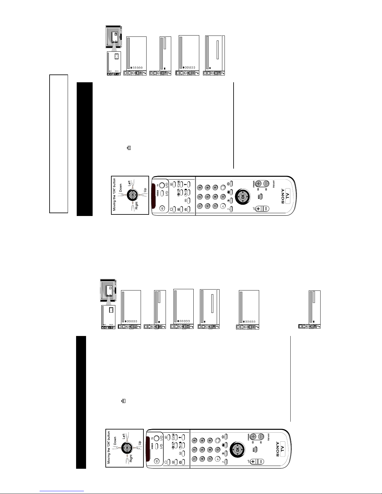
1 Press the MENU button on the remote control to display
the menu on the TV screen.
2 Move the OK button on the remote control DOWN to
select the
symbol on the menu screen then move
RIGHT to enter the `PRESET' menu.
3 Move the OK button DOWN to select “Programme
Setup” then move RIGHT to enter the `PROGRAMME
SETUP' menu.
4 Move the OK button RIGHT to highlight the brackets
then move repeatedly DOWN to select `Digital' if you
wish to view digital channels or `Analogue' if you wish
to view analogue channels.
5 Press the OK button to confirm your selection.
6 You can now view the channels by pressing the
PROGR+/- or the numbered buttons on the
remote control.
Selecting Digital/Analogue Channels via
Remote Control
1 Press the OK button on the remote control to display the
programme table on the TV screen.
2 Push the joystick UP or DOWN to select `Digital/
Analogue' then move RIGHT to enter your option.
3 Move the joystick UP or DOWN to select `Digital' if you
wish to view digital channels or `Analogue' if you wish
to view analogue channels.
Quick Start Guide
You have the option to view either digital channels or analogue channels.
Screen Position
SCREEN MODE
Screen Mode
[zoom ]
[ 0 ]
Strobe
Auto 16:9
Correction
[on]
[off]
Screen Position
SCREEN MODE
Screen Mode
[zoom ]
[ 0 ]
Strobe
Auto 16:9
Correction
[on]
[off]
PRESET
Auto Programme
Programme Setup
Manual Programme Preset
Programme Sorting
Parental Lock
Installation
AUTO PROGRAMME
START
Searching
PROG CH SERVICE
10 63 S01
26% complete
PROGRAMME SETUP
Programme Type
[Digital]
PRESET
Auto Programme
Programme Setup
Manual Programme Preset
Programme Sorting
Parental Lock
Installation
Selecting Analogue or Digital
Channels
Note: This model may be supplied with the RM-892 version commander.
10
11
Overview
Overview of the Remote Control
Buttons
To Mute Sound
Press to mute TV sound. Press again to
restore the sound.
To Select Channels
Press numbered buttons to select channels.
For double-digit programme numbers, e.g. 23,
press -/-- first, then the buttons 2 and 3.
If you enter an incorrect first digit, this should
be corrected by entering another digit (0 - 9)
and then selecting -/-- button again to enter
the programme number of your choice.
To Display Sound Menu
Press to change the sound settings.
Press again to remove the display.
To Adjust TV Volume
Press to adjust the volume of the TV.
To Temporarily Switch Off TV
Press to temporarily switch off TV. Press again
to switch on TV from standby mode.
To save energy we recommend switching off
completely when TV is not in use.
NOTE: After 15 -30 minutes without a TV signal
and without any button being pressed, the TV
switches automatically into standby mode.
To Reveal On Screen Information
Press to reveal all on-screen indications.
Press again to cancel.
To Select Channels
Press to select channels.
To Change Screen Format
Press to change the size of the screen.
To Display Picture Menu
Press to change the picture settings.
Press again to remove the display.
To Select ESG
Press to display the Event Schedule Guide.
Press again to remove display.
To Select Teletext
Press to select Teletext mode.
To Return to TV Mode
Press to return to the normal operation
from teletext mode or standby mode.
VCR On/Off Button
Press to temporarily switch off VCR (if Sony VCR connected).
Press again to switch on VCR.
To Return To Previous Channel
Press to return to the previous channel you were
watching. Note: This can be done only after
watching the present channel for 5 seconds.
To Select Menu Items
Use this OK button to select options
available in the menu system of the TV.
To Display the Time
Open the remote control lid and
press to display the time on screen.
To Operate Video Equipment
Open the remote control lid and press these
buttons to operate your video equipment
(please refer to your VCR manual).
To Control Other Sony Equipment
With this selector you can control other Sony
equipment. Open the remote control lid and
set the selector according to the type of
equipment you want to control then use the
buttons on the remote control to operate the
equipment:
VTR1 : Sony Beta VCR
VTR2 : Sony 8mm VCR
VTR3 : Sony VHS VCR
VTR4 :Sony Digital VCR
MDP : Sony Multi Disc Player
To Reset to Factory Settings
Open the remote control lid and
press to return picture and
sound levels to factory settings.
This button can be used in Teletext mode only.
Please see Teletext section of manual for details.
These buttons have no function.
To Freeze the picture
Press to freeze the picture.
Press again to cancel freeze.
To select input signal or freeze teletext
Press to select inputs from the TV sockets (see
Using Optional Equipment section).
In teletext mode, press to freeze the displayed
page. Press once again to cancel.
To Display the Menu
Press if you wish to use the TV menu system. Press
again to remove the menu from the TV screen.
10
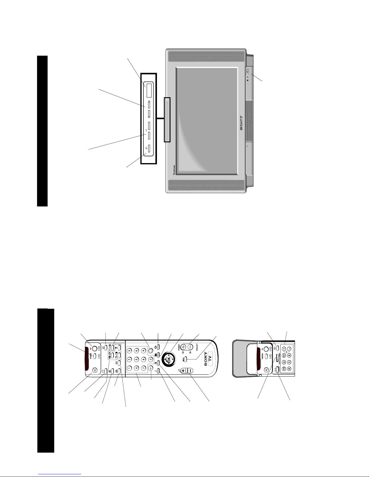
Overview of the TV Set Functions
Overview
CONTROL
+
–
PROGR
–
+
Programme Up (+) or Down
(-) buttons. After pressing
the CONTROL button on the
top of the TV set, press to
select TV channels.
Volume control buttons. After
pressing the CONTROL button
on the top of the TV set, press to
increase (+)/decrease (-) volume.
Video input button.
After pressing the
CONTROL button
on the top of the TV
set, press to select
the input signals
from VCR etc.
On/Off Switch.
Press to switch TV
on/off.
CONTROL button.
Press to activate
and illuminate the
control panel.
11
13
Additional TV Features
Adjusting the Picture
1 Press the MENU button on the remote control to display
the menu on the TV screen.
2 Move the OK button on the remote control DOWN to
select the
symbol on the TV screen then move RIGHT
to display the `PICTURE CONTROL' menu on the TV
screen.
3 Move the OK button UP or DOWN to select the item on
the screen you wish to adjust. For a description of the
menu items and their effects, see the following table.
4 Move the OK button RIGHT to highlight the settings.
5 Adjust the setting by moving the OK button UP,
DOWN, LEFT or RIGHT.
6 As soon as you have adjusted the item, press the OK
button to confirm.
7 Repeat steps 3 to 6 to adjust the other items.
8 Press the MENU button to remove the display from the
TV screen.
Although the picture is adjusted at the factory, you can modify it to suit your own taste.
Picture Control
Item Effect/Operation
Picture Mode Select between the following sound
settings
Personal (for individual settings)
Movie (for films)
Live (for live broadcasts)
Contrast Less More
Brightness* Darker Brighter
Colour* Less More
Hue** Greenish Reddish
Sharpness* Softer Sharper
Reset Resets picture to factory preset levels
AI (Artificial Intelligence) Off:normal
On:rautomatic optimization of
contrast level according to the TV
signal.
Noise Reduction Off:normal
On:reduces picture noise in case of
a weak broadcast signal.
100Hz Mode 1:Normal
2:LFR (Line Flicker Reduction) off
* Only if “Personal“ is selected in `Picture Mode`.
** Available for NTSC colour system only.
Changing Picture and Sound Modes Quickly
You can quickly change the Picture Mode or the Equalizer Mode
without entering the `PICTURE CONTROL` or `SOUND CONTROL`
menu screens.
1 Press the * symbol on the remote control for picture modes or the *
symbol for equalizer modes.
2 Move the OK button on the remote control UP or DOWN to
select the desired mode.
3 Press * or * again to remove the display from the TV screen.
Surround Mode
Hall Effect
Dual Sound
Auto Volume Ctrl.
Volume
Dual Sound
SOUND CONTROL
Equalizer Mode
[Church ]
[A ] NICAM
[Surround ]
[off ]
. . . . . . .
[off ] NICAM
Screen Position
SCREEN MODE
Screen Mode
[zoom ]
[ 0 ]
Strobe
Auto 16:9
Correction
[on]
[off]
Screen Position
SCREEN MODE
Screen Mode
[zoom ]
[ 0 ]
Strobe
Auto 16:9
Correction
[on]
[off]
GRAPHIC EQUALIZER
Mode [ Flat ]
+0-
120 500 1.5k 5k 10k
14
Additional TV Features
Adjusting the Sound
1 Press the MENU button on the remote control to display
the menu on the TV screen.
2 Move the OK button on the remote control DOWN to
select the
symbol on the TV screen then move RIGHT
to enter the `SOUND CONTROL' menu on the TV
screen.
3 Move the OK button UP or DOWN to select the item on
the screen you wish to adjust. For a description of the
menu items and their effects, see the following table.
4 Move the OK button RIGHT to highlight the settings.
5 Adjust the setting by moving the OK button UP,
DOWN, LEFT or RIGHT.
6 As soon as you have adjusted the item, press the OK
button to confirm.
7 Repeat steps 3 to 6 to adjust the other items.
8 Press the MENU button to remove the display from the
TV screen.
Although the sound is adjusted at the factory, you can modify it to suit your own taste.
Sound Control
Item Effect/Operation
Equalizer Mode Select between the following sound settings
Personal
Vocal
Jazz
Rock
Pop
Flat (fixed setting, cannot be adjusted)
Equalizer adjustment You can adjust the mode selected in Equaliser
mode by cutting and boosting the 5 selected
frequency bands. Only the changes made in
Personal can be stored, the others return to
factory setting. Select the desired bar by
moving the OK button UP, DOWN, LEFT or
RIGHT then press the OK button to confirm.
Surround Mode Off
Hall
Pro Logic
*Hall Effect Stadium
Hall
Church
Disco
Dual Sound
•
For a bilingual broadcast:
A for channel 1 B for channel 2
•
For a stereo broadcast:
Stereo Mono
**Auto Volume Control $ On: volume level of the channels will stay
the same independent of the broadcast
signal (e.g. in case of advertisements)
4 Off: volume level changes according to
the broadcast signal
Headphones
2 Volume Less More
2 Dual Sound
•
For a bilingual broadcast:
A for channel 1 B for channel 2•For a stereo broadcast:
Stereo Mono
* Only if “Hall“ is selected in Surround Mode.
** Only if Surround Mode is switched to “off“
Surround Mode
Hall Effect
Dual Sound
Auto Volume Ctrl.
Volume
Dual Sound
SOUND CONTROL
Equalizer Mode
[Church ]
[A ] NICAM
[Surround ]
[off ]
. . . . . . .
[off ] NICAM
Screen Position
SCREEN MODE
Screen Mode
[zoom ]
[ 0 ]
Strobe
Auto 16:9
Correction
[on]
[off]
Screen Position
SCREEN MODE
Screen Mode
[zoom ]
[ 0 ]
Strobe
Auto 16:9
Correction
[on]
[off]
GRAPHIC EQUALIZER
Mode [ Flat ]
+0-
120 500 1.5k 5k 10k
12
15
Setting up Dolby ProLogic
Additional TV Features
Before listening to Dolby Surround sound, you can adapt the Dolby features to suit your own
taste. It is normal to set up the levels and modes of the speakers only when installing the TV
and the speakers or when changing the position of the speakers.
AV Preset
RGB setup
Dolby ProLogic Setup
Picture Rotation
Digital Subtitles
INSTALLATION
Further Prog. Preset
Left
Centre
Right
Surround
DOLBY PROLOGIC SETUP
Level Settings
Speaker Mode [Normal]
Delay Time [20 ms ]
. . . . . . . . .
. . . . . . . . .
. . . . . . . . .
. . . . . . . . .
Auto Surround [off]
1 Press the MENU button on the remote control to display the
menu on the TV screen.
2 Move the OK button on the remote control DOWN to select the
symbol on the TV screen then move to RIGHT to confirm.
3 Move the OK button DOWN to select `Installation` then move
the OK button RIGHT to enter.
4 Move the OK button DOWN to select `Dolby ProLogic Setup`
then move RIGHT to enter.
5 Select `Level Settings` by moving the OK button UP or DOWN.
Move the OK button to RIGHT to enter.
6 Select Left (left speaker), Centre (centre speaker), Right (right
speaker) or Surround (surround speakers)by moving the OK
button DOWN then move the OK button RIGHT to confirm.
7 Adjust the level by moving the OK button RIGHT or LEFT.
8 After you have adjusted the level, press the OK button to
confirm.
9 Repeat steps 6 to 8 if you wish to adjust the sound levels of the
other speakers (from your sitting position the sound output
from all speakers should balance).
10 Move the OK button LEFT.
11 Select `Speaker mode` by moving the OK button DOWN then
move the OK button RIGHT to enter.
12 Push the OK button repeatedly DOWN to select:
Normal – all speakers are activated
3 Wide – surround speakers are not used, centre
speaker carries full frequency response
3 Normal – surround speakers are not used
Wide – wider bandwidth for centre speaker
Phantom – centre speaker is not used
Normal – all speakers are activated
Press the OK button to confirm your choice.
13 Select 'Delay Time' by moving the OK button DOWN then
move to RIGHT to confirm. Adjust the delay time of the surround
speakers by moving the OK button UP or DOWN (e.g 20 ms
for standard rooms, 30 ms for small rooms)
15 ms n 20 ms n 25 ms n 30 ms
Press the OK button to confirm your choice.
14 Select 'Auto Surround' by moving the OK button DOWN then
move to RIGHT to confirm. Move the OK button DOWN to
select:
On - When receiving a Dolby Surround encoded
programme, the TV switches automatically to Dolby
Surround sound (depending on availability of service
by broadcaster).
Off - normal
Press the OK button to confirm your choice.
15 Press the MENU button on the remote control to remove the
menu from the TV screen.
PRESET
Auto Programme
Programme Setup
Manual Programme Preset
Programme Sorting
Parental Lock
Installation
Screen Position
SCREEN MODE
Screen Mode
[zoom ]
[ 0 ]
Strobe
Auto 16:9
Correction
[on]
[off]
Screen Position
SCREEN MODE
Screen Mode
[zoom ]
[ 0 ]
Strobe
Auto 16:9
Correction
[on]
[off]
16
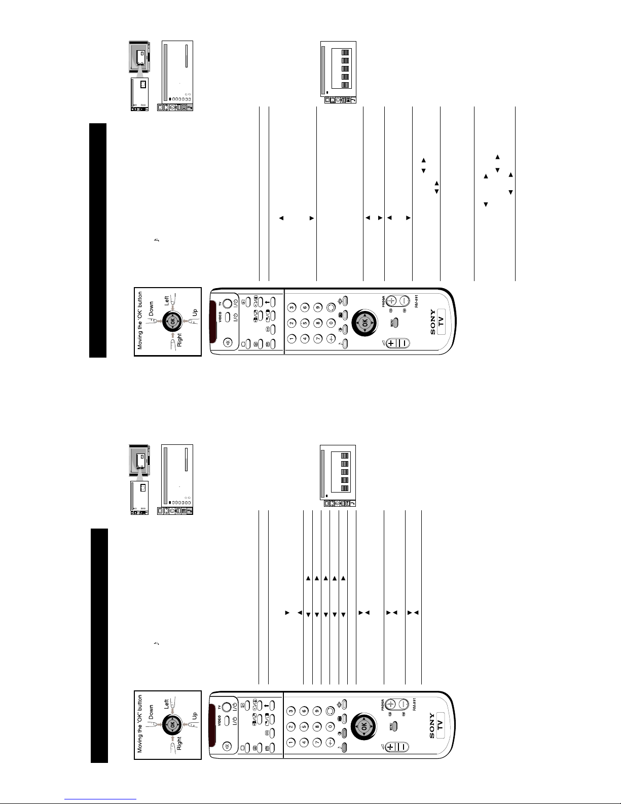
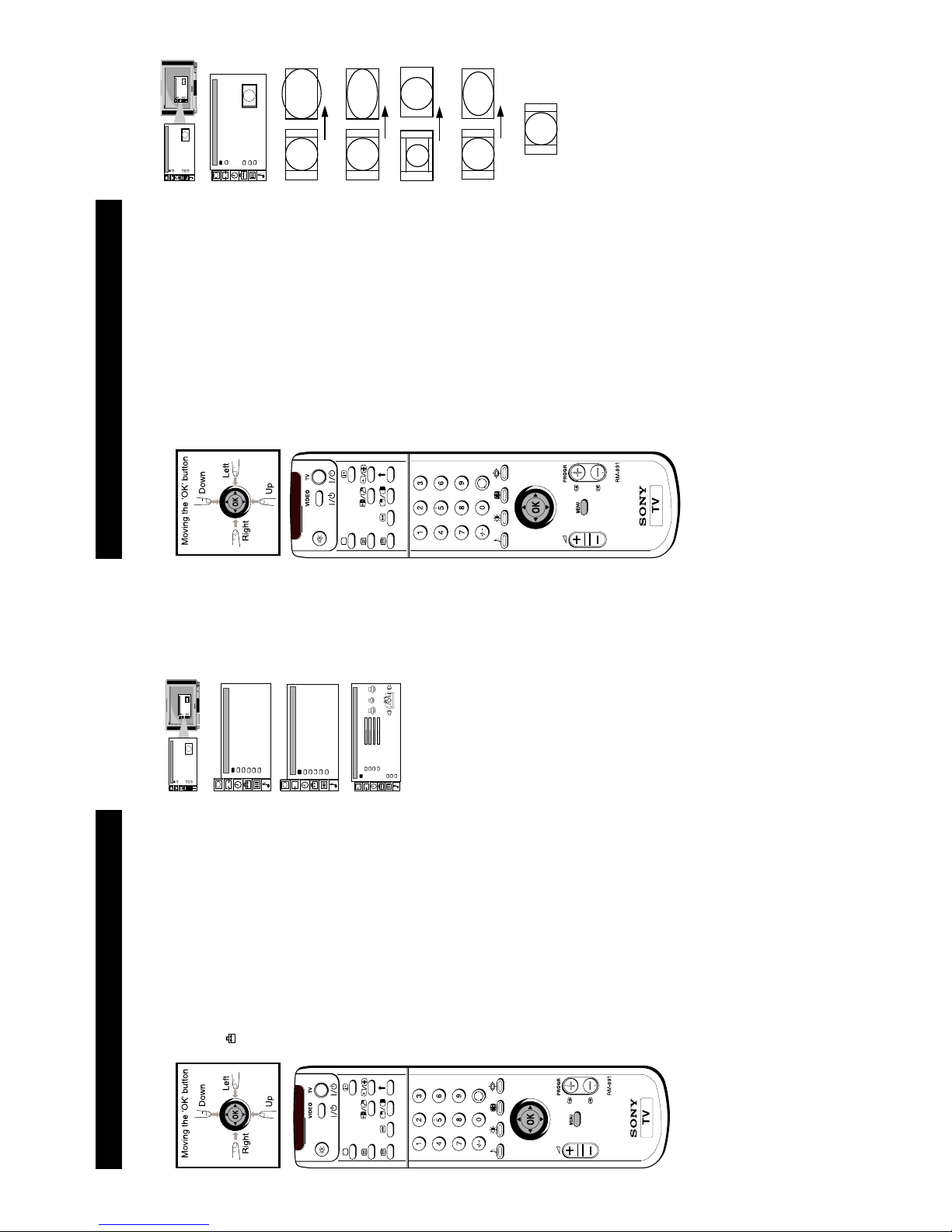
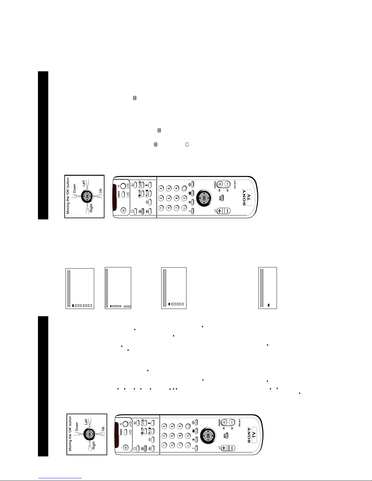
Operating Screen Mode
Additional TV Features
1 Press the MENU button on the remote control to display
the menu on the TV screen.
2 Move the OK button on the remote control RIGHT to
select `Screen Mode', then move to RIGHT to select the
brackets. Move the OK button repeatedly UP or DOWN
to select one of the following modes:
• smart - imitation of wide screen effect (16:9) for 4:3
broadcasts.
• wide - for 16:9 broadcasts
• zoom - imitation of wide screen effect (16:9) for
movies broadcast in cinemascopic format.
In zoom mode and 14:9 mode the top and bottom of
the picture are cut off. Using `Screen position' you
can move the screen up- or downwards in order to
see thecut-off parts (e.g. to read subtitles). Move the
OK button DOWN to select `Screen Position' then
move to RIGHT to confirm. Move the OK button UP
or DOWN to adjust the screen position (-4 to +4).
Press the OK button to confirm.
• 14: 9 - compromise between 4:3 and 16:9 format
• 4:3 - conventional 4 :3 picture
3 Press the OK button to confirm the selection.
4 Strobe Mode
Move the OK button DOWN to select `Strobe'. Press the
OK button to confirm. The TV picture is now displayed
image by image, creating a slow motion effect. Move the
OK button UP or DOWN to select the speed of the
motion. Press the OK button to cancel the strobe mode.
5 Auto 16:9
Move the OK button DOWN to select `Auto 16:9' then
move RIGHT to confirm.
Move the OK button DOWN to select `On' for automatic
selection of format or `Off' for normal mode. Press OK
button to confirm.
6 Correction (only for Auto 16:9)
In case of automatic format detection there are two
possibilities for 4:3/14:9 signals: Set Correction to `on' if
you wish Smart mode to appear on the screen or set it to
`off' if you prefer 4:3/14:9 mode. Move the OK button
DOWN to select `Correction' then move RIGHT to
confirm. Move the OK button DOWN to select `On' or
`Off'. Press OK button to confirm.
7 Press the MENU button to remove the menu from the TV
screen.
Using this Screen Mode feature you can change the aspect ratio of the screen or reproduce the
main picture image by image (Strobe function).
Screen Position
SCREEN MODE
Screen Mode
[zoom ]
[ 0 ]
Strobe
Auto 16:9
Correction
[on]
[off]
Screen Position
SCREEN MODE
Screen Mode
[zoom ]
[ 0 ]
Strobe
Auto 16:9
Correction
[on]
[off]
Screen Position
SCREEN MODE
Screen Mode
[zoom ]
[ 0 ]
Strobe
Auto 16:9
Correction
[on]
[off]
Smart
Wide
Zoom
14:9
4:3
13
17
Sorting Programme Positions
Additional TV Features
After tuning you may wish to change the order in which the channels appear on the TV. You
may wish for example to move the channel on programme number 8 to a different programme
number.
1 Press the MENU button on the remote control to display
the menu on the TV screen.
2 Move the OK button on the remote control DOWN to
select the symbol
on the menu screen then move
RIGHT to enter.
3 Move the OK button DOWN to select `Programme
Sorting' then move RIGHT to confirm.
4 Move the OK button UP or DOWN to select the
programme position of the channel you want to move eg
PROG 8). Press the OK button to confirm.
5 Move the OK button UP or DOWN to select the new
programme position for your selected channel. Press the
OK button to confirm. Your selected channel has now
moved to its new programme number.
6 Repeat steps 4 and 5 to sort other programme positions.
7 Press the MENU button to remove the menu from the TV
screen.
Screen Position
SCREEN MODE
Screen Mode
[zoom ]
[ 0 ]
Strobe
Auto 16:9
Correction
[on]
[off]
Screen Position
SCREEN MODE
Screen Mode
[zoom ]
[ 0 ]
Strobe
Auto 16:9
Correction
[on]
[off]
PRESET
Auto Programme
Programme Setup
Manual Programme Preset
Programme Sorting
Parental Lock
Installation
PROGRAMME SORTING
PROG CH SERVICE
S04
S06
S05
S01
6789101112
C33
C41
C44
C22
C29
C54
C58
S01
S02
S03
Move PR8 to PR- -
PROGRAMME SORTING
PROG CH SERVICE
S05
S06
S03
S01
6789101112
C33
C41
C22
C29
C44
C54
C58
S01
S02
S04
Move PR8 to PR- -
18
Using Parental Lock
This function enables you to prevent children watching undesirable broadcasts.
1 Press the MENU button on the remote control to display
the menu on the TV screen.
2 Move the OK button on the remote control DOWN to
select the symbol
on the menu screen then move
RIGHT to confirm.
3 Move the OK button DOWN to select `Parental Lock' then
move RIGHT to confirm.
4 Move the OK button DOWN to select the channel you
want to block. Press the OK button to confirm. The symbol
appears before the programme position to indicate
that this channel is now blocked. To unblock the channel,
press the OK button again. The symbol
disappears.
5 Repeat step 4 to block other channels.
6 Press the MENU button to remove the menu from the TV
screen.
Screen Position
SCREEN MODE
Screen Mode
[zoom ]
[ 0 ]
Strobe
Auto 16:9
Correction
[on]
[off]
Screen Position
SCREEN MODE
Screen Mode
[zoom ]
[ 0 ]
Strobe
Auto 16:9
Correction
[on]
[off]
PRESET
Auto Programme
Programme Setup
Manual Programme Preset
Programme Sorting
Parental Lock
Installation
PARENTAL LOCK
PROG CH SERVICE
S04
S06
S02
S03
S05
S01
123 4567
C44
C51
C41
C47
C29
C54
C58
S01
Additional TV Features

14
19
Additional TV Features
Using Further Programme Preset
1 Press the MENU button on the remote control to display
the menu on the TV screen.
2 Move the OK button on the remote control DOWN to
select the symbol
on the menu screen then move
RIGHT to confirm.
3 Move the OK button DOWN to select `Installation' then
move RIGHT to confirm.
4 Move the OK button DOWN to select `Further Prog.
Preset' then move RIGHT to confirm.
5 Move the OK button UP or DOWN to select the
programme position you want then move repeatedly
RIGHT to select:
a) VOL (Volume Offset), b) DECODER. The selected item
changes colour.
6a) VOL
Move the OK button UP or DOWN to adjust the volume
for the selected programme position within a range of -7
to +7. Press the OK button to confirm. Repeat steps 5 and 6
to set the volume level for other programme positions.
6b) DECODER
Move the OK button repeatedly DOWN to select AV1 or
AV2 for the programme position and press the OK button
to confirm. Repeat steps 5 and 6 to preset the AV output
for other programme positions.
7 Press the MENU button to remove the menu from the TV
screen.
With this feature you can
a) individually adjust and store the volume level of each channel (Volume Offset).
b) preset the AV output for the programme positions of channels with scrambled signals (e.g.
from a Pay TV decoder). In this way a connected VCR records the unscrambled signal.
Screen Position
SCREEN MODE
Screen Mode
[zoom ]
[ 0 ]
Strobe
Auto 16:9
Correction
[on]
[off]
Screen Position
SCREEN MODE
Screen Mode
[zoom ]
[ 0 ]
Strobe
Auto 16:9
Correction
[on]
[off]
PRESET
Auto Programme
Programme Setup
Manual Programme Preset
Programme Sorting
Parental Lock
Installation
AV Preset
RGB setup
Dolby ProLogic Setup
Picture Rotation
Digital Subtitles
INSTALLATION
Further Prog. Preset
FURTHER PROGRAMME PRESET
PROG VOL DECODER
0
-1
0
-3
0
0
0
1234567
off
AV2
off
off
off
off
off
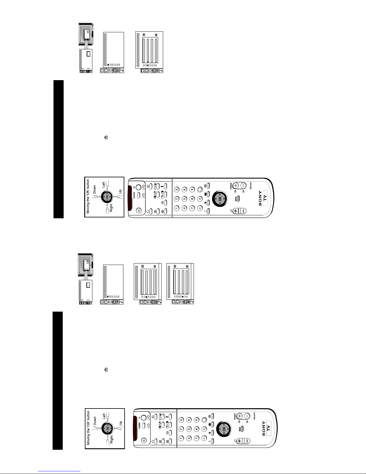
20
Adjusting the Picture Rotation
If, due to the earth's magnetic field, the picture slants, you can use this function to readjust the
picture.
1 Press the MENU button on the remote control to display
the menu on the TV screen.
2 Move the OK button on the remote control DOWN to
select the symbol
on the menu screen then move to
RIGHT to enter.
3 Move the OK button DOWN to select `Installation' then
move RIGHT to enter.
4 Move the OK button DOWN to select `Picture Rotation'
then move RIGHT to enter.
5 Move the OK button RIGHT then move UP or DOWN to
adjust the picture rotation. The adjusting range is - 4 to +4.
Press the OK button to enter.
6 Press the MENU button to remove the menu from the TV
screen.
Additional TV Features
Screen Position
SCREEN MODE
Screen Mode
[zoom ]
[ 0 ]
Strobe
Auto 16:9
Correction
[on]
[off]
Screen Position
SCREEN MODE
Screen Mode
[zoom ]
[ 0 ]
Strobe
Auto 16:9
Correction
[on]
[off]
PRESET
Auto Programme
Programme Setup
Manual Programme Preset
Programme Sorting
Parental Lock
Installation
AV Preset
RGB setup
Dolby ProLogic Setup
Picture Rotation
Digital Subtitles
INSTALLATION
Further Prog. Preset
PICTURE ROTATION
Rotation
[+ 3 ]
15
21
Additional TV Features
Displaying Subtitles
1 Press the MENU button on the remote control to display
the menu on the TV screen.
2 Move the OK button on the remote control DOWN to
select the symbol
on the menu screen then move
RIGHT to enter.
3 Move the OK button DOWN to select `Installation' then
move RIGHT to enter.
4 Move the OK button DOWN to select `Digital Subtitles'
then move RIGHT to enter.
5 Move the OK button RIGHT to select `Digital Subtitles'
then move DOWN to switch on/off digital subtitles.
6 Press the OK button to enter.
7 If you have switched on the subtitles and wish to change
the subtitle language, move the OK button DOWN to
select `Subtitle Language' then move RIGHT to highlight
the language options.
8 Move the OK button repeatedly DOWN to select your
chosen language then press the OK button to confirm your
choice.
9 Press the MENU button to remove the menu from the TV
screen.
With this feature you can view subtitles on the TV screen when watching digital channels.
When watching analogue channels you can view subtitles via the teletext menu screen (see the
Teletext section of this instruction manual).
Screen Position
SCREEN MODE
Screen Mode
[zoom ]
[ 0 ]
Strobe
Auto 16:9
Correction
[on]
[off]
Screen Position
SCREEN MODE
Screen Mode
[zoom ]
[ 0 ]
Strobe
Auto 16:9
Correction
[on]
[off]
PRESET
Auto Programme
Programme Setup
Manual Programme Preset
Programme Sorting
Parental Lock
Installation
AV Preset
RGB setup
Dolby ProLogic Setup
Picture Rotation
Digital Subtitles
INSTALLATION
Further Prog. Preset
DIGITAL SUBTITLES
Digital Subtitles [ on ]
Subtitle Language [English ]
22
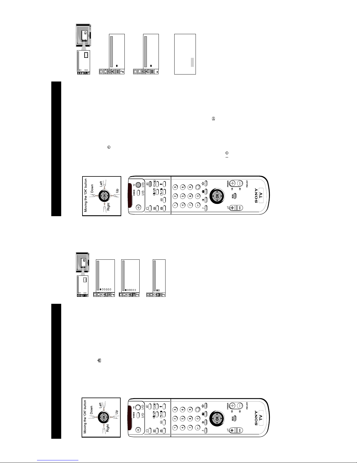
Additional TV Features
Using the Sleep Timer
The TV can be set to switch automatically to standby mode after a length of time chosen by you.
You may set the time in 15 minute steps up to 4 hours.
1 Press the MENU button on the remote control to display
the menu on the TV screen.
2 Move the OK button on the remote control DOWN to
select the
symbol on the TV screen, then move RIGHT
twice.
3 Move the OK button UP or DOWN repeatedly until the
required amount of time delay appears on the screen.
4 Once the time delay has been selected, press the OK
button to enter.
5 Press the MENU button to remove the menu from the TV
screen.
One minute before standby, the display shown appears
on the screen.
Notes:
• When watching TV, press the
button to display time
remaining.
• To return to normal operation from standby mode, press
the
/
button.
Screen Position
SCREEN MODE
Screen Mode
[zoom ]
[ 0 ]
Strobe
Auto 16:9
Correction
[on]
[off]
Screen Position
SCREEN MODE
Screen Mode
[zoom ]
[ 0 ]
Strobe
Auto 16:9
Correction
[on]
[off]
TIMER
Sleep Timer
[off ]
TIMER
Sleep Timer
[2:30 ]
:59
16
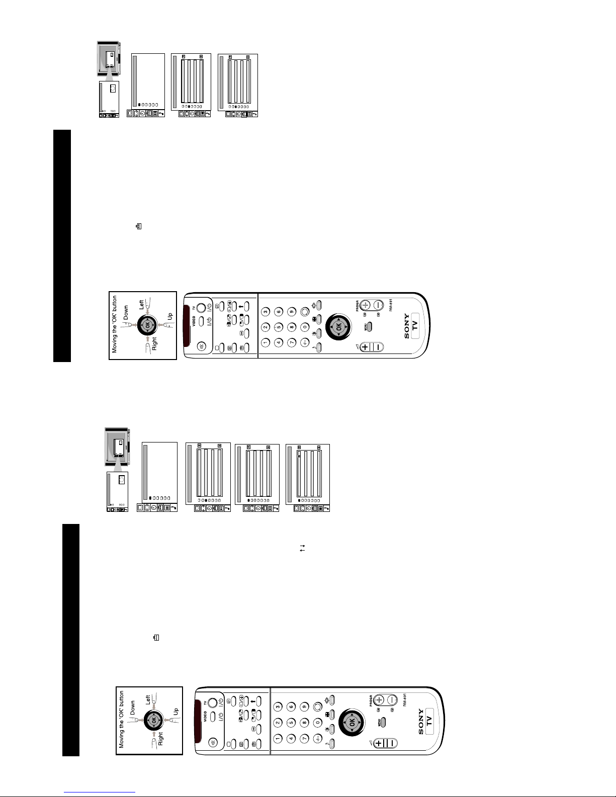
23
Manually Tuning the TV
1 Press the MENU button on the remote control to display
the menu on the TV screen.
2 Move the OK button on the remote control DOWN to
select the
symbol on the menu screen then move
RIGHT to enter.
3 Move the OK button DOWN to select `Manual
Programme Preset' then move RIGHT to enter.
4 Move the OK button UP or DOWN to select a
programme number for your channel
(eg PROGR 1 for
BBC1) then move RIGHT to enter.
5 Move the OK button repeatedly RIGHT until
appears
in the SEARCH column.
6 Move the OK button UP or DOWN to search for a
channel.
7 If you do not wish to store this channel on the
programme number you selected, move the OK button
UP or DOWN to continue searching for the desired
channel.
8 If this is the channel you wish to store, press the OK
button.
9 Repeat steps 4 to 8 if you wish to store more channels
then press the MENU
button to remove the menu from
the TV screen.
Additional TV Features
You have already tuned the TV to receive all available channels using the `Automatically
Tuning the TV' procedure at the start of this manual. You can however carry out this
operation manually using the following instructions.
Screen Position
SCREEN MODE
Screen Mode
[zoom ]
[ 0 ]
Strobe
Auto 16:9
Correction
[on]
[off]
Screen Position
SCREEN MODE
Screen Mode
[zoom ]
[ 0 ]
Strobe
Auto 16:9
Correction
[on]
[off]
PRESET
Auto Programme
Programme Setup
Manual Programme Preset
Programme Sorting
Parental Lock
Installation
MANUAL PROGRAMME PRESET
PROG INPUT CH SERVICE SEARCH
TV
TV
TV
TV
TV
TV
TV
1234567
S01
S02
S03
S04
S05
S06
S01
off
off
off
off
off
off
off
C34
C34
C34
C34
C34
C34
C38
MANUAL PROGRAMME PRESET
PROG INPUT CH SERVICE SEARCH
TV
TV
TV
TV
TV
TV
TV
1234567
S01
S02
S03
S04
S05
S06
S01
off
off
off
off
off
off
off
C34
C34
C34
C34
C34
C34
C38
MANUAL PROGRAMME PRESET
PROG INPUT CH SERVICE SEARCH
TV
TV
TV
TV
TV
TV
TV
1234567
S01
S02
S03
S04
S05
S06
S01
off
off
off
off
off
off
C34
C34
C34
C34
C34
C34
C38
24
Skipping Programme Positions
This function enables you to skip unused programme positions when selecting them with the
PROGR +/- buttons. However, by using the number buttons you can still select the skipped
programme position.
1 Press the MENU button on the remote control to display
the menu on the TV screen.
2 Move the OK button on the remote control DOWN to
select the symbol
on the menu screen then move
RIGHT to enter.
3 Move the OK button DOWN to select `Manual
Programme Preset' then move RIGHT to enter.
4 Move the OK button UP or DOWN to select the
programme position you want to skip then move RIGHT
to enter.
5 Move the OK button DOWN to select `---' in the position
INPUT. Press the OK button to enter.
6 Repeat steps 4 and 5 to skip other programme positions.
7 Press the MENU button to remove the menu from the TV
screen.
Screen Position
SCREEN MODE
Screen Mode
[zoom ]
[ 0 ]
Strobe
Auto 16:9
Correction
[on]
[off]
Screen Position
SCREEN MODE
Screen Mode
[zoom ]
[ 0 ]
Strobe
Auto 16:9
Correction
[on]
[off]
PRESET
Auto Programme
Programme Setup
Manual Programme Preset
Programme Sorting
Parental Lock
Installation
MANUAL PROGRAMME PRESET
PROG INPUT CH SERVICE SEARCH
TV
TV
TV
TV
TV
TV
TV
1234567
S01
S02
S03
S04
S05
S06
S01
off
off
off
off
off
off
off
C34
C34
C34
C34
C34
C34
C38
MANUAL PROGRAMME PRESET
PROG INPUT CH SERVICE SEARCH
TV
TV
TV
---
TV
TV
TV
1234567
S01
S02
S03
S04
S05
S06
S01
off
off
off
off
off
off
off
C34
C34
C34
C34
C34
C34
C38
17
25
Adjusting the TV Picture for an RGB Source
After connecting an RGB source such as a playstation to the TV, you may need to adjust your
TV picture.
1 Press the * button repeatedly on your remote control to
display the * symbol on the TV screen.
2 Press the MENU button on your remote control to display
the menu on the TV screen.
3 Move the OK button DOWN to select the symbol
on
the menu screen then move RIGHT to enter the `PRESET'
m,enu.
4 Move the OK button DOWN to select `Installation' on the
TV screen then move RIGHT to enter the
`INSTALLATION' menu.
5 Move the OK button DOWN to select `RGB SetUp' on the
TV screen then move RIGHT to enter the `RGB SETUP'
menu.
6 Move the OK button RIGHT to select `H Centre' on the
screen then move UP or DOWN to adjust the centre of the
picture over a range of -20 to +20.
7 Press the OK button to confirm the range.
8 Move the OK button DOWN to select `H Size' then move
RIGHT to highlight the range.
9 Move the OK button UP or DOWN to adjust the
horizontal slant of the picture over a range of -20 to +20.
10Press the OK button to confirm the new range.
11PPress the MENU button to remove the menu from the TV
screen.
Screen Position
SCREEN MODE
Screen Mode
[zoom ]
[ 0 ]
Strobe
Auto 16:9
Correction
[on]
[off]
Screen Position
SCREEN MODE
Screen Mode
[zoom ]
[ 0 ]
Strobe
Auto 16:9
Correction
[on]
[off]
RGB SETUP
Reset
Centre
Size
Mode: RGB
x: 0 y: 0
+
RGB SETUP
Reset
Centre
Size
Mode: RGB
x: 0 y: 0
+
26
Viewing Standard Teletext
Teletext
Index
TELETEXT
Programme
News
Sport
Weather
25
153
101
98
Index
TELETEXT
Programme
News
Sport
Weather
25
153
101
98
Standard Teletext is an information service transmitted by broadcasters which can be viewed
on most of your traditional analogue channels.
Index
TELETEXT
Programme
News
Sport
Weather
25
153
101
98
Index
TELETEXT
Programme
News
Sport
Weather
25
153
101
98
Selecting Teletext
1 When viewing analogue channels, press a number button
on the remote control to select the channel which carries
the teletext service you wish to receive.
2 Press the
button on the remote control to switch on
teletext. Press the
button again to superimpose
teletext on to the TV screen.
3 Input three digits for the page number using the
numbered buttons on the control. If you make a mistake,
type in any three digits then re-enter the correct page
number.
Using Other Teletext Functions
Page Catching
Input a teletext page number. Press the OK button. `Page
Catching' is displayed at the top of the page. Move the OK
button UP or DOWN to select the page number you require.
Press the OK button. The requested page is displayed after
some seconds.
To Move to Next or Preceding Page
Press
or
on the control to select the previous or next
page.
To Freeze a Teletext Page
Press
on the control to freeze the page. Press
again to
cancel the freeze.
Revealing concealed information (eg: answers to a
quiz).
Press
to reveal information. Press again to conceal the
information.
Using colour buttons to access pages
When the colour coded menu appears at the bottom of a
page, press the colour button (green, red, yellow or blue)
on
the control to access the corresponding page.
18
27
Viewing Standard Teletext
Select further standard teletext functions as follows:
Using the Teletext Menu
1 With teletext on the TV screen, press the MENU button
on the remote control to display the teletext menu.
2 Move the OK button on the remote control DOWN to
select the teletext function you want then move RIGHT
to confirm your choice.
Preset User Pages...
For quick access to the pages you frequently use, you can
store your favourite teletext pages.
1 Push to to select the bank (from A to E) in which you
want to store the pages then push to to confirm.
2 Push to to select the three digits of your 6 favourite
pages in columns P1 -P6. Push to after selecting each
digit. Press the OK button to confirm your selections.
3 Push to to select `Allocate Bank' then push to to
confirm.
4 Push to to select the programme position which is
carrying the teletext service containing your favourite
pages, then push to to confirm.
5 Push to to select the bank chosen in step 1 then press
the OK button to confirm.
6 Repeat steps 1 to 5 if you wish to store pages in the other
four available banks.
User Pages...
7 Push to twice to display the Teletext menu screen.
8 Push to to select User Pages then push to to confirm.
9 Push to to select a favourite page then press the
OK button to display the page.
Index
The index gives you an overview of the teletext contents.
Top/Bottom/Full
For easier reading, you can enlarge the teletext page. Push
the OK button to to enlarge the upper half, push to to
enlarge the lower half. Press the OK button to resume the
normal display.
Text Clear
After selecting this function, you can watch a TV programme
while waiting for a requested teletext page to be captured.
When the page is available, it will be displayed.
Subtitles
Check with your teletext service for information about
subtitled TV programmes. After selecting the function the
subtitles are displayed. Press the function again to remove
the subtitles.
Time Page
Check with your teletext service about the availability of
time coded pages. If available, you can call up a page at a
certain time.
1 With the Time Page menu on the TV screen, push to
then push to to select `on'. Push to to confirm.
2 Push to to enter the three digits of the page you want
(eg 301) and the four digits of the desired time (eg 18:54).
Push to after each digit. Press the OK button to
confirm. At the requested time, the page you selected is
displayed.
Subpage
Using this function you can select the subpages, if available,
of a particular teletext page. After selecting the function
push to to access the various subpages. Select the
function again to cancel the request.
TELETEXT MENU
User Pages ...
Index
Top/Bottom/Full
Text Clear
Subtitles
Time Page
Sub Page ...
Preset User Pages ...
PRESET USER PAGES
BANK P1 P2 P3 P4 P5 P6
ABCDE
Allocate Bank
Prog Label Bank Prog Label Bank
232
151
- - -
- - -
- - -
102
100
- - -
- - -
120
123
4
BBC1
BBC2
ITV
CH4
AB-
-
5 6 7
8
S4C
- - - - -
- - - - -
- - - - -
A - -
-
154
252
- - -
- - -
- - -
- - -
- - -
- - -
- - -
- - -
- - -
380
- - -
- - -
- - -
160
- - -
- - -
- - -
- - -
USER PAGES BANK A
Page 102
Page 200
Page 354
Page 100
Page 380
Page 124
TIME PAGE
off - - - - - : - -
Teletext
28
Selecting Teletext
1 To view the digital teletext service, firstly select the
dedicated teletext channel.
2 Individual Teletext pages are then selected by using the
UP, DOWN, LEFT or RIGHT buttons to guide the on-
screen cursor to the required area of the screen. Pressing
the OK button then displays the chosen information.
3 Alternatively, use the numeric buttons 0-9 to directly
enter the number of the page you require.
4 When you have finished viewing Teletext, select an
alternative channel in the normal manner.
Normal Teletext services may also be available on other
digital channels and are selected using the
button.
1 Press a number button on the remote control to select the
channel which carries the teletext service you wish to
receive.
2 Press the
button on the remote control to switch on
teletext. Press the
button again to superimpose
teletext on to the TV screen.
3 Input three digits for the page number using the
numbered buttons on the control. If you make a mistake,
type in any three digits then reenter the correct page
number.
4 Press the
button to switch off teletext.
Viewing Digital Teletext
Most of the digital TV channels broadcast information via teletext.
Teletext
19
29
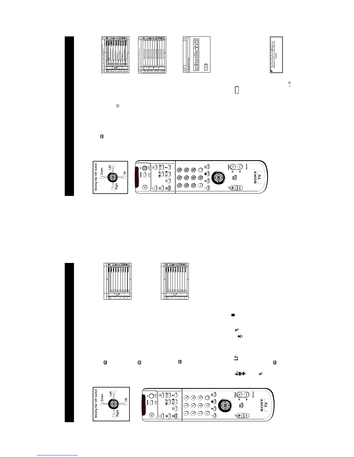
Electronic Programme Guide (EPG)
The Electronic Programme Guide (EPG) is a guide which provides programme information
for all digital channels supporting EPG.
Electronic Programme Guide
Tue 22 DEC
15:20:40
22
Tues
23
Wed
24
Thu
25
Fri
26
Sat
27
Sun
28
Mon
6912
15
18
21243
12
2
BBC 2
International Cricket - - - -
13:35 - 18:25
- 1h NOW 1h 2h
4
5
1
3
1
1
3
4
Channel 4
C 5
BBC 1
HTV
BBC 1
HTV
BBC 1
Racing From Epsom - - -
14:00 - 16:30
Film: Rachel And The - - -
15:30 - 17:10
The Little Pet Shop - - -
15:50 - 16:00
Bernards Watch
15:55 - 16:15
Boger And Badger N
16:00 - 16:15
Bailey Kippers Pov S - - -
16:15 - 16:35
Sabrina The Teenage - -
- 16:15 - 16:40
Vets In Practice
16:30 - 17:30
Press O.K. to view data for all available channels
Press to return to programme list.
12
16:00
ALL
BBC 1
Displaying the EPG
1 Press the button on the remote control to display the
programme guide on the TV screen. You may see the
message ’EPC INFORMATION IS TEMPORARILY
UNAVAILABLE’ whilst waiting for the EPG to appear on
screen.
2 Move the OK button on the remote control UP, DOWN,
LEFT or RIGHT to move the on-screen cursor around the
guide.
3 Press the
button again to remove the programme
guide from the TV screen.
Viewing Information on the EPG
You can alter the type of information presented on the EPG
by changing data in each of the EPG columns. You can for
example display information for all sports programmes
being shown tomorrow from 5.00pm onwards.
1 Press the
button on the remote control to display the
EPG on the TV screen.
2 Move the OK button on the remote control RIGHT or
LEFT to highlight the ‘date’ column then move the OK
button UP or DOW’N to select your chosen date.
3 Move the OK button RIGHT or LEFT to highlight the
‘time’ column then move the OK button UP or DOWN to
select your chosen time.
4 Move the OK button RIGHT or press the OK button. The
EPG will display programme information according to
the date and time you selected.
5 Move the OK button RIGHT to highlight the ‘progamme
type’ column then move UP or DOWN to select
Films,
News, Lifestyle, Sport,
Children’s Programmes, Entertainment or
Education.
6 Move the OK button RIGHT or LEFT or press the OK
button to update the programme information
accordingly. If you selected tomorrow’s date, 17:00 and
Sport, you should now be able to view all the sports
programmes being shown tomorrow from 5.00 pm
onwards.
7 Press the
button on the remote control to remove the
EPC from the TV screen.
31
Electronic Programme Guide (EPG)
Electronic Programme Guide
Setting The Manual Timer
1 Press the button on the remote control to display the
EPG on the TV screen.
2 Move the OK button RIGHT or LEFT to highlight the
‘programme type ’ column then move the OK button
DOWN to select the timer symbol
.
3 Press the OK button to display a screen of 9 programme
slots, each one indicating that it is either free for
programming, or that it has a programme already stored in
it.
4 Move the OK button LEFT to enter the ‘programme’
column.
5 Move the OK button UP or DOWN to select a free row
then press the OK button to display the Set Timer screen.
This screen asks you to confirm the date, programme
number, start time and stop time.
6 Move the OK button UP to select the date area then move
the OK buttons UP or DOWN to enter the date.
7 Move the OK button RIGHT to confirm the date then press
the OK button UP or DOWN to select the month.
8 Move the OK button RIGHT to confirm the month and to
select the start time.
9 Move the OK button UP or DOWN to enter the time you
wish the timer to switch on, preferably several minutes
before your video recorder is due to start recording.
Move the OK button RIGHT to confirm after each entry.
10 Move the OK button UP or DOWN to enter the time you
want the timer to switch off, preferably after your video is
due to stop recording.
11 Move the OK button RIGHT to confirm each entry, then
move the OK button UP or DOWN to select the
programme number.
12 Press the OK button to save the settings, then follow the
on-screen instructions until you finally select
Return
to
return to the Manual Timer Setup menu.
13 Select another available slot if you wish to record a further
programme. Otherwise, move the OK button RIGHT to
enter the ‘programme type’ column then press the OK
button to return to the EPG.
14 If you have finished viewing programmes on your TV,
press the button before the timer recording starts. This will
leave your TV in standby mode for the timer settings to be
activated. If, however, you wish to continue
watching other programmes after setting the timer, you
can do so by changing programmes in the normal way. If
you are watching another programme when the timer is
due to start, the display shown will appear on screen.
15 If you do not wish to view the recording, press the
/
button whilst the display is still on screen to leave your TV
in standby mode. The standby indicator on the front of the
TV will flash to show that the timer record operation is
active. If, however, you choose to change programmes,
you will automatically cancel the recording.

20
36
Troubleshooting
Additional Information
Problem Cause
No picture, no sound. • Power off.
• TV in standby.
• Aerial disconnected.
Poor or no picture (screen is dark), but good sound. • Picture preset level adjustment.
No picture on any channel after digital tuning. • No digital transmissions in your area.
• No digital transmissions from the transmitter you are
currently using.
• Weak signal.
• Unsuitable aerial.
Some channels are blank. • Scrambled/subscription-only channel.
• Programme used only for data (no picture or sound).
• Programme not being transmitted.
Standby indicator flashing. • Digital mode Timer Record active (regular flash).
• Fault (irregular flash).
Good picture, no sound. • Volume control.
Poor picture quality. • Wrong external mode selected on an RGB video source.
No colour on colour programmes. • Colour level setting.
Remote contol does not function. • Batteries low.
Distorted picture when changing programmes or • Inputs from external equipment not switched off.
selecting Teletext.
Cause Solution
Power off. • Plug in the TV.
TV in Standby. • Press the
button on the front of the TV.
• If the
indicator is on, press the
/
button or a
programme number on the remote control.
Aerial disconnected. • Check the aerial connection.
Picture level adjustment. • Select
on the TV menu system then adjust the
brightness, picture and colour balance levels.
• Lift the flap of the remote control and
press
to
return to the preset factory levels.
No digital transmissions in your area. • Switch the TV to analogue mode using the
‘Automatically tuning the TV’ section of this instruction
manual then contact a local installer to find out when
digital transmissions start in your area.
No digital transmissions from the • Contact a local installer to find out which
transmitter you are currently using transmitter you should be pointing your aerial at.
Unsuitable aerial. • Change your aerial to cover the channels used by digital
programmes (Contact a local installer).
Weak signal. • Ensure aerial is plugged directly into the TV (not
through other equipment).
• Ensure aerial is correctly aligned to transmitter.
• Upgrade to a higher gain aerial.
Scrambled/subscription-only channel. • Subscribe to pay-per-view broadcaster.
Programme information without picture or sound. • See “Skipping programme position” section.
• See “Exchanging programme positions” section.
Fault. • Do not open the cabinet, refer to qualified person.
• Contact your nearest Sony Service Centre.
Volume control. • Press the
+ button on the remote control.
• If
is displayed on the screen, press the button on
the remote control.
Wrong external mode selected. • Press the
button repeatedly on the remote control
until the RGB symbol
is displayed on screen.
Colour level setting. • Select
in the TV menu system then adjust the colour
setting.
• Lift the flap of the remote control and
press
to
return to the preset factory level.
• If you continue to have these problems, have your TV serviced by qualified personnel.
• Never open the casing yourself.
35
Additional Information
Specifications
TV systemIColour system
PAL
NTSC 3.58, 4.43 (only Video In)
Channel coverage
UHF:B21-B69
Picture tube
KV-28DS60U/28DS65U
FD Trinitron WIDE
Approx. 71 cm (28 inches) (Approx. 66 cm picture measured diagonally),
102° deflection
KV-32DS60U/32DS65U
FD Trinitron WIDE
Approx. 82 cm (32 inches) (Approx. 76 cm picture measured diagonally),
102° deflection
Rear Terminals
1
/
1
21-pin Euro connector (CENELEC standard) including audio/video
input, RGB input, TV audio/video output
2
/
s
2
21-pin Euro connector (CENELEC standard) including audio/video
input, S-video input, Monitor audio/video output
4
/
s
4
21-pin Euro connector (CENELEC standard) including audio/video
input, S-video input, Monitor audio/video output
Audio outputs - phono jacks
MODEM Modem Connector
Front Terminals
3
video input - phono jack
3
audio inputs - phono jacks
s
3
S video input - 4 pin DIN
Headphones jack - minijack stereo
Sound output:
Left/Right 2 x 30 W (music power) 2 x 15W (RMS)
Centre 1x30W (music power) 1x15W (RMS)
Surround 2x15W (music power) 2x 7.5 (RMS)
Power consumption
KV-28DS60U/28DS65U 200 W
KV-32DS60U/32DS65U 200 W
Dimensions (wxhxd)
KV-28DS60U/28DS65U Approx. 773 x 501 x 526 mm
KV-32DS60U/32DS65U Approx. 867 x 564 x 558 mm
Weight
KV-28DS60U/28DS65U Approx. 53.0 kg
KV-32DS60U/32DS65U Approx. 71.5 kg
Accessories supplied
RM-891 or RM-892 Remote Control (1)
IEC designated size AA battery (2)
Surround speaker (2)
Other features
TELETEXT
DNR (Digital Noise Reduction)
Dolby ProLogic Surround System
Graphic Equalizer
NICAM Stereo
Smartlink
Design and specifications are subject to change without notice.
21
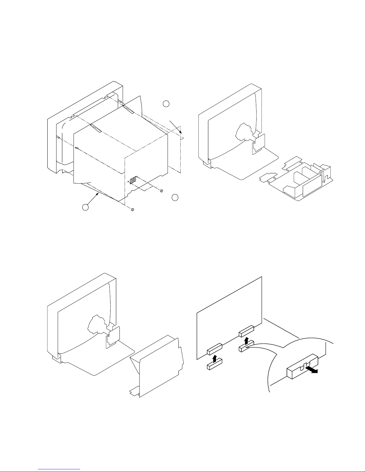
2-1. REAR COVER REMOVAL
2-3. SERVICE POSITION
2-2. CHASSIS ASSY REMOV AL
1
6 Screws
BTV 4x16
2-4. A1 BOARD REMOVAL
SECTION 2
DISASSEMBLY
2
2 Screws
BTV 4x16
3 Rear Cover
22
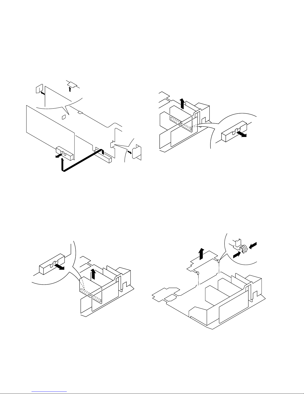
2-5. J BOARD REMOVAL
2-7. D1 BOARD REMOVAL
2-6. B BOARD REMOVAL
2-8. H BRACKET REMOVAL
23
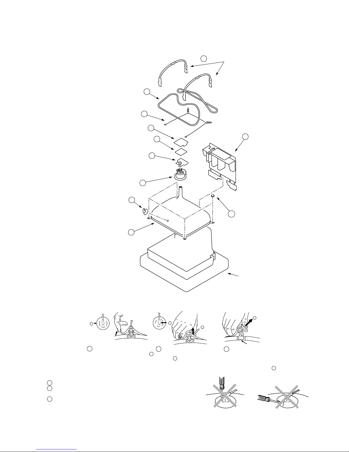
Anode button
a
* REMOVING PROCEDURES.
Turn up one side of the rubber cap in
the direction indicated by the arrow a
1
2 Using a thumb pull up the rubber cap
firmly in the direction indicated by the
arrow b
3 When one side of the rubber cap is
separated from the anode button, the
anode-cap can be removed by turning
up the rubber cap and pulling it up in
the direction of the arrow c
b
b
c
Note : Short circuit the anode of the picture tube and the anode c ap to the metal chassis, CRT shield or carbon paint on the CRT, after removing the anode.
• REMOVAL OF ANODE-CAP
• HOW TO HANDLE THE ANODE-CAP
1 To prevent damaging the surface of the anode-cap do not use sharp mate rials.
2 Do not apply too great a pressure on the rubber, as this may cause damage to
the anode connector.
3 A metal fittin g called a shatter hook terminal is fitted inside the rubber cap.
Do not turn the rubber foot over excessively this may caus e da mage if the
shatter hook sticks out.
Cushion
2-9. PICTURE TUBE REMOVAL
7 DGC holder
Picture tube 11
C board 3
Spring tension 9
Degaussing coils 8
Anode cap 1
Neck assy 5
VM board 4
Deflection yolk 6
2 Chassis assy
10 Four PT screws
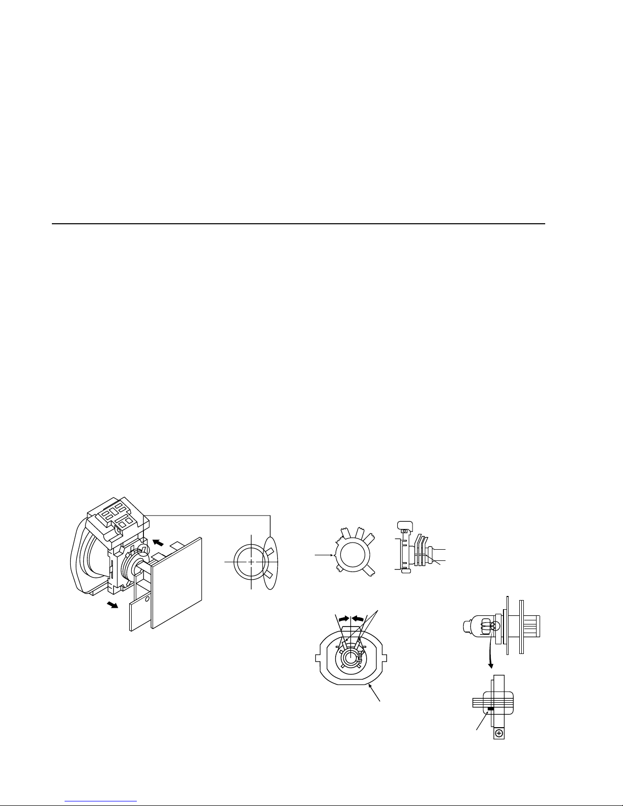
24
• When complete readjustment is necessary or a new
picture tube is inst alled, carry out the following
adjustments.
• Unless there are specific instructio ns to the contrary,
carry out these adjustments with the rated power supply.
• Unless there are specific instructions to the contrary, set the
controls and switches to the following settings:
Contrast ............... normal
Brightness ............... normal
Carry out the following adjustments in this order:
3-1. Beam Land ing
3-2. Convergence
3-3. Focus
3-4. White balance
Note: Test equipment required
1. Color bar/pattern generator.
2. Degausser.
3. Digital multimeter.
4. Oscilloscope.
SECTION 3
SET-UP ADJUSTMENTS
3-1.BEAM LANDING
Preparation:
1. In order to reduce the influence of geomagnetism on the set’s
picture tube, face it in an easterly or westerly di rection.
2. Swi tch on the set’s power and degauss with the
degausser.
(1) Adjustment of Correction Magnet for Y-Splitting
Axis
1. Input a crosshatch signal from the pattern generator.
2. Set t he Picture control to minimum and confirm that the
Brightness control is set to normal.
3. Position the neck assembly as indicated in Fig.3-2.
4. Move the deflection yolk as far forward as is possible.
5. Adjust the upper and lower pin symmetrically by opening or
closing the Y-splitting axis correct ion magn ets located o n the
neck assembly.
6. Return the deflection yolk to its original position.
Caution :
High voltages are present on the Deflection yolk terminals - take
care when handling the Deflection yo lk whilst carrying out
adjustments.
(2) Landing
Note :Before carryin g out the following adjustments
adjust the magnets as indicated below [See Fig.3-3].
1. Input an all-white signal from the pattern generator.
Maximize the picture setting and adjust the Brightness
setting.
2. Ro ugh-adjust the focus and horizontal convergence.
3. L oosen the deflection yolk screws and align the purity
adjustment knob to its central position. [See Fig.3-1].
4. Switch from the all-white pattern to an all-green pattern.
5. M ove the deflection yolk backwar ds and adjust with the
purity magnet so that the green is at the centre and it aligns
symmetrically. [See Fig.3-4].
6. Move the deflection yolk for w ard and adjust so that the
entire screen becomes green.
7. Switch the raster signal to red, then to blue and verify the
landing condition.
8. When the position of the deflection yo lk has been determined, fasten the deflection yolk with the screw.
9. If the beam does not land correctly in all the corners of the
screen, use magnets to correct it. [See Fig.3-5].
Y-splitting axis correctio n magnet
Fig.3-1
Fig.3-2
Purity
Align Pips
on each
magnet
Neck assy
Align the bottom edge
of the neck assy with
the G3 hole centre.
Deflection yoke
Fig.3-3
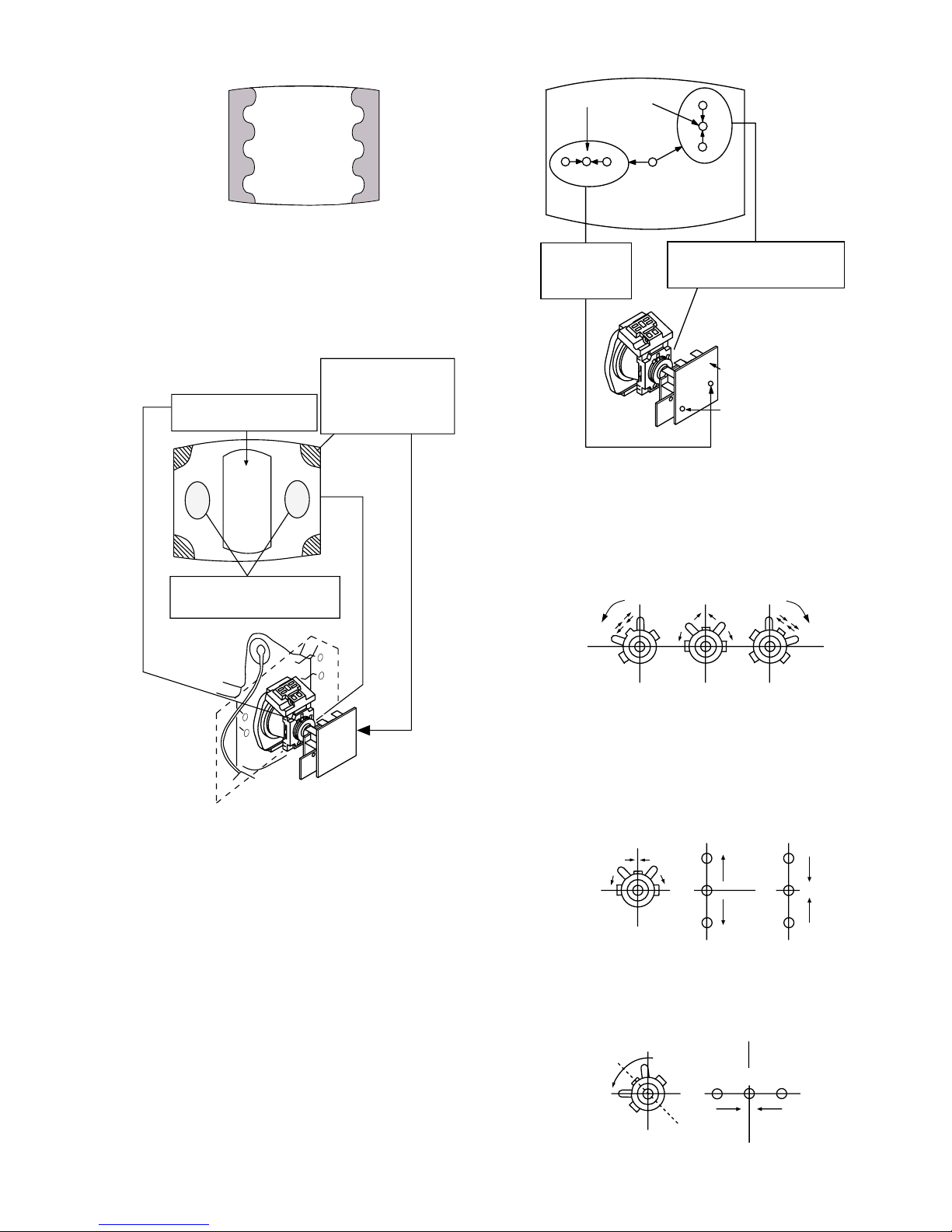
25
Fig.3-4
Fig. 3-5
3-2.CONVERGENCE
(1) Screen centre convergence
[Static convergence]
1. Input a dot signal from the pattern generator.
Normalize the picture setting.
2. [Moving horizontally], adjust the H.STA T c ontrol so th at the
horizontal red, gr een and blue dots coincide at the centre of
the screen.
3. [Moving vertically], adjust the V.STAT magnet so that the
vertical red, green and blue dots coincide at the centre of the
screen.
• If the horizont al dot s are un able to coi nci de with the v ari able
range of the H.STAT convergence, adjust together with the
V.STAT convergence while tracking.
[Adjust the convergence by tilting the V.STAT convergence
or by opening and closing the V.S TAT convergence.]
4. Movement of the red, green and blue dots by tilting the
V.STAT magnet and by opening or closing the V.STAT
magnet.
a). By opening or closing the V.STAT magnet, the red, green
and blue dots move as indicated below.
b). By rotating the V.STAT m agnet counter clockwise, the red,
green and blue dot s move as indicated below.
Purity control corrects
this area.
Disk magnets or
rotatable disk
magnets correct
these areas (a-d).
Deflection yoke positioning
corrects these areas
H.STAT
convergence
control
V.STAT
vertical static magnet
Centre dot
H.STAT VR on
mount side
RV5376
Screen (G2)
H.STAT convergence
(Open)
(Close)
B
G
R
B
G
R
B
GR
GREEN
BLUE
RED
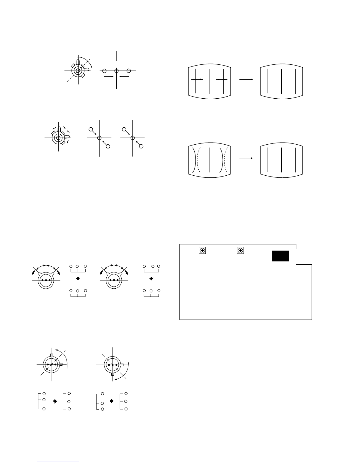
26
B
GR
B
G
R
B
G
R
HMC correction(A) HMC correction(B)
A < B
A = B
RG B
RG B
A > B
A = B
RGB
RG B
C < D
C = D C > D C = D
R
G
B
C
D
C
D
R
G
B
R
G
B
R
G
B
VMC correction(A) VMC correction(B)
D1
H-TILT
CBH
RV1502
RV1503
c). By rotating the V.STA T magnet clockwise, the red, green and
blue dots move in the direction indicated below.
d). By opening or closing the V.STAT magnet, the red, green
and blue dots move in the direction indicated below.
Note : If the blue dot does not coi ncide with the red and
green points correct the points by using the BMC
[Hexapole] magnet.
5. Correction for HMC [horizontal mis-convergence] and
VMC [vertical mis-convergence] by using the BMC
[Hexapole] magnet.
a). HMC correction by BMC [Hexapole] magnet and movement
of the electr o n be a m.
b). VMC correction by BMC [Hexapole] magnet and movement
of the electr o n be a m.
(2) Dynamic convergence
HTIL
1. HTIL correction can be performed by adjusting RV1502 on
the D1 board.
COR.BOW
2. COR.BOW correction can be performed by adjusting
RV1503 on the D1 board.
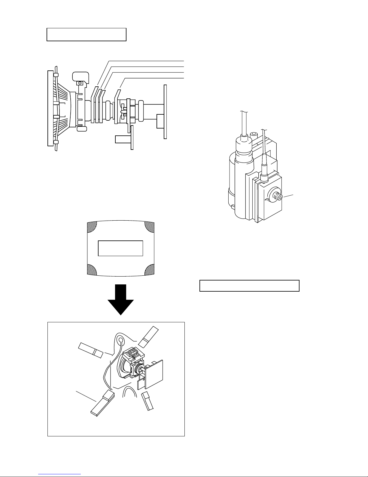
27
FOCUS
Layout of each control
Note : If you are unable to adjust the corner convergence
properly, this can be corrected with the use of
permalloys.
3-3.FOCUS
1. Receive a television broadcast signal.
2. Normalize the picture setting.
3. Ad j ust the focus control located on the flyback transformer
to obtain the best focus at the centre of t he screen.
Bring only the centre area of the screen into focus, the
magenta-ring appears on the scree n. In th is case, adjust the
focus to optimize the screen uniformly.
3-4.SCREEN (G2), WHITE BALANCE
[Adjustment in the service mode using the remote
commander]
G2 adjustment (RV701)
1. I nput a dot signal from the pattern generator.
2. Set the Picture, Brightness and Colour to minimum.
3. Apply 170V DC from an externa l power supply to the
R, G and B cathodes of the CRT.
4. W hilst watching the picture, adjust RV701 [SCREEN]
located on the C Board to the point just before the flyback
return lines disappear.
Y-splitting axis correction magnet
V STAT convergence magnet
BMC (Hexaploe) magnet
Purity magnet
a-d: screen-corner
convergence defect
a
b
c
d
Convergence adjustment with permalloy
Permalloy Assy
X-4387-214-1

28
White balance adjustment
1. Input an all-white signal.
2. Enter into the Service Mode by pressing ‘TEST’, ‘TEST’
and ‘MENU’ ‘MENU’on the Service Commander.
3. Move the OK button down until ‘MCP CXA2101’is selected
then move the OK button to the right.The ‘MCP CXA2101’
menu will appear on the screen.
4. Select ‘19 R DRIVE’ by moving the OK button down until
‘19 R DRIVE’ is selected then move the OK button to the
right and adjust to 41 by pushing the OK button up or down.
5. Press the OK button to write the data.
6. Adjust the ‘21 G DRIVE’ and ‘23 B DRIVE’ so that the
white
balance becomes optimum.
7. Press the OK button to write the data.
8. Input a 5 - 10 NIT all-white signal.
9. Select ‘25 R CUT-OFF’ by moving the OK button down
until ‘25 R CUT-OFF’ is selected then move the OK button
to the right and adjust to 41 by pushing the OK button up or
down.
10. Adjust the ‘27 G CUT-OFF’, and ‘29 B CUT-OFF’ so that
the white balancebecomes optimum.
11. Press the OK button to write the data.
Item
No
Adjustment menu Data Amount
1RED ON
2GREEN ON
3BLUE ON
4CBLK OFF
5 AKB T OFF
6 BLK SW OFF
7 DA TEST OFF
8 HY SW 0
9 PICTURE 57
10 LIMIT LEVEL 1
11 HUE 31
12 SYSTEM 1
13 COLOR 31
14 AGE WHT OFF
15 AGE BLK OF F
16 BRIGHT 31
17 YS/YM SW 0
18 YM/VM 0
19 SHARPNESS 35
20 D COL 0
21 G DRIVE ADJ
22 CLP SW 1
23 B DRIVE ADJ
24 CLP MSK 0
25 R CUT OFF 32
26 ABL MODE 2
27 G CUT OFF ADJ
28 ABL TH 1
29 B CUT OFF ADJ
30 SUB BRT ADJ
31 H SEP SEL 1
32 FIX SEL 0
33 V - TC 2
34 H WIDTH 0
35 HD TC 1
36 HS MASK 1
37 CB OFF SET 1 7
38 CR OFF SET 1 7
39 CB OFF SET 2 7
40 CR OFF SET 2 7
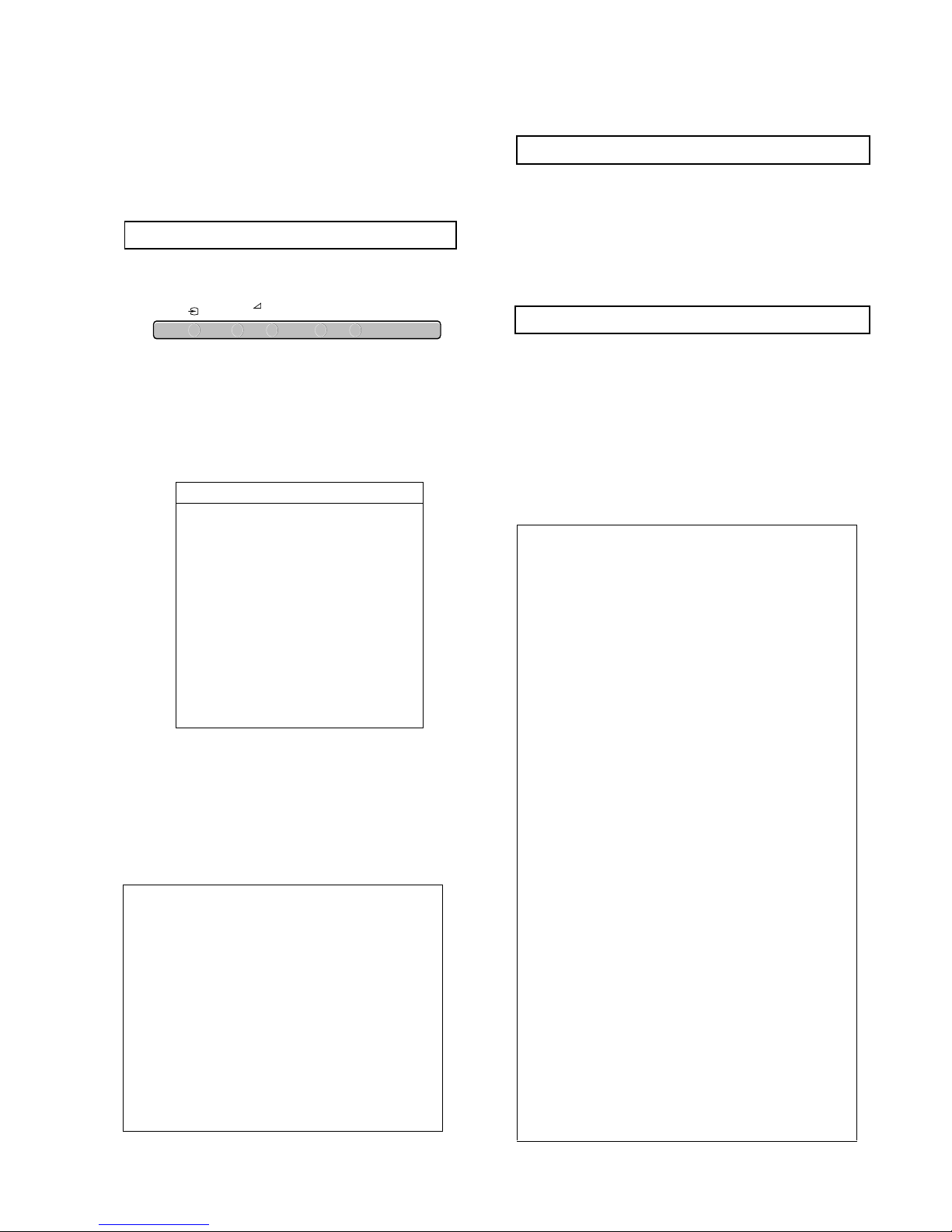
29
SECTION 4
CIRCUIT ADJUSTMENTS
4-1.ELECTRICAL ADJUSTMENTS
Service adjustments to this model can be performed
using the supplied Remote Commander RM-891.
HOW TO ENTER INTO SERVICE MODE
1. Turn on the main power s witch of the set while pre ssing the
PROG + and PROG - buttons on the top panel.
2. ‘TT--’ will appear in the upper right corner of the
screen.
Other status information will also be displayed.
3. Press ‘MENU’ ‘MENU’ on the remote commander to obtain
the following menu on the screen.
4. Move to the corresponding adjustment item by pushing the
OK button up or down.
5. Push the OK button to the right to enter into the required
adjustment.
6. Press the ‘Menu’ button and ‘00’ on the Remote Commander
to quit the Service Mode when all ad justments have been
completed.
CENTRE ADJUSTMENT FOR 4:3 MODE
1. Input a Sony special pattern.
2. Switch the TV into Analogue 4:3 mode.
3. Enter into the service menu by pressing ‘TEST’ ‘TEST’ and
‘MENU’ ‘MENU’ on the remote commander.
4. Select ‘DA SDA9280’ from the ‘Devices’ menu.
5. The ‘DA SDA9280’ menu will appear on screen.
6. Adjust ‘29 BCKPOS’ so that the picture is in the centre of the
screen.
CENTRE ADJUSTMENT FOR DIGITAL MODE
1. Input a Digital test pattern.
2. Switch the TV into Digital mode.
3. Enter into the service menu by pressing ‘TEST’ ‘TEST’ and
‘MENU’ ‘MENU’ on the remote commander.
4. Select ‘Deflect.Con t SDA9361’ from the ‘Devices’ menu.
5. The ‘Deflect.Cont SDA9361’ menu will appear on screen.
6. Adjust ‘48 INT H PHASE’ so that the picture is in the centre
of the screen.
7. Adjust item 1 V size and item 2 V position so that the picture
is in the centre of the screen.
DEVICES
Init TV
Sound MSP3410D
Feature Box S87654
Deflect Cont. SDA9361
Deflect Cont.Subadjust
MCP CXA2101
Col.Dec.Main TDA9144
DA SDA9280
Line 23 Detection
Sub Adjust
Port Expander
Defl.Cont. SDA9361
1 V SIZE ADJ
2 V POSITION ADJ
3 V LINEARITY ADJ
4S CORRECTION ADJ
5 H SIZE ADJ
6 PIN AMP ADJ
7 UPPER CORNER PI N ADJ
8 LOWER CORNER PIN ADJ
9V BOW ADJ
10 PIN PHASE ADJ
11 V ANGLE ADJ
DA SDA9280
1 Int 444 ON
2 Int 422 ON
3Incodc ON
4Incodl OFF
5 Infor 1
6Insneg ON
7Trawid 7
8 Thresh 11
9 VinV Dependant on analogue or digital
10 UinV Dependant on analogue or digital
11 Cgrres 0
12 Cgr OFF
13 Ydel1 Dependant on analogue or digital
14 YinV OFF
15 Ygrres 0
16 Ygr OFF
17 Bcof Dependant on analogue or digital
18 Lcof Dependant on analogue or digital
19 Hcof Dependant on analogue or digital
20 Phacom 2
21 Cor ON
22 Comex OFF
23 Comp OFF
24 Readd 0
25 Ovsamp ON
26 Ovfilt ON
27 Backgr OFF
28 Hsdel 2
29 Bckpos 191
+
–
+
–
PROGR
CONTROL
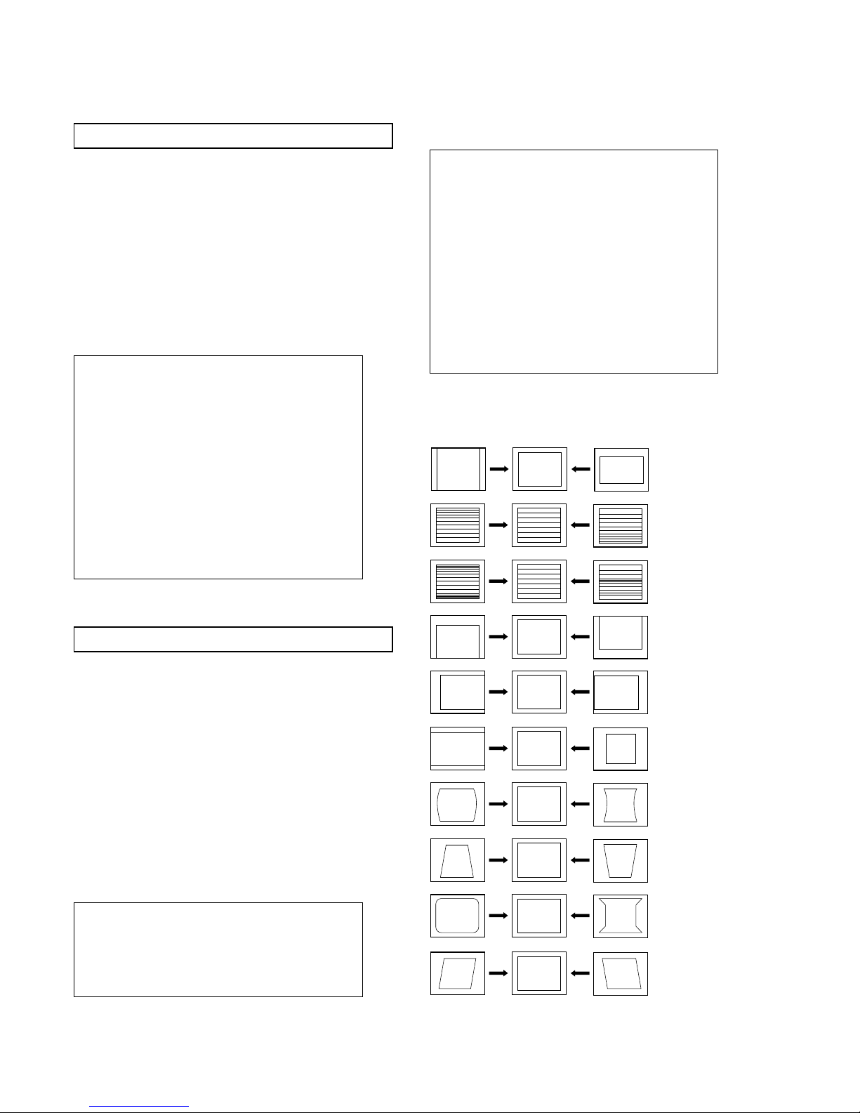
30
DEFLECTION ADJUSTMENT FOR WIDE MODE
1. Input an Phillips pattern.
2. Switch the TV into wide mode.
3. Enter into the service menu by pressing ‘TEST’ ‘TEST’ and
‘MENU’ ‘MENU’ on the remote commander.
4. Select ‘Deflect.Cont SDA9361’ from the ‘Devic es’ menu.
5. The ‘Deflect.Cont SDA9361’ menu will appear on screen.
6. Select and adjust each item to obtain optimum image.
7. Return to the ‘Devices’ menu.
8. Select the ‘Sub Adjust’ menu.
9. Select and adjust each item to obtain optimum image.
10. Repeat above steps in Digital mode.
DEFLECTION ADJUSTMENT FOR SMART MODE
1. Input a Phillips pattern.
2. Switch the TV into smart mode.
3. Enter into the service menu by pressing ‘TEST’ ‘TEST’ and
‘MENU’ ‘MENU’ on the remote commander.
4. Select ‘Deflect.Cont SDA9361’ from the ‘Devic es’ menu.
5. The ‘Deflect.Cont SDA9361’ menu will appear on screen.
6. Select and adjust each item to obtain optimum image.
7. Return to the ‘Devices’ menu.
8. Select the ‘Deflect cont.Subadjust’ menu.
9. Select and adjust each item to obtain optimum image.
10. Return to the ‘Devices’ menu.
11. Select the ‘Subadj ust ’ menu.
12. Select a nd adjust each item to obtain optimum i mage.
13. Repeat above steps in Digital mode.
Defl.Cont. SDA9361
1V SIZE ADJ
2 V POSITION ADJ
3 V LINEARITY ADJ
4 S CORRECTION ADJ
5 H SIZE ADJ
6PIN AMP ADJ
7 UPPER CORNER PIN ADJ
8 LOWER CORNER PIN ADJ
9V BOW ADJ
10 PIN PHASE ADJ
11 V ANGLE ADJ
SUB ADJUSTMENT
1RGB Level 8
2 Menue/Text H-pos -2
3 Extra Framing Window 255
4 4/3 Center
DEFLECTION CONTR.SUBADJUST
1 SMART V SIZE 54
2 SMART V POSITION 220
3 SMART V LINEARITY 215
4 SMART S CORRECTION 236
5SMART H SIZE 80
6SMART PIN AMP 217
7 SMART UPPER CORNER PIN 17
8 SMART LOWER CORNER PIN 189
9 SMART V BOW 243
10 SMART PIN PHASE 202
11 SMART V ANGLE 5
V SIZE
V LIN
S CORRECTION
V CENTRE
H CENTRE
H SIZE
PIN AMP
PIN PHASE
CORNER PIN
V ANGLE
 Loading...