

Page 1

A-D3N-100-11(1)
HD Color Camera Module
Technical Manual
FCB-H11
2008 Sony Corporation
Page 2

Table of Contents
Features ..................................................................... 3
Precautions ................................................................ 4
Locations of Controls ............................................... 5
Basic Functions......................................................... 6
Overview of Functions ................................................ 6
Eclipse ...................................................................... 12
Vibration Specifications ............................................ 12
Initial Settings and Position Preset ........................... 13
Mode Condition ........................................................ 14
Command List ......................................................... 18
VISCA/RS-232C Commands ................................... 18
FCB-H11 Commands ............................................... 24
Specifications .......................................................... 36
2
Page 3

• The CMOS video camera provides 2,000,000
effective picture elements (pixels) that can shoot
high-definition images to offer superior picture
quality.
• The camera is compatible with 8 formats, including
the Full HD (1080i high definition) video format,
which is equivalent to an HD-TV broadcast.
HD: 1080i/59.94, 1080i/50, 720p/59.94, 729p/50
SD: NTSC (CROP), NTSC (SQUEEZE)
PAL (CROP), PAL (SQUEEZE)
•Video outputs
HD: Analog Component
SD: VBS, Y/C
• The camera is equipped with an ×10 optical auto
focus zoom lens.
• The ×12 digital zoom function allows you to zoom up
to ×120, combined with a optical zoom.
•An infrared (IR) Cut-Filter can be disengaged from
the image path for increased sensitivity in low light
environments. The ICR will automatically engage
depending on the ambient light, allowing the camera
to be effective in day/night environment.
• The VISCA is a communication protocol, which
enables the camera to be controlled from a computer.
You can select the baud rate from among 9600 bps,
19200 bps, or 38400 bps. This allows you to remotely
control the camera at a high communication speed.
• The position preset function allows the camera to
store up to six combinations of settings of camera
shooting conditions. Also, the custom preset function
allows you to customize the initial settings of each
function when the power of the camera is turned on.
Overview
Features
With consideration given to environmental
protection, this module is designed to operate with
low power consumption and also incorporates leadfree and halogen-free circuit boards.
3
Page 4

Overview
Precautions
Software
Use of demonstration software developed by Sony
Corporation or use of customer developed application
software may damage hardware, the application
program, or the camera. Sony Corporation is not liable
for any damage that may occur under these conditions.
Operation
Start the camera control software on your computer
after you turn on the camera and the image is
displayed.
Operation and storage locations
Do not shoot images that are extremely bright (e.g.,
light sources, the sun, etc.) for long periods of time. Do
not use or store the camera in the following extreme
conditions:
• Extremely hot or cold places (operating temperature
0 ˚C to +45 ˚C (32 ˚F to 113 ˚F))
•Close to generators of powerful electromagnetic
radiation such as radio or TV transmitters
•Where it is subject to fluorescent light reflections
•Where it is subject to unstable (flickering, etc.)
lighting conditions
•Where it is subject to strong vibration
•Where it is subject to radiation from laser beams
•Where it is subject to internal atmospheric
temperatures that exceed the camera’s operating
temperature range (0 ˚C to +45 ˚C (32 ˚F to 113 ˚F))
Other
Do not apply excessive voltage. (Use only the
specified voltage.) Otherwise, you may get an electric
shock or a fire may occur.
In case of abnormal operation, contact your authorized
Sony dealer or the store where you purchased the
product.
Phenomena specific to CMOS image
sensors
The following phenomena that may appear in images
are specific to CMOS (Complementary Metal Oxide
Semiconductor) image sensors. They do not indicate
malfunctions.
White flecks
Although the CMOS image sensors are produced with
high-precision technologies, fine white flecks may be
generated on the screen in rare cases, caused by cosmic
rays, etc.
This is related to the principle of CMOS image sensors
and is not a malfunction.
The white flecks especially tend to be seen in the
following cases:
•when operating at a high environmental temperature
•when you have raised the master gain (sensitivity)
•when operating in Slow-Shutter mode
Care of the unit
Remove dust or dirt on the surface of the lens with a
blower (commercially available).
The above phenoma may be mitigated somewhat by
turning the power off once, and then turning it on
again.
Aliasing
When fine patterns, stripes, or lines are shot, they may
appear jagged or flicker.
4
Page 5
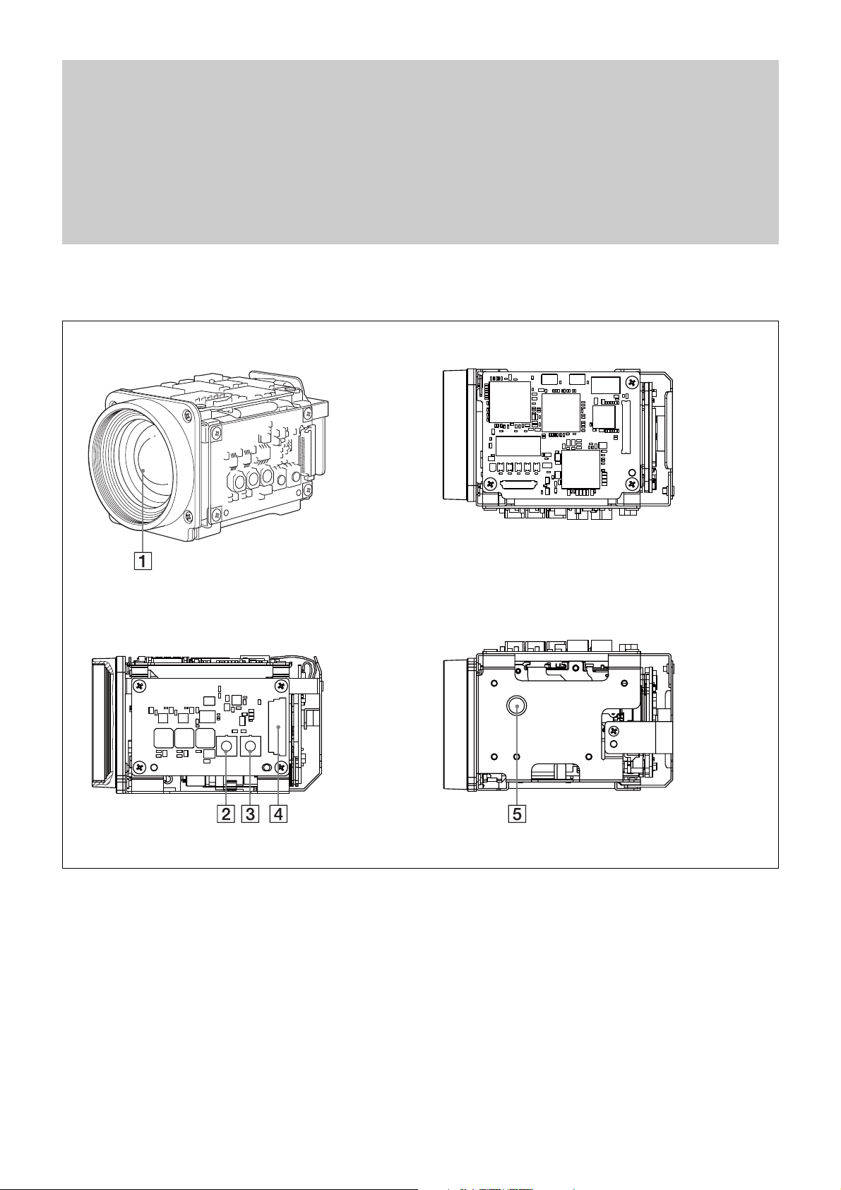
Locations of Controls
Locations of Controls
Front
Right side Bottom
Top
1 Lens
2 WIDE button
3 TELE button
4 CN901 jack
5 Tripod screw hole
When a tripod is used, please use
7
5 mm (
attach it to the camera. Also,
please be sure to attach the tripod
securely.
/32 inches) or less screw to
5
Page 6

Basic Functions
Basic Functions
Overview of Functions
VISCA commands are the basis of camera control.
In general
• Power On/Off
Powers the camera on and off. When the power is
off, the camera is able to accept only the lowest level
of VISCA Commands; the display and other features
are turned off.
• I/F clear
Clears the Command buffer of the FCB-H11 camera.
Clearing the buffer can also be carried out from the
control application software when the power is on.
• Address set
VISCA is a protocol, which normally can support a
daisy chain of up to seven attached devices. In this
case, if addresses from 1 to 7 are assigned to each of
7 devices, you can control seven cameras with the
same personal computer. However, the FCB-H11
camera does not support connection of cameras in a
daisy chain. Therefore, whenever a camera is
connected for the first time, be sure to use the address
set to confirm the address.
• ID Write
Sets the camera ID.
Zoom
The camera employs an 10× optical zoom lens
combined with a digital zoom function allowing you to
zoom up to 120×.
Lens specifications: Optical 10×, f = 5.1 to 51 mm
(F1.8 to F2.1)
The horizontal angle of view is approximately 50
degrees (wide end) to 5.4 degrees (tele end).
Digital Zoom enlarges the center of the subject by
expanding each image in both the vertical and
horizontal directions. When 12× digital zoom is used,
the number of effective picture elements in each
direction reduces to
deteriorates.
You can activate the zoom in the following two ways:
•By pressing the TELE or WIDE buttons on the
camera.
•Using a VISCA Command
Using Standard Mode
Using Variable Mode
There are eight levels of zoom speed.
Direct Mode
Setting the zoom position enables quick
movement to the designated position.
1
/12 and the overall resolution
• Mute
Blanks the screen and sends out a synchronizing
signal.
6
Page 7

Basic Functions
Focus
Focus has the following modes, all of which can be set
using VISCA Commands.
• Auto Focus Mode
The Auto Focus (AF) function automatically adjusts
the focus position to the high frequency content of the
picture in a center measurement area, taking into
consideration the high luminance and strong contrast
components.
The minimum focus distance is 10 mm at the optical
wide end (extreme close-up settings with VISCA
control) (distance from the front end of the lens).
- Normal AF Mode
This is the normal mode for AF operations.
- Interval AF Mode
The mode used for AF movements carried out at
particular intervals. The time intervals for AF
movements and for the timing of the stops can be
set in one-second increments using the Set Time
Command. The initial value for both is set to five
seconds.
- Zoom Trigger Mode
When the zoom is changed with the TELE or the
WIDE buttons, the pre-set value (initially set at 5
seconds) becomes that for AF Mode. Then, it
stops.
• Manual Focus Mode
MF (Manual Focus) has both a Standard Speed Mode
and a Variable Speed Mode. Standard Speed Mode
focuses at a fixed rate of speed. Variable Speed Mode
has eight speed levels that can be set using a VISCA
Command.
• Near Limit Mode
Can be set in a range from about 4.5 m (2000) to 1 cm
(C000).
The focus range is narrowed by excluding the
unnecessary range.
White Balance
White Balance has the following modes, all of which
can be set using VISCA Commands.
• Auto White Balance
This mode computes the white balance value output
using color information from the entire screen. It
outputs the proper value using the color temperature
radiating from a black subject based on a range of
values from 3000 to 7500K.
This mode is the default setting.
• Indoor
3200 K Base Mode
• Outdoor
5800 K Base Mode
• One Push WB
The One Push White Balance mode is a fixed white
balance mode that may be automatically readjusted
only at the request of the user (One Push Trigger),
assuming that a white subject, in correct lighting
conditions and occupying more than
is submitted to the camera.
One Push White Balance data is lost when the power
is turned off. If the power is turned off, reset the One
Push White Balance.
• Manual WB
Manual control of R and B gain, 256 steps each
1
/2 of the image,
To stop the required operation after sending a
Standard Speed command or a Variable Speed
command, send the Stop command.
• One Push Trigger Mode
When a Trigger Command is received, the lens
moves to adjust the focus for the subject. The focus
lens then holds the same position until the next
Trigger Command is input.
• Infinity Mode
The lens is forcibly moved to a position suitable for
an unlimited distance.
7
Page 8

Basic Functions
Automatic Exposure Mode
The variety of AE functions, which allow video signal
to output the optimum image for subjects from low
light conditions to bright light conditions, are
available.
• Full Auto
Auto Iris and Gain, Fixed Shutter Speed (59.94/
NTSC:
• Slow shutter limit
Lower limit of the slow shutter mode in the Full Auto
mode. For the 59.94/NTSC video format, select the
lower limit from among 1/60, 1/30, 1/15, 1/8, 4/1 or
1/2.
For the 50/PAL video format, select the lower limit
from among 1/50, 1/25, 1/12, 1/6, 1/3 or 1/2.
• Shutter Priority
Variable Shutter Speed, Auto Iris and Gain
1
(
slow shutter: 6 steps)
• Iris Priority
Variable Iris (F1.8 to Close, 18 steps), Auto Gain and
Shutter speed.
• Manual
Variable Shutter, Iris and Gain.
• Bright
Variable Iris and Gain (Close to F1.8, 18 steps at
0 dB: F1.8, 6 steps from 0 to 18 dB)
• Spot light
Avoids a situation where the face of the subject is
over-illuminated, and becomes whitish.
1
/60 s, 50/PAL: 1/50 s)
1)
/2 to 1/10,000 s, 21 steps, high speed shutter: 15 steps,
AE – Shutter Priority
The shutter speed can be set freely by the user to a
total of 21 steps – 15 high speeds and 6 low speeds.
1
When the slow shutter is set, the speed can be
1
/15, 1/8, 1/4, or 1/2 s. The picture output is read at a
/30,
normal rate from the memory. The memory is updated
at a low rate from the CCD. AF capability is low.
In high speed mode, the shutter speed can be set up to
1
/10,000 s. The iris and gain are set automatically,
according to the brightness of the subject.
Parameter
15 1/10000 1/10000
14 1/6000 1/6000
13 1/4000 1/3500
12 1/3000 1/2500
11 1/2000 1/1750
10 1/1500 1/1250
0F 1/1000 1/1000
0E 1/725 1/600
0D 1/500 1/425
0C 1/350 1/300
0B 1/250 1/215
0A 1/180 1/150
09 1/125 1/120
08 1/100 1/100
07 1/90 1/75
06 1/60 1/50
05 1/30 1/25
04 1/15 1/12
03 1/8 1/6
02 1/4 1/3
01 1/2 1/2
59.94i 50i
[sec] [sec]
Note
When the low shutter speed is used, Auto Focus and
White Balance may not function fully.
.................................................................................................................................................................................................................................
1) Flicker can be eliminated by setting shutter to:
t1/100 s for NTSC models used in countries with a 50 Hz power supply
frequency.
t1/120 s for PAL models used in countries with a 60 Hz power supply
frequency.
8
Page 9
Basic Functions
AE – Iris Priority
The iris can be set freely by the user to 18 steps
between F1.8 and Close.
The gain and shutter speed are set automatically
according to the brightness of the subject.
parameter IRIS (F1.8) F No. parameter IRIS (F1.8) F No
11 F1.8 08 F8.0
10 F2.0 07 F9.6
0F F2.4 06 F11
0E F2.8 05 F14
0D F3.4 04 F16
0C F4.0 03 F19
0B F4.8 02 F22
0A F5.6 01 F26
09 F6.8 00 CLOSE
AE – Manual
The shutter speed (21 steps), iris (18 steps) and gain (8
steps) can be set freely by the user.
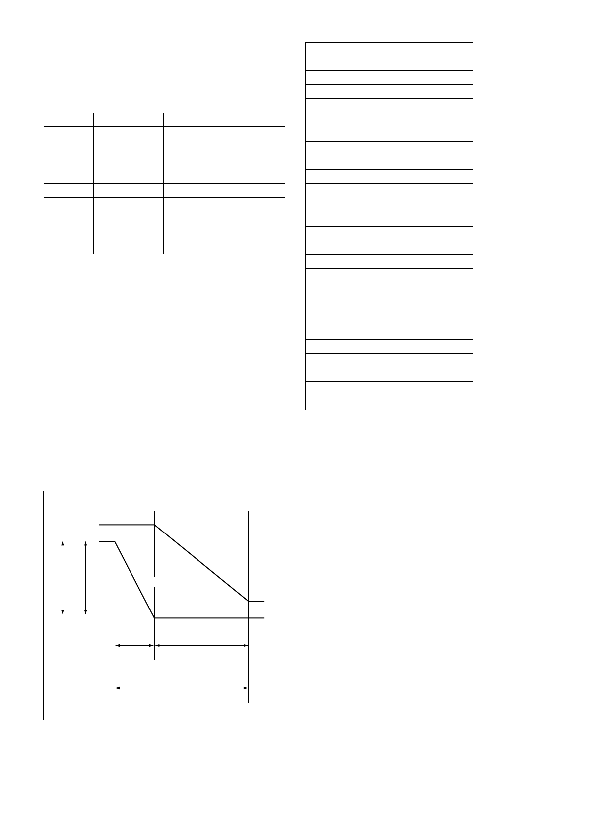
AE – Bright
The bright control function adjusts both the gain and
iris using an internal algorithm according to a
brightness level freely set by the user. Exposure is
controlled by gain when dark and by iris when bright.
As both gain and iris are fixed, this mode is used when
exposing at a fixed camera sensitivity. When switching
from Full Auto or Shutter Priority Mode to Bright
Mode, the current status will be retained for a short
period of time.
Only when the AE mode is set to “Full Auto” or
“Shutter Priority,” the user can switch it to “Bright.”
Gain
AGC
IRIS
MAX
OPEN
IRIS gain curve
AGC gain curve
MIN
CLOSE
Dark Bright
Controlled
by gain
Bright limit controllable
for this unit
Controlled by IRIS
Parameter IRIS (F1.8) GAIN
F No.
17 F1.8 18dB
16 F1.8 15dB
15 F1.8 12dB
14 F1.8 9dB
13 F1.8 6dB
12 F1.8 3dB
11 F1.8 0dB
10 F2.0 0dB
0F F2.4 0dB
0E F2.8 0dB
0D F3.4 0dB
0C F4.0 0dB
0B F4.8 0dB
0A F5.6 0dB
09 F6.8 0dB
08 F8.0 0dB
07 F9.6 0dB
06 F11 0dB
05 F14 0dB
04 F16 0dB
03 F19 0dB
02 F22 0dB
01 F26 0dB
00 CLOSE 0dB
When switching from the Shutter Priority mode to the
Bright mode, the shutter speed set in the Shutter
Priority mode is maintained.
Spot Exposure Mode
In Full Auto AE, the level for the entire screen is
computed and the optimum Auto Iris and Gain levels
are determined. In Spot AE, a particular section of the
subject can be designated, and then that portion of the
image can be weighted and a value computed so that
Iris and Gain can be optimized to obtain an image.
For example, in an image with a lot of movement and
with varying levels of brightness, portions without
much change can be designated as such a “spot,” and
changes to the screen can be minimized in that area.
As shown in the following diagram on the next page, a
range of 16 blocks vertically and 16 blocks
horizontally can be designated.
In the case where the center is designated (shown in
black), the level is computed along with a weighted
value for the surrounding block (shaded), including the
specified portions; and then the Gain and Iris are set.
The value of the designated portions and the
surrounding areas should be calculated as 100%, the
9
Page 10

Basic Functions
rest should be set to 20%. The range of the Spot AE
frame is fixed to 5 blocks vertically and 4 blocks
horizontally.
Horizontal 16
0
123456789ABCDEF
0
1
2
Ver tical 16
3
4
5
6
7
8
9
A
B
C
D
E
F
(8,8)
Exposure Compensation
Exposure compensation is a function which offsets the
internal reference brightness level used in the AE
mode by steps of 1.5 dB.
EXPOSURE Comp Step
Value
0E +10.5dB +7
0D +9dB +6
0C +7.5dB +5
0B +6dB +4
0A +4.5dB +3
09 +3dB +2
08 +1.5dB +1
07 0dB 0
06 –1.5dB –1
05 –3dB –2
04 –4.5dB –3
03 –6dB –4
02 –7.5dB –5
01 –9dB –6
00 –10.5dB –7
Back Light Compensation
When the background of the subject is too bright, or
when the subject is too dark due to shooting in the AE
mode, back light compensation will make the subject
appear clearer.
ICR (IR Cut-Removable) Mode
An infrared (IR) Cut-Filter can be disengaged from the
image path for increased sensitivity in low light
environments. The ICR will automatically engage
depending on the ambient light, allowing the camera to
be effective in day/night environments.
When the auto ICR mode is set to ON, the image
becomes black and white.
Auto ICR Mode
Auto ICR Mode automatically switches the settings
needed for attaching or removing the IR Cut Filter.
With a set level of darkness, the IR Cut Filter is
automatically disabled (ICR ON), and the infrared
sensitivity is increased. With a set level of brightness,
the IR Cut Filter is automatically enabled (ICR OFF).
Also, on systems equipped with an IR light, the
internal data of the camera is used to make the proper
decisions to avoid malfunctions.
Slow shutter – Auto/Manual
When set to “Auto,” ensures that the slow shutter is set
automatically within the range of the lower limit set by
the slow shutter limit command, when the brightness
drops. Effective only when the AE mode is set to “Full
Auto.”
Set to “Slow Shutter Auto” at shipment from the
factory.
Camera ID
The ID can be set up to 65,536 (0000 to FFFF). As this
will be memorized in the nonvolatile memory inside
the camera, data will be saved, regardless of the
“position preset.”
Aperture Control
Aperture control is a function which adjusts the
enhancement of the edges of objects in the picture.
There are 16 levels of adjustment, starting from “no
enhancement.” When shooting text, this control may
help by making the text sharper.
Effect
It consists of the following functions.
• Neg. Art: Negative/Positive Reversal
• Black White: Monochrome Image
10
Page 11

Basic Functions
Gamma
Selects the desired gamma curve of the camera.
• Normal
Reproduces images with the standard video gamma
curve.
• Cinema Type 1
Reproduces images that look lively, providing depth
in images as if you shot them using a film.
• Cinema Type 2
In addition to the features of Cinema Type 1, this
setting is capable of extremely precise description of
the entire exposure zone, from shadowed parts to
highlighted parts, which enables reproduction of a
deeper black.
Freeze
This function captures an image in the field memory of
the camera so that this image can be output
continuously.
The settings are recalled when the power is turned on.
For setting items, see the “Initial Settings and Position
Preset” section on page 13.
Custom Preset
As with the positon preset function, the camera
shooting conditions can be stored and recalled. The
settings are recalled when the power is turned on.
For setting items, see the “Initial Settings and Position
Preset” section on page 13.
Because communication inside the camera is based on V
cycle, the captured image is always the one 3V to 4Vs after
the sending of a Command. Thus, you can not specify a time
period after sending EVEN, ODD or a Command.
Others
Memory (Position Preset)
Using the position preset function, 6 sets of camera
shooting conditions can be stored and recalled.
This function allows you to achieve the desired status
instantly even without adjusting the following items
each time:
• Zoom Position
• Focus Auto/Manual
• Focus Position
• AE Mode
• Shutter control parameters
• Bright Control
• Iris control parameters
• Gain control parameters
• Exposure Compensation On/Off
• Exposure Level
• Backlight Compensation On/Off
• Slow shutter Auto/Manual
• White Balance Mode
• R/B Gain
• Aperture
• ICR Shoot On/Off
11
Page 12
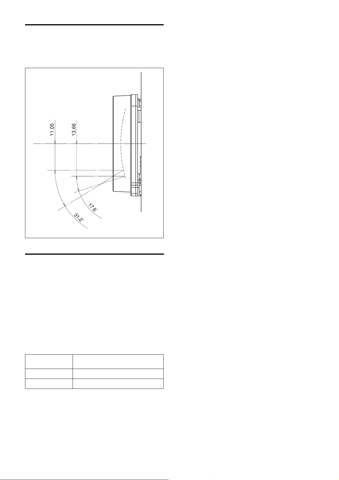
Eclipse
When designing the housing, refer to the dimensional
allowance as shown in the figure below.
Basic Functions
Vibration Specifications
Test Method (Random vibration)
• Fix the camera at the four fixation points of the base
using M2 screws.
• Perform the random vibration test under the
following conditions in the X, Y and Z directions for
20 minutes in each direction.
• The camera vibration specification is to have no
malfunction after this test.
2/s3
Power spectrum density
Effective overall value
Test time
5 to 50 Hz 4.14 m
50 to 100 Hz –36 dB/oct
2
14.3 m/s
20 minutes
{0.043 G2/Hz}
{1.46 G}
12
Page 13

Initial Settings and Position Preset
The initial values are those set at the factory. Settings
for items that will be retained even when the power to
the camera is turned off are indicated by a “a,” those
that will be lost are indicated by an “×.”
Basic Functions
Mode/Position Initial settings
Zoom Position Wide end aa
Focus Position — aa
Focus Auto/Manual Auto aa
Near Limit Setting C000h (1.0 cm) a ×
AF Mode Normal a ×
AF activation time 5 seconds a ×
AF interval time 5 seconds a ×
WB Mode Auto aa
WB Data (Rgain, Bgain) — aa
One Push WB Data — a ×
AE Mode Full Auto aa
Slow Shutter Mode On aa
Shutter Position 1/60sec (59.94/NTSC),
1/50sec (50/PAL)
Iris Position — aa
Gain Position — aa
Bright Position — aa
Exposure Compensation On/Off Off aa
Exposure Compensation Amount ±0 aa
Backlight On/Off Off aa
Spot AE On/Off Off a ×
Spot AE position setting X=8, Y=8 a ×
Gamma Normal a ×
Key Lock Off a ×
Aperture Level 8 aa
Freeze On/Off Off ××
Picture Effect Off a ×
Mute On/Off Off ××
D-Zoom Limit x4 aa
AutoSlowShutterLimit Off aa
ICR On/Off Off aa
Auto ICR On/Off Off aa
Auto ICR Threshold Level 0Ch aa
Custom Memroy position
preset
aa
presets 0 to 5
Notes
• The number of times data can be written to the EEPROM (by executing Position Preset) is limited.
• Camera ID data will be saved regardless of the position preset.
13
Page 14

Memory Command
Basic Functions
Other Status
During displaying
3)
Initializing
2)
IFC
1)
Power Off
ntil the video signal is output. Or the
Mode Power On
Command a still image
Address Set aa aaaa
IF_Clear aa aaaa
CAM_Power On a ××aa ×
CAM_Power Off a ××aa ×
Mode Condition
Basic settings
CAM Version Inq. aaaaaa
CAM_Power Inq. aaaaaa
BlockInquiry ×××aa×
InquiryCommand (and similar commands) ×× ×aa ×
period from the time the CAM Power ON command is sent, until Completion is returned.
1) DC power is being supplied, but the camera has been turned off by a VISCA command.
2) The period from the time IF Clear is sent, until the Reply Packet is returned.
3) The period from the time DC power is turned on or the camera is turned on via a VISCA command, and the lens is initialized, u
14
Page 15

Basic Functions
Memory Recall
During displaying
Zoom Direct Focus Direct AF ON
Memory Recall
During displaying
×× ×
4)
ntil the video signal is output. Or the period from the time the CAM Power ON
White balance mode
ntil the video signal is output. Or the period from the time the CAM Power ON
3)
Initializing
2)
IFC
1)
Power Off
Mode Power On
3)
Initializing
2)
IFC
1)
Power Off
Mode Power On
×××aaaaa ××
ЧЧЧЧЧЧЧa ××
Command a still image
CAM_Zoom Tele/Wide/Stop ××××aa ××
CAM_Zoom Direct ×××aaa ××
Zoom/Focus
D-Zoom Limit ××××aa ××
CAM_Focus Far/Near/Stop ×××a ××××
CAM_Focus Direct ×××aa ×× ×
CAM_Focus Mode (Auto/Manual) ×××a × a ××
CAM_Focus One Push Trigger ×××a ××××
CAM_Focus Infinity ×××a × a ××
CAM_Focus Near Limit ×××a × a ××
command is sent, until Completion is returned.
1) DC power is being supplied, but the camera has been turned off by a VISCA command.
2) The period from the time IF Clear is sent, until the Reply Packet is returned.
3) The period from the time DC power is turned on or the camera is turned on via a VISCA command, and the lens is initialized, u
White Balance
Command Auto Indoor Outdoor One Push Manual a still image
CAM_WB Auto/Indoor/Outdoor/
OnePUshWB/Manual
CAM_WB One Push Trigger ЧЧЧЧЧЧa
CAM_WB R(B) Gain
Reset/Up/Down/Direct
command is sent, until Completion is returned.
1) DC power is being supplied, but the camera has been turned off by a VISCA command.
2) The period from the time IF Clear is sent, until the Reply Packet is returned.
3) The period from the time DC power is turned on or the camera is turned on via a VISCA command, and the lens is initialized, u
4) Commands are ignored during a One Push AWB operation.
15
Page 16

Memory Recall
During displaying
Basic Functions
Exposure mode
3)
aaaa ××
4)
Initializing
2)
IFC
1)
Power Off
ntil the video signal is output. Or the period from the time the CAM Power ON
ЧЧЧЧЧa ××a ××
×××a aaaaa ××
Mode Power On
Command Full Auto Bright Shutter Pri Iris Pri SPOT Light Manual a still image
Exposure
CAM_AE
5)
Full Auto/Manual/Shutter Pri/ ×××aa
Iris Pri/Bright/Spot Light
CAM_AE Bright ×××aaa ××× × ×
CAM_Slow Shutter Limit ON/OFF ×××a aaaaa ××
CAM_Shutter Reset/Up/Down/Direct
CAM_Iris Reset/Up/Down/Direct ЧЧЧЧЧЧa × a ××
CAM_Gain Reset/Up/Down/Direct ЧЧЧЧЧЧЧЧa ××
6)
command is sent, until Completion is returned.
CAM_Bright Reset/Up/Down/Direct ××××a × ××× × ×
CAM_ExComp On/Off ×××a aaaaa ××
CAM_ExComp Reset/Up/Down/Direct
CAM_Backlight On/Off ×××a ×××a ×× ×
1) DC power is being supplied, but the camera has been turned off by a VISCA command.
2) The period from the time IF Clear is sent, until the Reply Packet is returned.
3) The period from the time DC power is turned on or the camera is turned on via a VISCA command, and the lens is initialized, u
4) a: Only when the camera changes to BRIGHT mode from Full Auto or SHUTTER Pri mode.
5) You are not allowed to adjust the slow shutter setting while using Digital Effect.
6) ×: This is not allowed when EX-COMP is set to OFF.
16
Page 17

Memory Recall
During displaying
Basic Functions
Picture Effect ON
Slow Shutter
3)
Initializing
2)
IFC
1)
Power Off
ntil the video signal is output. Or the period from the time the
Others
Mode Power On
Command Status a still image
CAM_Aperture Reset/Up/Down/Direct ×××aa ××
CAM_PictureEffect Off/Nega/B&W ×××aa ××
ICR On/Off ××××aa ×
Auto ICR On/Off ЧЧЧЧЧa ×
Auto ICR Threshold Level ЧЧЧЧЧa ×
CAM Power ON command is sent, until Completion is returned.
1) DC power is being supplied, but the camera has been turned off by a VISCA command.
2) The period from the time IF Clear is sent, until the Reply Packet is returned.
3) The period from the time DC power is turned on or the camera is turned on via a VISCA command, and the lens is initialized, u
17
Page 18

VISCA1) /RS-232C
Commands
Use of RS-232C control software which has been
developed based upon this command list may cause
malfunction or damage to hardware and software.
Sony Corporation is not liable for any such damage.
Command List
Command List
Overview of VISCA
In VISCA, the side outputting commands, for example,
a computer, is called the controller, while the side
receiving the commands, such as an FCB-H11, is
called the peripheral device. The FCB-H11 serves as a
peripheral device in VISCA. In VISCA, up to seven
peripheral devices like the FCB-H11 can be connected
to one controller using communication conforming to
the RS-232C standard. The parameters of RS-232C are
as follows.
• Communication speed: 9600 bps/19200 bps/
38400 bps
• Data bits : 8
• Start bit : 1
• Stop bit : 1
• Non parity
Flow control using XON/XOFF and RTS/CTS, etc., is
not supported.
................................................................................................................................................................................................................................
1)VISCA is a protocol which controls consumer camcorders developed by Sony. “VISCA” is a trademark of Sony Corporation.
18
Page 19

VISCA Communication
Specifications
Command List
VISCA packet structure
The basic unit of VISCA communication is called a
packet (Fig.1). The first byte of the packet is called the
header and comprises the sender’s and receiver’s
addresses. For example, the header of the packet sent
to the FCB-H11 assigned address 1 from the controller
(address 0) is hexadecimal 81H. The packet sent to the
FCB-H11 assigned address 2 is 82H. In the command
Packet (3 to 16 bytes)
Message (1 to 14 bytes)Header
Byte 1 Byte 2 Byte 3
Sender’s
10
Bit 7
(MSB)
address
Bit 6 Bit 5 Bit 4 Bit 3 Bit 2 Bit 1 Bit 0
Receiver’s address
(LSB)
list, as the header is 8X, input the address of the
FCB-H11 at X. The header of the reply packet from
the FCB-H11 assigned address 1 is 90H. The packet
from the FCB-H11 assigned address 2 is A0H.
Some of the commands for setting FCB-H11 units can
be sent to all devices at one time (broadcast). In the
case of broadcast, the header should be hexadecimal
88H. When the terminator is FFH, it signifies the end
of the packet.
Terminator
FF
11111111
Bit 7
Bit 6 Bit 5 Bit 4 Bit 3 Bit 2 Bit 1 Bit 0
(MSB)
(LSB)
Fig. 1 Packet structure
Note
Fig. 1 shows the packet structure, while Fig. 2 shows
the actual waveform. Data flow will take place with
the LSB first.
Start
Bit 0 Bit 1 Bit 2 Bit 3 Bit 4 Bit 5
bit
(LSB)
Fig. 2 Actual waveform for 1 byte.
Timing Chart
As VISCA Command processing can only be carried
out one time in a Vertical cycle, it takes the maximum
1V cycle time for an ACK/Completion to be returned.
If the Command/ACK/Completion communication
time can be cut shorter than the 1V cycle time, then
every 1V cycle can receive a Command.
From this point, if 2 or more commands in a row are to
be sent, wait for the first command (for normal
commands, an ACK or an error message, for query
commands, an Inquiry Packet) to be carried out before
sending the next one.
1 byte
Bit 6 Bit 7
Stop
bit.
(MSB)
General Commands
Command
Query Commands
Command
ACK Completion
More than 16.7 msec
(20msec 50Hz system)
More than 16.7 msec
(20msec 50Hz system)
Inquiry Packet
16 Byte
19
Page 20

Command List
Command and inquiry
● Command
Sends operational commands to the FCB-H11.
● Inquiry
Used for inquiring about the current state of the
FCB-H11.
Command Packet Note
Inquiry 8X QQ RR ... FF QQ
1)
QQ = 01 (Command), 09 (Inquiry)
2)
RR = 00 (Interface), 04 (camera 1), 06 (Pan/Tilter)
X = 1 to 7: FCB-H11 address
1)
= Command/Inquiry,
2)
RR
= category code
Responses for commands and inquiries
● ACK message
Returned by the FCB-H11 when it receives a
command. No ACK message is returned for
inquiries.
● Completion message
Returned by the FCB-H11 when execution of
commands or inquiries is completed. In the case of
inquiry commands, it will contain reply data for the
inquiry after the 3rd byte of the packet. If the ACK
message is omitted, the socket number will contain a
0.
Reply Packet Note
Ack X0 4Y FF Y = socket number
Completion (commands) X0 5Y FF Y = socket number
Completion (Inquiries) X0 5Y ... FF Y = socket number
X = 9 to F: FCB-H11 address + 8
Socket number
When command messages are sent to the FCB-H11, it
is normal to send the next command message after
waiting for the completion message or error message
to return. However to deal with advanced uses, the
FCB-H11 has two buffers (memories) for commands,
so that up to two commands including the commands
currently being executed can be received. When the
FCB-H11 receives commands, it notifies the sender
which command buffer was used using the socket
number of the ACK message.
As the completion message or error message also has a
socket number, it indicates which command has ended.
Even when two command buffers are being used at
any one time, an FCB-H11 management command and
some inquiry messages can be executed.
The ACK message is not returned for these commands
and inquiries, and only the completion message of
socket number 0 is returned.
Command execution cancel
To cancel a command which has already been sent,
send the Cancel command as the next command. To
cancel one of any two commands which have been
sent, use the cancel message.
Cancel Packet Note
Cancel 8X 2Y FF Y = socket number
X = 1 to 7: FCB-H11 address, Y = socket number
The Command canceled error message will be returned
for this command, but this is not a fault. It indicates
that the command has been canceled.
● Error message
When a command or inquiry command could not be
executed or failed, an error message is returned
instead of the completion message.
Error Packet Description
X0 6Y 02 FF Syntax Error
X0 6Y 03 FF Command buffer full
X0 6Y 04 FF Command cancelled
X0 6Y 05 FF No socket (to be cancelled)
X0 6Y 41 FF Command not executable
X = 9 to F: FCB-H11 address + 8, Y = socket number
20
Page 21

VISCA Device Setting
Command
Before starting control of the FCB-H11, be sure to
send the Address command and the IF_Clear
command using the broadcast function.
For VISCA network administration
● Address
Sets an address of a peripheral device. Use when
initializing the network, and receiving the following
network change message.
● Network Change
Sent from the peripheral device to the controller
when a device is removed from or added to the
network. The address must be re-set when this
message is received.
Command List
Packet Note
Address 88 30 01 FF Always broadcasted.
Network Change X0 38 FF
X = 9 to F: FCB-H11 address + 8
VISCA interface command
● IF_Clear
Clears the command buffers in the FCB-H11 and
cancels the command currently being executed.
Command Packet Reply Packet Note
IF_Clear 8X 01 00 01FF Y0 50 FF
IF_Clear (broadcast) 88 01 00 01 FF 88 01 00 01 FF
X = 1 to 7: FCB-H11 address (For inquiry packet)
Y = 9 to F: FCB-H11 address +8 (For reply packet)
VISCA interface and inquiry
● CAM_VersionInq
Returns information on the VISCA interface.
Inquiry Inquiry Packet Reply Packet Description
CAM_VersionInq 8X 09 00 02 FF Y0 50 GG GG HH HH JJ JJ KK FF GGGG: Vender ID
(0020: Sony)
HHHH = Model ID
044B: FCB-H11
JJJJ = ROM revision
KK = Maximum socket # (02)
X = 1 to 7: FCB-H11 address (For inquiry packet)
Y = 9 to F: FCB-H11 address +8 (For reply packet)
21
Page 22

VISCA Command/ACK Protocol
Command List
Command Command Message Reply Message
General Command 81 01 04 38 02 FF 90 41 FF (ACK)+90 51 FF
(Example) (Completion)
90 42 FF 90 52 FF
81 01 04 38 FF 90 60 02 FF (Syntax Error)
(Example)
81 01 04 38 02 FF 90 60 03 FF
(Example) (Command Buffer Full)
81 01 04 08 02 FF 90 61 41 FF
(Example) (Command Not Executable)
90 62 41FF
Inquiry Command 81 09 04 38 FF 90 50 02 FF (Completion)
(Example)
81 09 05 38 FF 90 60 02 FF (Syntax Error)
(Example)
Address Set 88 30 01 FF 88 30 02 FF
IF_Clear(Broadcast) 88 01 00 01 FF 88 01 00 01 FF
IF_Clear (For x) 8x 01 00 01 FF z0 50 FF (Completion)
Command Cancel 8x 2y FF z0 6y 04 FF
(Command Canceled)
z0 6y 05 FF (No Socket)
Comments
Returns ACK when a command has been accepted, and
Completion when a command has been executed.
Accepted a command which is not supported or a command
lacking parameters.
There are two commands currently being executed, and the
command could not be accepted.
Could not execute the command in the current mode.
ACK is not returned for the inquiry command.
Accepted an incompatible command.
Returned the device address to +1.
Returned the same command.
ACK is not returned for this command.
Returned when the command of the socket specified is canceled.
Completion for the command canceled is not returned.
Returned when the command of the specified socket has already
been completed or when the socket number specified is wrong.
22
Page 23

VISCA Camera-Issued Messages
ACK/Completion Messages
Command List
Command Messages
ACK z0 4y FF
(y:Socket No.)
Completion z0 5y FF
(y:Socket No.)
z = Device address + 8
Error Messages
Command Messages
Syntax Error z0 60 02 FF
Command Buffer Full z0 60 03 FF
Command Canceled z0 6y 04 FF
(y:Socket No.)
No Socket z0 6y 05 FF
(y:Socket No.)
Command Not Executable z0 6y 41 FF
(y:Execution command
Socket No. Inquiry command:0)
Comments
Returned when the command is accepted.
Returned when the command has been executed.
Comments
Returned when the command format is different or when a command with illegal
command parameters is accepted.
Indicates that two sockets are already being used (executing two commands) and the
command could not be accepted when received.
Returned when a command which is being executed in a socket specified by the
cancel command is canceled. The completion message for the command is not
returned.
Returned when no command is executed in a socket specified by the cancel
command, or when an invalid socket number is specified.
Returned when a command cannot be executed due to current conditions. For
example, when commands controlling the focus manually are received during auto
focus.
Network Change Message
Command Message
Network Change z0 38 FF
Comments
Issued when power is being routed to the camera.
23
Page 24

Command List
FCB-H11 Commands
FCB-H11 Command List (1/3)
Command Set Command Command Packet Comments
AddressSet Broadcast 88 30 01 FF Address setting
IF_Clear Broadcast 88 01 00 01 FF I/F Clear
CommandCancel 8x 2p FF p: Socket No.(=1or2)
CAM_Power On 8x 01 04 00 02 FF Power ON/OFF
Off 8x 01 04 00 03 FF
CAM_Zoom Stop 8x 01 04 07 00 FF
Tele(Standard) 8x 01 04 07 02 FF
Wide(Standard) 8x 01 04 07 03 FF
Tele(Variable) 8x 01 04 07 2p FF p=0 (Low) to 7 (High)
Wide(Variable) 8x 01 04 07 3p FF
Direct 8x 01 04 47 0p 0q 0r 0s FF pqrs: Zoom Position
CAM_DZoom D-Zoom Limit 8x 01 04 26 0p FF p=0 (x1), 1 (x1.5), 2 (x2), 3 (x4), 4 (x8), 5 (x12)
CAM_Focus Stop 8x 01 04 08 00 FF
Far(Standard) 8x 01 04 08 02 FF
Near(Standard) 8x 01 04 08 03 FF
Far(Variable) 8x 01 04 08 2p FF p=0 (Low) to 7 (High)
Near(Variable) 8x 01 04 08 3p FF
Direct 8x 01 04 48 0p 0q 0r 0s FF pqrs: Focus Position
Auto Focus 8x 01 04 38 02 FF AF ON/OFF
Manual Focus 8x 01 04 38 03 FF
Auto/Manual 8x 01 04 38 10 FF
One Push Trigger 8x 01 04 18 01 FF One Push AF Trigger
Infinity 8x 01 04 18 02 FF Forced infinity
Near Limit 8x 01 04 28 0p 0q 0r 0s FF pqrs: Focus Near Limit Position
CAM_AFMode Normal AF 8x 01 04 57 00 FF AF operation mode
Interval AF 8x 01 04 57 01 FF
ZOOM Trigger AF 8x 01 04 57 02 FF
Active/Interval Time 8x 01 04 27 0p 0q 0r 0s FF pq: Active Time, rs: Interval
CAM_ZoomFocus Direct 8x 01 04 47 0p 0q 0r 0s pqrs: Zoom Position
0t 0u 0v 0w FF tuvw: Focus Position
CAM_WB Auto 8x 01 04 35 00 FF Normal Auto
Indoor 8x 01 04 35 01 FF Indoor mode
Outdoor 8x 01 04 35 02 FF Outdoor mode
One Push WB 8x 01 04 35 03 FF One Push WB mode
Manual 8x 01 04 35 05 FF Manual Control mode
One Push Trigger
CAM_RGain Reset 8x 01 04 03 00 FF Manual Control of R Gain
Up 8x 01 04 03 02 FF
Down 8x 01 04 03 03 FF
Direct 8x 01 04 43 00 00 0p 0q FF pq: R Gain
CAM_BGain Reset 8x 01 04 04 00 FF Manual Control of B Gain
Up 8x 01 04 04 02 FF
Down 8x 01 04 04 03 FF
Direct 8x 01 04 44 00 00 0p 0q FF pq: B Gain
1)
8x 01 04 10 05 FF One Push WB Trigger
24
Page 25

FCB-H11 Command List (2/3)
Command Set Command Command Packet Comments
CAM_AE Full Auto 8x 01 04 39 00 FF Full Auto
Manual 8x 01 04 39 03 FF Manual Control mode
Shutter Priority 8x 01 04 39 0A FF Shutter Priority Automatic Exposure mode
Iris Priority 8x 01 04 39 0B FF Iris Priority Automatic Exposure mode
Bright 8x 01 04 39 0D FF Bright Mode (Manual control)
SpotLight 8x 01 04 39 10 FF Spot light mode
CAM_SlowShutter Auto 8x 01 04 5A 02 FF AutoSlowShutter On/Off
Manual 8x 01 04 5A 03 FF
AutoSlowShutterLimit 8x 01 04 2A 0p 00 FF 59.94 Hz system: p = 0 (1/60), 1 (1/30), 2 (1/15), 3 (1/8),
4 (1/4), 5 (1/2)
50 Hz system: p = 0 (1/50), 1 (1/25), 2 (1/12), 3 (1/6).
4 (1/3), 5 (1/2)
CAM_Shutter Reset 8x 01 04 0A 00 FF Shutter Setting
Up 8x 01 04 0A 02 FF
Down 8x 01 04 0A 03 FF
Direct 8x 01 04 4A 00 00 0p 0q FF pq: Shutter Position
CAM_Iris Reset 8x 01 04 0B 00 FF Iris Setting
Up 8x 01 04 0B 02 FF
Down 8x 01 04 0B 03 FF
Direct 8x 01 04 4B 00 00 0p 0q FF pq: Iris Position
CAM_Gain Reset 8x 01 04 0C 00 FF Gain Setting
Up 8x 01 04 0C 02 FF
Down 8x 01 04 0C 03 FF
Direct 8x 01 04 4C 00 00 0p 0q FF pq: Gain Position
CAM_Bright Reset 8x 01 04 0D 00 FF Bright Setting
Up 8x 01 04 0D 02 FF
Down 8x 01 04 0D 03 FF
Direct 8x 01 04 4D 00 00 0p 0q FF pq: Bright Position
CAM_ExpComp On 8x 01 04 3E 02 FF Exposure Compensation ON/OFF
Off 8x 01 04 3E 03 FF
Reset 8x 01 04 0E 00 FF Exposure Compensation Amount Setting
Up 8x 01 04 0E 02 FF
Down 8x 01 04 0E 03 FF
Direct 8x 01 04 4E 00 00 0p 0q FF pq: ExpComp Position
CAM_BackLight On 8x 01 04 33 02 FF Back Light Compensation ON/OFF
Off 8x 01 04 33 03 FF
CAM_SpotAE On 8x 01 04 59 02 FF Setting for Spot AE
Off 8x 01 04 59 03 FF
Position 8x 01 04 29 0p 0q 0r 0s FF pq: X (0 to F), rs: Y(0 to F)
CAM_Aperture Reset 8x 01 04 02 00 FF Aperture Control
Up 8x 01 04 02 02 FF
Down 8x 01 04 02 03 FF
Direct 8x 01 04 42 00 00 0p 0q FF pq: Aperture Gain
CAM_Gamma Normal 8x 01 04 5B 00 FF Gamma setting
Cinema Type 1 8x 01 04 5B 01 FF
Cinema Type 2 8x 01 04 5B 02 FF
CAM_Freeze On 8x 01 04 62 02 FF Freeze On/Off
Off 8x 01 04 62 03 FF
Command List
25
Page 26

FCB-H11 Command List (3/3)
Command Set Command Command Packet Comments
CAM_PictureEffect Off 8x 01 04 63 00 FF Picture Effect Setting
Neg.Art 8x 01 04 63 02 FF
B&W 8x 01 04 63 04 FF
CAM_ICR On 8x 01 04 01 02 FF Infrared Mode On/Off
Off 8x 01 04 01 03 FF
CAM_AutoICR On 8x 01 04 51 02 FF Auto dark-field mode On/Off
Off 8x 01 04 51 03 FF
Threshold 8x 01 04 21 00 00 0p 0q FF pq: ICR ON t OFF Threshold Level
CAM_Memory Reset 8x 01 04 3F 00 0p FF p: Memory Number (=0 to 5)
Set 8x 01 04 3F 01 0p FF
Recall 8x 01 04 3F 02 0p FF
CAM_CUSTOM Reset 8x 01 04 3F 00 7F FF
Set 8x 01 04 3F 01 7F FF
Recall 8x 01 04 3F 02 7F FF
CAM_Mute On 8x 01 04 75 02 FF Mute On/Off
Off 8x 01 04 75 03 FF
On/Off 8x 01 04 75 10 FF
CAM_KeyLock Off 8x 01 04 17 00 FF Key operation enable/disable
On 8x 01 04 17 02 FF
CAM_IDWrite 8x 01 04 22 0p 0q 0r 0s FF pqrs: Camera ID (=0000 to FFFF)
CAM_RegisterValue 8x 01 04 24 mm 0p 0q FF mm: Register number (00 to 7F)
pp: Register Value (00 to FF)
Command List
1)After an ACK to a One Push White Balance Trigger is sent until the operation is completed, “Not Executable” is sent as a reply when any
other commands are received.
When a slow shutter speed (1/30, 1/25 or lower) is selected, the time needed for the One Push White Balance adjustment will be longer.
26
Page 27

Command List
FCB-H11 Inquiry Command List (1/2)
Inquiry Command Command Packet Inquiry Packet Comments
CAM_PowerInq 8x 09 04 00 FF y0 50 02 FF On
y0 50 03 FF Off
CAM_ZoomPosInq 8x 09 04 47 FF y0 50 0p 0q 0r 0s FF pqrs: Zoom Position
CAM_DZoomLimitInq 8x 09 04 26 FF y0 50 0p FF p= 0 (x1), 1 (x1/5), 2 (x2), 3 (x4), 4 (x8),
5 (x12)
CAM_FocusModeInq 8x 09 04 38 FF y0 50 02 FF Auto Focus
y0 50 03 FF Manual Focus
CAM_FocusPosInq 8x 09 04 48 FF y0 50 0p 0q 0r 0s FF pqrs: Focus Position
CAM_FocusNearLimitInq 8x 09 04 28 FF y0 50 0p 0q 0r 0s FF pqrs: Focus Near Limit Position
CAM_AFModeInq 8x 09 04 57 FF y0 50 00 FF Normal AF
y0 50 01 FF Interval AF
y0 50 02 FF Zoom Trigger AF
CAM_AFTimeSettingInq 8x 09 04 27 FF y0 50 0p 0q 0r 0s FF pq: Active Time, rs: Interval
CAM_WBModeInq 8x 09 04 35 FF y0 50 00 FF Auto
y0 50 01 FF In Door
y0 50 02 FF Out Door
y0 50 03 FF One Push WB
y0 50 05 FF Manual
CAM_RGainInq 8x 09 04 43 FF y0 50 00 00 0p 0q FF pq: R Gain
CAM_BGainInq 8x 09 04 44 FF y0 50 00 00 0p 0q FF pq: B Gain
CAM_AEModeInq 8x 09 04 39 FF y0 50 00 FF Full Auto
y0 50 03 FF Manual
y0 50 0A FF Shutter Priority
y0 50 0B FF Iris Priority
y0 50 0D FF Bright
y0 50 10 FF Spot Light
CAM_SlowShutterModeInq 8x 09 04 5A FF y0 50 02 FF Auto
y0 50 03 FF Manual
CAM_AutoSlowShutterLimitInq 8x 09 04 2A FF y0 50 0p 00 FF 59.94 Hz system: p = 0 (1/60), 1 (1/30),
2 (1/15), 3 (1/8), 4 (1/4), 5 (1/2)
50 Hz system: p = 0 (1/50), 1 (1/25), 2 (1/12),
3 (1/6), 4 (1/3), 5 (1/2)
CAM_ShutterPosInq 8x 09 04 4A FF y0 50 00 00 0p 0q FF pq: Shutter Position
CAM_IrisPosInq 8x 09 04 4B FF y0 50 00 00 0p 0q FF pq: Iris Position
CAM_GainPosInq 8x 09 04 4C FF y0 50 00 00 0p 0q FF pq: Gain Position
CAM_BrightPosInq 8x 09 04 4D FF y0 50 00 00 0p 0q FF pq: Bright Position
CAM_ExpCompModeInq 8x 09 04 3E FF y0 50 02 FF On
y0 50 03 FF Off
CAM_ExpCompPosInq 8x 09 04 4E FF y0 50 00 00 0p 0q FF pq: ExpComp Position
CAM_BackLightModeInq 8x 09 04 33 FF y0 50 02 FF On
y0 50 03 FF Off
CAM_SpotAEModeInq 8x 09 04 59 FF y0 50 02 FF On
y0 50 03 FF Off
CAM_SpotAEPosInq 8x 09 04 29 FF y0 50 0p 0q 0r 0s FF pq: X position, rs: Y position
CAM_ApertureInq 8x 09 04 42 FF y0 50 00 00 0p 0q FF pq: Aperture Gain
CAM_GammaInq 8x 09 04 5B FF y0 50 00 FF Normal
y0 50 01 FF Cinema Type 1
y0 50 02 FF Cinema Type 2
CAM_FreezeModeInq 8x 09 04 62 FF y0 50 02 FF On
y0 50 03 FF Off
27
Page 28

Command List
FCB-H11 Inquiry Command List (2/2)
Inquiry Command Command Packet Inquiry Packet Comments
CAM_PictureEffectModeInq 8x 09 04 63 FF y0 50 00 FF Off
y0 50 02 FF Neg.Art
y0 50 04 FF B&W
CAM_MemoryInq 8x 09 04 3F FF y0 50 pp FF pp: Memory number last operated.
CAM_ICRModeInq 8x 09 04 01 FF y0 50 02 FF On
y0 50 03 FF Off
CAM_AutoICRModeInq 8x 09 04 51 FF y0 50 02 FF On
y0 50 03 FF Off
CAM_AutoICRThresholdInq 8x 09 04 21 FF y0 50 00 00 0p 0q FF pq: ICR ON t OFF Threshold Level
CAM_MuteModeInq 8x 09 04 75 FF y0 50 02 FF On
y0 50 03 FF Off
CAM_KeyLockInq 8x 09 04 17 FF y0 50 00 FF Off
y0 50 02 FF On
CAM_IDInq 8x 09 04 22 FF y0 50 0p 0q 0r 0s FF pqrs: Camera ID
CAM_VersionInq 8x 09 00 02 FF y0 50 00 20 mnpq: Model Code “(044A)”
mn pq rs tu vw FF rstu: ROM version
vw: Socket Number (=02)
See page 21.
CAM_ReplyIntervalTimeInq 8x 09 04 6A FF y0 50 00 00 0p 0p FF pp: Interval Time
CAM_RegisterValueInq 8x 09 04 24 mm FF y0 50 0p 0p FF mm: Register number, pp: Register value
28
Page 29

Command List
FCB-H11 Block Inquiry Command List
Lens control system inquiry commands ....... Command Packet 8x 09 7E 7E 00 FF
Byte Bit Comments
7
6
5
4
0
3
2
1
0
70 Completion Message (50h)
61
50
41
1
30
20
10
00
70
60
50
40
2
3
2
1
0
70
60
50
40
3
3
2
1
0
70
60
50
40
4
3
2
1
0
70
60
50
40
5
3
2
1
0
Destination Address
Source Address
Zoom Position (HH)
Zoom Position (HL)
Zoom Position (LH)
Zoom Position (LL)
Byte Bit Comments
70
60
50
40
6
3
2
1
0
70
60
50
40
7
3
2
1
0
70
60
50
40
8
3
2
1
0
70
60
50
40
9
3
2
1
0
70
60
50
40
10
3
2
1
0
70
60
50
40
11
3
2
1
0
Focus Near Limit (H)
Focus Near Limit (L)
Focus Position (HH)
Focus Position (HL)
Focus Position (LH)
Focus Position (LL)
Byte Bit Comments
70
60
50
40
12
30
20
10
00
70
60
50
13 4 AF Mode
3 0: Normal 1: Interval
2: Zoom Trigger
20
11
0 Focus Mode 1: Auto 0: Manual
70
60
50
40
30
14
2 Gamma Memory Recall
1:Executing, 0: Stopped
1 Focus command
1: Executing, 0: Stopped
0 Zoom command
1: Executing, 0: Stopped
71 Terminator (FFh)
61
51
41
15
31
21
11
01
29
Page 30

Command List
Camera control system inquiry commands .. Command Packet 8x 09 7E 7E 01 FF
Byte Bit Comments
7
6
5
4
0
3
2
1
0
70 Completion Message (50h)
61
50
41
1
30
20
10
00
70
60
50
40
2
3
2
1
0
70
60
50
40
3
3
2
1
0
70
60
50
40
4
3
2
1
0
70
60
50
40
5
3
2
1
0
Destination Address
Source Address
R_Gain (H)
R_Gain (L)
B_Gain (H)
B_Gain (L)
Byte Bit Comments
70
60
50
4 OnePush RES
6
3 0: Inquiring 1: OK 2: NG
2 WB Mode
1 0: Auto 1: Indoor 2: Outdoor
0 3: OnePush 5: Manual
70
60
50
40
7
3
2
1
0
70
60
50
4 Exposure Mode
8
3 0x0: Auto 0x3: Manual
2 0xA: Shutter Pri
1 0xB: Iris Pri 0xD: Bright
0 0x10: SpotLight
70
60
50
40
9
3 Spot AE 1: On 0: Off
2 Back Light 1:On 0:Off
1 Exposure Comp. 1:On 0:Off
0 Slow shutter 1: Auto 0: Manual
70
60
50
4
10
3
2 Shutter Position
1
0
70
60
50
4
11
3
2 Iris Position
1
0
Aperture Gain
Byte Bit Comments
70
60
50
40
12
3
2
1
0
70
60
50
4
13
3
2 Bright Position
1
0
70
60
50
40
14
3
2
1
0
71 Terminator (FFh)
61
51
41
15
31
21
11
01
Gain Position
Exposure Comp. Position
30
Page 31

Command List
Other inquiry commands......................................... Command Packet 8x 09 7E 7E 02 FF
Byte Bit Comments
7
6
5
4
0
3
2
1
0
70 Completion Message (50h)
61
50
41
1
30
20
10
00
70
60
50
40
2
30
2 Auto ICR 1: On 0: Off
1 Key Lock 1: On 0: Off
0 Power 1: On 0: Off
70
60
50
4 ICR 1: On 0: Off
3
3 Freeze 1: On 0: Off
20
10
00
70
60
50
4 Mute 1: On 0: Off
4
30
20
10
00
70
60
50
40
5
3
2
1
0
Destination Address
Source Address
Picture Effect Mode
Byte Bit Comments
70
60
50
40
6
30
20
1 Gamma Mode
0: Normal, 1: Cinema 1,
0 2: Cinema 2
70
60
50
40
7
30
20
10
00
70
60
50
84 0
3
2
1
0
70
60
50
40
9
3
2
1
0
70
60
50
40
10
3
2
1
0
70
60
50
40
11
3
2
1
Camera ID (HH)
Camera ID (HL)
Camera ID (LH)
Camera ID (LL)
Byte Bit Comments
0
70
60
50
4 Memory 1: Provided 0: Not
12
30
21
10
0 System 1:50/PAL 0:59.94/NTSC
70
60
50
40
13
30
20
10
00
70
60
50
40
14
30
20
10
00
71 Terminator (FFh)
61
51
41
15
31
21
11
01
31
Page 32

Command List
Enlargement Function Query Command ............... Command Packet 8x 09 7E 7E 03 FF
Byte Bit Comments
7
6
5
4
0
3
2
1
0
70 Completion Message (50h)
61
50
41
1
30
20
10
00
70
60
50
40
2
3
2
1
0
70
60
50
40
3
3
2
1
0
70
60
50
40
4
3
2
1
0
70
60
50
40
5
3
2
1
0
Destination Address
Source Address
Digital Zoom Position (H)
Digital Zoom Position (L)
AF Activation Time (H)
AF Activation Time (L)
Byte Bit Comments
70
60
50
40
6
3
2
1
0
70
60
50
40
7
3
2
1
0
70
60
50
40
8
3
2
1
0
70
60
50
40
9
3
2
1
0
70
60
50
40
10
30
20
10
00
70
60
50
40
11
30
20
10
00
AF Interval Time (H)
AF Interval Time (L)
SpotAE Position (X)
SpotAE Position (Y)
Byte Bit Comments
70
60
50
40
12
30
20
10
00
70
60
50
40
13
3
2
1
0
70
60
50
40
14
3
2
1
0
71 Terminator (FFh)
61
51
41
15
31
21
11
01
Auto Slow Shutter Limit
D-Zoom Limit
32
Page 33

VISCA Command Setting Values
Command List
Exposure Control (1/2)
59.94/NTSC 50/PAL
Shutter Speed 15 10000 10000
14 6000 6000
13 4000 3500
12 3000 2500
11 2000 1750
10 1500 1250
0F 1000 1000
0E 725 600
0D 500 425
0C 350 300
0B 250 215
0A 180 150
09 125 120
08 100 100
07 90 75
06 60 50
05 30 25
04 15 12
03 8 6
02 4 3
01 2 2
Iris 11 F1.8
10 F2.0
0F F2.4
0E F2.8
0D F3.4
0C F4.0
0B F4.8
0A F5.6
09 F6.8
08 F8.0
07 F9.6
06 F11
05 F14
04 F16
03 F19
02 F22
01 F26
00 CLOSE
Gain 07 18 dB
06 15 dB
05 12 dB
04 9 dB
03 6 dB
02 3 dB
01 0 dB
00 –3 dB
33
Page 34

Command List
Exposure Control (2/2)
IRIS GAIN
Bright 17 F1.8 18 dB
16 F1.8 15 dB
15 F1.8 12 dB
14 F1.8 9 dB
13 F1.8 6 dB
12 F1.8 3 dB
11 F1.8 0 dB
10 F2.0 0 dB
0F F2.4 0 dB
0E F2.8 0 dB
0D F3.4 0 dB
0C F4.0 0 dB
0B F4.8 0 dB
0A F5.6 0 dB
09 F6.8 0 dB
08 F8.0 0 dB
07 F9.6 0 dB
06 F11 0 dB
05 F14 0 dB
04 F16 0 dB
03 F19 0 dB
02 F22 0 dB
01 F26 0 dB
00 CLOSE 0 dB
Step GAIN
Exposure Comp. 0E +7 +10.5 dB
0D +6 +9 dB
0C +5 +7.5 dB
0B +4 +6 dB
0A +3 +4.5 dB
09 +2 +3 dB
08 +1 +1.5 dB
07 0 0 dB
06 –1 –1.5 dB
05 –2 –3 dB
04 –3 –4.5 dB
03 –4 –6 dB
02 –5 –7.5 dB
01 –6 –9 dB
00 –7 –10.5 dB
Zoom Ratio and Zoom Position
(for HD reference)
Zoom Ratio Position Data D-Zoom
Ratio
×1 0000
×1.2 0800
1.5 1000
×1.9 1800
×2.5 2000
×3.4 2800
×4.8 3000
×6.8 3800
×10.1 4000
4000 ×1
5bc0 ×1.5
69c0 ×2
7e80 ×4
8900 ×8
8c40 ×12
Focus and Focus Distance (for HD
reference)
Focus Position
Focus Near 4000:1.2 m etc., use as approximate
Limit 5000: 80 cm values.
1000: Over Inf to C000: 1.0 cm
Far end Near end
1000: Over Inf. As the distance on the left
2000: 4.5 m will differ due to
3000: 2.0 m temperature characteristics,
6000: 45 cm *The lower 1 byte is fixed
7000: 38 cm at 00.
8000: 15 cm
9000: 7.0 cm
A000: 3.8 cm
B000: 2.1 cm
C000: 1.0 cm
34
Page 35

Others
AF Activation time 00 to FF
AF Interval time 00 to FF
Spot AE position (X) 00 to 0F
Spot AE position (Y) 00 to 0F
R gain 00 to FF
B gain 00 to FF
Aperture 00 to 0F
Auto ICR ON t OFF Threshold Level 00 to 1C
Register Setting
Register No. Value
00 9600 bps
VISCA baurate 00 01 19200 bps
02 38400 bps
(Initial setting)
01 1080i/59.94
(Initial setting)
02 720p/59.94
03 NTSC (CROP)
Video signal 70 04 NTSC (SQ)
11 1080i/50
12 720p/50
13 PAL (CROP)
14 PAL (SQ)
Command List
35
Page 36

Specifications
Specifications
Effective picture elements
Approx. 2,000,000 pixels
Video signal HD: 1080i/59.94, 1080i/50,
720p/59.94, 720p/50
SD: NTSC (CROP), NTSC
(SQUEEZE), PAL (CROP),
PAL (SQUEEZE)
Lens 10× zoom (F1.8 to F2.1)
f= 5.1 mm (WIDE) to 51 mm
(TELE)
Zoom movement speed
Optical WIDE/Optical TELE
Approx. 1.0 sec
Optical WIDE/Digital 4× TELE
Approx. 1.5 sec
Optical WIDE/Digital 4× TELE
Approx. 0.5 sec
Focus Movement time
∞ to Near Approx. 0.1 sec
Digital zoom 12× (120× with optical zoom)
Angle of view (H)
Approx. 50 degree (WIDE end) to
Approx. 5.4 degree (TELE end)
(When an HD or SD
(SQUEEZE) signal is output)
Minimum object distance
10 mm (WIDE end), 800 mm
(TELE end)
Minimum illumination (Typical)
12 lux (F1.8) with 50 IRE
1.0 lux ICR On (F1.8) with 50 IRE
Recommended illumination
100 to 100,000 lux
S/N ratio 50 dB or more
Electronic shutter speed
1/2 to 1/10000 sec. (21 steps)
Focus Full Auto (Normal AF/Interval AF/
Zoom Trigger AF)
One Push Trigger/Manual/Infinity/
Near Limit setting
White balance Auto WB/Indoor/Outdoor/One Push
WB/Manual WB
Gain Auto/Manual (–3 to +18 dB,
8 steps)
AE control Full Auto/Shutter Priority/Iris
Priority/Manual/Bright/Spot AE
Exposure compensation
± 10.5 dB (15 steps in a unit of 1.5 dB)
Backlight Compensation
ON/OFF
Gamma Normal/Cinema Type 1/Cinema Type 2
Auto ICR ON/OFF (Auto/Manual)
Picture effect Black & white/Negative positive
reveral, still image (frozen)
Aperture control 16 steps
Preset Position preset; 6 presets
Custom preset; 1 preset
Camera control interface
VISCA protocol (signal level:TTL/
CMOS)
Communication speed: 9.6 Kbps/
19.2 Kbps/38.4 Kbps
Bit length: 8 bits
Stop bit: 1 bit
Video Output HD: ANALOG COMPONENT
(Y/Pb/Pr)
SD: VBS, Y/C
Storage temperature/Humidity
–20 to +60 °C (–4 to +140 °F)/20 to
95%
Operating temperature/Humidity
0 to 45 °C (32 to 113 °F)/20 to 80%
Power requirements/Power consumption
6 to 12 V DC/4.8 W
Weight 120 g (2 lb 10 oz.)
Dimensions 47.2× 43.1 × 72.2 mm
Supplied accessories
Design and specifications are subject to change
without notice.
7
/8 × 1 11/16 × 3 in.) (w/h/d)
(1
(Including the projecting parts)
24-pin flexible flat cable (1)
36
Page 37

Dimensions
Specifications
Front
Top
Within a depth of 3 mm
1
/8 inches) or less
(
Back
Bottom
(Tripod screw for camera)
Within a depth of 5 mm (7/32 inches)
or less form the bottom surface
Within a depth of 3 mm
1
/8 inches) or less form
(
the bottom surface
Left side
Within a depth of 3 mm
(1/8 inches) or less form
the side
Right side
Harness part
Unit: mm
37
Page 38

Pin assignment
Specifications
CN901 (DD-285 board)
KYOCERA ELCO Co. 04 6240 224 006 848+
Pin No. Name Level
1 GND
2 TXD CMOS 5V (low: max 0.1 V,
high: min 2.4 V) Send Data
3 RXD CMOS 5V (low: max 0.8 V,
high: min 2.0 V) Received
Data
4 RESET-IN Reset:low (GND), Normal:
Open (3.0 V)
5 GND
6Y OUT
7 GND
8 C_OUT
9 GND
10 VBS-OUT
11 GND
12 Y-OUT
13 GND
14 Pb-OUT
15 GND
16 Pr-OUT
17 GND
18 DC IN 9.0V±3.0 V
19 DC IN 9.0V±3.0 V
20 DC IN 9.0V±3.0 V
21 DC IN 9.0V±3.0 V
22 GND
23 DC IN 9.0V±3.0 V
24 GND
38
 Loading...