

Page 1

2013 Sony Corporation
Color Camera Module
FCB-EX2700/EX2700P
A-ES4-100-11(1)
Technical Manual
Page 2

2
Table of Contents
Features ............................................................................. 3
Precautions ....................................................................... 4
Locations of Controls .......................................................5
Basic Functions ................................................................. 6
Overview of Functions ..................................................................... 6
Eclipse ................................................................................................. 22
Spectral Sensitivity Characteristics .......................................... 22
Key Switch Circuitry ....................................................................... 23
Key Function Specifications ........................................................ 24
Initial Settings, Custom Preset and Backup .......................... 26
Mode Condition .............................................................................. 28
Command List .................................................................31
VISCA1)/RS-232C Commands ...................................................... 31
FCB Camera Commands .............................................................. 37
Specifications ................................................................. 55
Aegis Electronic Group
www.aegiselect.com
Page 3
3
Overview
Features
The high resolution and high sensitivity images can
be obtained using “Super-HAD CCD II” CCD of
approx. 480,000 (NTSC) 976 (H) × 494 (V) or approx.
570,000 (PAL) 976 (H) × 582 (V) effective pixels.
A CCD for shooting a wide dynamic range is
employed to perform progressive or interlaced
scanning, and images with a wide dynamic range are
obtained by a newly developed image signal processor
(Wide Dynamic Range function). Furthermore, the
use of the Visibility Enhancer (VE) function will
make the darker portion of the subject brighter, and
automatically correct brightness and contrast to show
bright portion clearly without overexposure.
Low-noise images can be obtained even in low light
environments using the 3D Noise Reduction (3D NR
+ 2D NR) function.
A function to output interlaced or progressive images
by digital output (equivalent to ITU-R BT656) is
provided.
40× optical zoom (480× with digital zoom)
An Image Stabilizer function enables stable shooting.
Supporting external synchronization (V-lock)
Images with a high resolution can be obtained using a
newly developed Image Signal Processor for improved
picture quality.
An infrared (IR) Cut-Filter can be disengaged from
the image path for increased sensitivity in low light
environments. The ICR will automatically engage
depending on the ambient light, allowing the camera
to be effective in day/night environment.
VISCA is a communications protocol, which enables
the camera to be controlled remotely from a host
computer/controller.
Six memory locations are provided to temporally save
and recall up to six sets of camera settings.
A Privacy Zone Masking function (max. 24 blocks) is
available.
A mosaic masking function has been added to the
privacy zone masking function.
A title composed of up to 11 lines can be set for
displaying on the screen. 20 characters can be used on
one line.
E-FLIP and Mirror Image functions
Alarm function with adjustable detection zones
Adjustable AE response speed
With consideration given environmental protection,
this module is designed to operate with low power
consumption and also incorporates lead-free and
halogen-free circuit boards.
Aegis Electronic Group
www.aegiselect.com
Page 4
4
Overview
Software
Use of the demonstration software developed by Sony
Corporation or use of the software with customer
developed application software may damage hardware,
the application program or the camera. Sony Corporation
is not liable for any damages under these conditions.
Operation
Start the camera control software on your computer
after you turn on the camera and the image is displayed.
Operation and storage locations
Do not shoot images that are extremely bright (e.g.,
light sources, the sun, etc.) for long periods of time. Do
not use or store the camera in the following extreme
conditions:
Extremely hot or cold places (operating temperature
–5
˚C to +60 ˚C (23 ˚F to 140 ˚F))
Close to generators of powerful electromagnetic
radiation such as radio or TV transmitters
Where it is subject to fluorescent light reflections
Where it is subject to unstable (flickering, etc.)
lighting conditions
Where it is subject to strong vibration
Where it is subject to radiation from laser beams
Care of the unit
Remove dust or dirt on the surface of the lens with a
blower (commercially available).
Other
Do not apply excessive voltage. (Use only the specified
voltage.) Otherwise, you may get an electric shock or
a fire may occur.
The CCD image sensor and IC included in this
camera may break if exposed to static electricity.
When directly handling this camera, wear an
antistatic strap, spread a conductive sheet or similar
item under your workbench, and take measures to
eliminate static electricity.
If the unit is occurred the abnormal or malfunction, contact your
Sony dealer.
Precautions
Phenomena specific to CCD image sensors
The following phenomena that may appear in images
are specific to CCD (Charge Coupled Device) image
sensors. They do not indicate malfunctions.
White flecks
A
lthough the CCD image sensors are produced with
high-precision technologies, fine white flecks may be
generated on the screen in rare cases, caused by cosmic
rays, etc.
This is related to the principle of CCD image sensors
and is not a malfunction.
The white flecks especially tend to be seen in the
following cases:
when operating at a high environmental temperature
when you have raised the master gain (sensitivity)
when operating in Slow-Shutter mode
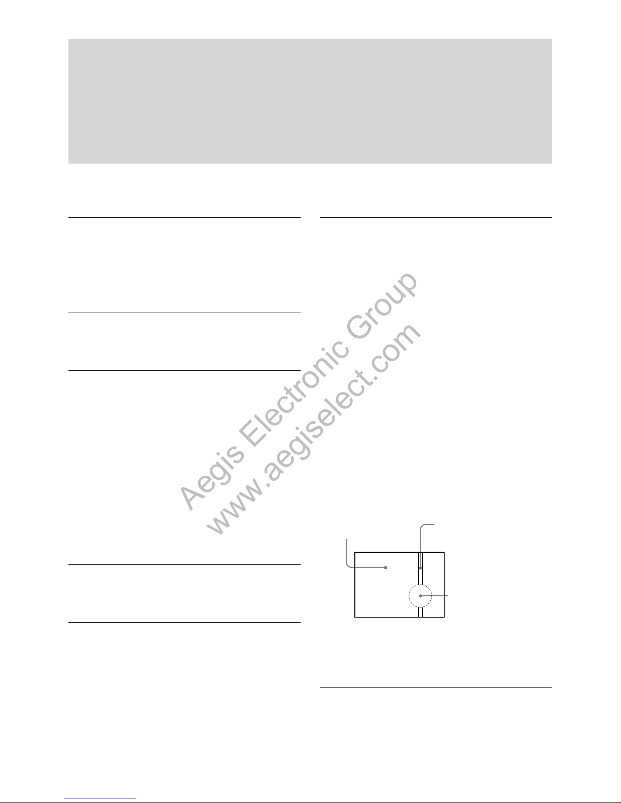
Vertical smear
W
hen an extremely bright object, such as a strong
spotlight or flashlight, is being shot, vertical tails may
be produced on the screen, or the image may be
distorted.
Bright object
(e.g. strong spotlight,
strong reflected light,
flashlight, the sun)
Monitor screen
Vertical tails shown on the
image.
Aliasing
When fine patterns, stripes, or lines are shot, they may
appear jagged or flicker.
Phenomena Specific to Lenses
Ghosting
If a strong light source (e.g., the sun) exists near the
incidence angle of the lens, bright spots may appear in
the image due to diffuse reflection within the lens.
Aegis Electronic Group
www.aegiselect.com
Page 5
5
Locations of Controls
Locations of Controls
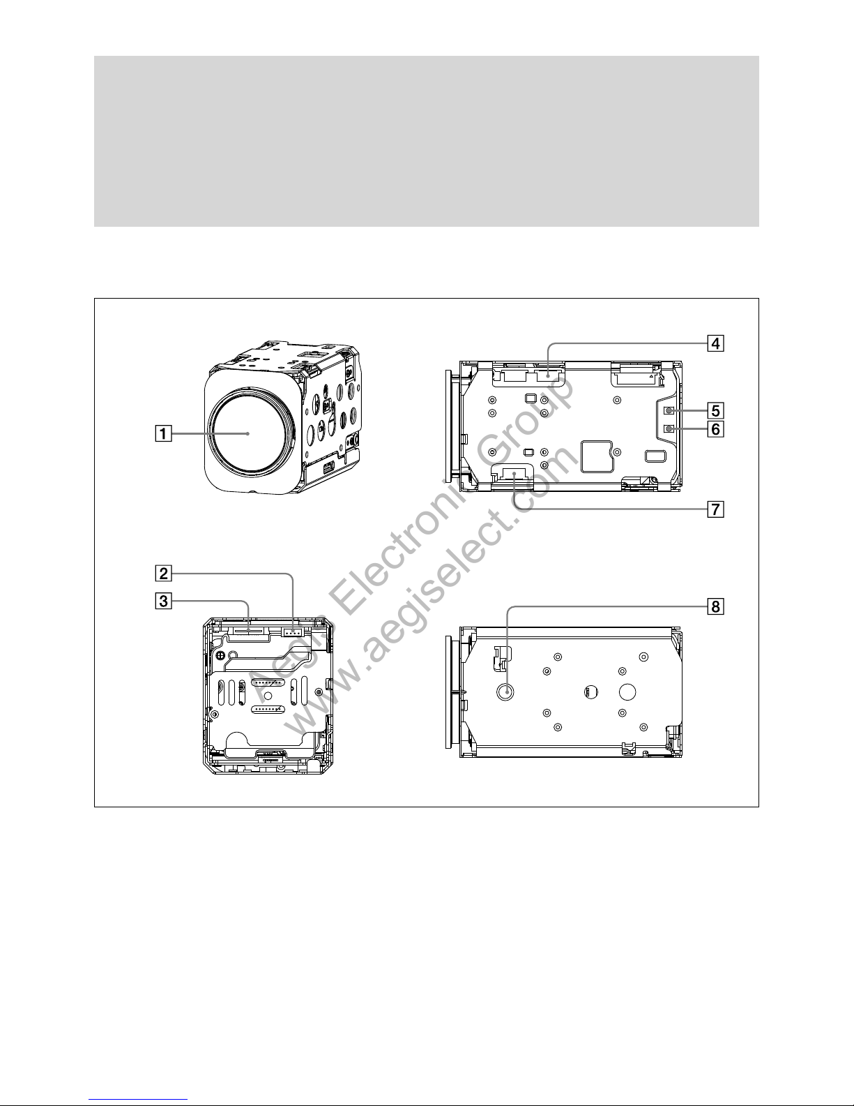
Lens
CN500 jack (f
or Y/C output)
CN501 jack
CN200 jack (f
or digital output)
TELE butt
on
WIDE butt
on
CN702 jack (f
or key SW)
T
ripod screw hole
When a tripod is used, use 7 mm (
9
/32
in.) or less screw to attach it to the
camera. Also, be sure to attach the
tripod securely.
Front
Back
Bottom
Top
Aegis Electronic Group
www.aegiselect.com
Page 6
6
Basic Functions
Basic Functions
Overview of Functions
VISCA commands are the basis of camera control.
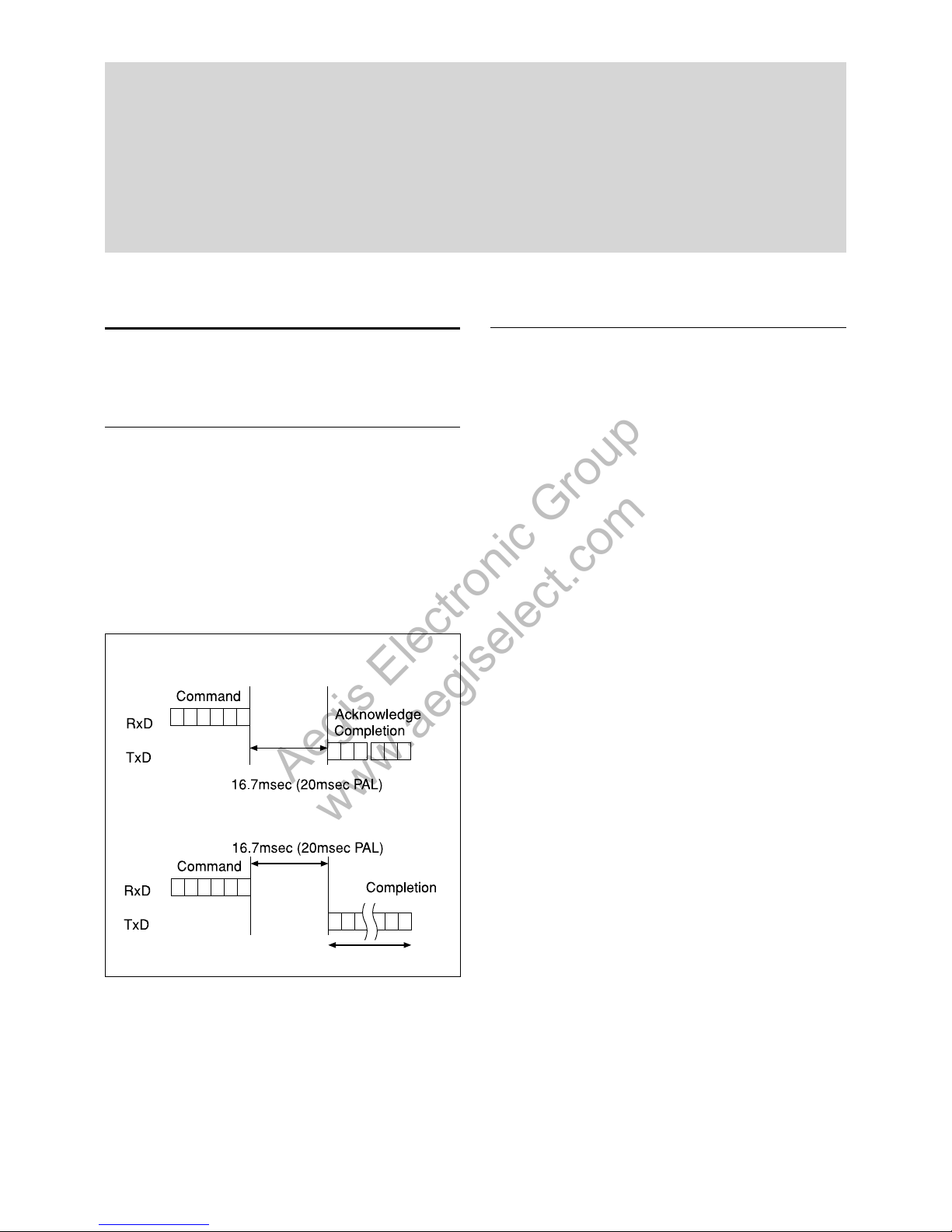
Timing Chart
As VISCA Command processing can only be carried
out one time in a Vertical cycle, it takes the maximum
1V cycle time for an Acknowledge/Completion to be
returned.
If the Command Acknowledge/Completion
communication time can be cut shorter than the 1V
cycle time, then every 1V cycle can receive a
Command.
Query Commands
General Commands
16 Byte
Within
Within
In general
Power On/Off
Powers the camera on and off. When the power is off,
the camera is able to accept only the lowest level of
VISCA Commands; the display and other features are
turned off.
I/F Clear
Clears the Command buffer of the FCB camera.
Clearing the buffer can also be carried out from the
control application software when the power is on.
Address Set
VISCA is a protocol, which normally supports a daisy
chain of up to seven connected cameras via RS-232C
interface. In such cases, the address set command can
be used to assign addresses from 1 to 7 to each of the
seven cameras, allowing you to control the seven
cameras with the same personal computer.
Although the FCB camera does not support direct
connection of cameras in a daisy chain, be sure to use
the address set command to set the address whenever
a camera is connected for the first time.
ID Write
Sets the camera ID.
Mute
Blanks the screen and sends out a synchronizing
signal.
Lens Initialize
Initializes the zoom and focus of the lens. Even when
power is already on, it initializes the zoom and the
focus.
Comp Scan
Blemish compensation of CCD is performed. Even
when power is onm it performs blemish
compensation of CCD.
Aegis Electronic Group
www.aegiselect.com
Page 7

7
Basic Functions
Zoom
The FCB camera employs a 40× optical zoom lens
combined with a digital zoom function; this camera
allows you to zoom up to 480×.
Optical 40×, f = 3.06 mm to 122.4 mm (F 1.6 to F 4.6)
The horizontal angle of view is approximately 60
degrees (wide end) to 1.6 degrees (tele end).
Digital Zoom enlarges the center of the subject by
expanding each image in both the vertical and
horizontal directions. When 480
×
zoom is used, the
number of effective picture elements in each direction
reduces to
1
/12 and the overall resolution deteriorates.
You can activate the zoom in the following three ways.
By pressing the TELE or WIDE buttons on the
camera itself
Using a VISCA Command
Using Standard Mode
Using Variable Mode
There are eight levels of zoom speed.
Direct Mode
Setting the zoom position enables quick movement
to the designated position.
Digital Zoom ON/OFF
In these standard and variable Speed Modes, it is necessary to
send Stop Command to stop the zoom operation.
The Zoom Mode supports a Combined Mode and a
Separate Mode.
Combined Mode
This is the previously existing zoom method. After
the optical zoom has reached its maximum level,
the camera switches to Digital Zoom Mode.
Separate Mode
In this mode, Optical Zoom and Digital Zoom can
be operated separately. You can use digital zoom
magnification at any time from within any level of
optical magnification.
About Continues Zoom position Reply
With ZoomDirect mode, or when zooming
according to a preset, the camera outputs zoom
position data when Continues Zoom position
Reply is set to ON via a command.
Continues Zoom position Reply: y0 07 04 69 0p 0p
0q 0q 0q 0q FF
pp: D-Zoom position
qqqq: Zoom position
Using an external key switch board connected to the
jack for the key SW.
Focus
Focus has the following modes, all of which can be set
using VISCA Commands.
Auto Focus Mode
The Auto Focus (AF) function automatically adjusts
the focus position to maximise the high frequency
content of the picture in a center measurement area,
taking into consideration the high luminance and
strong contrast components.
- Normal AF Mode
This is the normal mode for AF operations.
- Interval AF Mode
The mode used for AF movements carried out at
particular intervals. The time intervals for AF
movements and for the timing of the stops can be
set in one-second increments using the Set Time
Command. The initial value for both is set to five
seconds.
-
Zoom Trigger Mode
When the zoom is changed with the TELE or the
WIDE buttons, the pre-set value (initially set at 5
seconds) becomes that for AF Mode. Then, it
stops.
AF
sensitivity can be set to either Normal or LOW.
- Normal
Reaches the highest focus speed quickly. Use this
when shooting a subject that moves frequently.
Usually, this is the most appropriate mode.
- LOW
Improves the stability of the focus. When the
lighting level is low, the AF function does not take
effect, even though the brightness varies,
contributing to a stable image.
Manual Focus Mode
Manual Focus has both a Standard Speed Mode and a
Variable Speed Mode. Standard Speed Mode focuses
at a fixed rate of speed. Variable Speed Mode has eight
speed levels that can be set using a VISCA Command.
In these standard and variable Speed Modes, it is necessary to send
Stop Command to stop the zoom operation.
One Push Trigger Mode
When a Trigger Command is sent, the lens moves to
adjust the focus for the subject. The focus lens then
holds that position until the next Trigger Command is
input.
Near Limit Setting Mode
Can be set in a range from 1000 (∞)
to C000 (10
mm).
Aegis Electronic Group
www.aegiselect.com
Page 8
8
Basic Functions
White Balance
White Balance has the following modes, all of which
can be set using VISCA Commands.
Auto White Balance
This mode computes the white balance value output
using color information from the entire screen. It
outputs the proper value using the color temperature
radiating from a black subject based on a range of
values from 3000 to 7500K.
This mode is the factory setting.
ATW
Auto Tracing White balance (2000 to 10000K)
Indoor
3200K Base Mode
Outdoor
5800K Base Mode
One Push WB
The One Push White Balance mode is a fixed white
balance mode that may be automatically readjusted
only at the request of the user (One Push Trigger),
assuming that a white subject, in correct lighting
conditions, and occupying more than 1/2 of the
image, is submitted to the camera.
One Push White Balance data is lost when the power
is turned off. If the power is turned off, reset One
Push White Balance.
Manual WB
Manual control of R and B gain, 256 steps each
Outdoor Auto
This is an auto white balance mode specifically for
outdoors. It allows you to capture images with natural
white balance in the morning and evening.
Sodium Vapor Lamp Auto
This is an auto white balance mode that is compatible
with sodium vapor lamps.
Sodium Vapor Lamp
This is a fixed white balance mode specifically for
sodium vapor lamps.
Automatic Exposure Mode
A variety of AE functions are available for optimal
output of subjects in lighting conditions that range
from low to high.
Full Auto
Iris, Gain and Shutter Speed can be adjusted
automatically.
Gain Limit Setting
The gain limit can be set at the Full Auto, Shutter
Priority, Iris Priority, Bright, Spot Exposure and
Manual in the AE mode. Use this setting when image
signal-to-noise ratio is particularly important.
Shutter Priority
1)
Variable Shutter Speed, Auto Iris and Gain
(1/1 to 1/10,000 sec., 16 high-speed shutter speeds
plus 6 low-speed shutter speeds)
1) Flicker can be eliminated by setting shutter to
1/100s for NTSC models used in countries with a 50 Hz
power supply frequency
1/120s for PAL models used in countries with a 60 Hz
power supply frequency
Iris Priority
Variable Iris (F1.6 to Close, 18 steps), Auto Gain and
Shutter speed
Manual
Variable Shutter, Iris and Gain
Bright
Variable Iris and Gain (Close to F1.6, 17 steps and
F1.6 at 15 steps)
AE – Shutter priority
Th
e shutter speed can be set freely by the user to a total
of 22 steps –
16 high speeds and 6 low speeds. When
the slow shutter is set, the speed can be
1
/30s,
1
/15s, 1/8s, 1/4s, 1/2s, 1/1s. The picture output is read at a
normal rate from the memory. The memory is updated
at a low rate from the CCD. AF capability is low. The
displayed number of frame is decreases.
In high speed mode, the shutter speed can be set up to
1/10,000s. The iris and gain are set automatically,
according to the brightness of the subject.
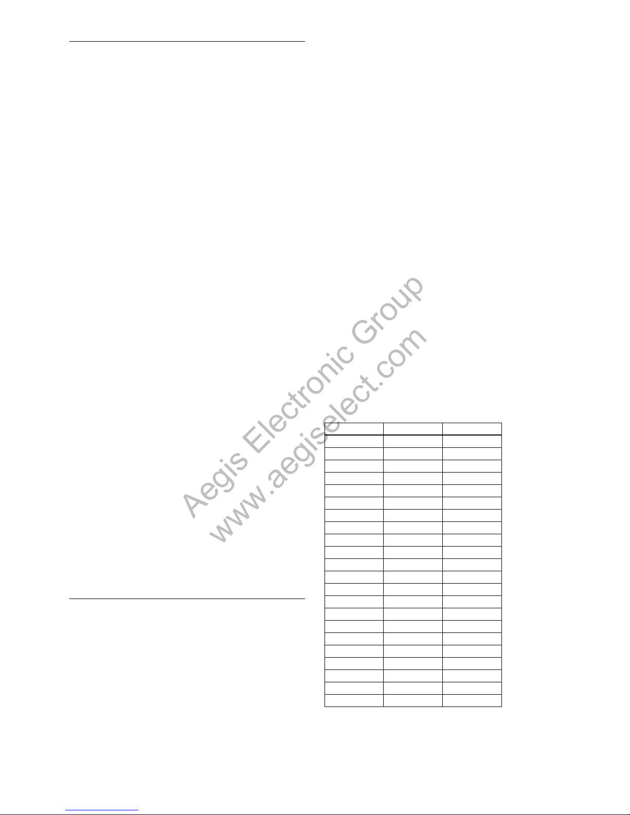
Data NTSC (s) PAL (s)
15 1/10000 1/10000
14 1/6000 1/6000
13 1/4000 1/3500
12 1/3000 1/2500
11 1/2000 1/1750
10 1/1500 1/1250
0F 1/1000 1/1000
0E 1/725 1/600
0D 1/500 1/425
0C 1/350 1/300
0B 1/250 1/215
0A 1/180 1/150
09 1/125 1/120
08 1/100 1/100
07 1/90 1/75
06 1/60 1/50
05 1/30 1/25
04 1/15 1/12
03 1/8 1/6
02 1/4 1/3
01 1/2 1/2
00 1/1 1/1
Aegis Electronic Group
www.aegiselect.com
Page 9
9
Basic Functions
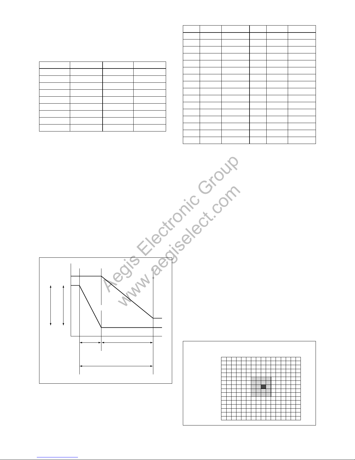
Data Iris Gain Data Iris Gain
1F F1.6 +28
dB 0F F2.4 0 dB
1E F1.6 +26
dB 0E F2.8 0 dB
1D F1.6 +24
dB 0D F3.4 0 dB
1C F1.6 +22
dB 0C F4 0 dB
1B F1.6 +20
dB 0B F4.8 0 dB
1A F1.6 +18
dB 0A F5.6 0 dB
19 F1.6 +16
dB 09 F6.8 0 dB
18 F1.6 +14
dB 08 F8 0 dB
17 F1.6 +12
dB 07 F9.6 0 dB
16 F1.6 +10
dB 06 F11 0 dB
15 F1.6 +8
dB 05 F14 0 dB
14 F1.6 +6
dB 04 F16 0 dB
13 F1.6 +4
dB 03 F19 0 dB
12 F1.6 +2
dB 02 F22 0 dB
11 F1.6 0
dB 01 F28 0 dB
10 F2 0
dB 00 CLOSE 0 dB
When switching from the Shutter Priority mode to the
Bright mode, the shutter speed set in the Shutter
Priority mode is maintained.
Spot Exposure Mode
I
n Full Auto AE, the level for the entire screen is
computed and the optimum Auto Iris and Gain levels
are determined. In Spot AE, a particular section of the
subject can be designated, and then that portion of the
image can be weighted and a value computed so that
Iris and Gain can be optimized to obtain an image.
For example, in an image with a lot of movement and
with varying levels of brightness, portions without
much change can be designated as such a “spot,” and
changes to the screen can be minimized in that area.
As shown in the diagram below, a range of 16 blocks
vertically and 16 blocks horizontally can be designated.
In the case where the center is designated (shown in
black), the level is computed along with a weighted
value for the surrounding block (shaded), including the
specified portions; and then the Gain and Iris are set.
The value of the designated portions and the
surrounding areas should be calculated as 100%, the
rest should be set to 20%. The range of the Spot AE
frame is fixed to 5 blocks vertically and 4 blocks
horizontally.
(8,8)
Horizontal 16
Vertical 16
0
0
1
2
3
4
5
6
7
8
9
A
B
C
D
E
F
1 2 3 4 5 6 7 8 9 A B C D E F
AE – Iris priority
The iris can be set freely by the user to 18 steps
between F1.6 and Close.
The gain and shutter speed are set automatically,
according to the brightness of the subject.
Data Setting value Data Setting value
11 F1.6 08 F8
10 F2 07 F9.6
0F F2.4 06 F11
0E F2.8 05 F14
0D F3.4 04 F16
0C F4 03 F19
0B F4.8 02 F22
0A F5.6 01 F28
09 F6.8 00 CLOSE
AE – Manual
The shutter speed (22 steps), iris (18 steps) and gain
(16 steps) can be set freely by the user.
AE – Bright
Th
e bright control function adjusts both gain and iris
using an internal algorithm, according to a brightness
level freely set by the user. Exposure is controlled by
gain when dark, and by iris when bright.
As both gain and iris are fixed, this mode is used when
exposing at a fixed camera sensitivity. When switching
from Full Auto or Shutter Priority Mode to Bright
Mode, the current status will be retained for a short
period of time.
Only when the AE mode is set to “Full Auto” or
“Shutter Priority,” you can switch it to “Bright.”
MIN
MAX
AGC
CLOSE
OPEN
IRIS
Gain
Dark Bright
IRIS curve
Gain curve
Controlled
by gain
Controlled by IRIS
Bright limit which controllable
for this unit
Aegis Electronic Group
www.aegiselect.com
Page 10
10
Basic Functions
Exposure Compensation
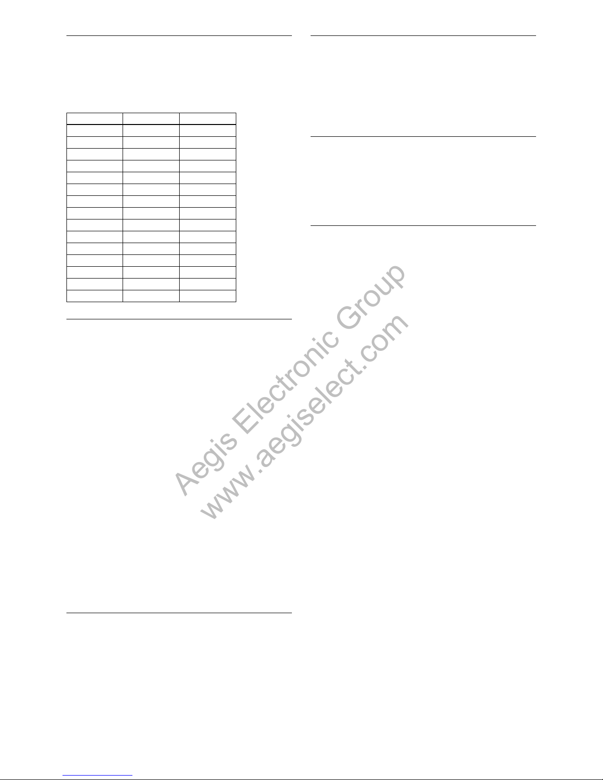
Exposure compensation is a function which offsets the
internal reference brightness level used in the AE
mode, by steps of 1.5 dB.
The reference brightness is 0.
Data Step Setting value
0E +7 +10.5
dB
0D +6 +9
dB
0C +5 +7.5
dB
0B +4 +6
dB
0A +3 +4.5
dB
09 +2 +3
dB
08 +1 +1.5
dB
07 0 0
dB
06 –1 –1.5
dB
05 –2 –3
dB
04 –3 –4.5
dB
03 –4 –6
dB
02 –5 –7.5
dB
01 –6 –9
dB
00 –7 –10.5
dB
Slow AE (Automatic Exposure)
The slow AE Response (automatic exposure) function
allows you to reduce the exposure response speed.
Usually the camera is set up so that the optimum
exposure can be obtained automatically within about 1
second. However, using the slow AE response function
allows you to lengthen the automatic exposure
response speed from the factory setup speed (01 (hex)
up to approx. two minutes (30 (hex)).
For example, with the normal setting (about 1 second),
if the headlights of a car are caught by the camera, the
camera automatically adjusts the exposure so that it can
shoot a high-intensity subject (in this case, the
headlights). As a result, images around the headlights,
that is, the rest of the subject, except the headlights,
becomes relatively dark, and poorly distinguished.
However, using the slow AE function means the AE
response speed will be slower, and response time will
be longer. As a result, even if the camera catches a highintensity subject (e.g., the headlights) for a moment,
you can still easily distinguish the portions of the image
surrounding the headlights.
High Resolution Mode (Default)
A newly developed ISP function enables the filtering of
signals. This allows the camera to provide images with
a high resolution.
Aperture Control
Aperture control is a function which adjusts the
enhancement of the edges of objects in the picture.
There are 16 levels of adjustment, starting from “no
enhancement.” When shooting text, this control may
help by making them sharper.
Back Light Compensation
When the background of the subject is too bright, or
when the subject is too dark due to shooting in the AE
mode, back light compensation will make the subject
appear clearer.
Wide Dynamic Range Mode (WD)
The Wide Dynamic Range mode is a function for
dividing an image into several blocks and correcting
blocked-up shadows and blown-out highlights in
accordance with the intensity difference. It enables you
to obtain images in which portions ranging from dark
to light can be recognized, even when capturing a
subject with a large intensity difference that is backlit
or includes extremely light portions.
A CCD for shooting a wide dynamic range is
employed, and a newly developed image signal
processor combines a long exposure signal (normal
shutter) and a signal of the high intensity portions
obtained by a short exposure (high-speed shutter) to
achieve images with a wide dynamic range.
The Wide Dynamic Range mode includes the following
operation modes.
WD Mode
According to the intensity difference, the long
exposure and short exposure are automatically
adjusted, and the contrast is automatically adjusted by
VE.
Exposure Ratio Mode
The shutter speed ratio between the long exposure
and short exposure is fixed by performing only the
long exposure control. The short exposure is set by
the exposure ratio with respect to the long exposure,
and the contrast is automatically adjusted by VE.
VE (Visibility Enhancer) Mode
This mode automatically adjusts the brightness and
contrast of the dark portion and bright portion of a
single image without combining two images.
Aegis Electronic Group
www.aegiselect.com
Page 11
11
Basic Functions
Noise Reduction
The NR (Noise Reduction) function removes noise
(both random and non-random) to provide clearer
images. By combining 2D filtering according to
brightness and image color, and 3D filtering according
to noise caused by motion and time difference, lowernoise images can be obtained for the corresponding
image brightness of a moving subject.
This function has six steps: levels 1 to 5, plus off.
Level 1 applies to subject motion mainly using 2D filter
effects. With level 5, 2D and 3D filter effects are
maximized, providing the lowest-noise images,
although moving subjects may show trails.
At each level, two filters are set according to noise and
image motion characteristics, so the available level
selections depend on the situation. The default setting
is level 3.
When the wide dynamic range mode (not including VE mode) is ON
in the progressive mode, only the 2D filter operates.
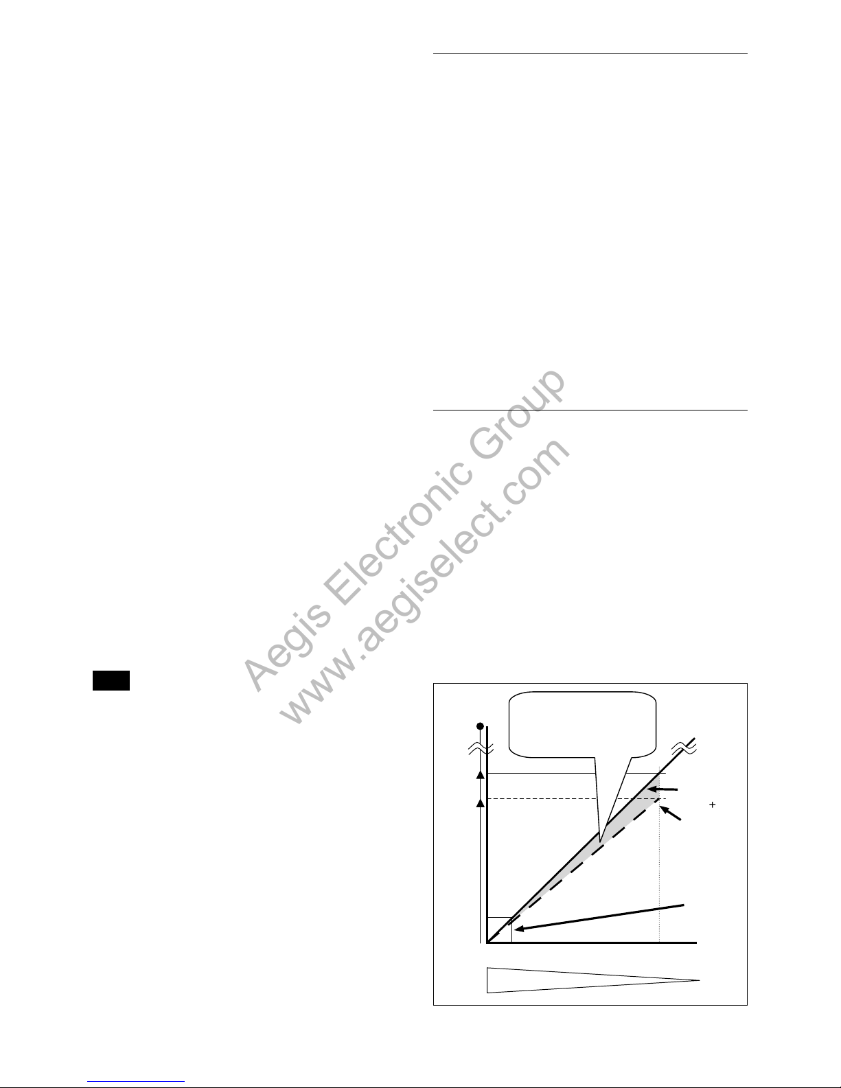
StableZoom™
StableZoom is a function for performing correction
using the Image Stabilizer function in accordance with
the zoom ratio, and smoothly zooming up to
approximately
×44
using a combination of the optical
zoom and digital zoom. The digital zoom can be
further used to zoom up to ×480.
A
t the wide end, you can obtain images without any
reduction in the angle of view and resolution because
the digital zoom is not switched ON. On the other
hand, at the Tele end, the correction effect by the Image
Stabilizer function is at its maximum so blurring is
reduced.
Th
e StableZoom function can be switched ON/OFF in
the register settings.
Blurring is corrected in this
digital zoom area.
x480
approx.
x44
x40
Zoom
ratio
Wide Optical zoom position Tele
Angle of view and resolution
Optical zoom
Digital zoom
StableZoom
The digital
zoom is not
switched ON
at the wide
end.
Supplemental explanation
In the WD mode, there is a restriction as follows.
When 60p/50p is output, the information amount is
equivalent to 30p/25p because the long exposure
signal and short exposure signal are combined.
As for during the VE mode and interlace output, the
information amount will be 60p/50p.
As for the VE mode, the information amount of 60p
can be used because it performs processing with a
single image without a change in the frame rate even
when the progressive mode CCD reading is
performed.
When 30/25 fps is output, the WD mode cannot be ON. Use the VE
mode.
About WD Set Parameter
(Command: 8x 01 04 2D 0p 00 00 00 0t 0u 0v 0w
FF)
p:
Screen display (0: Combined image, 1: Long/short
division, 2: Long-time, 3: Short-time)
Set the screen display to a WD combination image,
long/short exposure division image, long exposure
image, or short exposure image.
tu: Parameter to use in the exposure ratio mode.
Specify the short exposure time by setting the
magnification ratio (×1 to ×128) with regards to a
long exposure time.
v: Maximum gain (0: low 1: middle 2: high)
The gain amount for correcting the blocked-up
shadow is adjusted.
w: 0: low intensity priority 1: balance 2: high
intensity priority
In the low intensity priority, the contrast of dark
portion is emphasized with high priority.
In the high intensity priority, the contrast of bright
portion is emphasized with high priority.
Notes
The following phenomena are unique to the wide dynamic range
m
ode, and are not an indication of camera malfunction.
Solarization may be observed in the images of some subjects.
Since the image is generated by combining the long exposure and
short exposure, noise may appear in the combined area.
Flickering may appear when a flashing light source like
fluorescent lamp is shot.
Aegis Electronic Group
www.aegiselect.com
Page 12
12
Basic Functions
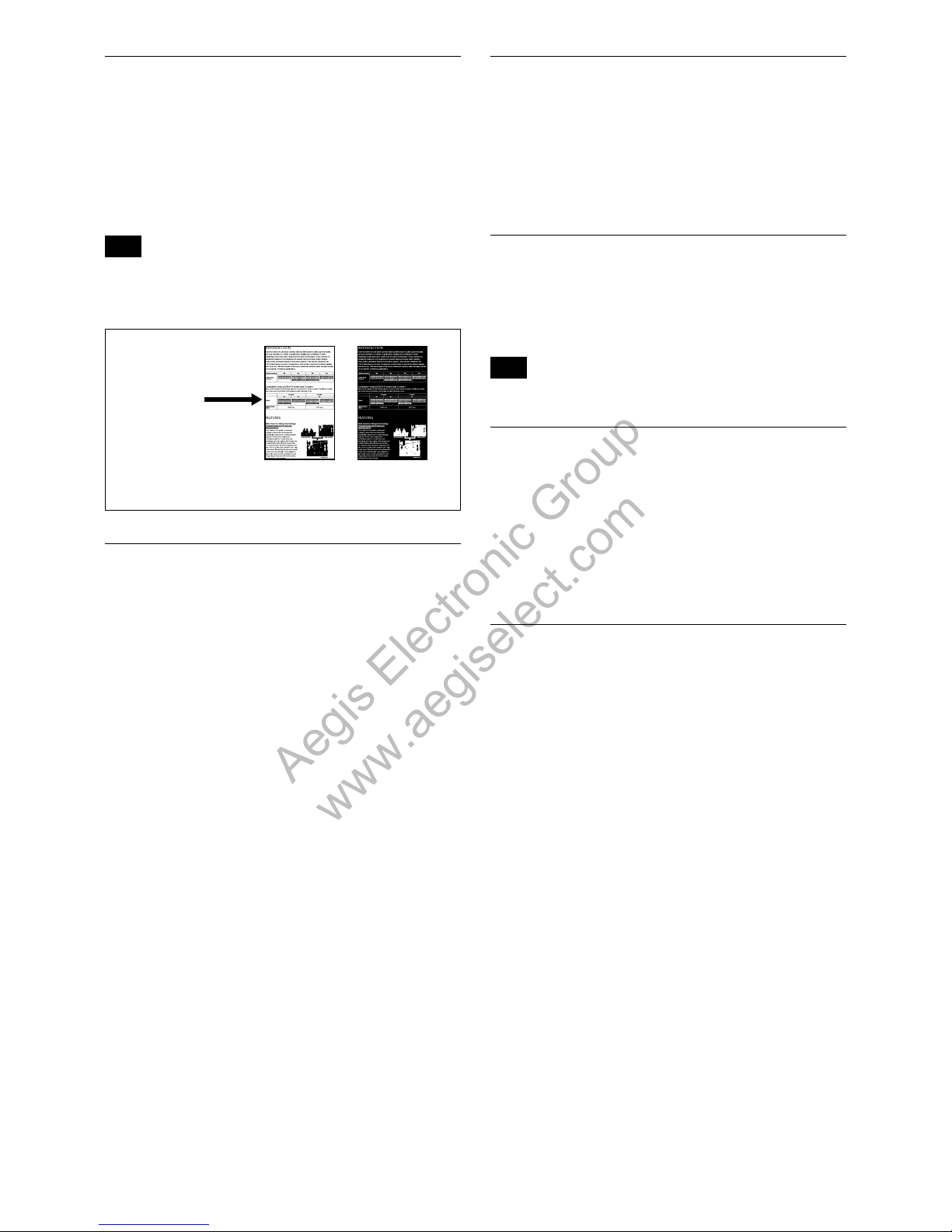
Color Enhancement
A captured color image is converted to 256 levels of
gray, and the binarization process is performed to
convert all gray levels brighter than the threshold value
to white, and all gray levels darker than the threshold
value to black. (Any value can be set for the threshold
level and hysteresis width.) Furthermore, any color can
be assigned to each of the negative and positive.
Note
Flickering in images during color enhancement is not an indication
o
f a camera malfunction. It can be reduced with the threshold level,
hysteresis width, and edge enhancement (aperture) settings.
Grayscale image
(256 levels)
Color image
Binarization
process
Assign any
color
Image Stabilizer
Switching ON the Image Stabilizer function reduces
image blurring caused by, for example, vibration, which
allows you to obtain images without much blurring. A
correction effect of approximately 90% is possible for a
vibration frequency of around 10 Hz.
The Image Stabilizer function employs the digital zoom
system, so the angle of view and resolution are
changed, but the sensitivity is maintained.
Hold Function of Image Stabilizer
W
ith the Image Stabilizer function, suddenly stopping
high-speed movement (pan, tilt, etc.) of the camera
produces a blur sensor counteraction that may cause
image movement. In such a case, you can use a
command setting (hold) to maintain the correction of
the Image Stabilizer function. In this case the image
stabilizer is off, but there is no change in the angle of
view.
Temperature Reading Function
The conversion value (hex) of the temperature sensor
built into to the camera can be read by using a query
command. The conversion value has an error of ±3˚C,
and because the temperature sensor is inside the
camera, this value is not the ambient temperature. Use
it as a reference value.
Slow shutter – Auto/Manual
When set to “Auto,” ensures that the slow shutter is set
automatically when the brightness drops. Effective only
when the AE mode is set to “Full Auto.”
Set to “Slow Shutter Manual” at shipment.
Note
The Slow Shutter Auto function is not available in WD mode.
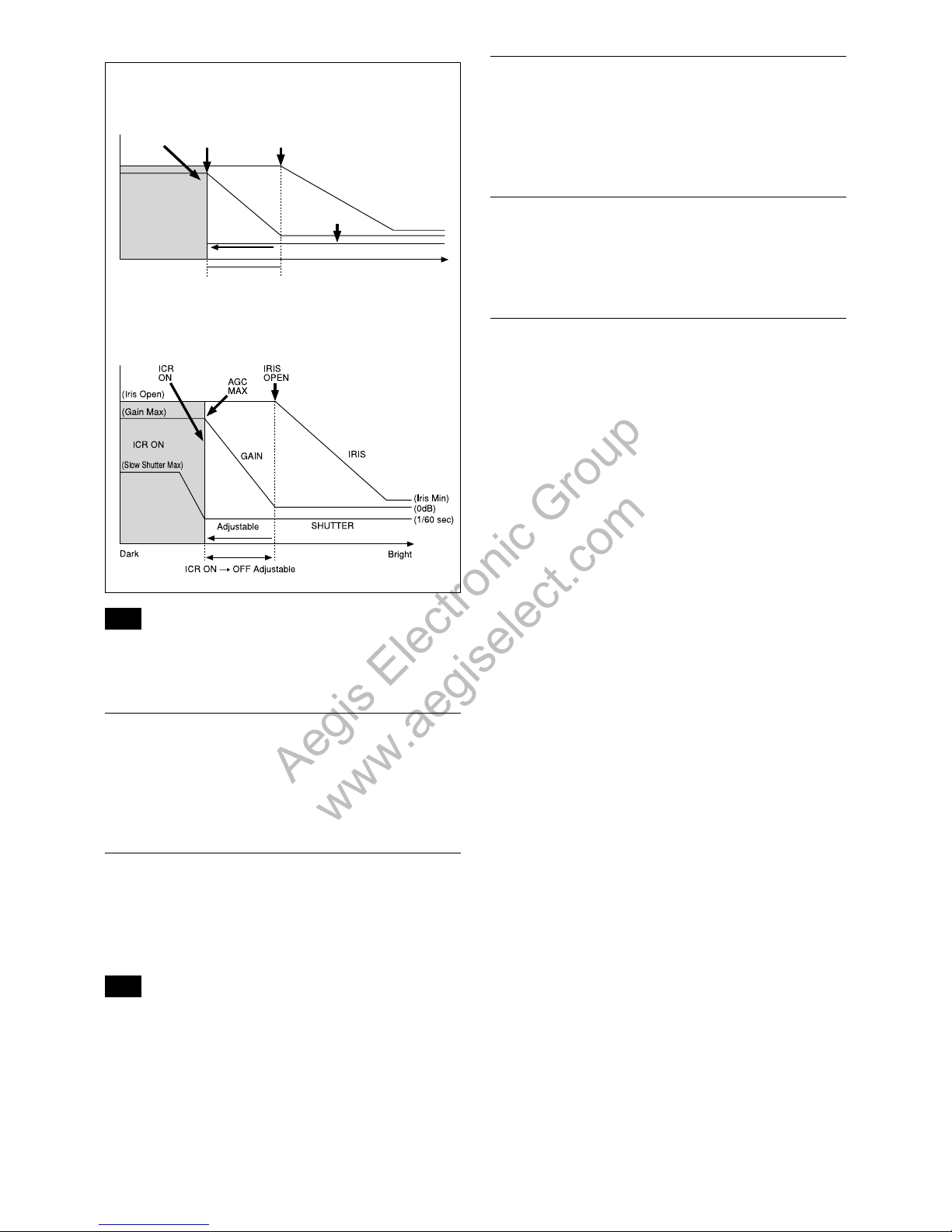
ICR (IR Cut-Removable) Mode
An infrared (IR) Cut-Filter can be disengaged from the
image path for increased sensitivity in low light
environments. The ICR will automatically engage
depending on the ambient light, allowing the camera to
be effective in day/night environments.
When the auto ICR mode is set to ON, the image
becomes black and white.
Auto ICR Mode
Auto ICR Mode automatically switches the settings
needed for attaching or removing the IR Cut Filter.
With a set level of darkness, the IR Cut Filter is
automatically disabled (ICR ON), and the infrared
sensitivity is increased. With a set level of brightness,
the IR Cut Filter is automatically enabled (ICR OFF).
Also, on systems equipped with an IR light, the internal
data of the camera is used to make the proper decisions
to avoid malfunctions.
Auto ICR Mode operates with the AE Full Auto setting.
Aegis Electronic Group
www.aegiselect.com
Page 13
13
Basic Functions
ICR
SHUTTER
Dark Bright
AGC
MAX
IRIS
OPEN
Shutter 1/60 sec
GAIN
ICR ON
IRIS
ICR OFF ON
When Auto Slow Shutter is Off (initial setting)
When Auto Slow Shutter is On
Note
When in Auto_ICR_OFF state and WB data is added (default), a
m
alfunction may occur when the subjects largely consisting of blue
and green colors are taken.
Visibility Enhancer (VE)
Using the Visibility Enhancer function will make the
darker part of a camera image brighter as well as
automatically correct brightness and contrast to show
bright parts clearly without overexposure.
Defog mode
When the surrounding area of the subject is foggy and
low contrast, the defog mode will make the subject
appear clearer by emphasizing the contrast
automatically.
Note
In the defog function, the low contrast is considered to be fog and
co
rrected. Therefore, when a subject such as flat wall is shot, it is
falsely recognized as fog, and the contrast may be emphasized
unnaturally.
Camera ID
The ID can be set up to 65,536 (0000 to FFFF). As this
will be memorized in the nonvolatile memory inside,
data will be saved regardless of whether it has been
backed up.
Effect
It consists of the following functions.
Neg. Art: Negative/Positive Reversal
Black White: Monochrome Image
Others
E-FLIP
This function turns the video output from the camera
upside down.
Mirror Image
Thi
s function reverses the video output from the
camera horizontally.
Freeze
Thi
s function captures an image in the field memory of
the camera so that this image can be output
continuously.
Because communication inside the camera is based on V cycle, the
captured image is always the one 3V to 4V after the sending of a
Command. Thus, you can not specify a time period after sending
EVEN, ODD or a Command.
Memory (Position preset)
Using the position preset function, 6 sets of camera
shooting conditions can be stored and recalled.
This function allows you to achieve the desired status
instantly, even without adjusting the following items
each time.
Zoom Position
Digital Zoom On/Off
Focus Auto/Manual
Focus Position
AE Mode
Shutter control parameters
Bright Control
Iris control parameters
Gain control parameters
Exposure Compensation On/Off
Exposure Level
Backlight Compensation On/Off
Slow Shutter Auto/Manual
White Balance Mode
Aegis Electronic Group
www.aegiselect.com
Page 14
14
Basic Functions
R/B Gain
Aperture Control
ICR Shoot On/Off
WD On/Off
WD Parameter
Defog On/Off
Custom Preset
A
s with the position preset function, the camera
shooting conditions can be stored and recalled. The
settings are recalled when the power is turned on.
For setting items, see the “Initial Settings, Custom Preset and Backup”
section on page 26.
User Memory Area
A user area of 16 bytes allows you to write data, such as
an ID for each customer, data for each system, and so
on, freely.
Note
Rewriting of memory is not unlimited. Be careful to avoid using the
m
emory area for such as unnecessary tasks as rewriting the
contents of the memory for every operation.
Register Setting
The camera’s default settings can be changed by the
register setting command.
Register Setting Command:
8x 01 04 24 mm 0p 0q FF
mm: Register No. (=00 to 7F)
pq: Register Value (=00 to FF)
Register Inquiry Command:
8x 09 04 24 mm FF
mm: Register No.
y0 50 0p 0p FF
pp: Register Value
(returned from the camera)
Example: To set communication speed to 38400 bps
8x 01 04 24 00 00 02 FF
After sending this command, turn power off and
back on (power reset) to resume communication
control at 38400 bps.
Example: Sending to confirm settings
8x 09 04 24 00 FF
y0 50 00 03 FF is returned from the camera
The register setting items and No. are as follows.
Baud Rate: 00
Communication speed can be changed.
OSD Language: 60
OSD Language can be changed.
CCD Scanning Mode: 72
CCD scanning mode can be changed.
Digital Output Mode: 73
The FCB camera supports various output modes.
This register “73” allows changing the output
mode.
For details, see “Register Setting” on page 54.
Zoom Limit: 50 (Wide end), 51 (Tele end)
The Wide and Tele zoom limits can be set.
E-Zoom Max: 52
The maximum digital zoom limit can be specified
(default is
×12).
S
tableZoom: 53
The StableZoom command can be enabled and
disabled with this command.
FocusTrace: 54
When zoom speed is given priority, using the
ZoomDirect command changes focus at high
speed (although the image may be blurred because
focus is not tracked). For example, the focus
transition time from Wide to Tele ends, which
typically takes 2.5 seconds, can be reduced to 1.7
seconds.
FocusOffset: 55
Placing a dome cover in front of the camera may
cause the focal distance of the camera to change.
Especially at the Tele end, this effect exceeds the
AF range, so focus cannot track, although it
responds to changes in this value.
For details, see “Register Setting” on page 54.
Privacy Zone Masking Settings
For details, see page 16.
Motion detection
F
or details, see page 20.
Title Display
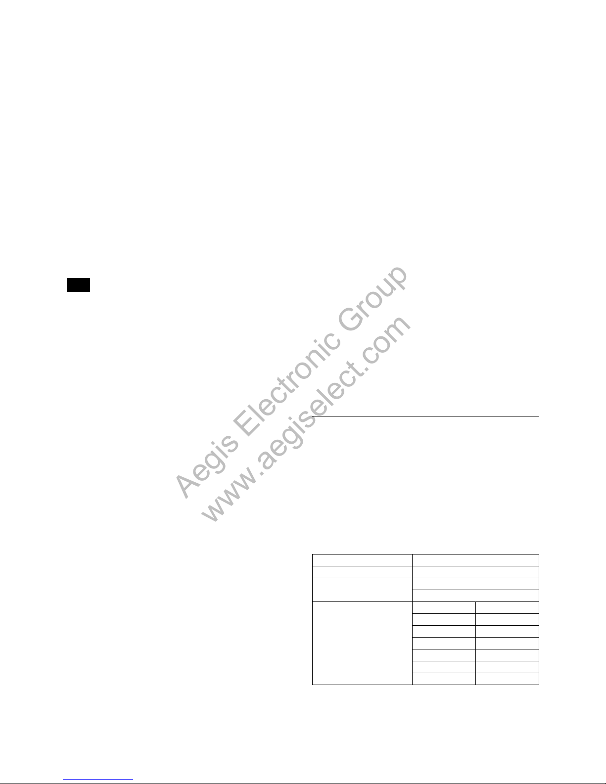
You can set a title composed of up to 11 lines. One
line can contain up to 20 characters.
You can set display on/off, the horizontal position of
the first character, blinking state and color for each
line.
The camera gives priority to lines of a title when the
camera status is displayed on the relevant line. On the
lines where a title is not set, the camera status is
displayed.
Line Number 00 to 0A
H-position 00
to 17
Blink 00:
Does not blink
01: Blinks
Color 00 White
01 Yellow
02 Violet
03 Red
04 Cyan
05 Green
06 Blue
Aegis Electronic Group
www.aegiselect.com
Page 15
15
Basic Functions
Note
Noise may occur when performing phase adjustment with the
L
ine Lock mode, although it should disappear when switching to
Frequency Lock mode for external sync.
Because V-lock synchronization is a simple synchronization method,
color signals like a VBS “Genlock” signal cannot be synchronized.
1)
In V-lock synchronization, the camera makes a V-lock pulse
(VL-PULSE) which synchronizes to the commercial power
supply and uses it as the external synchronization input signal
of the camera, using the fact that the V cycle (59.94 Hz vertical
synchronization signal) and the frequency of the commercial
power supply (60 Hz). The synchronous signal of the camera
will automatically sychronizes to the VL-PULSE in the camera.
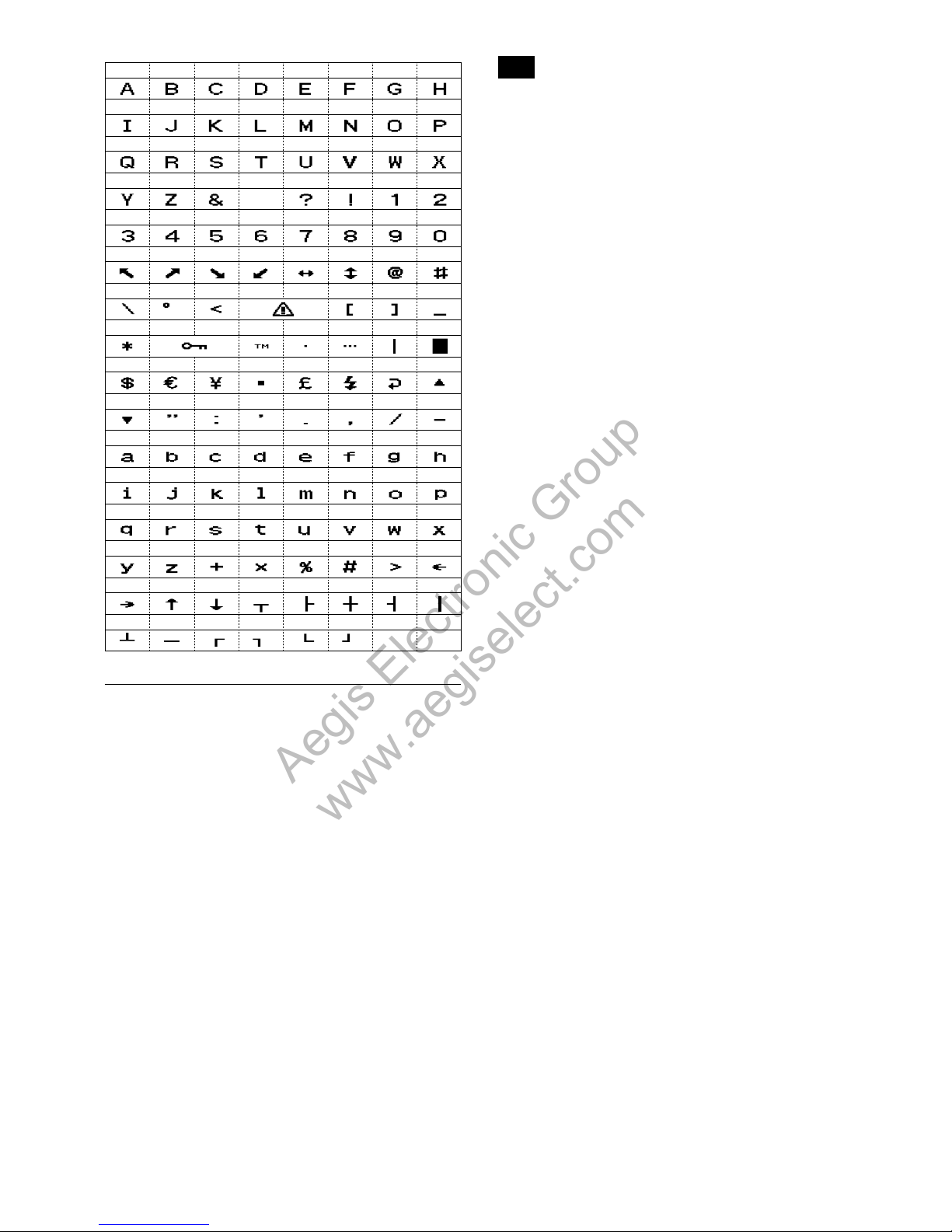
0 01 02 03 04 05 06 07
08 09 0a 0b 0c 0d 0e 0f
10 11 12 13 14 15 16 17
18 19 1a 1b 1c 1d 1e 1f
20 21 22 24 25 26 27
28 29 2a 2b 2c 2d 2e 2f
30 31 32 33 34 35 36 37
38 39 3a 3b 3c 3d 3e 3f
40 41 42 43 44 45 46 47
48 49 4a 4b 4c 4d 4e 4f
50 51 52 53 54 55 56 57
58 59 5a 5b 5c 5d 5e 5f
60 61 62 63 64 65 66 67
68 69 6a 6b 6c 6d 6e 6f
70 71 72 73 74 75 76 77
78 79 7a 7b 7c 7d 7e 7f
23
Synchronization methods
Internal and external synchronization are available;
VISCA Commands allow you to switch between them.
Internal synchronization
An internal vibrator inside the camera generates a
synchronizing signal as a basic oscillator.
NTSC=59.94 Hz
PAL=50 Hz
External synchronization (V-Lock
Synchronization
1)
)
When a TTL level V-Lock pulse is input, the camera
synchronizes to the input signal (V-lock
synchronization). The frequency of the input signal
synchronizes to within
±1H
z of the external
synchronization.
Also, 360 degree phase adjustment is possible due to
the phase adjustment of the V-lock signal.
When adjusting V-Phase, first make the phase
adjustment with the Line Lock mode, then switch to
Frequency Lock mode and enable external sync. If not
performing phase adjustment, switch to Frequency
Lock mode then enable external sync. See “Command
List” on page 31.
Aegis Electronic Group
www.aegiselect.com
Page 16
16
Basic Functions
Privacy Zone Masking Function
Privacy Zone masking protects private objects and areas such as house windows, entrances, and exits which are
within the camera’s range of vision but not subject to surveillance.
Privacy zone masking can be masked on the monitor to protect privacy.
Features
Mask can be set on up to 24 places according to Pan/Tilt positions.
Mask can be displayed on 8 places per screen simultaneously.
Privacy Zones are displayed according to priority in alphabetical order.
Individual on/off zone masking settings.
Selected two colors can be individually set for each of 24 privacy zones.
Interlocking control with zooming.
Interlocking control with Pan/Tilt.
Non-interlocking control with Pan/Tilt.
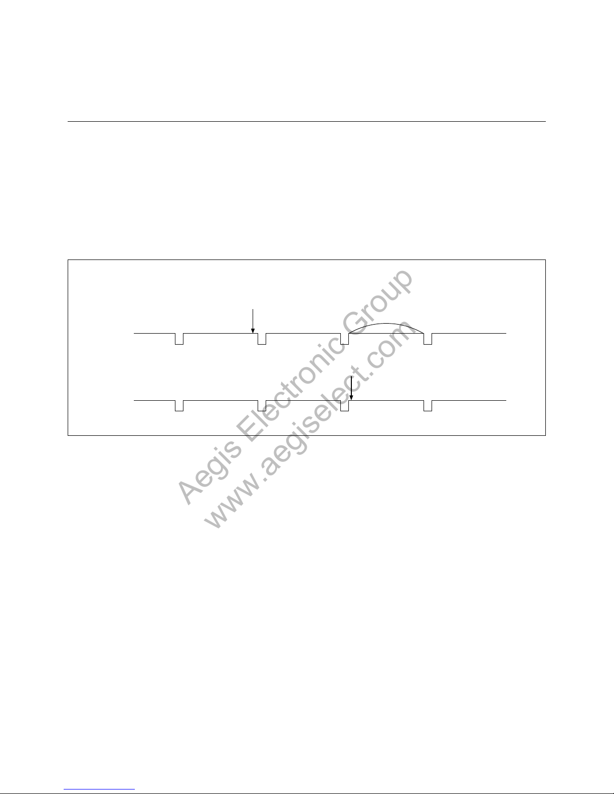
1V
Timing chart
8x 01 .. .. FF
(Mask Setting Command)
Setting command is executed
at this timing.
Aegis Electronic Group
www.aegiselect.com
Page 17
17
Basic Functions
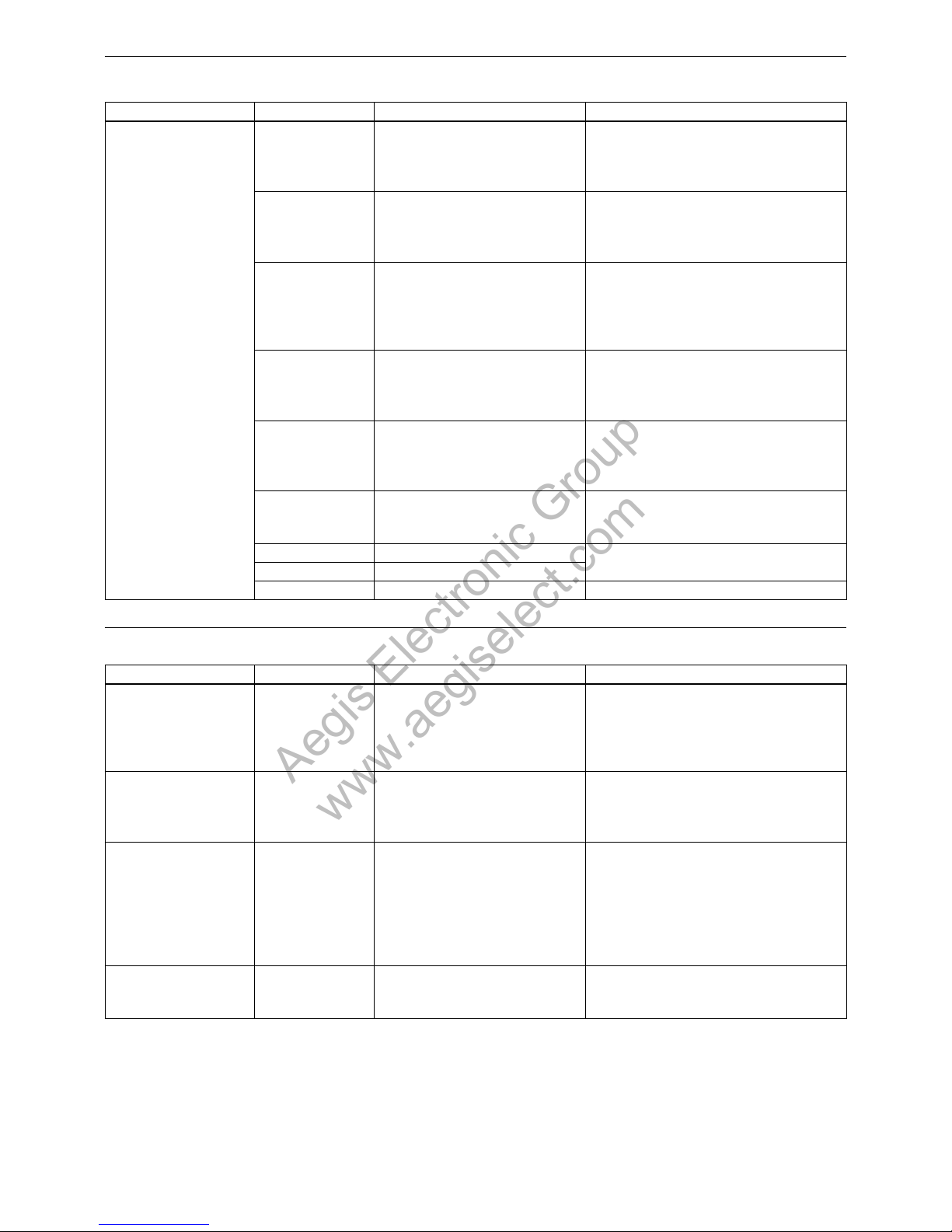
Privacy Zone Setting Command List
Command Set Command Command Packet Comments
CAM_PrivacyZone SetMask 8x
01 04 76 mm nn
0r 0r 0s 0s FF
Setting Mask(Size)
See “mm: Mask setting list”, “nn: Setting”, and
“pp: x, qq:y, rr: w, ss: h” in “Parameters” on
page 18.
Display 8x
01 04 77 pp pp pp pp FF Setting Mask Display On/Off
See “pp pp pp pp: Mask bit” in “Parameters” on
page
18.
p
p pp pp pp: Mask setting (0: OFF, 1: ON)
SetMaskColor 8x
01 04 78 pp pp pp pp qq rr FF Setting Color of Mask
See “pp pp pp pp: Mask bit” and “qq, rr: Color
code” in “Parameters” on page
18.
q
q: Color setting when setting the Mask bit to 0
rr: Color setting when setting the Mask bit to 1
SetPanTiltAngle 8x
01 04 79 0p 0p 0p 0q 0q 0q FF Setting Pan/Tilt Angle
See “Setting pan/tilt angle” in “Parameters” on
page
18.
p
pp: Pan, qqq: Tilt
SetPTZMask 8x
01 04 7B mm 0p 0p 0p
0q 0q 0q 0r 0r 0r 0r FF
Setting the direct position of Pan/Tilt/Zoom
See “mm: Mask setting list” and “Setting pan/tilt
angle” in “Parameters” on page
18.
p
pp: Pan, qqq: Tilt, rrrr: Zoom
Non_InterlockMask 8x
01 04 6F mm
0p 0p 0q 0q 0r 0r 0s 0s FF
Setting non-interlocking the mask to pan/tilt
See “mm: Mask setting list” and “pp:x, qq:y,
r
r:w, ss:h” in “Parameters” on page 18.
Grid On 8x 01 04 7C 02 FF Setting Grid Display On/Off
Grid Off 8x 01 04 7C 03 FF
CenterLineOn 8x
01 04 7C 04 FF Setting the center line On
Privacy Zone Inquiry Command List
Inquiry Command Command Packet Inquiry Packet Comments
CAM_Privacy DisplayInq 8x 09 04 77 FF y0 50 pp pp pp pp FF Inquiry about the status of Setting Mask Display
On/Off
S
ee “pp pp pp pp: Mask bit” in “Parameters” on
page 18.
1:On, 0:Off
CAM_PrivacyPan TiltInq 8x 09 04 79 FF y0 50 0p 0p 0p 0q 0q 0q FF Inquiry about the pan/tilt position currently set
See “Setting pan/tilt angle” in “Parameters” on
page 18.
ppp: Pan, qqq: Tilt
CAM_Privacy PTZInq 8x 09 04 7B mm FF y0 50 0p 0p 0p 0q 0q 0q 0r 0r 0r 0r FF Inquiry about pan/tilt/zoom position at the mm
Mask setting
See “mm: Mask setting list” and “Setting pan/tilt
angle” in “Parameters” on page 18.
ppp: Pan Position,
qqq: Tilt Position
rrrr: Zoom Position
CAM_Privacy MonitorInq 8x 09 04 6F FF y0 50 pp pp pp pp FF Inquiry about the mask currently displayed
See “pp pp pp pp: Mask bit” in “Parameters” on
page 18.
Aegis Electronic Group
www.aegiselect.com
Page 18
18
Basic Functions
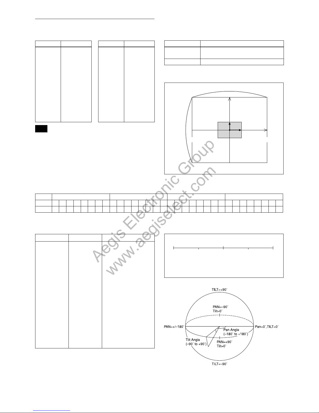
Parameters
mm: Mask setting list
Mask Name mm (Hex) Mask Name mm (Hex)
Mask_A 00h Mask_M 0Ch
Mask_B 01h Mask_N 0Dh
Mask_C 02h Mask_O 0Eh
Mask_D 03h Mask_P 0Fh
Mask_E 04h Mask_Q 10h
Mask_F 05h Mask_R 11h
Mask_G 06h Mask_S 12h
Mask_H 07h Mask_T 13h
Mask_I 08h Mask_U 14h
Mask_J 09h Mask_V 15h
Mask_K 0Ah Mask_W 16h
Mask_L 0Bh Mask_X 17h
Note
The priority order of the mask display is in the sequence from A
(hig
hest) to X (lowest).
When you set the parameters of masks non-interlock, it is
recommended that you set the mask whose priority order is higher,
first.
nn:Setting
nn Setting
00 R
esetting the zone size (the value of w,h) for
the existing mask.
01 S
etting newly the zone size (the value of w,h).
pp: x, qq: y, rr: w, ss: h
Effective display area
160
120
0
h
(x,y)
w
B0h
C4h
3Ch
50h
mask
pp pp pp pp: Mask bit
pp pp pp pp
bit 7 6 5 4 3 2 1 0 7 6 5 4 3 2 1 0 7
6 5 4 3 2 1 0 7 6 5 4 3 2 1 0
Mask - - X W V U T S - - R Q P O N M -
- L K J I H G - - F E D C B A
The “-” must be set to “0”.
qq, rr: Color code
Mask (Color) Code (qq, rr) Semi-transparency (qq, rr)
Black 00h 10h
Gray1 01h 11h
Gray2 02h 12h
Gray3 03h 13h
Gray4 04h 14h
Gray5 05h 15h
Gray6 06h 16h
White 07h 17h
Red 08h 18h
Green 09h 19h
Blue 0Ah 1Ah
Cyan 0Bh 1Bh
Yellow 0Ch 1Ch
Magenta 0Dh 1Dh
Mosaic 7Fh –
Setting pan/tilt angle
Set the angle resolution to 360 (degree)/4096 (1000h).
0 90-180 -90 180
400h800h C00h 800h
Angle/Parameter of Angle (ppp, qqq)
Aegis Electronic Group
www.aegiselect.com
Page 19
19
Basic Functions
Details of Setting Commands
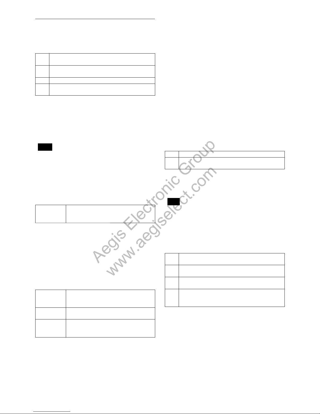
Set Mask
Command:
8x 01 04 76 mm nn 0r 0r 0s 0s FF
Parameter:
mm Setting Mask
See “mm: Mask setting list” in “Parameters” on page 18.
nn S
elects new setting or resetting for the zone.
See “nn: Setting” in “Parameters” on page 18.
rr S
ets the half value “w” of the Mask Width.
ss S
ets the half value “h” of the Mask Height.
See “pp: x, qq: y, rr: w, ss: h” in “Parameters” on page 18.
Comments: To set the mask, first display the object at
the center of the screen. When “nn” is set to 1, the
current Pan/Tilt/Zoom position is recorded in
internal memory.
When “nn” is set to 0, the Pan/Tilt/Zoom position
in memory is not changed.
Notes
The tilt angle at which you can set the mask is between –70 to
+70 degrees.
It is recommended that you set the size to at least twice the size
of the object (height and width).
Set Display
Command:
8x 01 04 77 pp pp pp pp FF
Parameter:
pp pp pp pp Each 24 Privacy Zones corresponds to the BIT.
See “pp pp pp pp: Mask bit” in “Parameters” on
page 18.
Comments: Each of 24 Privacy zones can be switched
on and off individually by a single VISCA
command. If you want to display a Privacy zone,
you must set its bit to 1. If you do not want to
display a Privacy zone, you must set its bit to 0.
Set Mask Color
Command:
8x 01 04 78 pp pp pp pp qq rr FF
Parameter:
pp pp pp pp Each 24 Privacy Zones correspond to the BIT.
See “pp pp pp pp: Mask bit” in “Parameters” on
page 18.
qq S
et the color code include the semi-transparency
code.
rr S
et the color code include the semi-transparency
code. See “qq, rr: Color code” in “Parameters” on
page 18.
Comments: Two different color masks can be chosen.
The colors can be chosen from among 14 colors
including the possibility for semi-transparency of
each color. Therefore two colors from among the
total of 29 colors including mosaic can be
individually set for each of 24 privacy zones.
If the bit of parameter (pp pp pp pp) is set to “0”,
mask color will be “qq” color (Color code). If the
bit of parameter (pp pp pp pp) is set to “1”, the
mask color will be “rr” color (Color code).
Example: 8x 01 04 78 00 00 00 03 10 07 FF
The mask color setting of Mask_A and Mask_B is
White (color code 07h), and the mask color of the
other Mask (C to X) is semi-transparent Black
(color code 10h).
Set Pan/Tilt Angle
Command:
8x 01 04 79 0p 0p 0p 0q 0q 0q FF
Parameter:
ppp Pan Angle
qqq T
ilt Angle
See “Setting pan/tilt angle” in “Parameters” on page 18.
Comments: Pan/Tilt angle settings are hexadecimal
data.
The resolution of Pan/Tilt angle is 0.088 degrees.
Note
When you set the pan/tilt angle, locate the pan/tilt position at the
cen
ter point of the FCB camera’s position.
Set PTZ Mask
Command:
8x 01 04 7B mm 0p 0p 0p 0q 0q 0q 0r 0r
0r 0r FF
Parameter:
mm Setting Mask
See “mm: Mask setting list” in “Parameters” on page 18.
ppp P
an Angle (000 to FFF)
See “Setting pan/tilt angle” in “Parameters” on page 18.
qqq T
ilt Angle (000 to FFF)
See “Setting pan/tilt angle” in “Parameters” on page 18.
rrrr Z
oom Position (000 to 4000)
See “Zoom Ratio and Zoom Position (for reference)” on
page 52.
Comments: Mask can be set at the desired position
by setting the pan tilt angle and zoom position
using a command. The set value can be input by
hexadecimal number.
Aegis Electronic Group
www.aegiselect.com
Page 20
20
Basic Functions
Non Interlock Mask
Command:
8x 01 04 6F mm 0p 0p 0q 0q 0r 0r 0s 0s
FF
Parameter:
mm Setting Mask
See “mm: Mask setting list” in “Parameters” on page 18.
pp S
ets the center position “x” of the Mask on screen.
qq S
ets the center position “y” of the Mask on screen.
rr S
ets the half value “w” of the Mask Width.
ss S
ets the half value “h” of the Mask Height.
See “pp: x, qq: y, rr: w, ss: h” in “Parameters” on page 18.
Comments: Mask does not interlock with pan/tilt.
The limitations of parameters are as follows.
(hexadecimal representation)
x: ±50h
w: ±50h
y: ±3ch
h: ±3ch
Note
When the Set Mask command and the Non Interlock Mask
co
mmand are set to the same mask, the command set later
becomes effective.
Grid
Use the grid displayed on the screen to set mask
positions (see the figure below).
By executing the Center Line On command, only the x
and y axes of the center are displayed. Grids lines
disappear.
14hex (20(10))
14hex (20(10))
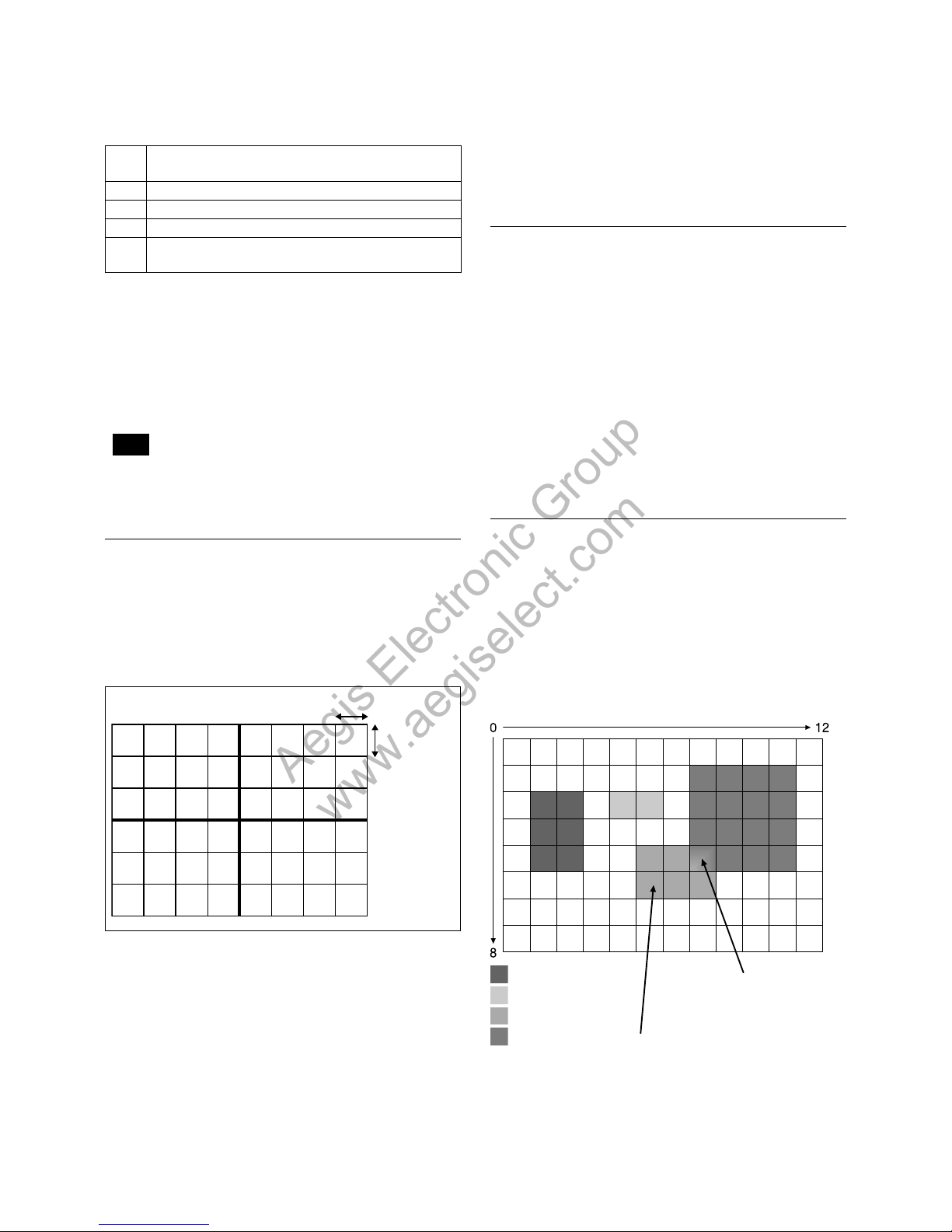
Motion Detection Function
This function instructs the camera to detect movement
within the monitoring area and then send an alarm
signal automatically.
The detected signal goes out through the serial
communication line (VISCA command).
Features
You can set a frame for the detection range of 12
(horizontally) ×
8 (vertically) blocks.
You can set up to four frames.
When the motion is detected in the set frame, the
Alarm Replay VISCA command is sent.
The threshold level for detection can be set (common
to four frames).
The interval of alarm detection can be set up to 256
seconds in units of one second.
You can set on/off for each frame.
The frame number is also sent with Alarm Replay to
report in which frame the motion has been detected.
Frames
Setting frames
You can set the frame by assigning the starting point
and terminating point vertically and horizontally. You
can set up to four frames.
When motion is detected within the range where
frames overlap
Th
e alarms are sent for both frames.
Frame 1
Frame 2
Frame 3
Frame 4
Within this overlapped
range, alarms are sent for
both frame 3 and frame 4.
At this position, the
alarm for frame 3 is sent.
Aegis Electronic Group
www.aegiselect.com
Page 21
21
Basic Functions
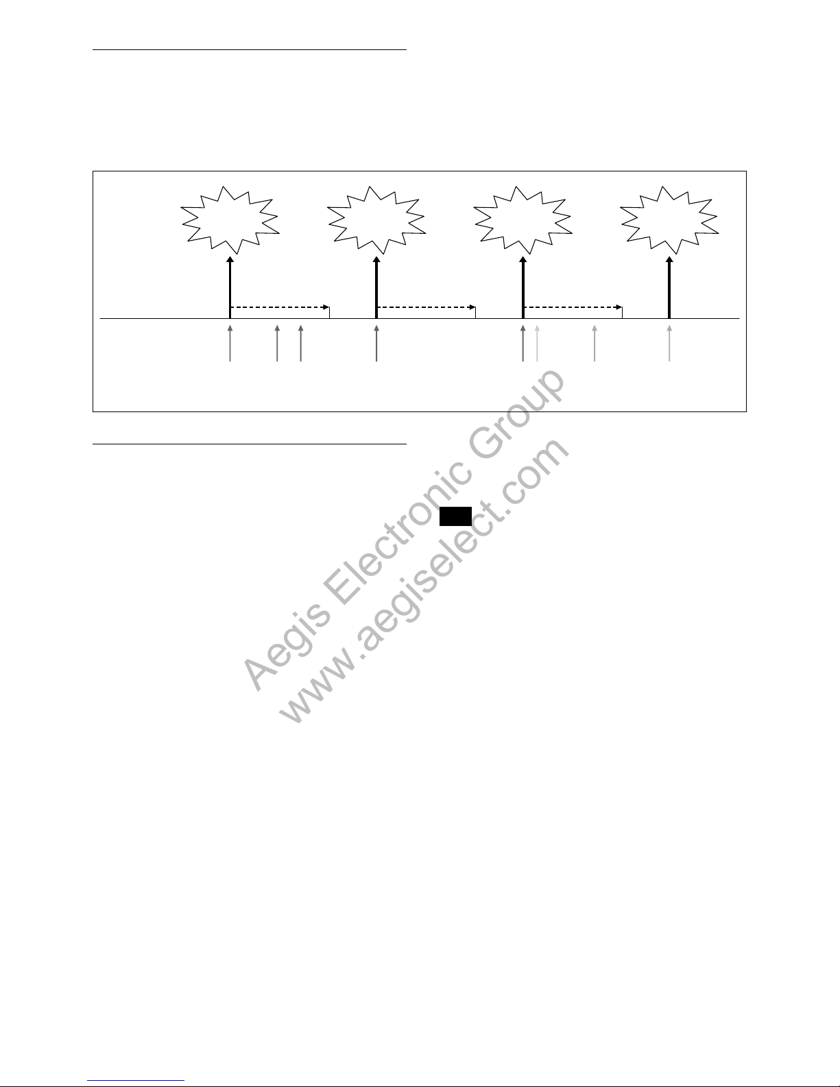
Sending Alarms
When motion is detected, the Alarm Replay
command is issued via the serial command (VISCA)
communication line.
Alarm interval
Alarm issue Alarm issue Alarm issue Alarm issue
Interval Interval Interval
Motion is
detected
in frame 1.
Motion is
detected
in frame 1.
Motion is
detected
in frame 1.
Motion is
detected
in frame 1.
Motion is
detected
in frame 1.
Motion is
detected
in frame 2.
Motion is
detected
in frame 3.
Motion is
detected
in frame 3.
Setting Commands
MD On/Off
The Display mode is set by the Function Set
command and frames are set by the Frame Set
command. By sending an MD On command, the
frame is displayed when motion is detected in the set
frame. The Alarm Reply command is issued via the
serial command (VISCA) communication line.
8x 01 04 1B 02 FF --- On
8x 01 04 1B 03 FF --- Off
Function Set
Select the detected frame, and set the Threshold Level
and the Interval Time.
8x 01 04 1C 0m 0n 0p 0q 0r 0s FF
m: Display Mode on/off (bit0: Frame)
n: Detection Frame set on/off (bit0:Frame0, bit1:
Frame1, bit2:Frame2, bit3:Frame3)
-- (0 to F)
pq: Threshold -- (00 to FF)
rs: Interval time set -- (00 to FF)
* (When pq and rs are 0, the command is received, but
the setting is disabled.)
Frame Set
You can set up to four frames by assigning the starting
and terminating points.
Note
Set a terminating point higher vertically and horizontally than the
s
tarting point. If you set the wrong value, the command yields an
error.
8x 01 04 1D 0m 0p 0q 0r 0s FF
m: Select Detection Frame (0: Frame0, 1: Frame1, 2:
Frame2, 3: Frame3) -- (0, 1, 2, 3)
p: Frame set Start Horizontal Position -- (00 to 0B)
q: Frame set Start Vertical Position -- (00 to 07)
r: Frame set End Horizontal Position -- (01 to 0C)
s: Frame set End Vertical Position -- (01 to 08)
Alarm Reply
When motion is detected in the set frame, the camera
issues this command. This command includes the
information on the number of the detected frame.
y0 07 04 1B 0p FF
p: Frame Number (bit0: Frame0, bit1: Frame1, bit2:
Frame2, bit3: Frame3)
When multiple motions are detected or motion is
detected in another frame within the set interval
following the original time the alarm was issued,
another alarm command is not issued.
When motion is detected after the interval time
elapsed, the alarm is issued again.
Aegis Electronic Group
www.aegiselect.com
Page 22
22
Basic Functions
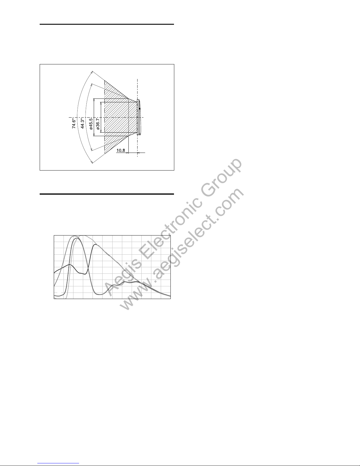
Eclipse
When designing the housing, refer to the dimensional
allowance as shown in the figure below.
Spectral Sensitivity
Characteristics
Relative response [a.u.]
0.0
0.1
0.2
0.3
0.4
0.5
0.6
0.7
0.8
0.9
1.0
400 450 500 550 600 650 700 750 800 850 900 950 1000
WaveLength[nm]
Ye
Mg
Cy
G
Use the graph as a reference value. (We can not
guarantee these values.)
This data is measured when the IR cut filter is removed
and the characteristics of the lens and optical source
characteristics are ignored.
Aegis Electronic Group
www.aegiselect.com
Page 23
23
Basic Functions
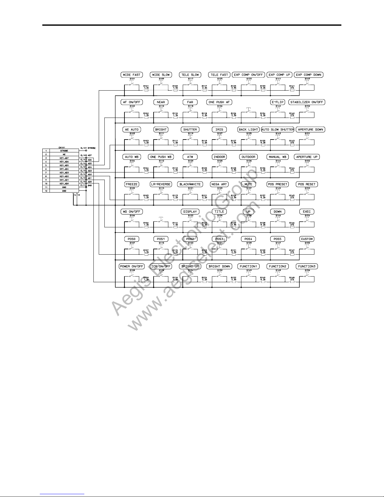
Key Switch Circuitry
The circuitry shown below is an example. Note that all switches in the figure do not function in all models.
For more information, refer to the command list, check functions on the camera, or contact your Sony dealer.
The CN101 is connected to the FCB camera main unit.
Aegis Electronic Group
www.aegiselect.com
Page 24
24
Basic Functions
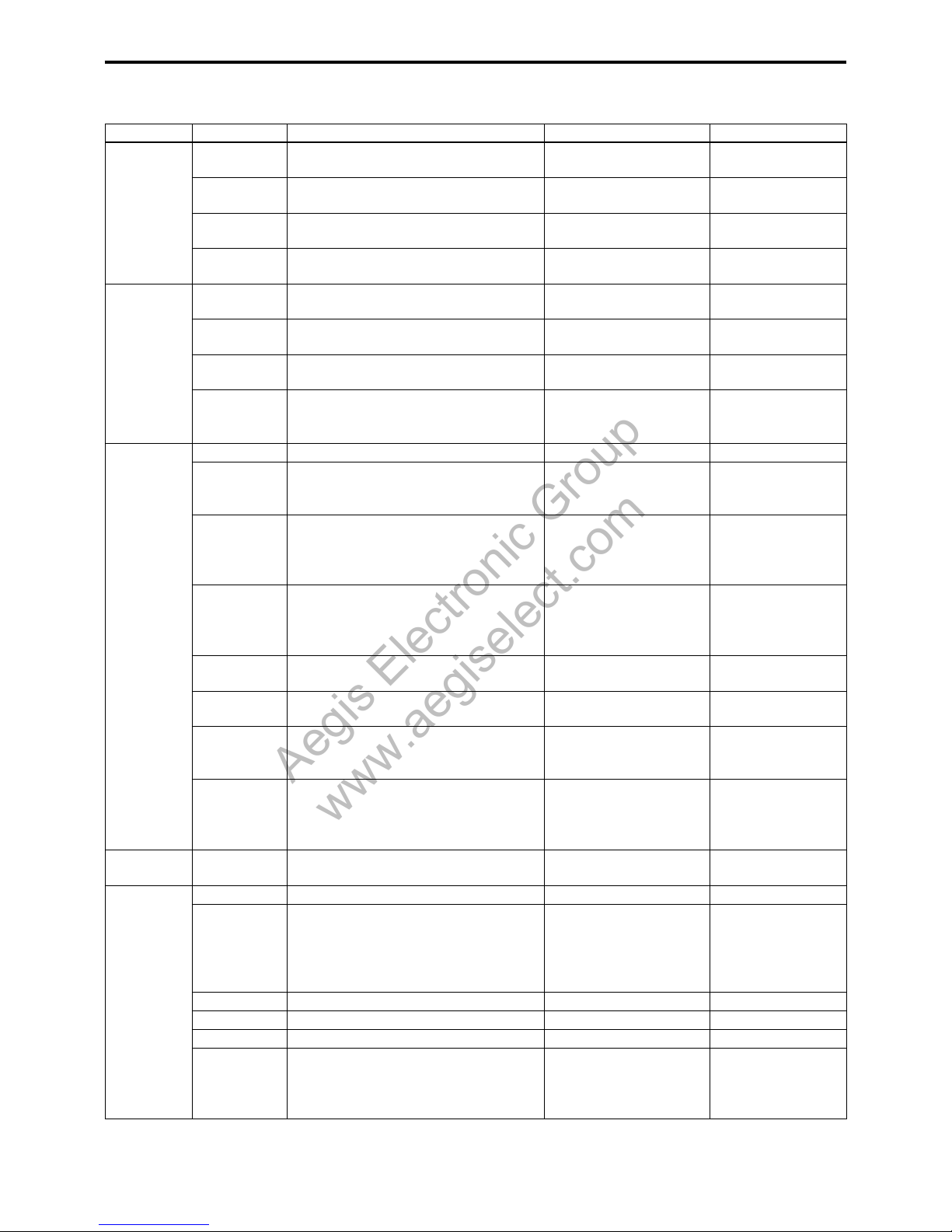
Key Function Specifications
Classification Name Function Button operation Mode display
ZOOM WID
E FAST Move ZOOM to WIDE side quickly. Pressing repeatedly allowed. ZOOM bar displayed
for 3 s.
WIDE SLOW Move ZOOM to WIDE side slowly. Pressing repeatedly allowed. ZOOM bar displayed
for 3 s.
TELE FAST Move ZOOM to TELE side quickly. Pressing repeatedly allowed. ZOOM bar displayed
for 3 s.
TELE SLOW Move ZOOM to TELE side slowly. Pressing repeatedly allowed. ZOOM bar displayed
for 3 s.
FOCUS AF
ON/OFF Switch between Auto Focus and Manual Focus. Switch between Auto and
Manual.
M
anual F indication
NEAR M
ove focus to NEAR side in Manual Focus
mode.
P
ressing repeatedly allowed. Near indication
FAR M
ove focus to FAR side in Manual Focus
mode.
P
ressing repeatedly allowed. Far indication
ONE PUSH AF Perform AF operation once in Manual Focus
mode.
R
equest One Push AF. Manual F indication
flashes while request is
made.
AE AE
AUTO Switch to AE FULL Auto mode. Request AE Full Auto. No display
BRIGHT S
witch to variable brightness mode (BRIGHT),
depending on the conditions for mode shifting.
Request Bright mode.
Pressing Up/Down key
repeatedly allowed.
Bright bar display
SHUTTER S
hutter priority AE mode Request shutter priority AE
mode.
P
ressing Up/Down key
repeatedly allowed.
Shutter code display
IRIS I
ris priority AE mode Request iris priority AE
mode.
P
ressing Up/Down key
repeatedly allowed.
Iris code display
BACK LIGHT Switch backlight on/off in AE FULL Auto
mode.
S
witch on/off. Backlight indication
EXP COMP
ON/OFF
S
witch the exposure compensation function
ON/OFF.
Switch on/off. Exposure compensation
code display
EXP COMP UP Increase the exposure compensation (UP).
(Used during exposure compensation mode.
1.5 dB increments.)
Request UP/pressing
repeatedly allowed.
Exposure compensation
code display
EXP COMP
DOWN
D
ecrease the exposure compensation
(DOWN).
(Used during exposure compensation mode.
1.5 dB increments.)
Request DOWN/pressing
repeatedly allowed.
Exposure compensation
code display
WD WD
ON/OFF Switch the Wide Dynamic Range mode ON/
OFF
S
witch on/off. WDR character display
WB A
UTO WB Switch to AUTO WB mode. Request Auto WB mode. No display
ONE PUSH WB Switch to One Push WB mode when pressed
once and capture data when pressed 2nd time.
Request One Push WB mode
and trigger.
One Push indication
flashes at 0.8 Hz before
capturing data, at 3.2 Hz
during capturing, and
lights after capturing.
ATW S
witch to ATW mode. Request ATW mode. ATW display
INDOOR En
able WB at 3200K in INDOOR mode. Request Indoor mode. Indoor indication
OUTDOOR En
able WB at 5800K in OUTDOOR mode. Request Outdoor mode. Outdoor indication
MANUAL WB Switch to Manual WB mode.
Enable R control when pressed once and
enable B control when pressed 2nd time.
Switchable with UP/DOWN key.
Switch between R control and
B control in manual WB
mode. Pressing Up/Down key
repeatedly allowed.
“WB-MAN”
(character display)
Aegis Electronic Group
www.aegiselect.com
Page 25
25
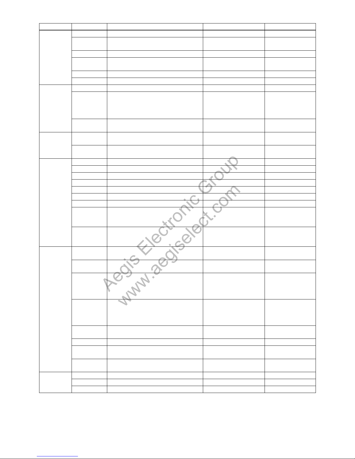
Basic Functions
Classification Name Function Button operation Mode display
FEATURE FREEZE C
apture still image. Switch on/off. CAPTURE indication
LR REVERSE Horizontal reversal Switch on/off. Horizontal reversal
indication
E-FLIP T
urn upside down Switch on/off. Turn upside down mark
BLACK &
WHITE
B
lack-and-white output Switch on/off. B&W display
NEGA ART Negative art output Switch on/off. Neg Art display
MUTE M
uting video output Switch on/off. No display
DISPLAY DISPLAY Display S
witch on/off. Display/no display
TITLE T
itle setting
Request setting. Setting is
started with Exec.
Pressing Up/Down key
repeatedly allowed.
Title setting screen
display
EXEC C
onfirm title setting. Select with Up/Down and
confirm with Exec.
Sets screen selection
and displays it in yellow.
UP/DOWN UP D
ata UP key (priority for AE mode, Bright,
manual WB, title, and clock)
Request UP. Selection highlighted.
reversal
DOWN D
ata DOWN key (priority for AE mode,
Bright, manual WB, title, and clock)
Request DOWN. Selection highlighted.
reversal
PRESET POS0 R
ecall preset position 0. Request recall. RECALL POS0
POS1 R
ecall preset position 1. Request recall. RECALL POS1
POS2 R
ecall preset position 2. Request recall. RECALL POS2
POS3 R
ecall preset position 3. Request recall. RECALL POS3
POS4 R
ecall preset position 4. Request recall. RECALL POS4
POS5 R
ecall preset position 5. Request recall. RECALL POS5
CUSTOM R
ecall custom preset. Request recall. RECALL
POS PRESET Write data.
Enabled when pressed together with POS
button.
R
equest setting. Enabled
when pressed together with
POS key.
PRESET display
POS RESET Delete data.
Enabled when pressed together with POS
button.
R
equest deletion. Enabled
when pressed together with
POS key.
RESET display
Others AP
ERTURE UP Increase aperture (Aperture UP) Request UP. Aperture bar displayed
for 3 s.
APERTURE
DOWN
D
ecrease aperture (Aperture DOWN) Request DOWN. Aperture bar displayed
for 3 s.
BRIGHT UP Raise brightness setting (Bright UP)
(When not in Bright mode, switching to Bright
mode is made automatically depending on the
conditions.)
R
equest UP./Pressing
repeatedly allowed.
Bright bar display
BRIGHT
DOWN
L
ower brightness setting (Bright DOWN)
(When not in Bright mode, switching to Bright
mode is made automatically depending on the
conditions.)
R
equest DOWN./Pressing
repeatedly allowed.
Bright bar display
AUTO SLOW
SHUTTER
S
witch Auto Slow Shutter on/off. Switch on/off. “ASS” (character
display)
ICR ON/OFF Switch ICR mode on/off Switch on/off. ICR indication
STABILIZER
ON/OFF
S
witch the Image Stabilizer function ON/OFF. Switch on/off. Image Stabilizer “OFF”
mark
POWER
ON/OFF
S
witch the POWER (Standby) ON/OFF. Switch on/off. –
FUNCTION FUNCTION1 – – –
FUNCTION2 – – –
FUNCTION3 – – –
Aegis Electronic Group
www.aegiselect.com
Page 26
26
Basic Functions
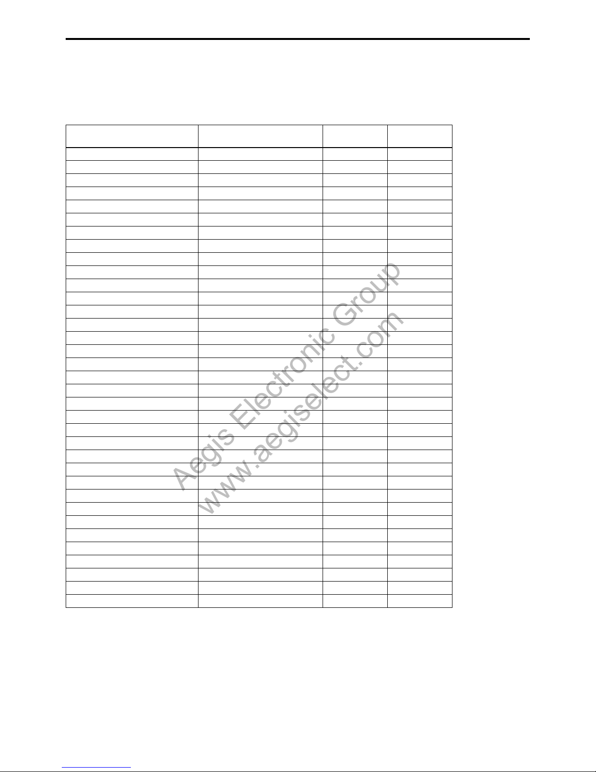
Initial Settings, Custom Preset and Backup
Initial settings for the various functions of the FCB camera are indicated in the “Initial settings” column.
The “Custom preset” column indicates whether the custom preset function can be used to store the settings. The
function enables the stored settings to be recalled automatically when the camera is turned on. The “Back up at
standby” column indicates whether the data is preserved even when the camera is powered OFF.
Mode/Position setting Initial settings
Custom
preset
Back up
at standby
Z
oom Position Wide end
D-Z
oom On/Off On
D-Z
oom Separate/Combine Combine
D-Z
oom Position 00h
F
ocus Position —
F
ocus Auto/Manual Auto
N
ear Limit Setting B000h (30 cm)
AF
Sensitivity Normal
AF
Mode Normal
AF
Run Time 5 sec
AF
Interval 5 sec
WB
Mode Auto
WB
Data (Rgain, Bgain) —
On
e Push WB Data —
AE
Mode Full Auto
AE
Response 01
WD
On/Off Off
S
low Shutter Mode Manual
S
hutter Position 1/60 sec (NTSC), 1/50 sec (PAL)
I
ris Position —
Ga
in Position —
B
right Position —
E
xposure Compensation On/Off Off
E
xposure Compensation Amount ±0
B
ackLight On/Off Off
S
pot AE On/Off Off
S
pot AE Position Setting X=8, Y=8
A
perture Level 6
H
igh Resolution Mode On/Off On
LR
Reverse On/Off Off
F
reeze On/Off Off
P
icture Effect Off
I
CR On/Off Off
A
uto ICR On/Off Off
A
uto ICR Threshold Level 14H
A
circle “”
in this column signifies that the data is preserved.
A cross “”
signifies that the data IS NOT preserved.
Aegis Electronic Group
www.aegiselect.com
Page 27
27
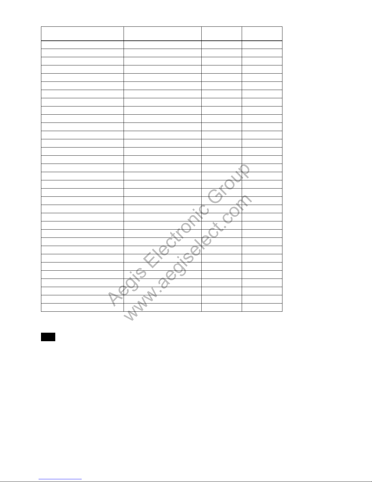
Basic Functions
Mode/Position setting Initial settings
Custom
preset
Back up
at standby
C
amera Memory Same as the initial value setting
Di
splay On/Off Off
M
ute On/Off Off
A
uto ICR Alarm On/Off Off
I
mage Stabilizer On/Off/Hold Off
D
efog On/Off Off
NR
Level 3
Ga
in Limit —
C
olor Enhancement On/Off Off
T
itle Display On/Off Off
T
itle Setting —
M
ask Setting —
M
ask Display On/Off Off
M
ask Color Setting —
G
rid/Center Line Display On/Off Off
A
larm On/Off Off
A
larm Mode —
A
larm Detect Level —
E-Fli
p On/Off Off
P
rivacy Zone On/Off Off
P
rivacy Zone Setting —
K
ey Lock On/Off Off
C
amera ID 0000h
E
xternal Lock Mode Internal
V-Phase
Vsy
nc
edge position
A
larm DayNight Threshold Level —
MD
On/Off Off
MD
Display Setting Off
MD
Threshold Level 10h
MD
Interval 1 sec
MD
Window Setting —
Z
oomPos Continuous Output On/Off Off
Z
oomPos Continuous Output Interval 3Ch
A
circle “”
in this column signifies that the data is preserved.
A cross “”
signifies that the data IS NOT preserved.
Note
The number of times written to EEPROM (when Custom Preset is executed) is limited.
Aegis Electronic Group
www.aegiselect.com
Page 28
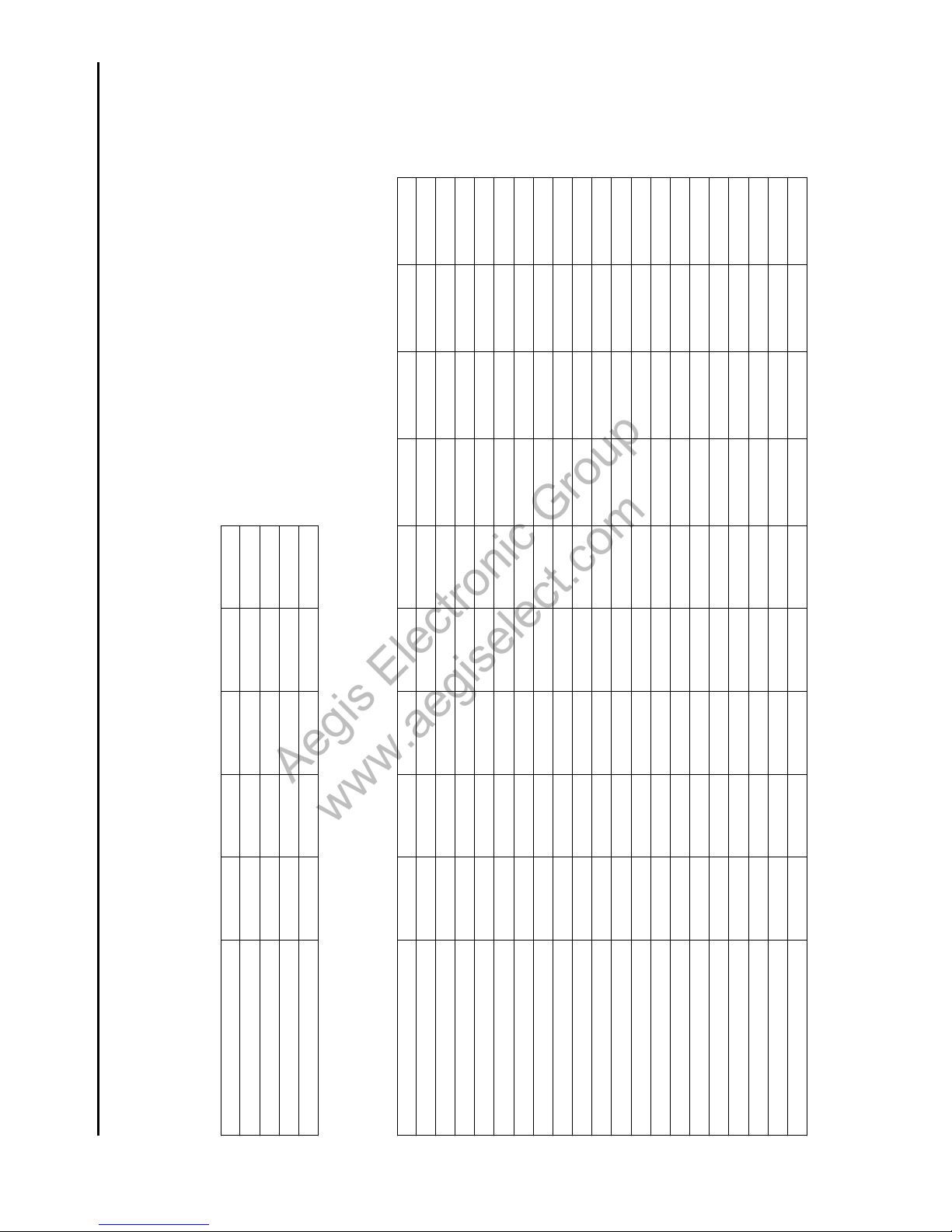
28
Basic Functions
Mode Condition
Condition
Mode Power Off Initializing Power On Freeze On MemRecall
Address Set
IF_Clear
C
ommand Cancel
P
ower On/Off
Lens
Mode Power Off Initializing Power On Freeze On MemRecall Zoom Direct Focus Direct ZmFo Direct Focus Auto
Zoom Tele/Wide/Stop
Z
oom Direct
Z
oom Focus Direct
D-Z
oom On/Off
D-Z
oom Separate/Combine
D-Z
oom Tele/Wide/Stop
D-Z
oom ×1/Max
D-Z
oom Direct
F
ocus Far/Near/Stop
F
ocus Direct
F
ocus Auto/Manual
On
e Push AF
F
ocus Near Limit
AF
Sensitivity Normal/Low
AF
Mode Norm/Interval/Zoom
AF
Activation Time/Interval Setting
C
amera Memory Set/Reset
C
amera Memory Recall
L
ens Initialize
C
omp Scan
Aegis Electronic Group
www.aegiselect.com
Page 29
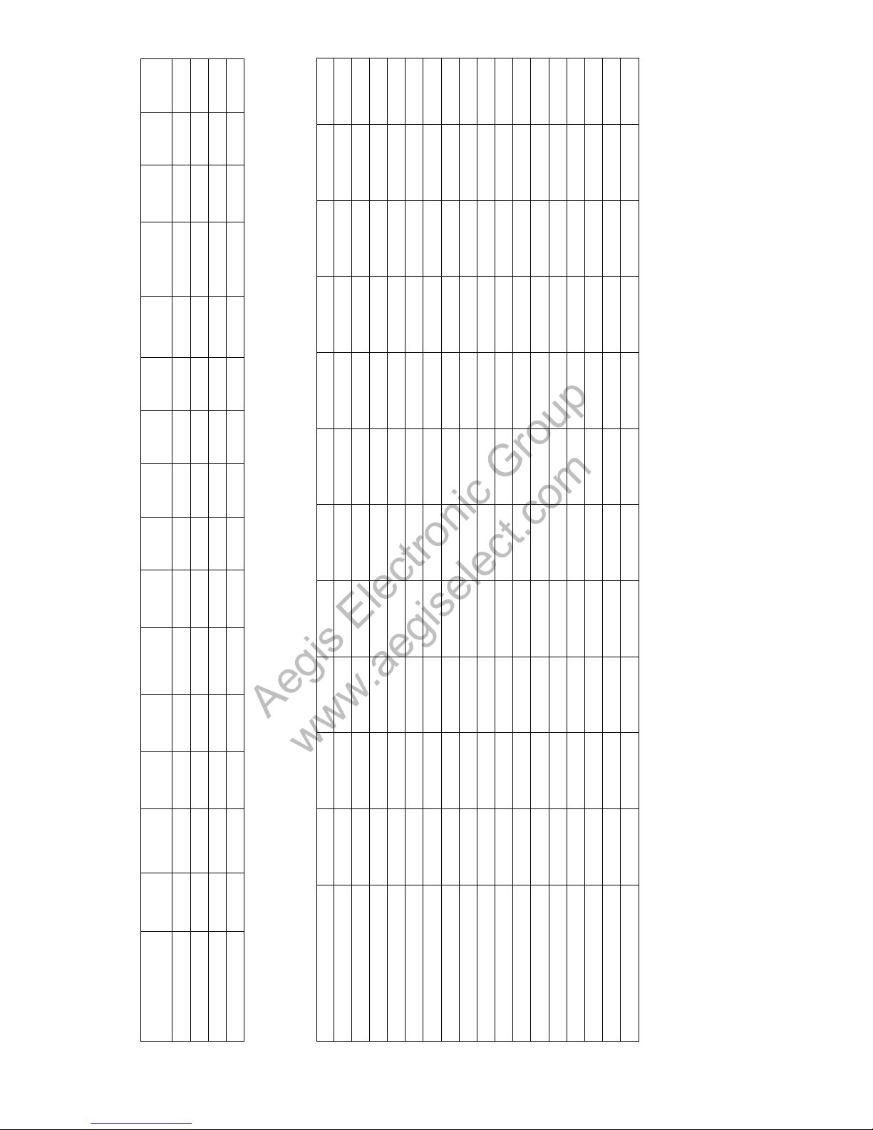
29
Basic Functions
White Balance
Mode Power Off Initializing Power On Freeze On MemRecall WB AUTO Indoor Outdoor
Outdoor
AUTO
Sodium
Lamp
Sodium
Lamp AUTO
Sodium Lamp
Outdoor Auto
OnePush ATW Manual
WB Mode Switchover
On
e Push WB
R
Gain Setting
B
Gain Setting
Exposure
Mode Power Off Initializing Power On Freeze On MemRecall AE Full Auto AE Manual ShutterPri Iris Priority Bright WD/Defog
AE Full Auto
AE
Manual
Shutter
Priority
Iris
Priority
Bright
Shutter
Setting
Iris
Setting
Gain
Setting
Bright
Setting
Slow
Shutter Auto/Manual
Exposure
Compensation On/Off
Exposure
Compensation Setting
BackLight
On/Off
SpotAE
On/Off
SpotAE
Setting
WD
On/Off
Defog
On/Off
Aegis Electronic Group
www.aegiselect.com
Page 30
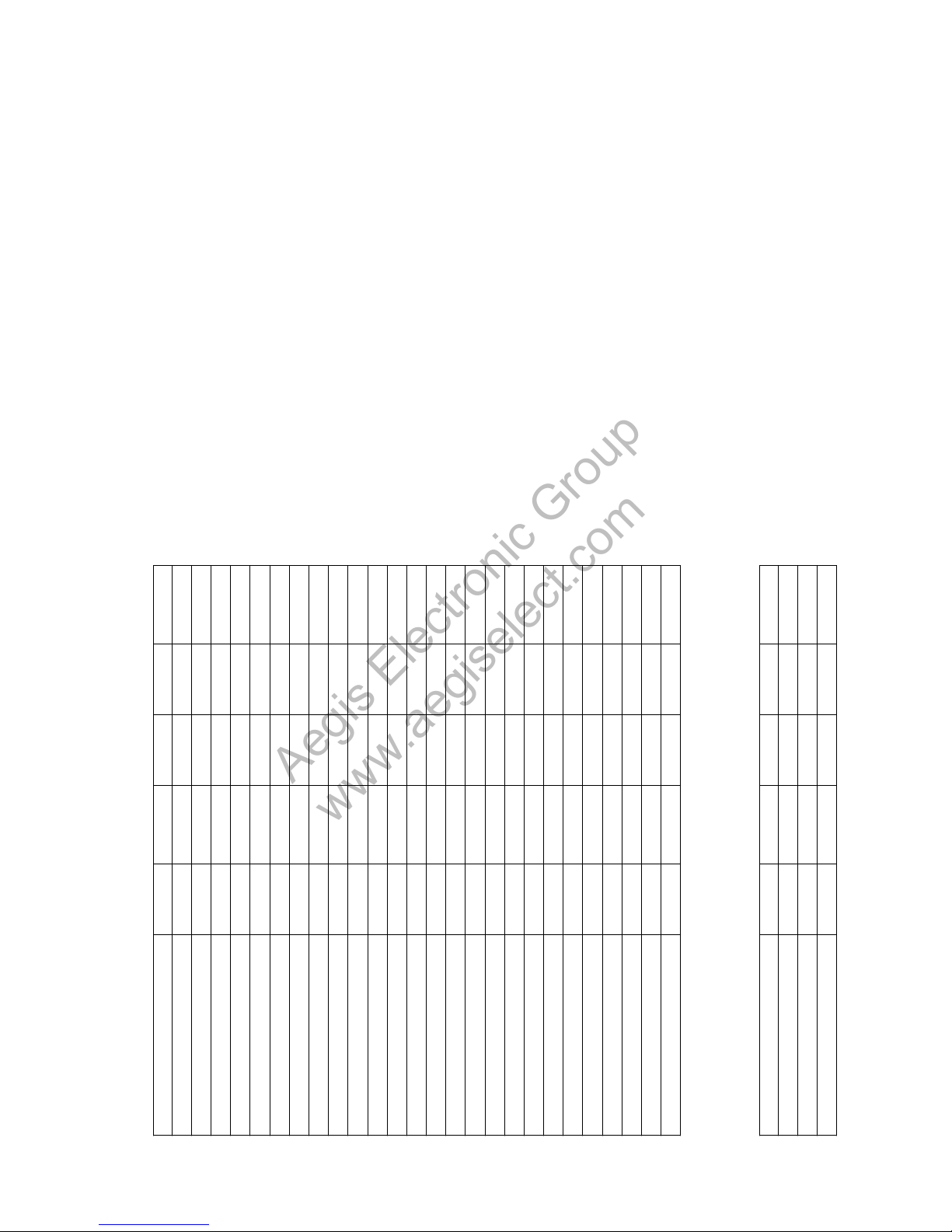
30
Basic Functions
Others
Mode
Power Off Initializing Power On Freeze On MemRecall
A
perture Setting
H
igh Resolution Mode On/Off
LR_R
everse On/Off
F
reeze On/Off
P
icture Effect Setting
I
CR On/Off
A
uto ICR On/Off
A
uto ICR Threshold Level Setting
A
uto ICR Alarm On/Off
I
mage Stabilizer On/Off/Hold
Di
splay On/Off
M
ute On/Off
T
itle Setting
M
ask On/Off
M
ask Setting
K
ey Lock On/Off
A
larm On/Off
A
larm Mode
MD
On/Off
MD
Function Setting
MD
Window Setting
ID
Write
M
emory Save
R
egister Value Setting
C
olor Enhancement On/Off
NR
Level Setting
External Synchronization
Mode
Power Off Initializing Power On Freeze On MemRecall
E
xternal Lock Mode
V
-Phase Up/Down/Stop/Reset
V
-Phase Direct
Aegis Electronic Group
www.aegiselect.com
Page 31

31
Command List
Command List
VISCA1)/RS-232C
Commands
This Manual outlines an RS-232 control protocol and
command list for certain Sony cameras from which
control software can be developed.
THIS CONTROL PROTOCOL AND COMMAND
LIST IS PROVIDED BY SONY ON AN “AS-IS BASIS”
WITHOUT WARRANTY OF ANY KIND. SONY
DOES NOT WARRANT ANY PARTICULAR RESULT
FROM THE USE OF THIS CONTROL PROTOCOL
AND COMMAND LIST AND DISCLAIMS AND
EXCLUDES ALL WARRANTIES. EXPRESS OR
IMPLIED, WITH RESPECT TO THAT CONTROL
PROTOCOL AND COMMAND LIST, INCLUDING,
BUT NOT LIMITED TO, ANY OR ALL IMPLIED
WARRANTIES OF MERCHANTABILITY OR
FITNESS FOR A PARTICULAR PURPOSE. IN FACT,
SONY SPECIFICALLY ACKNOWLEDGES THAT
SOFTWARE DEVELOPED BASED ON THIS
CONTROL PROTOCOL AND COMMAND LIST
MAY CAUSE MALFUNCTION OR DAMAGE TO
HARDWARE AND SOFTWARE USED WITH IT
(INCLUDING SONY HARDWARE AND
SOFTWARE) AND SPECIFICALLY DISCLAIMS
ANY LIABILITY FOR ANY SUCH MALFUNCTION
OR DAMAGE. THIS CONTROL PROTOCOL AND
COMMAND LIST SHOULD BE USED WITH
CAUTION.
Overview of VISCA
In VISCA, the device outputting commands, for
example, a computer, is called the controller. The
device receiving the commands, an FCB camera is
called the peripheral device. In VISCA, up to seven
peripheral devices like the FCB camera can be
connected to one controller using communication
conforming to the RS-232C standard. The parameters
of RS-232C are as follows.
Communication speed: 9.6 kbps/19.2 kbps/38.4 kbps
Data bits : 8
Start bit : 1
Stop bit : 1
Non parity
Flow control using XON/XOFF and RTS/CTS, etc., is
not supported.
..............................................................................................................................................................................................................................
1) VISCA is a protocol which controls consumer camcorders developed by Sony. “VISCA” is a trademark of Sony Corporation.
Aegis Electronic Group
www.aegiselect.com
Page 32
32
Command List
VISCA Communication
Specifications
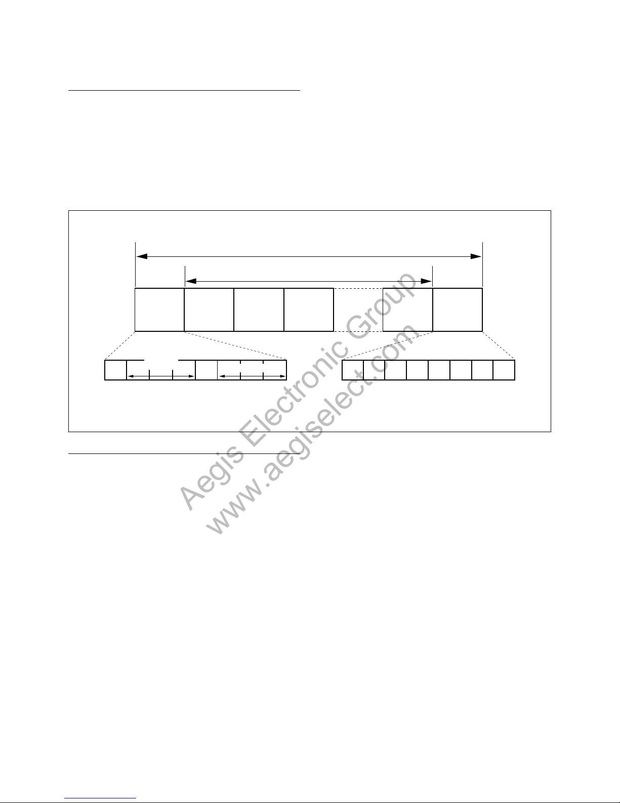
VISCA packet structure
The basic unit of VISCA communication is called a
packet. The first byte of the packet is called the header
and comprises the sender’s and receiver’s addresses. For
example, the header of the packet sent to the FCB
camera assigned address 1 from the controller (address
0) is hexadecimal 81H. The packet sent to the camera
assigned address 2 is 82H. In the command list, as the
header is 8X, input the address of the camera at X. The
header of the reply packet from the camera assigned
address 1 is 90H. The packet from the camera assigned
address 2 is A0H.
Some of the commands for setting cameras can be sent
to all devices at one time (broadcast). In the case of
broadcast, the header should be hexadecimal 88H.
When the terminator is FFH, it signifies the end of the
packet.
Command and inquiry
Command
Sends operational commands to the FCB camera.
Inquiry
Used for inquiring about the current state of the FCB
camera.
Command Packet Note
Inquiry 8X QQ RR ... FF QQ
1)
= Command/Inquiry,
RR
2)
= category code
1)
QQ = 01 (Command), 09 (Inquiry)
2)
RR = 00 (Interface), 04 (camera 1), 06 (Pan/Tilter), 07 (camera 2)
X = 1 to 7: FCB camera address
Bit 7
(MSB)
Bit 6 Bit 5 Bit 4 Bit 3 Bit 2 Bit 1 Bit 0
(LSB)
1 0
FF
Bit 7
(MSB)
Bit 6 Bit 5 Bit 4 Bit 3 Bit 2 Bit 1 Bit 0
(LSB)
1 1 1 1 1 1 1 1
Header
Message (1 to 14 bytes)
Packet (3 to 16 bytes)
Terminator
Byte 1 Byte 3Byte 2
Sender’s
address
Receiver’s address
Aegis Electronic Group
www.aegiselect.com
Page 33

33
Command List
Responses for commands and inquiries
Acknowledge message
Returned
by the FCB camera when it receives a
command. No Acknowledge message is returned for
inquiries.
Completion message
Returned by the FCB camera when execution of
commands or inquiries is completed. In the case of
inquiry commands, it will contain reply data for the
inquiry after the 3rd byte of the packet. If the
Acknowledge message is omitted, the socket number
will contain 0.
Reply Packet Note
Acknowledge X0 4Y FF Y = socket number
Completion (commands) X0 5Y FF Y = socket number
Completion (Inquiries) X0 5Y ... FF Y = socket number
X = 9 to F: FCB camera address + 8
Error message
When a command or inquiry command could not
be executed or failed, an error message is returned
instead of the completion message.
Error Packet Description
X0 6Y 01 FF Message length error (>14 bytes)
X0 6Y 02 FF Syntax Error
X0 6Y 03 FF Command buffer full
X0 6Y 04 FF Command cancelled
X0 6Y 05 FF No socket (to be cancelled)
X0 6Y 41 FF Command not executable
X = 9 to F: FCB camera address + 8, Y = socket number
Socket number
When command messages are sent to the FCB camera,
it is normal to send the next command message after
waiting for the completion message or error message to
return. However to deal with advanced uses, the FCB
camera has two buffers (memories) for commands, so
that up to two commands including the commands
currently being executed can be received. When the
FCB camera receives commands, it notifies the sender
which command buffer was used using the socket
number of the Acknowledge message. As the
completion message or error message also has a socket
number, it indicates which command has ended. Even
when two command buffers are being used at any one
time, an FCB camera management command and some
inquiry messages can be executed.
The Acknowledge message is not returned for these
commands and inquiries, and only the completion
message of socket number 0 is returned.
Command execution cancel
To cancel a command which has already been sent,
send the Cancel command as the next command. To
cancel one of any two commands which have been
sent, use the cancel message.
Cancel Packet Note
Cancel 8X 2Y FF Y = socket number
X = 1 to 7: FCB camera address, Y = socket number
An error message will be returned for this command,
but this is not a fault. It indicates that the command has
been canceled.
Aegis Electronic Group
www.aegiselect.com
Page 34

34
Command List
VISCA Device Setting Command
Before starting control of the FCB camera, be sure to
send the Address command and the IF_Clear
command using the broadcast function.
For VISCA network administration
Address
Sets an address of a peripheral device. Use when
initializing the network, and receiving the following
network change message.
Network Change
Sent from the peripheral device to the controller
when a device is removed from or added to the
network. The address must be re-set when this
message is received.
Packet Note
Address 88 30 01 FF Always broadcasted.
Network Change X0 38 FF
X = 9 to F: FCB camera address + 8
VISCA interface command
IF_Clear
Clears the command buffers in the FCB camera and
cancels the command currently being executed.
Command Packet Reply Packet Note
IF_Clear 8X 01 00 01FF X0 50 FF
IF_Clear (broadcast) 88 01 00 01 FF 88 01 00 01 FF
X = 1 to 7: FCB camera board address (For inquiry packet)
X = 9 to F: FCB camera board address +8 (For reply packet)
VISCA interface and inquiry
CAM_VersionInq
Returns information on the VISCA interface.
Inquiry Inquiry Packet Reply Packet Description
CAM_VersionInq 8X 09 00 02 FF Y0 50 GG GG HH HH JJ JJ KK FF GGGG = Vender ID
(0020: Sony)
HHHH = Model ID
0477: FCB-EX2700
0478: FCB-EX2700P
JJJJ = ROM revision
KK = Maximum socket #(02)
X = 1 to 7: FCB camera address (For inquiry packet)
X = 9 to F: FCB camera address +8 (For reply packet)
Aegis Electronic Group
www.aegiselect.com
Page 35
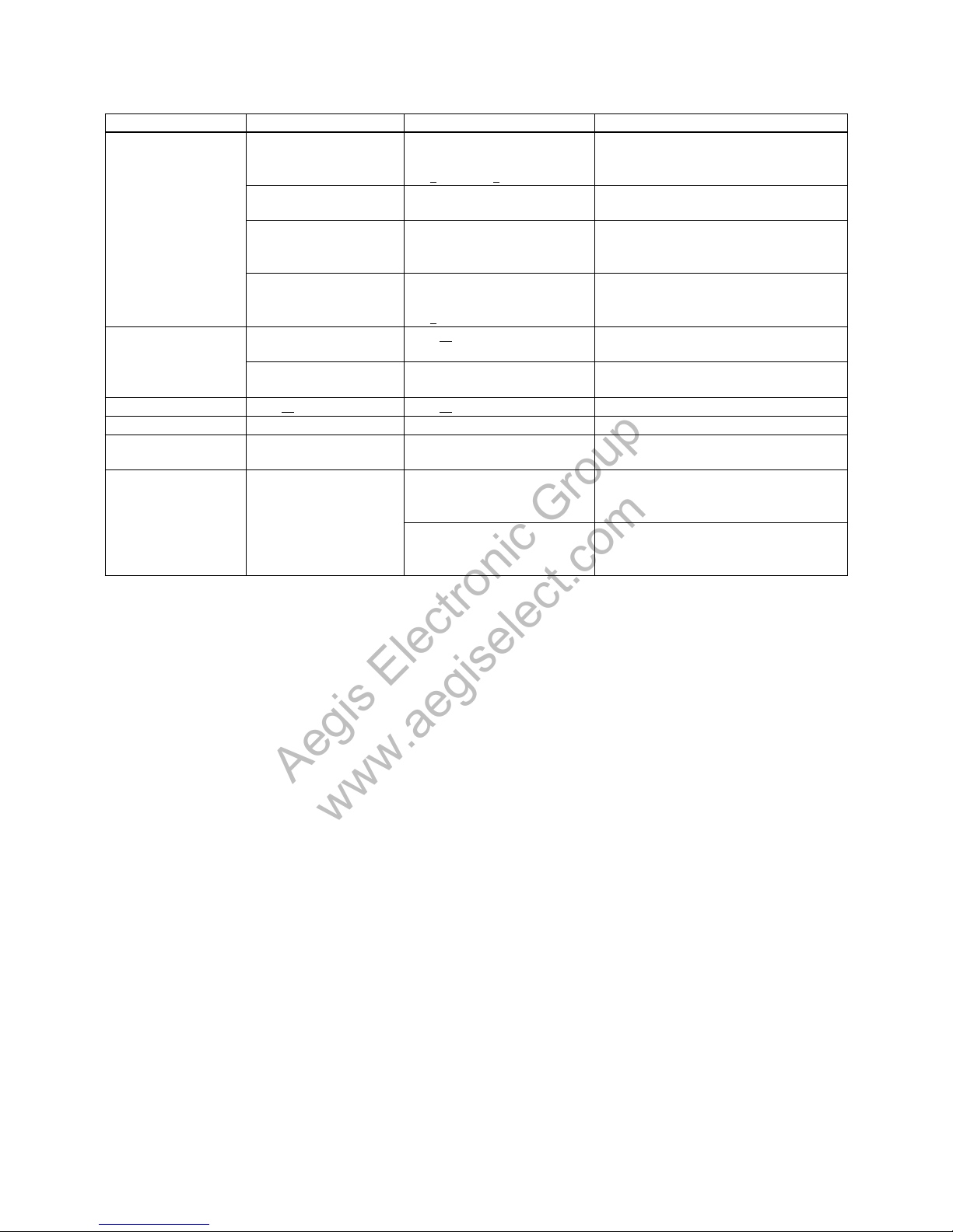
35
Command List
VISCA Command/Acknowledge Protocol
Command Command Message Reply Message Comments
General Command 81 01 04 38 02 FF
(Example)
90 41 FF (Acknowledge)+90 51 FF
(Completion)
90
42
FF 90 52 FF
Returns Acknowledge when a command has
been accepted, and Completion when a
command has been executed.
81 01 04 38 FF
(Example)
90
60 02 FF (Syntax Error) Accepted a command which is not supported
or a command lacking parameters.
81 01 04 38 02 FF
(Example)
90
60 03 FF
(Command Buffer Full)
There are two commands currently being
executed, and the command could not be
accepted.
81
01 04 08 02 FF
(Example)
90 61 41 FF
(Command Not Executable)
90 6
2
41FF
Could not execute the command in the
current mode.
Inquiry Command 81 09 04 38 FF
(Example)
90 50 02 FF (Completion) Acknowledge is not returned for the inquiry
command.
81
09 05 38 FF
(Example)
90
60 02 FF (Syntax Error) Accepted a command which is not supported.
Address Set
88 30 01 FF 88 30 02 FF Returned the device address to +1.
IF_Clear(Broadcast) 88
01 00 01 FF 88 01 00 01 FF Returned the same command.
IF_Clear (For x) 8x 01 00 01 FF z0 50 FF (Completion) Acknowledge is not returned for this
command.
C
ommand Cancel 8x 2y FF z0 6y 04 FF
(Command Canceled)
Returned when the command of the socket
specified is canceled. Completion for the
command canceled is not returned.
z0 6y 05 FF (No Socket) Returned when the command of the specified
socket has already been completed or when
the socket number specified is wrong.
Aegis Electronic Group
www.aegiselect.com
Page 36
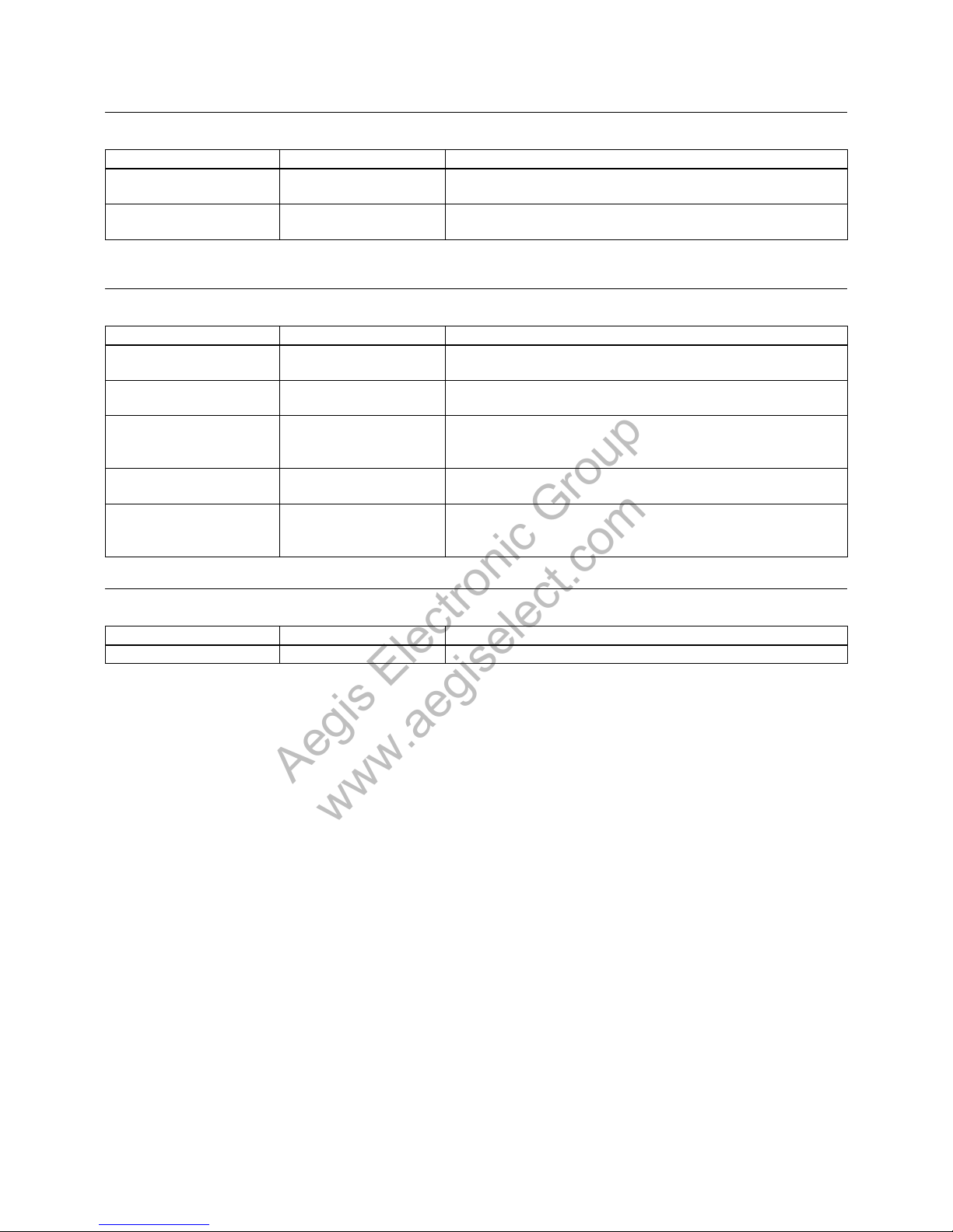
36
Command List
VISCA Camera-Issued Messages
Acknowledge/Completion Messages
Command Messages Comments
Acknowledge z0
4y FF
(y:Socket No.)
Returned when the command is accepted.
Completion z0
5y FF
(y:Socket No.)
Returned when the command has been executed.
z = Device address + 8
Error Messages
Command Messages Comments
Syntax Error z0 60 02 FF Returned when the command format is different or when a command with
illegal command parameters is accepted.
Command Buffer Full z0 60 03 FF Indicates that two sockets are already being used (executing two
commands) and the command could not be accepted when received.
Command Canceled z0 6y 04 FF
(y:Socket No.)
Returned when a command which is being executed in a socket specified
by the cancel command is canceled. The completion message for the
command which is being executed is not returned.
No Socket z0 6y 05 FF
(y:Socket No.)
Returned when no command is executed in a socket specified by the
cancel command, or when an invalid socket number is specified.
Command Not Executable z0 6y 41 FF
(y:Socket No.)
Returned when a command cannot be executed due to current conditions.
For example, when commands controlling the focus manually are received
during auto focus.
Network Change Message
Command Messages Comments
Network Change z0 38 FF Issued when power is being routed.
Aegis Electronic Group
www.aegiselect.com
Page 37
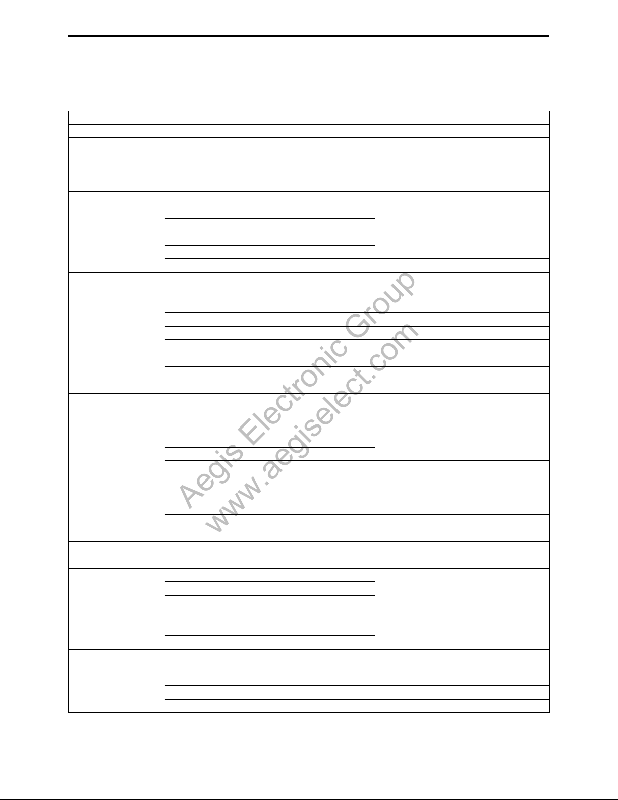
37
Command List
FCB Camera Commands
Command List (1/6)
Command Set Command Command Packet Comments
AddressSet Broadcast 88
30 01 FF Address setting
IF_Clear Broadcast 88
01 00 01 FF I/F Clear
CommandCancel — 8x
2p FF p: Socket No. (=1 or 2)
CAM_Power On 8x
01 04 00 02 FF Power ON/OFF
Off 8x
01 04 00 03 FF
CAM_Zoom Stop 8x
01 04 07 00 FF —
Tele(Standard) 8x
01 04 07 02 FF
Wide(Standard) 8x
01 04 07 03 FF
Tele(Variable) 8x
01 04 07 2p FF p=0 (Low) to 7 (High)
Wide(Variable) 8x
01 04 07 3p FF
Direct 8x
01 04 47 0p 0q 0r 0s FF pqrs: Zoom Position
CAM_DZoom On 8x
01 04 06 02 FF Digital zoom ON/OFF
Off 8x
01 04 06 03 FF
Combine Mode 8x 01 04 36 00 FF Optical/Digital Zoom Combined
Separate Mode 8x 01 04 36 01 FF Optical/Digital Zoom Separate
Stop 8x
01 04 06 00 FF —
Tele(Variable) 8x
01 04 06 2p FF p=0 (Low) to 7 (High)
Wide(Variable) 8x
01 04 06 3p FF
x1/Max 8x
01 04 06 10 FF x1/MAX Magnification Switchover
Direct 8x
01 04 46 00 00 0p 0q FF pq: D-Zoom Position
CAM_Focus Stop 8x
01 04 08 00 FF —
Far(Standard) 8x
01 04 08 02 FF
Near(Standard) 8x
01 04 08 03 FF
Far(Variable) 8x
01 04 08 2p FF p=0 (Low) to 7 (High)
Near(Variable) 8x
01 04 08 3p FF
Direct 8x
01 04 48 0p 0q 0r 0s FF pqrs: Focus Position
Auto Focus 8x 01 04 38 02 FF AF ON/OFF
Manual Focus 8x 01 04 38 03 FF
Auto/Manual 8x
01 04 38 10 FF
One Push Trigger 8x 01 04 18 01 FF One Push AF Trigger
Near Limit 8x 01 04 28 0p 0q 0r 0s FF pqrs: Focus Near Limit Position
AF Sensitivity
Normal 8x
01 04 58 02 FF AF Sensitivity High/Low
Low 8x
01 04 58 03 FF
CAM_AFMode N
ormal AF 8x 01 04 57 00 FF AF Movement Mode
Interval AF 8x 01 04 57 01 FF
Zoom Trigger AF 8x 01 04 57 02 FF
Active/Interval Time 8x 01 04 27 0p 0q 0r 0s FF pq: Movement Time, rs: Interval
CAM_IRCorrection Standard 8x
01 04 11 00 FF FOCUS IR compensation data switching
IR Light 8x 01 04 11 01 FF
CAM_ZoomFocus Direct 8x
01 04 47 0p 0q 0r 0s
0t 0u 0v 0w FF
pqrs: Zoom Position
tuvw: Focus Position
CAM_Initialize Lens 8x
01 04 19 01 FF Lens Initialization Start
Comp Scan 8x 01 04 19 02 FF Correction of CCD pixel blemishes
camera 8x
01 04 19 03 FF System reset
Aegis Electronic Group
www.aegiselect.com
Page 38

38
Command List
Command List (2/6)
Command Set Command Command Packet Comments
CAM_WB Auto 8x
01 04 35 00 FF Normal Auto
Indoor 8x
01 04 35 01 FF Indoor mode
Outdoor 8x
01 04 35 02 FF Outdoor mode
One Push WB 8x 01 04 35 03 FF One Push WB mode
ATW 8x
01 04 35 04 FF Auto Tracing White Balance
Manual 8x
01 04 35 05 FF Manual Control mode
One Push Trigger 8x 01 04 10 05 FF One Push WB Trigger
Outdoor Auto 8x 01 04 35 06 FF Outdoor auto
Sodium Lamp Auto 8x 01 04 35 07 FF Auto including sodium lamp source
Sodium Lamp 8x 01 04 35 08 FF Sodium lamp source fixed mode
CAM_RGain Reset 8x
01 04 03 00 FF Manual Control of R Gain
Up 8x
01 04 03 02 FF
Down 8x
01 04 03 03 FF
Direct 8x
01 04 43 00 00 0p 0q FF pq: R Gain
CAM_BGain Reset 8x
01 04 04 00 FF Manual Control of B Gain
Up 8x
01 04 04 02 FF
Down 8x
01 04 04 03 FF
Direct 8x
01 04 44 00 00 0p 0q FF pq: B Gain
CAM_AE F
ull Auto 8x 01 04 39 00 FF Automatic Exposure mode
Manual 8x
01 04 39 03 FF Manual Control mode
Shutter Priority 8x 01 04 39 0A FF Shutter Priority Automatic Exposure mode
Iris Priority 8x 01 04 39 0B FF Iris Priority Automatic Exposure mode
Bright 8x
01 04 39 0D FF Bright Mode (Manual control)
CAM_SlowShutter Auto 8x
01 04 5A 02 FF Auto Slow Shutter ON/OFF
Manual 8x
01 04 5A 03 FF
CAM_Shutter Reset 8x
01 04 0A 00 FF Shutter Setting
Up 8x
01 04 0A 02 FF
Down 8x
01 04 0A 03 FF
Direct 8x
01 04 4A 00 00 0p 0q FF pq: Shutter Position
CAM_Iris Reset 8x
01 04 0B 00 FF Iris Setting
Up 8x
01 04 0B 02 FF
Down 8x
01 04 0B 03 FF
Direct 8x
01 04 4B 00 00 0p 0q FF pq: Iris Position
CAM_Gain Reset 8x
01 04 0C 00 FF Gain Setting
Up 8x
01 04 0C 02 FF
Down 8x
01 04 0C 03 FF
Direct 8x
01 04 4C 00 00 0p 0q FF pq: Gain Position
Gain Limit 8x 01 04 2C 0p FF p: Gain Position
CAM_Bright Reset 8x
01 04 0D 00 FF Bright Setting
Up 8x
01 04 0D 02 FF
Down 8x
01 04 0D 03 FF
Direct 8x
01 04 4D 00 00 0p 0q FF pq: Bright Position
Aegis Electronic Group
www.aegiselect.com
Page 39
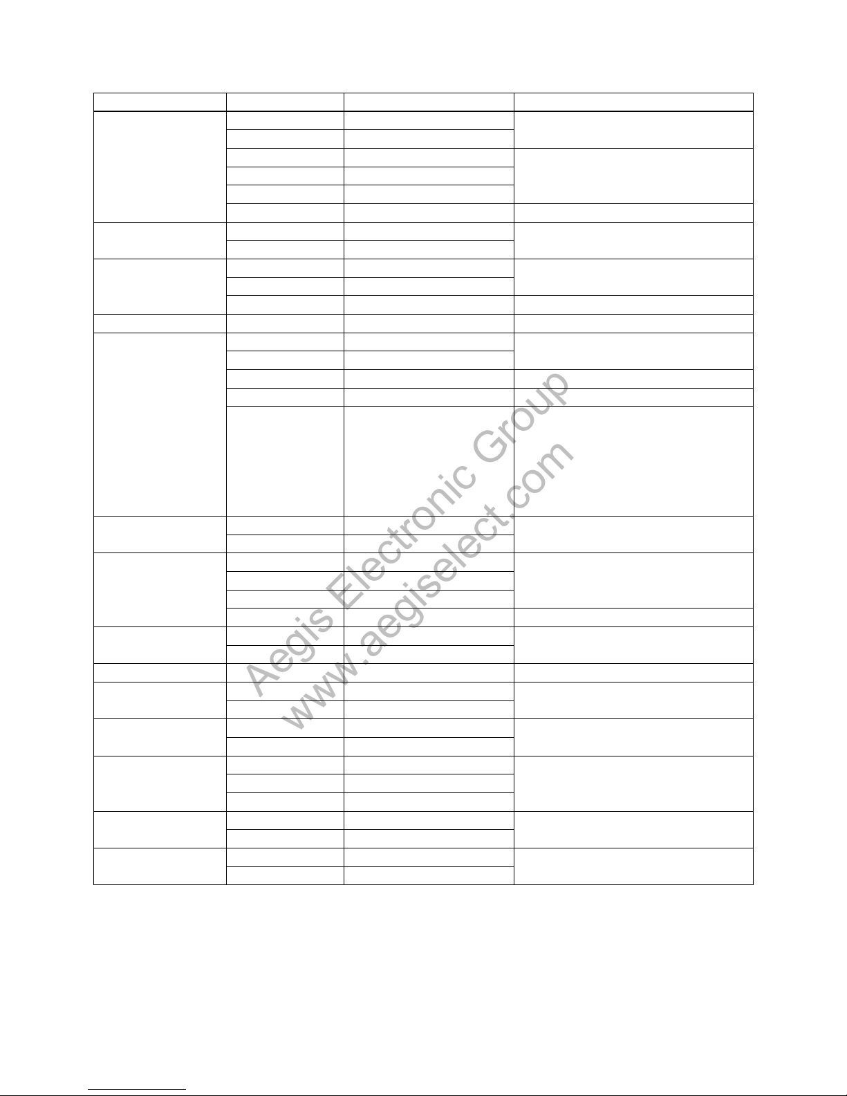
39
Command List
Command List (3/6)
Command Set Command Command Packet Comments
CAM_ExpComp On 8x
01 04 3E 02 FF Exposure Compensation ON/OFF
Off 8x
01 04 3E 03 FF
Reset 8x
01 04 0E 00 FF Exposure Compensation Amount Setting
Up 8x
01 04 0E 02 FF
Down 8x
01 04 0E 03 FF
Direct 8x
01 04 4E 00 00 0p 0q FF pq: ExpComp Position
CAM_Backlight On 8x
01 04 33 02 FF Back Light Compensation ON/OFF
Off 8x
01 04 33 03 FF
CAM_SpotAE On 8x
01 04 59 02 FF Spot Automatic Exposure Setting
Off 8x
01 04 59 03 FF
Position 8x
01 04 29 0p 0q 0r 0s FF pq: X (0 to F), rs: Y (0 to F)
CAM_AE_Response DIRECT 8x
01 04 5D pp FF Automatic Exposure Response Setting (01 to 30)
CAM_WD On 8x
01 04 3D 02 FF WideD ON/OFF
Off 8x
01 04 3D 03 FF
On (RatioFix) 8x 01 04 3D 01 FF WideD ON (Fixed exposure ratio mode)
On (VE) 8x 01 04 3D 06 FF VE Mode
Set Parameter 8x 01 04 2D 0p 00 00 00
0t 0u 0v 0w FF
p: Screen display
0: Combined image, 1: Long/short division,
2: Long-time, 3: Short-time
tu: Exposure ratio of short exposure (x1 to x128)
v: Maximum gain (0: low 1: middle 2: high)
w: 0: low intensity priority, 1: balance, 2: high
intensity priority
CAM_Defog On 8x
01 04 37 02 00 FF Defog Mode ON/OFF
Off 8x
01 04 37 03 00 FF
CAM_Aperture Reset 8x
01 04 02 00 FF Aperture Control
Up 8x
01 04 02 02 FF
Down 8x
01 04 02 03 FF
Direct 8x
01 04 42 00 00 0p 0q FF pq: Aperture Gain
CAM_HR On 8x
01 04 52 02 FF High-Resolusion Mode ON/OFF
Off 8x
01 04 52 03 FF
CAM_NR — 8x
01 04 53 0p FF p: NR Setting (0: OFF, level 1 to 5)
CAM_LR_Reverse On 8x
01 04 61 02 FF Mirror Image ON/OFF
Off 8x
01 04 61 03 FF
CAM_Freeze On 8x
01 04 62 02 FF Still Image ON/OFF
Off 8x
01 04 62 03 FF
CAM_PictureEffect Off 8x
01 04 63 00 FF Picture Effect Setting
Neg.Art 8x
01 04 63 02 FF
B&W 8x
01 04 63 04 FF
CAM_PictureFlip On 8x
01 04 66 02 FF Picture flip ON/OFF
Off 8x
01 04 66 03 FF
CAM_ICR On 8x
01 04 01 02 FF Infrared Mode ON/OFF
Off 8x
01 04 01 03 FF
Aegis Electronic Group
www.aegiselect.com
Page 40
40
Command List
Command List (4/6)
Command Set Command Command Packet Comments
CAM_AutoICR On 8x
01 04 51 02 FF Auto ICR mode On/Off
Off 8x
01 04 51 03 FF
Threshold 8x
01 04 21 00 00 0p 0q FF
pq: ICR ON
OFF threshold level
CAM
_AutoICRAlarmReply
On 8x
01 04 31 02 FF Auto ICR switching Alarm ON/OFF
Off 8x
01 04 31 03 FF
(Reply) y0
07 04 31 02 FF
ICR OFF ON
y0 07 04 31 03 FF
ICR ON
OFF
CAM_Stabilizer On 8x
01 04 34 02 FF Hand shake correction ON/OFF
Off 8x
01 04 34 03 FF
Hold 8x
01 04 34 00 FF Hand shake correction hold
CAM_Memory Reset 8x
01 04 3F 00 0p FF p: Memory Number (=0 to 5)
Set 8x
01 04 3F 01 0p FF
Recall 8x
01 04 3F 02 0p FF
CAM_CUSTOM Reset 8x
01 04 3F 00 7F FF Starts up in this mode when the power is turned
on.
Set 8x
01 04 3F 01 7F FF
Recall 8x
01 04 3F 02 7F FF
CAM_Display On 8x
01 04 15 02 FF
(8x 01 06 06 02 FF)
Display ON/OFF
Off 8x
01 04 15 03 FF
(8x 01 06 06 03 FF)
On/Off 8x
01 04 15 10 FF
(8x 01 06 06 10 FF)
CAM_Title T
itle Set1 8x 01 04 73 00 mm nn pp qq 00 00
00 00 00 00 FF
mm: V-Psition, nn: H-Position
pp: Color, qq: Blink
Title Set2 8x 01 04 73 01 mm nn pp qq rr ss
tt uu vv ww FF
mnpqrstuvw: Display character setting
(1st to 10th character)
Title Set3 8x 01 04 73 02 mm nn pp qq rr ss
tt uu vv ww FF
mnpqrstuvw: Display character setting
(11th to 20th character)
Title Clear 8x 01 04 74 00 FF Clear title setting
On 8x
01 04 74 02 FF Title display ON/OFF
Off 8x
01 04 74 03 FF
CAM_MultiLineTitle T
itle Set1 8x 01 04 73 1L 00 nn pp
qq rr 00 00 00 00 00 FF
L: Line Number, nn: H-position
pp: Color, qq: Blink rr: Opening Title
Title Set2 8x 01 04 73 2L mm nn pp
qq rr ss tt uu vv ww FF
L: Line Number,
mnpqrstuvw: Setting of characters
(1st to 10th character)
Title Set3 8x 01 04 73 3L mm nn pp
qq rr ss tt uu vv ww FF
L: Line Number,
mnpqrstuvw: Setting of characters
(11th to 20th character)
Title Clear 8x 01 04 74 1p FF Title Setting clear (p: 0 to a, f= all lines)
On 8x
01 04 74 2p FF Title display On/Off (0 to a, f= all lines)
Off 8x
01 04 74 3p FF
CAM_Mute On 8x
01 04 75 02 FF Muting ON/OFF
Off 8x
01 04 75 03 FF
On/Off 8x
01 04 75 10 FF
Aegis Electronic Group
www.aegiselect.com
Page 41
41
Command List
Command List (5/6)
Command Set Command Command Packet Comments
CAM_PrivacyZone SetMask 8x
01 04 76 mm nn
0r 0r 0s 0s FF
mm: Mask Settings
nn 00: Modify, 01: New
rr: W, ss:H
Display 8x
01 04 77 pp pp pp pp FF Mask Display ON/OFF
pp pp pp pp: Mask Settings (0:OFF, 1:ON)
SetMaskColor 8x
01 04 78 pp pp pp pp
qq rr FF
pp pp pp pp: Mask Color Settings
qq: Color Setting when 0 is selected
rr: Color Setting when 1 is selected
SetPanTiltAngle 8x 01 04 79 0p 0p 0p
0q 0q 0q FF
Pan/Tilt Angle Settings
ppp: Pan
qqq: Tilt
SetPTZMask 8x
01 04 7B mm 0p 0p 0p
0q 0q 0q 0r 0r 0r 0r FF
Pan/Tilt/Zoom Settings for Mask
ppp: Pan, qqq: Tilt, rrrr: Zoom
Non_InterlockMask 8x
01 04 6F mm
0p 0p 0q 0q 0r 0r 0s 0s FF
mm: Non_Interlock Mask Settings
pp: X, qq: Y, rr: W, ss: H
GridOn 8x
01 04 7C 02 FF Grid Display ON/OFF
GridOff 8x
01 04 7C 03 FF Grid/Center Line Display Off
CenterLineOn 8x
01 04 7C 04 FF Center Line Display On
CAM_KeyLock Off 8x
01 04 17 00 FF Camera Control Enable/Disable
On 8x
01 04 17 02 FF
CAM_IDWrite — 8x
01 04 22 0p 0q 0r 0s FF pqrs: Camera ID (=0000 to FFFF)
CAM_MemSave Write 8x
01 04 23 0m 0p 0q 0r 0s FF m: Address (=0 to 7)
pqrs: Data (0000 to FFFF)
CAM_ExtLock I
nternal Mode 8x 01 04 55 00 FF Internal Sync
Line Lock Mode 8x 01 04 55 01 FF V-Phase Adjustment
Frequency Lock Mode 8x 01 04 55 02 FF External Sync
CAM_VPhase Stop 8x
01 04 05 00 FF —
Up 8x
01 04 05 02 FF
Down 8x
01 04 05 03 FF
Up (Step) 8x 01 04 05 2p FF p=step (1 to 7)
Down (Step) 8x 01 04 05 3p FF
Reset 8x
01 04 05 40 FF Restore Factory Settings
Direct 8x
01 04 45 0p 0q 0r 0s FF pqrs: V-Phase (0000 to)
(NTSC: 0000 to 20Chex, PAL: 0000 to 270hex)
CAM_Alarm On 8x
01 04 6B 02 FF Alarm ON/OFF
Off 8x
01 04 6B 03 FF
SetMode 8x
01 04 6C pp FF pp: Mode setting
00 Focus change detection
(reference value is not updated)
01 Focus change detection
(reference value is updated)
02 AE change detection
(r
eference value is not updated)
03 AE change detection
(r
eference value is updated)
:
0C Day/Night judgement
SetDayNighLevel 8x
01 04 6D 0p 0p 0p 0q 0q 0q FF ppp: Day judgement level setting
qqq: Night judgement level setting
Alarm(Reply) y0
07 04 6B 01 FF
Detection level “Low” “High”
y0 07 04 6B 00 FF
Detection level “High” “Low”
Aegis Electronic Group
www.aegiselect.com
Page 42
42
Command List
Command List (6/6)
Command Set Command Command Packet Comments
CAM_MD On 8x
01 04 1B 02 FF Motion Detection On/Off
Off 8x
01 04 1B 03 FF
Function Set 8x 01 04 1C 0m 0n 0p 0q 0r 0s FF m: Display mode
n: Detection Frame Set (0 to F)
pq: Threshold Level (00 to FF)
rs: Interval Time set (00 to FF)
Window Set 8x 01 04 1D 0m 0p 0q 0r 0s FF m: Select Detection Frame (0, 1, 2, 3)
p: Start Horizontal Position (00 to 0B)
q: Start Vertical Position (00 to 07)
r: Stop Horizontal Position (01 to 0C)
s: Stop Vertical Position (01 to 08)
Alarm (Reply) y0 07 04 1B 0p FF p: Detection Frame Number
CAM_Continuous
ZoomPosReply
On 8x
01 04 69 02 FF ZoomPosition data Continuous Output On/Off
Off 8x
01 04 69 03 FF
(Reply) y0
07 04 69 0p 0p 0q 0q 0q 0q FF pp: D-Zoom Position
* 00: When Zoom Mode is Combine
qqqq: Zoom Position
CAM_
ReplyIntervalTimeSet
— 8x
01 04 6A 00 00 0p 0p FF pp: Interval Time [Vertical timing]
CAM_RegisterValue — 8x
01 04 24 mm 0p 0p FF mm: Register No. (=00 to 7F)
pp: Register Value (=00 to 7F)
CAM_ColorEnhance P
arameter Set 8x 01 04 20 mm nn
pp qq rr ss tt uu FF
mm: Threshold level
nn: Hysteresis width
pp: Fixed color Y of high-intensity side
qq: Fixed color Cr of high-intensity side
rr: Fixed color Cb of high-intensity side
ss: Fixed color Y of low-intensity side
tt: Fixed color Cr of low-intensity side
uu: Fixed color Cb of low-intensity side
* Set 00h to 7Fh for each parameter.
On 8x
01 04 50 02 FF Color Enhancement ON/OFF
Off 8x
01 04 50 03 FF
Aegis Electronic Group
www.aegiselect.com
Page 43
43
Command List
Inquiry Command List (1/3)
Inquiry Command Command Packet Inquiry Packet Comments
CAM_PowerInq 8x
09 04 00 FF y0 50 02 FF On
y0 50 03 FF Off
CAM_ZoomPosInq 8x
09 04 47 FF y0 50 0p 0q 0r 0s FF pqrs: Zoom Position
CAM_DZoomModeInq 8x
09 04 06 FF y0 50 02 FF D-Zoom On
y0 50 03 FF D-Zoom Off
CAM_DZoomC/SModeInq 8x
09 04 36 FF y0 50 00 FF Combine Mode
y0 50 01 FF Separate Mode
CAM_DZoomPosInq 8x
09 04 46 FF y0 50 00 00 0p 0q FF pq: D-Zoom Position
CAM_FocusModeInq 8x
09 04 38 FF y0 50 02 FF Auto Focus
y0 50 03 FF Manual Focus
CAM_FocusPosInq 8x
09 04 48 FF y0 50 0p 0q 0r 0s FF pqrs: Focus Position
CAM_FocusNearLimitInq 8x
09 04 28 FF y0 50 0p 0q 0r 0s FF pqrs: Focus Near Limit Position
CAM_AFSensitivityInq 8x
09 04 58 FF y0 50 02 FF AF Sensitivity Normal
y0 50 03 FF AF Sensitivity Low
CAM_AFModeInq 8x
09 04 57 FF y0 50 00 FF Normal AF
y0 50 01 FF Interval AF
y0 50 02 FF Zoom Trigger AF
CAM_AFTimeSettingInq 8x
09 04 27 FF y0 50 0p 0q 0r 0s FF pq: Movement Time, rs: Interval
CAM_IRCorrectionInq 8x
09 04 11 FF y0 50 00 FF Standard
y0 50 01 FF IR Light
CAM_WBModeInq 8x
09 04 35 FF y0 50 00 FF Auto
y0 50 01 FF In Door
y0 50 02 FF Out Door
y0 50 03 FF One Push WB
y0 50 04 FF
ATW
y0
50 05 FF Manual
y0
50 06 FF Outdoor Auto
y0 50 07 FF Sodium Lamp Auto
y0 50 08 FF Sodium Lamp
CAM_RGainInq 8x
09 04 43 FF y0 50 00 00 0p 0q FF pq: R Gain
CAM_BGainInq 8x
09 04 44 FF y0 50 00 00 0p 0q FF pq: B Gain
CAM_AEModeInq 8x
09 04 39 FF y0 50 00 FF Full Auto
y0 50 03 FF Manual
y0
50 0A FF Shutter Priority
y0 50 0B FF Iris Priority
y0 50 0D FF
Bright
CAM_SlowShutterModeInq 8x
09 04 5A FF y0 50 02 FF Auto
y0 50 03 FF Manual
CAM_ShutterPosInq 8x
09 04 4A FF y0 50 00 00 0p 0q FF pq: Shutter Position
CAM_IrisPosInq 8x
09 04 4B FF y0 50 00 00 0p 0q FF pq: Iris Position
CAM_GainPosInq 8x
09 04 4C FF y0 50 00 00 0p 0q FF pq: Gain Position
CAM_GainLimitInq 8x
09 04 2C FF y0 50 0q FF p: Gain Limit
CAM_BrightPosInq 8x
09 04 4D FF y0 50 00 00 0p 0q FF pq: Bright Position
CAM_ExpCompModeInq 8x
09 04 3E FF y0 50 02 FF On
y0 50 03 FF Off
CAM_ExpCompPosInq 8x
09 04 4E FF y0 50 00 00 0p 0q FF pq: ExpComp Position
CAM_BacklightModeInq 8x
09 04 33 FF y0 50 02 FF On
y0 50 03 FF Off
Aegis Electronic Group
www.aegiselect.com
Page 44
44
Command List
Inquiry Command List (2/3)
Inquiry Command Command Packet Inquiry Packet Comments
CAM_SpotAEModeInq 8x
09 04 59 FF y0 50 02 FF On
y0 50 03 FF Off
CAM_SpotAEPosInq 8x
09 04 29 FF y0 50 0p 0q 0r 0s FF pq: X Position, rs: Y Position
CAM_AE_ResponseInq 8x
09 04 5D FF y0 50 pp FF pp: 01 to 20 (hex)
CAM_WDModeInq 8x
09 04 3D FF y0 50 02 FF On
y0 50 03 FF Off
y0
50 01 FF On(RatioFix)
y0
50 06 FF On(VE)
CAM_WDParameterInq 8x
09 04 2D FF y0 50 0p 00 00 00
0t 0u 0v 0w FF
p: Screen display
tu: Exposure ratio of short exposure
v: Maximum gain
w: Low intensity priority, balance, high
intensity priority
CAM_defogInq 8x
09 04 37 FF y0 50 02 FF On
y0 50 03 FF Off
CAM_ApertureInq 8x
09 04 42 FF y0 50 00 00 0p 0q FF pq: Aperture Gain
CAM_HRModeInq 8x
09 04 52 FF y0 50 02 FF On Hi-Resolution
y0 50 03 FF Off
CAM_NRInq 8x
09 04 53 FF y0 50 0p FF p: NR level
CAM_LR_ReverseModeInq 8x
09 04 61 FF y0 50 02 FF On
y0 50 03 FF Off
CAM_F
reezeModeInq 8x 09 04 62 FF y0 50 02 FF On
y0
50 03 FF Off
CAM_PictureEffectModeInq 8x
09 04 63 FF y0 50 00 FF Off
y0 50 02 FF Neg.Art
y0
50 04 FF B&W
CAM_PictureFlipModeInq 8x
09 04 66 FF y0 50 02 FF On
y0 50 03 FF Off
CAM_ICRModeInq 8x
09 04 01 FF y0 50 02 FF On
y0 50 03 FF Off
CAM_AutoICRModeInq 8x
09 04 51 FF y0 50 02 FF On
y0 50 03 FF Off
CAM_AutoICRThresholdInq 8x
09 04 21 FF y0 50 00 00 0p 0q FF
pq: ICR ON OFF Threshold Level
CAM_
AutoICRAlarmReplyInq
8x
09 04 31 FF y0 50 02 FF On
y0
50 03 FF Off
CAM_StabilizerModeInq 8x
09 04 34 FF y0 50 02 FF On
y0 50 03 FF Off
y0
50 00 FF Hold
CAM_DisplayModeInq 8x
09 04 15 FF
(8x 09 06 06 FF)
y0 50 02 FF On
y0 50 03 FF Off
CAM_MuteModeInq 8x
09 04 75 FF y0 50 02 FF On
y0 50 03 FF Off
CAM_PrivacyDisplayInq 8x
09 04 77 FF y0 50 pp pp pp pp FF pp pp pp pp: Mask Display (0:OFF, 1:ON)
CAM_PrivacyPanTiltInq 8x
09 04 79 FF y0 50 0p 0p 0p 0q 0q 0q FF ppp: Pan
qqq: Tilt
CAM_PrivacyPTZInq 8x
09 04 7B mm FF y0 50 0p 0p 0p 0q 0q 0q 0r 0r
0r 0r FF
mm: Mask Settings
ppp: Pan
qqq: Tilt
rrr: Zoom
CAM_PrivacyMonitorInq 8x
09 04 6F FF y0 50 pp pp pp pp FF pp pp pp pp: Mask is displayed now.
Aegis Electronic Group
www.aegiselect.com
Page 45
45
Command List
Inquiry Command List (3/3)
Inquiry Command Command Packet Inquiry Packet Comments
CAM_KeyLockInq 8x
09 04 17 FF y0 50 00 FF Off
y0 50 02 FF On
CAM_IDInq 8x
09 04 22 FF y0 50 0p 0q 0r 0s FF pqrs: Camera ID
CAM_MemoryInq 8x
09 04 3F FF y0 50 pp FF pp: Memory number recalled last
CAM_MemSaveInq 8x
09 04 23 0X FF y0 50 0p 0p 0q 0q FF X: 00 to 07 (Address)
ppqq: 0x0000 to 0xFFFF (Data)
CAM_ExtLockInq 8x
09 04 55 FF y0 50 00 FF Internal Sync
y0 50 01 FF V-Phase Adjustment
y0 50 02 FF External Sync
CAM_VPhasePosInq 8x
09 04 45 FF y0 50 0p 0q 0r 0s FF pqrs: V-Phase Position
CAM_VersionInq 8x
09 00 02 FF y0 50 00 20
mn pq rs tu vw FF
mnpq: Model Code (04xx)
rstu: ROM version
vw: Socket Number (=02)
CAM_AlarmInq 8x
09 04 6B FF y0 50 02 FF On
y0 50 03 FF Off
CAM_AlarmModeInq 8x
09 04 6C FF y0 50 pp FF pp: Alarm Mode
CAM_
AlarmDayNightLevelInq
8x
09 04 6D FF y0 50 0p 0p 0p
0q 0q 0q 0r 0r 0r FF
ppp: Day judgement level setting
qqq: Night judgement level setting
rrr: Current Automatic Exposure level setting
CAM_AlarmDetectLevelInq 8x
09 04 6E FF y0 50 01 FF Detection level “High”
y0 50 00 FF Detection level “Low”
CAM_MDModeInq 8x
09 04 1B FF y0 50 02 FF On
y0 50 03 FF Off
CAM_MDFunctionInq 8x
09 04 1C FF y0 50 0m 0n 0p 0q FF m: Display mode
n: Detection Frame Set (0 to F)
pq: Threshold Level (0 to FF)
rs: Interval Time set (0 to FF)
CAM_MDWindowInq 8x
09 04 1D 0m FF y0 50 0p 0q 0r 0s FF m: Select Detection Frame (0, 1, 2, 3)
p: Start Horizontal Position (00 to 0B)
q: Start Vertical Position (00 to 07)
r: Stop Horizontal Position (01 to 0C)
s: Stop Vertical Position (01 to 08)
CAM_ContinuousZoomPos
ReplyModeInq
8x
09 04 69 FF y0 50 02 FF On
y0
50 03 FF Off
CAM_ReplyIntervalTimeInq 8x
09 04 6A FF y0 50 00 00 0p 0p FF pp: Interval Time
CAM_RegisterValueInq 8x
09 04 24 mm FF y0 50 0p 0p ff mm: Register No. (00 to 7F)
pp: Register Value (00 to FF)
CAM_ColorEnhanceInq 8x
09 04 20 FF y0 50 mm nn pp qq rr ss tt uu FF mm: Threshold level
nn: Hysteresis width
pp: Fixed color Y of high-intensity side
qq: Fixed color Cr of high-intensity side
rr: Fixed color Cb of high-intensity side
ss: Fixed color Y of low-intensity side
tt: Fixed color Cr of low-intensity side
uu: Fixed color Cb of low-intensity side
8x 09 04 50 FF y0 50 02 FF
On
y0
50 03 FF Off
CAM_TempInq 8x
09 04 68 FF y0 50 00 00 0p 0p FF pq: Temperature * Lens temperature
Aegis Electronic Group
www.aegiselect.com
Page 46
46
Command List
Block Inquiry Command List
Lens Control System Inquiry Commands Command Packet 8x 09 7E 7E 00 FF
Inquiry Packet
Byte Bit Comments
Packet
0
7
D
estination Address
6
5
4
3
S
ource Address
2
1
0
Packet
1
7 0 C
ompletion Message
(50h)
6 1
5 0
4 1
3 0
2 0
1 0
0 0
Packet
2
7 0
6 0
5 0
4 0
3
Z
oom Position (HH)
2
1
0
Packet
3
7 0
6 0
5 0
4 0
3
Z
oom Position (HL)
2
1
0
Packet
4
7 0
6 0
5 0
4 0
3
Z
oom Position (LH)
2
1
0
Byte Bit Comments
Packet
5
7 0
6 0
5 0
4 0
3
Z
oom Position (LL)
2
1
0
Packet
6
7 0
6 0
5 0
4 0
3
F
ocus Near Limit (H)
2
1
0
Packet
7
7 0
6 0
5 0
4 0
3
F
ocus Near Limit (L)
2
1
0
Packet
8
7 0
6 0
5 0
4 0
3
F
ocus Position (HH)
2
1
0
Packet
9
7 0
6 0
5 0
4 0
3
F
ocus Position (HL)
2
1
0
Packet
10
7 0
6 0
5 0
4 0
3
F
ocus Position (LH)
2
1
0
Byte Bit Comments
Packet
11
7 0
6 0
5 0
4 0
3
F
ocus Position (LL)
2
1
0
Packet
12
7 0
6 0
5 0
4 0
3 0
2 0
1 0
0 0
Packet
13
7 0
6 0
5 DZ
oomMode
(1:Separate, 0:Combine)
4 AF
Mode
(0:Normal, 1:Interval,
2:Zoom Trigger)
3
2 AF
Sensitivity
(1:Normal, 0:Slow)
1 Dig
ital Zoom
(1:On, 0:Off)
0 F
ocus Mode
(1:Auto, 0:Manual)
Packet
14
7 0
6 0
5 0
4 0
3 L
ow Contrast Detection
(1:Yes, 0:No)
2 C
amera Memory Recall
(1:Executing, 0:Stopped)
1 F
ocus Command
(1:Executing, 0:Stopped)
0 Z
oom Command
(1:Executing, 0:Stopped)
Packet
15
7 1 T
erminator (FFh)
6 1
5 1
4 1
3 1
2 1
1 1
0 1
Aegis Electronic Group
www.aegiselect.com
Page 47
47
Command List
Camera Control System Inquiry Commands Command Packet 8x 09 7E 7E 01 FF
Inquiry Packet
Byte Bit Comments
Packet
0
7
D
estination Address
6
5
4
3
S
ource Address
2
1
0
Packet
1
7 0 C
ompletion Message
(50h)
6 1
5 0
4 1
3 0
2 0
1 0
0 0
Packet
2
7 0
6 0
5 0
4 0
3
R
Gain (H)
2
1
0
Packet
3
7 0
6 0
5 0
4 0
3
R
Gain (L)
2
1
0
Packet
4
7 0
6 0
5 0
4 0
3
B
Gain (H)
2
1
0
Byte Bit Comments
Packet
5
7 0
6 0
5 0
4 0
3
B
Gain (L)
2
1
0
Packet
6
7 0
6 0
5 0
4 0
3
WB
Mode
2
1
0
Packet
7
7 0
6 0
5 0
4 0
3
A
perture Gain
2
1
0
Packet
8
7 0
6 0
5 0
4
E
xposure Mode
3
2
1
0
Packet
9
7 0
6 D
efog (1:On, 0:Off)
5 H
ighResolution
(1:On, 0:Off)
4 W
ideD
(1:
Other than Off
, 0:Off)
3 S
potAE (1:On, 0:Off)
2 B
ack Light (1:On, 0:Off)
1 E
xposure Comp.
(1:On, 0:Off)
0 S
low Shutter
(1:Auto, 0:Manual)
Byte Bit Comments
Packet
10
7 0
6 0
5 0
4
S
hutter Position
3
2
1
0
Packet
11
7 0
6 0
5 0
4
I
ris Position
3
2
1
0
Packet
12
7 0
6 0
5 0
4 0
3
Ga
in Position
2
1
0
Packet
13
7 0
6 0
5 0
4
B
right Position
3
2
1
0
Packet
14
7 0
6 0
5 0
4 0
3
E
xposure Comp. Position
2
1
0
Packet
15
7 1
T
erminator (FFh)
6 1
5 1
4 1
3 1
2 1
1 1
0 1
Aegis Electronic Group
www.aegiselect.com
Page 48
48
Command List
Other Inquiry Commands Command Packet 8x 09 7E 7E 02 FF
Inquiry Packet
Byte Bit Comments
Packet
0
7
D
estination Address
6
5
4
3
S
ource Address
2
1
0
Packet
1
7 0 C
ompletion Message
(50h)
6
1
5
0
4
1
3
0
2
0
1
0
0
0
Packet
2
7
0
6
0
5
0
4
0
3 A
uto ICR Alarm
(1:On, 0:Off)
2
A
uto ICR (1:On, 0:Off)
1
K
ey Lock (1:On, 0:Off)
0
P
ower (1:On, 0:Off)
Packet
3
7
0
6
S
tabilizer (0:Off, 2:On, 3:
Hold)
5
4
I
CR (1:On, 0:Off)
3
F
reeze (1:On, 0:Off)
2
LR
Reverse (1:On, 0:Off)
1
0
0
0
Packet
4
7
0
6
0
5 P
rivacy Zone
(1:On, 0:Off)
4
M
ute (1:On, 0:Off)
3 T
itle Display
(1:On, 0:Off)
2
Di
splay (1:On, 0:Off)
1
—
0
—
Byte Bit Comments
Packet
5
7
0
6
0
5
0
4
0
3
P
icture Effect Mode
2
1
0
Packet
6
7
0
6
0
5
0
4
0
3
0
2
0
1
0
0
0
Packet
7
7
0
6
0
5
0
4
0
3
0
2
0
1
0
0
0
Packet
8
7
0
6
0
5
0
4
0
3
C
amera ID (HH)
2
1
0
Packet
9
7
0
6
0
5
0
4
0
3
C
amera ID (HL)
2
1
0
Packet
10
7
0
6
0
5
0
4
0
3
C
amera ID (LH)
2
1
0
Byte Bit Comments
Packet
11
7
0
6
0
5
0
4
0
3
C
amera ID (LL)
2
1
0
Packet
12
7
0
6
0
5 E
xternal Lock
(1:Provided,
0:N
ot provided)
4 M
emory (1:Provided,
0:Not provided)
3 C
lock (1:Provided,
0:Not provided)
2 I
CR (1:Provided,
0:Not provided)
1 S
tabilizer (1:Provided,
0:Not provided)
0 S
ystem
(1:PAL, 0:NTSC)
Packet
13
7
0
6
0
5 E
xternal Lock Status
(1:Lock, 0:Unlock)
4 E
xternal Lock Mode
(1:Line Lock, 0:Internal)
3
V
-Phase (H)
2
1
0
Packet
14
7
0
6
0
5
V
-Phase (L)
4
3
2
1
0
Packet
15
7
1 T
erminator (FFh)
6
1
5
1
4
1
3
1
2
1
1
1
0
1
Aegis Electronic Group
www.aegiselect.com
Page 49
49
Command List
Enlargement Function1 Query Command Command Packet 8x 09 7E 7E 03 FF
Inquiry Packet
Byte Bit Comments
Packet
0
7
D
estination Address
6
5
4
3
S
ource Address
2
1
0
Packet
1
7 0 C
ompletion Message
(50h)
6 1
5 0
4 1
3 0
2 0
1 0
0 0
Packet
2
7 0
6 0
5 0
4 0
3
Dig
ital Zoom Posiition (H)
2
1
0
Packet
3
7 0
6 0
5 0
4 0
3
Dig
ital Zoom Posiition (L)
2
1
0
Packet
4
7 0
6 0
5 0
4 0
3
AF
Activation Time (H)
2
1
0
Byte Bit Comments
Packet
5
7 0
6 0
5 0
4 0
3
AF
Activation Time (L)
2
1
0
Packet
6
7 0
6 0
5 0
4 0
3
AF
Interval Time (H)
2
1
0
Packet
7
7 0
6 0
5 0
4 0
3
AF
Interval Time (L)
2
1
0
Packet
8
7 0
6 0
5 0
4 0
3
S
potAE Position (X)
2
1
0
Packet
9
7 0
6 0
5 0
4 0
3
S
potAE Position (Y)
2
1
0
Packet
10
7 0
6 0
5 0
4 0
3 0
2 MD
(1:On, 0:Off)
1 A
larm (1:On, 0:Off)
0 P
icture Flip (1:On, 0:Off)
Byte Bit Comments
Packet
11
7 0
6 0
5 0
4 0
3 0
2 A
dvanced Privacy
(1:Provided,
0:N
ot provided)
1 A
larm (1:Provided,
0:Not provided)
0 P
icture Flip (1:Provided,
0:Not provided)
Packet
12
7 0
6 0
5 0
4
AE
Response
3
2
1
0
Packet
13
7 0
6 0
5 0
4 0
3 0
2
NR
Level
1
0
Packet
14
7 0
6 0
5 0
4 0
3
Ga
in Limit
2
1
0
Packet
15
7 1 T
erminator (FFh)
6 1
5 1
4 1
3 1
2 1
1 1
0 1
Aegis Electronic Group
www.aegiselect.com
Page 50
50
Command List
Byte Bit Comments
Packet
0
7
D
estination Address
6
5
4
3
S
ource Address
2
1
0
Packet
1
7 0 C
ompletion Message
(50h)
6 1
5 0
4 1
3 0
2 0
1 0
0 0
Packet
2
7 0
6 0
5 0
4 0
3 0
2 W
ideD mode
0:OFF 4:ON
3:ON(RatioFix) 5:VE
1
0
Packet
3
7 0
6 0
5 0
4 0
3 W
ideD screen display
0: Combined image
1: Long/short division
2: Long-time 3: Short-time
2
1 0
0 0
Packet
4
7 0
6 0
5 0
4 0
3 0
2 0
1 0
0 0
Byte Bit Comments
Packet
5
7 0
6 0
5 0
4 0
3 0
2 0
1 0
0 0
Packet
6
7 0
6 0
5 0
4 0
3 0
2 0
1 0
0 0
Packet
7
7 0
6 0
5 0
4 0
3 W
ideD priority intensity
0:L 1:M 2:H
2
1 W
ideD maximum gain
0: Low intensity
1: Balance
2: High intensity
0
Packet
8
7 0
6 0
5 0
4 0
3 0
2 0
1 0
0 0
Packet
9
7 0
6 0
5 0
4 0
3 0
1 0
0 0
Byte Bit Comments
Packet
10
7 0
6 0
5 0
4 0
3 0
2 0
1 0
0 0
Packet
11
7 0
6 0
5 0
4 0
3 0
2 0
1 0
0 0
Packet
12
7 0
6 0
5 0
4 0
3 0
2 0
1 0
0 0
Packet
13
7 0
6 0
5 0
4 0
3 0
2 0
1 0
0 0
Packet
14
7 0
6 0
5 0
4 0
3 0
2 0
1 0
0 0
Packet
15
7 1 T
erminator (FFh)
6 1
5 1
4 1
3 1
2 1
1 1
0 1
Enlargement Function2 Query Command Command Packet 8x 09 7E 7E 04 FF
Inquiry Packet
Aegis Electronic Group
www.aegiselect.com
Page 51
51
Command List
VISCA Command Setting Values
Exposure control (1/2)
NTSC (s) PAL (s)
Shutter Speed 15 1/10000 1/10000
14 1/6000 1/6000
13 1/4000 1/3500
12 1/3000 1/2500
11 1/2000 1/1750
10 1/1500 1/1250
0F 1/1000 1/1000
0E 1/725 1/600
0D 1/500 1/425
0C 1/350 1/300
0B 1/250 1/215
0A 1/180 1/150
09 1/125 1/120
08 1/100 1/100
07 1/90 1/75
06 1/60 1/50
05 1/30 1/25
04 1/15 1/12
03 1/8 1/6
02 1/4 1/3
01 1/2 1/2
00 1/1 1/1
Iris 11 F1.6
10 F2
0F F2.4
0E F2.8
0D F3.4
0C F4
0B F4.8
0A F5.6
09 F6.8
08 F8
07 F9.6
06 F11
05 F14
04 F16
03 F19
02 F22
01 F28
00 CLOSE
Gain 0F +28 steps
0E +26
steps
0D +24
steps
0C +22
steps
0B +20
steps
0A +18
steps
09 +16
steps
08 +14
steps
07 +12
steps
06 +10
steps
05 +8
steps
04 +6
steps
03 +4
steps
02 +2
steps
01 0
step
00 –3
steps
Gain Limit 0F +28
steps
0E +26
steps
0D +24
steps
0C +22
steps
0B +20
steps
0A +18
steps
09 +16
steps
08 +14
steps
07 +12
steps
06 +10
steps
05 +8
steps
04 +6
steps
Aegis Electronic Group
www.aegiselect.com
Page 52
52
Command List
Exposure control (2/2)
IRIS GAIN
Bright 1F F1.6 +28
dB
1E F1.6 +26
dB
1D F1.6 +24
dB
1C F1.6 +22
dB
1B F1.6 +20
dB
1A F1.6 +18
dB
19 F1.6 +16
dB
18 F1.6 +14
dB
17 F1.6 +12
dB
16 F1.6 +10
dB
15 F1.6 +8
dB
14 F1.6 +6
dB
13 F1.6 +4
dB
12 F1.6 +2
dB
11 F1.6 0
dB
10 F2 0
dB
0F F2.4 0
dB
0E F2.8 0
dB
0D F3.4 0
dB
0C F4 0
dB
0B F4.8 0
dB
0A F5.6 0
dB
09 F6.8 0
dB
08 F8 0
dB
07 F9.6 0
dB
06 F11 0
dB
05 F14 0
dB
04 F16 0
dB
03 F19 0
dB
02 F22 0
dB
01 F28 0
dB
00 CLOSE 0
dB
Exposure Comp. 0E +7 +10.5
dB
0D +6 +9
dB
0C +5 +7.5
dB
0B +4 +6
dB
0A +3 +4.5
dB
09 +2 +3
dB
08 +1 +1.5
dB
07 0 0
dB
06 –1 –1.5
dB
05 –2 –3
dB
04 –3 –4.5
dB
03 –4 –6
dB
02 –5 –7.5
dB
01 –6 –9
dB
00 –7 –10.5
dB
Zoom Ratio and Zoom Position (for reference)
Optical Zoom Ratio Optical Zoom
Positon Data
×1 0000
×2 165A
×3 1FF6
×4 259B
×5 296F
×6 2C44
×7 2E7B
×8 3048
×9 31CB
×10 3318
×11 343C
×12 3540
×13 362B
×14 3701
×15 37C5
×16 387B
×17 3925
×18 39C3
×19 3A56
×20 3AE1
×21 3B62
×22 3BDA
×23 3C4A
×24 3CB2
×25 3D12
×26 3D6A
×27 3DBA
×28 3E04
×29 3E48
×30 3E86
×31 3EBE
×32 3EF1
×33 3F1F
×34 3F49
×35 3F6F
×36 3F91
×37 3FB1
×38 3FCD
×39 3FE7
×40 4000
Aegis Electronic Group
www.aegiselect.com
Page 53
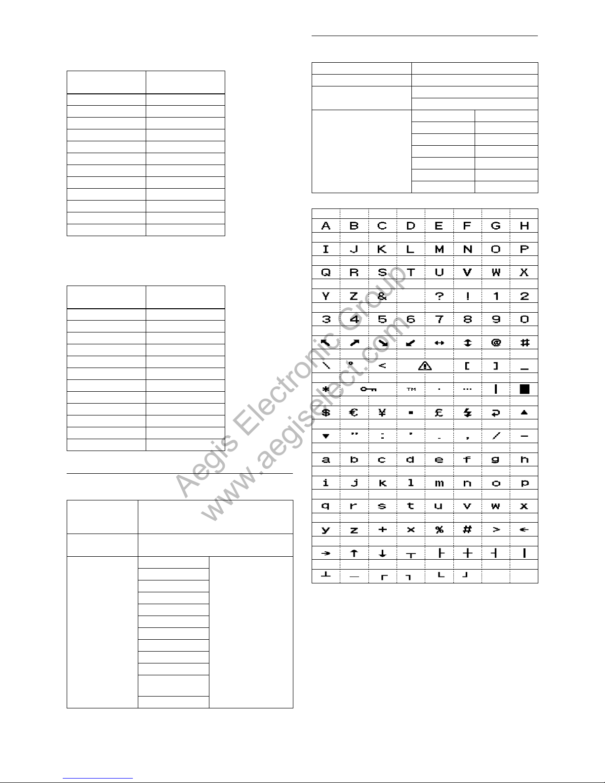
53
Command List
Digital Zoom Combine mode
X12-NTSC/PAL
Digital Zoom
Ratio
Digital Zoom
Position Data
×1 4000
×2 6000
×3 6A80
×4 7000
×5 7300
×6 7540
×7 76C0
×8 7800
×9 78C0
×10 7980
×11 7A00
×12 7AC0
Digital Zoom Separate mode
X12-NTSC/PAL
Digital Zoom
Ratio
Digital Zoom
Position Data
×1 00
×2 80
×3 AA
×4 C0
×5 CC
×6 D5
×7 DB
×8 E0
×9 E3
×10 E6
×11 E8
×12 EB
Lens control
Zoom Position 0000 to 4000 to 7AC0
Wide end Optical Digital
Tele end Tele end
Focus Position
1000 to C000
Far end Near end
Focus Near Limit
1000:O
ver Inf
As the distance on the
left will differ due to
temperature
characteristics, etc., use
as approximate values.
* The lower 1 byte is
fixed at 00.
2000:15m
3000:10m
4000:8m
5000:5m
6000:4m
7000:3.2m
8000:2m
9000:1.5m
A000:1m
B000:30cm
(Initial setting)
C000:1cm
Title setting
Line number
00 to 0A
H-position
00
to 17
Blink
00:
Dose not blink
01: Blinks
Color
00 White
01 Yellow
02 Violet
03 Red
04 Cyan
05 Green
06 Blue
0 01 02 03 04 05 06 07
08 09 0a 0b 0c 0d 0e 0f
10 11 12 13 14 15 16 17
18 19 1a 1b 1c 1d 1e 1f
20 21 22 24 25 26 27
28 29 2a 2b 2c 2d 2e 2f
30 31 32 33 34 35 36 37
38 39 3a 3b 3c 3d 3e 3f
40 41 42 43 44 45 46 47
48 49 4a 4b 4c 4d 4e 4f
50 51 52 53 54 55 56 57
58 59 5a 5b 5c 5d 5e 5f
60 61 62 63 64 65 66 67
68 69 6a 6b 6c 6d 6e 6f
70 71 72 73 74 75 76 77
78 79 7a 7b 7c 7d 7e 7f
23
Aegis Electronic Group
www.aegiselect.com
Page 54
54
Command List
Temperature Reading Conversion Value
(Reference Value)
Reading Value pq
(hex)
Temperature
Conversion
Value (˚C)
00 –3
to +3
0A 7
to 13
14 17
to 23
1E 27
to 33
28 37
to 43
32 47
to 53
3C 57
to 63
Register Setting
When changing the mode, turn the power of the unit
off and on again to confirm the mode.
Register No. Value
VISCA
Baud Rate
00 00
(Initial setting)
9600 bps
01 19200
bps
02 38400
bps
OSD
Language
60 00
(Initial setting)
English
03 Chinese
C
CD Scanning
Mode
72 00
(Initial setting)
Interlaced
01 Progressive
Dig
ital Output
Mode
*
Enabled when
the CCD
Scanning Mode
is Progressive.
73 00
(Initial setting)
72MHz 60p/50p
(Two fields in
the same mode)
01 72MH
z 60p/50p
04 36MH
z 30p/25p
(Stop analog
output)
07 S
top digital
output
Z
oom Limit 50 00
to FF
(Initial
setting: 00)
Wide Limit
(0: Disabled)
51 00
to FF
(Initial
setting: 00)
Tele Limit
(0: Disabled)
E-Zoom Max 52 00
to FF
(Initial
setting: EB)
Max. digital
zoom ratio =
256 ÷
(256-Value)
StableZoom 53 00
(Initial setting)
OFF
01 ON
FocusTrace
@ZoomDirect
54 00 OFF
01
(Initial setting)
ON
FocusOffset
@DomeCover
55 00
to FF
(Initial
setting: 00)
00: None to
FF: Max.
Others
AF Active Time
1)
00 to FF
AF Interval Time
1)
00 to FF
Spot AE X position 00 to 0F
S
pot AE Y position 00 to 0F
R
Gain 00 to FF
B
Gain 00 to FF
A
perture Level 00 to 0F
NR
Level 00 to 05
V-Phase 00 to
020C
(NTSC)
0270 (PAL)
AE Response
01 to 30
A
utoICR ON
O
FF Threshold Level
00 to 1C
MD
Threshold Level 00 to FF
MD
Interval Time
1)
00 to FF
MD Set Horizontal Position 00 to 0C
MD
Set Vertical Position 00 to 08
C
olor Enhancement
Threshold Level
00
to 7F
C
olor Enhancement
Hysteresis Width
00 to 7F
C
olor Enhancement
Fixed Color Y
00 to 7F
C
olor Enhancement
Fixed Color Cr
2)
00 to 7F
Color Enhancement
Fixed Color Cb
2)
00 to 7F
1)
Unit: One second
2)
40 center
Aegis Electronic Group
www.aegiselect.com
Page 55

55
Specifications
Specifications
FCB-EX2700/P
Picture elements FCB-EX2700: Approx. 480K pixels
FCB-EX2700P
: Approx. 570K pixels
Horizontal resolution
670 TV lines (WIDE end, Typical
value)
Lens 40×
zoom
F= 3.06 mm (WIDE) to 122.4 mm
(TELE), F1.6 to F4.6
Zoom movement speed
(NT
SC)
Optical WIDE/Optical TELE
3.5 sec (Focus Tracking ON)
1.9 sec (Focus Tracking OFF)
Optical WIDE/Digital TELE
5.5 sec (Focus Tracking ON)
1.9 sec (Focus Tracking OFF)
Digital WIDE/Digital TELE
2.0 sec
(P
AL)
Optical WIDE/Optical TELE
3.5 sec (Focus Tracking ON)
1.9 sec (Focus Tracking OFF)
Optical WIDE/Digital TELE
6.0 sec (Focus Tracking ON)
1.9 sec (Focus Tracking OFF)
Digital WIDE/Digital TELE
2.5 sec
Focus Movement time
∞
to Near
1.0 sec
Digital zoom 12×
(480× with optical zoom)
Angle of view (H)
Approx. 60 degree (WIDE end) to
Approx. 1.6 degree (TELE end)
Min. working distance
10 mm (WIDE end), 1500 mm
(TELE end)
Sync system Internal/External (V-Lock)
Min. illumination
(F1.6, 50 IRE) 0.6 lx/1/60 sec (NTSC), 1/50 sec
(PAL) (Typical value)
0.04 lx/1/4 sec (NTSC), 1/3 sec
(PAL) (Typical value)
ICR-ON Mode
0.01 lx/1/4 sec (NTSC),
1/3 sec (PAL) (Typical value)
Recommended illumination
100 lx to 100,000 lx
S/N ratio 50 dB (Weight ON)
Back light compensation
O
N/OFF
Electronic shutter speed
1/1 sec to 1/10000 sec (22 steps)
White balance AUTO, ATW, Indoor, Outdoor, One
Push WB, Manual WB, Outdoor
Auto, Sodium Vapor Lamp (Fix/
Auto)
Ga
in Auto/Manual
(–3 to +28, 16 steps)
Max. Gain Limit
(6 to 28, 12 steps)
Wide dynamic range
WD Mode/VE Mode/OFF
3D noise reduction
ON/OFF (level 5 to 1 / OFF, 6 steps)
Image Stabilizer ON/OFF/HOLD
Defog mode On/Off
Color Enhancement
O
N/OFF
Aperture control 16 steps
Preset 6-POSITIONS
S
erial interface VISCA protocol (CMOS 5V)
9.6 Kbps, 19.2 Kbps, 38.4 Kbps, Stop
bit, 1 bit
Video Output VBS: 1.0 Vp-p (Sync negative),
Y/C Output
Digital (ITU-R BT656 equiv.)
Progressive/Interlace
Storage temperature/Humidity
–20
˚C to +60 ˚C (–4 ˚F to +
140 ˚F)/20%
to 95%
Absolute humidity: 36 g/m
3
Operating temperature/Humidity
–5
˚C to +60 ˚C (23 ˚F to +140 ˚F)/
20% to 80%
Absolute humidity: 36 g/m
3
Power requirements/Power consumption
6 V to 12 V DC/2.4 W (during motor
operation: 3.2 W)
Mass Approx. 265 g (8.6 oz.)
Aegis Electronic Group
www.aegiselect.com
Page 56
56
Specifications
Dimensions 50.0 × 60.0 × 90.9 mm
(19
3
/4× 23 5/8 × 35 7/8 in.) (w/h/d)
Design and specifications are subject to change without
notice.
Digital Output Function
Operation Mode Digital Output (ITU-R BT656 equiv.)
Interlace 60i/50i
, clock rate: 36 MHz
Interlace WD
Progressive 60p/50p
, clock rate: 72 MHz
60p/50p (30p/25p ×
2), clock rate: 72 MHz
30p/25p, clock rate: 36 MHz
Progressive WD 60p/50p (30p/25p
×
2), clock rate: 72 MHz
Slow shutter is not available in the Interlace WD or Progressive WD mode.
Digital Output Characteristics
DC characteristics
ITEM SIGN Rating Value UNIT
MIN MAX
O
utput voltage Digtal Signal out [7] to [0]
Digital Clock
VOH1 2.58 V
VOL1 0.4 V
AC characteristics
MODEL MODE ITEM SIGN Typ
FCB-EX2700 (NTSC) Interlace C
lock cycle period tcyc (ns) 27.8
Data output setup time tsu (ns) 11.3
D
ata output hold time thd (ns) 12.3
Progressive C
lock cycle period tcyc (ns) 13.9
Data output setup time tsu (ns) 4.64
D
ata output hold time thd (ns) 5.36
FCB-EX2700P
(PAL) Interlace C
lock cycle period tcyc (ns) 27.8
Data output setup time tsu (ns) 11.5
D
ata output hold time thd (ns) 12.4
Progressive C
lock cycle period tcyc (ns) 13.9
Data output setup time tsu (ns) 4.4
D
ata output hold time thd (ns) 5.48
Aegis Electronic Group
www.aegiselect.com
Page 57
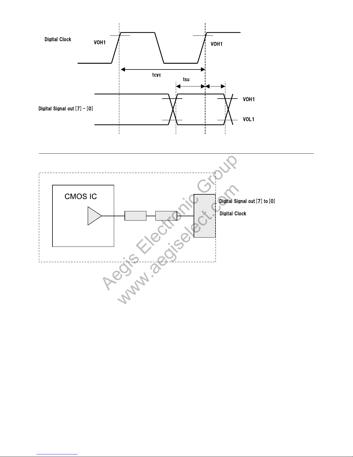
57
Specifications
FCB Interior – Digital Output
Connector
Ferrite
Beads
Resistor
Aegis Electronic Group
www.aegiselect.com
Page 58
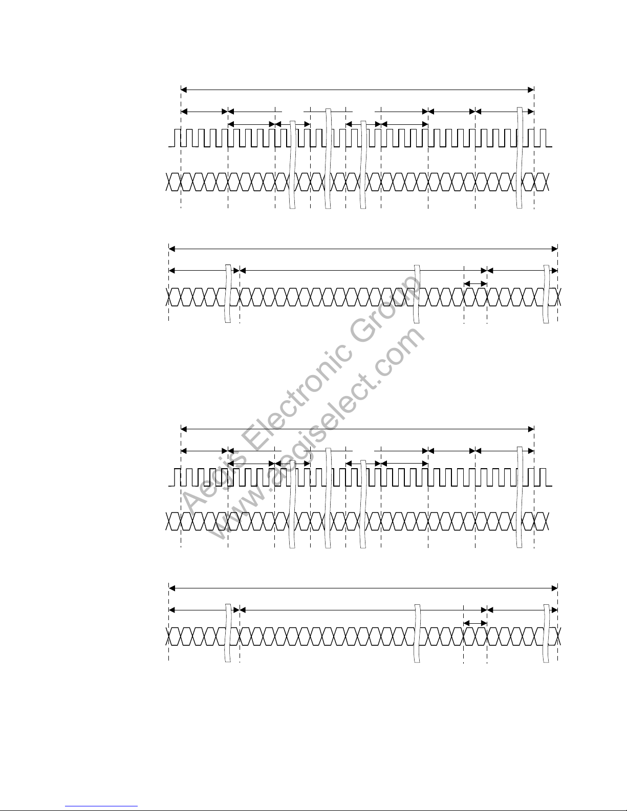
58
Specifications
FCB-EX2700P
Digital Output Timing [50p mode]
Data out [0-7]
CLK [72 MHz]
Horizontal
Vertical
Data out [0-7]
4CLK
SAV
4CLK
Black data
4CLK
Black data
1952CLK Effective pixel
1H = 2304CLK
4CLK
EAV
344CLK
BLK
625H
24H
BLK
582H Effective line
BLK : Black data (Y 10, Cb/Cr 80)
19H2H
BLK
Cr0
Y1
Cb0
Y0
Cr1
Y3
Cb1
Y
Cb
Y
Cr
Y
Cb
Y
Black data
32CLK
Ignored area
24CLK
Ignored area
FCB-EX2700P
Digital Output Timing [25p mode]
Data out [0-7]
CLK [36 MHz]
Horizontal
Vertical
Data out [0-7]
4CLK
SAV
4CLK 4CLK
Black data Black data
1952CLK Effective pixel
1H = 2304CLK
4CLK
EAV
344CLK
BLK
625H
24H
BLK
582H Effective line
19H
BLK
2H
BLK : Black data (Y 10, Cb/Cr 80)
Cr0
Y1
Cb0
Y0
Cr1
Y3
Cb1
CbYY
Cr
Y
Cb
Y
Black data
32CLK
Ignored area
24CLK
Ignored area
Aegis Electronic Group
www.aegiselect.com
Page 59
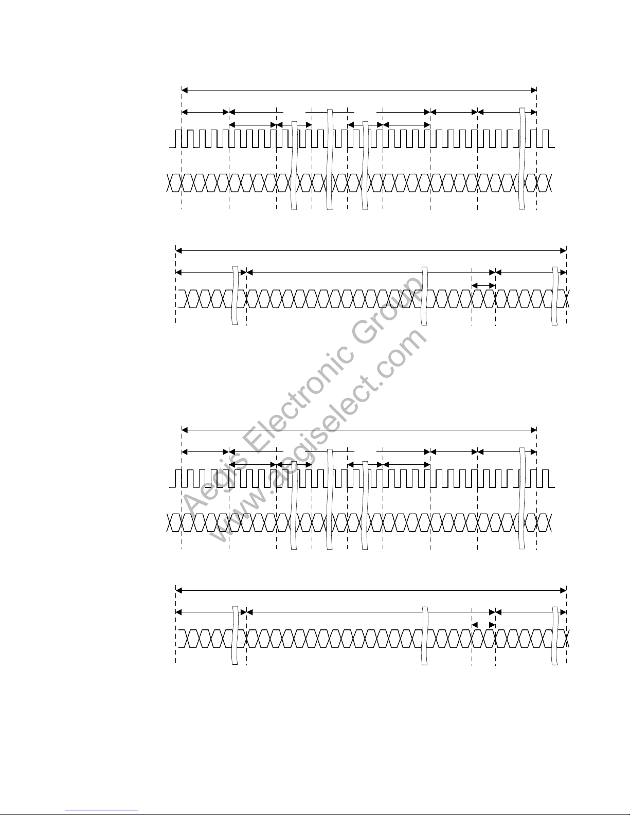
59
Specifications
FCB-EX2700
Digital Output Timing [60p mode]
Data out [0-7]
Horizontal
Vertical
Data out [0-7]
CLK [72 MHz]
4CLK
SAV
4CLK
Black data
4CLK
Black data
1952CLK Effective pixel
1H = 2288CLK
4CLK
EAV
328CLK
BLK
Cr0
Y1
Cb0
Y0
Cr1
Y3
Cb1
Y
Cb
Y
Cr
Y
Cb
Y
525H
20H
BLK
494H Effective line
11H
BLK
2H
Black data
BLK : Black data (Y 10, Cb/Cr 80)
36CLK
Ignored area
28CLK
Ignored area
FCB-EX2700
Digital Output Timing [30p mode]
Data out [0-7]
Horizontal
Vertical
Data out [0-7]
CLK [36 MHz]
4CLK
SAV
4CLK
Black data
4CLK
Black data
1952CLK Effective pixel
1H = 2288CLK
4CLK 328CLK
BLK
525H
20H
BLK
494H Effective line
11H
BLK
2H
Black data
BLK : Black data (Y 10, Cb/Cr 80)
EAV
Cr0
Y1
Cb0
Cr1
Y3
Cb1
Y
Cb
Y
Cr
Y
Cb
Y
Y0
36CLK
Ignored area
28CLK
Ignored area
Aegis Electronic Group
www.aegiselect.com
Page 60
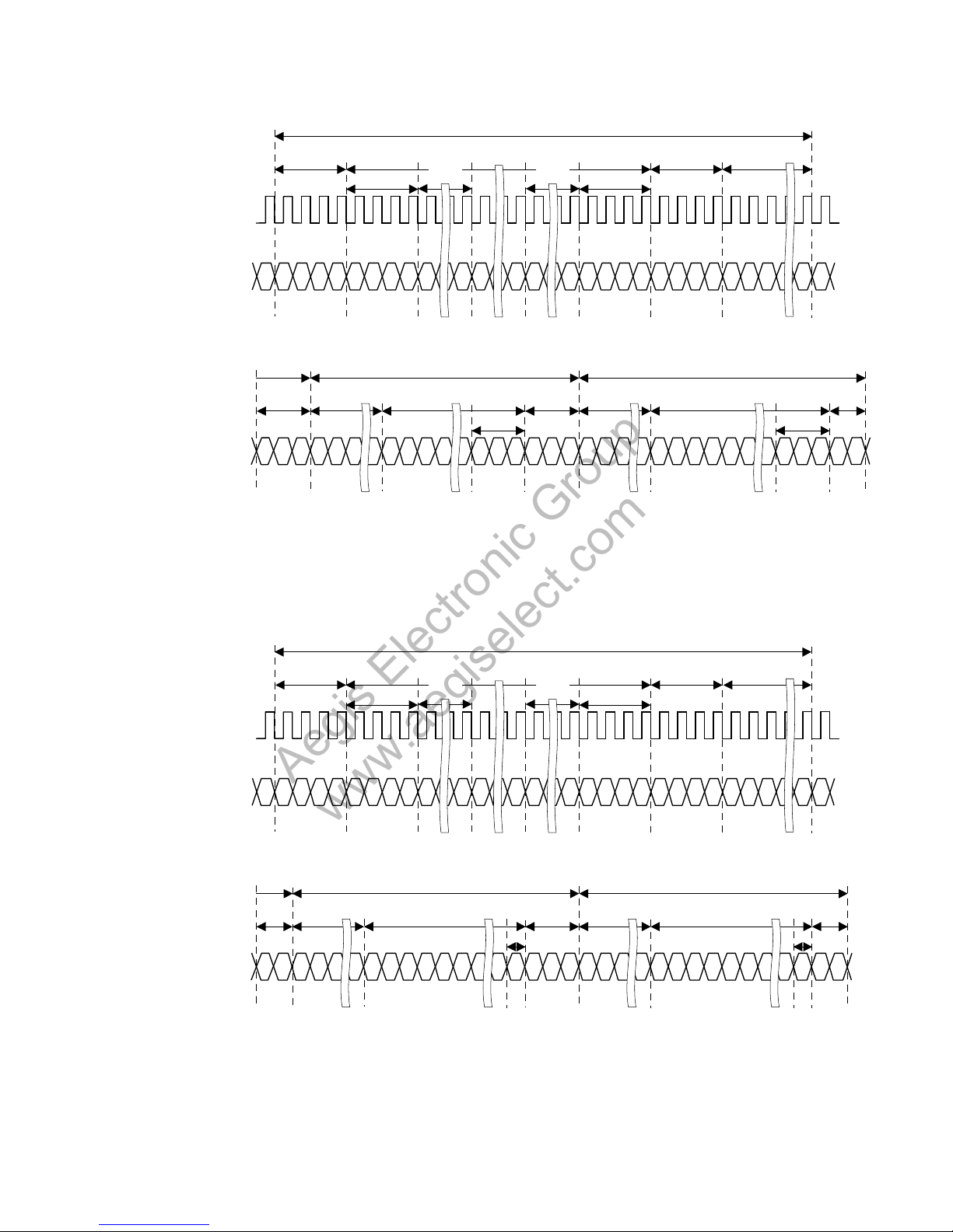
60
Specifications
FCB-EX2700
Digital Output Timing [60i mode]
Data out [0-7]
Horizontal
Vertical
Data out [0-7]
CLK [36 MHz]
4CLK
SAV
4CLK
Black data
4CLK
Black data
1952CLK Effective pixel
1H = 2288CLK
4CLK
EAV
328CLK
BLK
Cr0
Y1
Cb0
Y0
Cr1
Y3
Cb1
Y
Cb
Y
Cr
Y
Cb
Y
FLD1 ODD LINE FLD2 EVEN LINE
13H
247H Effective line
2H
2H
3H 13H
247H Effective line
FLD2
BLKBLK BLK
3H
Black data
BLK
3H
Black data
BLK
BLK : Black data (Y 10, Cb/Cr 80)
36CLK
Ignored area
28CLK
Ignored area
FCB-EX2700P
Digital Output Timing [50i mode]
Data out [0-7]
CLK [36 MHz]
Horizontal
Vertical
Data out [0-7]
4CLK
SAV
4CLK
Black data
4CLK
Black data
1952CLK Effective pixel
1H = 2304CLK
4CLK
EAV
344CLK
BLK
FLD1 ODD LINE FLD2 EVEN LINE
19H
BLK
291H Effective line
2H
BLK
2H1H
BLK
Black data
1H
Black data
3H
BLK
19H
BLK
291H Effective line
FLD2
BLK : Black data (Y 10, Cb/Cr 80)
Cr0
Y1
Cb0
Y0
Cr1
Y3
Cb1
Y
Cb
Y
Cr
Y
Cb
Y
32CLK
Ignored area
24CLK
Ignored area
Aegis Electronic Group
www.aegiselect.com
Page 61

61
Specifications
DIGITAL Image Output Y, Cr, Cb 4:2:2 FORMAT
Aegis Electronic Group
www.aegiselect.com
Page 62
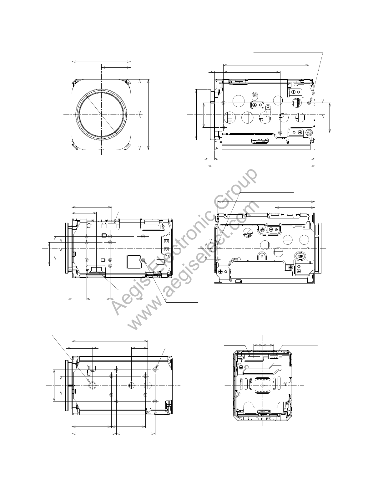
62
Specifications
Dimensions
2-M2
4-M2
CN500 4P
Y/C
CN501 9P
33.95
20.95
12.55
ø43
(ø43)
(30)
60
30
9-M2
7.5
(5.4)
85.45
90.9
50
25
20 ±0.1
20 ±0.1 28 ±0.1
20 ±0.1
5
CN200 12P
CN702 12P
8-M2
64.55
17.55 14
±0.1
16 ±0.1
27 ±0.1
33.55
37.75
29 ±0.1
33 ±0.1
48.3 ±0.1
73 ±0.1
21 ±0.1
25.4 ±0.1
10
82.75
(33.95)
14 ±0.1
4.5
9.57.5
Front Right side
Top Left side
1/4-20UNC (Tripod screw for camera)
Within a depth of 7 mm (
9
/32 in.) or
less from the bottom surface
Within a depth of 3 mm
(
1
/8 in.) or less from the
bottom surface
Within a depth of 3 mm (
1
/8 in.)
or less from the side
Digital output
Bottom Back
Within a depth of 3 mm
(
1
/8 in.) or less from the
top surface
Within a depth of 3 mm (
1
/8 in.)
or less from the side
Unit: mm (inches)
Aegis Electronic Group
www.aegiselect.com
Page 63
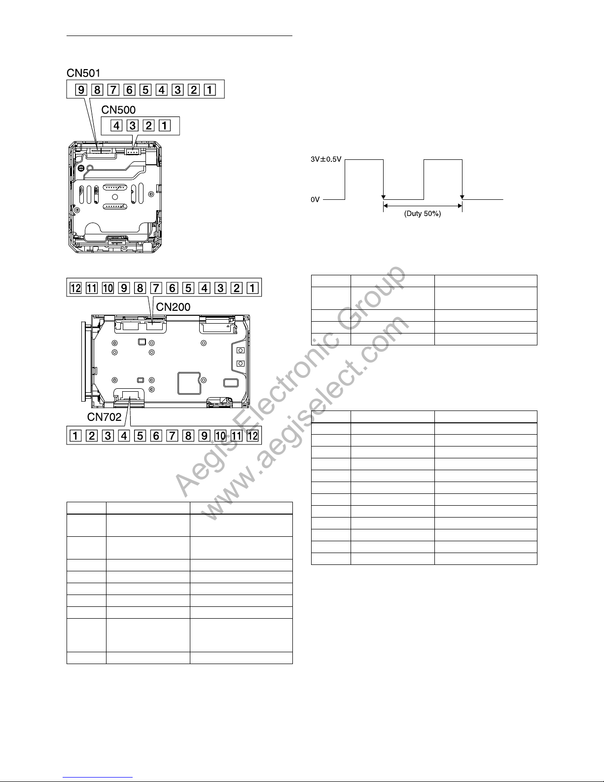
63
Specifications
Pin assignment
CN501
KYOCERA ELCO Co. 00 6200 509 130 000+
Pin No. Name Level
1 RxD CM
OS 5 V (low: max 0.8 V,
high: min 2.0 V) Read Data
2 TxD CM
OS 5 V (low: max 0.1 V,
high: min 4.4 V) Send Data
3 GND
(for RxD&TxD)
4 D
C IN 9.0 V±3 V
5 GND
(for DC IN)
6 VBS
OUT 1.0 V±0.2 V
7 GND
(for VBS OUT)
8 V
LOCK PULSE External VD-Lock Pulse
(EX.FV: Negative, 3 Vp-p
50% duty)
9 GND
(VL PULSE)
Frequency: 60 Hz ±1 Hz (NTSC)
50 Hz ±1 Hz (PAL)
Amplitude: 3 V ±0.5 V square wave (50% duty)
CMOS level
V Phase Adjustment Range:
0˚ to 360˚ from V SYNC falling edge
Recommended Input Waveform
CN500
J.S.T. Mfg Co. S4B-ZR-SM4A-TF(LF)
Pin No. Name Level
1 Y_Out 1.0
Vp-p (75 ohm),
luminance signal
2 GND
(for Y signal)
3 C_Out C
hrominance signal
4 GND
(for C signal)
CN702
KYOCERA ELCO Co. 086222012101848+
Pin No. Name Level
1 GND
2 GND
3 KE
Y AD0
4 KE
Y AD1
5 KE
Y AD2
6 KE
Y AD3
7 KE
Y AD4
8 KE
Y AD5
9 KE
Y AD6
10 KE
Y AD7
11 NC
12 Strobe
Aegis Electronic Group
www.aegiselect.com
Page 64
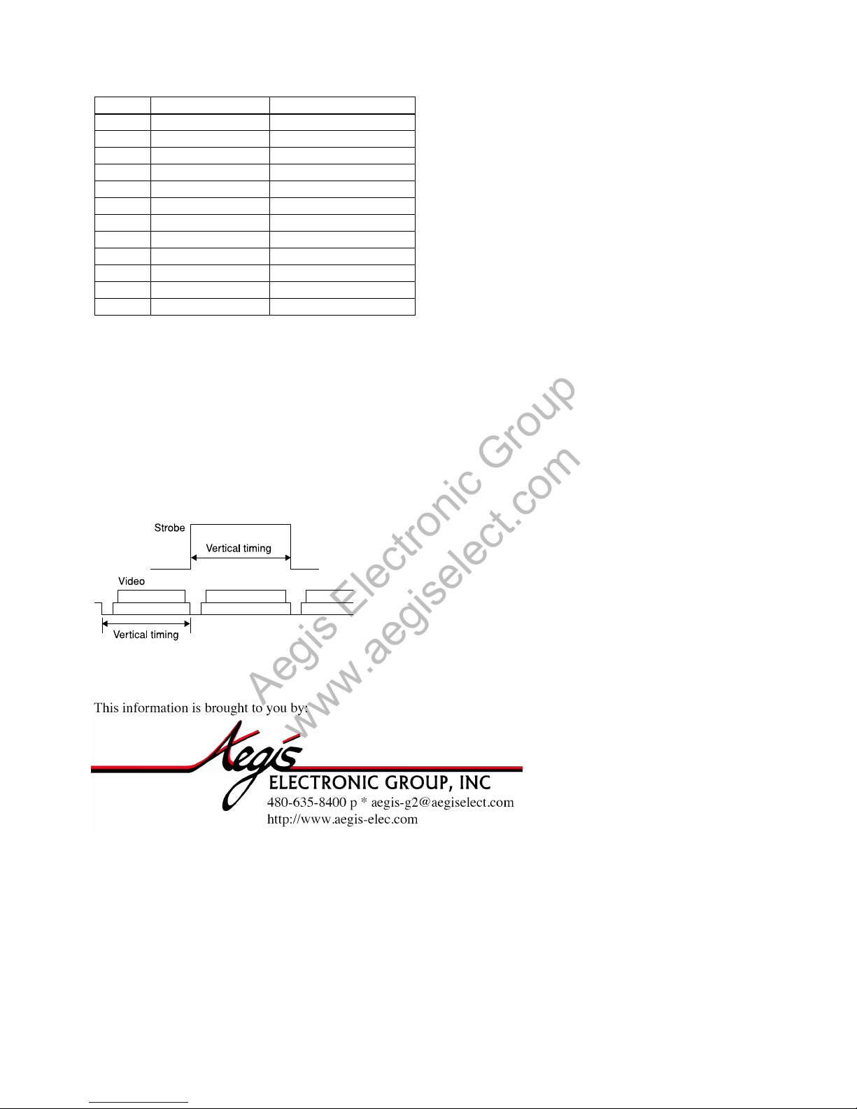
64
Specifications
CN200
KYOCERA ELCO Co. 086222012101848+
Pin No. Name Level
1 GND
2 Dig
ital Out 0 0 - 3.3 Vp-p
3
Digital Out 1 0 - 3.3 Vp-p
4
Digital Out 2 0 - 3.3 Vp-p
5
Digital Out 3 0 - 3.3 Vp-p
6
Digital Out 4 0 - 3.3 Vp-p
7
Digital Out 5 0 - 3.3 Vp-p
8
Digital Out 6 0 - 3.3 Vp-p
9
Digital Out 7 0 - 3.3 Vp-p
10
GND
11 CLOCK 0
- 3.3 Vp-p
12 GND
(Precaution when using digital output)
Im
age noise may occur when using digital output.
Take measures against the noise such as shielding FFC to be
connected and attaching a ferrite core or an electromagnetic
suppression sheet to FFC as needed. The recommended maximum
FFC length is 100 mm or less. Also, firmly ground and connect the
frame so as not to cause the ground potential difference with the
connection destination. Noise may occur due to the ground
potential difference.
Strobe signal specifications
Aegis Electronic Group
www.aegiselect.com
 Loading...