

Sony FCB-EV7520A, FCB-CV7520A Technical Manual
D-023-100-11(1)
Color Camera Module
Technical Manual
FCB-EV7520A
FCB-CV7520A
2018 Sony Corporation

Table of Contents
Features ............................................................................. 3
Precautions ....................................................................... 4
Locations of Controls .......................................................5
Basic Functions ................................................................. 6
Overview of Functions ..................................................................... 6
User’s Updating ............................................................................... 20
Eclipse ................................................................................................. 23
Spectral Sensitivity Characteristics .......................................... 23
Initial settings and backup of camera ..................................... 24
Mode Condition .............................................................................. 26
Command List .................................................................29
VISCA/RS-232C Commands ........................................................ 29
FCB Camera Commands .............................................................. 35
Specifications ................................................................. 56
2

• Imager
This camera uses a 1/2.8" “Exmor R” CMOS
(complementary metal-oxide semiconductor) image
sensor (approx. 2.13 million effective pixels) that
supports FULL HD (high definition) to produce highquality images.
Overview
Features
• ISP
Using the image signal processor (ISP), the following
images can be obtained.
- Full HD 60fps output image
- Low focal plane distortion image using the
high-speed readout of imager
The following functions are provided.
- Noise Reduction (NR), and Image Stabilizer
functions
- Wide Dynamic Range Mode (Wide-D), Tone
correction (Visibility Enhancer), and Defog
functions
• Lens
The camera is equipped with a bright lens with 30×
optical zoom and F1.6 aperture.
With consideration given environmental protection,
this module is designed to operate with low power
consumption and also incorporates lead-free and
halogen-free circuit boards.
3

Overview
Precautions
Software
Use of the demonstration software developed by Sony
Corporation or use of the software with customer
developed application software may damage hardware,
the application program or the camera. Sony
Corporation is not liable for any damages under these
conditions.
Operation
Start the camera control software on your computer
after you turn on the camera and the image is displayed.
Operation and storage locations
Do not shoot images that are extremely bright (e.g.,
light sources, the sun, etc.) for long periods of time. Do
not use or store the camera in the following extreme
conditions:
• Extremely hot or cold places (operating temperature
–5 ˚C to +60 ˚C (23 ˚F to 140 ˚F))
• Close to generators of powerful electromagnetic
radiation such as radio or TV transmitters
• Where it is subject to fluorescent light reflections
• Where it is subject to unstable (flickering, etc.)
lighting conditions
• Where it is subject to strong vibration
• Where it is subject to radiation from laser beams
Care of the unit
Remove dust or dirt on the surface of the lens with a
blower (commercially available).
Other
• Design and specifications are subject to change
without notice.
• Do not apply excessive voltage. (Use only the specified
voltage.) Otherwise, you may get an electric shock or
a fire may occur.
• The CMOS image sensor and IC included in this
camera may break if exposed to static electricity.
When directly handling this camera, wear an
antistatic strap, spread a conductive sheet or similar
item under your workbench, and take measures to
eliminate static electricity.
• In case of abnormal operation, contact your
authorized Sony dealer or the store where you
purchased the product.
Phenomena specific to CMOS image sensors
The following phenomena that may appear in images
are specific to CMOS image sensors. They do not
indicate malfunctions.
Rolling shutter
As CMOS image sensors use shutters that capture
images line-by-line, there is a slight time difference
between the top and bottom of an image. As a result,
images may appear skewed if the camera is moved.
White flecks
Although the CMOS image sensors are produced with
high-precision technologies, fine white flecks may be
generated on the screen in rare cases, caused by cosmic
rays, etc.
This is related to the principle of CMOS image sensors
and is not a malfunction.
The white flecks especially tend to be seen in the
following cases:
• when operating at a high environmental temperature
• when you have raised the master gain (sensitivity)
• when operating in Slow-Shutter mode
Aliasing
When fine patterns, stripes, or lines are shot, they may
appear jagged or flicker.
Phenomena Specific to Lenses
Ghosting
If a strong light source (e.g., the sun) exists near the
incidence angle of the lens, bright spots may appear in
the image due to diffuse reflection within the lens.
About the trademark
“Exmor R” and “StableZoom” are trademarks of Sony
Corporation.
4
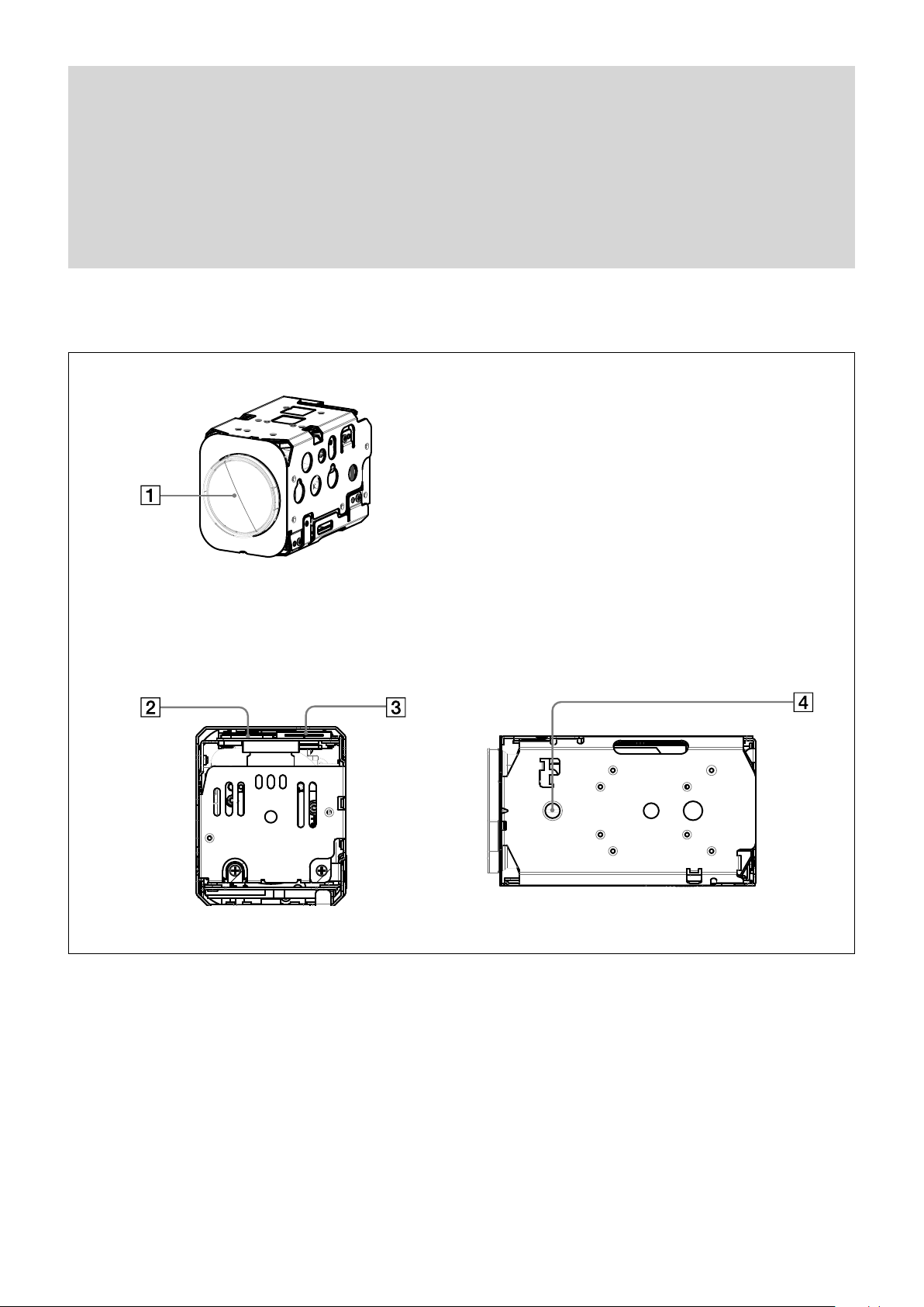
Front
Locations of Controls
Locations of Controls
Back
Lens
Digital output connector
Maintenance connector
* Do not connect here, this is for maintenance purpose.
Tripod screw hole
When a tripod is used, please use 7 mm (
Also, please be sure to attach the tripod securely.
9
/32 in.) or less screw to attach it to the camera.
Bottom
5
Basic Functions
Basic Functions
Overview of Functions
The camera control is performed by VISCA
Commands.
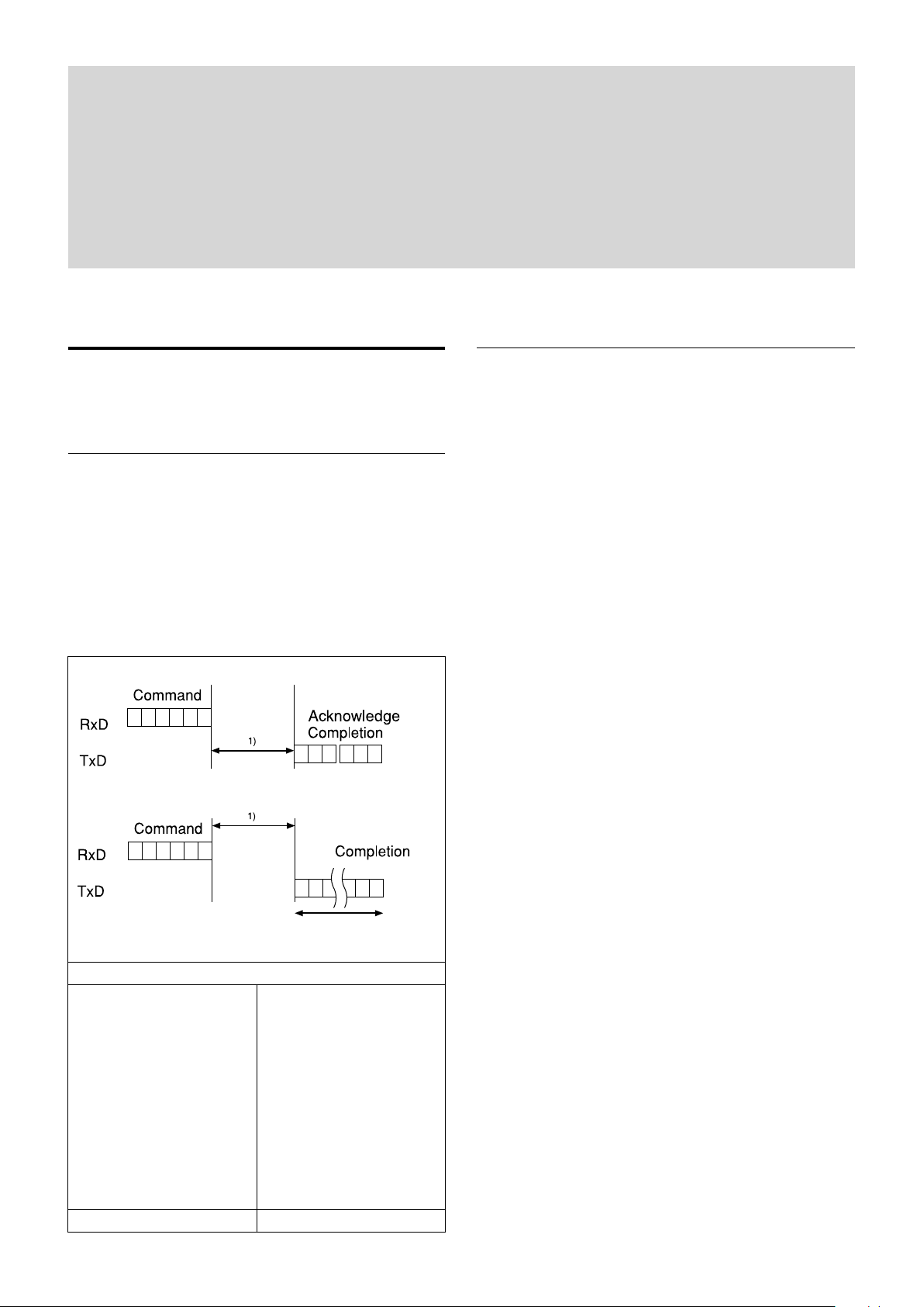
Timing Chart
As VISCA Command processing can only be carried
out one time in a Vertical cycle, it takes the maximum
1V cycle time for an Acknowledge/Completion to be
returned.
If the Command/Acknowledge/Completion
communication time can be less than the 1V cycle
time, then every 1V cycle can receive a Command.
General Commands
Query Commands
In general
• Power On/Off (Standby)
Powers the camera on and off.
When the power is off (on Standby), the camera is
able to accept the VISCA Commands although the
screen is set non-displayed.
• I/F Clear
Clears the Command buffer of the FCB camera.
• Address Set
VISCA is a protocol, which normally supports a daisy
chain of up to seven connected cameras via RS-232C
interface. In such cases, the address set command can
be used to assign addresses from 1 to 7 to each of the
seven cameras, allowing you to control the seven
cameras with the same personal computer.
Although the FCB camera does not support direct
connection of cameras in a daisy chain, be sure to use
the address set command to set the address whenever
a camera is connected for the first time.
• ID Write
Sets the camera ID.
16 Byte
1) 1V cycle times on each Monitoring Mode and Shutter Speed.
Monitoring Mode
1080p/60 1080p/50
1080p/59.94 1080p/25
1080p/30 1080i/50
1080p/29.97 720p/50
1080i/60 720p/25
1080i/59.94
720p/60
720p/59.94
720p/30
720p/29.97
1/60 sec 1/50 sec
• Mute
Blanks the screen and sends out a synchronizing
signal.
• Lens Initialize
Initializes the zoom and focus of the lens. Even when
power is turned on, it initializes the zoom and the
focus.
6

Basic Functions
Zoom
The zoom function contains 2 functions, optical zoom
and digital zoom.
• Optical zoom
The function to zoom optically by moving the zoom
lens to change focus distance.
This can zoom up to 30×.
• Digital zoom
The function to zoom images digitally by cropping the
center part of captured images to zoom with the CMOS
image sensor.
When the zoom diameter goes up, the resolution will
go down. This can zoom up to 12×.
By combining the optical zoom and digital zoom, the
unit can zoom up to 360×.
Zoom has the following modes.
Using Standard Mode
Using Variable Mode
There are eight levels of zoom speed.
Notes
• The zoom will be stopped when a Stop Command is sent
after the zoom operation is started in Standard Mode or
Variable mode. If you do not send a Stop Command, the
zoom will be stopped after reaching the Wide end or the
Tele end.
• Direct Mode cannot be operated while zooming in
Standard Mode or Variable Mode.
Operate Direct Mode after Stop Command.
Direct Mode
Setting the zoom position enables quick
movement to the designated position.
Digital Zoom
The Zoom Mode supports, a OFF, a Combined
Mode and a Separate Mode.
Combined Mode
This is the previously existing zoom method.
After the optical zoom has reached its
maximum level, the camera switches to Digital
Zoom Mode.
Separate Mode
In this mode, Optical Zoom and Digital Zoom
can be operated separately.
You can use digital zoom magnification at any
time from within any level of optical
magnification.
Note
When you operate Direct Mode Digital Zoom
When the Digital Zoom is operated in the Direct
Mode, the Direct Zoom Position of the Inquiry
Command is not immediately reflected.
Place a wait time before reading the position.
When using the Slow Shutter, place a wait time more
than twice the shutter speed.
When not using Slow Shutter, place a wait time of 0.1
seconds or more.
About Continuous Zoom Position Reply
With ZoomDirect mode, or when zooming according
to a preset, the camera outputs zoom position data
when Continues Zoom Position Reply is set to On via a
command.
Continues Zoom Position Reply: y0 07 04 69 0p 0p 0q
0q 0q 0q FF
pp: D-Zoom Position
qqqq: Zoom Position
Focus
Focus has the following modes.
• Auto Focus Mode
The minimum focus distance is 10 mm at the optical
Wide end and 1200 mm at the optical Tele end, and is
independent of the digital zoom. The Auto Focus
(AF) function automatically adjusts the focus position
to maximise the high frequency content of the picture
in a center measurement area, taking into
consideration the high luminance and strong contrast
components.
- Normal AF Mode
This is the normal mode for AF operations.
- Interval AF Mode
The mode used for AF movements carried out at
particular intervals. The time intervals for AF
movements and for the timing of the stops can be
set in one-second increments using the Set Time
Command. The initial setting for both is set to
5 seconds.
- Zoom Trigger Mode
When zoom position is changed, it becomes AF
mode during the pre-set value (initial setting is set
to 5 seconds). Then it stops.
• AF Sensitivity
The switching of AF sensitivity can be set.
- Normal
Reaches the highest focus speed quickly. Use this
when shooting a subject that moves frequently.
Usually, this is the most appropriate mode.
- Low
Improves the stability of the focus. When the
lighting level is low, the AF function does not take
effect, even though the brightness varies,
contributing to a stable image.
7

Basic Functions
• Manual Focus Mode
Manual Focus has both a Standard Mode and a
Variable Mode. Standard Mode focuses at a fixed rate
of speed. Variable Mode has eight speed levels.
Note
In these standard and variable modes, it is necessary to send Stop
Command to stop the zoom operation.
• One push AF
When sending a One Push Trigger command in
Manual Focus Mode, the lens moves to focus on the
subject. After that, it will convert to the normal
Manual Focus Mode.
There are two kinds of One Push Trigger commands.
- One Push Trigger
As with the Auto Focus, move the focus smoothly
and focus on the subject.
- Full Scan One Push Trigger
Perform a Full Scan (move the focus to the whole
area from the Near end to the Far end), and focus
on the subject after confirming the distance with
the subject.
Unlike the One Push Trigger, the time to focus is
longer because of full scan operation, but you can
focus more accurately.
One Push White Balance data is lost when the power
is turned off. If the power is turned off, reset One
Push White Balance.
• Manual WB
This is a mode that enables you to manually set the
control of R and B gain up to 256 steps.
• Outdoor Auto
This is an auto white balance mode specifically for
outdoors. It allows you to capture images with natural
white balance in the morning and evening.
• Sodium Vapor Lamp Auto
This is an auto white balance mode that is compatible
with sodium vapor lamps.
• Sodium Vapor Lamp
This is a fixed white balance mode specifically for
sodium vapor lamps.
• Sodium Vapor Lamp Outdoor Auto
This is an auto white balance mode specifically for
outdoors, which is compatible with sodium vapor
lamps.
Note
High-pressure sodium lamps are supported. Proper white balance
may not be captured for some subjects when using low-pressure
sodium lamps.
• Near Limit
Can be set in a range from 1000 (∞) to F000 (10 mm).
Initial setting: D000h (30 cm)
White Balance (WB)
White Balance has the following modes.
• Auto
This mode computes the white balance value output
using color information from the entire screen. It
outputs the proper value using the color temperature
radiating from a black subject based on a range of
values from 2500K to 7500K.
This mode is the initial setting.
• ATW
Auto Tracing White balance (2000K to 10000K)
• Indoor
3200K Base Mode
• Outdoor
5800K Base Mode
• One Push WB
The One Push White Balance mode is a fixed white
balance mode that may be automatically readjusted
only at the request of the user (One Push Trigger),
assuming that a white subject, in correct lighting
conditions, and occupying more than 1/2 of the
image, is submitted to the camera.
Auto Exposure Mode (AE)
A variety of AE functions are available for optimal
output of subjects in lighting conditions that range
from low to high.
• Full Auto
Iris, Gain and Shutter Speed can be set automatically.
• Gain Limit Setting
The gain limit can be set at the Full Auto, Shutter
Priority, Iris Priority, Spot Exposure and Manual in
the AE mode. Use this setting when you want to
obtain image in which signal-to-noise ratio is
particularly important.
• Shutter Priority
Adjust with Variable Shutter Speed (1/1 to 1/10,000
sec., 16 high-speed shutter speeds plus 6 low-speed
shutter speeds), Auto Iris and Gain.
• Iris Priority
Adjust with Variable Iris (F1.6 to Close, 14 steps),
Auto Gain and Shutter speed.
• Manual
Adjust with Variable Shutter, Iris and Gain.
8
Basic Functions
(8,7)
Horizontal 17
Vertical 15
0
0
1
2
3
4
5
6
7
8
9
A
B
C
D
E
1 2 3 4 5 6 7 8 9 A B C D E F 10
AE – Shutter Priority
The shutter speed can be set freely by the user to a total
of 22 steps – 16 high speeds and 6 low speeds. When
the slow shutter is set, the speed can be adjusted
according to subject brightness. The picture output is
read at a normal rate from the memory. The memory is
updated at a low rate from the CMOS. AF following
capability is lowered and also the number of frame to
be displayed is decreased. In high speed mode, the
shutter speed can be set up to 1/10,000s. The iris and
gain are set automatically, according to the brightness
of the subject.
Data 59.94/29.97
mode
15 1/10000 1/10000
14 1/6000 1/6000
13 1/4000 1/3500
12 1/3000 1/2500
11 1/2000 1/1750
10 1/1500 1/1250
0F 1/1000 1/1000
0E 1/725 1/600
0D 1/500 1/425
0C 1/350 1/300
0B 1/250 1/215
0A 1/180 1/150
09 1/125 1/120
08 1/100 1/100
07 1/90 1/75
06 1/60 1/50
05 1/30 1/25
04 1/15 1/12
03 1/8 1/6
02 1/4 1/3
01 1/2 1/2
00 1/1 1/1
50/25 mode
AE – Manual
The shutter speed (22 steps), iris (14 steps) and gain
(15 steps) can be set freely by the user.
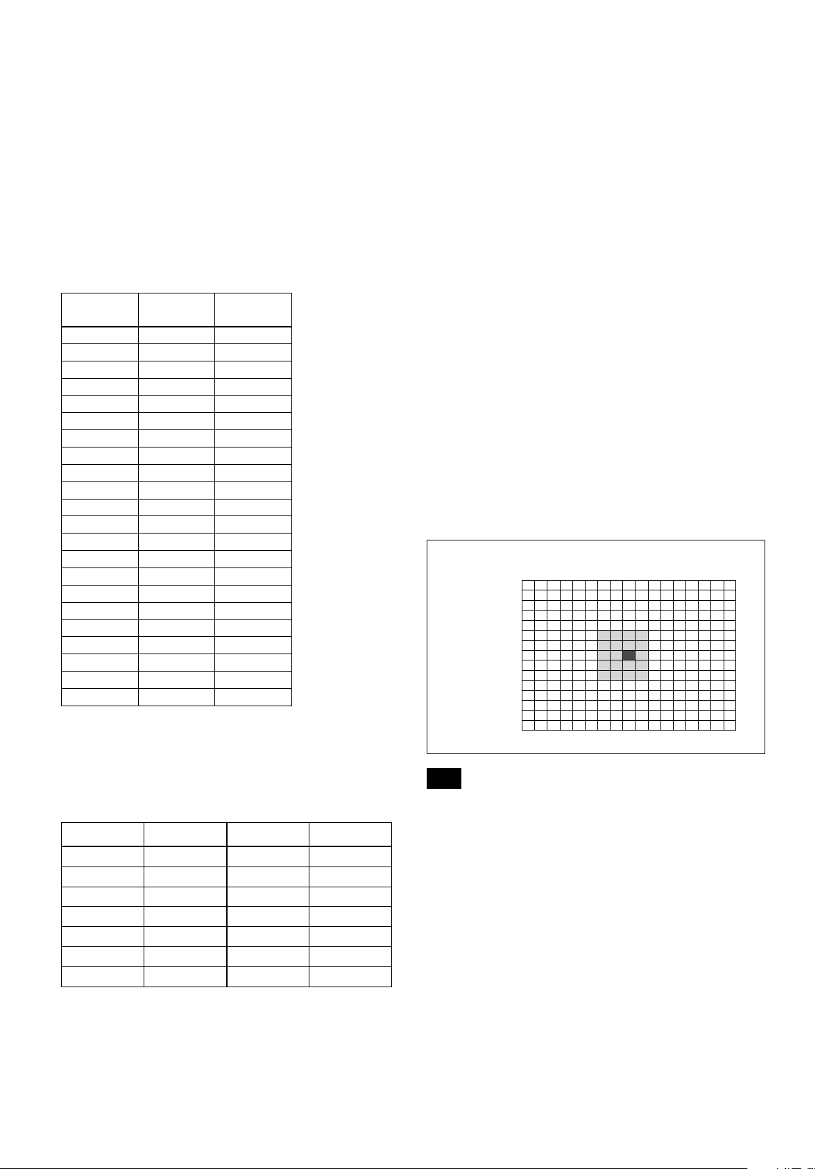
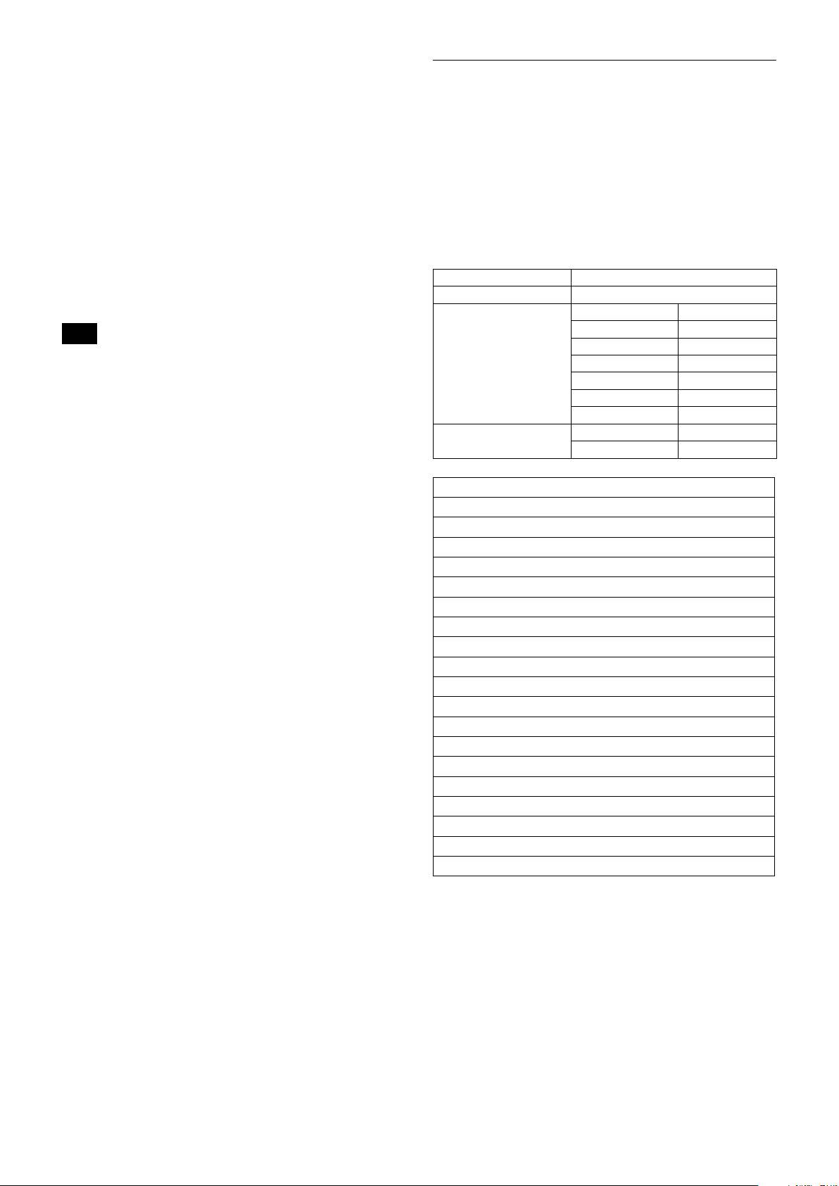
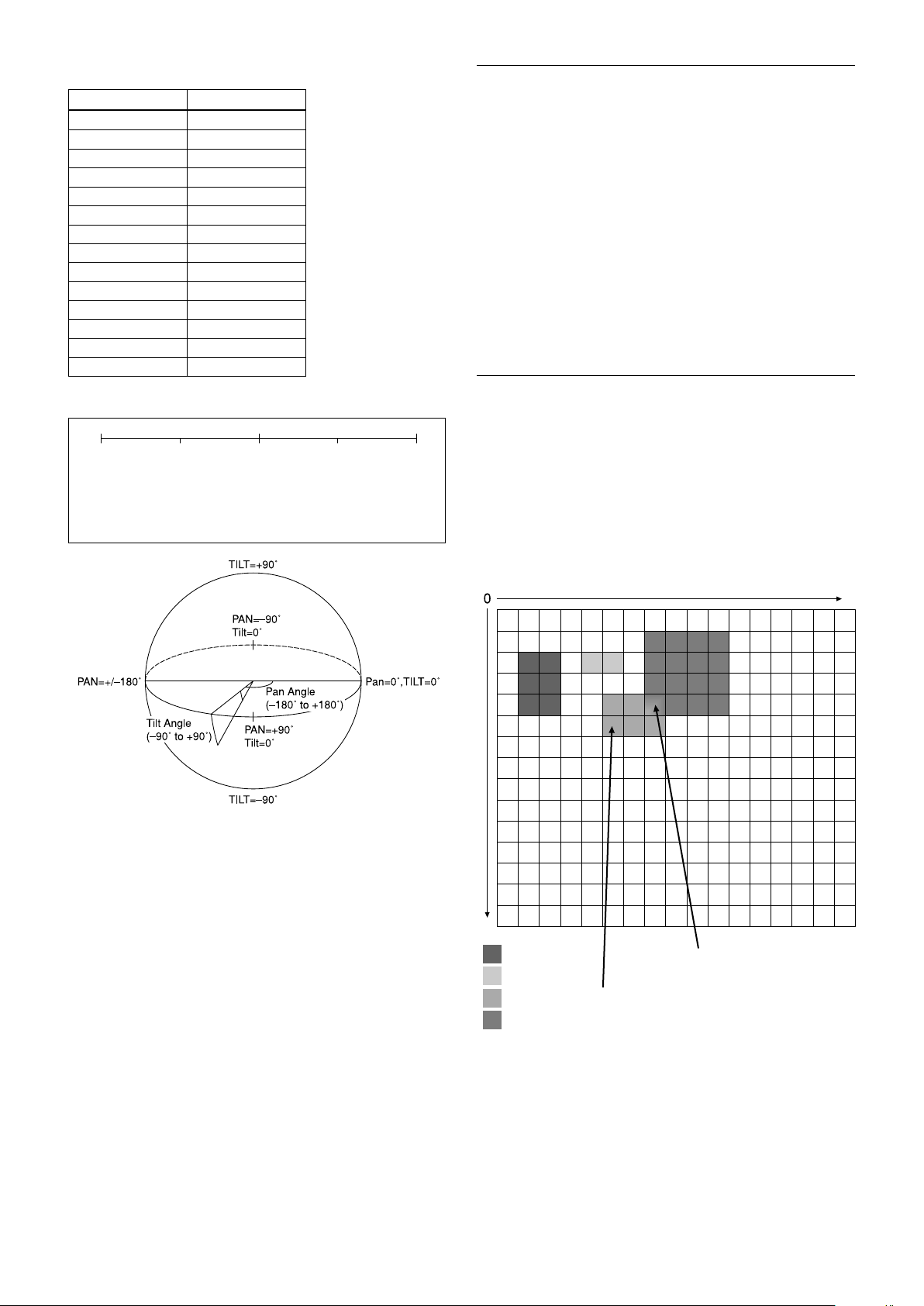
Spot Exposure Mode
In Full Auto AE, the level for the entire screen is
computed and the optimum Auto Iris and Gain levels
are determined. In Spot AE, a particular section of the
subject can be designated, and then that portion of the
image can be weighted and a value computed so that
Iris and Gain can be optimized to obtain an image.
For example, in an image with a lot of movement and
with varying levels of brightness, portions without
much change can be designated as such a “spot,” and
changes to the screen can be minimized in that area.
As shown in the diagram below, a range of 15 blocks
vertically and 17 blocks horizontally can be designated.
In the case where the center is designated (shown in
black), the level is computed along with a weighted
value for the surrounding block (shaded), including the
specified portions; and then the Gain and Iris are set.
The value of the designated portions and the
surrounding areas should be calculated as 100%, the
rest should be set to 20%. The range of the Spot AE
frame is fixed to 5 blocks vertically and 4 blocks
horizontally.
AE – Iris Priority
The iris can be set freely by the user to 14 steps
between F1.6 and Close.
The gain and shutter speed are set automatically,
according to the brightness of the subject.
Data
11 F1.6 0A F5.6
10 F2 09 F6.8
0F F2.4 08 F8
0E F2.8 07 F9.6
0D F3.4 06 F11
0C F4 05 F14
0B F4.8 00 CLOSE
Setting value
Data
Setting value
Note
Wide-D/HLC/Backlight Compensation/Spot Exposure Mode do
not work at the same time.
9

Basic Functions
Exposure Compensation
Exposure compensation is a function which offsets the
internal reference brightness level used in the AE
mode, by steps of 1.5 dB.
Data Step
0E +7 +10.5 dB
0D +6 +9 dB
0C +5 +7.5 dB
0B +4 +6 dB
0A +3 +4.5 dB
09 +2 +3 dB
08 +1 +1.5 dB
07 0 0 dB
06 −1 −1.5 dB
05 −2 −3 dB
04 −3 −4.5 dB
03 −4 −6 dB
02 −5 −7.5 dB
01 −6 −9 dB
00 −7 −10.5 dB
Setting value
Slow AE (Auto Exposure)
The slow AE Response function allows you to reduce
the exposure response speed. Usually the camera is set
up so that the optimum exposure can be obtained
automatically within about 1 second. However, using
the slow AE response function allows you to lengthen
the auto exposure response speed from the initial setup
speed (01h) to approx. 10 minutes (30h) (at normal
shutter speed).
For example, with the normal setting (about 1 second),
if the headlights of a car are caught by the camera, the
camera automatically adjusts the exposure so that it can
shoot a high-intensity subject (in this case, the
headlights). As a result, images around the headlights,
that is, the rest of the subject, except the headlights,
becomes relatively dark, and poorly distinguished.
However, using the slow AE function means the AE
response speed will be slower, and response time will
be longer. As a result, even if the camera catches a highintensity subject (e.g., the headlights) for a moment,
you can still easily distinguish the portions of the image
surrounding the headlights.
Aperture Control
Aperture control is a function which adjusts the edge
enhancement of objects in the picture. There are 16
levels of adjustment, starting from “no enhancement.”
When shooting text, this control may help by making
them sharper.
Backlight Compensation
When the background of the subject is too bright, or
when the subject is too dark due to shooting in the AE
mode, back light compensation will make the subject
appear clearer.
Note
Wide-D/HLC/Backlight Compensation/Spot Exposure Mode do
not work at the same time.
Wide Dynamic Range Mode (Wide-D)
The Wide Dynamic Range mode is a function for
dividing an image into several blocks and correcting
blocked-up shadows and blown-out highlights in
accordance with the intensity difference. It enables you
to obtain images in which portions ranging from dark
to light can be recognized, even when capturing a
subject with a large intensity difference that is backlit
or includes extremely light portions.
Images with wide dynamic range are produced by
combining long-exposure signals (normal shutter) with
the signals of the high-intensity portions obtained with
a short exposure (high-speed shutter).
• About Wide-D Set Parameter
(Command: 8x 01 04 2D 00 0q 0r 0s 00 00 00 00 FF)
q: Display brightness
(0: Dark to 6: Bright)
The brightness and the darkness can be
adjusted to seven levels. The normal brightness
is set to 3.
Initial setting: 3
r: Brightness compensation selection
(0: Darker, 1: Dark, 2: Standard, 3: Bright)
Set the area which you want to adjust the
brightness of the image with Wide-D effect.
Initial setting: 2
s: Compensation level
(0: Low, 1: Mid, 2: High)
The compensation of the brightness, which you
select from the parameter, can be set to three
levels.
Initial setting: 1
Notes
• When the Wide-D is On, false colors may appear in some parts of
the image. This phenomenon is unique to Wide-D, and is not an
indication of a camera malfunction.
• When Wide-D is switched, images may be disported.
• Wide-D/HLC/Backlight Compensation/Spot AE do not work at
the same time.
• After the Wide-D ON/OFF switchover, the Visca command will
not be accepted for up to 2 seconds and an error message may be
returned from the camera.
10

Basic Functions
Visibility Enhancer (VE)
Depending on the imaging scene, the Visibility
Enhancer function makes the darker part of a camera
image brighter, and automatically correct brightness
and contrast to show bright parts clearly.
Note
This function is also used in the Wide-D operation.
Defog mode
When the surrounding area of the subject is foggy and
low contrast, the defog mode will make the subject
appear clearer.
You can select this function from the four levels: OFF,
Low, Middle and High.
HLC
HLC (highlight correction) is a function to adjust AE
and AF, and to perform the masking of light area as
required when a high intensity spot light is detected.
It allows you to easily read the number of vehicles and
number plate in the indoor parking area or in the
outdoor during the night.
Note
Wide-D/HLC/Backlight Compensation/Spot Exposure Mode do
not work at the same time.
MinimumShutter
• In the normal setting, you can select the noise
reduction level from 6 levels: levels 1 to 5, plus off.
In this setting, the users cannot adjust the ratio of
2D/3D effect level.
• In the independent setting, you can individually select
the 2D NR and 3D NR from 6 levels respectively:
levels 1 to 5, plus off.
The NR effect is applied in levels based on the gain,
and this setting value determines the limit of the effect.
In bright conditions, changing the NR level will not
have an effect.
High sensitivity mode
This function increases the max gain to allow bright
output in darker environments.
However, with a strong gain (up to 10×), the captured
image will contain a lot of noise.
Note
When Wide-D is ON, the High sensitivity mode does not work.
Flicker Reduction
This function automatically reduces flicker such as that
caused by fluorescent light.
When the camera detects flicker, it automatically
changes the shutter speed and reduces flicker.
The shutter speed is automatically selected according to
conditions such as subject brightness and the Auto
Slow Shutter setting.
See the table below for the shutter speed to be selected.
When the subject becomes dark, the shutter speed
becomes slow, and then the gain is increased. This is a
function to put a limit on the shutter speed.
It prevents the camera shake when you shoot a moving
subject in a dark place.
Noise Reduction (NR)
The NR function removes noise (both random and
non-random) to provide clearer images.
The functions of both 2D NR (removal of 2dimentional noise) and 3D NR (removal of 3dimentional noise) are provided. When the 2D NR
level is increased, the details of image may be lost
because the smoothing of image with the peripheral
area is performed. Also, when the 3D NR level is
increased, adverse effects such as image blur and
blending in the successive images occur in the moving
portion. In this function, the mode to set the level of
effect by combining 2D/3D (normal setting) and the
mode to individually set the level of effect respectively
(independent setting) are available.
Video
mode
60 FPS 50 Hz Auto Slow Shutter OFF: 1/100
30 FPS 50 Hz Auto Slow Shutter OFF: 1/100, 1/50
50 FPS 60 Hz Auto Slow Shutter OFF: 1/120, 1/60
25 FPS 60 Hz Auto Slow Shutter OFF: 1/120, 1/60, 1/30
Flicker
Frequency
Shutter speed
Auto Slow Shutter ON: 1/100, 1/50, 1/25,
1/12.5
Auto Slow Shutter ON: 1/100, 1/50, 1/25,
1/12.5
Auto Slow Shutter ON: 1/120, 1/60, 1/30,
1/15
Auto Slow Shutter ON: 1/120, 1/60, 1/30,
1/15
If the camera does not detect flicker, it will run normal
AE operation.
Notes
• This function operates only during AE-Full Auto.
• Flicker Reduction does not work in AE-Shutter Priority/Iris
Priority/Manual/Spot Exposure Mode or Wide Dynamic Range
Mode.
• After the camera detects flicker and the shutter speed is changed,
Extended Normal Shutter and Minimum Shutter are inoperative.
11
Basic Functions
• The Flicker Reduction may not work if the subject is bright under
an environment where flicker occurs. If the shutter speed is 1/100
(flicker frequency 50 Hz) or 1/120 (flicker frequency 60Hz) and
the brightness exceeds the Iris variable area (F14), stop the Flicker
Reduction and run a normal AE operation.
Variable Gamma Mode
There are standard (00h) mode and straight gamma
(01h) mode.
Gamma Offset
You can set the brightness from –64 to +64 in each
mode of variable gamma mode.
Contrast Adjustment Function
You can adjust the contrast level in the range from
0 (00h) to 255 (FFh). The initial setting is 128 (80h).
The smaller the value is, the lower the contrast
becomes, and the larger the value is, the higher the
contrast becomes.
Note
This function is available when the variable gamma mode is set to
standard (00h) mode and when VE/Wide-D/HLC are set to OFF.
Temperature Reading Function
The conversion value (hex) of the temperature sensor
built into to the camera can be read by using a query
command. The conversion value has an error of ±3 °C,
and because the temperature sensor is inside the
camera, this value is not the ambient temperature. Use
it as a reference value.
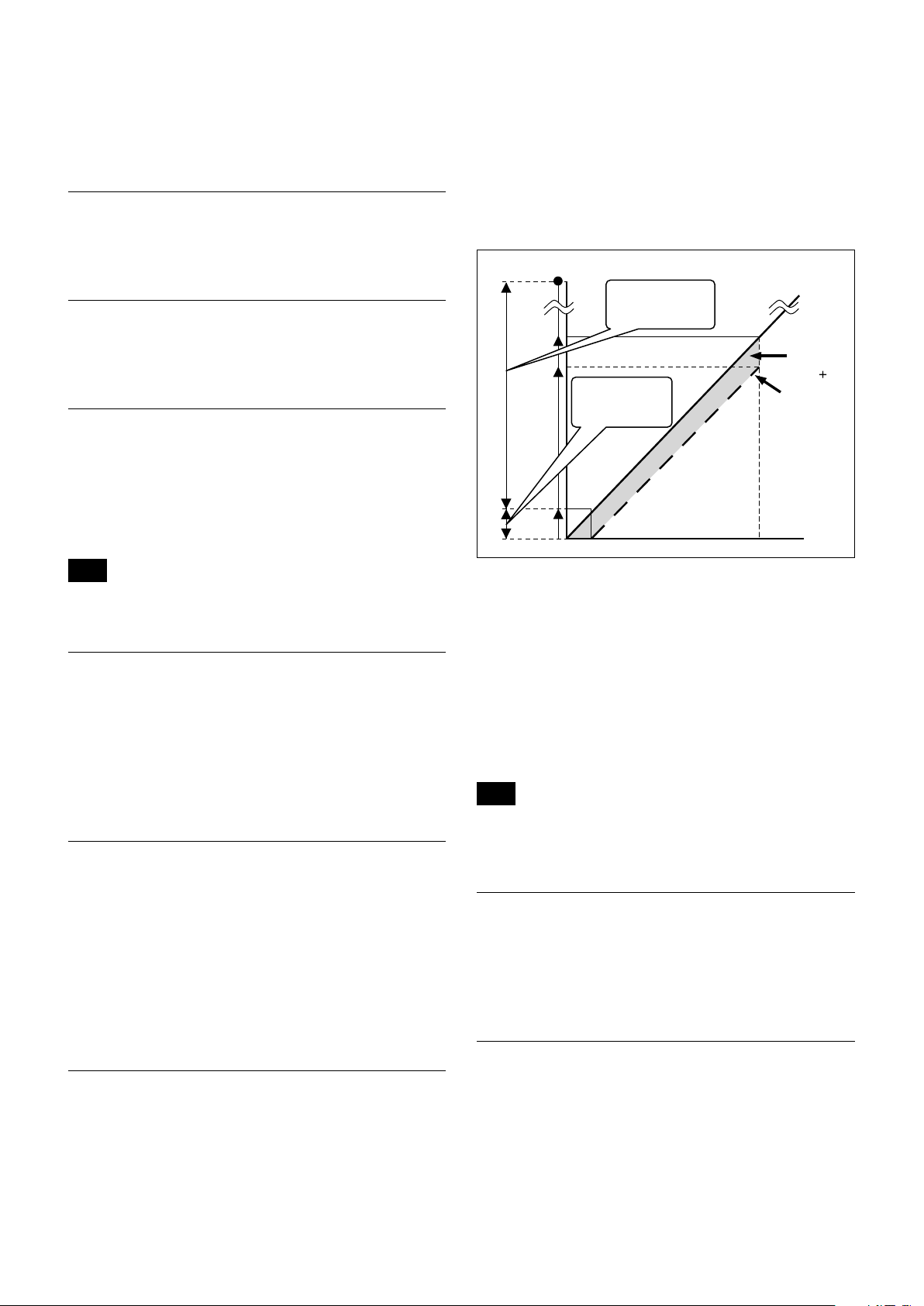
Image Stabilizer
zoom and digital zoom. As no digital zoom by the
Image Stabilizer is available on the wide side, you can
obtain a wider image with no resolution degradation.
Only the electronic zoom operates between Wide end
and 1.2×, and only the optical zoom operates between
1.2× and Tele end. The Image Stabilizer does not work
between Wide end and 1.2×, and only works after 1.2×.
The “StableZoom” function can be switched On/Off in
the register settings.
Up to
360x
Image Stabilizer
approx.
36x
30x
1.2x
Wide Optical zoom position Tele
ON
Image Stabilizer
OFF
“StableZoom”
Digital
zoom
+
Optical
zoom
Hold Function of Image Stabilizer
With the Image Stabilizer function, suddenly stopping
high-speed movement (pan, tilt, etc.) of the camera
produces a blur sensor counteraction that may cause
image movement. In such a case, you can use a
command setting (hold) to maintain the correction of
the Image Stabilizer function. In this case the image
stabilizer is off, but there is no change in the angle of
view.
Note
The hand shake correction function may not work correctly under
the condition that high-frequency vibra tion component exits. In
such a case, set the image stabilizer function to Off.
Switching On the Image Stabilizer function reduces
image blurring caused by, for example, vibration, which
allows you to obtain images without much blurring. A
correction effect is possible for a vibration frequency of
around 10 Hz. The Image Stabilizer function employs
the digital zoom system, so the angle of view and
resolution are changed, but the sensitivity is
maintained.
“StableZoom”
“StableZoom” is a function for performing correction
using the Image Stabilizer function in accordance with
the zoom ratio, and smoothly zooming up to
approximately 36× using a combination of the optical
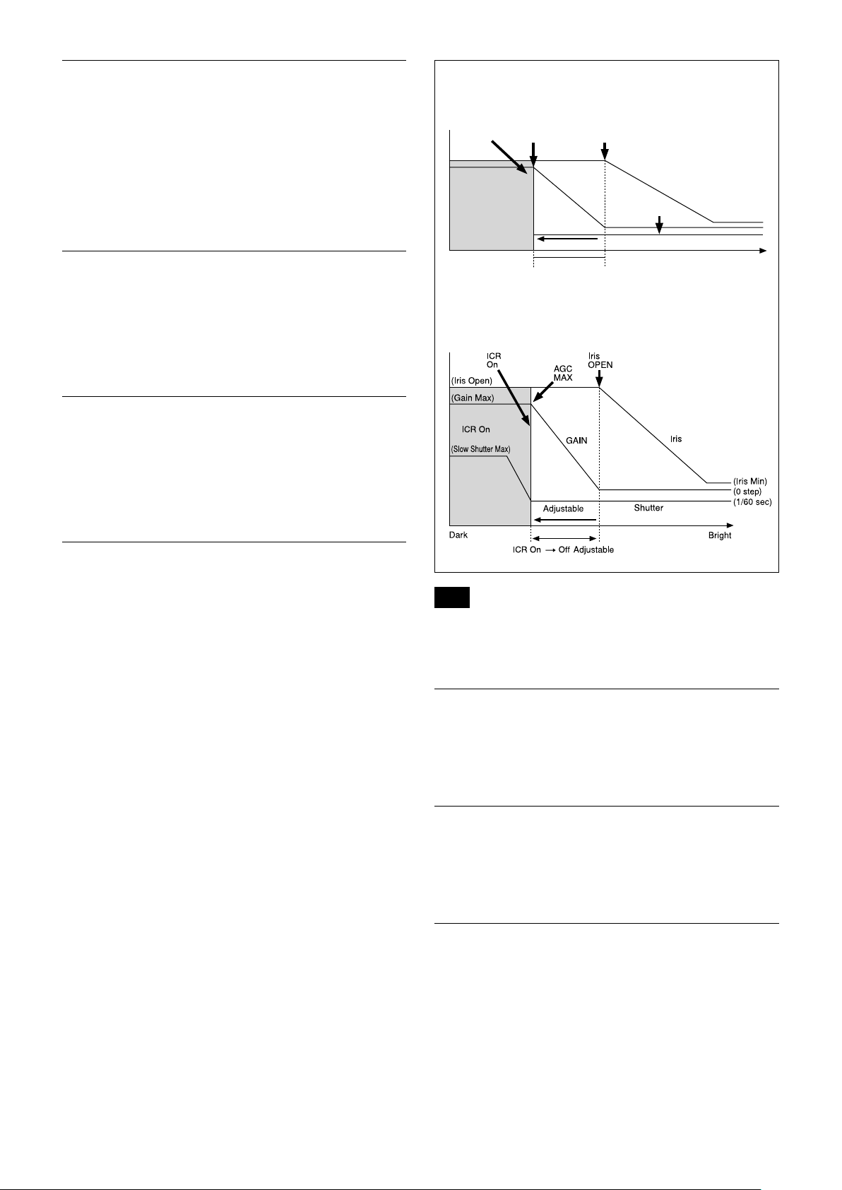
Auto Slow Shutter On/Off
When set to “On,” the slow shutter functions
automatically when the light darkens. This setting is
available only when the AE mode is set to “Full Auto.”
The initial setting is “Auto Slow Shutter Off.”
Low-Illumination Chroma Suppress Mode
You can configure a chroma suppress mode for lowillumination conditions. This can be useful when color
noise is particularly noticeable in such conditions.
Four levels (disabled and three levels) are available for
the low-illumination chroma suppress mode.
12
Basic Functions
ICR
Shutter
Dark Bright
AGC
MAX
Iris
OPEN
Shutter 1/60 sec
ICR Off On
GAIN
ICR On
Iris
ICR (IR Cut-Removable) Mode
An infrared (IR) Cut-Filter can be disengaged from the
image path for increased sensitivity in low light
environments. The ICR will automatically engage
depending on the ambient light, allowing the camera to
be effective in day/night environments.
When the auto ICR mode is set to On, the image
becomes black and white.
Custom Color Gain
You can configure the color gain.
The initial setting is 4h and the setting can be set to 15
levels from 0h to Eh.
The higher the setting value, the higher the color
saturation. The lower the setting value, the lower the
color saturation.
Custom Color Phase
You can configure the color phase.
The initial setting is 7h and the setting can be set to 15
levels from 0h to Eh.
The higher the setting value, the color phase shifts to
the + side. The lower the setting value, the color phase
shifts to the − side.
When Auto Slow Shutter is Off (initial setting)
When Auto Slow Shutter is On
Auto ICR Mode
Auto ICR Mode automatically switches the settings
needed for attaching or removing the IR Cut Filter.
With a set level of darkness, the IR Cut Filter is
automatically disabled (ICR On), and the infrared
sensitivity is increased. With a set level of brightness,
the IR Cut Filter is automatically enabled (ICR Off).
Also, on systems equipped with an IR light, the internal
data of the camera is used to make the proper decisions
to avoid malfunctions.
Auto ICR Mode operates with the AE Full Auto setting.
Note
Depending on the information such as brightness, etc., in the On/
Off settings condition, a malfunction may occur when the subjects
largely consisting of blue and green colors are taken.
Camera ID
The ID can be set up to 65,536 (0000h to FFFFh). As
this will be memorized in the nonvolatile memory
inside, data will be saved.
Picture Effect
It consists of the following functions.
• Black & White: Monochrome Image
Others
E-FLIP
This function reverses the video output from the
camera vertically and horizontally.
13

Basic Functions
LR Reverse
This function reverses the video output from the
camera horizontally.
Freeze
This function captures an image in the field memory of
the camera so that this image can be output
continuously.
Note
Because communication inside the camera is based on V cycle, the
captured image is always the one 3V to 4Vs after the sending of a
Command. Thus, you can not specify a time period after sending
EVEN, ODD or a Command.
Memory (Position preset)
Using the position preset function, 16 sets of camera
shooting conditions can be stored and recalled.
This function allows you to achieve the desired status
instantly, even without adjusting the following items
each time.
• Zoom Position
• Digital Zoom On/Off
• Focus Auto/Manual
• Focus Position
• AE Mode
• Shutter control parameters
• Iris control parameters
• Gain control parameters
• Exposure Compensation On/Off
• Exposure Level
• Backlight Compensation On/Off
• Auto Slow Shutter On/Off
• White Balance
• R/B Gain
• Aperture Control
• ICR On/Off
• Defog
• Wide-D On/Off
• Wide-D Parameter
• VE On /Off
• VE Parameter
• Minimum Shutter Mode
• Minimum Shutter Limit
Custom Preset
As with the position preset function, the camera
shooting conditions can be stored and recalled. The
settings are recalled when the power is turned on.
For setting items, see the “Initial Settings, Custom Preset
and Backup” section on page 24.
User Memory Area
This is the memory area with 16-byte capacity which
users can overwrite freely.
This can be used as a Serial No. for individual
recognition.
Note
Rewriting of memory is not unlimited. Be careful to avoid using the
memory area for such as unnecessary tasks as rewriting the
contents of the memory for every operation.
Register Setting
The camera’s initial settings can be changed by the
register setting command.
Register Setting Command:
8x 01 04 24 mm 0p 0q FF
mm: Register No. (=00 to 7F)
pq: Register Value (=00 to FF)
Register Inquiry Command:
8x 09 04 24 mm FF
mm: Register No.
y0 50 0p 0p FF
pp: Register Value
(returned from the camera.)
The register setting items and No. are as follows.
For details, see “Register Setting” on page 54.
Baud Rate: 00
Communication speed can be changed.
Monitoring Mode: 72
The output mode can be set.
LVDS Mode: 74
LVDS output mode can be set.
Zoom Limit: 50 (Wide end), 51 (Tele end)
The Wide and Tele zoom limits can be set.
D-Zoom Max: 52
The maximum digital zoom limit can be set (initial
settinig is 12×).
“StableZoom”: 53
ON/OFF can be set. (initial setting is OFF.)
For details, see “StableZoom” on page 12.
FocusTrace: 54
When you want to prioritize zoom speed, set
FocusTrace to Off to minimize the transition time
between Wide and Tele zoom (although the image
may be blurred because focus is not tracked).
FocusOffset: 55
Placing a dome cover in front of the camera may
cause the focal distance of the camera to change.
Especially at the Tele end, this effect exceeds the AF
range, so focus cannot track, although it responds
to changes in this value.
For details, see “Register Setting” on page 54.
AE parameter change during VE On, Defog On: 58
ON/OFF can be set. (initial setting is ON.)
14
Basic Functions
Auto slow shutter limit: 59
The auto slow shutter limit can be set. (initial
setting is 04.)
For details, refer to “Register Setting” (page 54).
Extended normal shutter: 5A
The lower limit of slow shutter when the Auto Slow
Shutter mode is set to OFF can be set. (initial
setting is OFF.)
Defog Limit: 5B, 5C, 5D
The maximum value of Defog mode in the low,
mid and high levels can be set respectively.
Extended mode: 5F
ON/OFF can be set. (initial setting is OFF.)
For details, see “Extended mode” on page 54.
Note
After changing the register setting, turn off the camera, then turn it
on again.
Privacy Zone Masking Settings
For details, see “Privacy zone masking function” on
page 16
.
Title Display
• You can set a title of up to 11 lines. One line can
contain up to 20 characters.
• You can set display on/off, the horizontal position of
the first character, blinking state and color for each
line.
• The camera gives priority to a title display when the
camera status is displayed on the relevant line. On the
lines where a title is not set, the camera status is
displayed.
Line Number 00h to 0Ah
H-position 00h to 1Fh
00h WHITE
01h YELLOW
02h VIOLET
Color
Blink
03h RED
04h CYAN
05h GREEN
06h BLUE
00h Off
01h On
Motion detection
For details, see “Motion detection (MD) function” on
page 18
.
00 01 02 03 04 05 06 07
A B C D E F G H
08 09 0A 0B 0C 0D 0E 0F
I J K L M N O P
10 11 12 13 14 15 16 17
Q R S T U V W X
18 19 1A 1B 1C 1D 1E 1F
Y Z & ? ! 1 2
20 21 22 23 24 25 26 27
3 4 5 6 7 8 9 0
28 29 2A 2B 2C 2D 2E 2F
À È Ì Ò Ù Á É Í
30 31 32 33 34 35 36 37
Ó Ú Â Ê Ô Æ Ã
38 39 3A 3B 3C 3D 3E 3F
Õ Ñ Ç ß Ä Ï Ö Ü
40 41 42 43 44 45 46 47
Å $ ¥ £ ¿ ¡
48 49 4A 4B 4C 4D 4E 4F
ø ” : ’ . , / -
15

Basic Functions
Privacy Zone Masking Function
Privacy Zone masking protects private objects and
areas such as house windows, entrances, and exits
which are within the camera’s range of vision but not
subject to surveillance.
Privacy zone masking can be masked on the monitor to
protect privacy.
Features
• Mask can be set on up to 24 places according to Pan/
Tilt positions.
• Mask can be displayed on 8 places per screen
simultaneously.
• Individual on/off zone masking settings.
• Two colors can be individually set for each of
24 privacy zones.
• Interlocking control with zooming.
• Interlocking control with Pan/Tilt.
• Non-interlocking control with Pan/Tilt.
Set Display
Command: 8x 01 04 77 pp pp pp pp FF
Parameter:
pp pp pp pp Each 24 Privacy Zones corresponds to the BIT.
See “pp pp pp pp: Mask bit” in “Parameters” on
page 17.
Comments: Each of 24 Privacy zones can be switched
on and off individually by a single VISCA
Command. If you want to display a Privacy zone,
you must set its bit to 1. If you do not want to
display a Privacy zone, you must set its bit to 0.
Set Mask Color
Command: 8x 01 04 78 pp pp pp pp qq rr FF
Parameter:
pp pp pp pp Each 24 Privacy Zones correspond to the BIT.
See “pp pp pp pp: Mask bit” in “Parameters” on
page 17.
qq Set the color code
rr Set the color code. See “qq, rr: Color code” in
“Parameters” on page 17.
Details of Setting Commands
Set Mask
Command: 8x 01 04 76 mm nn 0r 0r 0s 0s FF
Parameters:
mm Setting Mask
See “mm: Mask setting list” in “Parameters” on page 17.
nn Selects new setting or resetting for the zone. See “nn:
Setting” in “Parameters” on page 17.
rr Sets the half value “w” of the Mask Width.
ss Sets the half value “h” of the Mask Height.
See “pp: x, qq: y, rr: w, ss: h” in “Parameters” on page 17.
Comments: To set the mask, first display the object at
the center of the screen. When “nn” is set to 1, the
current Pan/Tilt/Zoom Position is recorded in
internal memory.
When “nn” is set to 0, the Pan/Tilt/Zoom Position
in memory is not changed.
Notes
• The tilt angle at which you can set the mask is between –70 to
+70 degrees.
• It is recommended that you set the size to at least twice the size
of the object (height and width).
Comments: Two different color masks can be chosen.
Two colors can be individually set for each of
24 privacy zones.
If the bit of parameter (pp pp pp pp) is set to “0”,
mask color will be “qq” color (Color code). If the
bit of parameter (pp pp pp pp) is set to “1”, the
mask color will be “rr” color (Color code).
Example: 8x 01 04 78 00 00 00 03 00 07 FF
The mask color of Mask_A and Mask_B is White
(color code 07h), and the mask color of the other
Mask (C to X) is Black (color code 00h).
Set Pan Tilt Angle
Command: 8x 01 04 79 0p 0p 0p 0q 0q 0q FF
Parameter:
ppp Pan Angle
qqq Tilt Angle
See “Setting pan/tilt angle” in “Parameters” on
page 18.
Comments: Pan/Tilt angle settings are hexadecimal
data.
The resolution of Pan/Tilt angle is 0.088 degrees.
Notes
• When you set the pan/tilt angle, locate the pan/tilt position at
the center point of the FCB camera’s position.
• If you set the pan/tilt angle or zoom the camera, a bigger mask
will be displayed for about one second.
16
Basic Functions
160
90
0h(x,y)
w
B0h
D3h
2Dh
50h
Set PTZ Mask
Command: 8x 01 04 7B mm 0p 0p 0p 0q 0q 0q 0r 0r
0r 0r FF
Parameter:
mm Setting Mask
See “mm: Mask setting list” in “Parameters” on page 17.
ppp Pan Angle (000 to FFF)
See “Setting pan/tilt angle” in “Parameters” on page 17.
qqq Tilt Angle (000 to FFF)
See “Setting pan/tilt angle” in “Parameters” on page 17.
rrrr Zoom Position (000 to 4000)
See “Zoom Ratio and Zoom Position (for reference)” on
page 52.
Comments: Mask can be set at the desired position
by setting the pan tilt angle and zoom position
using this command.
The set value can be input by hexadecimal
number.
Note
Privacy mask zone follows the change of angle of view according
to zoom. However, the follow might be delayed for a moment if
there is any big change, such as when using D-Zoom or E-FLIP.
Parameters
mm: Mask setting list
Mask Name mm (Hex) Mask Name mm (Hex)
Mask_A 00h Mask_M 0Ch
Mask_B 01h Mask_N 0Dh
Mask_C 02h Mask_O 0Eh
Mask_D 03h Mask_P 0Fh
Mask_E 04h Mask_Q 10h
Mask_F 05h Mask_R 11h
Mask_G 06h Mask_S 12h
Mask_H 07h Mask_T 13h
Mask_I 08h Mask_U 14h
Mask_J 09h Mask_V 15h
Mask_K 0Ah Mask_W 16h
Mask_L 0Bh Mask_X 17h
nn:Setting
nn Setting
00h Resetting the zone size (the value of w, h)
for the existing mask.
01h Setting newly the zone size (the value of w, h).
pp: x, qq: y, rr: w, ss: h
Non Interlock Mask
Command: 8x 01 04 6F mm 0p 0p 0q 0q 0r 0r 0s 0s
FF
Parameters:
mm Setting Mask
See “mm: Mask setting list” in “Parameters” on page 17.
pp Sets the center position “x” of the Mask on screen.
qq Sets the center position “y” of the Mask on screen.
rr Sets the half value “w” of the Mask Width.
ss Sets the half value “h” of the Mask Height.
See “pp: x, qq: y, rr: w, ss: h” in “Parameters” on page 17.
Commands: Mask does not interlock with pan/tilt.
The limitations of parameters are as follows.
(hexadecimal representation)
x: ±50h w: ±50h
y: ±2Dh h: ±2Dh
Note
When the Set Mask command and the Non Interlock Mask
command are set to the same mask, the command set later
becomes effective.
mask
Effective display area
Note
The priority order of the mask display is in the sequence from
A (highest) to X (lowest). When you set the parameters of masks
non-sequentially, it is recommended that you set the mask whose
priority order is higher, first.
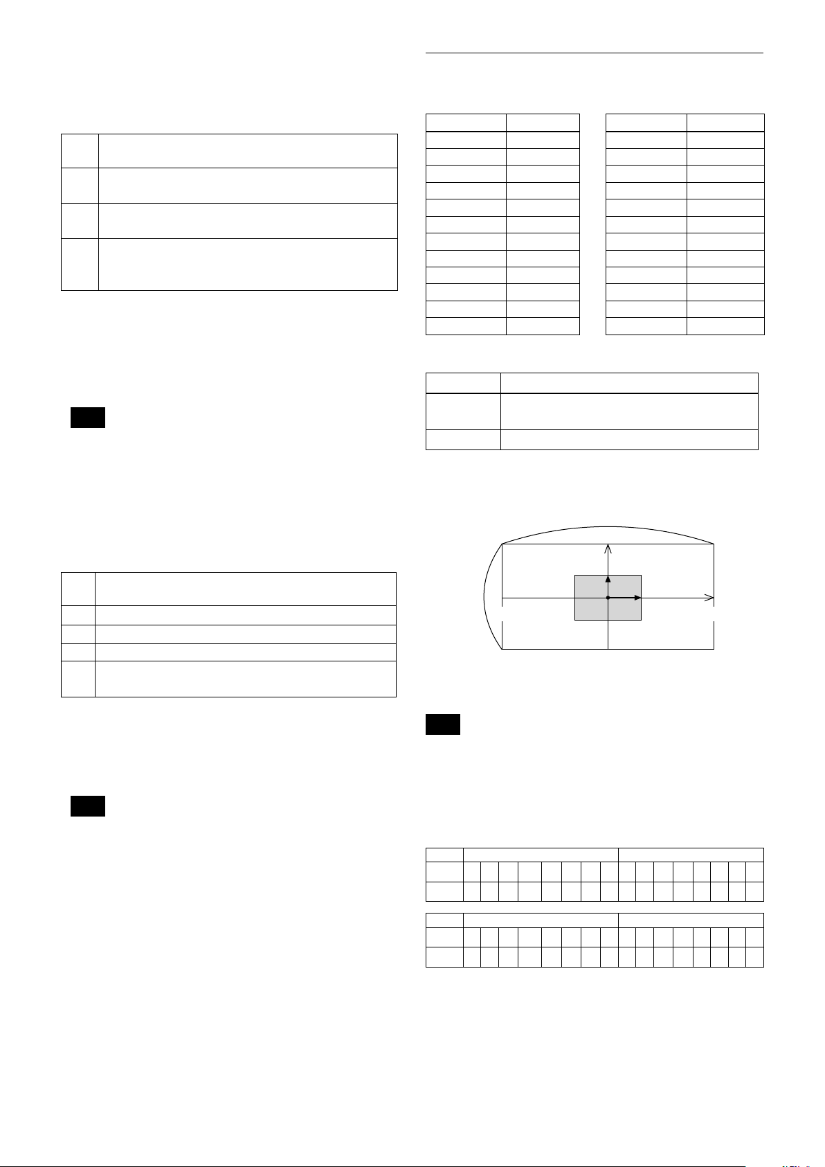
pp pp pp pp: Mask bit
pp pp
bit 7 6 5 4 3 2 1 0 7 6 5 4 3 2 1 0
Mask - - X W V U T S - - R Q P O N M
pp pp
bit 7 6 5 4 3 2 1 0 7 6 5 4 3 2 1 0
Mask - - L K J I H G - - F E D C B A
The “-” must be “0”.
17
Basic Functions
0 90-180 -90 180
400h800h C00h 800h
17
15
qq, rr: Color code
Mask (color) Code (qq, rr)
Black 00 h
Gray1 01 h
Gray2 02 h
Gray3 03 h
Gray4 04 h
Gray5 05 h
Gray6 06 h
White 07 h
Red 08 h
Green 09 h
Blue 0A h
Cyan 0B h
Yellow 0C h
Magenta 0D h
Setting pan/tilt angle
Angle/Parameter of Angle (ppp, qqq)
Set the angle resolution to 360 (degree)/4096 (1000h).
Features
• You can set a frame for the detection range of
17 (horizontally) × 15 (vertically) blocks.
• You can set up to four frames.
• When the motion is detected in the set frame, the
Alarm Replay VISCA Command is sent.
• The threshold level for detection can be set (common
to four frames).
• The interval of alarm detection can be set up to
255 seconds in units of one second.
• You can set ON/OFF for each frame.
• The frame number is also sent with Alarm Replay to
report in which frame the motion has been detected.
Frames
Setting frames
You can set the frame by assigning the starting point
and terminating point vertically and horizontally.
You can set up to four frames.
When motion is detected within the range where
frames overlap
The alarms are sent for both frames.
Motion Detection (MD) Function
This function instructs the camera to detect movement
within the monitoring area and then send an alarm
signal automatically.
The Detect signal goes out through the VISCA
Command.
18
Frame 1
Frame 2
Frame 3
Frame 4
Within this overlapped
range, alarms are sent for
both frame 3 and frame 4.
At this position, the
alarm for frame 3 is
sent.
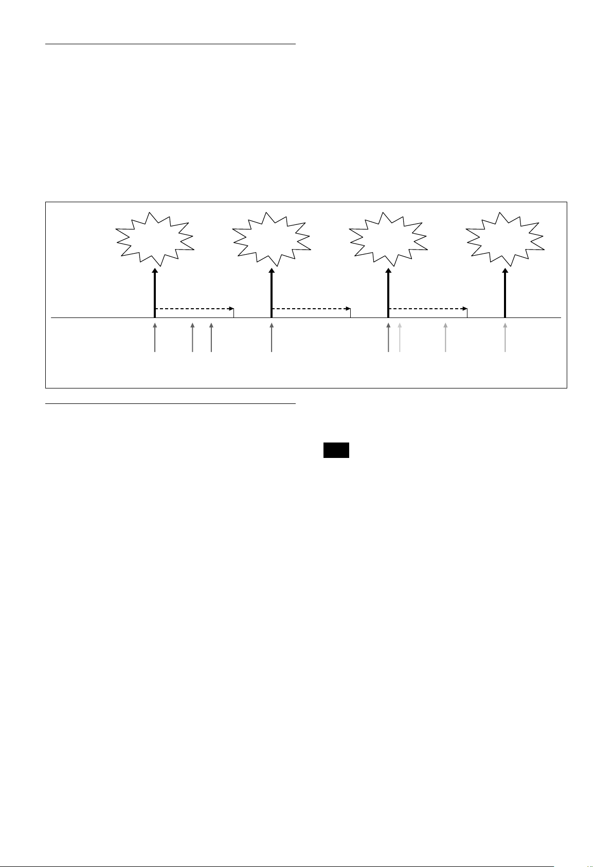
Sending Alarms
• When motion is detected, the Alarm Replay
command is issued via the serial command (VISCA)
communication line.
• When multiple motions are detected or motion is
detected in another frame within the set interval
following the original time the alarm was issued,
another alarm command is not issued.
• When motion is detected after the interval time
elapsed, the alarm is issued again.
Alarm issue Alarm issue Alarm issue Alarm issue
Basic Functions
Alarm interval
Motion is
detected in
frame 1.
Interval
Motion is
detected in
frame 1.
Motion is
detected in
frame 1.
Motion is
detected in
frame 1.
Setting Commands
• MD On/Off
The Display mode is selected by the Function Set
command and frames are set by the Frame Set
command. By sending an MD On command, the
frame is displayed when motion is detected in the set
frame. The Alarm Reply command is sent via the
serial command (VISCA) communication line.
8x 01 04 1B 02 FF --- On
8x 01 04 1B 03 FF --- Off
• Function Set
Select the detected frame, and set the Threshold Level
and the Interval Time.
8x 01 04 1C 0m 0n 0p 0q 0r 0s FF
m: Display Mode on/off (bit0)
n: Detection Frame set on/off (bit0:Frame0, bit1:
Frame1, bit2:Frame2, bit3:Frame3)
- (0 to F)
pq: Threshold - (00 to FF)
rs: Interval time set - (00 to FF)
(When pq and rs are 0, the command is received, but
the setting is disabled.)
Interval Interval
Motion is
detected in
frame 1.
Motion is
detected in
frame 2.
Motion is
detected in
frame 3.
Motion is
detected in
frame 3.
• Frame Set
You can set up to four frames by assigning the starting
and terminating points.
Note
Set a terminating point higher vertically and
horizontally than the starting point. If you set the
wrong value, an error occurs.
8x 01 04 1D 0m 0p 0q rr 0s FF
m: Select Detection Frame (0: Frame0, 1: Frame1,
2: Frame2, 3: Frame3) - (0, 1, 2, 3)
p: Frame set Start Horizontal Position - (00 to 10)
q: Frame set Start Vertical Position - (00 to 0E)
r: Frame set End Horizontal Position - (01 to 11)
s: Frame set End Vertical Position - (01 to 0F)
• Alarm Reply
When motion is detected in the set frame, the camera
issues this command. This command includes the
information on the number of the detected frame.
y0 07 04 1B 0p FF
p: Frame Number (bit0: Frame0, bit1: Frame1,
bit2: Frame2, bit3: Frame3)
19

Basic Functions
Extended Commands
Extended commands support the following functions
(described previously).
Turn on this mode (for details, see “Extended Mode” in
“Register Setting” on page 54) to enable the following
functions.
• Exposure Compensation
The setting can be set in steps of approximately 0.2dB
(–128 (00h) to approximately +127 (FFh)).
For details, see page 10.
• Aperture Control
The setting can be set to 256 levels (00h to FFh).
For details, see page 10.
• Custom Color Gain
You can configure the color gain.
The initial setting is 80h and the setting can be set to
256 levels from 00h to FFh.
The higher the setting value, the higher the color
saturation. The lower the setting value, the lower the
color saturation.
You can set the color saturation more widely and
finely than the normal color gain variable.
For details, see page 13.
• Custom Color Phase
You can configure the color phase.
The initial setting is 80h and the setting can be set to
256 levels from 00h to FFh.
The higher the setting value, the color phase shifts to
the + side. The lower the setting value, the color phase
shifts to the − side.
You can set the color phase more finely than the
normal color phase variable.
For details, see page 13.
• Auto ICR Mode
The setting of ICR ON→OFF threshold can be set
when Auto ICR is on.
The setting range is 0 step (00h) to 255 step (FFh).
The setting of ICR OFF→ON threshold (On Level)
can be set when Auto ICR is on.
The setting range is 0 step (00h) to 28 step (1Ch).
For details, see page 13.
Note
When the extended mode is Off, CMD_NOT_EXEC
will be returned if you send the extended commands
to the camera.
When the extended mode is On, CMD_NOT_EXEC
will be returned if you send the normal commands to
the camera.
User’s Updating
Overview
The details on the firmware version upgrade are
described.
To perform the firmware version upgrade, the
following three steps are required.
1) Shifting to the maintenance mode using the Visca
command
2) Binary transmission (X model protocol) of the
firmware in the maintenance mode
3) Finalizing setting using the Visca command
Each step is described as follows.
1) Shifting to the maintenance mode using the Visca
command
After entering the standby mode using the Visca
command, the unit shifts to the maintenance mode.
Note that if the power is turned off during the
writing, the program will be broken and cannot be
restored.
2) Binary transmission (X model protocol) of the
firmware in the maintenance mode
Serial Port Setting during maintenance mode
Communication Speed 115200 bps
Data bit 8 bit
Parity None
Stop bit 1 bit
Flow control None
In the maintenance mode, the terminal software
capable of sending the character command is used.
The terminal software that is provided with the
XMODEM binary transfer protocol is used.
When you transfer the camera firmware (uug.bin
file) using this function, the transferred file is
written in FlashROM. The writing takes
approximately 6 minutes.
Note that if the power is turned OFF during
writing, the program may be broken and may not
be restorable.
After the writing is completed, the unit restarts
automatically, and then the camera firmware is
started.
3) Finalizing setting using the Visca command
The finalizing setting is performed using the Visca
command.
You cannot read the correct camera firmware
version without performing this setting. Be sure to
perform this setting.
20
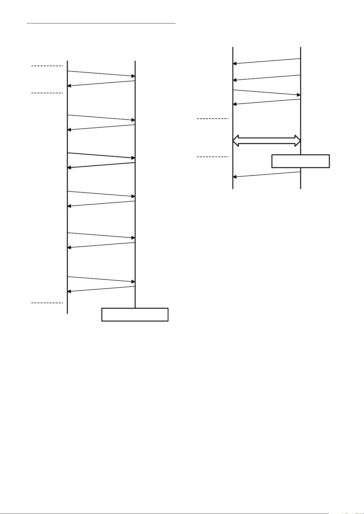
Basic Functions
HOST FCB
CAM_Power off
8x 01 04 00 03 FF
ACK, COMP
8x 01 04 00 0C FF
ACK, COMP
8x 01 04 00 0D FF
ACK, COMP
8x 01 04 00 13 FF
ACK, COMP
8x 01 04 00 04 FF
ACK, COMP
8x 01 04 00 20 FF
ACK, COMP
Enter
Standby
Mode
Enter
Maintenance
Mode
* Do not turn OFF the power while updating because
there is a possibility that the camera will break.
REBOOT AUTOMATICALLY
Sending firmware
Sending Firmware Binary
with X modem protocol
Firmware Update
Ready Message
HOST FCB
CODE NAME+
VERSION + CR
“ready” + CR
“reprogram ( )” + CR
“receive”+ CR
‘reboot’+ CR
* Writing in FlashROM
* Do not turn OFF the power while updating because
there is a possibility that the camera will break.
Update Procedure
Enter Maintenance Mode
Maintenance Mode
21
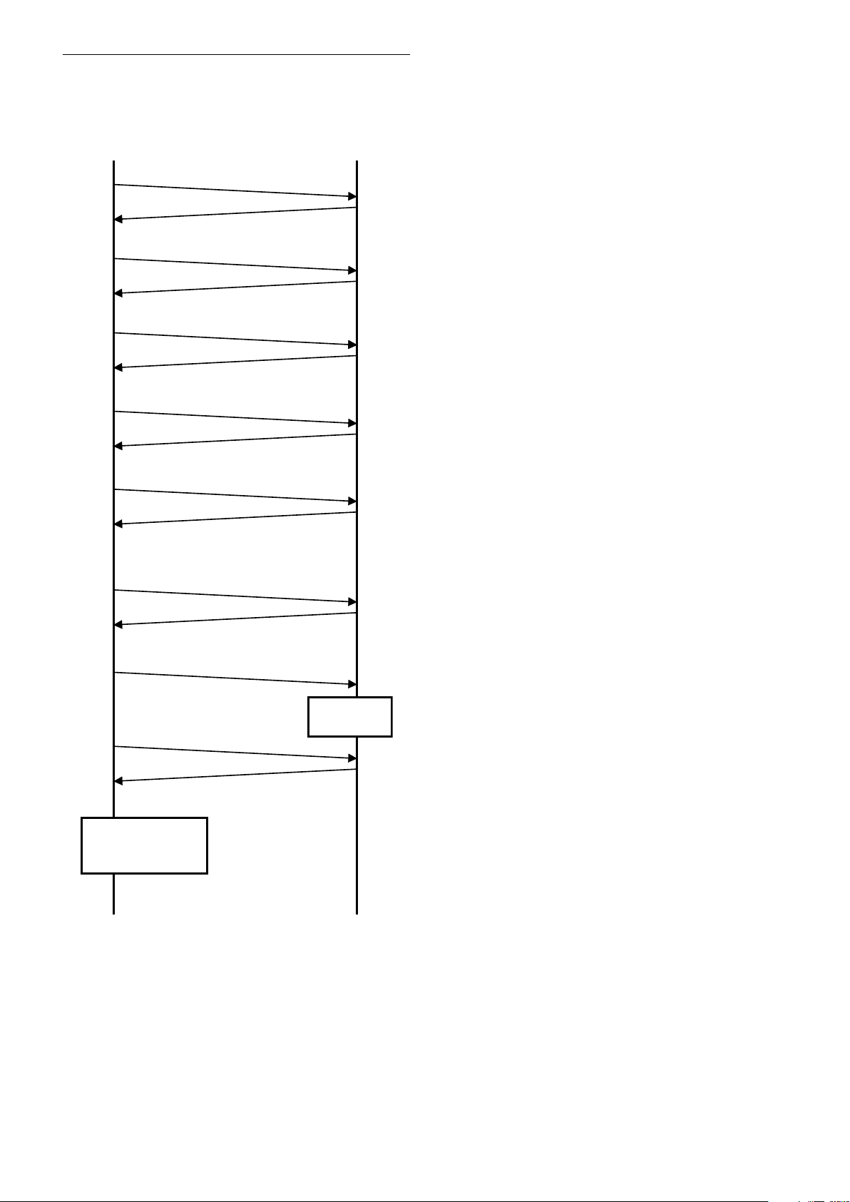
Finalizing procedure
HOST FCB
Reboots
automatically.
8x 01 7F 01 7F FF
ACK, COMP
8x 01 7F 7F 02 00 00 01 00 01 FF
ACK, COMP
8x 01 7F 7F 02 03 08 00 00 08 FF: EV7520A
ACK, COMP
8x 01 7F 7F 02 03 00 00 06 01 FF
ACK, COMP
8x 01 7F 7F 02 03 00 01 06 01 FF
ACK, COMP
8x 09 7F 7F 01 03 00 02 FF
8x 09 00 02 FF
9x 50 00 00 00 01 FF is received.*
1
8x 01 04 19 03 FF
9x 50 00 20 HH HH JJ JJ 02 FF is received.
Check that JJJJ is the
same as the updated
FW version. *
2
*1 When 9x 50 00 00 00 00 FF is received,
retransmit 8x 09 7F 7F 01 03 00 02 FF
until 9x 50 00 00 00 01 FF is received.
*2 If it is not the same, perform the
update procedure from the beginning.
After the maintenance mode, perform the following
finalizing procedure.
Basic Functions
22
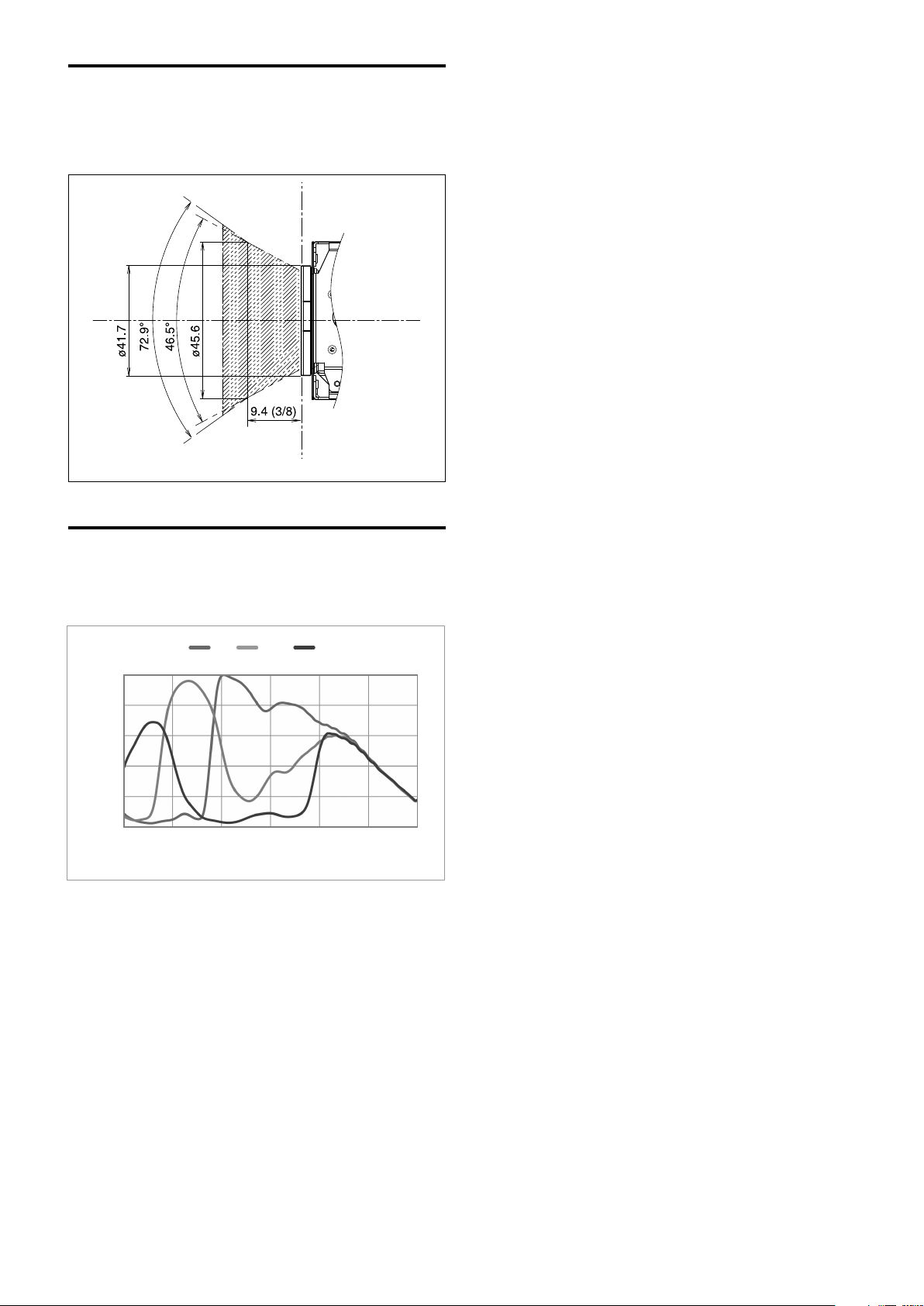
Eclipse
0.0
0.2
0.4
0.6
0.8
1.0
400 500 600 700 800 900 1000
Relative response [a.u.]
Wavelength [nm]
Red Green Blue
When designing the housing, refer to the dimensional
allowance as shown in the figure below.
unit: mm (inches)
Basic Functions
Spectral Sensitivity Characteristics
Use the graph as a reference value. (We can not
guarantee these values.)
This data is measured when the IR cut filter is removed
and the characteristics of the lens and optical source
characteristics are ignored.
23

Initial settings and backup of camera
“Initial settings” is the factory preset value.
“Custom Preset”, indicates data that can be stored with
preset function.
“Back up on standby” indicates that
is retained while on Standby and × is not retained.
and data that cannot be stored with × using the custom
Basic Functions
Mode/Position setting Initial Settings
Zoom Position Wide end
D-Zoom On/Off
D-Zoom Separate/Combine
D-Zoom Position
Focus Position
Focus Auto/Manual
Near Limit Setting
AF Sensitivity
AF Mode
AF Run Time 5 sec
AF Interval 5 sec
WB Mode
WB Data (Rgain, Bgain)
One Push WB Data
AE Mode Full Auto
AE Response
Auto Slow Shutter Mode
Shutter Position
Iris Position
Gain Position
Exposure Compensation On/Off
Exposure Compensation
Amount
BackLight On/Off
Spot AE On/Off
Spot AE Position Setting X=8 Y=7
Aperture Level
LR Reverse On/Off
Freeze On/Off
Picture Effect
ICR On/Off
Auto ICR On/Off
Auto ICR Threshold Level
Camera Memory Same as the initial value setting
Display On/Off
Mute On/Off
Auto ICR Alarm On/Off
Image Stabilizer On/Off/Hold
High Sensitivity mode On/Off
Gamma 0: standard
Defog On/Off
On
Combine
00h
—
Auto
D000h
Normal
Normal
Auto
—
—
01h
Off
—
—
—
Off
±0
Off
Off
Ah
Off
Off
Off
Off
Off
0Eh
Off
Off
Off
Off
Off
Off
Custom
Preset
Back up
at standby
24
 Loading...