

Sony FCB-ER8550, FCB-ER8530, FCB-CR8530, FCB-CR8550 Technical Manual

D-201-100-12(1)
Color Camera Module
Technical Manual
FCB-ER8550/8530
FCB-CR8550/8530
2018 Sony Corporation

Table of Contents
Precautions ....................................................................... 3
Locations of Controls .......................................................5
Basic Functions ................................................................. 6
Overview of Functions .....................................................................6
About the firmware update ........................................................ 18
Eclipse ................................................................................................. 23
Spectral Sensitivity Characteristics .......................................... 23
Initial Settings, Custom Preset and Backup .......................... 24
Mode Condition .............................................................................. 26
Command List .................................................................29
VISCA/RS-232C Commands ........................................................ 29
FCB Camera Commands .............................................................. 34
Specifications ................................................................. 68
Note on the License ........................................................72
2

Precautions
Software
Use of the demonstration software developed by Sony
Corporation or use of the software with customer
developed application software may damage hardware,
the application program or the camera. Sony
Corporation is not liable for any damages under these
conditions.
Operation
Start the camera control software on your computer
after you turn on the camera and the image is displayed.
Operation and storage locations
Do not shoot images that are extremely bright (e.g.,
light sources, the sun, etc.) for long periods of time. Do
not use or store the camera in the following extreme
conditions:
• Extremely hot or cold places (operating temperature
–5 ˚C to +60 ˚C (23 ˚F to 140 ˚F))
• Close to generators of powerful electromagnetic
radiation such as radio or TV transmitters
• Where it is subject to fluorescent light reflections
• Where it is subject to unstable (flickering, etc.)
lighting conditions
• Where it is subject to strong vibration
• Where it is subject to radiation from laser beams
Care of the unit
Remove dust or dirt on the surface of the lens with a
blower (commercially available).
• In case of abnormal operation, contact your
authorized Sony dealer or the store where you
purchased the product.
Handling precautions
• When handling this unit, be careful not to apply an
excessive load to all portions of the unit except for the
sheet-metal cover. Otherwise, it may result in a
failure.
• This unit is designed to be built in the housing.
Therefore, take measures to prevent the unit from
receiving the intense light such as sunlight directly
from the direction other than the front side.
Otherwise, it may cause the image quality
degradation.
Phenomena specific to CMOS image sensors
The following phenomena that may appear in images
are specific to CMOS image sensors. They do not
indicate malfunctions.
Rolling shutter
As CMOS image sensors use shutters that capture
images line-by-line, there is a slight time difference
between the top and bottom of an image. As a result,
images may appear skewed if the camera is moved.
White flecks
Although the CMOS image sensors are produced with
high-precision technologies, fine white flecks may be
generated on the screen in rare cases, caused by cosmic
rays, etc.
This is related to the principle of CMOS image sensors
and is not a malfunction.
Other
• Design and specifications are subject to change
without notice.
• Do not apply excessive voltage. (Use only the specified
voltage.) Otherwise, you may get an electric shock or
a fire may occur.
• The CMOS image sensor and IC included in this
camera may break if exposed to static electricity.
When directly handling this camera, wear an
antistatic strap, spread a conductive sheet or similar
item under your workbench, and take measures to
eliminate static electricity.
The white flecks especially tend to be seen in the
following cases:
• when operating at a high environmental temperature
• when you have raised the master gain (sensitivity)
• when operating in Slow-Shutter mode
Aliasing
When fine patterns, stripes, or lines are shot, they may
appear jagged or flicker.
3

Notes on incorporating a camera
When incorporating a camera on a device that turns
ON/OFF 3 times or more a day on average, please
confirm the temperature in the set using
communication command 'CAM_TempInq' (VISCA)
or 'CAM_Temperature' (PTP).
Please release heat until the increased temperature
inside the set at the moment the set turns on reduces
until it is stable at 12 °C or below.
Phenomena Specific to Lenses
Ghosting
If a strong light source (e.g., the sun) exists near the
incidence angle of the lens, bright spots may appear in
the image due to diffuse reflection within the lens.
About the trademark
• “Exmor R” and “StableZoom” are trademarks of Sony
Corporation.
• The terms HDMI and HDMI High-Definition
Multimedia Interface, and the HDMI Logo are
trademarks or registered trademarks of HDMI
Licensing Administrator, Inc. in the United States and
other countries.
4
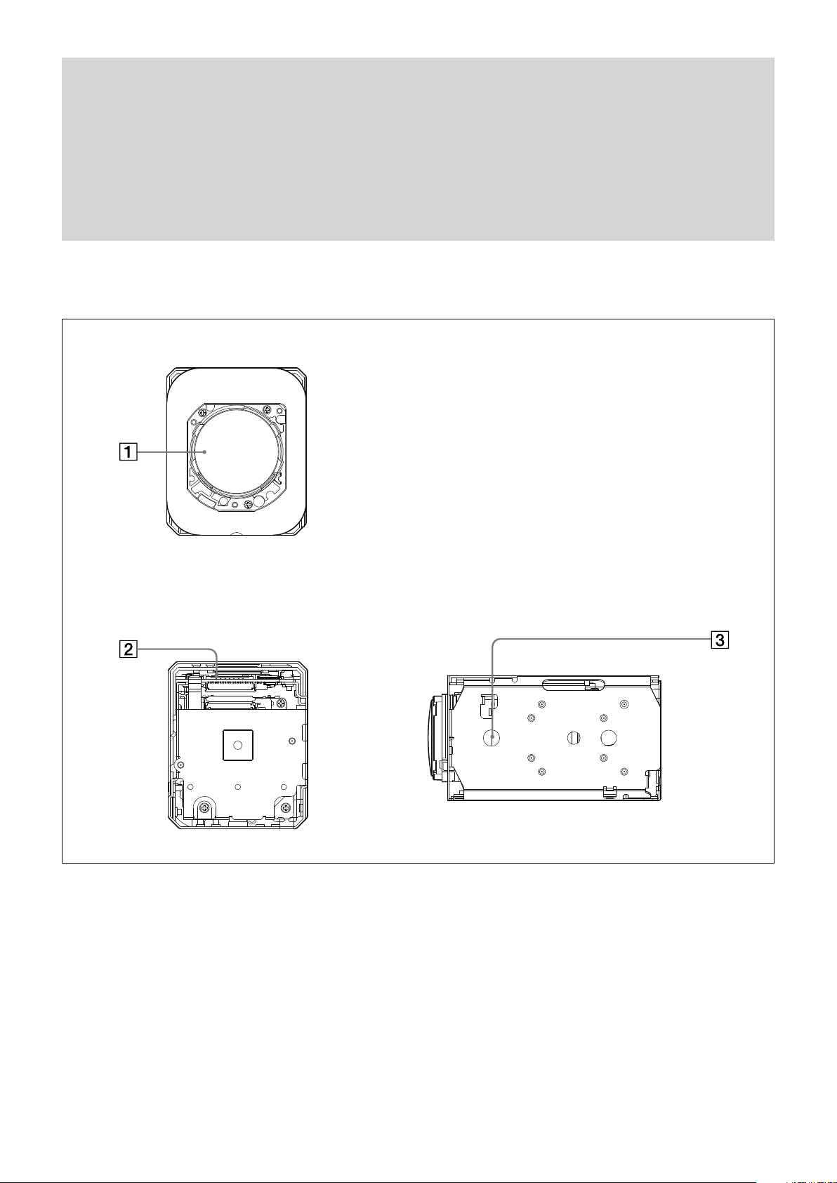
Front
Locations of Controls
Back
Lens
CN1701 connector
Tripod screw hole
When a tripod is used, please use 6 mm (
Also, please be sure to attach the tripod securely.
Bottom
1
/4 in.) or less screw to attach it to the camera.
5

Basic Functions
Overview of Functions
The camera control is performed by VISCA and PTP
commands. For the camera control by PTP, refer to
"Camera control PTP".
In general
• Power On/Off
Powers the camera on and off.
Although the screen is set non-displayed when the
power is off, the camera is able to accept VISCA
Command.
• I/F Clear
Clears the Command buffer of the FCB camera.
• Address Set
VISCA is a protocol, which normally supports a daisy
chain of up to seven connected cameras via RS-232C
interface. In such cases, the address set command can
be used to assign addresses from 1 to 7 to each of the
seven cameras, allowing you to control the seven
cameras with the same personal computer.
Although the FCB camera does not support direct
connection of cameras in a daisy chain, be sure to use
the address set command to set the address whenever
a camera is connected for the first time.
• ID Write
Sets the camera ID.
• Mute
Blanks the screen and sends out a synchronizing
signal.
• Lens Initialize
Initializes the zoom and focus of the lens. Even when
power is turned on, it initializes the zoom and the
focus.
• APR (Auto Pixel Restoration)
During operation of the FBC camera, the temperature
of the set rises and white flecks may be generated on
the CMOS image sensor.
The APR detects and corrects the white flecks,
making them unnoticeable.
The detection function of the APR needs to be done
while white flecks are generating.
If white flecks are not being generated, such as when
the temperature of the camera is not high
immediately after the set turns on, previously
generated white flecks cannot be detected even if the
APR is used. Therefore, please be sure to use the APR
while white flecks are generating.
By turning on the APR and turning the power OFF/
ON, white flecks are detected and corrected, and then
recorded in the set.
Please be sure to turn "APR" to OFF when the APR
correction is completed. The correction data is
maintained even if "APR" is OFF.
Zoom
The FCB camera incorporates a 20× optical zoom lens
combined with a digital zoom function; this camera
allows you to zoom up to 240×.
• Optical 20×, f = 4.4 mm to 88.4 mm (F 2.0 to F 3.8)
The zoom magnification can be set in the following
methods.
Using Standard Mode
Using Variable Mode
There are eight levels of zoom speed.
In these standard and variable modes, it is necessary to send
Stop Command to stop the zoom operation.
Direct Mode
Setting the zoom position enables quick
movement to the designated position.
Digital Zoom
There are three types of zoom modes; OFF,
combined mode and separate mode.
Combined Mode
This is the previously existing zoom method.
After the optical zoom has reached its
6

maximum level, the camera switches to Digital
Zoom Mode.
Separate Mode
In this mode, Optical Zoom and Digital Zoom
can be operated separately. You can use digital
zoom magnification at any time from within
any level of optical magnification.
In the combined mode, the digital zoom range
can be set.
Super Resolution Zoom
Through the use of “all pixel super resolution
technology” developed by Sony Corporation,
this product provides superior images while
maintaining the resolution without degrading
image quality, even when magnified. By
combining with optical zoom 20×, zoom is
achieved up to 30× in 4K and 40× in FHD.
About Continuous Zoom Position Reply
With ZoomDirect mode, or when zooming according
to a preset, the camera outputs zoom position data
when Continues Zoom Position Reply is set to On via a
command.
Continues Zoom Position Reply: y0 07 04 69 0p 0p 0q
0q 0q 0q FF
pp: D-Zoom Position
qqqq: Zoom Position
Focus
Focus has the following modes.
- Normal
Reaches the highest focus speed quickly. Use this
when shooting a subject that moves frequently.
Usually, this is the most appropriate mode.
- Low
Improves the stability of the focus. When the
lighting level is low, the AF function does not take
effect, even though the brightness varies,
contributing to a stable image.
• Manual Focus Mode
Manual Focus has both a Standard Mode and a
Variable Mode. Standard Mode focuses at a fixed rate
of speed. Variable Mode has eight speed levels.
In these standard and variable modes, it is necessary to send Stop
Command to stop the zoom operation.
• One Push Trigger Mode
When a Trigger Command is sent, the lens moves to
adjust the focus for the subject. The focus lens then
holds that position until the next Trigger Command is
input.
• Near Limit
Can be set in a range from 1000 (∞) to F000 (80 mm).
Initial setting: B000h (35 cm)
• Spot focus mode
The spot focus mode allows you to focus on a specific
portion of the subject. This mode is used when it is
difficult to focus on the subject by using the normal
auto focus, and so on. The focusing spot is specified
by the area of the entire screen divided into 16-split
both vertically and horizontally.
• Auto Focus Mode
The Auto Focus (AF) function automatically adjusts
the focus position to maximise the high frequency
content of the picture in a center measurement area,
taking into consideration the high luminance and
strong contrast components.
The minimum focus distance is 80 mm at the optical
wide end and 800 mm at the optical tele end.
- Normal AF Mode
This is the normal mode for AF operations.
- Interval AF Mode
The mode used for AF movements carried out at
particular intervals. The time intervals for AF
movements and for the timing of the stops can be
set in one-second increments using the Set Time
Command. The initial setting for both is set to 5
seconds.
- Zoom Trigger Mode
When zoom position is changed,it becomes AF
mode during the pre-set value (initial setting is set
to 5 seconds). Then it stops.
• AF Sensitivity
The switching of AF sensitivity can be set.
White Balance (WB)
White Balance has the following modes.
• Auto
This mode computes the white balance value output
using color information from the entire screen. It
outputs the proper value using the color temperature
radiating from a black subject based on a range of
values from 2500K to 7500K.
This mode is the initial setting.
• ATW
Auto Tracing White balance (2000K to 10000K)
• Indoor
3200K Base Mode
• Outdoor
5800K Base Mode
• One Push WB
The One Push White Balance mode is a fixed white
balance mode that may be automatically readjusted
only at the request of the user (One Push Trigger),
assuming that a white subject, in correct lighting
7

conditions, and occupying more than 1/2 of the
image, is submitted to the camera.
One Push White Balance data is lost when the power
is turned off. If the power is turned off, reset One
Push White Balance.
• Manual WB
This is a mode that enables you to manually set the
control of R and B gain up to 256 steps.
• Outdoor Auto
This is an auto white balance mode specifically for
outdoors. It allows you to capture images with natural
white balance in the morning and evening.
• Sodium Vapor Lamp Auto
This is an auto white balance mode that is compatible
with sodium vapor lamps.
• Sodium Vapor Lamp
This is a fixed white balance mode specifically for
sodium vapor lamps.
• Sodium Vapor Lamp Outdoor Auto
This is an auto white balance mode specifically for
outdoors, which is compatible with sodium vapor
lamps.
Note
High-pressure sodium lamps are supported. Proper
white balance may not be captured for some subjects
when using low-pressure sodium lamps.
Auto Exposure Mode (AE)
A variety of AE functions are available for optimal
output of subjects in lighting conditions that range
from low to high.
• Full Auto
Iris, Gain and Shutter Speed can be set automatically.
• Gain Limit Setting
The gain limit can be set at Full Auto, Shutter Priority,
Iris Priority, Bright, Spot Exposure and Manual in AE
mode. Use this setting when you want to obtain
images with a focus on the signal-to-noise ratio.
• Shutter Priority
Adjust with Variable Shutter Speed (1/1 to 1/10,000
sec., 16 high-speed shutter speeds plus 12 low-speed
shutter speeds), Auto Iris and Gain.
1) Flicker in the East Japan area (50 Hz power supply frequency)
can be eliminated by setting shutter to 1/100s.
• Iris Priority
Adjust with Variable Iris (F2.0 to Close, 22 steps),
Auto Gain and Shutter speed
1)
• Gain
Adjust with Variable Gain (0 to 36 dB, 13 steps, 38
steps on High sensitivity mode), Auto Iris and Shutter
speed
• Manual
Adjust with Variable Shutter speed, Iris and Gain
• Bright
Adjust with Variable Iris and Gain (Close to F2.0, 34
steps and High Sensitivity Mode at 38 steps)
AE – Shutter Priority
The shutter speed can be set freely by the user to a total
of 28 steps – 16 high speeds and 12 low speeds. When
the slow shutter is set, the speed can be adjusted
according to subject brightness. The picture output is
read at a normal rate from the memory. The memory is
updated at a low rate from the CMOS. AF following
capability is lowered and also the number of frame to
be displayed is decreased.
In high speed mode, the shutter speed can be set up to
1/10,000s. The iris and gain are set automatically,
according to the brightness of the subject.
Data 59.94/29.97 mode 50/25 mode 23.98 mode
21 1/10000 1/10000 1/10000
20 1/6000 1/6000 1/4800
1F 1/4000 1/3000 1/2400
1E 1/3000 1/2500 1/1200
1D 1/2000 1/1750 1/576
1C 1/1500 1/1250 1/400
1B 1/1000 1/1000 1/288
1A 1/725 1/600 1/200
19 1/500 1/425 1/192
18 1/350 1/300 1/144
17 1/250 1/215 1/120
16 1/180 1/150 1/100
15 1/125 1/120 1/96
14 1/100 1/100 1/60
13 1/90 1/60 1/50
12 1/60 1/50 1/48
11 1/50 1/30 1/40
10 1/30 1/25 1/25
0F 1/20 1/20 1/24
0E 1/15 1/15 1/20
0D 1/10 1/12 1/12
0C 1/8 1/8 1/8
0B 1/6 1/6 1/6
0A 1/4 1/4 1/4
9 1/3 1/3 1/3
8 1/2 1/2 1/2
7 2/3 2/3 2/3
6 1/1 1/1 1/1
8
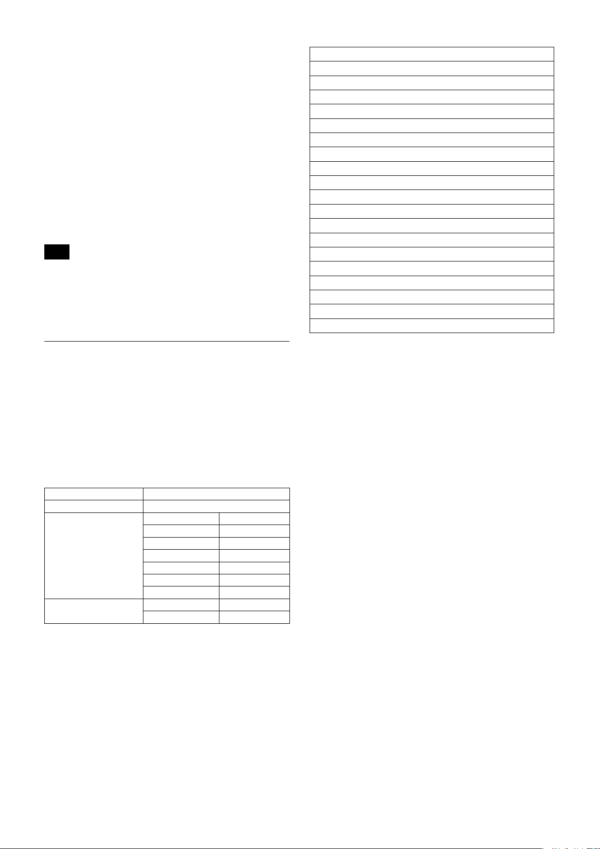
AE – Iris Priority
MIN
MAX
AGC
CLOSE
OPEN
Iris
The iris can be set freely by the user in 22 steps
between F2 and Close.
The gain and shutter speed are set automatically
according to the brightness of the subject.
Data
19 F2 0E F5.2
18 F2.2 0D F5.6
17 F2.4 0C F6.2
16 F2.6 0B F6.8
15 F2.8 0A F7.3
14 F3.1 09 F8
13 F3.4 08 F8.7
12 F3.7 07 F9.6
11 F4 06 F10
10 F4.4 05 F11
0F F4.8 00 CLOSE
Setting value
Data
Setting value
AE – Manual
The shutter speed (28 steps), iris (22 steps) and gain
(17 steps) can be set freely by the user.
Data Iris Gain Data Iris Gain
29* F2.0 48 dB 16 F2.6 0 dB
28* F2.0 45 dB 15 F2.8 0 dB
27* F2.0 42 dB 14 F3.1 0 dB
26* F2.0 39 dB 13 F3.4 0 dB
25 F2.0 36 dB 12 F3.7 0 dB
24 F2.0 33 dB 11 F4 0 dB
23 F2.0 30 dB 10 F4.4 0 dB
22 F2.0 27 dB 0F F4.8 0 dB
21 F2.0 24 dB 0E F5.2 0 dB
20 F2.0 21 dB 0D F5.6 0 dB
1F F2.0 18 dB 0C F6.2 0 dB
1E F2.0 15 dB 0B F6.8 0 dB
1D F2.0 12 dB 0A F7.3 0 dB
1C F2.0 9 dB 9 F8.0 0 dB
1B F2.0 6 dB 8 F8.7 0 dB
1A F2.0 0 dB 7 F9.6 0 dB
19 F2.0 0 dB 6 F10 0 dB
18 F2.2 0 dB 5 F11 0 dB
17 F2.4 0 dB 00 CLOSE 0 dB
*When high sensitivity mode is on.
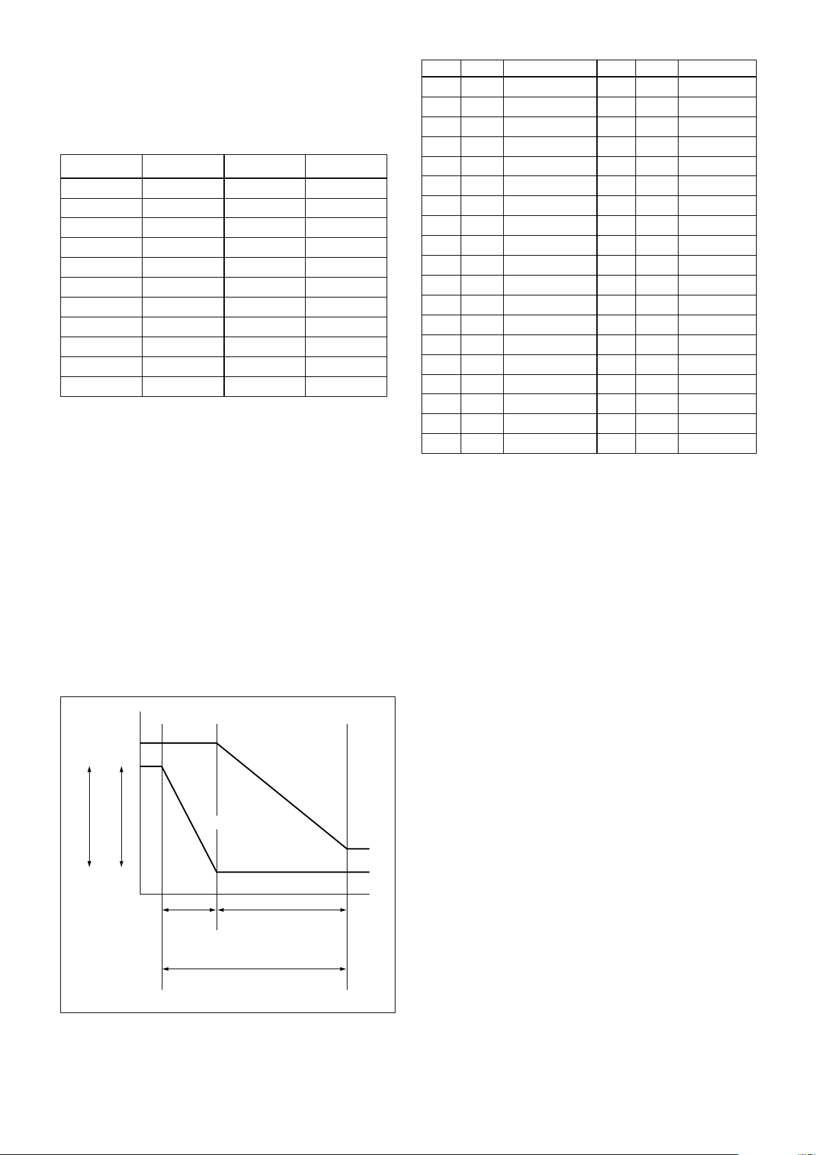
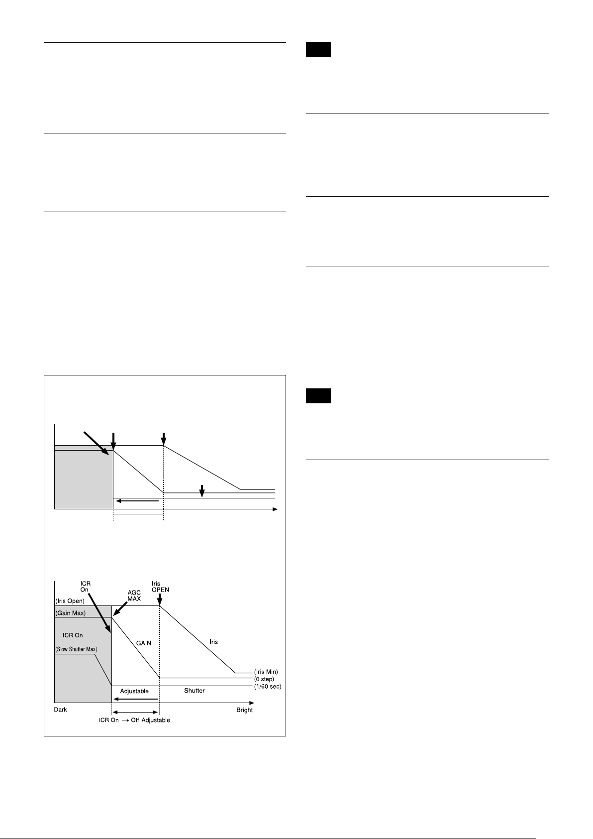
AE – Bright
The bright control function adjusts both gain and iris
using an internal algorithm, according to a brightness
level freely set by the user. Exposure is controlled by
gain when dark, and by iris when bright.
As both gain and iris are fixed, this mode is used when
exposing at a fixed camera sensitivity. When switching
from Full Auto or Shutter Priority Mode to Bright
Mode, the current status will be retained for a short
period of time.
Only when the AE mode is set to “Full Auto” or
“Shutter Priority,” can you switch it to “Bright.”
Gain
Iris curve
Gain curve
Dark Bright
Controlled
by gain
Bright limit which controllable
for this unit
Controlled by Iris
When switching from the Shutter Priority mode to the
Bright mode, the shutter speed set in the Shutter
Priority mode is maintained.
Gain Limit Setting
The gain limit can be set at the Full Auto, Shutter
Priority and Iris Priority of the Auto Exposure Mode.
Use this setting when you want to obtain image in
which signal-to-noise ratio is particularly important.
Gain Point Setting
Set the Gain Point in the middle between 0dB and gain
limit. The shutter speed can be changed from the point
when the set gain value is reached. When you want to
obtain the motion-priority image, use this setting.
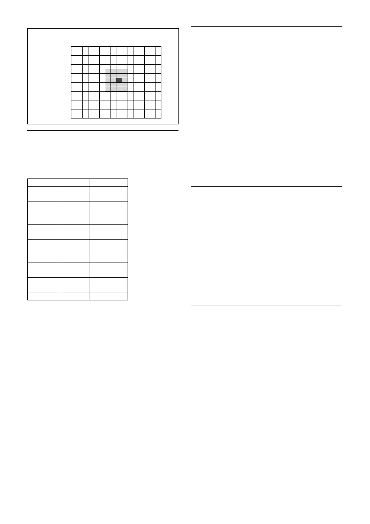
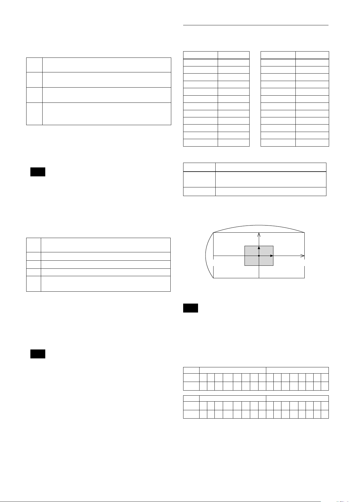
Spot Exposure Mode
In Full Auto AE, the level for the entire screen is
computed and the optimum Auto Iris and Gain levels
are determined. In Spot AE, a particular section of the
subject can be designated, and then that portion of the
image can be weighted and a value is computed so that
the Iris and Gain can be optimized to obtain an image.
For example, in an image with a lot of movement and
with varying levels of brightness, portions without
much change can be designated as such a “spot,” and
changes to the screen can be minimized in that area.
As shown in the diagram below, a range of 16 blocks
vertically and 16 blocks horizontally can be designated.
The level is calculated by the value of the surrounding
blocks (shaded) including the designated center block
(black). The range of the Spot AE frame is fixed to 5
blocks vertically and 4 blocks horizontally.
9
(8,7)
Horizontal 16
Vertical 16
0
0
1
2
3
4
5
6
7
8
9
A
B
C
D
E
F
1 2 3 4 5 6 7 8 9 A B C D E F
Exposure Compensation
Exposure compensation is a function which offsets the
internal reference brightness level used in the AE
mode, by steps of 1.5 dB.
High Resolution Mode
This mode enhances edges and produces higher
definition images.
Aperture Control
Aperture control is a function which adjusts the edge
enhancement of objects in the picture.
When it is set to Auto, the adjustment is performed
automatically.
When it is set to Manual, you can adjust multiple
setting items. Sometimes, the noise particle that is
generated when the gain is increased becomes
noticeable because its edge is enhanced by this
function. In this case, lower the edge enhancement
level or adjust the edge enhancement amount of noise
by “Crispening”.
Data Step
0E +7 +10.5 dB
0D +6 +9 dB
0C +5 +7.5 dB
0B +4 +6 dB
0A +3 +4.5 dB
09 +2 +3 dB
08 +1 +1.5 dB
07 0 0 dB
06 −1 −1.5 dB
05 −2 −3 dB
04 −3 −4.5 dB
03 −4 −6 dB
02 −5 −7.5 dB
01 −6 −9 dB
00 −7 −10.5 dB
Setting value
Slow AE (Auto Exposure)
The slow AE Response function allows you to reduce
the exposure response speed. Usually the camera is set
up so that the optimum exposure can be obtained
automatically within about 1 second. However, using
the slow AE response function allows you to lengthen
the auto exposure response speed from the initial setup
speed (01h) to approx. 10 minutes (30h) (at normal
shutter speed).
For example, with the normal setting (about 1 second),
if the headlights of a car are caught by the camera, the
camera automatically adjusts the exposure so that it can
shoot a high-intensity subject (in this case, the
headlights). As a result, images around the headlights,
that is, the rest of the subject, except the headlights,
becomes relatively dark, and poorly distinguished.
However, using the slow AE function means the AE
response speed will be slower, and response time will
be longer. As a result, even if the camera catches a highintensity subject (e.g., the headlights) for a moment,
you can still easily distinguish the portions of the image
surrounding the headlights.
Backlight Compensation
When the background of the subject is too bright, or
when the subject is too dark due to shooting in the AE
mode, back light compensation will make the subject
appear clearer.
Visibility Enhancer (VE)
Depending on the imaging scene, the Visibility
Enhancer function makes the darker part of a camera
image brighter, and automatically correct brightness
and contrast to show bright parts clearly.
Defog mode
When the surrounding area of the subject is foggy and
low contrast, the defog mode will make the subject
appear clearer.
You can select four levels for this function: OFF, Low,
Middle and High.
Highlight Compensation (HLC)
HLC (highlight correction) is a function to adjust AE
and AF, and to perform the masking of light area as
required when a high intensity spot light is detected.
It allows you to easily read the number of vehicles and
number plate in the indoor parking area or in the
outdoor during the night.
10
Maximum Shutter Limit
The brighter the object is, the shutter speed will
increase. This is the function to set the upper limitation
on the shutter speed. This will help to make images
smooth with less inconsistent motions when you shoot
bright objects.
Grayscale image
(256 levels)
Color image
Minimum Shutter Limit
When the subject becomes dark, the shutter speed
becomes slow and the gain is increased. This is a
function to put a limit on the shutter speed.
It prevents the camera shake when you shoot a moving
subject in a dark place.
Noise Reduction (NR)
The NR function removes noise (both random and
non-random) to provide clearer images.
This function has six steps: levels 1 to 5, plus off.
The NR effect is applied in levels based on the gain,
and this setting value determines the limit of the effect.
In bright conditions, changing the NR level will not
have an effect.
When it is set to level 7Fh, you can set NR of 2D/3D
individually.
High Sensitivity Mode
In this mode, the maximum gain increases, enabling to
obtain a brighter output even in a darker environment.
However, if the gain reaches high level, the image will
have a large amount of noise.
Variable Gamma Mode
Standard (00h), straight gamma (01h), 512 pattern
(02h) are available for setting.
Binarization
process
Note
Flicker on images with color enhancement is not a malfunction of
the camera. Flicker can be reduced by setting the threshold level
and the aperture control.
Assign any
color
Temperature Reading Function
The conversion value (hex) of the temperature sensor
built into to the camera can be read by using a query
command. The conversion value has an error of ±3 C,
and because the temperature sensor is inside the
camera, this value is not the ambient temperature. Use
it as a reference value.
Slow Shutter On/Off
When set to “On,” the slow shutter functions
automatically when the light darkens. This setting is
available only when the AE mode is set to “Full Auto.”
The initial setting is “Auto Slow Shutter Off.”
Low-Illumination Chroma Suppress Mode
You can configure a chroma suppress mode for lowillumination conditions. This can be useful when color
noise is particularly noticeable in such conditions.
Four levels (disabled and three levels) are available for
the low-illumination chroma suppress mode.
Gamma Offset
You can set the brightness from –16 (00h) to +64 (40h)
in each mode of the variable gamma mode.
Color Enhancement
The shot color image can be output in any two colors in
the grayscale image based on the density level (brighter
or darker than the threshold value) of the image
portion.
(The threshold level can be set with an optional level.)
ICR (IR Cut-Removable) Mode
The IR Cut-Filter installed in front of the CMOS image
sensor can be engaged or disengaged by the mechanical
structure. The sensitivity in the infrared region is
increased by disengaging the IR Cut-Filter, allowing the
camera to capture the image in darker places. When
the auto ICR mode is set to On, the image becomes
black and white.
11
Custom Color Gain
ICR
Shutter
Dark Bright
AGC
MAX
Iris
OPEN
Shutter 1/60 sec
ICR Off On
GAIN
ICR On
Iris
You can configure the color gain. Use this setting when
bright color is particularly important.
The initial setting 100% (4h) can be set to range from
approx. 60% (0h) to 200% (Eh) with 15 stages.
Note
Depending on the information such as brightness, etc., in the On/
Off settings condition, a malfunction may occur when the subjects
largely consisting of blue and green colors are taken.
Camera ID
Custom Color Phase
You can configure the color phase. The initial setting 0
degrees (7h) is adjustable between approx. −14 degrees
(0h) to +14 degrees (Eh), in 15 increments.
Auto ICR Mode
Auto ICR Mode automatically switches the settings
needed for attaching or removing the IR Cut Filter.
With a set level of darkness, the IR Cut Filter is
automatically disabled (ICR On), and the infrared
sensitivity is increased. With a set level of brightness,
the IR Cut Filter is automatically enabled (ICR Off).
Also, on systems equipped with an IR light, the internal
data of the camera is used to make the proper decisions
to avoid malfunctions.
Auto ICR Mode operates with the AE Full Auto setting.
When Auto Slow Shutter is Off (initial setting)
The ID can be set up to 65,536 (0000h to FFFFh). As
this will be memorized in the nonvolatile memory
inside, data will be saved.
Picture Effect
It consists of the following function.
• Black & White: Monochrome Image
Image stabilizer
When the image stabilizer function is set to On, you
can obtain the image with less screen blur caused by
shaking and so on. The correction effect can be
achieved at the vibration frequency around 10 Hz. The
image stabilizer function uses the digital zoom method.
Although there are changes in the angle of view and
resolution, the sensitivity is maintained.
Note
The image stabilizer function may not work under the environment
of high frequency vibration components. When using the camera
under such environment, set the image stabilizer function to Off.
When Auto Slow Shutter is On
"StableZoom"
"StableZoom" is a function to perform correction using
the image stabilizer function according to the zoom
magnification and zoom the image up to approx. 24×
smoothly by combining the optical zoom with the
digital zoom. By zooming the image furthermore using
the digital zoom, the image is zoomed up to 288×. On
the wide side, the image without the deterioration in
resolution can be obtained because the digital zoom is
not used. On the other hand, the correction effect by
the image stabilizer function is maximized on the tele
side, reducing the blur.
"StableZoom" can be set to On/Off by the register
setting.
12
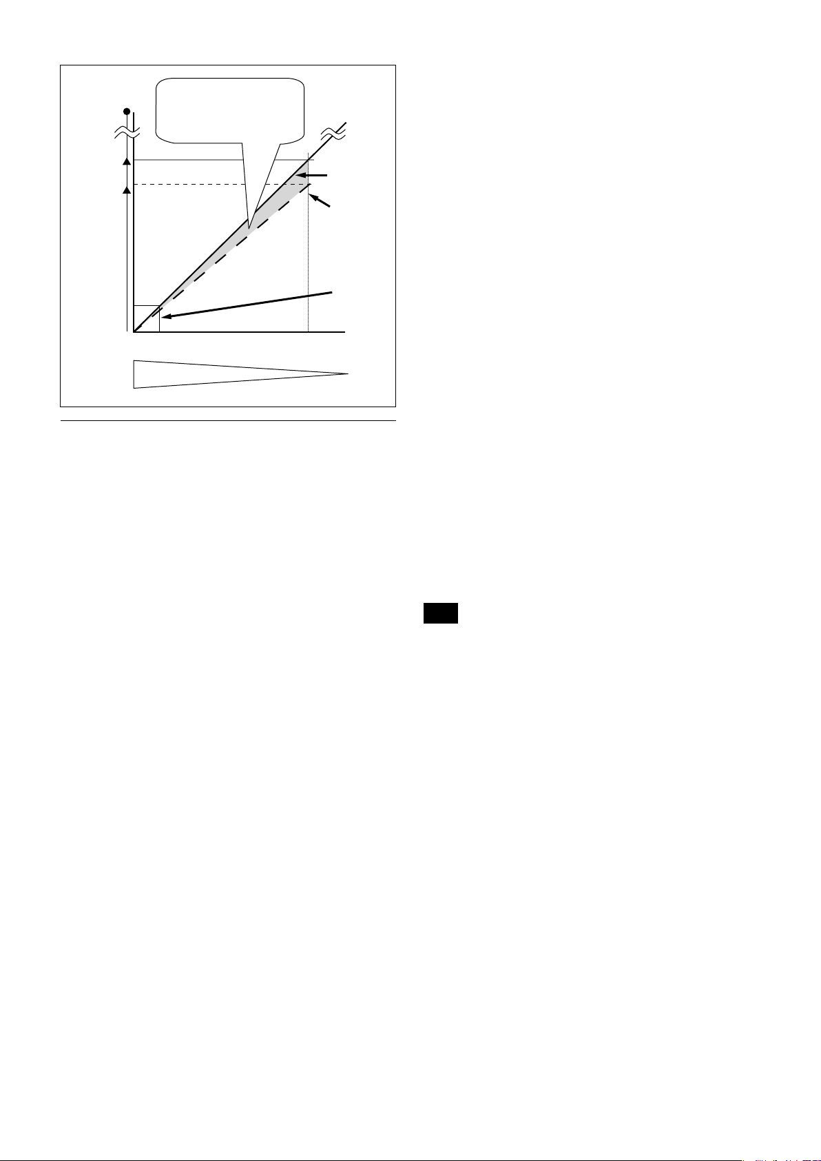
288×
20×
Zoom
magnification
Approx.
24×
wide
Angleofview・resolution
Opticalzoom
position
tele
Digitalzoom
isnotusedon
thewideside.
Opticalzoom
Digitalzoom
+
StableZoom
Correctionisperformed
fortheblurinthisdigital
zoomarea.
Others
E-FLIP
This function reverses the video output from the
camera vertically and horizontally.
• Zoom Position
Digital Zoom On/Off/Super Resolution Zoom
•
Focus Auto/Manual
•
Focus Position
•
AE Mode
•
Shutter control parameters
•
Bright Control
•
Iris control parameters
•
Gain control parameters
•
Exposure Compensation On/Off
•
Exposure Level
•
Backlight Compensation On/Off
•
Slow Shutter On/Off
•
White Balance
•
R/B Gain
•
Aperture Control
•
ICR On/Off
•
Defog
•
Custom Preset
As with the position preset function, the camera
shooting conditions can be stored and recalled. The
settings are recalled when the power is turned on.
For setting items, see the “Initial Settings, Custom Preset
and Backup” section on page 24.
LR Reverse
This function reverses the video output from the
camera horizontally.
Freeze
This function captures an image in the field memory of
the camera so that this image can be output
continuously.
Because communication inside the camera is based on V cycle,
the captured image is always the one 3V to 4Vs after the
sending of a Command. Thus, you can not specify a time
period after sending EVEN, ODD or a Command.
Electronic Pan/Tilt
In 4K (3840 × 2160) mode, crop the image at the
designated position to Full HD (1920 × 1080) and
display.
You can specify the central coordinate of cropped
images by commands. Cropped sizes cannot be
changed as it is fixed to FHD.
Memory (Position preset)
Using the position preset function, 16 sets of camera
shooting conditions can be stored and recalled.
This function allows you to achieve the desired status
instantly, even without adjusting the following items
each time.
User Memory Area
A user area of 16 bytes allows you to write data, such as
an ID for each customer, data for each system, and so
on, freely.
Note
Rewriting of memory is not unlimited. Be careful to avoid using the
memory area for such as unnecessary tasks as rewriting the
contents of the memory for every operation.
Register Setting
The camera’s initial settings can be changed by the
register setting command.
Register Setting Command:
8x 01 04 24 mm 0p 0q FF
mm: Register No. (=00 to 7F)
pq: Register Value (=00 to FF)
Register Inquiry Command:
8x 09 04 24 mm FF
mm: Register No.
y0 50 0p 0p FF
pp: Register Value
(returned from the camera)
The register setting items and No. are as follows.
For details, see “Register Setting” on page 55.
Baud Rate: 00
Communication speed can be changed.
Monitoring Mode: 72
The output mode can be set.
13
Zoom Limit: 50 (wide end), 51 (tele end)
The wide and tele zoom limits can be set.
D-Zoom Max: 52
The maximum digital zoom limit can be set (initial
settinig is 12×).
FocusOffset: 55
Placing a dome cover in front of the camera may
cause the focal distance of the camera to change.
Especially at the Tele end, this effect exceeds the AF
range, so focus cannot track, although it responds
to changes in this value.
For details, see “Register Setting” on page 55.
Extended mode: 5F
ON/OFF can be set. (initial setting is OFF.)
For details, see page 17.
Note
After changing the register setting, turn off the camera, then turn it
on again.
Privacy Zone Masking Settings
For details, see page 15.
00 01 02 03 04 05 06 07
A B C D E F G H
08 09 0A 0B 0C 0D 0E 0F
I J K L M N O P
10 11 12 13 14 15 16 17
Q R S T U V W X
18 19 1A 1B 1C 1D 1E 1F
Y Z & ? ! 1 2
20 21 22 23 24 25 26 27
3 4 5 6 7 8 9 0
28 29 2A 2B 2C 2D 2E 2F
À È Ì Ò Ù Á É Í
30 31 32 33 34 35 36 37
Ó Ú Â Ê Ô Æ Ã
38 39 3A 3B 3C 3D 3E 3F
Õ Ñ Ç ß Ä Ï Ö Ü
40 41 42 43 44 45 46 47
Å $ ¥ £ ¿ ¡
48 49 4A 4B 4C 4D 4E 4F
ø ” : ’ . , / -
Title Display
• You can set a title of up to 11 lines. One line can
contain up to 20 characters.
• You can set display on/off, the horizontal position of
the first character, blinking state and color for each
line.
• The camera gives priority to a title display when the
camera status is displayed on the relevant line. On the
lines where a title is not set, the camera status is
displayed.
Line Number 00h to 0Ah
H-position 00h to 1Fh
00h WHITE
01h YELLOW
02h VIOLET
Color
Blink
03h RED
04h CYAN
05h GREEN
06h BLUE
00h Off
01h On
14
Privacy Zone Masking Function
Privacy Zone masking protects private objects and
areas such as house windows, entrances, and exits
which are within the camera’s range of vision but not
subject to surveillance.
Privacy zone masking can be masked on the monitor to
protect privacy.
Comments: Each of 24 Privacy zones can be switched
on and off individually by a single VISCA
Command. If you want to display a Privacy zone,
you must set its bit to 1. If you do not want to
display a Privacy zone, you must set its bit to 0.
Set Mask Color
Command: 8x 01 04 78 pp pp pp pp qq rr FF
Parameter:
Features
• Mask can be set on up to 24 places according to Pan/
Tilt positions.
• Mask can be displayed on 8 places per screen
simultaneously.
• Individual on/off zone masking settings.
• Two colors can be individually set for each of
24 privacy zones.
• Interlocking control with zooming.
• Interlocking control with Pan/Tilt.
• Non-interlocking control with Pan/Tilt.
Details of Setting Commands
Set Mask
Command: 8x 01 04 76 mm nn 0r 0r 0s 0s FF
Parameters:
mm Setting Mask
See “mm: Mask setting list” in “Parameters” on page 15.
nn Selects new setting or resetting for the zone. See “nn:
Setting” in “Parameters” on page 15.
rr Sets the half value “w” of the Mask Width.
ss Sets the half value “h” of the Mask Height.
See “pp: x, qq: y, rr: w, ss: h” in “Parameters” on page 15.
Comments: To set the mask, first display the object at
the center of the screen. When “nn” is set to 1, the
current Pan/Tilt/Zoom Position is recorded in
internal memory.
When “nn” is set to 0, the Pan/Tilt/Zoom Position
in memory is not changed.
Notes
• The tilt angle at which you can set the mask is between –70 to
+70 degrees.
• It is recommended that you set the size to at least twice the size
of the object (height and width).
pp pp pp pp Each 24 Privacy Zones correspond to the BIT.
See “pp pp pp pp: Mask bit” in “Parameters” on
page 16.
qq Set the color code
rr Set the color code. See “qq, rr: Color code” in
“Parameters” on page 17.
Comments: Two different color masks can be chosen.
Two colors can be individually set for each of
24 privacy zones.
If the bit of parameter (pp pp pp pp) is set to “0”,
mask color will be “qq” color (Color code). If the
bit of parameter (pp pp pp pp) is set to “1”, the
mask color will be “rr” color (Color code).
Example: 8x 01 04 78 00 00 00 03 00 07 FF
The mask color of Mask_A and Mask_B is White
(color code 07h), and the mask color of the other
Mask (C to X) is Black (color code 00h).
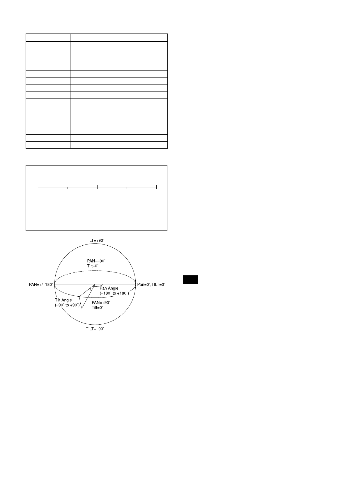
Set Pan Tilt Angle
Command: 8x 01 04 79 0p 0p 0p 0q 0q 0q FF
Parameter:
ppp Pan Angle
qqq Tilt Angle
See “Setting pan/tilt angle” in “Parameters” on
page 16.
Comments: Pan/Tilt angle settings are hexadecimal
data.
The resolution of Pan/Tilt angle is 0.088 degrees.
Notes
• When you set the pan/tilt angle, locate the pan/tilt position at
the center point of the FCB camera’s position.
• If you set the pan/tilt angle or zoom the camera, a bigger mask
will be displayed for about one second.
Set Display
Command: 8x 01 04 77 pp pp pp pp FF
Parameter:
pp pp pp pp Each 24 Privacy Zones corresponds to the BIT.
See “pp pp pp pp: Mask bit” in “Parameters” on
page 16.
15
Set PTZ Mask
160
90
0h(x,y)
w
B0h
D3h
2Dh
50h
Command: 8x 01 04 7B mm 0p 0p 0p 0q 0q 0q 0r 0r
0r 0r FF
Parameter:
mm Setting Mask
See “mm: Mask setting list” in “Parameters” on page 16.
ppp Pan Angle (000 to FFF)
See “Setting pan/tilt angle” in “Parameters” on page 16.
qqq Tilt Angle (000 to FFF)
See “Setting pan/tilt angle” in “Parameters” on page 16.
rrrr Zoom Position (000 to 4000)
See “Zoom Ratio and Zoom Position (for reference)” on
page 53.
Comments: Mask can be set at the desired position
by setting the pan tilt angle and zoom position
using this command. The set value can be input by
hexadecimal number.
Note
Privacy mask zone follows the change of angle of view according
to zoom. However, the follow might be delayed for a moment if
there is any big change, such as when using D-Zoom or E-FLIP.
Parameters
mm: Mask setting list
Mask Name mm (Hex) Mask Name mm (Hex)
Mask_A 00h Mask_M 0Ch
Mask_B 01h Mask_N 0Dh
Mask_C 02h Mask_O 0Eh
Mask_D 03h Mask_P 0Fh
Mask_E 04h Mask_Q 10h
Mask_F 05h Mask_R 11h
Mask_G 06h Mask_S 12h
Mask_H 07h Mask_T 13h
Mask_I 08h Mask_U 14h
Mask_J 09h Mask_V 15h
Mask_K 0Ah Mask_W 16h
Mask_L 0Bh Mask_X 17h
nn:Setting
nn Setting
00h Resetting the zone size (the value of w,h)
for the existing mask.
01h Setting newly the zone size (the value of w,h).
Non Interlock Mask
Command: 8x 01 04 6F mm 0p 0p 0q 0q 0r 0r 0s 0s
FF
Parameters:
mm Setting Mask
See “mm: Mask setting list” in “Parameters” on page 15.
pp Sets the center position “x” of the Mask on screen.
qq Sets the center position “y” of the Mask on screen.
rr Sets the half value “w” of the Mask Width.
ss Sets the half value “h” of the Mask Height.
See “pp: x, qq: y, rr: w, ss: h” in “Parameters” on page 15.
Commands: Mask does not interlock with pan/tilt.
The limitations of parameters are as follows.
(hexadecimal representation)
x: ±50h
w: ±50h
y: ±2Dh
h: ±2Dh
Note
When the Set Mask command and the Non Interlock Mask
command are set to the same mask, the command set later
becomes effective.
pp: x, qq: y, rr: w, ss: h
mask
Effective display area
Note
The priority order of the mask display is in the sequence from A
(highest) to X (lowest).
When you set the parameters of masks non-sequentially, it is
recommended that you set the mask whose priority order is higher,
first.
pp pp pp pp: Mask bit
pp pp
bit 7 6 5 4 3 2 1 0 7 6 5 4 3 2 1 0
Mask - - X W V U T S - - R Q P O N M
pp pp
bit 7 6 5 4 3 2 1 0 7 6 5 4 3 2 1 0
Mask - - L K J I H G - - F E D C B A
The “-” must be “0”.
16
qq, rr: Color code
0 90-180 -90 180
400h800h C00h 800h
Mask (color) Code (qq, rr) Translucence (qq, rr)
Black 00 h 10 h
Gray1 01 h 11 h
Gray2 02 h 12 h
Gray3 03 h 13 h
Gray4 04 h 14 h
Gray5 05 h 15 h
Gray6 06 h 16 h
White 07 h 17 h
Red 08 h 18 h
Green 09 h 19 h
Blue 0A h 1A h
Cyan 0B h 1B h
Yellow 0C h 1C h
Magenta 0D h 1D h
Mosaic 7F h
Setting pan/tilt angle
Angle/Parameter of Angle (ppp, qqq)
Set the angle resolution to 360 (degree)/4096 (1000h).
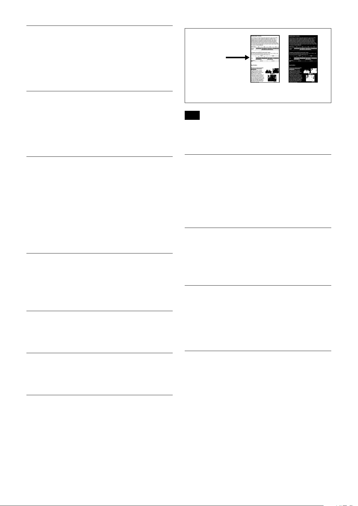
Extended Commands
Extended commands support the following functions
(described previously).
Turn on this mode (for details, see “Extended Mode” in
“Register Setting” on page 55) to enable the following
functions.
• Exposure Compensation
The setting can be set in steps of approximately 0.2dB
(-128 (00h) to approximately +127 (FFh)).
For details, see page 9.
• Aperture Control
The setting can be set to 256 levels (00h to FFh).
For details, see page 10.
• Custom Color Gain
The initial setting is 100% (80h), and the setting can
be set to 256 levels from approximately 0% (00h) to
approximately 200% (FFh).
For details, see page 11.
• Custom Color Phase
The initial setting is 0 degrees (80h), and the setting
can be set to 256 levels from approximately −14
degrees (00h) to approximately +14 degrees (FFh).
For details, see page 11.
• Auto ICR Mode
The setting of ICR ONOFF threshold can be set
when Auto ICR is on.
The setting range is 0 step (00h) to 255 step (FFh).
The setting of ICR OFFON threshold (On Level)
can be set when Auto ICR is on.
The setting range is 0 step (00h) to 28 step (1Ch).
For details, see page 12.
Note
When the extended mode is Off, CMD_NOT_EXEC will be
returned if you send the extended commands to the camera.
When the extended mode is On, CMD_NOT_EXEC will be
returned if you send the normal commands to the camera.
17
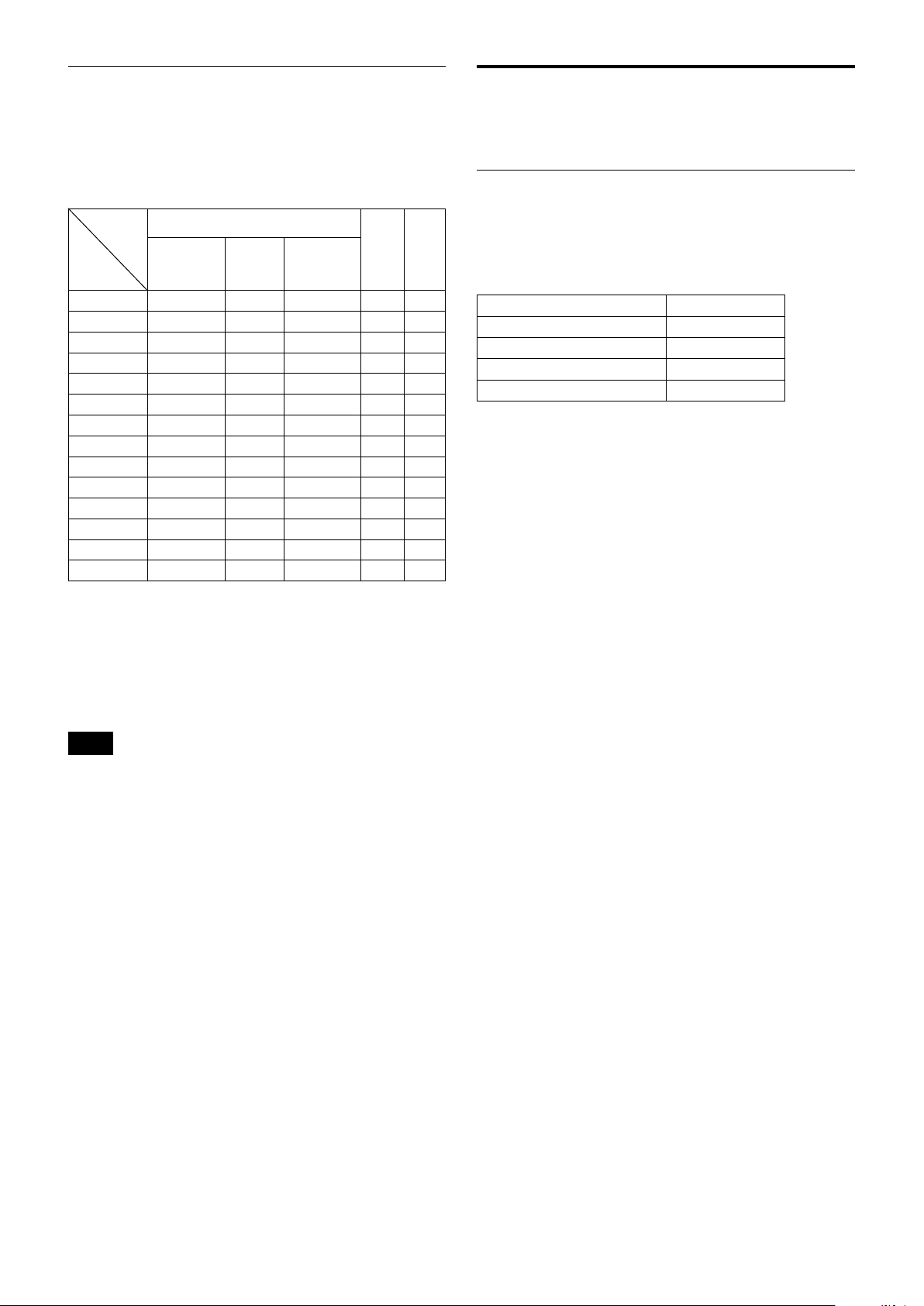
External synchronization function
(FCB-ER8550)
About the firmware
External synchronization will start when you input
synchronization signals to 15pin on CN1701.
The possible external synchronization combinations
are listed below:
Input External
Signal
format
Camera
Mode
3840×2160/29.97p
3840×2160/25p
3840×2160/23.98p
1920×1080/59.94p
1920×1080/59.94i
1920×1080/50p
1920×1080/50i
1920×1080/29.97p
1920×1080/25p
1920×1080/23.98p
1280×720/59.94p
1280×720/50p
720×480/59.94p
720×576/50p
1080/59.94i 1080/50i 1080/47.95i
Tri-State Sync
×
× ×
×
×
×
× ×
×
×
× ×
× ×
× ×
× ×
× ×
× ×
NTSC
Black
burst
× ×
× ×
× ×
× ×
× ×
× ×
PAL
Black
burst
× ×
× ×
update
Overview
This document descries detailed operation for
firmware update.
Serial Port Setting during maintenance mode
×
×
×
×
×
×
Communication Speed 115200 bps
Data bit 8 bit
Parity None
Stop bit 1 bit
Flow control None
External signal spec
• Tri-State SYNC: partial part of SMPTE 240M/274M
• NTSC Black burst: EBU N14/SMPTE RP-154/SMPTE
170M/SMPTE 318M
• PAL Black burst: ITU-R BT.470-6
The H Phase adoption function is not available.
Notes
• Once you input the external synchronization signal, do not
change the settings until the state enters the external
synchronization mode.
• If the external synchronization signal is not stable, the unit will
not enter the external synchronization mode.
• In the cases below, images or data will be disordered and may
malfunction.
– if you input signals other than the allowed external
synchronization signals.
– if you input external synchronization signals when the external
synchronization is not supported.
18
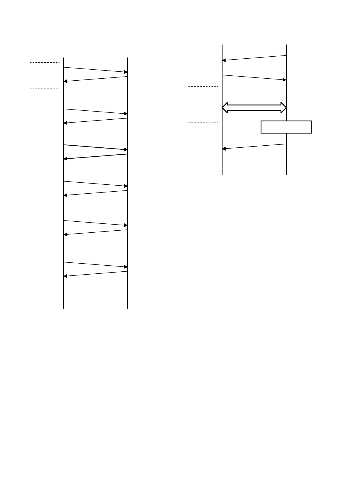
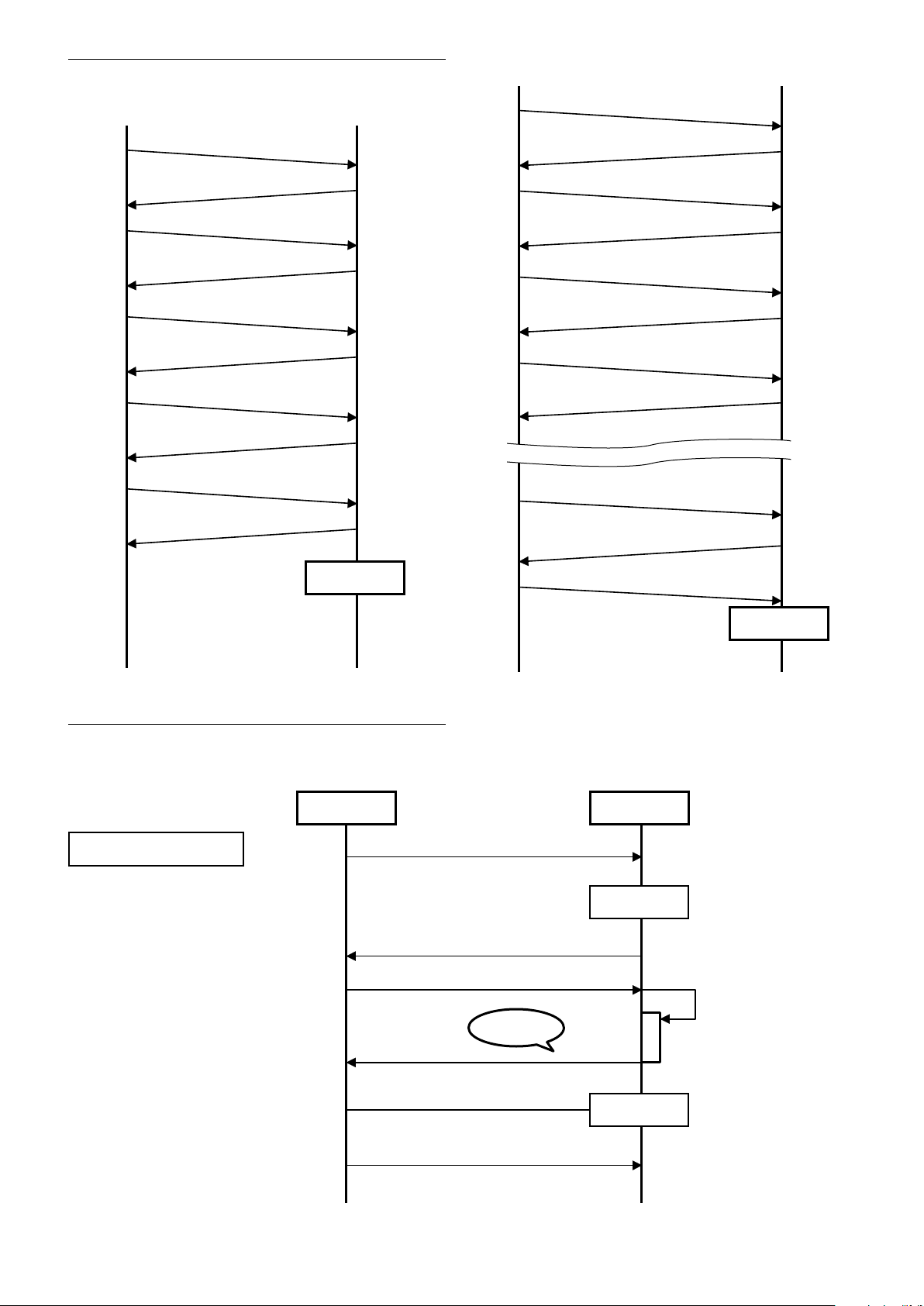
Update Procedure (UART)
HOST FCB
CAM_Power off
8x 01 04 00 03 FF
ACK, COMP
8x 01 04 00 0C FF
ACK, COMP
8x 01 04 00 0D FF
ACK, COMP
8x 01 04 00 13 FF
ACK, COMP
8x 01 04 00 04 FF
ACK, COMP
8x 01 04 00 20 FF
ACK, COMP
Enter
Standby
Mode
Enter
Maintenance
Mode
Transition to
maintenance
mode
* When power is off during this period, camera will be broken.
HOST FCB
’reboot’ + CR
“ready” + CR
“reprogram ( )” + CR
Sending firmware
* When power is off during this period, camera will be broken.
Sending Firmware Binary
with X modem protocol
Firmware Update
Ready Message
* WRITING Firmware
Enter Maintenance Mode
Maintenance Mode
19
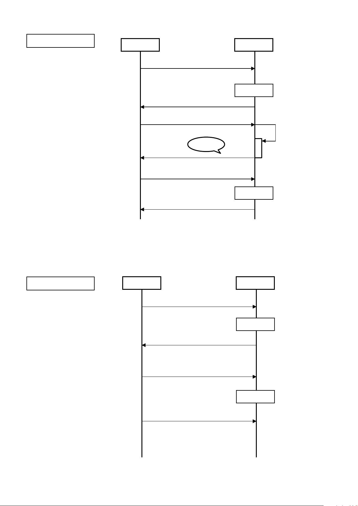
Update procedure (USB)
Reboot
CMD_GET_STATE
ERR_OK (CURSTAT_PRE_INIT)
CMD_INIT
ERR_OKP
CMD_CHK_GUARD
ERR_OK (STAT_OK)
CMD_QUERY_VERSION
ERR_OK
CMD_SWITCH_MODE
ERR_OK (STAT_OK)
HOST FCB
HOST FCB
Reboot
CMD_GET_STATE
ERR_OK (CURSTAT_PRE_SWITCTMODE)
CMD_CHK_GUARD
ERR_OK (STAT_OK)
CMD_WRITE_FIRM
ERR_OK (STAT_BUSY)
ERR_OK (STAT_BUSY)
CMD_WRITE_FIRM
CMD_WRITE_FIRM
ERR_OK (STAT_OK)
CMD_COMPLETE
FCB
Reboot
Reboot
ready
updater mode
different versions
application mode
VISCA
HOST
VISCA
xmodem
H/W RePower
Error
erroroccurs
Error occurrence patterns
The update (UART) error patterns are as follows.
UART update-error 1
Different versions
20
UART update-error 2
FCB
Reboot
Reboot
ready
updater mode
date error
updater mode
VISCA
HOST
xmodem
VISCA
H/W RePower
ready
Error
erroroccurs
FCB
Reboot
Reboot
ready
VISCA
HOST
VISCA
H/W RePower
updater mode
application mode
Error during update
UART update-error 3
No update
21
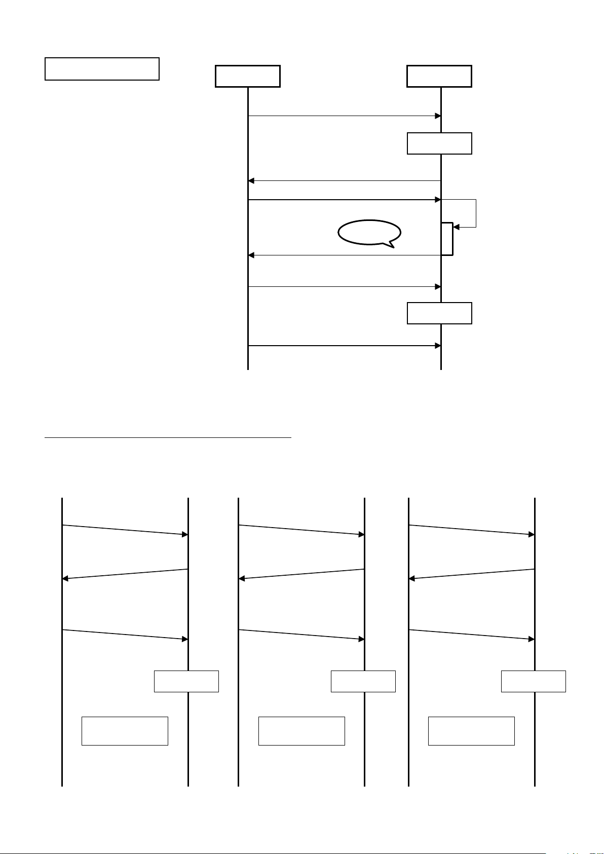
UART update-error 4
FCB
Reboot
Reboot
ready
Error
VISCA
HOST
VISCA
xmodem
H/W RePower
updater mode
updater mode
fatal error
erroroccurs
Reboot
Startinthe
applicationmode.
CMD_GET_STATE
ERR_XXXX
(Refer to the command specification.)
ERR_XXXX
(Refer to the command specification.)
ERR_XXXX
(Refer to the command specification.)
CMD_COMPLETE
HOST FCB
Startagain
fromthebeginning.
CMD_GET_STATE
CMD_COMPLETE CMD_COMPLETE
HOST FCB
Versionupgrade
iscompleted.
CMD_GET_STATE
HOST FCB
Reboot Reboot
Fatal error
Update Procedure (USB)
The update (USB) error patterns are as follows.
22
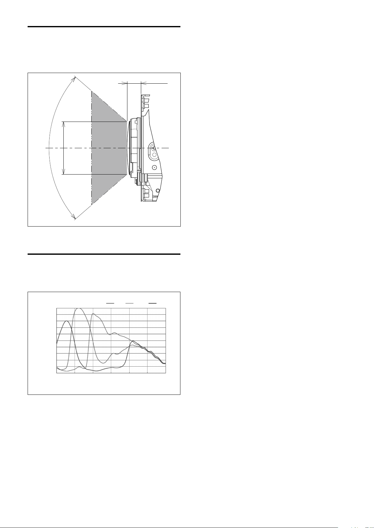
Eclipse
400 500 600 700 800 900 1000
Wavelength [nm]
0.0
0.2
0.1
0.4
0.3
0.5
0.6
0.7
0.8
0.9
1.0
Relative response [a.u.]
Red Green Blue
When designing the housing, refer to the dimensional
allowance as shown in the figure below.
7.84
81.8°
ø31.4
Spectral Sensitivity Characteristics
unit: mm
Use the graph as a reference value. (We can not
guarantee these values.)
This data is measured when the IR cut filter is removed
and the characteristics of the lens and optical source
characteristics are ignored.
23

Initial Settings, Custom Preset and Backup
Initial Settings for the various functions of the FCB
camera are indicated in the “Initial Settings” column.
The “Custom Preset” column indicates whether the
custom preset function can be used to store the
settings. The function enables the stored settings to be
recalled automatically when the camera is turned on.
The “Back up at standby” column indicates whether the
data is preserved even when the camera is in the
standby mode.
Mode/Position setting Initial Settings
Zoom Position wide end
D-Zoom On/Off Off
D-Zoom Separate/Combine Combine
D-Zoom Position 00h
Focus Position —
Focus Auto/Manual Auto
Near Limit Setting B000 (35 cm)
AF Sensitivity Normal
AF Mode Normal
AF Run Time 5 sec
AF Interval 5 sec
WB Mode Auto
WB Data (Rgain, Bgain) —
One Push WB Data —
AE Mode Full Auto
AE Response 01h
Shutter Position —
Maximum Shutter Limit 1Dh: 1/2000 (59.94 fps)
1Dh: 1/2000 (50 fps)
1Dh: 1/30 (29.97 fps)
1Dh: 1/25 (25 fps)
1Eh: 1/48 (23.98 fps)
Minimum Shutter Limit 12h: 1/60 (59.94 fps)
12h: 1/50 (50 fps)
10h: 1/30 (29.97 fps)
10h: 1/25 (25 fps)
12h: 1/48 (23.98 fps)
Color Enhancement On/Off Off
Slow Shutter Limit 0Dh: 1/10 (59.94 fps)
0Dh: 1/10 (29.97 fps)
0Dh: 1/12(50 fps)
0Dh: 1/12(25 fps)
0Dh: 1/12 (23.98 fps)
Iris Position 19h: F2.0
Gain Position 01h: 0dB
Bright Position —
Exposure Compensation On/Off Off
Exposure Compensation Amount ±0
BackLight On/Off Off
Custom
Preset
Back up
at standby
A circle “” in this column signifies that the data is preserved.
A cross “” signifies that the data IS NOT preserved.
24

Mode/Position setting Initial Settings
Spot AE On/Off Off
Spot AE Position Setting X=8, Y=8
Detail Level 07h
High Resolution Mode On/Off Off
LR Reverse On/Off Off
Freeze On/Off Off
Picture Effect Off
ICR On/Off Off
Auto ICR On/Off Off
Auto ICR Threshold Level 0Eh
Camera Memory Same as the factory value setting
Display On/Off Off
Mute On/Off Off
Auto ICR Alarm On/Off Off
NR Level 3
Image Stabilizer Off
Gain Limit Off
Color Enhancement Threshold Level
Color Enhancement High Luminance
Color Setting Y
Color Enhancement Low Luminance
Color Setting Y
Low-Illumination Chroma Suppress 1h (Low)
Color Gain 4h (100%)
Color Hue 7h (0 degrees)
Title Display On/Off Off
Title Setting —
Mask Setting —
Mask Color Setting —
Center Line Display On/Off Off
E-Flip On/Off Off
Privacy Zone On/Off Off
Privacy Zone Setting —
Camera ID 0000h
ZoomPos Continuous Output On/Off Off
ZoomPos Continuous Output Interval 3Ch
HLC Level Off
HLC Mask Level Off
37h
48h
3Ah
Custom
Preset
Back up
at standby
A circle “” in this column signifies that the data is preserved.
A cross “” signifies that the data IS NOT preserved.
Notes
• The number of times written to Non-volatile memory (when Custom Preset is executed) is limited.
• Privacy Zone Setting while digital zooming is not preserved by Custom Preset.
25

Mode Condition
Condition
Power Off
Mode
Initializing
Power On
Freeze On
MemRecall
Address Set
IF_Clear
Command Cancel
Power On/Off
Lens
Mode
Zoom Tele/Wide/Stop
Zoom Direct
Zoom Focus Direct
D-Zoom On/Off
D-Zoom Separate/Combine
D-Zoom Tele/Wide/Stop
D-Zoom ×1/Max
D-Zoom Direct
Focus Far/Near/Stop
Focus Direct
Focus Auto/Manual
One Push AF
Focus Near Limit
AF Sensitivity Normal/Low
AF Mode Norm/Interval/Zoom
AF Activation Time/Interval Setting
Camera Memory Set/Reset
Camera Memory Recall
Lens Initialize
○ ○ ○ ○ ○
○ ○ ○ ○ ○
○ ○ ○ ○ ○
○ ○ ○ ○ ○
Power Off
Initializing
Power On
Freeze On
MemRecall
Zoom Direct
Focus Direct
ZmFo Direct
× × ○ ○ × × ○ × ○
× × ○ ○ × ○ ○ × ○
× × ○ ○ × × × ○ ×
× × ○ ○ × × ○ × ○
× × ○ ○ × × ○ × ○
× × ○ ○ × ○ ○ ○ ○
× × ○ ○ × ○ ○ ○ ○
× × ○ ○ × ○ ○ ○ ○
× × ○ ○ × ○ × × ×
× × ○ ○ × ○ ○ × ×
× × ○ ○ × ○ × × ○
× × ○ ○ × ○ × × ×
× × ○ ○ × ○ × × ○
× × ○ ○ × ○ ○ ○ ○
× × ○ ○ × ○ ○ ○ ○
× × ○ ○ × ○ ○ ○ ○
× × ○ ○ × × × × ○
× × ○ ○ ○ × × × ○
× × ○ ○ × × × × ○
Focus Auto
26

White Balance
Power Off
Mode
Initializing
Power On
Freeze On
MemRecall
WB Auto
Indoor
Outdoor
Outdoor
Auto
Sodium Lamp
Sodium Lamp
Auto
Sodium Lamp
Outdoor Auto
OnePush
ATW
Manual
WB Mode Switchover
One Push WB
RGain Setting
BGain Setting
× × ○ ○ × ○ ○ ○ ○ ○ ○ ○ ○ ○ ○
× × ○ ○ × × × × × × × × ○ × ×
× × ○ ○ × × × × × × × × × × ○
× × ○ ○ × × × × × × × × × × ○
Exposure
Mode
AE Full Auto
AE Manual
Shutter Priority
Iris Priority
Bright
Shutter Setting
Iris Setting
Gain Setting
Bright Setting
Auto Slow Shutter On/Off
Exposure Compensation On/Off
Exposure Compensation Setting
BackLight On/Off
SpotAE On/Off
SpotAE Setting
Defog On/Off
Minimum Shutter On/Off
VE On/Off
HLC Setting (On/Off/Mask Level)
Power Off
Initializing
Power On
Freeze On
MemRecall
AE Full Auto
AE Manual
× × ○ ○ × ○ ○ ○ ○ ○
× × ○ ○ × ○ ○ ○ ○ ○
× × ○ ○ × ○ ○ ○ ○ ○
× × ○ ○ × ○ ○ ○ ○ ○
× × ○ ○ × × × ○ × ○
× × ○ ○ × × ○ ○ × ×
× × ○ ○ × × ○ × ○ ×
× × ○ ○ × × ○ × × ×
× × ○ ○ × × × × × ○
× × ○ ○ × ○ ○ ○ ○ ○
× × ○ ○ × ○ ○ ○ ○ ○
× × ○ ○ × ○ ○ ○ ○ ○
× × ○ ○ × ○ ○ ○ ○ ○
× × ○ ○ × ○ ○ ○ ○ ○
× × ○ ○ × ○ ○ ○ ○ ○
× × ○ ○ ○ ○ ○ ○ ○ ○
× × ○ ○ × ○ ○ ○ ○ ○
× × ○ ○ × ○ ○ ○ ○ ○
× × ○ ○ × ○ ○ ○ ○ ○
Shutter
Priority
Iris Priority
Bright
27

Others
Mode
Power Off
Initializing
Power On
Freeze On
MemRecall
Aperture Setting
High Resolution Mode On/Off
LR_Reverse On/Off
Freeze On/Off
Picture Effect Setting
ICR On/Off
Auto ICR On/Off
Auto ICR Threshold Level Setting
Auto ICR Alarm On/Off
Display On/Off
Mute On/Off
Title Setting
Mask On/Off
Mask Setting
MD On/Off
ID Write
Memory Save
Register Value Setting
Color Enhancement On/Off
NR Level Setting
Chroma Suppress
Color Gain
Color Hue
× × ○ ○ ×
× × ○ ○ ○
× × ○ ○ ○
× × ○ ○ ○
× × ○ ○ ○
× × ○ ○ ○
× × ○ ○ ×
× × ○ ○ ○
× ○ ○ ○ ○
× × ○ ○ ○
× × ○ ○ ○
× × ○ ○ ○
× × ○ ○ ○
× × ○ ○ ○
× × ○ ○ ○
× × ○ ○ ○
× × ○ ○ ○
× × ○ ○ ○
× × ○ ○ ○
× × ○ ○ ○
× × ○ ○ ○
× × ○ ○ ○
× × ○ ○ ○
28

VISCA/RS-232C Commands
This Manual outlines an RS-232C control protocol and
command list for certain Sony cameras from which
control software can be developed.
THIS CONTROL PROTOCOL AND COMMAND
LIST IS PROVIDED BY SONY ON AN “AS-IS BASIS”
WITHOUT WARRANTY OF ANY KIND. SONY
DOES NOT WARRANT ANY PARTICULAR RESULT
FROM THE USE OF THIS CONTROL PROTOCOL
AND COMMAND LIST AND DISCLAIMS AND
EXCLUDES ALL WARRANTIES. EXPRESS OR
IMPLIED, WITH RESPECT TO THAT CONTROL
PROTOCOL AND COMMAND LIST, INCLUDING,
BUT NOT LIMITED TO, ANY OR ALL IMPLIED
WARRANTIES OF MERCHANTABILITY OR
FITNESS FOR A PARTICULAR PURPOSE. IN FACT,
SONY SPECIFICALLY ACKNOWLEDGES THAT
SOFTWARE DEVELOPED BASED ON THIS
CONTROL PROTOCOL AND COMMAND LIST
MAY CAUSE MALFUNCTION OR DAMAGE TO
HARDWARE AND SOFTWARE USED WITH IT
(INCLUDING SONY HARDWARE AND
SOFTWARE) AND SPECIFICALLY DISCLAIMS
ANY LIABILITY FOR ANY SUCH MALFUNCTION
OR DAMAGE. THIS CONTROL PROTOCOL AND
COMMAND LIST SHOULD BE USED WITH
CAUTION.
Command List
Overview of VISCA
In VISCA, the device outputting commands, for
example, a computer, is called the controller. The
device receiving the commands, an FCB camera is
called the peripheral device. In VISCA, up to seven
peripheral devices like the FCB camera can be
connected to one controller using communication
conforming to the RS-232C standard. The parameters
of RS-232C are as follows.
Communication speed: 9.6 kbps/19.2 kbps/
38.4 kbps/115.2 kbps
Data bits : 8
Start bit : 1
Stop bit : 1
Non parity
Flow control using XON/XOFF and RTS/CTS, etc., is
not supported.
29
VISCA Communication
Bit 7
(MSB)
Bit 6 Bit 5 Bit 4 Bit 3 Bit 2 Bit 1 Bit 0
(LSB)
1 0
FF
Bit 7
(MSB)
Bit 6 Bit 5 Bit 4 Bit 3 Bit 2 Bit 1 Bit 0
(LSB)
1 1 1 1 1 1 1 1
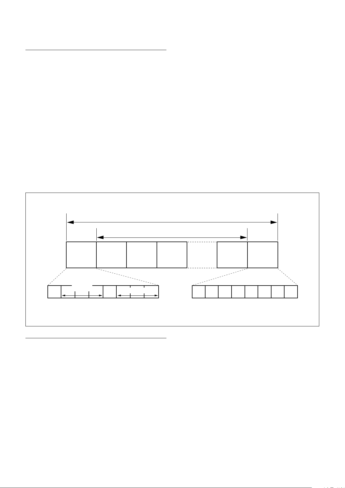
Specifications
VISCA packet structure
The basic unit of VISCA communication is called a
packet. The first byte of the packet is called the header
and comprises the sender’s and receiver’s addresses. For
example, the header of the packet sent to the FCB
camera assigned address 1 from the controller (address
0) is hexadecimal 81h. The packet sent to the camera
assigned address 2 is 82h. In the command list, as the
header is 8X, input the address of the camera at X. The
header of the reply packet from the camera assigned
address 1 is 90h. The packet from the camera assigned
address 2 is A0h.
Some of the commands for setting cameras can be sent
to all devices at one time (broadcast). In the case of
broadcast, the header should be hexadecimal 88h.
When the terminator is FFh, it signifies the end of the
packet.
Header
Sender’s
address
Byte 1 Byte 2 Byte 3
Receiver’s address
Message (1 to 14 bytes)
Command and inquiry
Command
Sends operational commands to the FCB camera.
Inquiry
Used for inquiring about the current state of the FCB
camera.
Packet (3 to 16 bytes)
Terminator
Command Packet Note
Inquiry 8X QQ RR ... FF QQ
RR
1)
QQ = 01 (Command), 09 (Inquiry)
2)
RR = 00 (Interface), 04 (camera 1), 06 (Pan/Tilt), 07 (camera 2)
X = 1 to 7: FCB camera address
1)
= Command/Inquiry,
2)
= category code
30
 Loading...