

Page 1

1
Network High Speed PTZ
Operation Manual
Prior to operation, please carefully read this manual!
Page 2
2
Safety attentions:
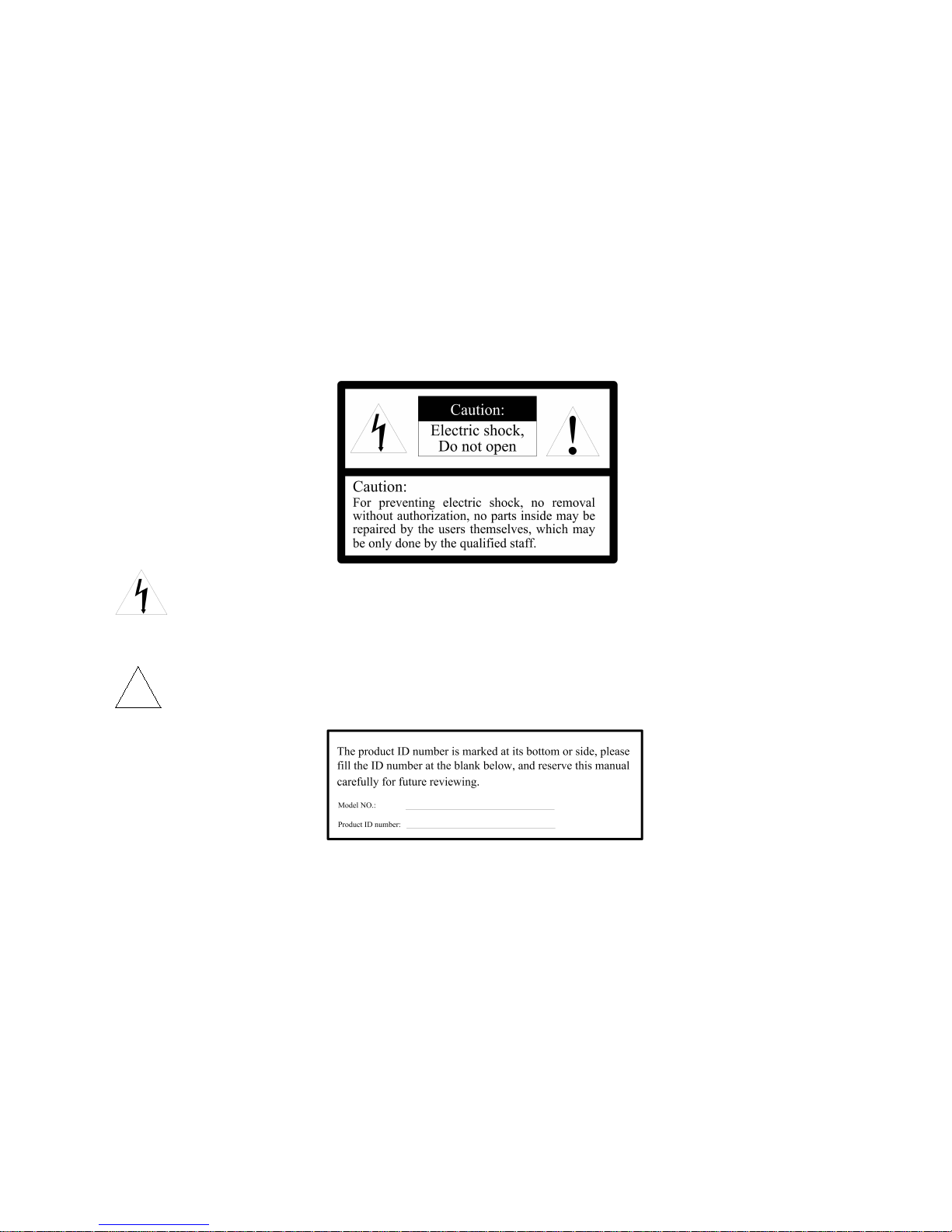
A flash of light in equilateral triangle is used for reminding user that “there are non-insulated dangerous voltage points nearby
this product”, endanger the personnel safety.
An exclamation mark in equilateral triangle is used for reminding user of referring to the literal description about its
operation and maintenance.
V2.0
在正三角形中的注意号,用以提醒用户参考有关
该机的重要操作与维护的文字说明。
!
Page 3

3
Attention
Electrical safety
The installation and use of this product must strictly comply with national and local electrical standards. It has self-provided power supply. Power is supplied
to the product is: DC12V 5A (refer to product identification or connecting line identification). When you use, must be comply with all kinds of electric safety
standard,use products self dedicated power adapter..RS-485 and video signal need has enough distance with high-tension apparatus device & power cable
during transfer, in necessity still need make good safeguard procedures of lightning protection / anti-surge
Transport safety
During transport, storage and installation, damage of the product caused by heavy load, violent vibration and soaking shall be prevented. This product is
transported in form of integral packaging. Any damage of the product caused by transport not in the packaging form adopted during delivery will not be under
the coverage of warranty whether it is shipped by the supplier or returned to the factory for repair.
Installing safety
During installation, please refer to the user installation manual, handle the PTZ with care and do not squeeze any structural component lest mechanical
failure might be caused. The camera glass is a high-grade optical product and may not be touched with a naked hand as it may scratch the glass, impairing
image quality.
Qualification of maintenance workers
All installation and maintenance work about this device shall be completed by qualified maintenance technicians or system installation personnel. In case of
a failure, please find the reason in reference to the manual before repair. If the reason cannot be found, please ask professionals for repair. All related
maintenance work must be done by the maintenance personnel authorized by us.
No removal of camera without authorization
Do not remove the screws or protective cover of the PTZ. There are no parts repairable by users in the PTZ. The repair shall be done by qualified
maintenance personnel.
Page 4

4
Environmental requirements
Temperature: -35℃~+55℃ Humidity: 90% Air pressure: 86-106kpa
Installation request
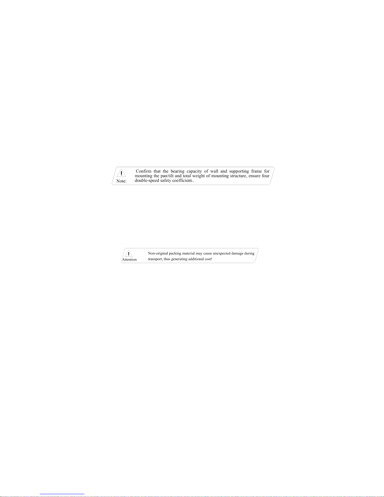
Install the device at a location with sufficient bearing capacity.
Do no store, install or use the product in an inflammable, explosive and dangerous area.
Do not install the product beyond the specified temperature, humidity or power specification.
Do no remove any internal component of the PTZ lest it might affect the use. There are no parts repairable by users inside it.
Whether the PTZ is powered on or not, please do not aim the camera at the sun or a very bright object and do not aim it at or have it monitor a bright
and still object in a long time.
Page 5

5
CONTENT
Chapter I Functions and features.........................................................................................................................................................................................................................7
1.1 PTZ Main features................................................................................................................................................................................................................................... 7
1.2 PTZ Specifications................................................................................................................................................................................................................................... 7
Chapter II Network menu Setting......................................................................................................................................................................................................................... 9
2.1 ONVIF Discovery Tool
configuration camera IP address................................................................................................................................................................. 9
2.2 Log in the network..................................................................................................................................................................................................................................10
2.3 Video Activex install............................................................................................................................................................................................................................... 11
2.4 Video preview......................................................................................................................................................................................................................................... 14
2.4.1 PTZ control.................................................................................................................................................................................................................................. 1 6
2.4.2 Camera parameters................................................................................................................................................................................................................... 17
2.4.3 Advanced setup.......................................................................................................................................................................................................................... 18
2.4.4 Image setup................................................................................................................................................................................................................................. 19
2.5 Device parameters.................................................................................................................................................................................................................................20
2.5.1 Network parameters...................................................................................................................................................................................................................20
2.5.2 Protocol setup............................................................................................................................................................................................................................. 20
2.5.3 Stream setup............................................................................................................................................................................................................................... 22
2.5.4 Record setting............................................................................................................................................................................................................................. 23
2.5.5 Video setup..................................................................................................................................................................................................................................24
2.5.6 Alarm setup..................................................................................................................................................................................................................................2 5
2.5.7 Schedule setup........................................................................................................................................................................................................................... 25
2.5.8 Other setup.................................................................................................................................................................................................................................. 25
2.5.9 Interface setup.............................................................................................................................................................................................................................26
2.5.10 System setup.............................................................................................................................................................................................................................29
2.6 File management................................................................................................................................................................................................................................... 30
2.7 System information................................................................................................................................................................................................................................ 31
Chapter III OSD menu setup...............................................................................................................................................................................................................................32
3.1 Main menu...............................................................................................................................................................................................................................................32
3.2 System information................................................................................................................................................................................................................................ 32
3.3 Camera setup......................................................................................................................................................................................................................................... 33
3.4 PTZ Setup............................................................................................................................................................................................................................................... 34
3.5 System setup.......................................................................................................................................................................................................................................... 40
Chapter IV PTZ Installation Description............................................................................................................................................................................................................43
4.1 Safety measures.................................................................................................................................................................................................................................... 43
4.1.1 Qualification of installation or maintenance workers............................................................................................................................................................ 43
Page 6

6
4.1.2 Requirements for lifting equipment........................................................................................................................................................................................... 43
4.2 Warning................................................................................................................................................................................................................................................... 43
4.3 Ambient requirements...........................................................................................................................................................................................................................43
4.4 Cabling safety.........................................................................................................................................................................................................................................44
4.5 Installation preparation......................................................................................................................................................................................................................... 44
4.5.1 Basic requirements.....................................................................................................................................................................................................................44
4.5.2 Check the space for installing and strength of structures....................................................................................................................................................44
4.5.3 Check the structural strength....................................................................................................................................................................................................45
4.5.4 PTZ power-on self-test.............................................................................................................................................................................................................. 45
4.5.5 Please keep all packing materials of the PTZ....................................................................................................................................................................... 45
4.6 Installation methods...............................................................................................................................................................................................................................45
4.6.1 Shock adsorb install ( For optional).........................................................................................................................................................................................45
4.6.2 Vehicle-mounted type install (Directly install on the top of Car) for optional....................................................................................................................46
4.6.3 Wall bracket (For option)........................................................................................................................................................................................................... 46
4.7 Outgoing lines of PTZ............................................................................................................................................................................................................................48
Annex I: Troubleshooting.............................................................................................................................................................................................................................49
Annex II: Lightning and surge protection..................................................................................................................................................................................................50
Annex III: Maintenance of the terms of service....................................................................................................................................................................................... 51
Page 7

7
Chapter I Functions and features
1.1 PTZ Main features
IR night vision function, realize D/N monitoring, IR LED control & AIO ICR filter disc synchronous switch, to achieve perfect night vision effect
Max.Resolution up to 1080P(1920(H)×1080(V)/30fps)
New type of ultra-thin precision stepper motor drive, stable running, accurate positioning
Coding standard: H.264 High Profile compress ability
Progressive scanning CMOS, catch running image no sawtooth
Humanized focus speed , auto matching technique, long focus self-motion limit speed
Max. Support 255 preset,Power-interruption data memory
8 groups cruise, each group contain MAX.32 preset,each preset stop time and cruise speed can adjust respectively
8 self-learning tracks,each group can storage 1024 pcs PTZ action.
Support auto iris and auto electronic shutter and adapt to various surveillance environments
Recording function: Support Manual,alarm,timing recording,support recording in advance, reserved space, auto delete function
Built-in WEB server, support through WEB to proceed real-time video, equipment management and control,video playback
Intelligent auto demist function, so it will let products always has HD image at any time
1.2 PTZ Specifications
Power supply
Input
DC12V / 5A
Video
TVI
BNC interface,TVI signal output
Network
H.264 coding,Frame rate 1-25 for option
Protocol
ONVIF
ONVIF protocol
Page 8

8
GB/T28181
Chinese standard
TCL
Third part protocol
VSIP
Third part protocol
FTP
Screen shot upload FTP server
NTP
NTP Server time tick
PTZ
PAN
Speed: 120°/S,360° rotation endless
Tilt
Speed: 30°/S,Run range: -15°--+90°
Preset
255pcs
Cruise
8 groups
Self-learning
8 groups
Home
Support
Privacy mask
8pcs (It is according to the camera module)
Focus limiting
Support
IR
Max.IR distance is 80M
Surface
IP grade
IP66
Humidity
10%-90%
Page 9
9
Chapter II Network menu Setting
2.1 ONVIF Discovery Tool
configuration camera IP address
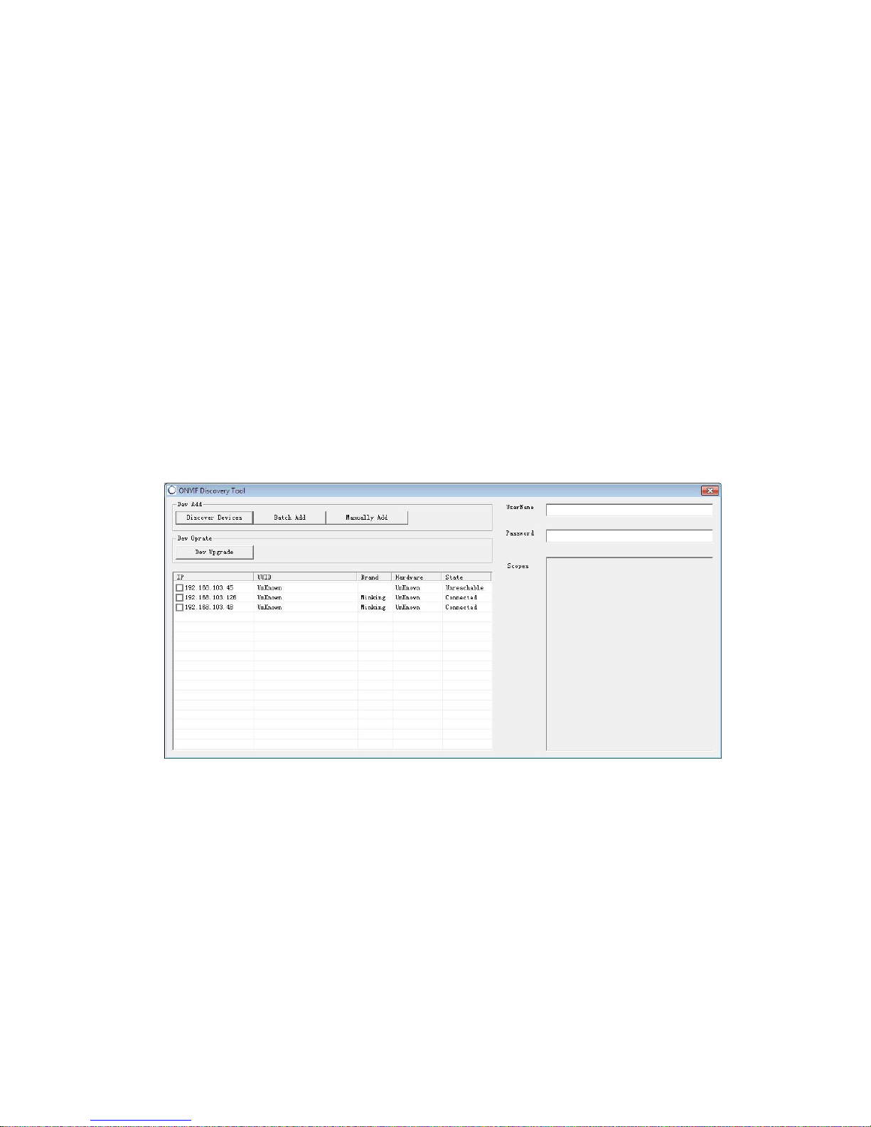
In system CD,we support ONVIF Discovery Tool for user, it can used for device management test:
Search IP camera or Video server device which in the network
View IP,Hardware...etc information
Modify IP, subnet mask and gateway
Run ONVIF Discovery Tool management tool,auto searching available IP camera in current network. List IP address,UUID、Hardware..etc.information.
Page 10
10
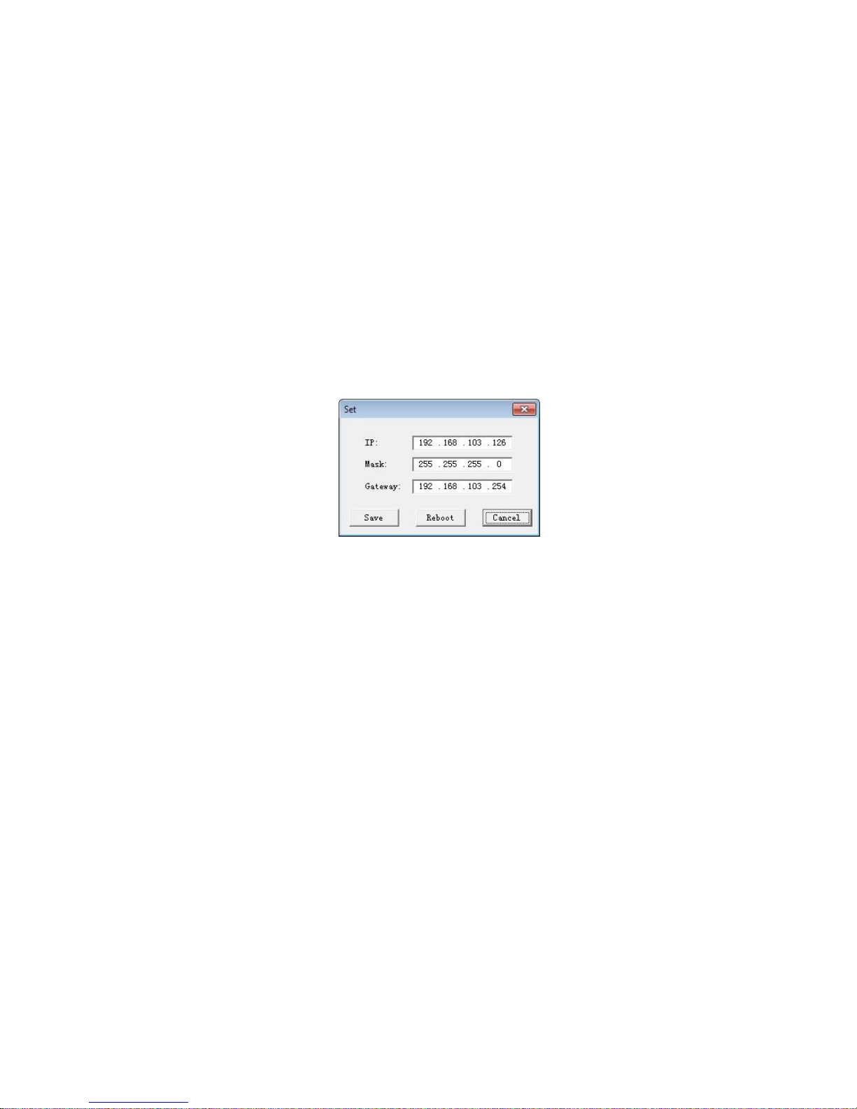
Due to each camera from factory, all the ID address are the same,so if before install Ip camera, you can use ONVIF Discovery Tool to configuration IP
address. Use mouse to choose the device,input the device ONVIF protocol’s user name and password, double-click will pop-up current device’s
information dialog box, can configurable IP address..etc.After modify, click”SAVE”, it will show you a tip to tell you are succeed, then click”Reboot” to
re-start the device.
Test whether connected
After setup IP address, click left bottom of PC: Start--all program--attachment”,open”Command Prompt”,use PING command to test whether PC has
connected with IP camera.
Command as: Ping 192.16 8.1 .8
If screen show“Request timed out.”or” destination host unreachable”,it means install not OK.Please check below:
Hardware connect correct or not
PC’s TCP/IP set Full-Mesh as IP camera or not.
Whether network forbid PING command or not,please ask network manager.
2.2 Log in the network
Page 11
11
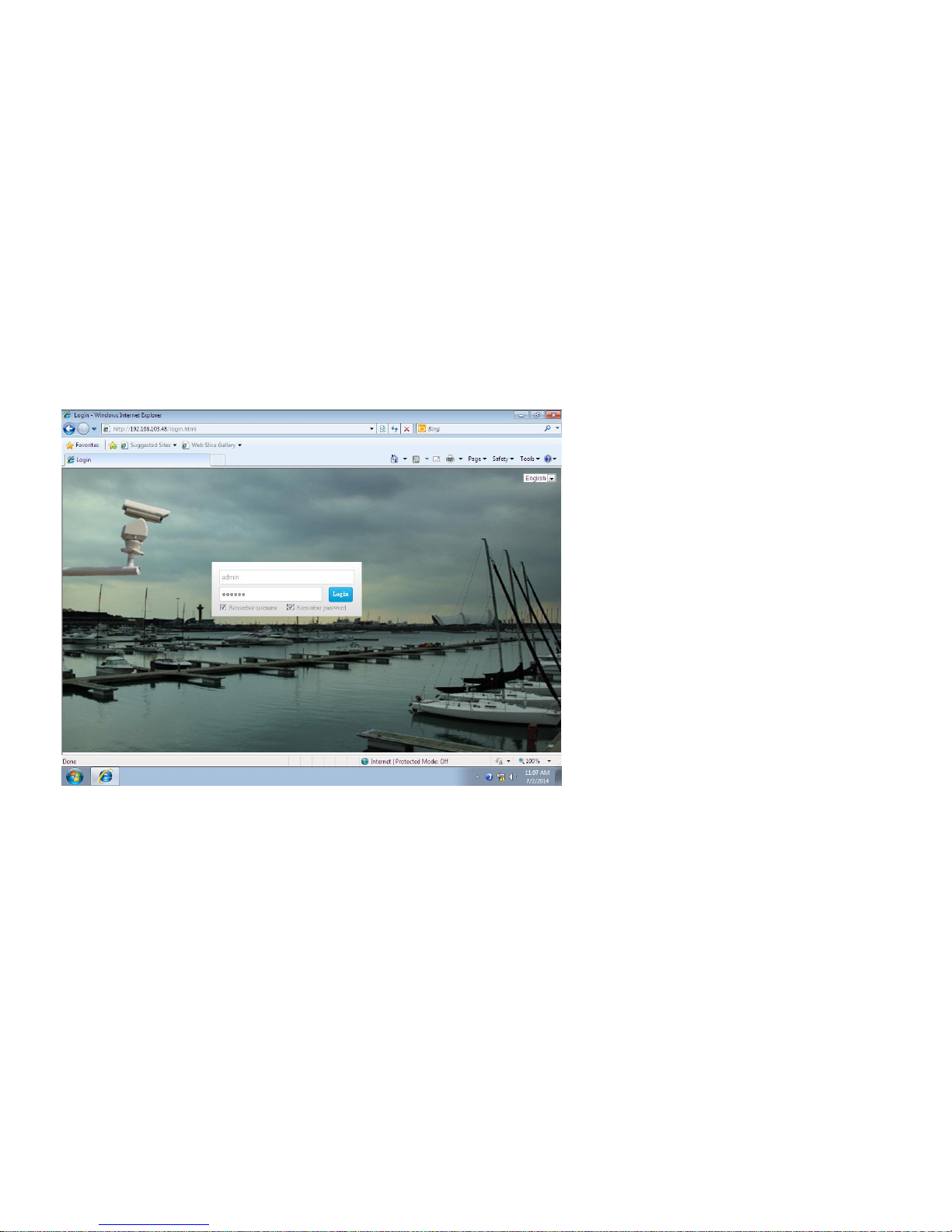
This chapter introduce how to access IP camera through web browser. This manual’s interface are under Windows XP and IE8.
When through IE browser to preview IP camera’s image,
need install VLC.EXE software firstly, after install, open IE,
input IP address (Default: 192.168.1.8),Enter into log in
interface. In log in interface,input IP camera’s user
name(Default: Admin),Password(Default: 888888) ,you can
choose remember user name and PW,then click” log
in”,when going into user interface, will pop-up below dialog
box, click”OK” , after a series install operate, and install
video Activex, re-start browser, you can view video.
2.3 Video Activex install
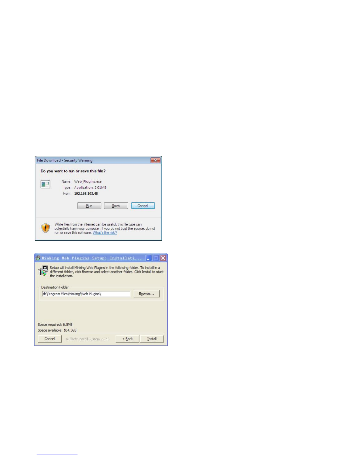
Log into user interface, you can click top right”Player download”Interface will pop-up player download dialog box,shown as below Picture,choose”Run”, will
Page 12
12
pop-up below dialog box:
Choose install deposit disk, click [Install], continue to install
Page 13
13
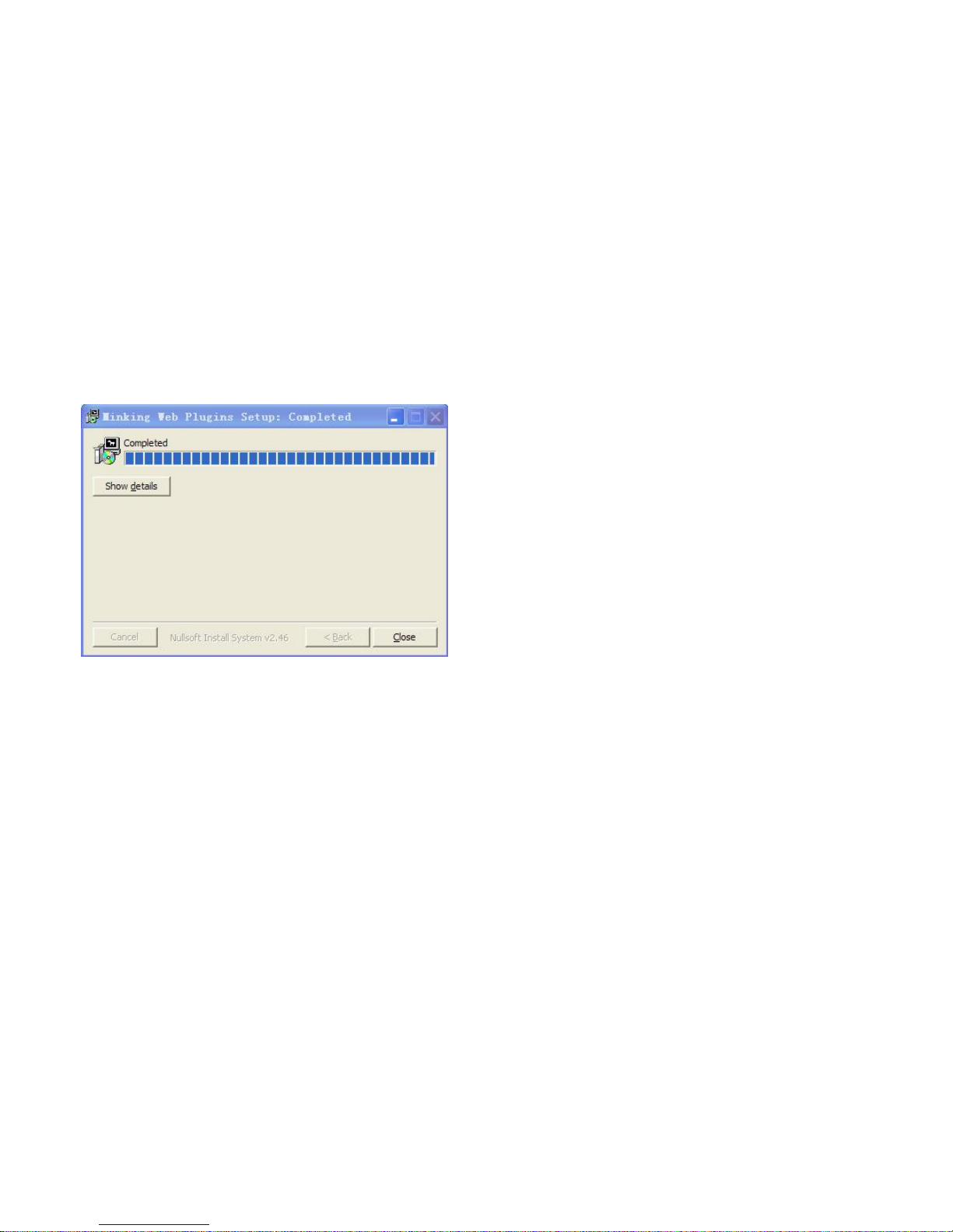
After install,as left picture,Click”Close”,finish install, close IE. Then Log-in PTZ IP
address, can view video.
Ps: If your Activex in your PC is old version,IE will pop-up information, to ask you
install newest Activex version.
Page 14
14
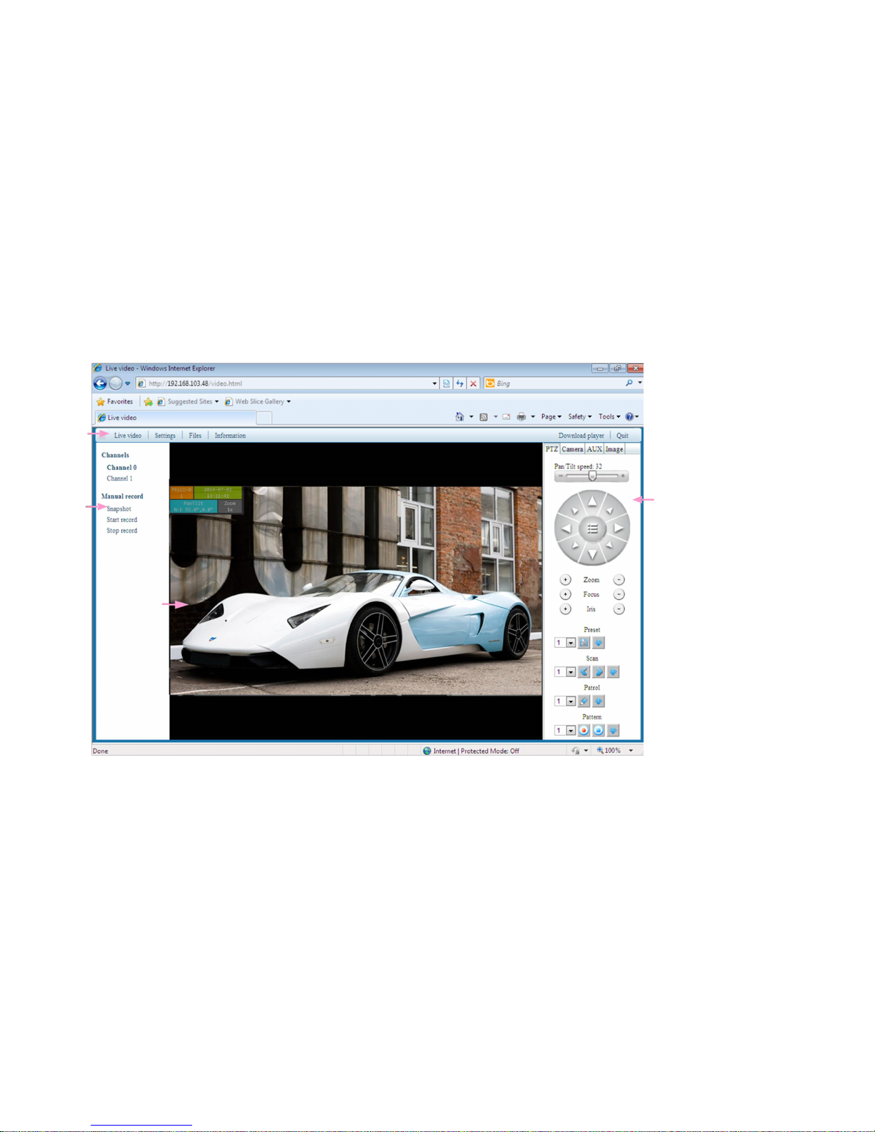
2.4 Video preview
Note:It always has delay if transmission by IP, it depends on user’s PC CPU and qualities of switcher and router.Normally, MP IP
1
2
4
3
Page 15
15
video has <500ms delay.
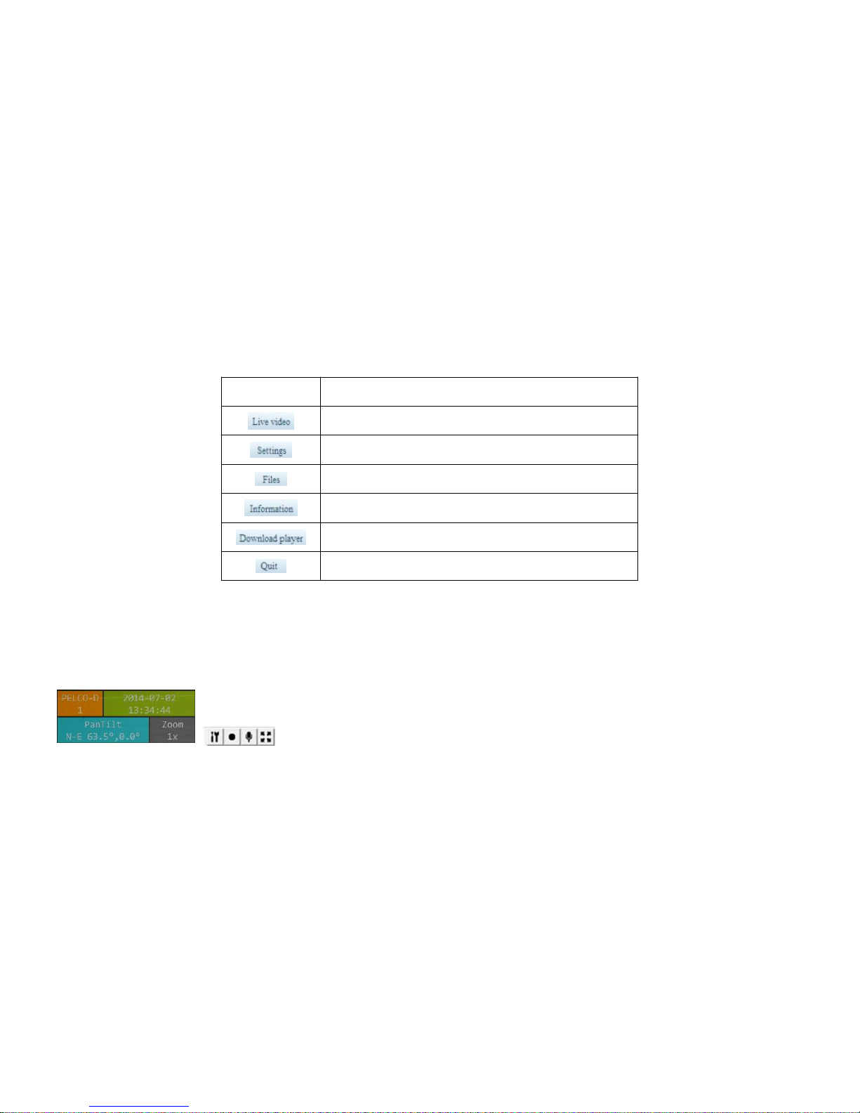
Area 1: Toolbar: Click into corresponding function
ICON
Explain
Enter the image code stream, PTZ, camera control interface
Into network parameters and speed dome function Settings
Enter the picture management or local video playback and
download
System information display
Player Activex download
Exit user interface, back to Log-in interface
Area 2: Device can do screens hot & local record at the same time, in the video browsing area, use right mouse to click, choose [ option], to do local record
video save path & sliced time setting up. Screen shot file auto save to TF card
Area 3: Preview interface:
Top left OSD show PTZ’s protocol,ID,Year,date,time,PTZ direction and specific coordinates,camera’s zoom,PTZ current
movement.
distinguish between setting local video save path, local video, audio output, full screen
Page 16
16
Area 4: PTZ control, camera specification,Peripherals management function.
2.4.1 PTZ control
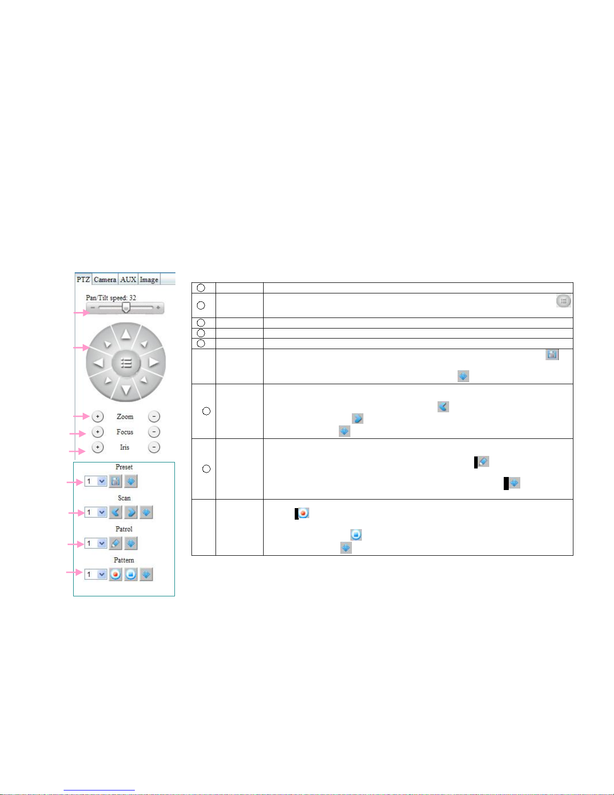
After open preview image, each key in the right of interface means:
1
Speed key
Setup PTZ rotation speed.
2
Direction
key
Control PTZ”up,top left,top right,down,left bottom,right bottom,right,left. Click
icon,can call OSD menu
3
Zoom
Change lens zoom(invalid for auto Zoom camera)
4
Focal
Change lens’ focus (invalid for auto focus camera)
5
IRIS
Change Lens’s IRIS (invalid for auto IRIS camera)
⑥
Preset
1. In preset box choose preset No. Trough[2nd key]to adjust camera position,click“ ”
will save current preview point. If need customize other reset,please re-done Step 1.
2.Call back preset:In preset box choose preset No.Click“ ” can access seted preset
7
Scan
Scan means PTZ constant speed in a clockwise from left limit point to the right limit
point,setup step as below:
1. Through adjust camera to desired point,click “ ” can set left limit point. Pan move
PTZ to 2ndposition, click“ ” can set right limit point&scan speed
2. After operate,click“ ” can call back scanning line.
8
Patrol
Patrol is a path for camera, through multiple serial number cruise points,patrol setup as
below:
1. Setup patrol point 1,in display box, choose patrol No.click“ ”,go into patrol point edit
contain: title,preset,stop time,and patrol speed.
Re-operate 1ststep,to setup other patrol point. After operate, click“ ” can callback
patrol line.
⑨
Pattern
Pattern used to record camera running line.Pattern setup as below:
1. Click“ ”,start into pattern setup
2. Operate PTZ kinds of control。
3. After operate, re-click“ ” can finish setup.
Search pattern: Click“ ” start run pattern.
1
2
3
4
5
6
7
8
9
Page 17
17
2.4.2 Camera parameters
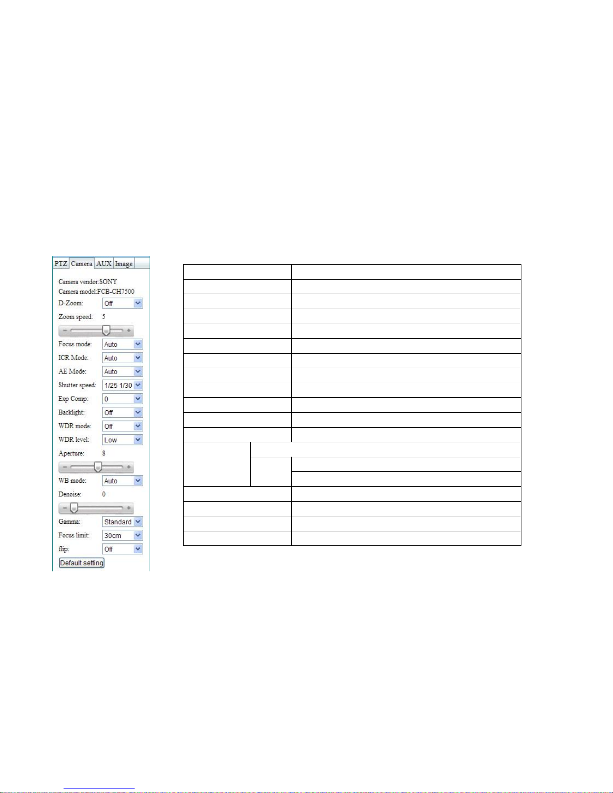
After open device preview, choose right side “Camera”, specification as below:(Different camera module, specification will different)
Camera brand
Display camera brand
Camera model
Display camera model
D-zoom
ON/OFF
Zoom speed
0-7
Focus mode
Auto/Manual
ICR Mode
Day/Night/Auto
AE Mode
Auto/Manual/SP/AV
Shutter speed
1-1/10000
Exp Comp
-7-7
Back light
ONOFF
WDR mode
ON/OFF
Aperture
0-15 (Aperture priority effectively)
WB mode
Auto/Indoor/Outdoor/Auto tracking
Manual
RGC 0-255
BGC 0-255
Denoise
0-5
Gamma
Standard/Direct line/low/middle/high
Flip
ON/OFF
Default setting
Camera parameter is set back to factory Settings
Page 18
18
2.4.3 Advanced setup
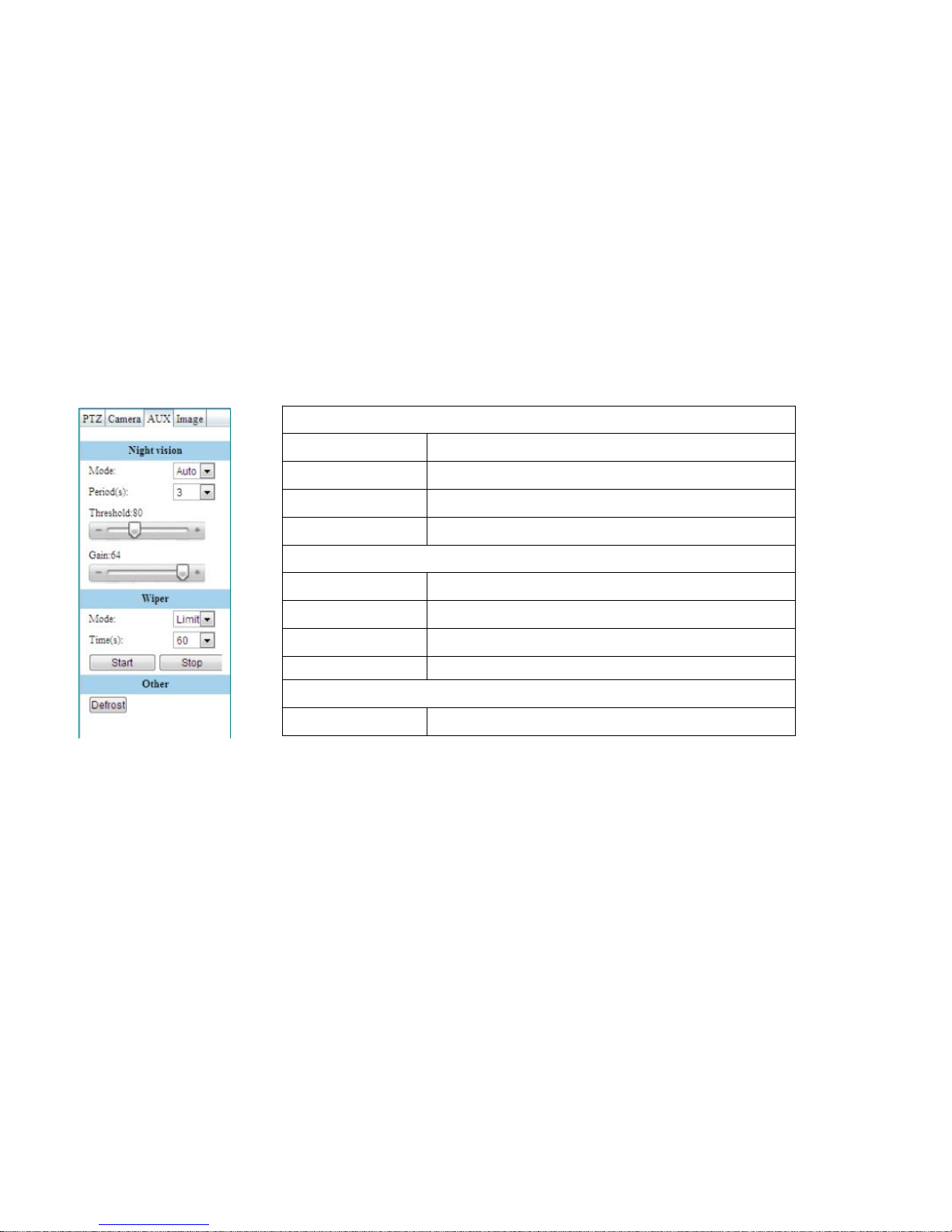
After open device preview, choose”AUX”, parameters is as below:
Night vision
Mode
OFF/ON/AUTO
Period
0-60
Threshold
0-255
Gain
0-64
Wiper
Mode
One /limit/N time
Time
10-600
Start
Start wiper
Stop
Stop wiper
Other
Defrost
User heater to defrost
Page 19
19
2.4.4 Image setup
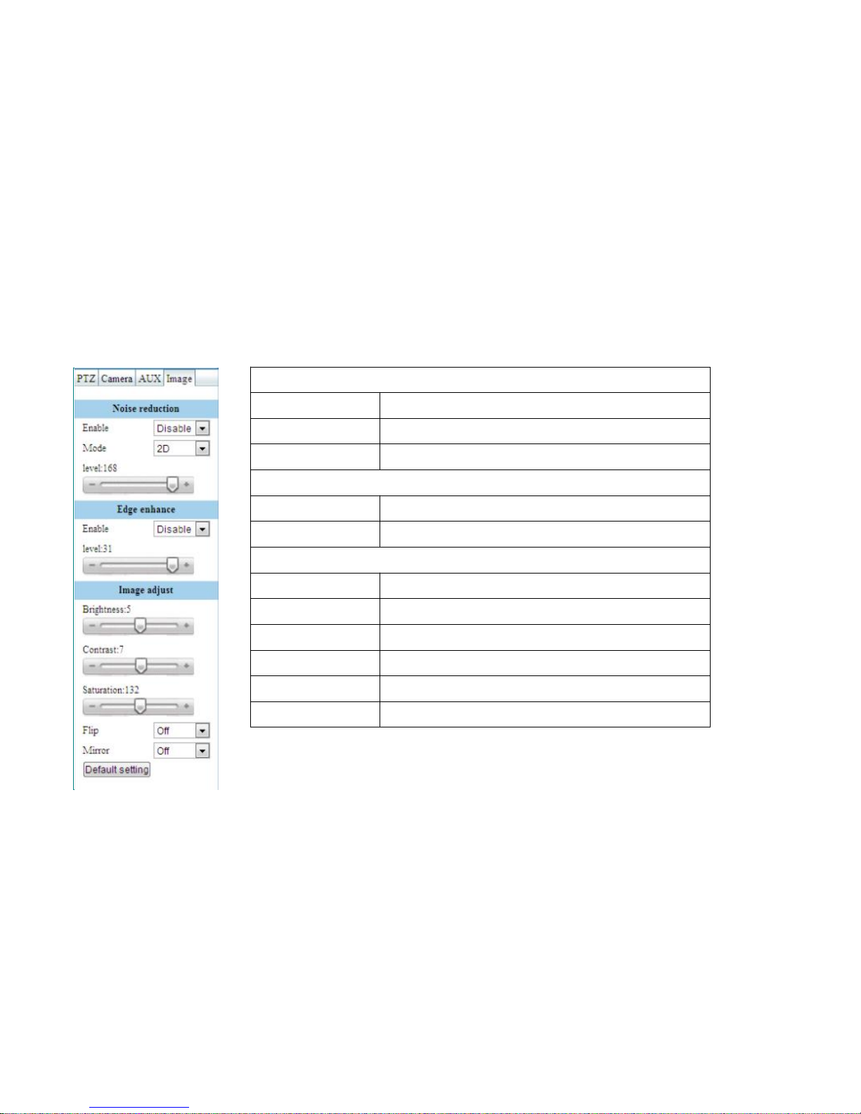
After open device preview, choose”Image”,parameters is as below:
Noise reduction
Enable
Disable/ON/Auto
Mode
2D/3D/3D+/Strong noise reduction/Mixed noise reduction
Level
0-168
Edge enhance
Enable
Disable/ON
Level
0-31
Image adjust
Brightness
0-127
Contrast
0-127
Saturation
0-255
Flip
Image up and down prevision
Mirror
Image left and right prevision
Default setting
All setup in “Image” are going into default setting.(Factory)
Page 20
20
2.5 Device parameters
2.5.1 Network parameters
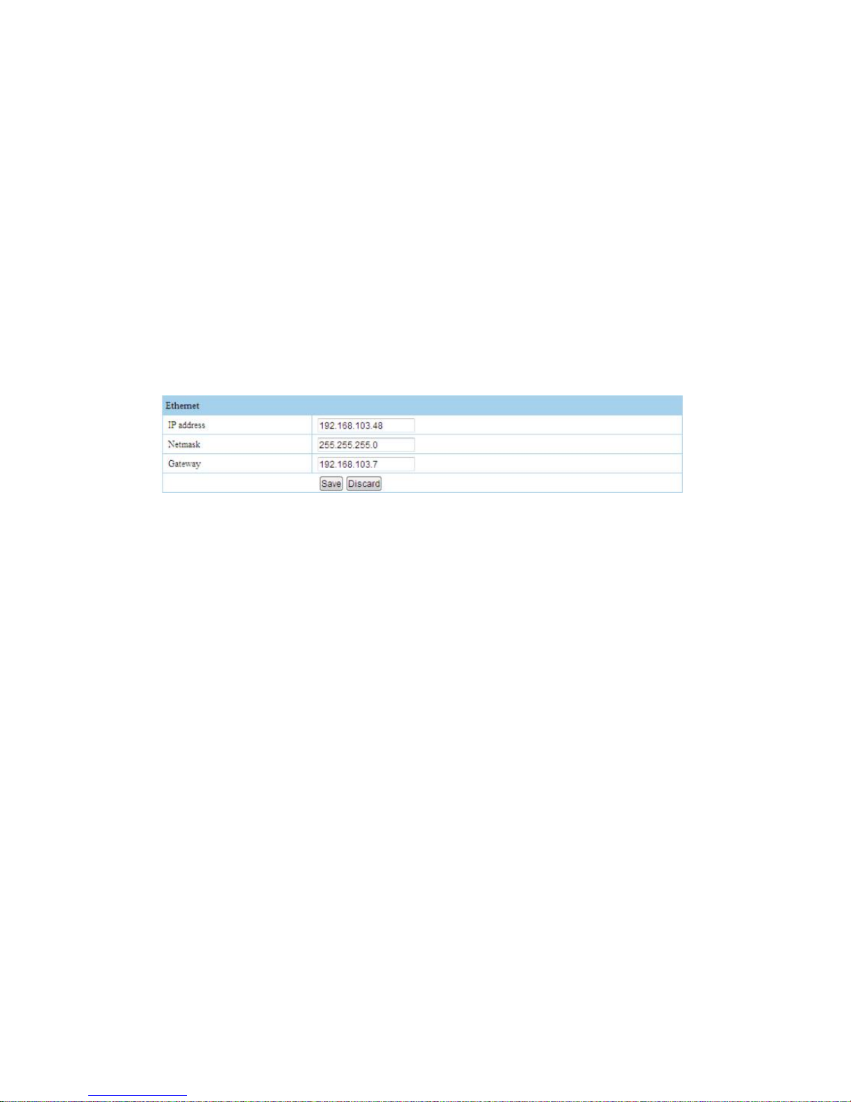
Go into <Device parameters>→<Network parameters>.then you can setup network parameters.
As other IP device, connect and use IP camera, must let IP camera’s IP address Full-Mesh as user PC’s IP address. Please note that: In the same LAN, IP
address can not be the same, it will has clash, and let device can’t work.
After modify IP address, click”SAVE” ,it will display”Now modify the network address, the page will automatically jump in 5 seconds!If there is no successful
jump please manually modify.”
IP camera is a kind of IP device, before use, need rational allocation IP address,gateway..etc.information. We had already configuration default IP
information, this value can be change if you need.
The device IP address192 .1 68.1.8
Netmask:255.255. 225 .0
Gateway:192.16 8.1 .1
Data port:600 2
2.5.2 Protocol setup
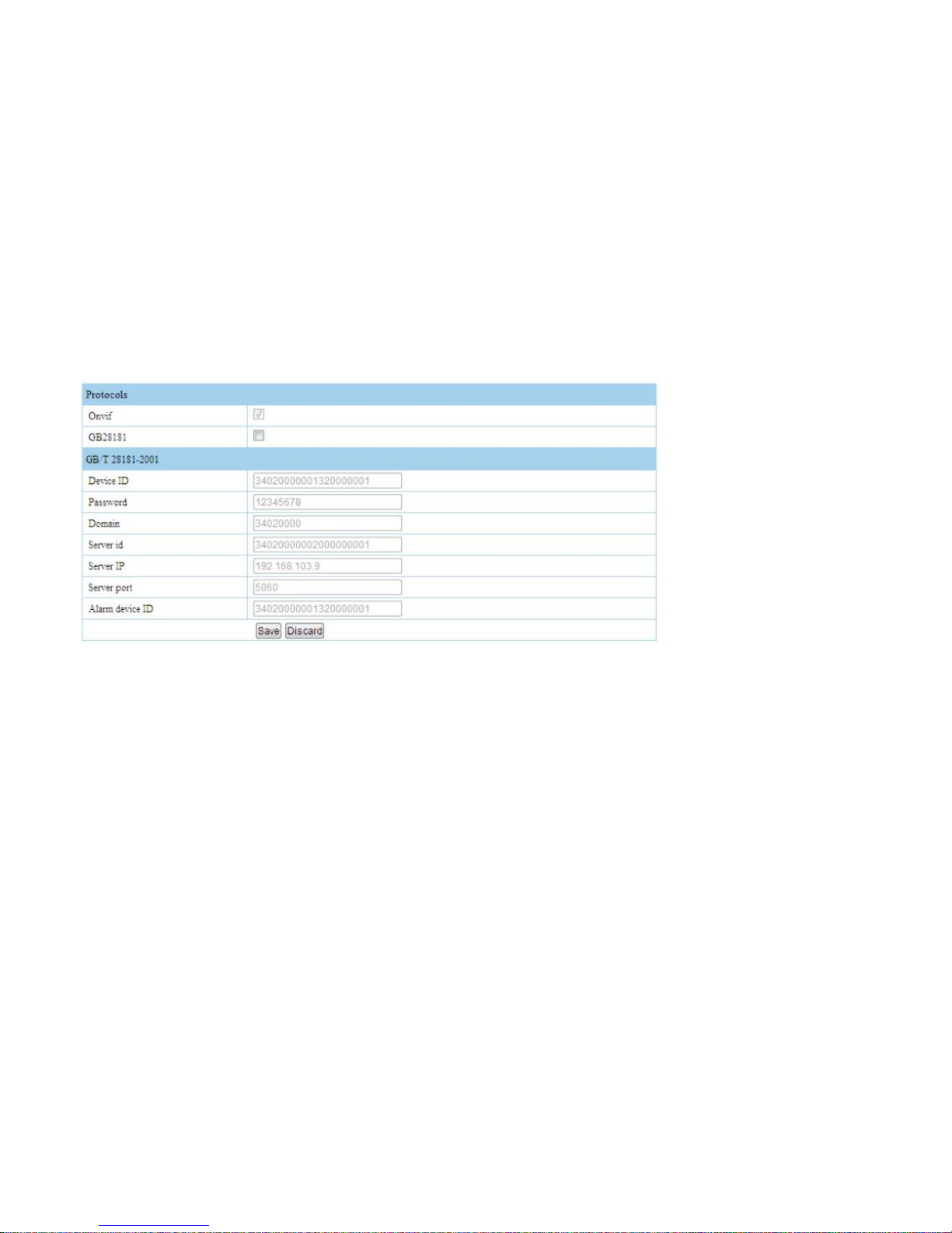
Onvif protocol default open, Device ID is 28181 server assign to the camera’s ID , Registered password is needed for the corresponding device ID
password,device is in 28181 domains,sever ID is 28181’s server ID, server’s IP is 28181’s IP address, sever port is sever provide to outside’s port NO. Alarm
device ID is when the camera catch alarm information, will according to this
ID to send alarm information.
Page 21
21
Note: All the parameters are provide by 28181 device, details please ask28181 server manager.
Page 22
22
2.5.3 Stream setup
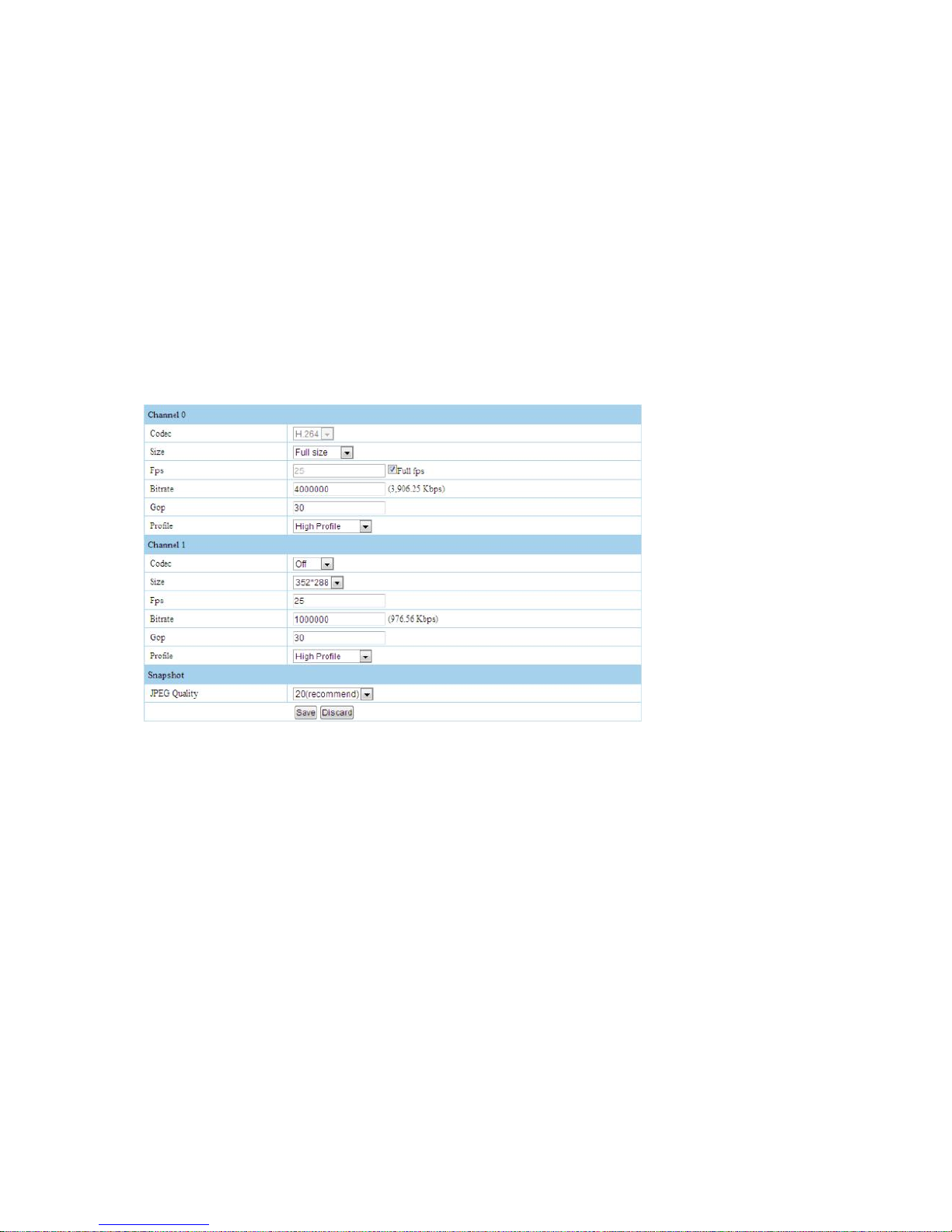
Enter<Device parameters>→<Stream setup>, can setting stream
Stream type: Main stream, sub-stream,both of them are video stream, also can do customize setting for size,frame,rate,Frame interval, level. All these setting
are used for adjust video (or preview) image quality and storage file bit. Main stream are default choose, sub-stream can be choose, but not default choose.
Full frame rate is default output frame rate of camera,MAX.frame rate
Frame interval: also means Key frame, 1 frame interval, will influence with image quality and stream.
Sub-stream’s option open, then”Real video”--”choose stream”---”sub-stream” can be choose.
JPEG quality: Recommended value 20, the lower value, the better image quality
Page 23
23
Auto snapshot
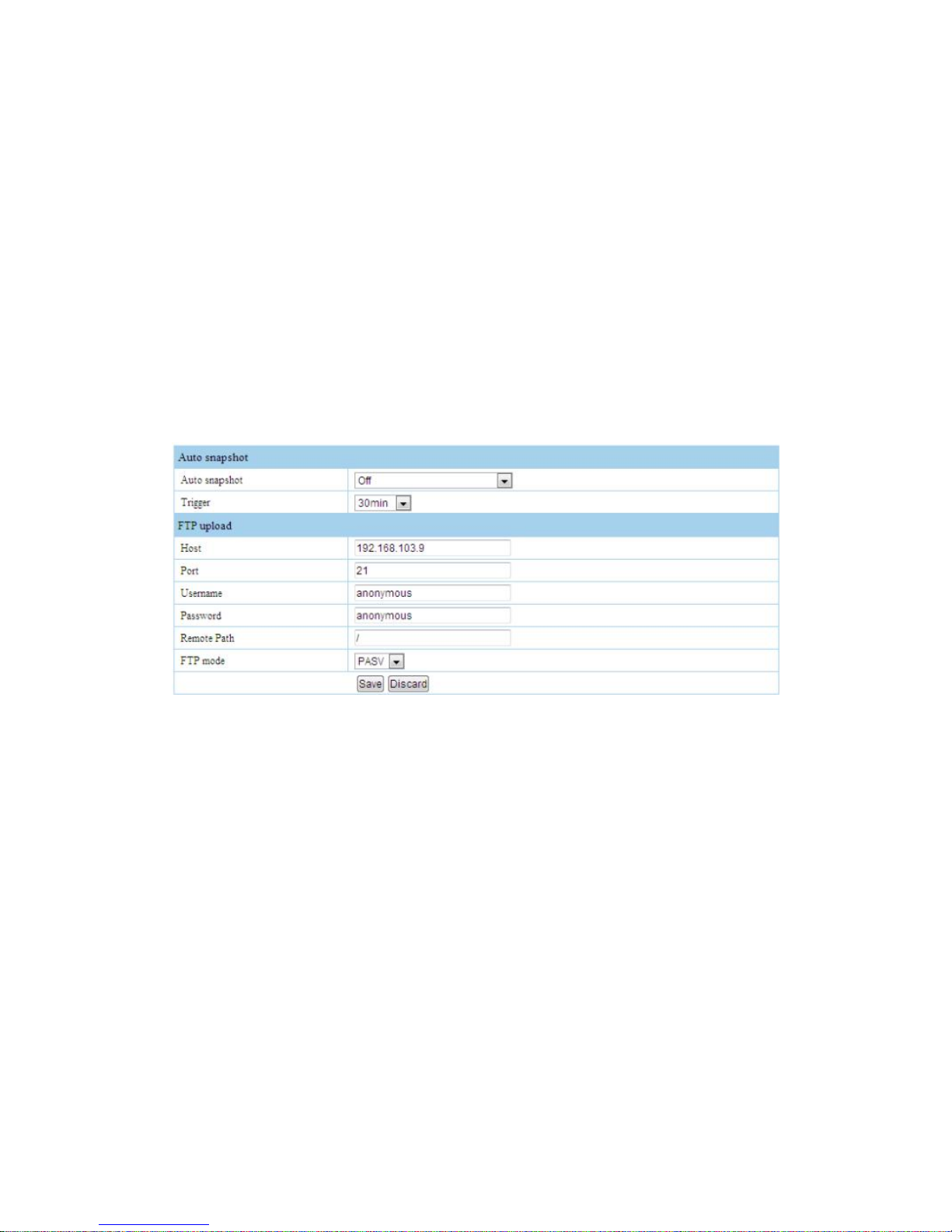
Auto capture can be close, also can transmission to SD card,FTP, also can uploading to SD card & FTP to save. Trigger set time means at regular intervals
will capture a picture by PTZ. FTP uploading, address: FTP server address. PORT: FTP server port, default is 21,user name: FTP user name, PW: FTP pw,
uploading path: FTP uploading path,default is Root directory, FTP mode: FTP server work mode, default is PASV.
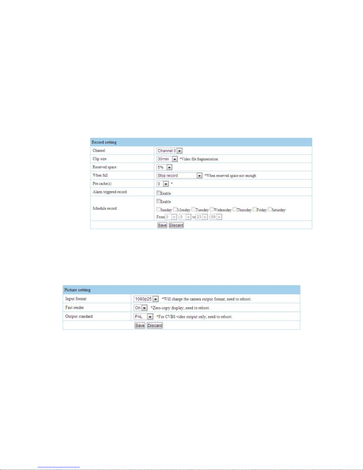
2.5.4 Record setting
After trigger alarm record & timing record, device will auto record, record video file will save in the TF card, when trigger alarm, it will auto record. Timing
record, according to task planning timing record. Record mode can be alarm record and timing record composite mode
Page 24
24
When record time too long, can make video file integral point automatic subdivision,this can convenience to search or playback image file. When TF card’s
free space is lower than setting value, will stop record or automatic to delete oldest record file then record again.
2.5.5 Video setup
Input can set as 1080P25、1080P30、720P50、720P60, change this option will change camera video type,and influence coding and output video. Output
system: Change NH1 series’s CVBS analog system(PAL/NTSC) will not influence TVI series products’s output, modify this parameters need reboot device
Page 25
25
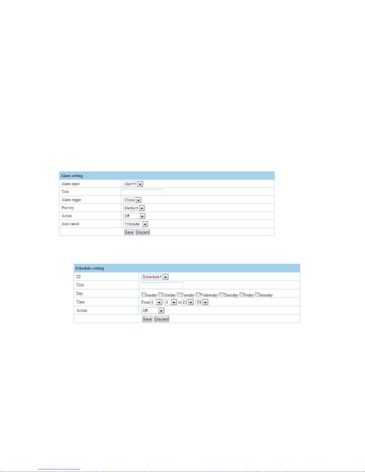
2.5.6 Alarm setup
Alarm input property contain high lever and low lever two kinds, please according to join up alarm device and real using control type to choose suitable
property. Normal close: at ordinary times open circuit, when has alarm signal trigger, it will processing circuit. Normally open: at ordinary times short
circuit,when has alarm signal trigger , it will turn-off circuit. After alarm, can setup corresponding linkage process mode
2.5.7 Schedule setup
Schedule function means automatic run function, let PTZ do corresponding active during the time. 1-8 schedule can be choose. In schedule title can edit
schedule name, date: From Monday to Sunday can be choose, time 00:00-23:59 is a whole day.
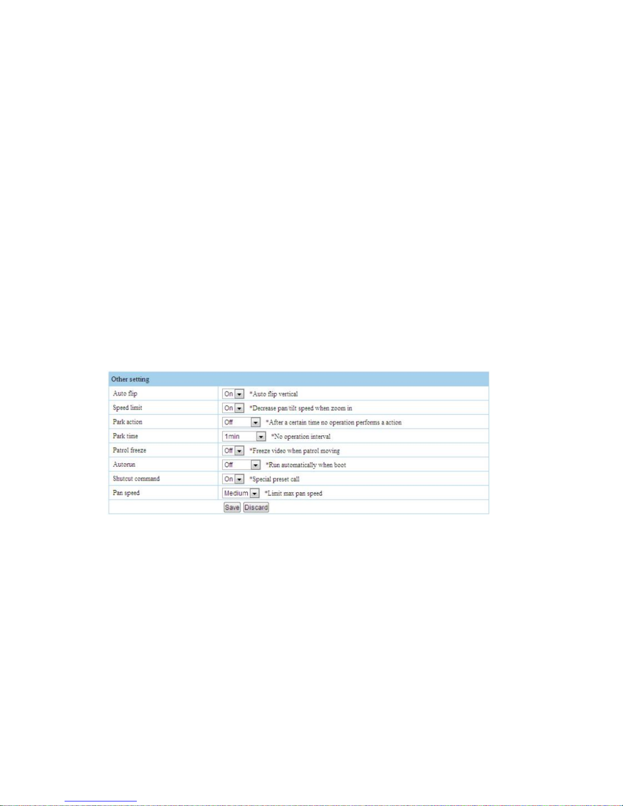
2.5.8 Other setup
Page 26
26
Auto flip: When camera come to the tilt position, pan can auto run 180°, ON/OFF for option.
Speed limit: When camera in high zoo, PTZ or speed dome will automatic let speed slow, ON/OFF for option
Park action: When this option Open, will open park action function. This means when in a while, user do not has any control or active, PTZ or speed
dome will back to the original point. When PTZ or speed dome in a patrol , will not back to original point. If you no need it back to original point, please
let this option OFF.
Park time: Set park action time,means in how many time if PTZ or speed dome do not be controlled, it iwll be back to original point, 1-99mins for option.
Patrol freeze: During patrol, freeze image, ON/OFF for option.
Auto status: After power on come to re-set state, day mode/night mode/ patron 1-4/pattern1-4,preset1-4,scanning 1-4 OFF.
Shortcut command: quickly command ON/OFF
Pan speed: Choose pan speed. Max.fast/fast/middle fast/low fast for option.
2.5.9 Interface setup
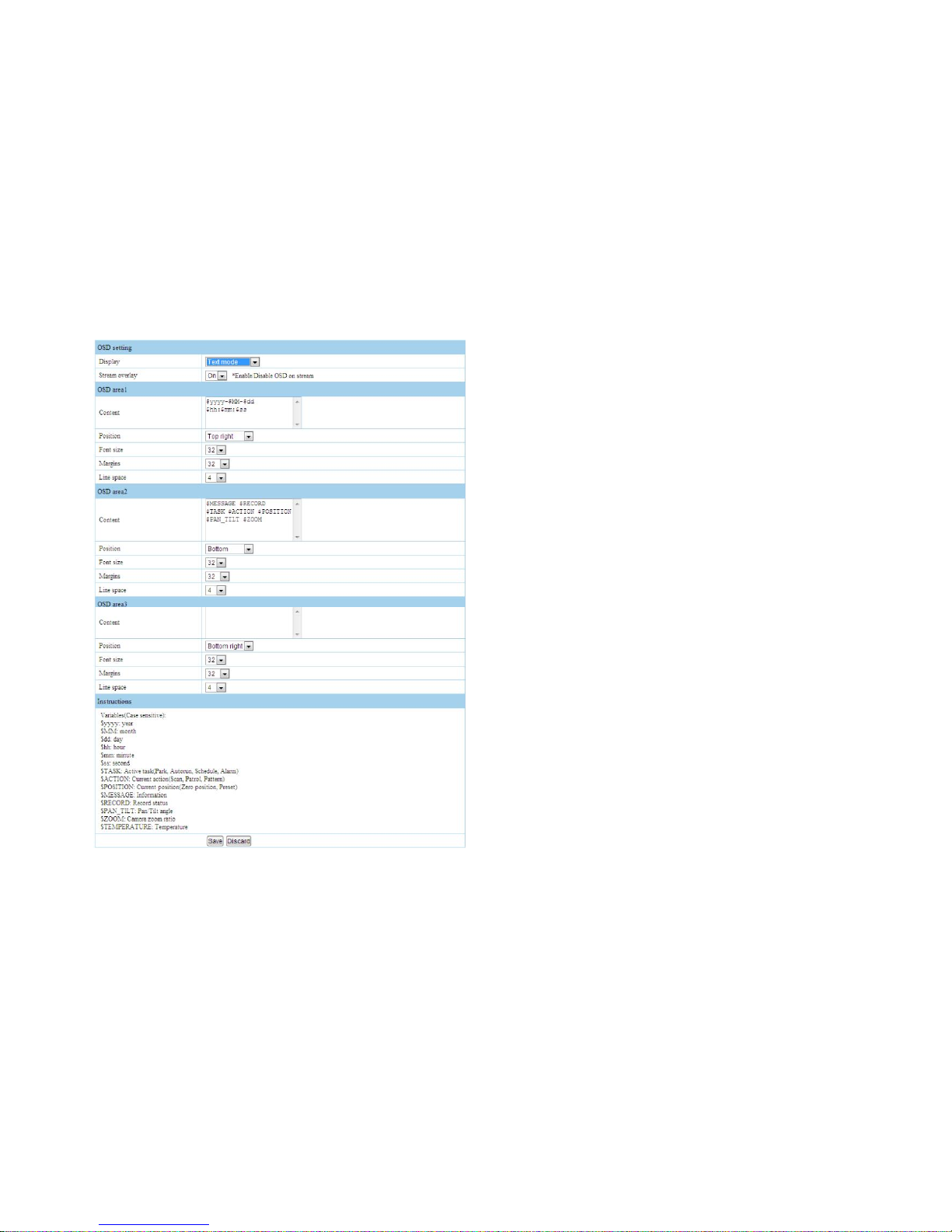
Hide character which on the top left of preview interface(OSD menu can are all hide both in analog image or IP image)/Image mode(Display image mode
Page 27
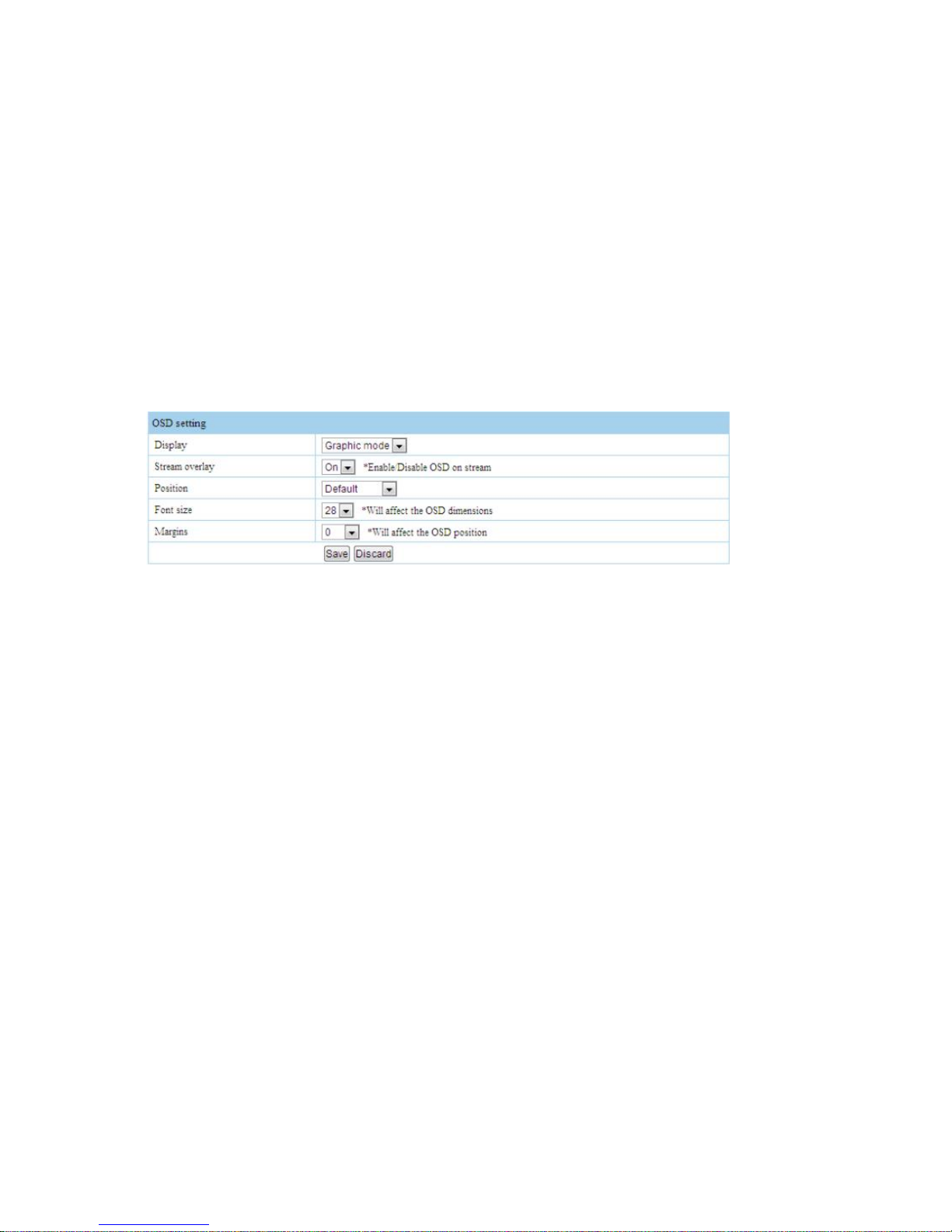
27
OSD menu)/TXT mode(Display TXT mode OSD menu)、subtitle position, typeface’s size, edge distance,code flow superposition, and other thing to edit.
Edge distance means preview interface top left character the distance of video edge.
Page 28
28
When choose TXT mode will display below function menu, superposition
divide to 3 TXT subtitle, TXT content can be custom English or Chinese or any
other character, also can be PTZ or speed dome built-in common
variations,through variations can catch some dynamic information. For
instance: In “connect” common variations,.eg:$mm is mins variations,OSD
display device’s time’s mins. Variations also can be free combination,
subtitle’s position, typeface’s size, edge distance,line spacing can be edit.
Each OSD area MAX size is 480x160. If wide than this,will automatic word
wrap, if high than this , some part will not display.
[Stream overlay]option control character display or hide in IP image. But not
control character in Analog image.
Note: Character in preview interface,if change English or Chinese need in
PTZ or SPEED DOME’s meanu, you can call 64 preset, will display PTZ or
SPEED DOME’s OSD menu, ”Language setup” to modify.
Page 29
29
2.5.10 System setup
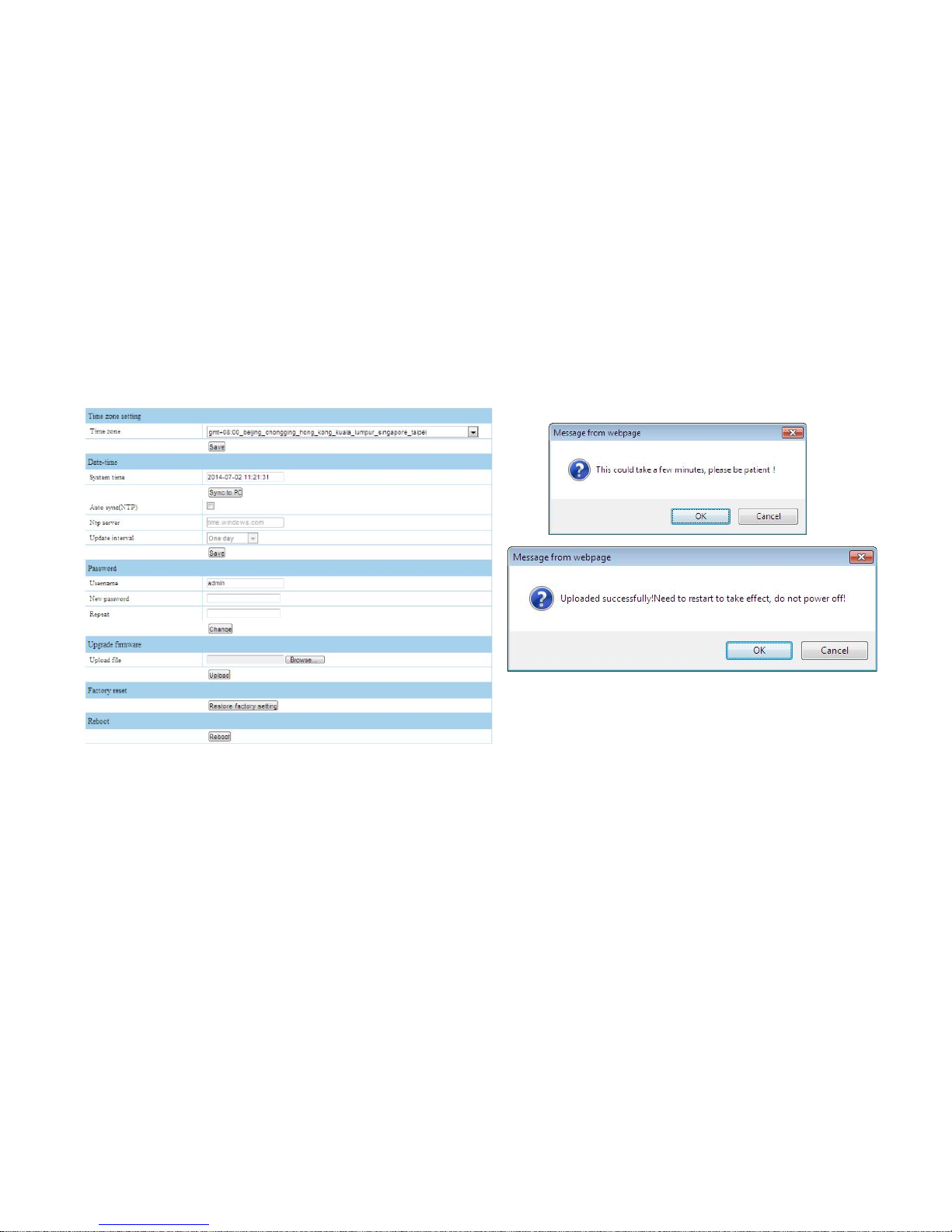
It can setup timezone, local time,PW. Click”Restore factory setting” will change to factory setting. Click”Reboot” ,device will auto re-start.
Before update, please confirm that update routine is copy in PC,
choose”Browse” to add update file, click”upload”,screen will display
above dialog box” This could take a few minutes,please be patient!”
Click”OK”,update time according to how big update file, whole update package need around 1-2mins. After uploading, will display2nd dialog box, tell you”
Uploaded successfully!Need to restart to take effect,do not power off!” Click “OK” will re-start, or choose”Cancel”,then click”OK”,device will update after
re-start, this time re-start time will be long, during re-start do not power off.
Page 30
30
2.6 File management
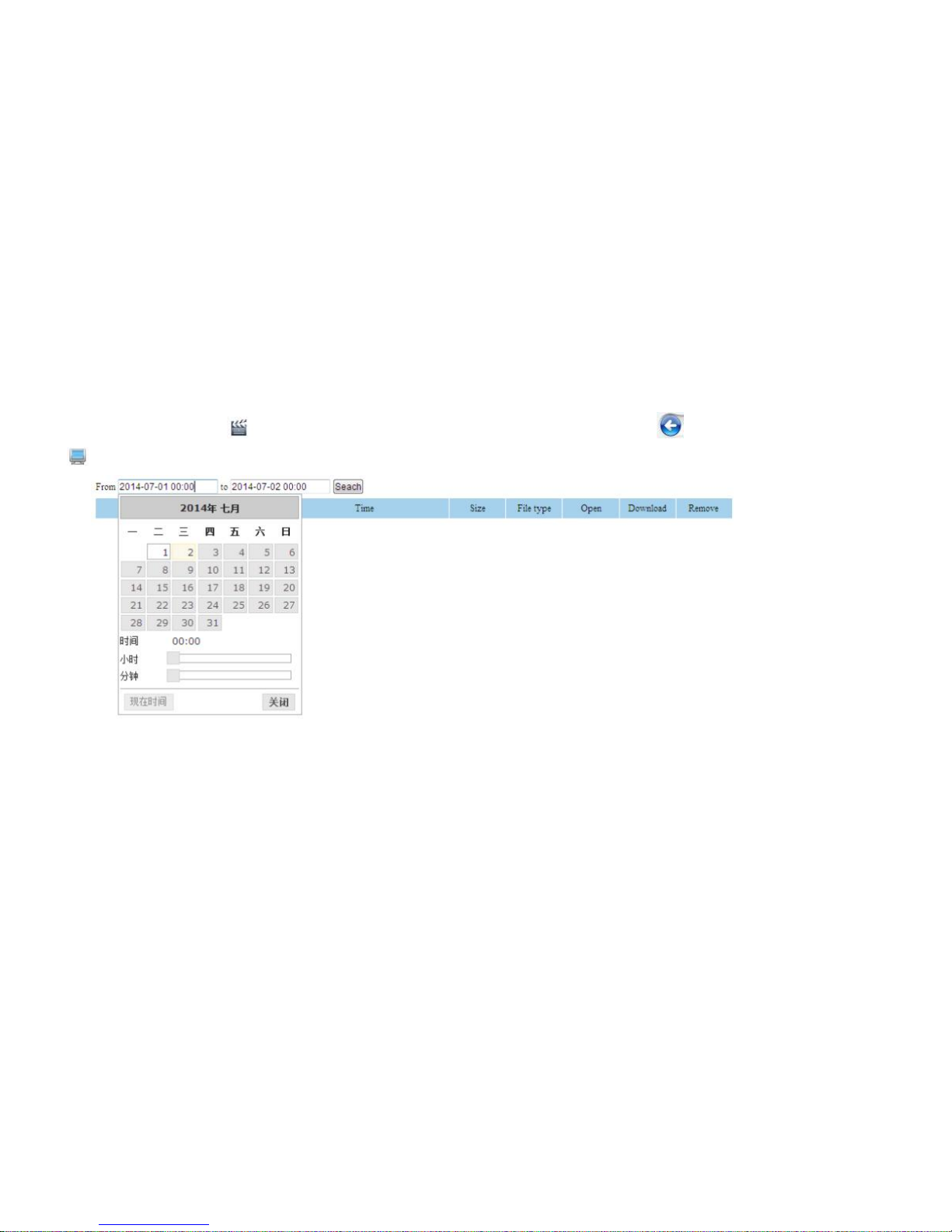
Time quantum not write anything, Click search directly, will display all file which storage in TF.It can display: file name, time, file size, type,support file’s
download and delete function. means this file is video, click this icon will open video file to playback, click will back to file management interface.
means this file is picture, click can view , in the picture click mouse can amplificationcorresponding position.
Page 31
31
2.7System information
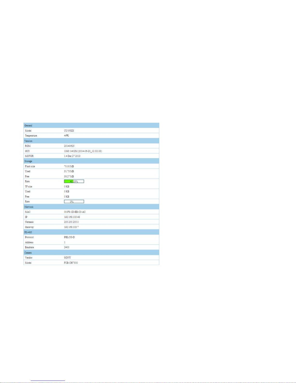
General: Display PTZ or Speed dome’s model\ PTZ or
Speed dome’s inner temperature
Version: ROM display is whole device’s version, this is
main version. GUI display is GUI module’s version, this
module contain interface,PTZ control, protocol. MOTOR
display is motor board’s software version, through this
information can confirm motor board is suitable for main
control module or not.
Storage: Flash file system size display total capacity of
program memory chips,when update program is less than
free-space, can update. SD file system display TF total
capacity,and relevant use condition
Network: Display PTZ’s MAC address\IP\Sub-way
mask\gateway information.
RS-485: Display PTZ protocol,address,baud rate
information
Camera: Display camera’s factory name and model.
Page 32
32
Chapter III OSD menu setup
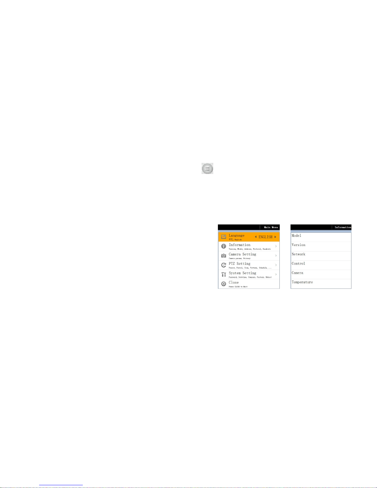
This interface display, call 64 preset or click IE interface PTZ direction control middle , display below interface (Normal control has: Rocker
down/up/left/right, IRIS +/-. Rocker up/down used for control move; left/Right key used for switch parameters , and right key can choose menu,too; IRIS +
used to choose menu item; IRIS - equal to Save and return )
3.1 Main menu
Language:Language setup,Chinese and English two kind language for option.
Information: Display sub-menu, can display version,model,address, protocol,baud rate,network information, temperature etc.
Camera setting: Enter camera normal parameter set sub-menu, can setup
camera’s parameter, privacy mask etc, camera module Automatic Identification.
PTZ setting: Enter PTZ setup sub-menu, can setup preset, patrol, scan, pattern,
schedule,alarm and other function.
System setting: Enter system setup sub-menu, can setup PW,interface
display,network parameters,date time, PTZ video,compass benchmark,factory
reset, system restart etc.function.
3.2 System information
Information:enter system information display
Model: Display the device’s model
Version: Display the device’s all program’s version.
Network: Network parameters display
Control: Protocol & Baud rate
Page 33
33
Camera: Display camera module’s model
Temperature: Display current PTZ inner temperature.
3.3 Camera setup
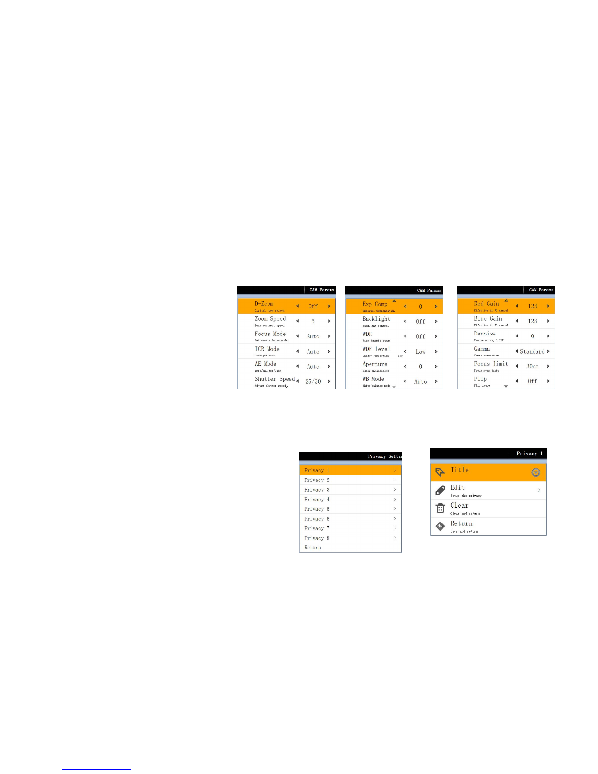
CAM Parameters: Enter camera parameters setup sub-menu
D-zoom: Setup digital zoom. ON/OFF
Zoom Speed: Zoom speed 0-7 adjustable.
Focus Mode: Camera focus mode,auto/manual
ICR Mode: Low light setup, day/night/auto
AE Mode: Manual/Auto/shutter priority/IRIS
priority
Shutter Speed: Shutter level:1-10000 for option.
Exp Comp: Exp Comp setup, ON/OFF
WDR: WDR mode, ON/OFF/AUTO
Aperture: 0-15 adjustable,0 mens off,the greater selected number,the clearer outline of object.
WB Mode: White balance mode, auto/manual/indoor/outdoor/auto tracking.
Red Gain: When white balance mode is Manual mode, can adjust Re gain.
Blue Gain:When white balance mode is Manual mode, can adjust
Blue gain.
Denoise: Used for when image not clear because of low light. 0~5
for option. 0 means close denoise.
Gamma: Gamma correction mode,high/middle/low/direct
line/standard.
Flip: Camera flip, flip video to suitable for device inversion. ON/OFF
Return: Save and return to previous menu
Page 34
34
Privacy setting:Enter privacy mask setting sub-menu.
Privacy setting: 1-8 for option
Title: Enter privacy mask 1,then can setup title
Edit: Setup mask position and size
Clear: Clear setting and return
Save: Save setting and return.
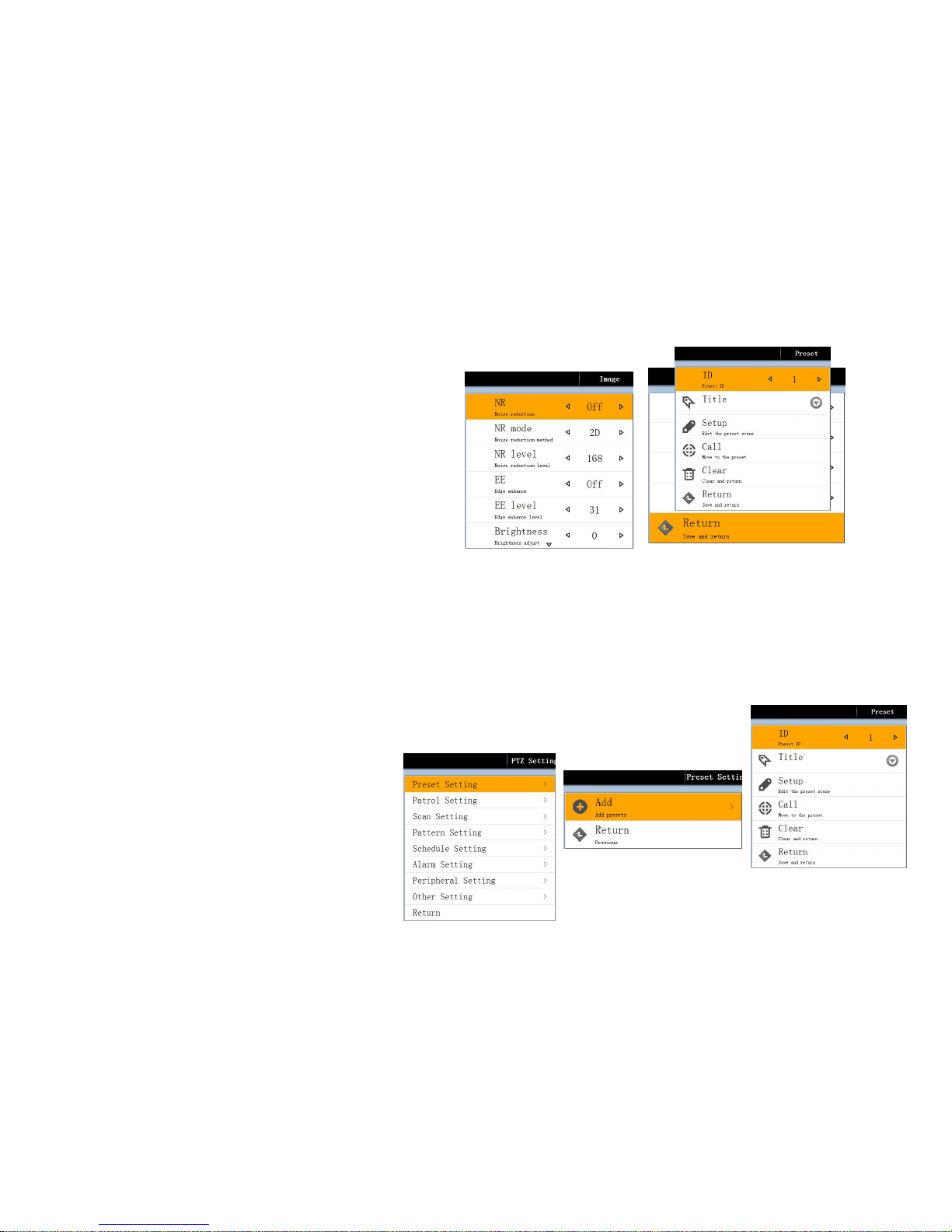
Image Enhance(Back end):Enter image setup sub-menu
NR: Denoise, ON/OFF/AUTO
NR Mode: Setup denoise mode: 2D,3D,3D+,strong noise
reduction,superposition of noise reduction
NR level: 0-168 level
EE: Edge enhance, ON/OFF
EE level: adjust Edge enhance level,0-31
Brightness: -128-+127 adjustable
Contrast: Adjust contrast -128-+127
Stauration: Setting 0-255
Flip: Pan not change, just flip tilt.
Mirror: Pan flip, tilt not change.
3.4 PTZ Setup
Preset setting: Enter Preset setup sub-menu
Add:Add new preset position
ID: Display preset NO.
Tilt: Set preset’s title, it has
Page 35
35
Chinese,English,No.punctuation mark..etc.
Setup: Preset position edit.
Cll: Call preset which already set
Clear: Clear and return
Return: Save and return
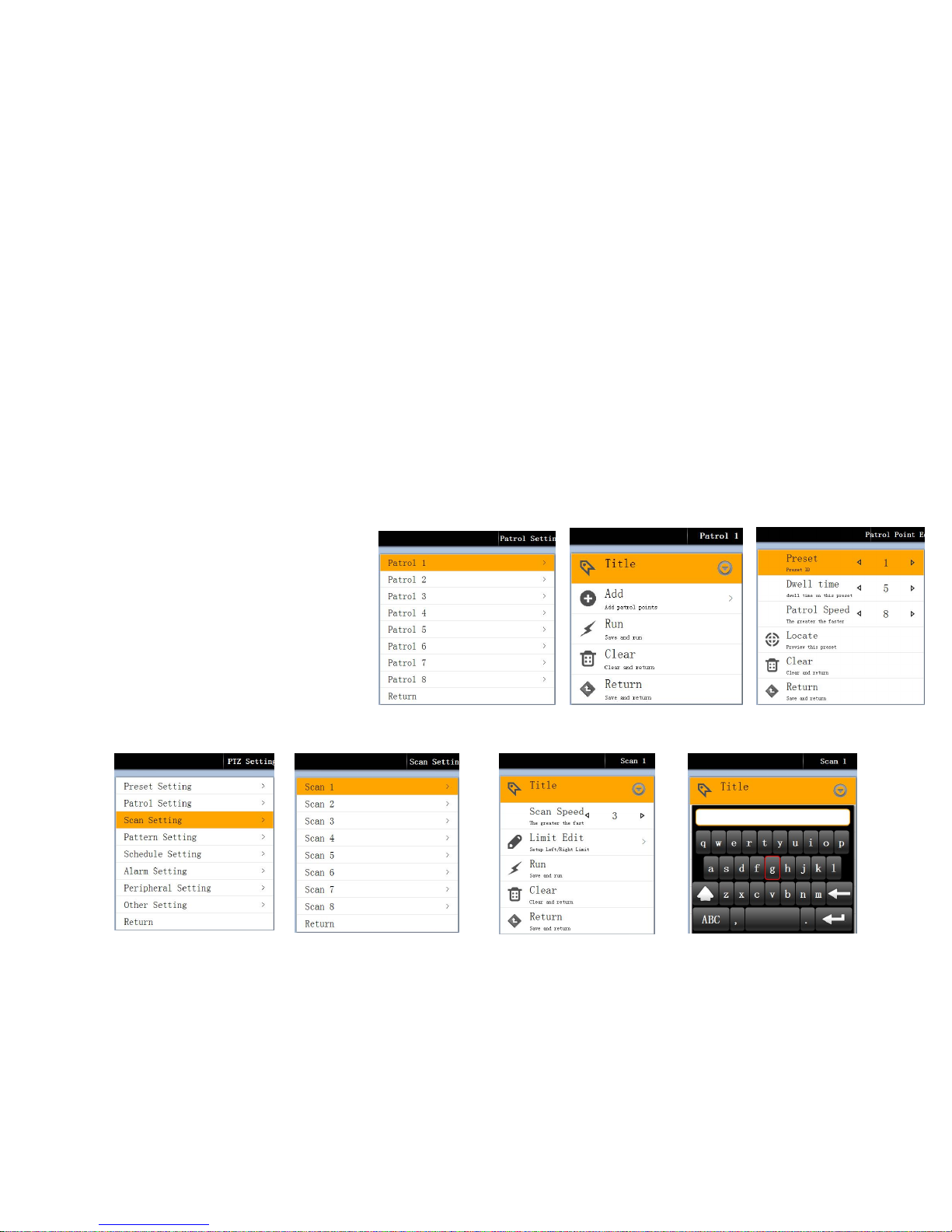
Patrol setting: Enter patrol setup sub-menu
Patrol: 1-8 for option, when run patrol 1, can setup patrol 1
Title: Setup patrol title, it has Chinese and English and No. And punctuation mark. etc.
Add: Enter to patrol edit sub-menu.
Preset: Current position 1-255 preset for option.
Dwel time: Patrol this preset can stop time 5S~
60S for option.
Patrol Speed: Patrol to next position’s speed.
1-8 step for option.
Locate: Preview this preset.
Clear: Clear this configuration and return
Return: Save configuration and return.
Run: Save patrol setting ,and run patrol
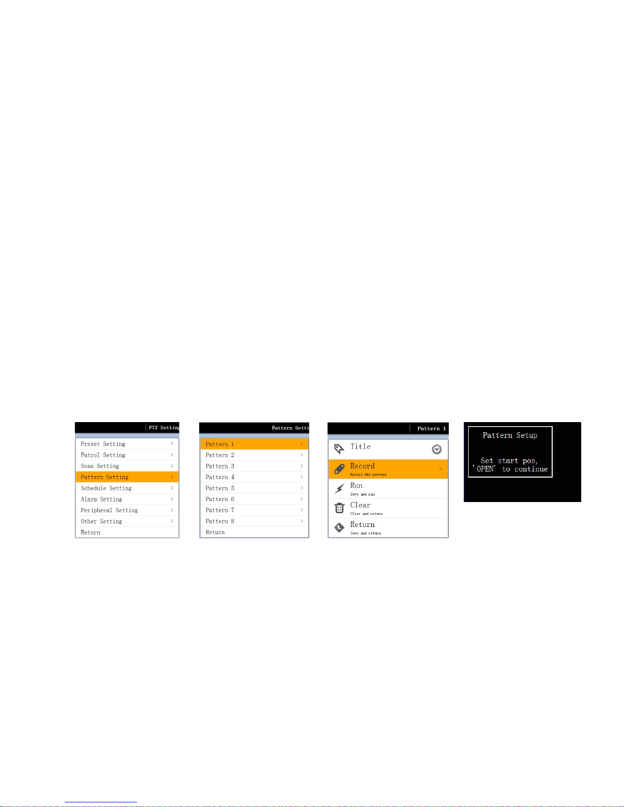
Scanning setup: Enter scanning setup sub-menu
Page 36
36
Scan Setting: Scan No. Choose,1-8 for option.
Scan Speed: Setup scan speed. 1-8 speed for option. Can set each scan.
Limit Edit: Setup scan’s start and end, then when enter, use joystick to move PTZ. Press OPEN key to save current position and return.
Run: Run two point scan function.
Clear: Clear scan setup and return.
Bck to previous menu.
Pattern Setting: Enter pattern setup sub-menu
Pattern No. Edit pattern,1-8 for option.
Tilt: Enter pattern No.,can setup title for pattern,it has Chinese,English,No.punctuation mark..etc.
Record: Record pattern self-learning. Choose start position, press”OPEN” key to continue record.
Run: Save setup and run pattern, after run,then outside menu, joystick can control and let it stop run.
Clear: Clear current pattern.
Retrun: Save setup then return.
Page 37
37
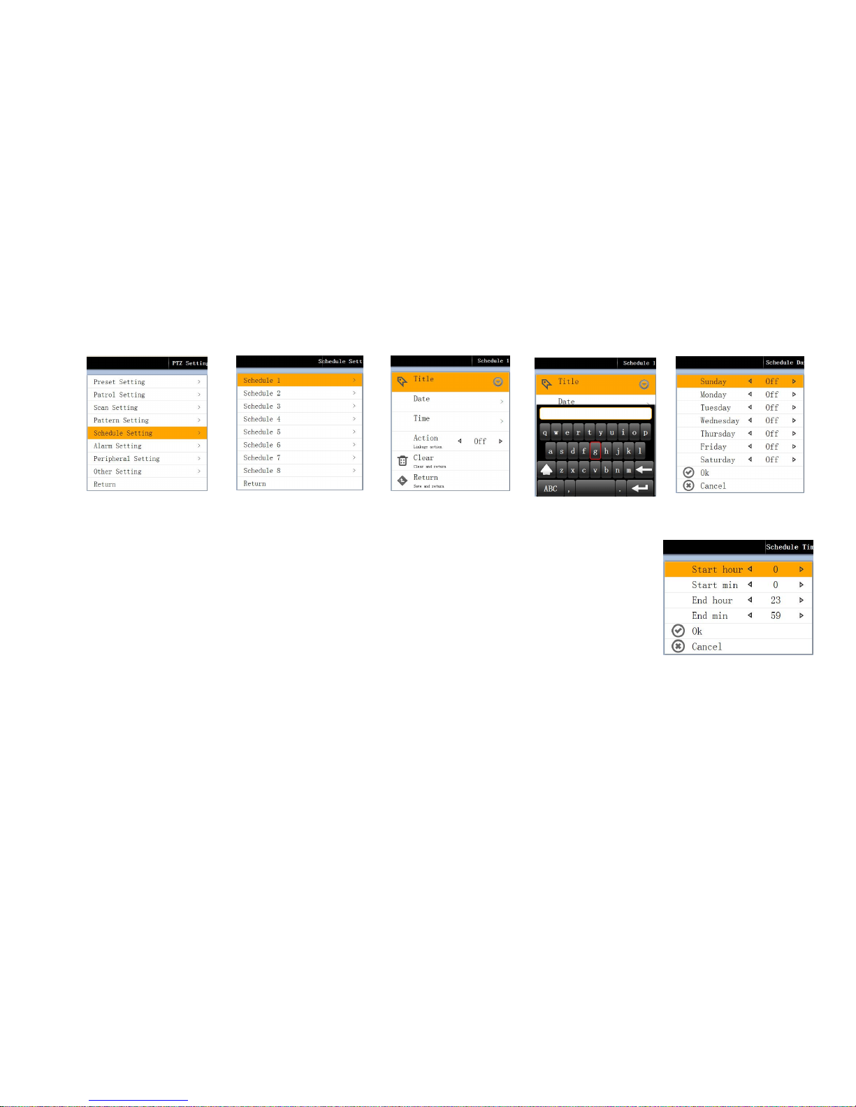
Schedule setting: Enter schedule setting sub-menu
Schedule No.: Schedule 1-8 for option.
Title: Enter schedule No., can setup schedule title,it has Chinese,English,No.punctuation mark..etc.
Date: Schedule edit,setup Sunday--Saturday
Time: Schedule time edit
Start hour: Start time setup, hour choose
Start min: Start time setup, min. choose。
End hour: End time setup,hour choose.
Endo hour: End time setup,min. choose.
Action: Setup schedule action choice. Day mode,night mod,patrol 1-4,pattern 1-4,preset 1-4,scan 1-4,OFF
Clear: Clear configuration and return.
Return: Save configuration and return.
Page 38
38
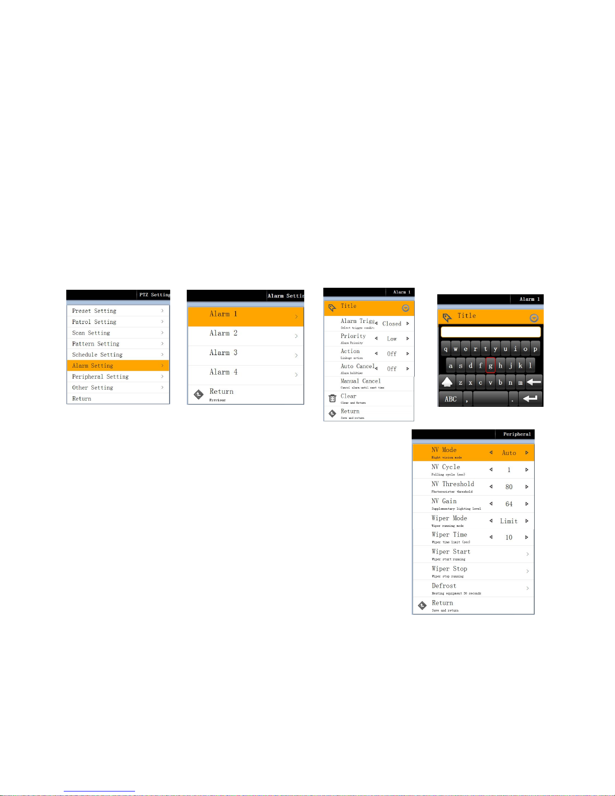
Alarm setting: Enter alarm setup sub-menu
Alarm:1 alarm
Title: Enter alarm title, can setup alarm title,it has Chinese,English,No. Punctuation mark...etc
Alarm Trigger: Choose trigger alarm’s condition, normally open /Normally close for option.
Priority: Setup alarm priority. Highest/High/Middle/Low for option.
Action: Setup linkage, day/night/patrol1-4/pattern1-4/scan1-4/preset1-4,OFF
Auto Cancel: Setup Automatic cancel alarm. 1-10mins for option.
Manual Cancel: Cancel current alarm, until next time trigger.
Clear: Clear configuration and back to previous menu.
Return: Save configuration and back to previous menu.
Peripheral: Enter advanced setup sub-menu
Page 39
39
NV mode: Auto,ON,OFF
Nv CYCLE: Night vision surveillance cycle time setup,1-60s for option.
NV Threshold: Photosensitive resistance strength 0~255 for option.. When light is lower than this value, night vision device will auto open.
NV Gain: Adjust night vision light ,0-64 for option.
Wiper Mode: one ,limit,n time.
Wiper time: Setup wiper working time.10~600 S for option.
Wiper start: Wiper START as setup mode.
Wiper Sotp: Limit or un-limit stop by manual mode
Defrost: Through heart device to defrost, time is 30s.
Return: Save configuration and back to previous menu.
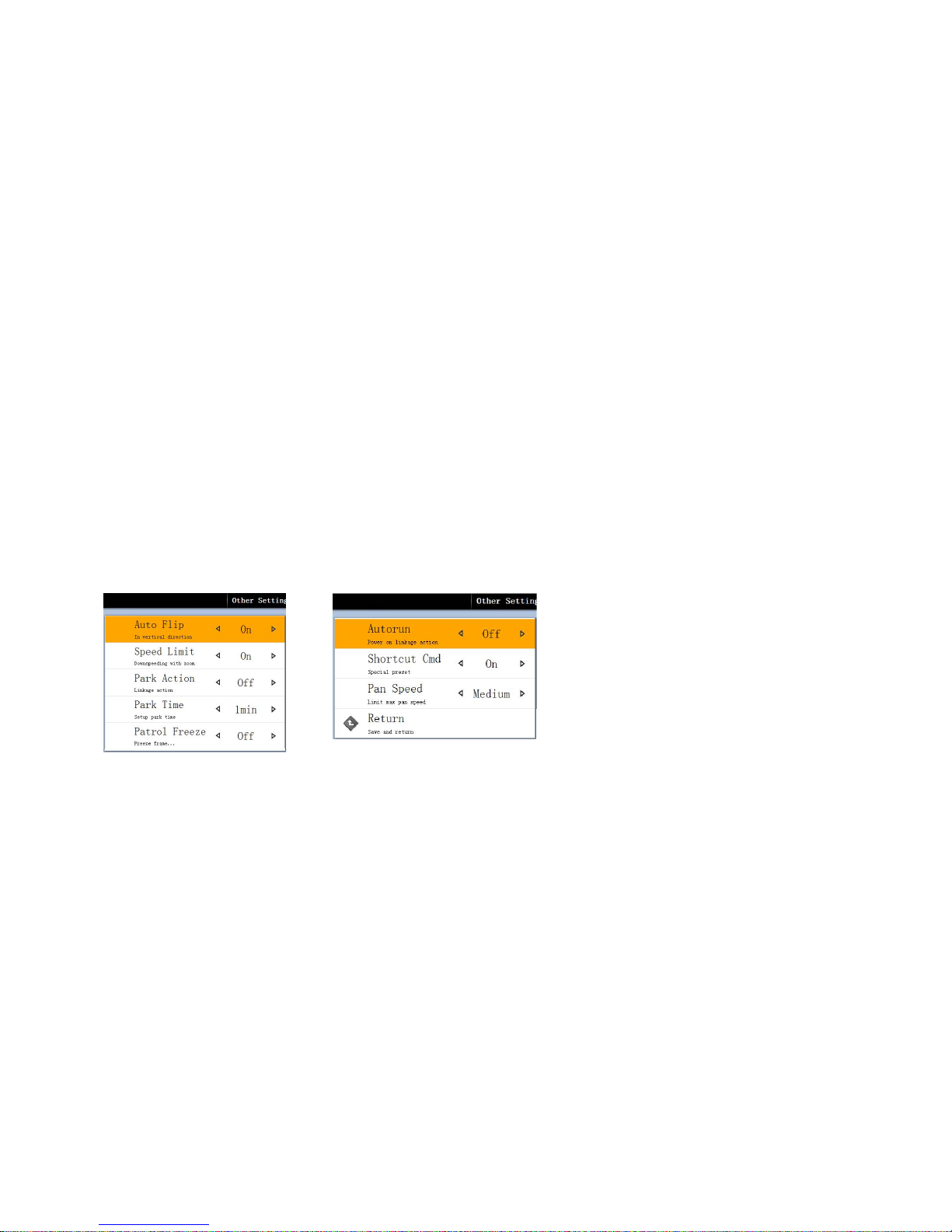
Other setting: Enter other sub-menu
Auto Flip: When camera arrive at tilt position, pan run 180°, ON/OFF for option.
Speed limit: When camera in high zoo, PTZ or speed dome will automatic let speed slow, ON/OFF for option.
Park action: When this option Open, will open park action function. This means when in a while, user do not has any control or active, PTZ or speed
dome will back to the original point. When PTZ or speed dome in a patrol , will not back to original point. If you no need it back to original point, please
let this option OFF.
Page 40
40
Park time: Set park action time,means in how many time if PTZ or speed dome do not be controlled, it will be back to original point, 1-99mins for option.
Patrol freeze: During patrol, freeze image, ON/OFF for option.
Autoron: After power on come to re-set state, day mode/night mode/ patron 1-4/pattern1-4,preset1-4,scanning 1-4 OFF.
Shortcut command: quickly command ON/OFF
Pan speed: Choose pan speed. Max.fast/fast/middle fast/low fast for option.
Return: Save configuration and return
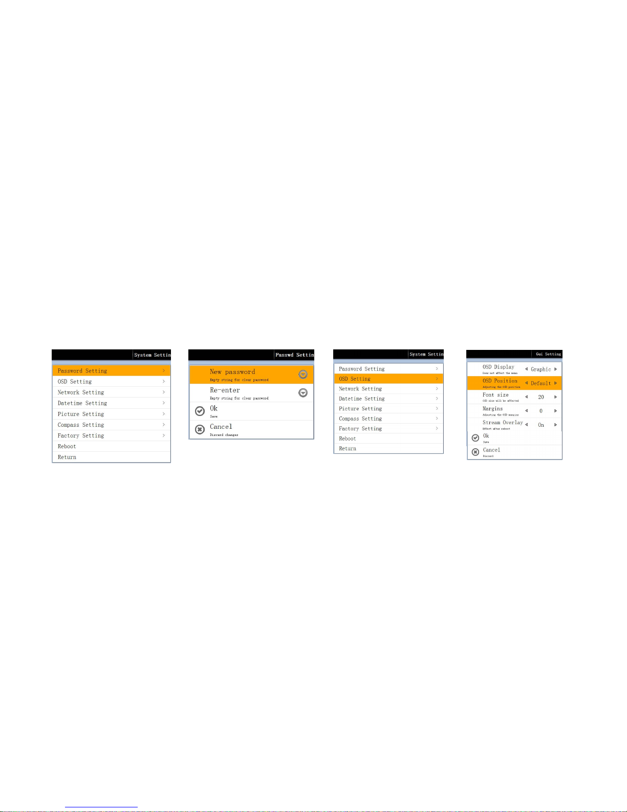
3.5 System setup
:
Enter system setup sub-menu.
Password setting: Enter menu PW setup sub-menu.
New password: Max.8 character. When set 0, can clear PW. It has Chinese, English,No....etc.
Re-enter: Input new PW confirm.
Confirm: Save setting and return.
Canceel: Cancel modify and return.
OSD Setting: Enter OSD interface setup sub-menu.
OSD display: Display and hide for option.
Page 41
41
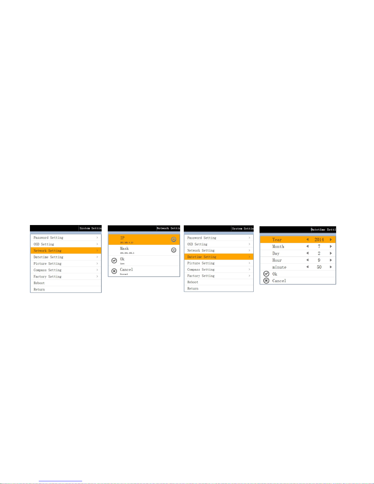
OSD position: Default Top left,Middle top, Top right, left Middle,right,left bottom, right bottom for option.
Font Size: 12-28 for option
Edge: 0-128 for option.
Margins: Save setting and return.
Cancel: Cancel set up and return.
Network setting: Enter network setup sub-menu
IP: Setup PTZ’s IP address
Mask: Sub-net mask setup.
OK: Save and return.
Cancel: Cancel modify and return.
Datetime setting: Enter date time setup sub-menu
Year\month\day\hour\minute: Time setup, user can according to themselves to setup.
OK: Save and return.。
Cancel: Cancel setup and return.
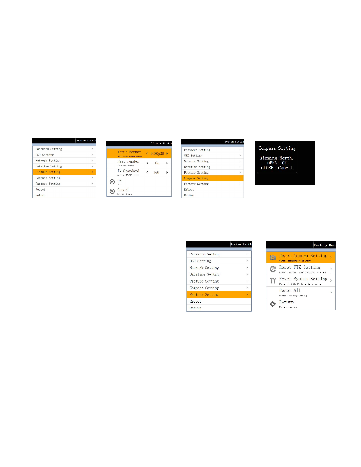
Picture setting: Enter PTZ video setup men-menu.
Page 42
42
Input format:Setup input format:1080P25/1080P30/720P50/720P60 for optional.
OK: Save and return.
Cancel: Cancel setup and return.
Compas setting: Setup North. Correct setup north, When PTZ run, can display current direction. Total 8 direction can display.
Factory setting: Setup back to factory setting sub-menu.
Reset camera setting: Camera parameter setup, privacy mask setup to
factory setting.
Reset PTZ setting: Preset, patrol,scan, pattern, schedule,alarm setup to
factory setting.
Reset All: Reset all the factory setting. Contain Camera setting, PTZ
setting.
Return: Return to previous menu.
Reboot: System re-start.
Page 43

43
Chapter IV PTZ Installation Description
4.1 Safety measures
4.1.1 Qualification of installation or maintenance workers
Submission of qualification certificate for CCTV system install or maintenance, and qualification certificates for relevant works (such as high altitude
operations etc), these workers must have the following elementary knowledge and skills;
Elementary knowledge for CCTV system and components and skills for installing;
Elementary knowledge for LV wiring and LV electronic circuit wiring and operating skills;
Able to read and understand this manual.
4.1.2 Requirements for lifting equipment
Using the safe lifting equipment suitable for site conditions and pan/tilt mounting mode;
The lifting equipment must have the enough lifting height for reaching the specified position for installing purpose;
The lifting equipment must have the excellent safety performances.
4.2 Warning
Forbid to install and operate this product at the dangerous area for storing or using the flammables or explosives.
During the installation and operation of this product, strictly obey all national and local electrical safety codes.
Confirm that the nearby touchable fixtures and this product have been powered off.
The applicable voltage of this product is DC12.V(vehicle-mounted),AC24V(normal PTZ),strictly forbid to apply the voltage higher than the required
directly upon this product.
This product is forbidden to install at the place beyond the specified service conditions.
In this manual, the DC12.V(vehicle-mounted),AC24V(normal PTZ), are generally called the power cable, and RS485 cables are briefly called the
communication cable, and BNC video coaxial cables are briefly called the video cable.
4.3 Ambient requirements
Page 44

44
Temperature:-35℃~55℃ Humidity:90%
Power standard:DC12V/5A
4.4 Cabling safety
The signal transmission lines must keep a distance of at least 50m from high-voltage devices or high-voltage cables.
Outdoor cables should be laid under eaves if possible.
In open fields, cables shall be laid in sealed and earthed underground steel pipes and aerial cabling is forbidden.
In areas with strong thunderstorms or areas with high induced voltage (such as: high-voltage substations), measures like additional installation of
high-power lightning protection devices and lightning rods must be adopted.
The anti-lightning and earthing design of outdoor devices and lines shall be considered together with the anti-lightning requirements of buildings in a
unified way and meet the requirements of applicable national standards and industrial standards.
The system must be equipotentially grounded. The earthing devices must meet the dual requirements of anti-jamming and electrical safety of the system
and may not be connected to the zero line of a high-voltage power grid in a short circuit or mixed manner. When the system is separately grounded, the
ground impedance shall not be greater than 4Ω and the section area of the earth conductor shall not be greater than 25mm2.
This product adopts TVS plate electrode lightning protection technology and may effectively prevent the damage of the device caused by instantaneous
lightning strikes, surges and other types of impulse signals at or below 1.5KW, necessary protective measures shall be provided during outdoor
installation according to the actual condition and on the precondition of assuring electrical safety.
4.5 Installation preparation
4.5.1 Basic requirements
All electrical operations must obey the prevailing latest electrical code, fireproof regulations and relevant standards;
Check whether all accessories are completed according to the packing list, determine whether the applications and mounting mode of this pan/tilt up to
the requirements. Otherwise, please contact the supplier;
Please use this product according to the working environment requirements
4.5.2 Check the space for installing and strength of structures
Page 45
45
Confirm whether there is enough space for installing this product and its members.
4.5.3 Check the structural strength
4.5.4 PTZ power-on self-test
To ensure normal operation of the PTZ on the installation site, please connect the system control lines, video lines and power lines of the PTZ into the
corresponding sockets before installation (the wiring shall strictly comply with the labeling instructions of system control lines, video lines and power lines)
and do power-on self-test. The PTZ will execute factory default setting. If everything is normal after the test, normal installation may be conducted.
4.5.5 Please keep all packing materials of the PTZ
After the PTZ is unpacked, please take good care of the original packing materials of the PTZ so that the PTZ may be packed with its packing material and
mailed to the agent or the manufacturer in case of a problem.
4.6 Installation methods
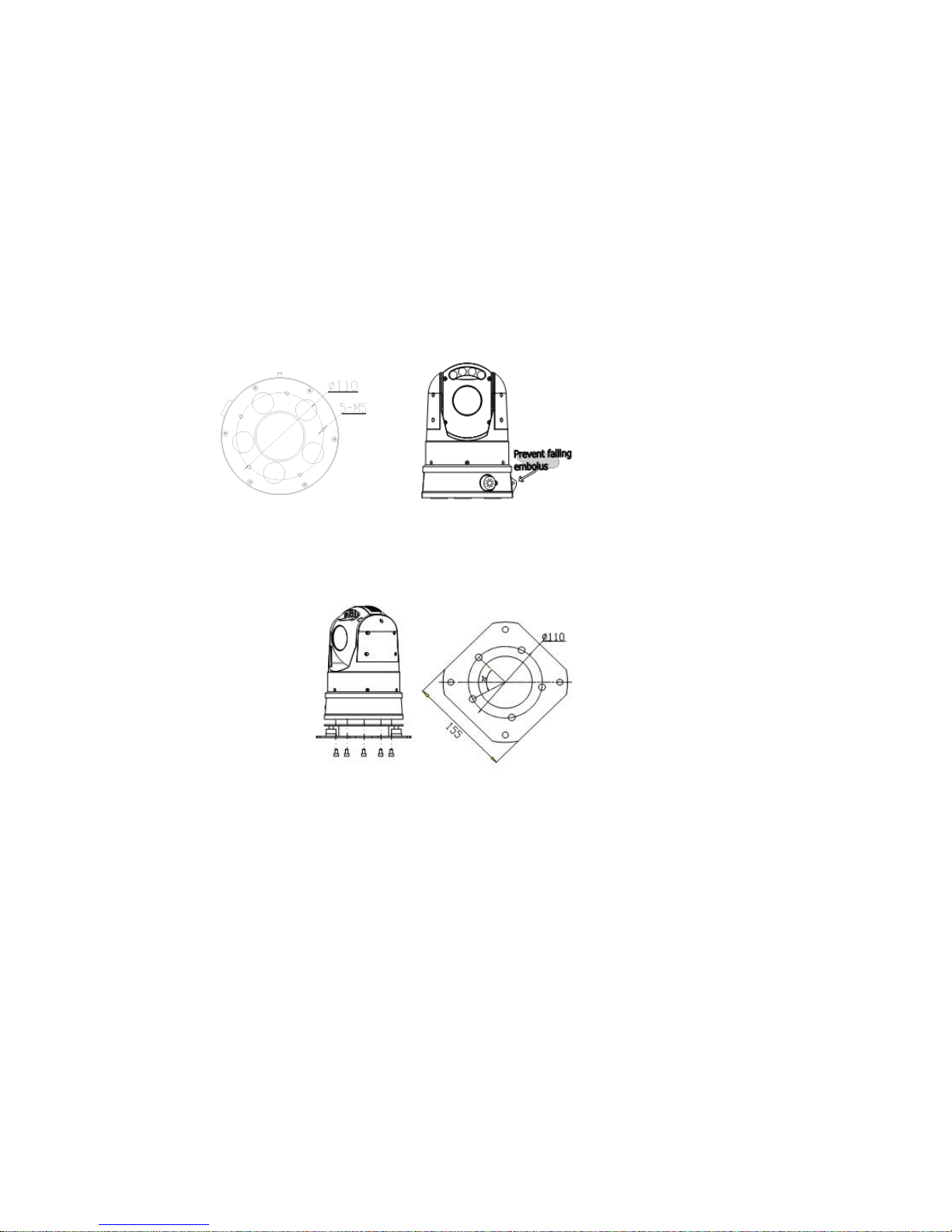
4.6.1 Shock adsorb install ( For optional)
This products bottom can choose magnetic force recombination sucking disc, can powerfully adsorb on the top of car or any device has iron,it is very suitable
for install in many condition and it install very convenient and fast
Page 46
46
Main products chassis Prevent falling embolus
4.6.2 Vehicle-mounted type install (Directly install on the top of Car) for optional
Fixed tray install, M5*8 hexagonal screw contain spring washer & flat gasket , that need through sub-panel inside 5pcs screw,fixed on the main products
chassis. Under bottom board outside has 4pcs Φ9 screw that used to fix products on the fixed device
Note: Device output forbid to inversion, because inversion IP grade will be lower than normal install, it may let the device with water inside
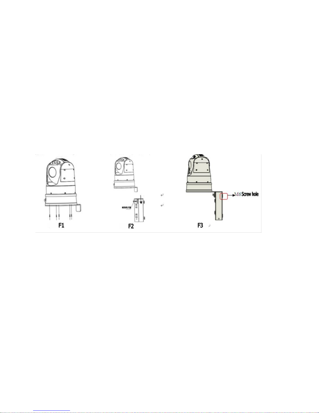
4.6.3 Wall bracket (For option)
Use wall bracket to fix speed dome, it has 2 fixed methods, can use wall install type or a telegraph pole to install:
4.6.3.1 Wall install type
Page 47
47
As below picture: Install steps as below:
Step 1: Strike wall bracket dead plate, use 5pcs (M5*8) hexagon socket head cap screw to fixed with PTZ, as F1
Step 2: Then use dead plate button insert into cradling piece, then use own screw to fasten, as F2
Step 3: Cradling piece use 4pcs * M6 anchoring to fixed with wall, as F3, then finish install
4.6.3.2 Telegraph pole to install:
Install steps as below:
Step 1: Strike wall bracket dead plate, use 5pcs (M5*8) hexagon socket head cap screw to fixed with PTZ, as F1
Step 2: Then use dead plate button insert into cradling piece, then use own screw to fasten, as F2
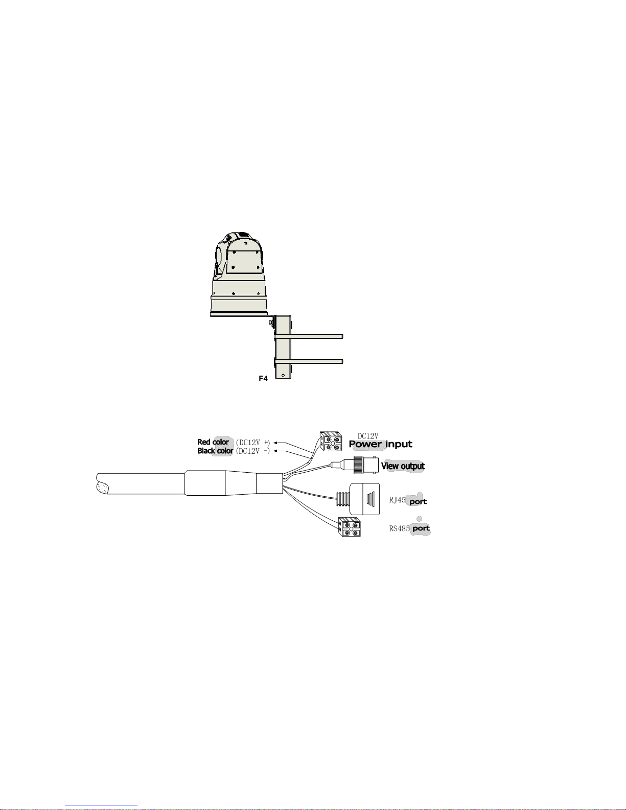
Step3:Cradling piece use 4pcs * M6 anchoring to fixed with wall, as F3,then use hoop to connect bracket pole with telegraph pole, as F4, then install
finish
Page 48
48
F4
4.7 Outgoing lines of PTZ
Cable is as below picture, orange is RS485+, yellow is RS485-
Page 49

49
Annex I: Troubleshooting
Problem Phenomenon
Possible cause
Can’t control PTZ
RS485 line port connect wrong.
Control protocol,ID or baud rate in RS485 of IP camera not same as
PTZ
Can’t connect IP camera
IP camera’s IP address had been modified. If yes, please use ONVIF
Discovery Tool to test IP and re-set IP address.
To find if management PC are in the ful-Mesh of IP camera.
User IE or client can connect succeed,but
can’t display image, image display window
are all dark.
HD camera module can not work normally, may due to different system
(PAL,NTSC)
There are same IP address in the network.
If PC system is Windows 2000,please install SP4patch and DirectX8.0.
Original WEB port and data port had been
modified, now can not access IP camera
User ONVIF Discovery Tool to search and modify port.
If IP camera’s IP address is not the Full-Mesh
of Management PC, can it modify IP camera’s
IP address.
Use ONVIF Discovery Tool to search and modify.
After modify IP address or gateway, can not
access.
After modify IP address,sub-net mask,port ...etc port, please save and
re-start PTZ, then use ONVIF Discovery Tool to search whether
modified IP are correct.
Page 50
50
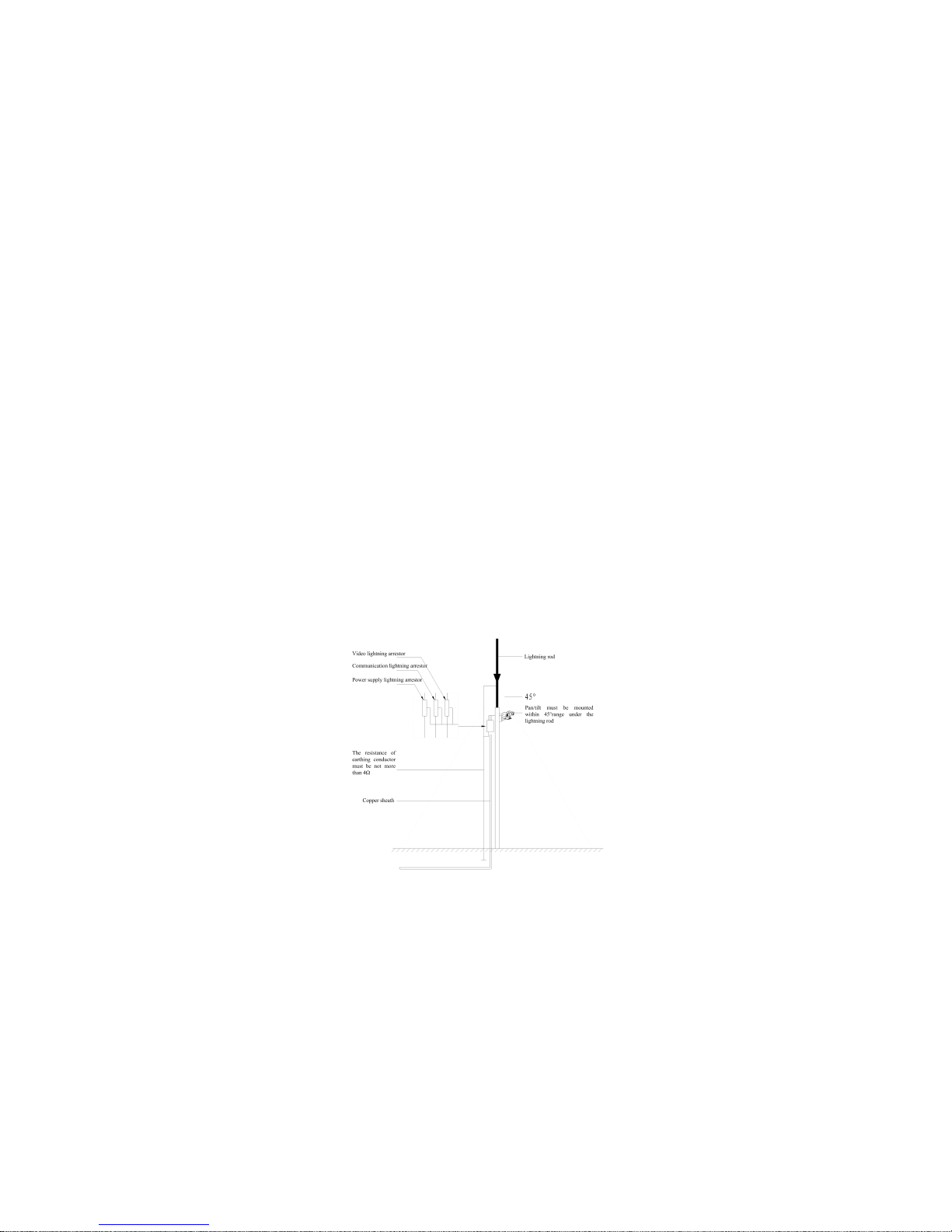
Annex II: Lightning and surge protection
This product adopts TVS pole lightning-proof technology to effectively protect against the damages of pulse signals such as transient lightning below 1.5KW,
and surge etc to equipment. However, if mounted outdoor, the necessary protective measures must be provided as required:
The signal line must be kept away from HV equipment or HV cable at least 50m
Try to wiring outdoor along the route under the eaves.
At open space, the wiring must be buried with closed steel pipe; the steel pipe should be earthed at one point, strictly forbid to use the aerial wiring.
At high thunderstorm area or high induction voltage zone (such as HV substation), the protective measures such as adding of additional high power
lightning-proof device and lightning arrestor etc must be used.
The outdoor devices and circuit lightning-proof and earth design must be combined with the lightning-proof requirements for buildings, and comply with
the relevant national and professional standards.
The system must be equal potentially earthed. The earth device must comply with both system anti-interference and electrical safety requirements, and
not short-circuit or mixed with zero line of strong current grid. When the system is individually earthed, its earth impedance should be not more than 4Ω,
with the section area of earth conductor not more than 25mm2.
Page 51

51
Annex III: Maintenance of the terms of service
1、Warranty terms
Within one year after delivered, if found any defects caused by materials or workmanships, the factory shall be responsible for free repair or replace;
The warranty period of all repaired or replaced parts shall be 90 days since delivered;
The problems due to force majeure (such as war, earthquake, and lightning), wrong or misused operations and modification, normal wearing or
accidents are out of warranty;
The manufacturer shall be not responsible for damages or loss due to specified using or applications of product. The liability of manufacturer for
product concerning breaching, negligence or tort shall be not more than the sale amount of product, and not liable for any special, sudden or
subsequent damages due to any other causes;
If found any problems on the product out of warranty period, our company may provide the paid maintenance service for its whole life.
2、Preconditions
Within warranty period, for any products for repairing, the buyer must contact the manufacture to get the repair number (RAN), and accompany with the
following product information;
Model No. and serial number;
Delivery date, order No., sale ordering No. or manufacturer invoice number;
Detailed problems
If there are any disputes for above mentioned warranty terms, please attach the explanations in written when returning the product.
3、Return
For speedup the repair of returned product, please firstly contact the manufacturer to get the RAN number, then return the product to our company. And
clearly mark with RAN number. The shipment mode of returned product must be consistent with that mailed to our company. Only the single-trip fee from
manufacturer to the user shall be borne by our company.
Print may let this manual’s picture is a litter bit different with real products.
Due to product upgrading, the design, specification and parameters of the product are subject to change without notice.
There might be some printing omissions and errors and description errors although we have carefully checked the content of this manual before
printing.
We reserve the right of final interpretation to this manual.
 Loading...