

Page 1
Wireless Radio Commander FA-WRC1M
Before use
Camera software [1]
Before use [2]
Features of the Wireless Radio Commander [3]
Identifying parts [4]
Indicators on the screen [5]
Preparations
Turning on the power [6]
Pairing with a Wireless Radio Receiver [7]
Shooting
Using MENU items [8]
Groups [9]
Wireless flash shooting [10]
Remote release shooting [11]
Notes on use
Notes on use [12]
[1] Before use
Camera software
Update the software of your camera to the latest version before use.
Page 2

Refer to the dedicated support site for information on camera compatibility.
[2] Before use
Before use
This product can be used in combination with Sony Interchangeable Lens Digital Cameras
that have a Multi Interface Shoe.
Some functions may not be available depending on the model of the camera you use. Refer
to the Sony website for your region for details on this product’s compatibility with your
camera.
Along with this manual, refer to the operating instructions of your camera.
This product is designed to be dust and moisture-resistant, but is not
waterproof or splash-proof. When you use the product in rainy conditions,
do not let the product get wet.
Locations to avoid
Regardless of whether this product is in use or in storage, do not place it in any of the
following locations. Doing so may cause a malfunction.
In extremely hot locations
In locations such as a car parked in the sun, the product may become deformed resulting
in a malfunction.
Under direct sunlight or near a heater
The product may become deformed resulting in a malfunction.
In locations with excessive vibration
Near strong magnetic fields
In sandy or dusty areas such as on the beach
Be careful not to let sand or dust get inside the product when using it on the beach or
other sandy areas. This may cause a malfunction.
Flash sync terminals
Flashes that have a sync terminal with reversed polarity can be used with this product.
Use flashes with a sync voltage of 400 V or lower.
Turn off the flash connected to the sync cord when you connect the sync cord to the
(flash sync) terminal. Otherwise, the flash may emit light when the sync cord is
connected.
When you are using a flash connected to the (flash sync) terminal, set the shutter
speed to the slower of the following values or slower.
The flash sync speed of the camera
The shutter speed recommended by the flash
Page 3

Communication distance
The communication distance between this product and the Wireless Radio Receiver (sold
separately) is approximately 30 m (98.4 ft.).
The distance given above applies under conditions where there are no obstacles,
shielding, or radio wave interferences.
The communication distance may be shorter depending on the positioning of the
products, the ambient environment, and weather conditions.
Trademarks
“Multi Interface Shoe” is a trademark of Sony Corporation.
[3] Before use
Features of the Wireless Radio Commander
You can shoot images with multiple flash units that are wirelessly connected, or you can
shoot images with multiple cameras that are controlled remotely by using this product and
the Wireless Radio Receiver (sold separately).
Wireless flash shooting
The Wireless Radio Commander controls genuine Sony flash units (sold separately,
hereinafter referred to as “flash”) attached to Wireless Radio Receivers (sold separately) via
radio wave. Flash units can be divided into a maximum of five groups using the Wireless
Radio Receivers. You can shoot with flash units in various situations by setting the flash
mode or flash’s power level for each group. The Wireless Radio Commander supports TTL
flash shooting, manual flash shooting, and High-speed sync (HSS) shooting, etc. with
multiple flash units.
Remote release shooting
The Wireless Radio Commander can make multiple cameras release their shutters at the
same time so that you can shoot one subject from multiple angles simultaneously.
A Wireless Radio Receiver (sold separately) and a Multi Terminal Connecting Cable (sold
separately) are required for remote release shooting.
[4] Before use
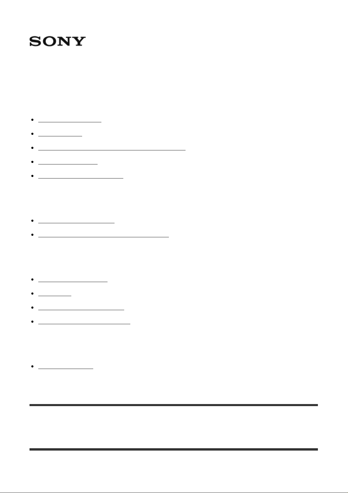
Identifying parts
Page 4
Control panel
1. LINK lamp
2. LCD panel
3. (flash sync) terminal
4. Multi/Micro USB Terminal
Connects the product and the camera for remote release shooting.
5. Lock lever
6. Multi Interface foot
7. Battery cover
8. Fn (function) button
Switches the display to the settings adjustment screen (Quick Navi screen), letting
settings be changed quickly.
9. SHUTTER button
Releases the shutter of the camera to which a Wireless Radio Receiver is connected
during remote release shooting.
10. TEST button
Tests the flash before shooting.
11. MENU button
12. (LCD illuminator) button
Turn the lighting of the LCD panel and the areas around the buttons on or off.
Page 5
13. Power switch
When the switch is set to “LOCK,” buttons including the control wheel become inactive
to avoid unintended operations.
14. Center button
Confirms selections on the menu screen.
15. Control wheel
Moves the cursor and changes values on the Quick Navi screen or menu screen.
When shooting, flash compensation and flash level settings are assigned to the left
button, and receiver settings are assigned to the right button.
How to use the control wheel
You can perform operations corresponding to the on-screen display using the control wheel.
Shooting screen
Flash compensation and flash level settings are assigned to the left button, and receiver
settings are assigned to the right button.
Quick Navi screen
You can select an item by moving the cursor (which item is highlighted) using the
top/bottom/right/left button on the control wheel, and change the value by turning the wheel.
Menu screen
You can select an item by moving the cursor using the top/bottom/right/left button on the
control wheel, and change the setting by pressing the center button.
[5] Before use
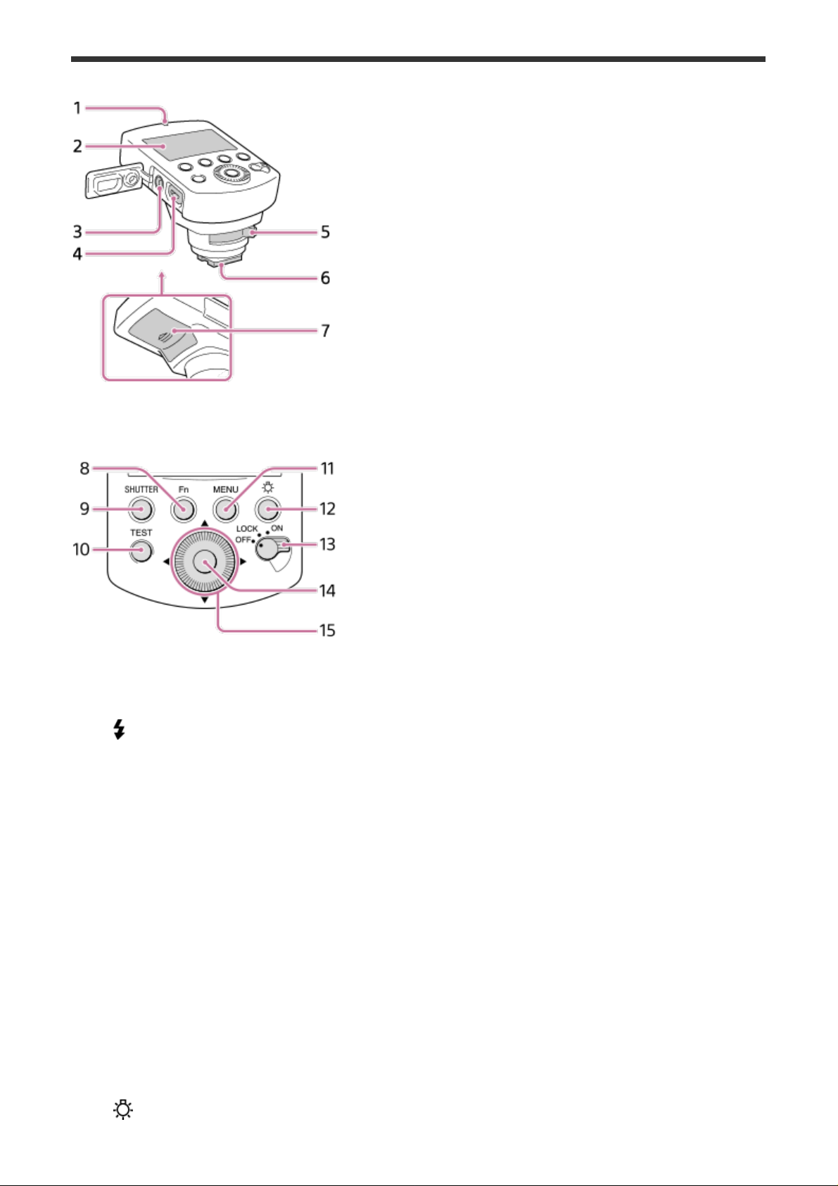
Indicators on the screen
TTL mode
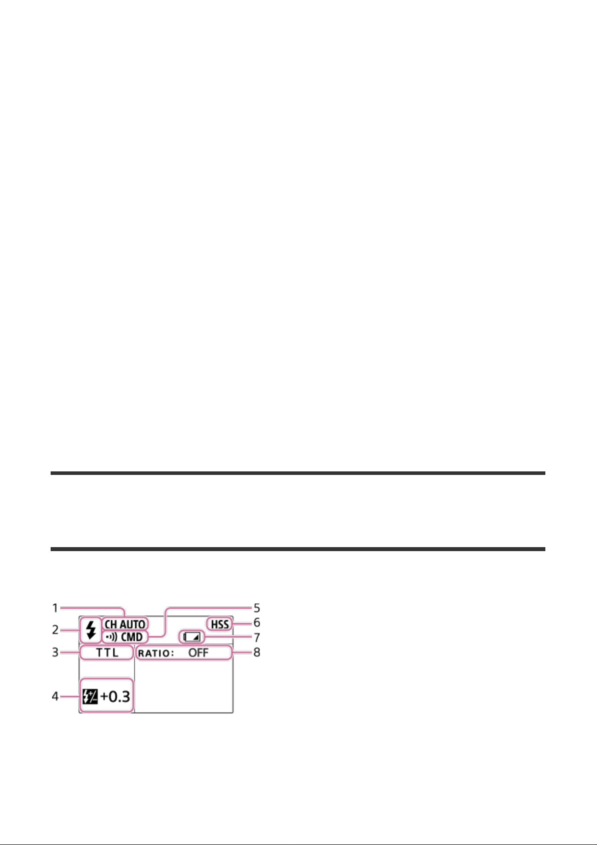
TTL mode (ratio control)
Page 6
MANUAL mode
MANUAL mode (ratio control)
GROUP mode
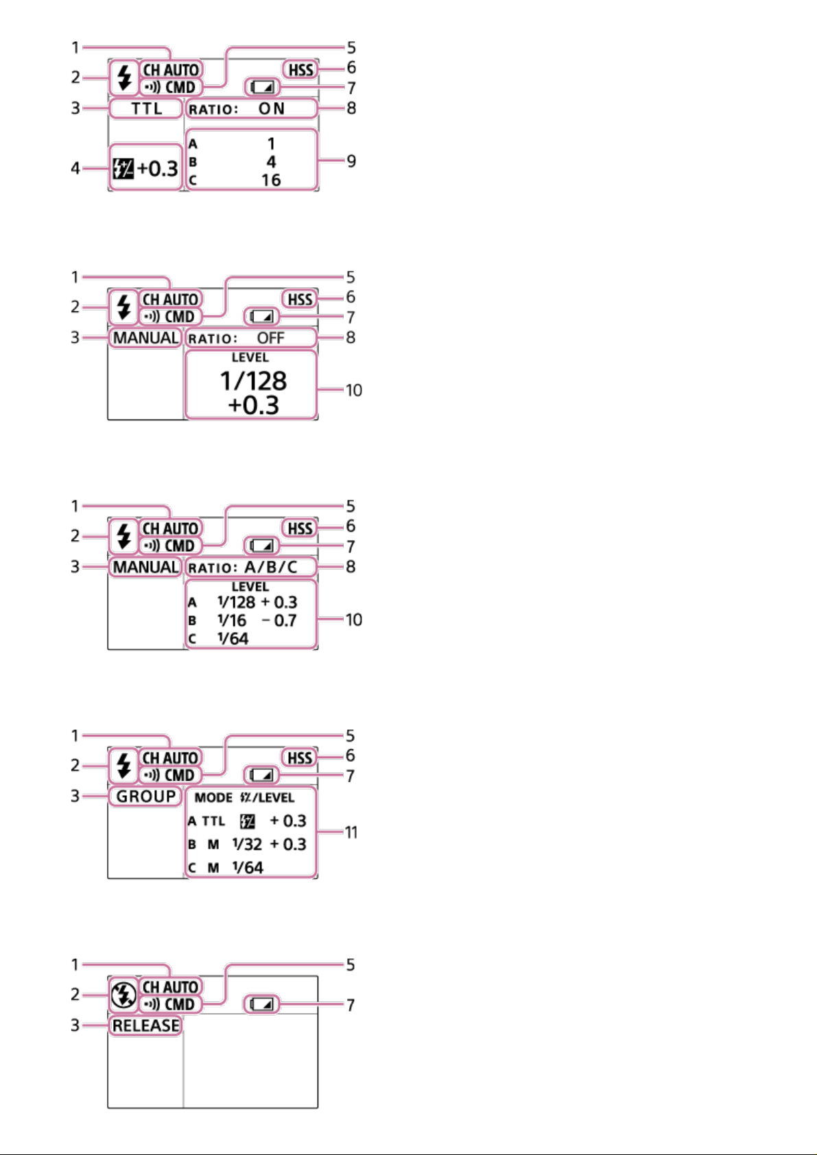
RELEASE mode
Page 7

1. Communication channel
2. Wireless flash mode
is displayed when the product is in wireless flash mode. Otherwise, is displayed.
3. Shooting mode
4. Flash compensation
5. Communication mode
6. High-speed sync shooting
7. Low-battery indicator
Appears when the batteries are low. It is recommended that you change the batteries
shortly.
8. Ratio setting
9. Lighting ratio
10. Flash level
11. Group settings (flash mode and flash compensation/flash level)
Quick Navi screen
Press the Fn button to switch the display to the settings adjustment screen (Quick Navi).
You can change the values quickly using the control wheel.
Menu screen
The menu screen is displayed when you press the MENU button. You can change various
settings for the product.
[6] Preparations
Turning on the power
You can use the following types of batteries with this product.
Two LR6 (AA-sized) alkaline batteries
Two AA-sized rechargeable nickel-metal hydride (Ni-MH) batteries
Always ensure that rechargeable nickel-metal hydride batteries are charged with the
specified charger.
1. Open the battery cover and insert batteries (sold separately).
Insert the batteries into the battery chamber as illustrated ( ).
( indicates the direction of the batteries.)
2. Attach the product to the camera.
Ensure that the product is turned off.
Remove the caps from the Multi Interface foot of the product and from the Multi
Page 8

Interface Shoe of the camera.
1. Turn the lock lever to “RELEASE” while pressing the release button (A) on the
lever.
2. Firmly insert the Multi Interface foot all the way into the Multi Interface Shoe of the
camera in the direction of the arrow.
3. Firmly turn the lock lever to “LOCK” to secure the product.
3. Set the power switch to “ON.”
To remove the product from the camera
Turn off the power of the product and perform Step 2-1 to remove the product.
When you are not using the product or you are using the product alone held in your hand,
reattach the cap to the Multi Interface foot.
[7] Preparations
Pairing with a Wireless Radio Receiver
To shoot images with wireless flash shooting or remote release shooting using this product,
the product must be paired with a Wireless Radio Receiver (sold separately).
Perform pairing within 1 m (3.3 ft.) of the Wireless Radio Receiver.
You can pair this product with up to 15 Wireless Radio Receivers.
1. Turn on the product, then select MENU button - [PAIRING] - [ADD] and press the
center button (A).
The LINK lamp on the product will flash in green and the pairing screen will appear.
Page 9

2. Ensure that the Wireless Radio Receiver is turned off, and then press and hold the
ON/OFF button on the Wireless Radio Receiver for seven seconds or more.
The Wireless Radio Receiver will turn on and the LINK lamp will flash in green.
3. When pairing is finished, the LINK lamp on the Wireless Radio Receiver will light up in
green.
The screen of the product will display the number of Wireless Radio Receivers that
have just been paired.
If you want to pair this product with two or more Wireless Radio Receivers, repeat
steps 2 through 3 for each Wireless Radio Receiver.
4. Press the center button.
Pairing will end and the LINK lamp on the product will light up in green.
If the LINK lamp on the product or the Wireless Radio Receiver lights up in red after the
pairing procedure, the products have not been paired successfully. Retry the procedure
Page 10

starting from Step 1.
To confirm the paired receivers/unpair the receivers
Select MENU button - [PAIRING] - [LIST] on the product.
When communications between the product and the Wireless Radio Receiver are available,
is displayed.
To unpair a receiver, set the cursor on (Delete) for the Wireless Radio Receiver to be
unpaired, and then press the center button. When you set the cursor, the LINK lamp on the
corresponding Wireless Radio Receiver will flash.
Unpair a Wireless Radio Receiver while it is turned on.
[8] Shooting
Using MENU items
You can use MENU items to change and confirm the settings of both this product and paired
Wireless Radio Receivers (sold separately).
1. Press the MENU button to display the menu screen. Set the cursor on the desired item
and press the center button (A).
HSS (High-speed sync)
Turns High-speed sync on/off and changes the flash level settings.
RECEIVER SET (Receiver settings)
Page 11

Changes and displays the settings of the paired Wireless Radio Receivers.
When you set the cursor on each item, the LINK lamp on the corresponding Wireless Radio
Receiver will flash.
Settings that can be changed or confirmed
NAME (Name)
The name of the Wireless Radio Receiver is displayed.
LINK (Link status)
When communications are available, is displayed.
GP (Group)
You can check or change the group for the Wireless Radio Receiver.
The group can be changed only when the REMOTE lamp on the corresponding Wireless
Radio Receiver is lit up.
When the group is set to [OFF], the flash (sold separately) attached to the corresponding
Wireless Radio Receiver will not be used during wireless flash shooting.
ZOOM (Flash coverage)
You can check or change the zoom setting (flash coverage) for the flash attached to the
corresponding Wireless Radio Receiver.
The zoom setting (flash coverage) can be changed only when the zoom setting for the
flash is set to AUTO.
To change the settings
1. Set the cursor on GP (group) or ZOOM (flash coverage) for the desired Wireless Radio
Receiver using the top/bottom/right/left button on the control wheel, and then press the
center button.
2. Change the setting by turning the control wheel, and then press the center button.
CH SET (Channel setting)
Sets the channel used for wireless communication. When [AUTO] is selected, the most
appropriate channel according to the surrounding radio wave conditions will be selected
each time the product is turned on.
PAIRING (Pairing)
Pairs this product with a Wireless Radio Receiver.
Page 12

TEST (Test flash)
Sets the mode for the test flash.
LEVEL STEP (Level step)
Sets the amount by which the flash level changes.
POWER SAVE (Power save time)
Sets the time to elapse before automatically switching to power save mode.
VERSION (Version)
Displays the version of this product’s software and the paired Wireless Radio Receivers’
software.
RESET (Reset)
Resets the settings for each flash mode and flash level settings.
Values for MENU items will not be reset.
INITIALIZE (Initialize)
Resets this product to the factory settings.
Pairing information will also be deleted.
[9] Shooting
Groups
You can divide paired Wireless Radio Receivers in a maximum of five groups and set the
flash mode or power level for each group.
You can choose how to set the group by switching the status of the REMOTE lamp on the
Wireless Radio Receiver.
To switch the group assignment method
1. Turn the REMOTE lamp on or off by pressing and holding the GROUP button on the
Wireless Radio Receiver for two seconds or longer.
Page 13

How to change the group using the product
1. Turn on the REMOTE lamp on the Wireless Radio Receiver.
2. Select MENU button – [RECEIVER SET], and then select and change the group of the
desired Wireless Radio Receiver.
How to change the group using the Wireless Radio
Receiver
1. Turn off the REMOTE lamp on the Wireless Radio Receiver.
2. Turn on the desired GROUP lamp by pressing the GROUP button on the Wireless
Radio Receiver repeatedly.
[10] Shooting
Wireless flash shooting
You can perform wireless flash shooting in various flash modes using flashes (sold
separately) attached to paired Wireless Radio Receivers (sold separately).
Make the following settings on the camera.
Shooting mode: [Program Auto], [Aperture Priority], [Shutter Priority], or [Manual
Exposure]
Flash mode: [Wireless]
Note
On the flash attached to the Wireless Radio Receiver, set the flash mode to TTL and the
flash coverage (zoom) to AUTO.
If you are using an HVL-F32M Flash, set the flash level of the group that includes the
HVL-F32M to 1/16 or higher when performing High-speed sync (HSS) shooting in
MANUAL mode.
To change the shooting mode and flash settings
1. Press the Fn button.
2. Set the cursor on the shooting mode (A) or another item using the top/bottom/right/left
Page 14

button on the control wheel, and then select the desired mode by turning the wheel.
TTL (TTL flash shooting mode)
The flash level is set automatically based on a value metered by the camera. You can divide
receivers into up to three groups (A/B/C).
Items that can be changed
Ratio
You can set the lighting ratio for each group.
Flash compensation
MANUAL (Manual flash shooting mode)
The flash level is set manually. You can divide receivers into up to three groups (A/B/C).
Items that can be changed
Flash level
You can set the flash level for each group.
GROUP (Group flash shooting mode)
The flash mode is set for each group. You can divide receivers into up to five groups
(A/B/C/D/E).
Page 15

Items that can be changed
Flash mode
You can set the flash mode for each group.
The flash modes for groups A, B, and C can be set to [TTL] or [MANUAL]. The flash modes
for groups D and E are locked to [MANUAL].
Set the flash mode to [OFF] if you do not want the flashes in the group to be used.
Flash compensation (only for groups set to [TTL] mode)
Flash level (only for groups set to [MANUAL] mode)
[11] Shooting
Remote release shooting
You can perform remote release shooting using this product by connecting it to a paired
Wireless Radio Receiver (sold separately) and a camera.
1. Connect the Multi/Micro USB Terminals of the Wireless Radio Receiver and the camera
using a Multi Terminal Connecting Cable (sold separately).
2. Press the Fn button on the product.
3. Set the cursor on the shooting mode (A) using the top/bottom/right/left button on the
control wheel, and then select [RELEASE] by turning the wheel.
4. Press the SHUTTER button to shoot.
If the Multi/Micro USB Terminals of the product and the camera are connected using
a Multi Terminal Connecting Cable, the connected camera will also perform
shooting.
Page 16

To shoot by pressing the camera’s shutter button
You can perform remote release shooting by pressing the shutter button on the camera to
which the product is attached.
Attach the product to the Multi Interface Shoe of the camera, and then press the camera’s
shutter button.
Set the camera’s [Flash Mode] to [Wireless].
You do not need to connect the Multi/Micro USB Terminals of the product and the camera
using a Multi Terminal Connecting Cable.
Note
To use a flash (sold separately) during remote release shooting, attach the flash to the
camera’s Multi Interface Shoe. The flash cannot be used if it is attached to the Multi
Interface Shoe on the Wireless Radio Receiver.
[12] Notes on use
Notes on use
Product
Do not put the camera inside a bag, etc. with the product attached. This may cause the
camera and the product to malfunction.
When this product and the camera are attached, do not carry them by holding the product.
This may cause a malfunction.
When closing the battery cover, push it in firmly while sliding it all the way across. Be
careful not to catch your finger in the battery cover when closing it. This may cause your
finger to be injured.
Batteries
When using alkaline batteries, the battery level displayed on the LCD panel may be lower
than the actual battery level and the low-battery indicator may appear on the screen
depending on the temperature and storage conditions. The displayed battery level may
revert to the correct value after the product has been used for a while.
When using nickel-metal hydride batteries, the performance of the batteries may be
decrease suddenly once the remaining level has become low. During shooting, just the
low-battery indicator may blink on the screen after which the product can no longer be
used, or the product may turn off suddenly after the low-battery indicator starts blinking.
Remove and store the batteries when you do not intend to use the product for a long
period of time.
Page 17

Temperature
This product is designed for use under temperatures between 0°C and 40°C (32°F and
104°F).
Do not expose the product to extremely high temperatures (e.g. under direct sunlight
inside a vehicle) or high humidity.
To prevent moisture from condensing inside the product when you bring the product
directly from a cold to a warm location, first put the product inside a plastic bag and seal it
after removing the air from the bag. Then, bring the plastic bag and the product into the
room, and take the product out of the plastic bag after the temperature of the product has
reached the ambient temperature.
The performance of the batteries decreases at colder temperatures. Consider using new
batteries or spare batteries that have been kept warm instead. The low-battery indicator
may blink even when there is some power left in the batteries at cold temperatures. The
batteries will regain some of their capacity when warmed to a normal operating
temperature.
Other precautions
When storing, remove the batteries from the product. Storing the product with the batteries
inside may cause ignition or leakage.
Maintenance
Remove this product from the camera. Clean the flash with a dry, soft cloth. If there is sand
on the surface of the product, wiping it will damage the surface. Remove sand gently using a
blower. In the case of stubborn stains, wipe gently using a cloth lightly moistened with cold or
lukewarm water, and then wipe the product clean with a dry, soft cloth. Never use strong
solvents such as paint thinner, benzine, or alcohol, as these will damage the surface finish.
 Loading...