

Page 1
ECM-Z60
SECTION 1
GENERAL
This section is extracted from
instruction manual.
SERVICE MANUAL
Ver 1.0 2000.2
SPECIFICATIONS
Type Electret condenser microphone
Dimensions Microphone parts:
16 × 106 × 22 mm (21/32 × 41/4 × 7/8 in.)(diameter/
length/height)
(Maximum width of stand: 26 mm (11/16 in.))
Battery box parts:
40 × 16.5 × 46 mm (w/h/d)
(15/8 × 21/32 × 113/16 in.)
Mass Microphone parts (including cord):
Approx. 21 g (0.75 oz.)
Battery box parts (including lithium battery and
cord):
Approx. 17 g (0.6 oz.)
Cord Microphone parts:
OFC litz cord (1 cord shielded)
1.5 mm (1/16 in.) dia.
Length: approx. 1 m (393/8 in.)
Battery box parts:
OFC litz cord (2 core shielded)
2.2 mm (3/32 in.) dia.
Length: approx. 0.3 m (117/8 in.)
Supplied accessories
Battery box (1)
US Model
Canadian Model
AEP Model
E Model
Frequency response
100 -10,000 Hz
Directivity Super-directional
Output impedance
2.8 kΩ ± 30 %
Sensitivity Open circuit output voltage
level –36 ± 3.5 dB
0 dB = 1 V / Pa, 1,000 Hz
(1 Pa = 10 µ bar = 94 dB SPL)
Battery life Approx. 300 hours (with Sony CR2025 lithium
battery (not supplied)
Maximum sound pressure input level
Approx. 102 dBSPL
1 % wave distortion at 1,000 Hz
(0 dBSPL = 2 × 10 -5 Pa)
Operating temprerature range
0 °C –40 °C (32 °F –104 °F)
Design and specifications are subject to change without notice.
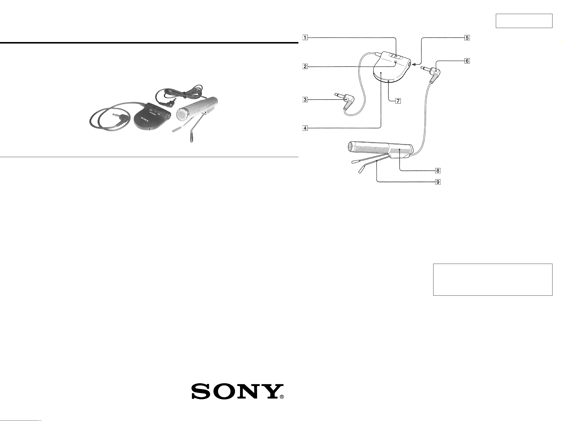
1 POWER switch
2 Battery check indicator
3 L-shaped monaural miniplug (gold plated)
4 Battery box
5 Microphone jack
6 L-shaped monaural miniplug (gold plated)
7 Battery compartment
8 Microphone
9 Attached microphone stand
CAUTION
Danger of explosion if battery is incorrectly replaced.
Replace only with the same or equivalent type recommended by
the manufacturer.
Discard used batteries according to the manufacturer’ s instructions.
ADVARSEL!
Lithiumbatteri-Eksplosionsfare ved fejlagtig håndtering.
Udskiftning må kun ske med batteri
af samme fabrikat og type.
Levér det brugte batteri tilbage til leverandøren.
Notes on chip component replacement
• Never reuse a disconnected chip component.
• Notice that the minus side of a tantalum capacitor may be
damaged by heat.
ELECTRET CONDENSER MICROPHONE
Flexible Circuit Board Repairing
• Keep the temperature of soldering iron around 270˚C
during repairing.
• Do not touch the soldering iron on the same conductor of the
circuit board (within 3 times).
• Be careful not to apply force on the conductor when soldering
or unsoldering.
ADVARSEL
Eksplosjonsfare ved feilaktig skifte av batteri.
Benytt samme batteritype eller en tilsvarende type
anbefalt av apparatfabrikanten.
Brukte batterier kasseres i henhold til fabrikantens
instruksjoner.
VARNING
Explosionsfara vid felaktigt batteribyte.
Använd samma batterityp eller en likvärdig typ som
rekommenderas av apparattillverkaren.
Kassera använt batteri enligt gällande föreskrifter.
VAROITUS
Paristo voi räjähtää, jos se on virheellisesti asennettu.
V aihda paristo ainoastaan laite valmistajan suosittelemaan tyyppiin.
Hävitä käytetty paristo valmistajan ohjeiden mukaisesti.
— 2 —
Page 2

ECM-Z60
SECTION 2
DIAGRAMS
2-1. SCHEMATIC DIAGRAM
UDZ4.7B
2-2. PRINTED WIRING BOARD
12
MIC UNIT
A
B
C
J1
MIC IN
D
34567
UNIT BOARD
(SIDE A)
AMP BOARD
1-671-999-
(MIC OUT)
(SIDE A)
D10
MIC1
MINI
PLUG
11
(11)
UNIT BOARD
(SIDE B)
11
1-671-999-
(11)
AMP BOARD
(SIDE B)
TOTAL CURRENT : 0.21mA
LITHIUM BATTERY
Note on Schematic Diagram:
• All capacitors are in µF unless otherwise noted. pF: µµF
50 WV or less are not indicated except for electrolytics
and tantalums.
• All resistors are in Ω and 1/
specified.
4
W or less unless otherwise
• % : indicates tolerance.
• C : panel designation.
• Signal path.
F : MIC
E
F
G
H
SW1
POWER
ON
OFF
D3
R13
JC1
BATTERY
SW1
D1
R1
C1
16
D2
R3
C2
CHECK
LAMP
(MIC OUT)
C14
1-672-000-
MINI
PLUG
11
(11)
LITHIUM
BATTERY
CR-2025
3V
1-672-000-
11
(11)
• Semiconductor
Location
Ref. No. Location
D1 F-2
D2 F-2
D3 D-2
D10 B-4
— 3 — — 4 —
Note on Printed Wiring Board:
• X : parts extracted from the component side.
a
•
: Through hole.
• b : Pattern from the side which enables seeing.
Caution:
Pattern face side: Parts on the pattern face side seen from
(Conductor B) the pattern face are indicated.
Parts face side: Parts on the parts face side seen from
(Component A) the parts face are indicated.
Page 3

SECTION 3
EXPLODED VIEWS
NOTE:
• -XX, -X mean standardized parts, so they may
have some differences from the original one.
• Items marked “*” are not stocked since they
are seldom required for routine service. Some
delay should be anticipated when ordering these
items.
3-1. BATTERY BOX SECTION
• The mechanical parts with no reference number
in the exploded views are not supplied.
• Aaccessories and packing materials are given
in the last of this parts list.
5
4
2
6
not supplied
3-2. MICROPHONE SECTION
56
53
not supplied
52
7
58
60
55
8
9
MIC1
10
58
54
59
1
11
not supplied
51
#1
#1
Ref. No. Part No. Description Remarks Ref. No. Part No. Description Remarks Ref. No. Part No. Description Remarks Ref. No. Part No. Description Remarks
1 1-790-104-11 CORD,MICROPHONE (1 CORE)
2 2-545-592-01 BUSHING
4 X-2542-165-1 CASE(UPPER) ASSY, BATTERY
5 2-545-588-01 KNOB,SWITCH
* 6 A-4542-610-A AMP BOARD, COMPLETE
8 2-545-590-01 TERMINAL, MINUS
9 2-545-599-01 SHEET, BLIND
10 2-545-586-01 CASE(LOWER), BATTERY
11 2-545-587-01 HOLDER, BATTERY
12 2-545-953-01 LABEL, MODEL NUMBER
12
51 X-2542-196-1 CAPASSY, FRONT
52 2-545-947-01 CAP,REAR
53 2-545-944-01 CASE(R)
54 2-545-943-01 CASE(L)
55 2-545-951-01 FOOT, RUBBER
57 2-545-948-01 HOLDER, STAND
58 2-545-952-01 SCREEN, CASE
59 X-2542-197-1 STAND ASSY
* 60 1-671-999-11 UNIT BOARD
MIC1 1-418-258-11 MICROPHONE UNIT
57
7 2-545-589-01 TERMINAL, PLUS
#1 7-685-103-19 SCREW +P 2X5 TYPE2 NON-SLIT
56 1-791-753-11 CORD, MICROPHONE
— 5 — — 6 —
#1 7-685-103-19 SCREW +P 2X5 TYPE2 NON-SLIT
Page 4

SECTION 4
AMP UNIT
NOTE:
• Due to standardization, replacements in the
parts list may be different from the parts
specified in the diagrams or the components
used on the set.
• -XX, -X mean standardized parts, so they
may have some difference from the original
one.
• Items marked “*” are not stocked since they
are seldom required for routine service.
Some delay should be anticipated when
ordering these items.
Ref. No. Part No. Description Remarks Ref. No. Part No. Description Remarks
* A-4542-610-A AMP BOARD, COMPLETE
********************
ELECTRICAL PARTS LIST
• CAPACITORS:
uF: µF
• RESISTORS
All resistors are in ohms.
METAL: metal-film resistor
METAL OXIDE: Metal Oxide-film resistor
F: nonflammable
• COILS
uH: µH
* 1-671-999-11 UNIT BOARD
• SEMICONDUCTORS
In each case, u: µ, for example:
uA...: µA... , uPA... , µPA... ,
uPB... , µPB... , uPC... , µPC... ,
uPD..., µPD...
When indicating parts by reference number,
please include the board name.
**********
ECM-Z60
< CAPACITOR >
C1 1-119-749-11 CAP, CHIP TANTALUM ELECT 33MF
C2 1-110-569-11 CAP, CHIP TANTALUM ELECT 47MF
C14 1-164-222-11 CAP, CERAMIC 0.22uF (2012)
< DIODE >
D1 8-719-072-95 DIODE 015AZ3.9-X-TPL3
D2 8-719-063-83 LED SML-510MWT86(BATTERY CHECK LAMP)
D3 8-719-056-29 DIODE 015AZ4.7-TPL3
< JACK >
J1 1-764-624-41 JACK (MIC IN)
< JUMPER >
JC1 1-216-864-11 CONDUCTOR, CHIP (1608)
< RESISTOR >
R1 1-216-833-11 RES, CHIP 10K (1608)
R3 1-216-813-11 RES, CHIP 220 (1608)
R13 1-216-827-11 RES, CHIP 3.3K (1608)
< SWITCH >
SW1 1-692-397-21 SWITCH, SLIDE (POWER)
**************************************************************
< DIODE >
D10 8-719-976-96 DIODE DTZ4.7C
**************************************************************
MISCELLANEOUS
**************
1 1-790-104-11 CORD, MICROPHONE (1 CORE)
56 1-791-753-11 CORD, MICROPHONE
MIC1 1-418-258-11 MICROPHONE UNIT
**************************************************************
ACCESSORIES & PACKING MATERIALS
********************************
3-043-185-11 MANUAL, INSTRUCTION
(ENGLISH/FRENCH/SPANISH)
3-043-185-21 MANUAL, INSTRUCTION
(GERMAN,ITALIAN,PORTUGUESE)(AEP.E)
— 7 —
9-927-604-11
Sony Corporation
Personal Audio Division Company
— 8 —
Printed in Japan © 2000.2
2000B1674-1
Published by General Engineering Dept.
 Loading...