

Page 1
4-290-200-01 (2)
Electronic Viewfinder
取扱説明書 JP
Operating Instructions_____ GB
お買い上げいただきありがとうございます。
電気製品は安全のための注意事項を守らないと、
火災や人身事故になることがあります。
この取扱説明書には、事故を防ぐための重要な注意事項と製品の取り扱いかたを示してあります。
この取扱説明書をよくお読みのうえ、製品を安全にお使いください。お読みになったあとは、
いつでも見られるところに必ず保管してください。
DXF-C50WA
© 2011 Sony Corporation
Page 2
日本語
安全のために
電気製品は、安全のための注意事項を守らないと、火災や感電などにより死亡や
大けがなど人身事故につながることがあり、危険です。
事故を防ぐために次のことを必ずお守りください。
安全のための注意事項を守る
3、4 ページの注意事項をよくお読みください。
定期点検をする
長期間安全に使用していただくために、定期点検を実施することをおすすめしま
す。点検の内容や費用については、ソニーのサービス窓口にご相談ください。
故障したら使用を中止する
ソニーのサービス担当者、またはソニーのサービス窓口にご連絡ください。
警告表示の意味
この取扱説明書および製品では、
次のような表示をしています。表
示の内容をよく理解してから本文
をお読みください。
この表示の注意事項を守らないと、
火災や感電などにより死亡や大け
がなど人身事故につながることが
あります。
万一、異常が起きたら
・ 異常な音、におい、煙が出たら
・ 落下させたら
m
a カメラの電源を切る。
b カメラから本製品をはずす。
c ソニーのサービス担当者、またはソニーのサービス窓口に相談する。
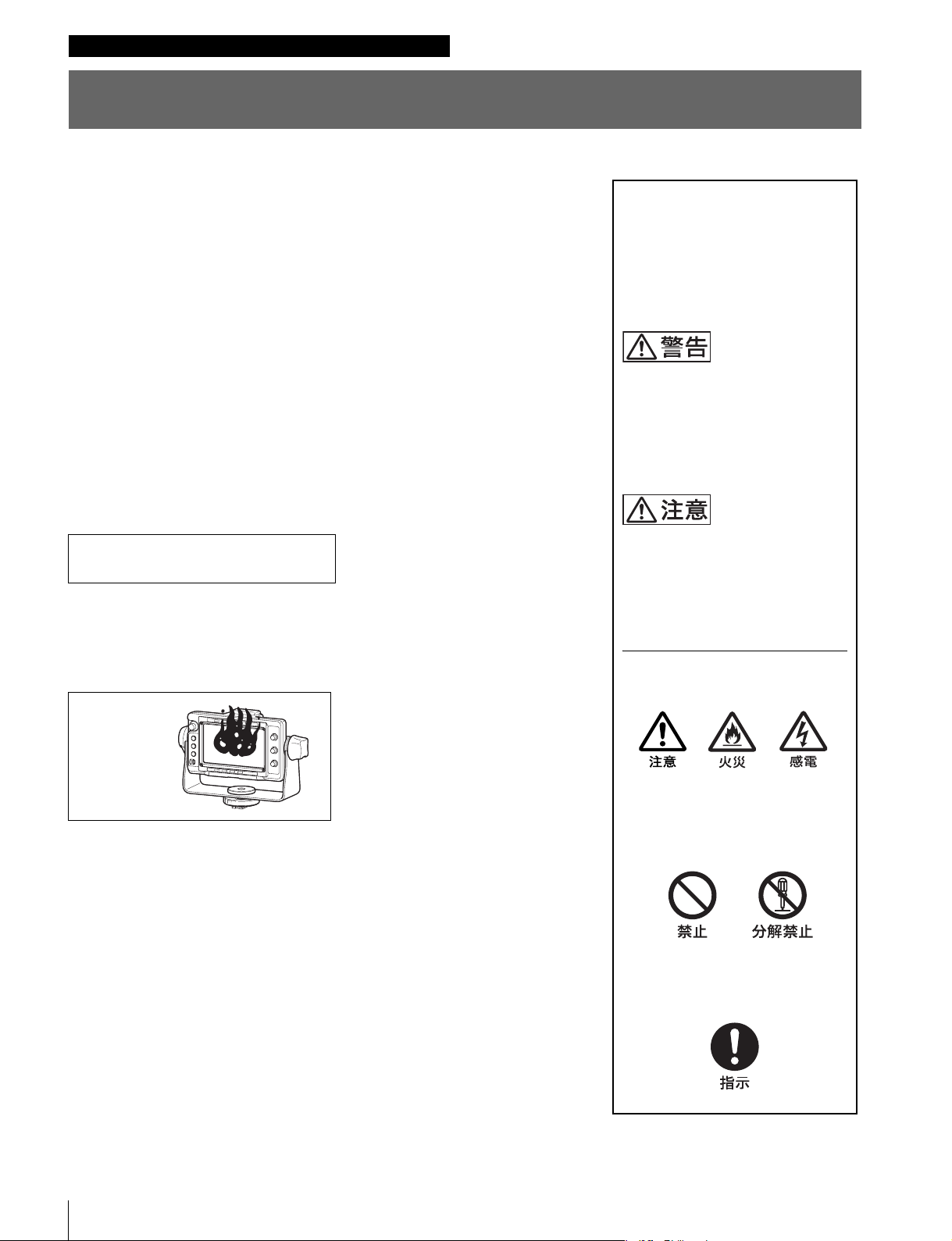
炎が出たら
m
a すぐにカメラの電源を切り、消火する。
この表示の注意事項を守らないと、
感電やその他の事故によりけがを
したり周辺の物品に損害を与えた
りすることがあります。
注意を促す記号
行為を禁止する記号
行為を指示する記号
2
Page 3
目次
告
警告 ...................................................................................3
注意 ...................................................................................4
使用上のご注意 ....................................................................... 4
概要........................................................................................... 5
各部の名称と働き.................................................................... 6
カメラに取り付ける................................................................7
電源を入れる ........................................................................... 8
位置を調整する ....................................................................... 8
パンニング調整.....................................................................................8
チルティング調整...............................................................................9
アクセサリーを取り付ける ....................................................9
フードの取り付け...............................................................................9
ナンバープレートの取り付け................................................. 10
フォーカスアシスト機能を使う .........................................10
ピーキング(PEAKINGPLUS)機能..............................10
拡大表示(MAGNIFICATION)機能.............................12
レベルアジャスト機能を使う .............................................13
メニューを使う .................................................................... 14
メニューモードの基本操作.......................................................14
メニュー一覧.......................................................................................16
エラーメッセージ................................................................. 21
保証書とアフターサービス .................................................21
保証書 .......................................................................................................21
アフターサービス............................................................................21
仕様........................................................................................ 22
分解しない、改造しない
外装を外したり、改造したりすると、感
電の原因となります。
ビューファインダー内部の調整や設定お
よび点検を行う必要がある場合は、必ず
サービストレーニングを受けた技術者に
ご依頼ください。
内部に水や異物を入れない
水や異物が入ると火災や感電の原因とな
ることがあります。
万一、水や異物が入ったときは、すぐに
カメラの電源を切り、カメラから本製品
をはずし、ソニーのサービス担当者また
はソニーのサービス窓口にご相談くださ
い。
油煙、湯気、湿気、ほこりの
多い場所では設置・使用しな
い
上記のような場所で設置・使用すると、
火災や感電の原因となります。
警
JP
目次 / 警告
目次
3
Page 4
ビューファインダーの取り付
け、取りはずしの際は三脚を
チルトロックする
ビューファインダーを取り付け、取りは
ずすときは、三脚のチルトロックを確実
に固定してください。転倒してけがの原
因となることがあります。
画面を動かす際に手指を挟ま
ないように注意する
ビューファインダーの位置を調節すると
きは、手指をはさまないように注意して
ください。
使用上のご注意
• 本機の液晶パネルは有効画素 99.99%以上の非常に精密度
の高い技術で作られていますが、画面上に黒い点が現れ
たり(画素欠け)、常時点灯している輝点(赤、青、緑な
ど)や滅点がある場合があります。また、液晶パネルの
特性上、長期間ご使用の間に画素欠けが生じることもあ
ります。これらの現象は故障ではありませんので、ご了
承の上本機をお使いください。なお、これらの現象はカ
メラの映像出力には影響しません。
• 静止画を継続的に表示すると残像が現れることがありま
す。長時間使用しないときは電源を切ってください。
• 低温でのご使用時には、電源投入直後、動解像度が低下
いたします。
• 画面の表面からほこりを取り除くときは、ブロアーをお
使いください。
• 画面をクリーニングするときは、シンナーなどの溶剤は
いっさい使用しないでください。
スクリーンセーバーについて
• 本機には、焼き付きを軽減するためのスクリーンセー
バー機能が内蔵されています。ほぼ静止した画像を表示
したまま 5 分以上経過すると、自動的にこの機能が働き、
画面の輝度を下げます。
• カメラ画像を変化させたり、本機のステータスを表示さ
せることで解除できます。
注意
4
注意 / 使用上のご注意
Page 5

概要
本体は約 1.2kg と軽量で、堅牢なアルミダイキャストボ
ディを採用しており、重心移動もないため、操作性にすぐ
れています。
エレクトロニックビューファインダー DXF-C50WA は、ソ
ニーカラービデオカメラおよびカムコーダー用の 5 型カ
ラービューファインダーです。
本機には以下のような特長があります。
広視野角特性
5 型 IPS 液晶を採用し、広視野角を実現しています。
フォーカスアシスト機能
独自のフォーカスアシスト機能の搭載により、正確な
フォーカス調整をサポートします。
• 画像拡大表示機能
画枠合わせ用の画像を表示しつつ、画像の一部を拡大表
示します。
• ピーキング・プラス機能
色、表示エリアもしくはその両方で特定した被対象物に
対してのみ輪郭を強調します。
プリセット調整値への切り換え
あらかじめ調整しておいた明るさ、コントラスト、ピーキ
ング、クロマレベルの設定を、アサイナブルスイッチ操作
またはメニュー操作により切り換えられます。
スタジオ用屋内フード(付属)および OB
用屋外フード VFH-570(別売)を取り付
け可能
付属のスタジオ用屋内フードと、遮光性に優れている別売
の OB 用屋外フード(VFH-570)を用意しています。
アサイナブルスイッチ
機能を任意に割り当てることができるスイッチのことで、2
つ搭載しています。
タリーランプ
タリー信号によって点灯する 2 系統(レッド、グリーン)
のタリーランプを備えています。
波形モニター表示機能
入力信号の波形(ウェーブフォーム)を子画面で簡易表示
できます。
ガイドフレーム表示機能
水平/垂直のライン合わせの目安となるマーカーを表示で
きます。
優れた操作性
パンニングは左右方向にそれぞれ 90°、チルティングは上
に 90°、下に 60°の範囲で調整できます。
概要
5
Page 6
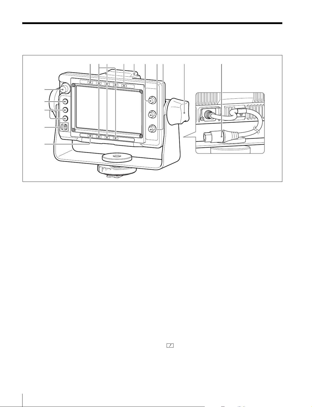
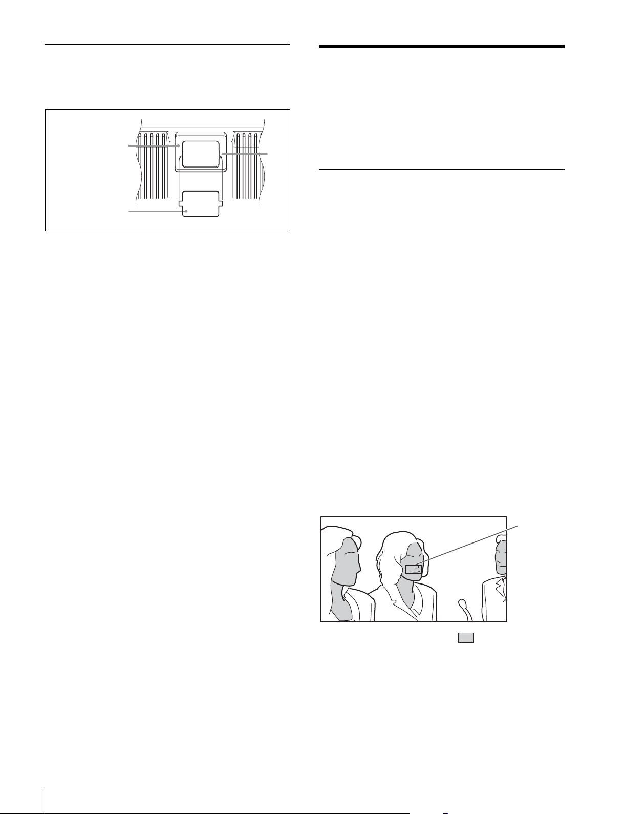
各部の名称と働き
231 4 56 7 8 9 0
qg
qf
qd
qs
qa
a MAG(拡大表示)インジケーター
画像を拡大表示しているとき(MAGNIFICATION 機能を
割り当てた ASSIGN. スイッチを ON にしたとき、または
MAGNIFICATION メニューの「MAGNIFICATION」を
「ON」にしたとき)、点灯します。
b RTALLY インジケーター(赤)
レッドタリー信号が入力されると、点灯します。
c GTALLY インジケーター(緑)
グリーンタリー信号が入力されると、点灯します。
d BATT(バッテリー)インジケーター
点灯または点滅して、カメラに接続したバッテリーの状態
を示します。
点灯:バッテリー消耗
点滅:バッテリーの電圧低下
カメラの動作中断を防ぐため、このインジケーターが点滅
を開始したらすみやかにバッテリーを交換してください。
◆ 点滅を開始する電圧を、カメラ側で設定することができます。
詳しくは、使用しているカメラの取扱説明書をご覧ください。
「ON」にしたとき、RTALLY インジケーターと同様に
レッドタリー信号が入力されると、点灯します。
f BRIGHT つまみ
画像の明るさを調整します。
g CONTRAST つまみ
画像のコントラスト(濃淡)を調整します。
h PEAKING つまみ
画像の輪郭を調整します。
時計方向に回すと画像の輪郭が強調されます。
1)
これらのつまみによる調整は、カメラの出力信号には影響あり
ません。
i チルティングロックつまみ
チルティングポジションを任意の位置でロックできます。
j 接続コネクター
カメラの VF コネクターと接続します。
カメラから電源、映像信号、タリー信号が入力されます。
1)
1)
1)
e アップタリーランプ(赤)
ナンバープレート(付属)が取り付け可能です。
UPTALLY を割り当てた ASSIGN. スイッチを ON にした
とき、または TALLY/IND メニューの「UPTALLY」を
各部の名称と働き
6
k (注意)インジケーター(アンバー)
カメラのシャッタースイッチを ON にしたとき、または
GAIN が 3dB 以上のとき、点灯します。
Page 7
◆ 使用するカメラによっては、 インジケーターが点灯する条件
をカメラ側で設定できる場合があります。詳しくは、使用して
いるカメラの取扱説明書をご覧ください。
l POWER(電源)スイッチ
SAVE にすると LCD 部の電源がオフになり、省電力状態
になります。
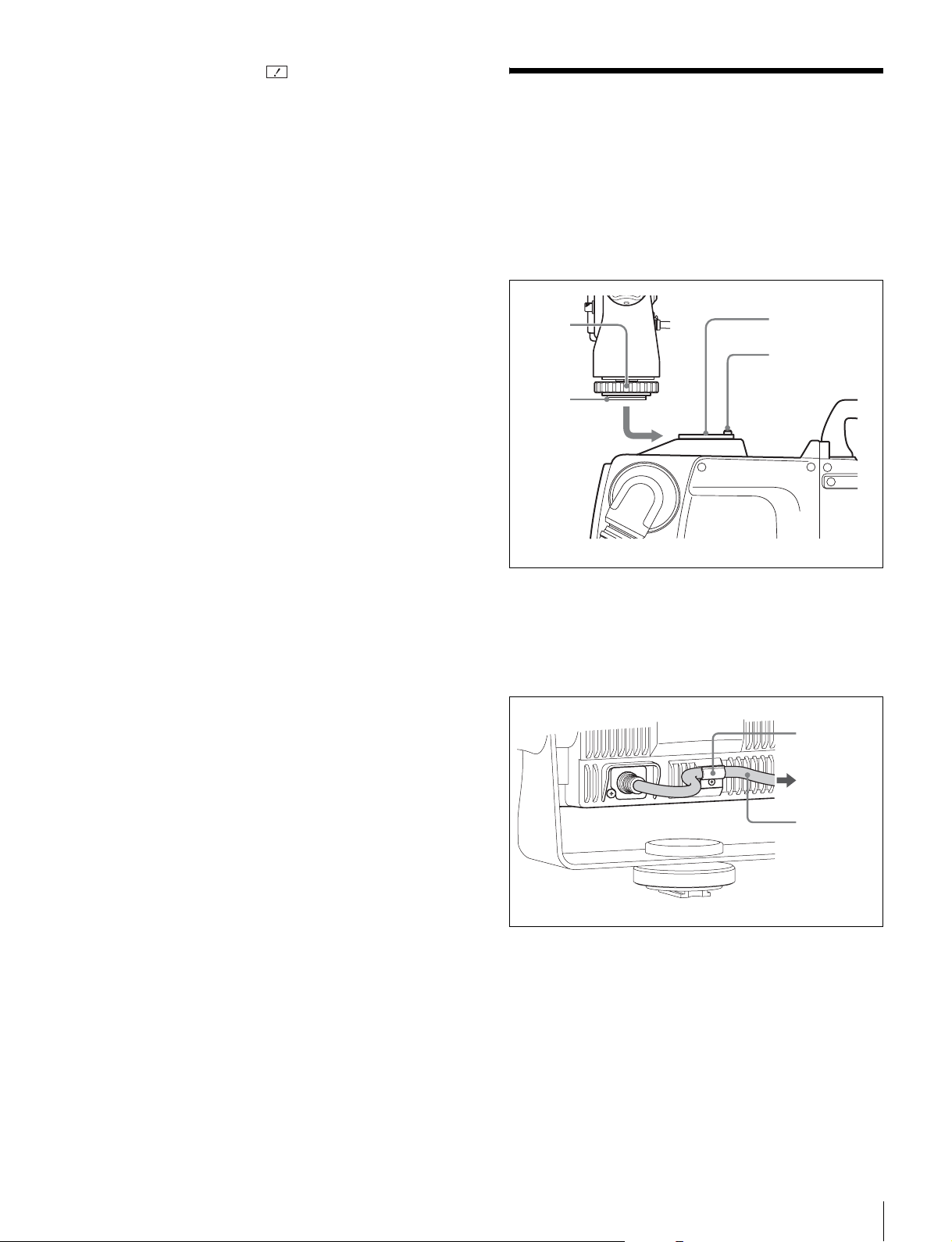
カメラに取り付ける
1
ガイド板がストッパーにあたって止まるまで、カメラ
のアクセサリーシューにガイド板をはめこむ。
m ASSIGN.(アサイナブル)スイッチ
よく使う機能を任意で割り当てることができます。
上側が ASSIGN.1 スイッチ、下側が ASSIGN.2 スイッチで
す。
機能の割り当ては FUNCTION メニューの「ASSIGN.1」、
「ASSIGN.2」で設定します。
n MENU(メニュー)スイッチ
メニューを表示します。MENUSEL つまみと併用して、さ
まざまな機能の設定をします。
メニューが表示されていないときに 3 秒以上押すと「VR
LOCK」が表示され、BRIGHT、CONTRAST、PEAKING
つまみをロックして、誤操作を防ぐことができます。もう
一度 3 秒以上押すと「VRUNLOCK」が表示され、ロック
が解除されます。
◆ 操作方法については、「メニューを使う」(14 ページ)をご覧く
ださい。
o MENUSEL(メニュー選択)つまみ
つまみを回してメニュー項目を選択し、つまみを押して確
定します。MENU スイッチと併用して、さまざまな機能の
設定をします。
メニューが表示されていないときは、押している間、画面
に本機のステータス情報を表示します。
◆ 操作方法については、「メニューを使う」(14 ページ)をご覧く
ださい。
2
固定リングを締め、ビューファインダーをしっかりと
固定する。
固定
リング
ガイド板
3
本機の接続コネクターとカメラの VF コネクターとを接
続する。
接続ケーブルは、下図のようにクランプで固定してく
ださい。
カメラの
アクセサリー
シュー
ストッパー
クランプ
カメラの VF
コネクターへ
接続
ケーブル
取りはずすには
固定リングを緩め、差し込んだ側とは逆方向に本機を引い
て取りはずします。
カメラに取り付ける
7
Page 8
電源を入れる
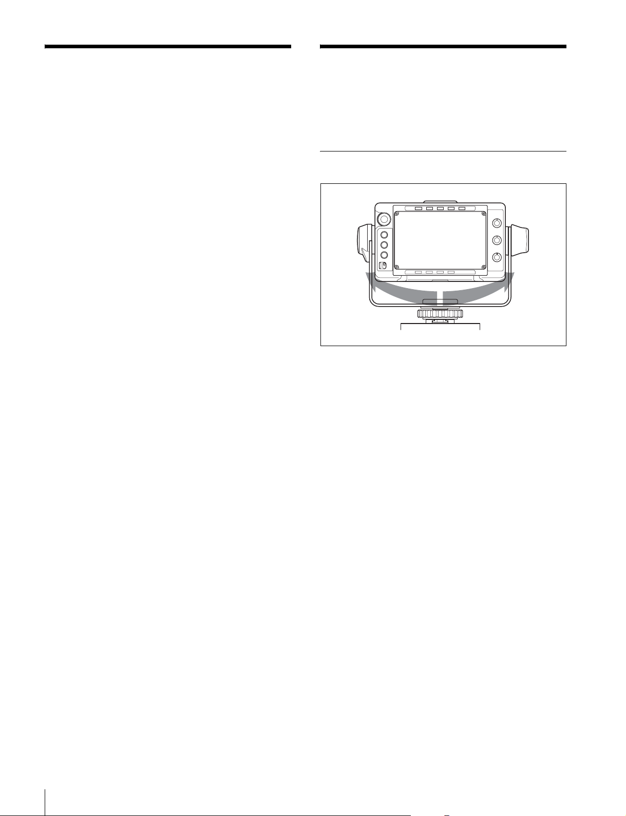
位置を調整する
カメラの電源を入れ、本機の POWER スイッチを ON にす
ると電源が入ります。
電源が入ると数秒後に、画像が表示されます。
ビューファインダーの位置を以下のように調整して、お使
いください。
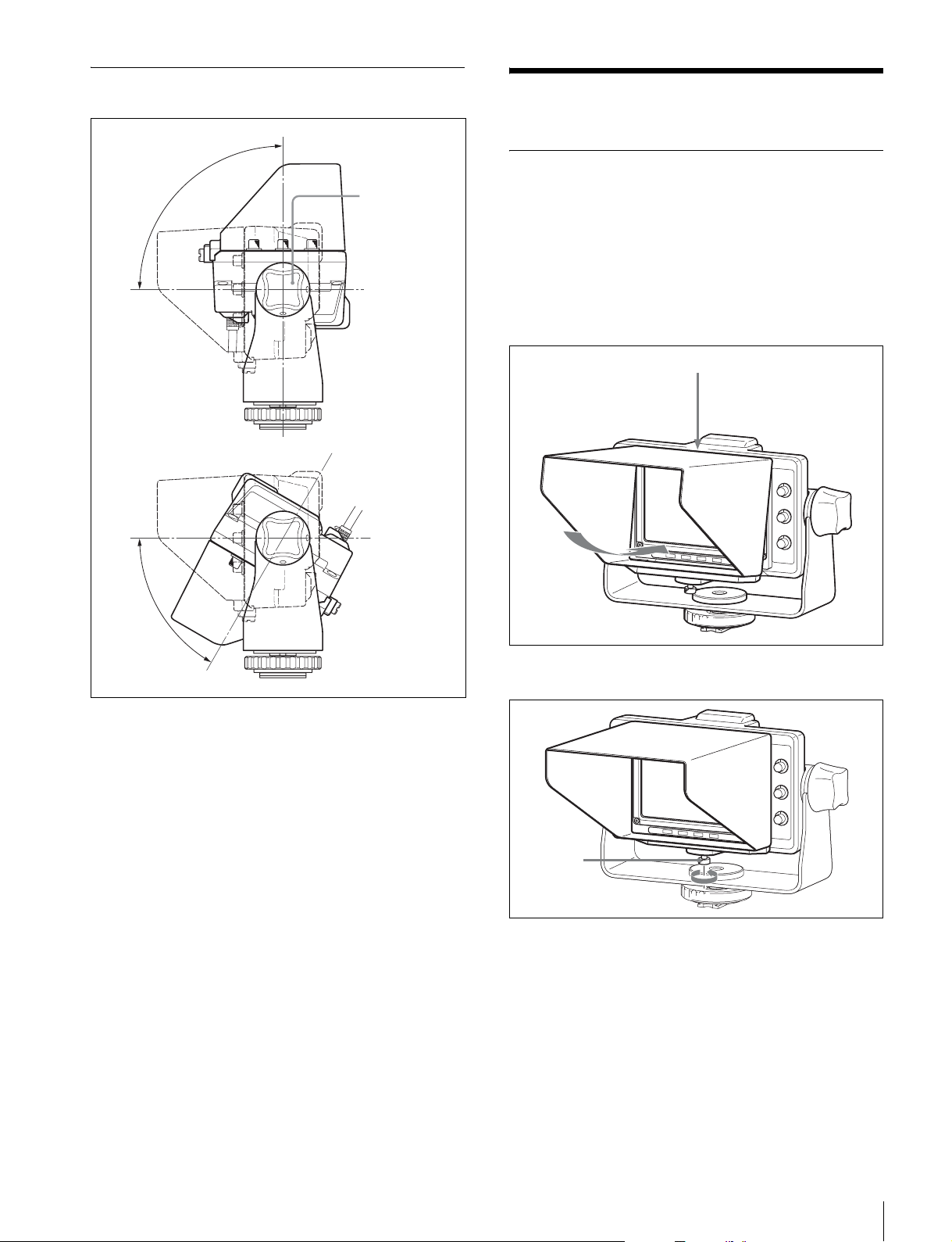
パンニング調整
180°
正面をセンターとして左右に 90°ずつ動かすことができま
す。
電源を入れる/位置を調整する
8
Page 9
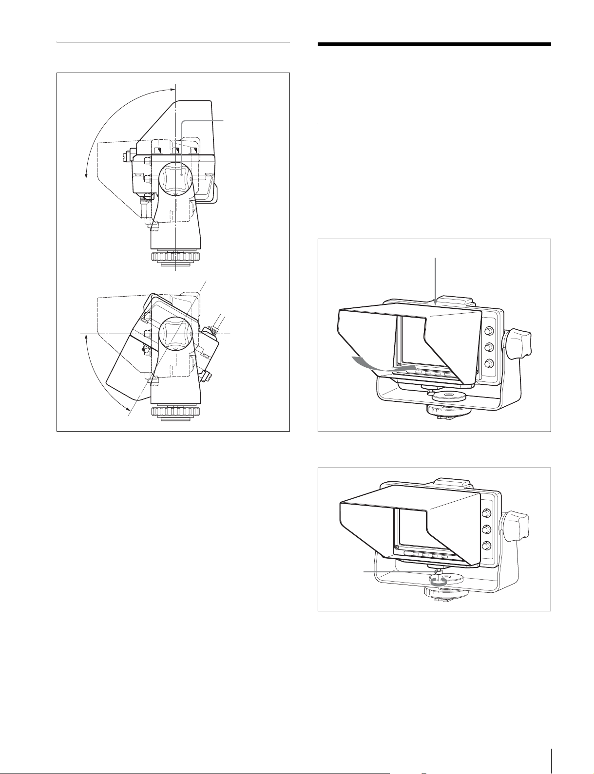
チルティング調整
アクセサリーを取り付け
る
90°
60°
チルティング
ロックつまみ
(右回しでロッ
ク)
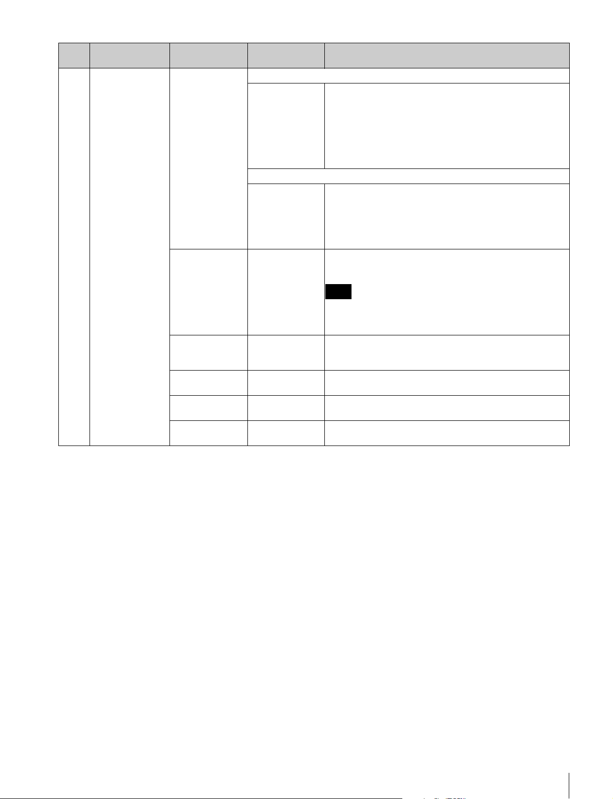
フードの取り付け
OB 用屋外フード VFH-570(別売)の取り付けかたは、ス
タジオ用モニターフード(付属)と同じです。
ここでは、スタジオ用モニターフード(付属)の取り付け
かたとして説明します。
1
溝に引っかけて、取り付ける。
溝
1
チルティングロックつまみを左に回してロックを解除
する。
2
チルティング角度を調整する。
3
チルティングロックつまみを右に回して固定する。
2
ネジを回して、固定する。
ネジ
アクセサリーを取り付ける
9
Page 10
ナンバープレートの取り付け
ナンバープレート(付属)の左右のつめをアップタリーラ
ンプの溝に差し込みます。
アップタリーランプ
溝
フォーカスアシスト機能
を使う
◆ メニューの操作方法については、「メニューを使う」(14 ペー
ジ)をご覧ください。
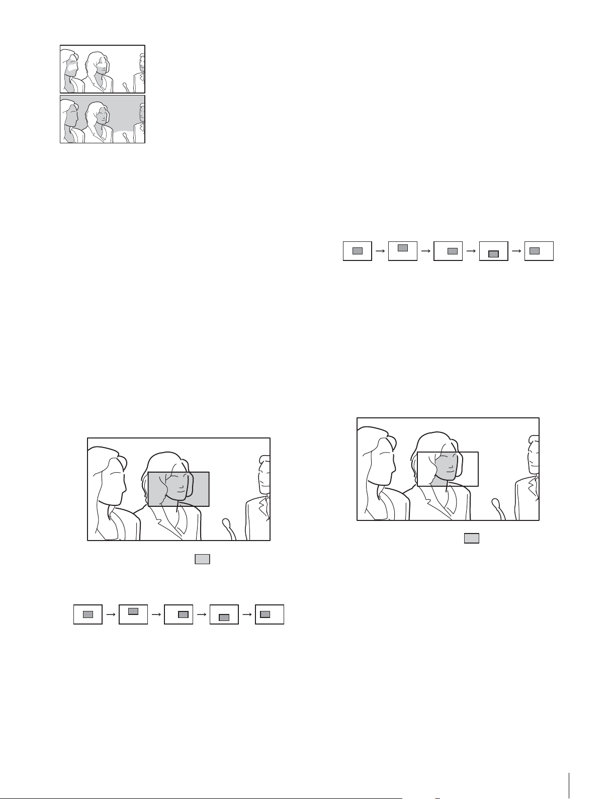
ピーキング(PEAKINGPLUS)機
ナンバープレート
1
能
色または表示エリア、あるいはその両方で特定した画像の
輪郭を補正できます。通常どおり、画像全体に対して輪郭
補正をかけることもできます。カメラの映像出力には影響
しません。
色で特定した画像の輪郭を補正するには
1
PEAKINGPLUS機能を割り当てたASSIGN.スイッチを
押して、PEAKINGPLUS モードに切り換える。
PEAKING メニューの「PEAKINGMODE」でも設定
できます(17 ページ)。
2
PEAKING メニューの「COLOR/AREASEL」で
「COLOR」を選択する。
3
PEAKINGPLUS機能を割り当てたASSIGN.スイッチを
1 秒以上押したまま(画面中央部に検出エリアマー
カーが表示される)、補正したい色に検出エリアマー
カーを合わせてスイッチを離す。
補正したい色が検出されます。
フォーカスアシスト機能を使う
10
検出エリア
マーカー
:輪郭補正有効エリア
4
PEAKING メニューの以下のメニューで、輪郭補正する
色の有効範囲を調整する。
• HUEPHASE:色相の中心位相
• HUEWIDTH:色相の範囲
• SATWIDTH:彩度の範囲
Page 11
−方向:有効範囲が狭くなる
色と表示エリアの両方で指定するには
1
PEAKINGPLUS機能を割り当てたASSIGN.スイッチを
押して、PEAKINGPLUS モードに切り換える。
+方向:有効範囲が広くなる
5
PEAKING つまみで補正量を調節する。
手順 3 で検出された色と一致した被写体の輪郭のみ補
正されます。
時計回りに回すと輪郭がはっきりします。
表示エリアで特定した画像の輪郭を補正す
るには
1
PEAKINGPLUS機能を割り当てたASSIGN.スイッチを
押して、PEAKINGPLUS モードに切り換える。
PEAKING メニューの「PEAKINGMODE」でも設定
できます(17 ページ)。
2
PEAKING メニューの「COLOR/AREASEL」で
「AREA」を選択する。
3
PEAKING メニューの「POSITION」でエリアを選択す
る。
PEAKING メニューの「PEAKINGMODE」でも設定
できます(17 ページ)。
2
PEAKING メニューの「COLOR/AREASEL」で
「BOTH」を選択する。
3
PEAKING メニューの「POSITION」でエリアを選択す
る。
CNT UPPER LOWERRIGHT LEFT
「POSITION」の設定を変更すると、MAGNIFICATION
メニューの「MAGPOSITION」の設定も連動して変更
されます。
4
PEAKINGPLUS機能を割り当てたASSIGN.スイッチを
1 秒以上押したまま(画面中央部に検出エリアマー
カーが表示される)、補正したい色に検出エリアマー
カーを合わせてスイッチを離す。
補正したい色が検出されます。
:輪郭補正有効エリア
CNT UPPER LOWERRIGHT LEFT
「POSITION」の設定を変更すると、MAGNIFICATION
メニューの「MAGPOSITION」の設定も連動して変更
されます。
4
PEAKING つまみで補正量を調節する。
手順 3 で選択したエリア内のみ補正されます。
時計回りに回すと輪郭がはっきりします。
:輪郭補正有効エリア
5
PEAKING メニューの以下のメニューで、輪郭補正する
色の有効範囲を調整する。
• HUEPHASE:色相の中心位相
• HUEWIDTH:色相の範囲
• SATWIDTH:彩度の範囲
6
PEAKINGつまみで補正量を調節する。
手順 4 で検出された色と一致した被写体の輪郭が、
手順 3 で選択したエリア内のみ補正されます。
時計回りに回すと輪郭がはっきりします。
フォーカスアシスト機能を使う
11
Page 12
画像全体に対して輪郭補正をかけるには
1
PEAKINGPLUS機能を割り当てたASSIGN.スイッチを
押して、STD(通常)モードに切り換える。
PEAKING メニューの「PEAKINGMODE」でも設定
できます(17 ページ)。
2
PEAKING つまみで補正量を調節する。
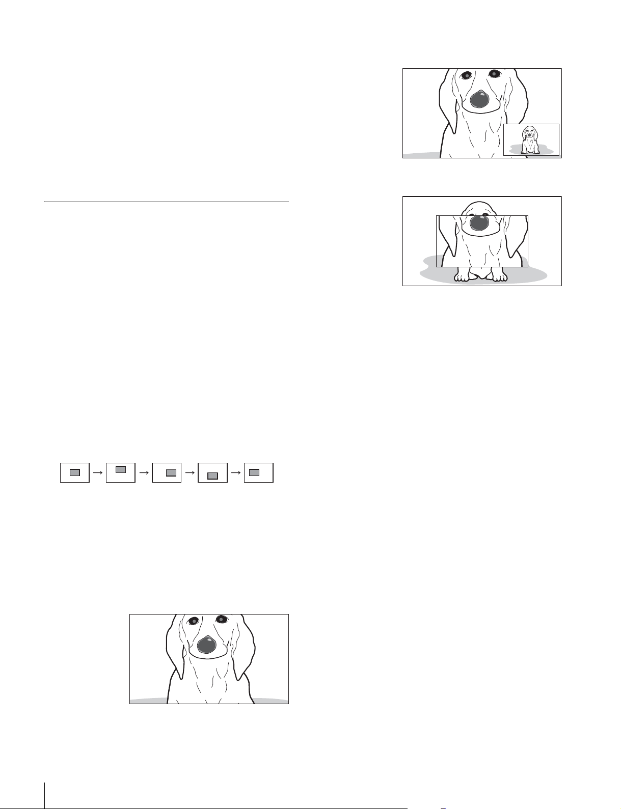
MODE2:拡大表示内の右下に元画像を表示
時計回りに回すと輪郭がはっきりします。
拡大表示(MAGNIFICATION)機能
構図合わせ用とフォーカス合わせ用の画像を同時に表示で
きます。
1
MAGNIFICATION機能を割り当てたASSIGN.スイッチ
を押す。
画像が拡大表示されます。
MAGNIFICATION メニューでも設定できます(17
ページ)。
2
MAGNIFICATION機能を割り当てたASSIGN.スイッチ
を押したままにする。
拡大部分が以下の順で切り換わります。
「MAGNIFICATION」メニューの「MAGPOSITION」
でも設定できます(17 ページ)。
CNT UPPER LOWERRIGHT LEFT
MODE3:元画像表示の中央に拡大画像を表示
通常表示に戻すには
MAGNIFICATION メニューの「AUTORELEASE」の設
定により、次のようになります。
「AUTO」のとき:ASSIGN. スイッチを押して拡大表示し
てから約 5 秒後に、自動で通常表示に戻ります。
「MAN」のとき:もう一度 ASSIGN. スイッチを押すと、通
常表示に戻ります。
「MAGPOSITION」の設定を変更すると、PEAKING メ
ニューの「POSITION」の設定も連動して変更されま
す。
3
MAGNIFICATION メニューの「MODESEL」で表示
MODE1 〜 3 を選択する。
MODE1:通常の拡大表示
フォーカスアシスト機能を使う
12
Page 13

5
「YES」を選択する。
レベルアジャスト機能を
使う
◆ メニューの操作方法については、「メニューを使う」(14 ペー
ジ)をご覧ください。
カメラの出力レベルを本機内部で補正して表示できます。
ご注意
• カメラの出力レベルを調整するものではありません。カ
メラの出力信号には影響しません。
•「AUTOSETUP」を実行する前に、カメラのキャラク
ターおよびマーカーを表示しない状態にしてください。
1
カメラの内蔵カラーバー信号を本機に入力する。
本機は以下のカラーバーに対応しています。
• 75% フルフィールドカラーバー
• 100-75% フルフィールドカラーバー
• 100% フルフィールドカラーバー
• SMPTE カラーバー
• マルチフォーマットカラーバー
補正が実行されます。補正をやめる場合は「NO」を選
択します。
補正が終了すると「COMPLETE」と表示されます。
正しく補正できなかったときは「ERROR」と表示され
ます。その場合はカメラからの内蔵カラーバーを正し
く入力し直し、手順 3 から再び行ってください。
◆ カメラの内蔵カラーバーについては、カメラの取扱説明書
をご覧ください。
2
LEVELADJUST メニューの「COLORBARS」で入力
するカラーバーを選択する。
「AUTO」を選択すると、入力されたカラーバーの種類
を本機が自動的に認識します。
入力するカラーバーを手動で設定するには、以下のい
ずれかを選択します。
7575:75% フルフィールドカラーバー
10075:100-75% フルフィールドカラーバー
100:100% フルフィールドカラーバー
SMPTE:SMPTE カラーバー
MULTI:マルチフォーマットカラーバー
3
LEVELADJUST メニューの「AUTOADJUST」で
「AUTO」を選択する。
自動で調整せず、プリセットされた調整値を使用する
こともできます。詳しくは LEVELADJUST メニュー
の「AUTOADJUST」(20 ページ)をご覧ください。
4
LEVELADJUST メニューの「AUTOSETUP」で
「EXEC」を選択する。
レベルアジャスト機能を使う
13
Page 14
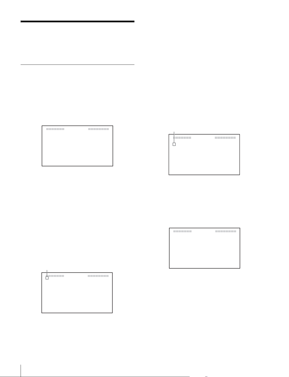
メニューを使う
本機では、メニューを使って操作全般の設定を行います。
メニューモードの基本操作
1
メニューモードに入る。
MENU スイッチを押す。
• ページを選びなおすときは、MENU スイッチを押す
と、ページ選択モードに戻ります。
• 設定値に ? マークがある場合(設定値変更モード)
は、MENU スイッチを押すと項目選択モードに戻り
ます。もう一度 MENU スイッチを押すと、ページ選
択モードになります。
3
項目を選ぶ。
選択したページの設定項目に
c マークが表示されてい
る状態(項目選択モード)で、MENUSEL つまみを回
して、 c マークを移動する。
メニュー画面がビューファインダー画面に表示されま
す。
VF MENUV
?
01 FUNCTION
ASS I GN 1
ASS I GN..2
KN EE
MON C HROM EO
CHR MAO:0
PEA I NG PL US SWK:EDOM1
FMENU
:
MONO
:
MAG
:
FOF
:
FOF
ビューファインダーの画面上にカメラからの映像やメ
ニューが表示されている状態でも、本機のメニューを表
示することができます。このとき、カメラからの映像
やメニュー表示は暗くなり、本機のメニューの背面に
薄く表示されます。
2
メニューページを選ぶ。
ページ番号の前に?マークが表示されている状態
(ページ選択モード)で、MENUSEL つまみを回す。
ページが移動します。
時計方向に回すと、 c マークが下へ移動し、反時計方
向に回すと
項目選択モード
設定したい項目に
c マークが上へ移動します。
c マーク
0MAGNIFICATION
MAGN I F I CA
c
MOD E
MAG
DISPLAY POSI TION
AUTO REL EASE
VF MENU
4
SEL
POS I ITON
TION
c マークを合わせ、MENUSEL つ
:
FOF
:
EDOM1
:
CNT
:
HGIRT
:
TUAO
まみを押す。
設定値に ? マークが表示され、設定画面(設定値変更
モード)になります。
設定値変更モード
V
0MAGNIFICATION4
MAGN I F I CA
MOD E
MAG
DISPLAY POSI TION
AUTO REL EASE
FMENU
TION
SEL
POS I ITON
:
FOF
:
EDOM1
?
:
CNT
:
HGIRT
:
TUAO
14
ページ選択モード
?マーク
0?MAGNIFICATION
MAG
MOD E S E L
MAG
DISPLAY POSI TION
AUTO REL EASE
VF MENU
NIF ICAT ION
POS I ITON
:
FOF
:
:
:
:
14EDOM
CNT
HGIRT
TUAO
希望のページを表示させ、MENUSEL つまみを押す。
選択したページの設定項目に
c マークが表示されます
(項目選択モード)。
メニューを使う
設定項目を選びなおすときは、MENU スイッチを押す
と、項目選択モードに戻ります。
4
設定値を変更する。
設定値に ? マークが表示されている状態(設定値変更
モード)で、MENUSEL つまみを回して、設定値を変
更する。
設定値が数字の場合、MENUSEL つまみを時計方向に
回すと数値が大きくなり、反時計方向に回すと数値が小
さくなります。
Page 15

速く回すと数値が速く変化し、ゆっくり回すと微調整
ができます。
5
設定値を確定する。
MENUSEL つまみを押す。
設定値が確定され、項目選択モードに移ります。
MENUSEL つまみを押す前に、MENU スイッチを押
すと、設定値は変更前の値に戻り、項目選択モードに
戻ります。
6
続けて設定を変更する。
続けて他の設定項目を変更するには、手順 2 〜 5 を繰り
返す。
7
メニューモードから抜ける。
メニュー画面が消えるまで、MENU スイッチを繰り返
し押す。
設定値を工場出荷値に戻すには
戻したい設定項目に?マークが表示されている状態で、
MENUSEL つまみを 2 秒以上押します。
メニューを使う
15
Page 16

メニュー一覧
ご注意
• 選択できない項目は、設定値に「−−−」と表示されま
す。
• 項目によっては、前のメニュー項目で「ON」が選択され
ていないと選択できないものがあります。
ページ メニュー 項目 設定値([ ] は工場出荷値)機能
01 FUNCTION ASSIGN.1 KNEE/PRST/[MONO]/
MAG/UPTLY/PEAK+/
GUIDE/WFM
ASSIGN.2 KNEE/PRST/MONO/
[MAG]/UPTLY/
PEAK+/GUIDE/WFM
KNEE [OFF]/ON KNEE 補正回路の ON/OFF を切り換えます。
MONOCHROME [OFF]/ON カラー表示(OFF)と白黒表示(ON)を切り換えます。
CHROMA − 99 〜 [0] 〜 99 クロマレベルを設定します。
PEAKINGPLUSSW[MODE1]/MODE2 アサイナブルスイッチを押した際の動作モードを切り換えます。
02 TALLY/IND UPTALLY OFF/[ON] アップタリーをコントロールします。
UPTALLYDIM 1 〜 [5] 〜 10 アップタリーランプの光量を設定します。
TALLY/IND OFF/[ON] タリーランプおよびインジケーターをすべて有効にする(ON)か、
TALLY/INDDIM 1 〜 [5] 〜 10 タリーランプやインジケーターの光量を設定します。
ASSIGN.1 スイッチに機能を割り当てます。
各機能の詳細設定はそれぞれのメニューページで設定します。
KNEE:KNEE 補正回路の ON/OFF を切り換える
PRST:PRESET の ON/OFF を切り換える(19 ページの
PRESET メニューを参照)
MONO:白黒表示の ON/OFF を切り換える
MAG:拡大表示機能の ON/OFF を切り換える(1 秒以上押すと
拡大位置を切り換える)
UPTLY:UPTALLY の ON/OFF を切り換える
PEAK+:ピーキング・モードの STD/PLUS を切り換える(1 秒
以上押すと COLORDETECT を実行する)
GUIDE:GUIDEFRAME の ON/OFF を切り換える
WFM:WAVEFORM の ON/OFF を切り換える
ASSIGN.2 スイッチに機能を割り当てます。
各機能は ASSING.1 スイッチと同じです。
数値を小さくするとクロマ量が少なくなります。
MODE1:PEAKINGMODE を STD ⇔ PLUS に切り換える
MODE2:STD → COLOR → AREA → BOTH → STD の順に切
り換える
ON:アップタリーランプが機能する
OFF:アップタリーランプが機能しない(レッドタリー信号がカ
メラから供給されても点灯しない)
数字を大きくすると明るくなり、小さくすると暗くなります。
BATT インジケーター以外をすべて無効にする(OFF)かを切り
換えます。
数字を大きくすると明るくなり、小さくすると暗くなります。
16
メニューを使う
Page 17

ページ メニュー 項目 設定値([ ] は工場出荷値)機能
03 PEAKING PEAKINGMODE [STD]/PLUS ピーキングのモードを切り換えます。
STD:通常モード
PLUS:PEAKINGPLUS モード
COLOR/AREA
SEL
POSITION
PEAKINGUP [OFF]/ON 「PEAKINGMODE」で「PLUS」が選択されているときにピーキ
COLORDETECT EXEC 輪郭強調の対象となる色の検出を行います。
HUEPHASE [0] 〜 359 輪郭強調の対象となる色相の中心位相を設定します。
HUEWIDTH − 99 〜 [0] 〜 99 輪郭強調の対象となる色相の範囲を設定します。
SATWIDTH − 99 〜 [0] 〜 99 輪郭強調の対象となる彩度の範囲を設定します。
FREQUENCY L/[M]/MH/H 輪郭強調信号の中心周波数を設定します。
RANGE 1 〜 [2] 〜 3 輪郭強調のレベルの可変量を設定します。
04 MAGNIFICATION MAGNIFICATION [OFF]/ON 通常表示(OFF)と拡大表示(ON)を切り換えます。
MODESEL [MODE1]/MODE2/
a)
[COLOR]/AREA/BOTH ピーキング・プラスのモードを選択します。
COLOR:選択された色にのみ輪郭強調をかける
AREA:選択された領域にのみ輪郭強調をかける
BOTH:選択された色かつ領域にのみ輪郭強調をかける
[CNT]/UPPER/RIGHT/
LOWER/LEFT
MODE3
「COLOR/AREASEL」で「AREA」または「BOTH」が選択され
ているとき、PEAKING の有効エリアを選択します。
設定値は MAGNIFICATION メニューの「MAGPOSITION」と連
動します。
CNT:中央部が輪郭強調される
UPPER:上部が輪郭強調される
RIGHT:右部が輪郭強調される
LOWER:下部が輪郭強調される
LEFT:左部が輪郭強調される
ング量を +6dB 増やすかどうか選択します。
OFF:RANGE 設定値
ON:RANGE 設定値 +6dB
COLOR または BOTH が選択されているときのみ機能します。
電源投入時は通常表示(OFF)になります。
拡大表示モードを切り換えます。
MAGPOSITION [CNT]/UPPER/RIGHT/
LOWER/LEFT
DISPLAY
POSITION
AUTORELEASE [AUTO]/MAN 拡大表示時、拡大表示から通常表示へ戻す方法を設定します。
LEFT/[RIGHT] 拡大表示画面(子画面)の位置を切り換えます。
拡大表示時、拡大表示する部分を選択します。
設定値は PEAKING メニューの「POSITION」と連動します。
CNT:中央部が拡大して表示される
UPPER:上部が拡大して表示される
RIGHT:右部が拡大して表示される
LOWER:下部が拡大して表示される
LEFT:左部が拡大して表示される
LEFT:画面左下に子画面が表示される
RIGHT:画面右下に子画面が表示される
AUTO:ASSIGN.1 または ASSIGN.2 スイッチを押して拡大表示
してから約 5 秒後に、自動的に通常表示に戻る
MAN:ASSIGN.1 または ASSIGN.2 スイッチを押して拡大表示し
てからもう一度押すと、通常表示に戻る
メニューを使う
17
Page 18

ページ メニュー 項目 設定値([ ] は工場出荷値)機能
05 GUIDEFRAME 水平/垂直のライン合わせの目安となるガイ
ドフレームを表示します。右図は、
「PATTERNSEL」で「3X3」を選択した場合
のガイドフレーム表示例です。
GUIDEFRAME [OFF]/ON 通常表示(OFF)とガイドフレーム表示(ON)を切り換えます。
PATTERNSEL [3X3]/5X5/9X9 ガイドフレームのセル表示パターンを選択します。
COLOR [W]/R/G/B/YL ガイドフレームの表示色を選択します。
LEVEL 1 〜 [5] 〜 10 ガイドフレームの表示レベルを設定します。数値を大きくすると明
るくなります。
06 WAVEFORM 入力信号の波形(ウェーブフォーム)を子画
面で簡易表示します。右図は、画像がカラー
バーのときの波形モニターの例です。
ご注意
• WAVEFORM メニュー(波形モニター表
示)を使用するときは、事前に必ず
LEVELADJUST メニューでカメラの出力
レベルを調整してください。
• 波形モニターは簡易表示なので目安として
お使いください。
選択ライン
カーソル
波形
WAVEFORM [OFF]/ON 通常表示(OFF)と波形モニター表示(ON)を切り換えます。
INTENSITY 1 〜 [5] 〜 10 波形モニター表示の明るさを設定します。数値を大きくすると明る
くなります。
POSITION LEFT/[RIGHT] 波形モニターの表示位置を切り換えます。
LEFT:画面左下に表示される
RIGHT:画面右下に表示される
LEFT RIGHT
HALFTONE [OFF]/ON 波形モニターの背景を黒色にするか(OFF)、背景を透かしたハー
フトーン表示にするか(ON)を選択します。
SWEEP [LINE]/FIELD 波形モニターの表示モードを切り換えます。
LINE:横軸を 1H として、レベルが表示される
FIELD:横軸を 1V として、レベルが表示される
LINESELECT [OFF]/ON 「SWEEP」で「LINE」が選択されているときに、通常画面にするか
(OFF)、選択ラインのレベルを表示するか(ON)を選択します。
LINE 0 〜 [50] 〜 100 選択ライン表示時、選択ラインの位置を設定します。
数値を大きくすると下方向、小さくすると上方向に移動します。
COLOR [W]/R/G/B/YL 選択ライン表示時、選択ラインの表示色を選択します。
INTENSITY 1 〜 [5] 〜 10 選択ラインの明るさを設定します。数値を大きくすると明るくなり
ます。
CURSOR 0 〜 [50] 〜 100 波形モニター内に表示されるカーソルの位置を設定します。数値を
大きくすると上方向、小さくすると下方向に移動します。
COLOR [W]/R/G/B/YL カーソルの表示色を選択します。
18
メニューを使う
Page 19

ページ メニュー 項目 設定値([ ] は工場出荷値)機能
07 PRESET PRESET [OFF]/ON BRIGHT、CONTRAST、PEAKING の各つまみおよび
FUNCTION メニューで設定されたクロマレベルと、PRESET メ
ニューの「PRSTBRIGHT」、「PRSTCONTRAST」、「PRST
PEAKING」、「PRSTCHROMA」で設定されたプリセット値のど
ちらを有効にするかを切り換えます。
OFF:つまみおよび FUNCTION メニューで設定されたクロマレ
ベルが有効
ON:PRESET メニューの設定値が有効
PRSTBRIGHT − 99 〜 [0] 〜 99 「PRESET」で「ON」が選択されているときに画像の明るさを設定
します。
数値を大きくすると画像が明るくなります。
PRSTCONTRAST − 99 〜 [0] 〜 99 「PRESET」で「ON」が選択されているときに画像のコントラスト
を設定します。
数値を大きくするとコントラストが強くなります。
PRSTPEAKING [0] 〜 100 「PRESET」で「ON」が選択されているときにピーキング量を設定
します。
数値を大きくすると補正量が多くなります。
PRSTCHROMA − 99 〜 [0] 〜 99 「PRESET」で「ON」が選択されているときにクロマ量を設定しま
す。
数値を大きくするとクロマ量が多くなります。
08 STATUSDISPLAY ASSIGN.1 OFF/[ON] ASSIGN.1 スイッチに割り当てられている機能の状態変化を表示す
るか(ON)表示しないか(OFF)を選択します。
ASSIGN.2 OFF/[ON] ASSIGN.2 スイッチに割り当てられている機能の状態変化を表示す
るか(ON)表示しないか(OFF)を選択します。
BRIGHT OFF/[ON] BRIGHT つまみの設定を表示するか(ON)表示しないか(OFF)
を選択します。
CONTRAST OFF/[ON] CONTRAST つまみの設定を表示するか(ON)表示しないか
(OFF)を選択します。
PEAKING OFF/[ON] PEAKING つまみの設定を表示するか(ON)表示しないか
(OFF)を選択します。
09 CAMERA
CONTROL
10 COLORTEMP
DISPLAY OFF/[ON] カメラからの文字情報を表示するか(ON)表示しないか(OFF)
を選択します。
PEAKING OFF/[ON] カメラの PEAKING 機能を有効にするか(ON)無効にするか
(OFF)を選択します。
b)
ADJUSTITEM [OFF]/BIAS/GAIN 画面の色温度を調整するときに切り換えます。
OFF:通常画を表示する
BIAS:BIAS 調整用画に切り換える
GAIN:GAIN 調整画に切り換える
電源投入時は通常表示(OFF)になります。
ADJUSTBIASR − 99 〜 [0] 〜99
ADJUSTBIASG − 99 〜 [0] 〜99
ADJUSTBIASB − 99 〜 [0] 〜99
ADJUSTGAINR − 99 〜 [0] 〜99
ADJUSTGAING − 99 〜 [0] 〜99
ADJUSTGAINB − 99 〜 [0] 〜99
「ADJUSTITEM」で「BIAS」が選択されているときに暗い部分の
色温度を調整します。
「ADJUSTITEM」で「GAIN」が選択されているときに明るい部
分の色温度を調整します。
メニューを使う
19
Page 20

ページ メニュー 項目 設定値([ ] は工場出荷値)機能
11 LEVELADJUST AUTOADJUST SD 信号が入力されている場合
[AUTO]/PRST1/PRST
2/PRST3
HD 信号が入力されている場合
[AUTO]/PRST カメラの出力レベルを自動で調整するか(AUTO)、自動で調整を
AUTOSETUP −−− /[EXEC] 「AUTOADJUST」で「AUTO」を選択しているときに出力レベル
COLORBARS 7575/10075/100/
SMPTE/MULTI/[AUTO]
GAINY
GAINPB/CB
GAINPR/CR
a)
FUNCTION メニューの「ASSIGN.1」または「ASSIGN.2」で
c)
-99 〜 [0] 〜 99 輝度(Y)のレベルを手動で微調整します。
c)
-99 〜 [0] 〜 99 色差(Pb/Cb)のレベルを手動で微調整します。
c)
-99 〜 [0] 〜 99 色差(Pr/Cr)のレベルを手動で微調整します。
カメラの出力レベルを自動で調整するか(AUTO)、自動で調整を
行わない場合は調整値のプリセットを手動で選択します(PRST1/
PRST2/PRST3)。通常は「AUTO」を選択することをおすすめし
ます。
各プリセットは以下のカメラに対応しています。
行わない場合は調整値のプリセットを手動で選択します(PRST)。
通常は「AUTO」を選択することをおすすめします。
プリセットは以下のカメラに対応しています。
自動調整を実行します。
「AUTOSETUP」を実行する前に、カメラの内蔵カラーバーを入
力してください。また、カメラのキャラクターおよびマーカーを
表示しない状態にしてください。
カラーバーのタイプを自動で認識するか(AUTO)、手動で選択し
ます(7575/10075/100/SMPTE/MULTI)。
「MAG」を設定しているとき、拡大表示中に ASSIGN.1 または
ASSIGN.2 スイッチを押したままにすると、画面に表示される拡
大部分が、CNT → UPPER → RIGHT → LOWER → LEFT と切
り換わります。
b)
色温度の調整には測定器が必要です。
BIAS 調整と GAIN 調整は相互に影響し合いますので、収束す
るまで交互に数回くり返し行ってください。
c)
「AUTOADJUST」で「AUTO」以外が選択されているときは
調整できません。
PRST1:DXC シリーズ
PRST2:DSR シリーズ
PRST3:PDW シリーズ
PRST:HXC-D70 シリーズ
ご注意
20
メニューを使う
Page 21

エラーメッセージ 保証書とアフターサービ
ス
表示 内容
ERROR PEAKINGPLUS モードの「COLOR
DETECT」、または LEVELADJUST メ
ニューの「AUTOADJUST」に失敗したと
き
BACKUPERROR EEPROM のバックアップデータのチェック
サムが一致しないとき
VFTEMPHIGH 温度異常のとき
DEVICEERROR 上記以外のデバイス異常のとき
保証書
• この製品には保証書が添付されていますので、お買い上
げの際お受け取りください。
• 所定事項の記載内容をお確かめのうえ、大切に保存して
ください。
アフターサービス
調子が悪いときはまずチェックを
この説明書をもう一度ご覧になってお調べください。
それでも具合の悪いときはサービスへ
お買い上げ店、または添付保証書の「ソニー業務用商品相
談窓口のご案内」にあるソニーサービス窓口にご相談くだ
さい。
保証期間中の修理は
保証書の記載内容に基づいて修理させていただきます。詳
しくは保証書をご覧ください。
保証期間経過後の修理は
修理によって機能が維持できる場合は、ご要望により有料
修理をさせていただきます。
エラーメッセージ/保証書とアフターサービス
21
Page 22

表示部
仕様
一般
電源 DC10.5V 〜 17.0V(カメラから供給)
消費電力 7.8W
使用温度 0゜C 〜 45゜C
保存温度 − 20゜C 〜 +60゜C
質量 1.2kg(フード含まず)
外形寸法
220
182
136
68
5.0 型、カラー、LCD パネル
有効画面サイズ 108.0(水平)× 60.8(垂直)mm(アスペ
クト比 16:9)
有効画素数 800(水平)× 450(垂直)× 3(RGB)
性能
輝度 300cd/m2(typical)
解像度 400TV 本以上
対応フォーマット
有効走査線数 フォーマット 水平走査線周波数
(kHz)
1080* 23.98PsF 26.97 47.95
24PsF 27 48
25PsF 28.13 50
29.97PsF 33.72 59.94
30PsF 33.75 60
50i 28.13 50
59.94i 33.72 59.94
60i 33.75 60
720* 50P 36.00 50
59.94P 44.96 59.94
60P 45.00 60
575 50i 15.625 50
480 60i 15.75 60
* HXC-D70シリーズのみ対応(2011年9月現在)。
色温度 D65
垂直走査線周波数
(Hz)
156
156
287
別売の VFH-570 装着時
68
単位:mm
入力信号
Y1.0Vp-p
R-Y、B-Y 0.525Vp-p
接続端子
カメラ端子 丸型 20 ピン
付属品
スタジオ用屋内フード(1)
ナンバープレート(1)
取扱説明書(1)
保証書(1)
別売品
OB 用屋外フード VFH-570
関連商品
カラービデオカメラ DXC-D50/D55 シリーズ
22
仕様
Page 23

デジタルカムコーダー DSR-400/450WS シリーズ
PDW-F330/F335/F350/F355
PMW-350
HD カラーカメラ HXC-D70 シリーズ
本機の仕様および外観は、改良のため予告なく変更するこ
とがありますが、ご了承ください。
お使いになる前に、必ず動作確認を行ってください。故障
その他に伴う営業上の機会損失等は保証期間中および保証
期間経過後にかかわらず、補償はいたしかねますのでご了
承ください。
仕様
23
Page 24

English
Before operating the unit, please read this manual
thoroughly and retain it for future reference.
Owner’s Record
The model and serial numbers are located at the bottom.
Record these numbers in the spaces provided below.
Refer to these numbers whenever you call upon your Sony
dealer regarding this product.
Model No.____________________
Serial No.____________________
For the customers in the U.S.A.
This equipment has been tested and found to comply with
the limits for a Class A digital device, pursuant to Part 15
of the FCC Rules. These limits are designed to provide
reasonable protection against harmful interference when
the equipment is operated in a commercial environment.
This equipment generates, uses, and can radiate radio
frequency energy and, if not installed and used in
accordance with the instruction manual, may cause
harmful interference to radio communications. Operation
of this equipment in a residential area is likely to cause
harmful interference in which case the user will be
required to correct the interference at his own expense.
You are cautioned that any changes or modifications not
expressly approved in this manual could void your
authority to operate this equipment.
All interface cables used to connect peripherals must be
shielded in order to comply with the limits for a digital
device pursuant to Subpart B of Part 15 of FCC Rules.
This device complies with Part 15 of the FCC Rules.
Operation is subject to the following two conditions: (1)
this device may not cause harmful interference, and (2) this
device must accept any interference received, including
interference that may cause undesired operation.
For the customers in Canada
This Class A digital apparatus complies with Canadian
ICES-003.
• EN55103-2 : Electromagnetic Susceptibility(Immunity)
This product is intended for use in the following
Electromagnetic Environments: E1 (residential), E2
(commercial and light industrial), E3 (urban outdoors),
E4 (controlled EMC environment, ex. TV studio).
Pour les clients en Europe
Ce produit portant la marque CE est conforme à la
Directive sur la compatibilité électromagnétique (EMC)
émise par la Commission de la Communauté européenne.
La conformité à cette directive implique la conformité aux
normes européennes suivantes :
• EN55103-1 : Interférences électromagnétiques
(émission)
• EN55103-2 : Sensibilité électromagnétique (immunité)
Ce produit est prévu pour être utilisé dans les
environnements électromagnétiques suivants : E1
(résidentiel), E2 (commercial et industrie légère), E3
(urbain extérieur) et E4 (environnement EMC contrôlé, ex.
studio de télévision).
Für Kunden in Europa
Dieses Produkt besitzt die CE-Kennzeichnung und erfüllt
die EMV-Richtlinie der EG-Kommission.
Angewandte Normen:
• EN55103-1: Elektromagnetische Verträglichkeit
(Störaussendung)
• EN55103-2: Elektromagnetische Verträglichkeit
(Störfestigkeit)
Für die folgenden elektromagnetischen Umgebungen: E1
(Wohnbereich), E2 (kommerzieller und in beschränktem
Maße industrieller Bereich), E3 (Stadtbereich im Freien)
und E4 (kontrollierter EMV-Bereich, z.B. Fernsehstudio).
For the customers in Europe
The manufacturer of this product is Sony Corporation, 17-1 Konan, Minato-ku, Tokyo, Japan.
The Authorized Representative for EMC and product
safety is Sony Deutschland GmbH, Hedelfinger Strasse
61, 70327 Stuttgart, Germany. For any service or
guarantee matters please refer to the addresses given in
separate service or guarantee documents.
Pour les clients au Canada
Cet appareil numérique de la classe A est conforme à la
norme NMB-003 du Canada.
For the customers in Europe
This product with the CE marking complies with the EMC
Directive issued by the Commission of the European
Community.
Compliance with this directive implies conformity to the
following European standards:
• EN55103-1 : Electromagnetic Interference(Emission)
24
Pour les clients en Europe
Le fabricant de ce produit est Sony Corporation, 1-7-1
Konan, Minato-ku, Tokyo, Japon.
Le représentant autorisé pour EMC et la sécurité des
produits est Sony Deutschland GmbH, Hedelfinger Strasse
61, 70327 Stuttgart, Allemagne. Pour toute question
concernant le service ou la garantie, veuillez consulter les
adresses indiquées dans les documents de service ou de
garantie séparés.
Page 25

Für Kunden in Europa
Der Hersteller dieses Produkts ist Sony Corporation, 1-7-1
Konan, Minato-ku, Tokyo, Japan.
Der autorisierte Repräsentant für EMV und
Produktsicherheit ist Sony Deutschland GmbH,
Hedelfinger Strasse 61, 70327 Stuttgart, Deutschland. Bei
jeglichen Angelegenheiten in Bezug auf Kundendienst
oder Garantie wenden Sie sich bitte an die in den separaten
Kundendienst- oder Garantiedokumenten aufgeführten
Anschriften.
25
GB
Page 26

Table of Contents
Precautions
Precautions..............................................26
Overview .................................................. 27
Functions of Parts and Controls............ 28
Attaching to the Camera......................... 29
Turning on the Viewfinder...................... 30
Adjusting the Viewfinder Position......... 30
Panning Adjustment.................................30
Tilt Adjustment........................................31
Attaching Accessories............................ 31
Attaching a Hood .....................................31
Attaching a Number Plate........................32
Using the Focus Assist Function .......... 32
PEAKING PLUS Function......................32
MAGNIFICATION Function ..................34
Using the Level Adjust Function ...........35
Using the Menu........................................ 36
Basic Menu Operations............................36
List of Menu Items...................................38
Error Message ......................................... 44
Specifications.......................................... 44
• The LCD panel fitted to this unit is manufactured with
high precision technology, giving a functioning pixel
ratio of at least 99.99%. Thus a very small proportion of
pixels may be “stuck”, either always off (black), always
on (red, green, or blue), or flashing. In addition, over a
long period of use, because of the physical
characteristics of the liquid crystal display, such
“stuck” pixels may appear spontaneously. These
problems are not a malfunction.
• If you leave the viewfinder displaying a still image for
a long time, an image may remain on the screen and be
superimposed as a ghosting image. Turn the power off
if the viewfinder is not to be used for an extended period
of time.
• When using the viewfinder at low temperature,
dynamic resolution drops just after turning the power
on.
• Use a blower to remove dust from the screen.
• Do not use a solvent such as thinner to clean the screen.
Screen saver
• This product has a built-in screen saver function to
reduce burn-in. When an almost still image is displayed
for more than five minutes, the screen saver starts
automatically and the brightness of the screen
decreases.
• The screen saver stops when the camera image is
changed or the viewfinder status is displayed.
Table of Contents / Precautions
26
Page 27

Overview
The DXF-C50WA Electronic Viewfinder is a 5-type
LCD color viewfinder for use with a Sony color video
camera/camcorder.
This viewfinder has the following features:
Wide viewing angle
5-type IPS-LCD enables wide viewing angle.
Focus Assist function
This viewfinder comes with original Focus Assist
function to support accurate focusing.
• Image magnification function
A portion of the image can be magnified while
displaying the image for composing the picture.
• Peaking Plus function
Edge enhancement can be performed on the object that
is specified using a color, area selected, or both.
Supplied studio monitor hood and VFH570 optional OB hood
The studio monitor hood is supplied.
The VFH-570 optional OB hood offers superior shading
character.
To switch to preset adjustment settings
Brightness, contrast, peaking, and chroma levels can be
preset for selection through an assignable switch or a
menu operation.
Assignable switch
Two assignable switches are provided for the storage of
frequently used functions.
Tally lamps
The viewfinder comes with two tally lamps (red and
green), which light up in response to tally signals.
Waveform Monitor function
The input signal waveform can be basically displayed in
the sub display.
Guide Frame function
A standard horizontal/vertical frame guide can be
displayed.
Superior operation
Panning up to 90° left and right is possible. Tilting 90° up
and 60° down is also possible.
The DXF-C50WA has no movement of the weight center
and offers superior operations, because it is light (approx.
1.2 kg (2 lb 11 oz)) and features a strong aluminium
diecast and water-resist body.
Overview
27
Page 28

Functions of Parts and Controls
231 4 56 7 8 9 0
qg
qf
qd
qs
qa
a MAG (magnification) indicator
Lights up when the displayed image is magnified (when
the ASSIGN. switch of the MAGNIFICATION function
is set to “ON,” or “MAGNIFICATION” in the
MAGNIFICATION menu is set to “ON”).
b R TALLY indicator (red)
Lights when the red tally signal is input.
c G TALLY indicator (green)
Lights when the green tally signal is input.
d BATT (battery) indicator
Lights up or flashes, to indicate the status of the battery
attached to the camera as follows.
Lit: The battery is drained.
Flashing: The voltage of the battery has dropped below
the threshold value.
To prevent camera from shutting down, change the
battery as soon as possible after this indicator begins
flashing.
The threshold battery voltage value at which this
indicator begins flashing can be set by the camera. For
details, refer to the operating instructions for the camera.
The lamp lights in the same way as the R TALLY
indicator lights when a red tally signal is input. To enable
up-tally lamp, set the ASSIGN. switch of the UP TALLY
function to “ON,” or set “UP TALLY” in the TALLY/
IND menu to “ON.”
f BRIGHT control
1)
Adjusts the brightness of the viewfinder image.
g CONTRAST control
1)
Adjusts the contrast of the viewfinder image.
h PEAKING control
1)
Adjusts the sharpness of the viewfinder image.
Turn the control clockwise to make the edges sharper.
1)
These controls do not affect the output signal of the camera.
i Tilt lock knob
Fixes any tilting position.
j Connector
Connect to a camera’s VF connector.
Power, video signal and tally signal are supplied through
this connector.
e Up-tally lamp (red)
The supplied number plate can be attached to this.
Functions of Parts and Controls
28
Page 29

k (attention) indicator (amber)
This indicator lights up when the shutter switch of the
camera is set to ON, or gain is over 3 dB.
Attaching to the Camera
Certain models allow you to specify the operating
conditions under which the indicator lights up. For
details, refer to the operating instructions for the camera.
l POWER switch
Turns off the power of the viewfinder and goes into a
power-saving mode when SAVE is selected.
m ASSIGN. (assignable) switches
Can be used to store frequently used functions.
The switch above is the ASSIGN. 1 switch, and the one
below is ASSIGN. 2.
Storing a function is done using “ASSIGN.1” or
“ASSIGN.2” in the FUNCTION menu.
n MENU switch
Displays the menu. Use with the MENU SEL control to
set various functions.
When the menu is not displayed and this switch is pressed
and held for three seconds or more, “VR LOCK” appears.
This locks the BRIGHT, CONTRAST, and PEAKING
controls at their current settings, preventing accidental
operation. To unlock the controls, press this switch for
three seconds or more again so that “VR UNLOCK”
appears.
1 Slide the bracket fully into the accessory shoe of the
camera until the end stop.
2 Tighten the fixing ring to secure the viewfinder.
Fixing ring
Bracket
Accessory
shoe
Stopper
3 Connect the connector to the camera’s VF connector.
Clamp the connecting cable with the clamper as
shown in the following figure.
Clamper
For details on operations, see “Using the Menu” on page
36.
o MENU SEL (menu selection) control
Turn the control to select a menu item, and then press the
control to confirm the selection. Use with the MENU
switch to set various functions.
When the menu is not displayed, pressing this control
shows the status information of the viewfinder on the
screen.
For details on operations, see “Using the Menu” on page
36.
To the
camera’s VF
connector
Connecting
cable
To detach the viewfinder from the camera
Loosen the fixing ring and pull the viewfinder out of the
accessory shoe in the opposite direction.
Attaching to the Camera
29
Page 30

Turning on the
Adjusting the Viewfinder
Viewfinder
When the camera is turned on and the POWER switch of
the viewfinder is set to ON, power is supplied to the
viewfinder.
The image will be displayed several seconds after
supplying power to the viewfinder.
Position
Use the unit after adjusting the viewfinder position as
follows:
Panning Adjustment
180°
From the front-center position, you can rotate the
viewfinder (for panning) up to 90° in the left and right
directions.
Turning on the Viewfinder / Adjusting the Viewfinder Position
30
Page 31
Tilt Adjustment
Attaching Accessories
60°
90°
Tilt lock knob.
(Lock into
position by
turning to the
right)
Attaching a Hood
You can attach the VFH-570 in the same way as the
supplied studio monitor hood.
This section describes the procedure of attaching the
studio monitor hood.
1 To attach the hood, hook the upper part of the hood
over the projection on the top of the viewfinder.
Projection
1 Unlock by turning the tilt lock knob to the left.
2 Adjust the tilt angle.
3 Lock into position by turning the tilt lock knob to the
right.
2 Tighten the screw to fix the viewfinder.
Screw
Attaching Accessories
31
Page 32

Attaching a Number Plate
Insert the tabs on the sides of the number plate into each
slit in the up-tally lamp.
Using the Focus Assist
Function
Up-tally lamp
Number plate
1
Slit
For details on menu operations, see “Using the Menu”
on page 36.
PEAKING PLUS Function
This function can be used to sharpen the edges of an
image that is specified using the color, area selected, or
both. You can also enhance the edges of the entire image.
This function has no effect on the camera’s video output
signals.
To sharpen edges by specifying the color
1 Press the ASSIGN. switch that is assigned the
PEAKING PLUS function to switch to the
PEAKING PLUS mode.
You can also set to this mode using “PEAKING
MODE” from the PEAKING menu (see page 39).
2 Select “COLOR” under “COLOR/AREA SEL” of
the PEAKING menu.
3 Press and hold the ASSIGN. switch that is assigned
the PEAKING PLUS function for 1 second or more
(the detection area marker appears in the center of
the screen), align the color to be corrected in the
detection area marker, and then release the switch.
The color that is to be corrected will be detected.
Detection
area marker
: Effective edge enhancement area
4 Adjust the effective edge enhancement area of the
color using the following menus in the PEAKING
menu.
• HUE PHASE: Hue center position
• HUE WIDTH: Hue range
• SAT WIDTH: Saturation range
Using the Focus Assist Function
32
Page 33

– direction:
Narrows the effective range
Turn the control clockwise to make the edges
sharper.
+ direction:
Widens the effective range
5 Adjust the amount of correction with the PEAKING
control.
Only the edges of the object that coincides with the
color detected in step 3 will be sharpened.
Turn the control clockwise to make the edges
sharper.
To sharpen edges by specifying the
display area
1 Press the ASSIGN. switch that is assigned the
PEAKING PLUS function to switch to the
PEAKING PLUS mode.
You can also set to this mode using “PEAKING
MODE” from the PEAKING menu (see page 39).
2 Select “AREA” under “COLOR/AREA SEL” of the
PEAKING menu.
3 Select an area under “POSITION” of the PEAKING
menu.
To specify both color and area
1 Press the ASSIGN. switch that is assigned the
PEAKING PLUS function to switch to the
PEAKING PLUS mode.
The PEAKING PLUS indicator lights up.
You can also set to this mode using “PEAKING
MODE” from the PEAKING menu (see page 39).
2 Select “BOTH” under “COLOR/AREA SEL” of the
PEAKING menu.
3 Select an area under “POSITION” of the PEAKING
menu.
CNT UPPER LOWERRIGHT LEFT
If the “POSITION” setting is changed, the “MAG
POSITION” setting on the MAGNIFICATION
menu will be changed too.
4 Press and hold the ASSIGN. switch that is assigned
the PEAKING PLUS function for 1 second or more
(the detection area marker appears in the center of
the screen), align the color to be corrected in the
detection area marker, and then release the switch.
The color that is to be corrected will be detected.
: Effective edge enhancement area
CNT UPPER LOWERRIGHT LEFT
If the “POSITION” setting is changed, the “MAG
POSITION” setting on the MAGNIFICATION
menu will be changed too.
4 Adjust the amount of correction with the PEAKING
control.
Only the edges of the object within the area selected
in step 3 will be sharpened.
: Effective edge enhancement area
5 Adjust the effective edge enhancement area of the
color using the following menus in the PEAKING
menu.
• HUE PHASE: Hue center position
• HUE WIDTH: Hue range
• SAT WIDTH: Saturation range
6 Adjust the amount of correction with the PEAKING
control.
Using the Focus Assist Function
33
Page 34

The edges of the object that coincides with the color
detected in step 4 are sharpened within the area
selected in step 3.
Turn the control clockwise to make the edges
sharper.
To enhance the edges of the entire image
1 Press the ASSIGN. switch that is assigned the
PEAKING PLUS function to switch to the STD
(standard) mode.
You can also set to this mode using “PEAKING
MODE” from the PEAKING menu (see page 39).
2 Adjust the amount of correction with the PEAKING
control.
Turn the control clockwise to make the edges
sharper.
MAGNIFICATION Function
This function enables you to display both images for
picture composition and for focusing at the same time.
MODE1: Standard magnified display
MODE2: Displays the original image at the bottom
right corner of the magnified image
MODE3: Displays the magnified image at the center
of the original image
1 Press the ASSIGN. switch that is assigned the
MAGNIFICATION function.
The image is magnified.
You can also set to this mode from the
MAGNIFICATION menu (see page 40).
2 Press and hold the ASSIGN. switch that is assigned
the MAGNIFICATION function.
The magnified area changes in the following
sequence.
You can also select an area under “MAG
POSITION” of the MAGNIFICATION menu (see
page 40).
CNT UPPER LOWERRIGHT LEFT
If the “MAG POSITION” setting is changed, the
“POSITION” setting on the PEAKING menu will be
changed too.
3 Select one of the display modes (MODE1 to
MODE3) under “MODE SEL” of the
MAGNIFICATION menu.
To return to normal display
The two manners of returning to the normal display,
under “AUTO RELEASE” settings in the
MAGNIFICATION menu, are as follows.
“AUTO”: Returns to the normal display automatically
about five seconds after magnifying the image using
the ASSIGN. switch.
“MAN”: Press the ASSIGN. switch again to return to the
normal display.
Using the Focus Assist Function
34
Page 35

5 Select “YES.”
Using the Level Adjust
Function
For details on menu operations, see “Using the Menu”
on page 36.
This function can be used to display the output level of the
camera after adjustment inside the unit.
Notes
• The output level of camera cannot be adjusted. This
function has no effect on the camera’s output signals.
• Set the camera not to display the characters or the
markers before executing “AUTO SETUP.”
1 Input the built-in color bar signal of camera to the
viewfinder.
The viewfinder can display the color bars below.
• 75% full field color bar
• 100-75% full field color bar
• 100% full field color bar
•SMPTE color bar
• Multi-format color bar
The setting is executed. Select “NO” to cancel.
“COMPLETE” is displayed when setting is finished.
“ERROR” is displayed if a setting is not finished
completely. In this case, input the color bar correctly
from step 3.
For details about the built-in color bar, refer to the
operating instructions for the camera.
2 Select the color bar to display in the viewfinder
under “COLOR BARS” of the LEVEL ADJUST
menu.
The viewfinder recognizes the type of color bar input
from the camera automatically when “AUTO” is
selected.
To set the color bar manually, select one of the color
bars below.
7575: 75% full field color bar
10075: 100-75% full field color bar
100: 100% full field color bar
SMPTE: SMPTE color bar
MULTI: Multi-format color bar
3 Select “AUTO” under “AUTO ADJUST” of the
LEVEL ADJUST menu.
For a specified camera, you can also select “PRST
1,” “PRST 2,” “PRST 3” or “PRST” instead of
“AUTO.” For details, see “AUTO ADJUST” in the
LEVEL ADJUST menu, on page 43.
4 Select “EXEC” under “AUTO SETUP” of the
LEVEL ADJUST menu.
Using the Level Adjust Function
35
Page 36

Using the Menu
item select mode. Press the MENU switch again to
return to page select mode.
3 Select menu items.
Many of the viewfinder’s functions can be set by a menu
operation.
Basic Menu Operations
1 Enter the menu.
Press the MENU switch.
A menu page appears in the viewfinder display.
VF MENUV
?
01 FUNCTION
ASS I GN 1
ASS I GN..2
KN EE
MON C HROM EO
CHR MAO:0
PEA I NG PL US SWK:EDOM1
The viewfinder menu can be displayed at the same
time a picture from the camera is being displayed.
The camera picture or menu darkens so that it
appears dimly behind the viewfinder menu.
FMENU
:
MONO
:
MAG
:
FOF
:
FOF
With the
c mark positioned to the left of a menu item
on the selected menu page (item select mode), turn
the MENU SEL control to move the
c mark to the
desired menu item.
To move the
clockwise. To move the
c mark downward, turn the control
c mark upward, turn the
control counterclockwise.
Item select mode
c mark
VF MENU
4
TION
SEL
POS I ITON
:
FOF
:
EDOM1
:
CNT
:
HGIRT
:
TUAO
c mark to the left of the desired menu
MAGN I F I CA
c
MOD E
MAG
DISPLAY POSI TION
AUTO REL EASE
Position the
0MAGNIFICATION
item, and then press the MENU SEL control.
A ? mark appears to the left of the setting and the
settings screen is activated (value setting mode).
2 Select a menu page.
While the ? mark appears to the left of the page
number (page select mode), turn the MENU SEL
control.
The menu changes to another page.
Page select mode
? mark
0?MAGNIFICATION
MAG
MOD E S E L
MAG
DISPLAY POSI TION
AUTO REL EASE
When the desired menu page appears, press the
MENU SEL control.
The
c mark appears to the left of a menu item on the
selected menu page (item select mode).
• To select another menu page, press the MENU
switch to return to the page select mode.
• If the ? mark appears to the left of the setting (value
setting mode), press the MENU switch to return to
VF MENU
NIF ICAT ION
POS I ITON
:
FOF
:
:
:
:
14EDOM
CNT
HGIRT
TUAO
Value setting mode
V
0MAGNIFICATION4
MAGN I F I CA
MOD E
MAG
DISPLAY POSI TION
AUTO REL EASE
FMENU
TION
SEL
POS I ITON
:
FOF
:
EDOM1
?
:
CNT
:
HGIRT
:
TUAO
To select another menu item, press the MENU
switch to return to item select mode.
4 Change the value of a setting.
With the ? mark positioned to the left of the setting
(value setting mode), turn the MENU SEL control to
change the value.
If the setting is a numerical value, turn the MENU
SEL control clockwise to increase the value, and
counterclockwise to decrease the value.
Turning the control quickly changes the value
rapidly, and turning it slowly allows you to make
fine adjustments.
5 Enter the setting.
Press the MENU SEL control.
36
Using the Menu
Page 37

The setting is entered and the menu returns to item
select mode.
If you press the MENU switch before pressing the
MENU SEL control, the setting returns to the value
that was previously set and then the menu returns to
item select mode.
6 Set other menu items.
Repeat steps 2 to 5 to set other menu items.
7 End menu operations.
Press the MENU switch repeatedly until the menu
page disappears from the display.
To restore a setting to its factory default
value
While the ? mark appears to the left of the menu item to
be restored, and then press the MENU SEL control for
two seconds or more.
Using the Menu
37
Page 38

List of Menu Items
Notes
• “– – –” appears to the left of settings that cannot be
selected.
• Some settings cannot be selected unless the previous
menu item is set to “ON.”
Page Menu Item Settings
(default in [ ])
01 FUNCTION ASSIGN. 1 KNEE/PRST/
[MONO]/MAG/
UPTLY/PEAK+/
GUIDE/WFM
ASSIGN. 2 KNEE/PRST/
MONO/[MAG]/
UPTLY/PEAK+/
GUIDE/WFM
KNEE [OFF]/ON For turning the KNEE correction circuit ON or OFF.
MONOCHROME [OFF]/ON For selecting color display (OFF) or black-and-white display
CHROMA –99 to [0] to 99 For setting the chroma level.
PEAKING PLUS SW[MODE1]/MODE2 For selecting the operation mode upon pressing the
02 TALLY/IND UP TALLY OFF/[ON] For controlling the up-tally lamp.
UP TALLY DIM 1 to [5] to 10 For setting the brightness of the up-tally lamp.
TALLY/IND OFF/[ON] For activating all tally lamps and indicators (ON) or
TALLY/IND DIM 1 to [5] to 10 For setting the brightness of the tally lamps and indicators.
Function
For assigning a function to the ASSIGN. 1 switch.
Detailed settings of the individual features can be specified
on the respective menu pages.
KNEE: Toggles the KNEE correction circuit between ON
and OFF
PRST: Toggles PRESET between ON and OFF (see
PRESET menu on the page 42)
MONO: Toggles the black-and-white display between ON
and OFF
MAG: Toggles the magnification function between ON
and OFF (Press and hold for one second or more to
select the area to magnify)
UPTLY: Toggles UP TALLY between ON and OFF
PEAK+: Toggles the peaking mode between STD and
PLUS (Press and hold for one second or more to
execute COLOR DETECT)
GUIDE: Toggles GUIDE FRAME between ON and OFF
WFM: Toggles WAVEFORM between ON and OFF
For assigning a function to the ASSIGN. 2 switch.
The assignable functions are the same as those for
ASSIGN. 1.
(ON).
Lowering the value decreases the chroma level.
ASSIGN. switch that is assigned the PEAKING PLUS
function.
MODE1: Toggles the PEAKING MODE STD h PLUS
MODE2: Toggles in the sequence of STD t COLOR t
AREA t BOTH t STD
ON: Enables up-tally lamp
OFF: Disables up-tally lamp (Does not light up even
when the camera receives red tally signals)
Raising the value increases the brightness; lowering the
value decreases the brightness.
activating only the BATT indicator (OFF).
Raising the value increases the brightness; lowering the
value decreases the brightness.
38
Using the Menu
Page 39

Page Menu Item Settings
(default in [ ])
03 PEAKING PEAKING MODE [STD]/PLUS For selecting a peaking mode.
COLOR/AREA
SEL
POSITION
PEAKING UP [OFF]/ON For selecting whether to increase the peaking level by +6 dB
COLOR DETECT EXEC For detecting the color of which its edges are to be
HUE PHASE [0] to 359 For specifying the hue center position of which edge
HUE WIDTH –99 to [0] to 99 For specifying the hue range of which edge enhancement is
SAT WIDTH –99 to [0] to 99 For specifying the saturation range of which edge
FREQUENCY L/[M]/MH/H For specifying the center frequency of edge enhancement
RANGE 1 to [2] to 3 For specifying the variability of edge enhancement level.
a)
[COLOR]/AREA/
BOTH
[CNT]/UPPER/
RIGHT/LOWER/
LEFT
Function
STD: Standard mode
PLUS: PEAKING PLUS mode
For selecting a peaking plus mode.
COLOR: Sharpens the edges for the selected color only
AREA: Sharpens the edges for the selected area only
BOTH: Sharpens the edges for the selected color and
area only
For selecting the effective PEAKING area when “AREA” or
“BOTH” is selected in “COLOR/AREA SEL.”
The “POSITION” settings are linked to the “MAG
POSITION” settings of the MAGNIFICATION menu.
CNT: Sharpens the edges of the center area
UPPER: Sharpens the edges of the upper area
RIGHT: Sharpens the edges of the right area
LOWER: Sharpens the edges of the lower area
LEFT: Sharpens the edges of the left area
or not when “PLUS” is selected in “PEAKING MODE.”
OFF: RANGE setting
ON: RANGE setting +6 dB
enhanced.
This feature is enabled only when COLOR or BOTH is
selected.
enhancement is to be performed.
to be performed.
enhancement is to be performed.
signals.
Using the Menu
39
Page 40

Page Menu Item Settings
(default in [ ])
04 MAGNIFICATION MAGNIFICATION [OFF]/ON For selecting normal display (OFF) or magnified display
MODE SEL [MODE1]/MODE2/
MODE3
Function
(ON).
Normal display (OFF) is selected whenever the power is
turned on.
For selecting a magnification mode.
MAG POSITION [CNT]/UPPER/
DISPLAY
POSITION
AUTO RELEASE [AUTO]/MAN For specifying the manner in which the magnified display
05 GUIDE FRAME Displays the horizontal/vertical line
guide frame. The right illustration
shows the “3X3” setting under
“ PAT T E R N S EL .”
RIGHT/LOWER/
LEFT
LEFT/[RIGHT] For selecting the magnified display (sub display) position.
For selecting the area to magnify when the magnification
mode is enabled.
The “MAG POSITION” settings are linked to the
“POSITION” settings of the PEAKING menu.
CNT: Magnifies the center area
UPPER: Magnifies the upper area
RIGHT: Magnifies the right area
LOWER: Magnifies the lower area
LEFT: Magnifies the left area
LEFT: Displays the sub display in the lower left of the
screen
RIGHT: Displays the sub display in the lower right of the
screen
returns to normal display.
AUTO: After the magnified display appears by pressing
ASSIGN. 1 switch or ASSIGN. 2 switch, the display
returns to normal automatically after about five
seconds
MAN: After the magnified display appears by pressing
ASSIGN. 1 switch or ASSIGN. 2 switch, the display
returns to normal when ASSIGN. 1 switch or ASSIGN.
2 switch is pressed again
40
GUIDE FRAME [OFF]/ON For selecting normal display (OFF), or display with guide
frame (ON).
PAT T E R N S E L [3X3]/5X5/9X9 For selecting the guide frame cell pattern.
COLOR [W]/R/G/B/YL For selecting the guide frame color.
LEVEL 1 to [5] to 10 For setting the guide frame display level. Increasing the
value brightens the guide frame display.
Using the Menu
Page 41

Page Menu Item Settings
(default in [ ])
06 WAVEFORM Displays a simplified input signal
waveform as a sub display. The right
illustration is an example of the
waveform monitor when a color bar
signal is input.
Notes
• Adjust the output level of camera
under the LEVEL ADJUST menu
before using the WAVEFORM menu
(waveform monitor display).
• The waveform monitor allows for easy
checking of an image waveform.
Function
Selected
LINE
Cursor
Waveform
WAVEFORM [OFF]/ON For selecting normal display (OFF) or waveform monitor
display (ON).
INTENSITY 1 to [5] to 10 For setting the brightness of the waveform monitor display.
Increasing the value brightens the waveform monitor
display.
POSITION LEFT/[RIGHT] For selecting the position of the waveform monitor display.
LEFT: Displays the waveform monitor display in the lower
left of the screen
RIGHT: Displays the waveform monitor display in the
lower right of the screen
LEFT RIGHT
HALF TONE [OFF]/ON For selecting black for the background of the waveform
monitor display (OFF), or the halftone (transparent) display
(ON).
SWEEP [LINE]/FIELD For selecting the display mode of waveform monitor.
LINE: Displays the video level at any point on the
horizontal axis of the image
FIELD: Displays the video level at any point on the
vertical axis of the image
LINE SELECT [OFF]/ON For selecting the normal waveform monitor display (OFF), or
waveform monitor display for the selected LINE level (ON),
when “LINE” is selected in “SWEEP.”
LINE 0 to [50] to 100 For setting the position of selected LINE when “ON” is
selected in “LINE SELECT.” Increasing the value shifts the
selected LINE lower, and decreasing the value shifts it
upwards.
COLOR [W]/R/G/B/YL For selecting the color of selected LINE.
INTENSITY 1 to [5] to 10 For setting the brightness of selected LINE. Increasing the
value brightens the selected LINE display.
CURSOR 0 to [50] to 100 For setting the cursor position in waveform monitor display.
Increasing the value shifts the cursor up, and decreasing the
value shifts it lower.
COLOR [W]/R/G/B/YL For selecting the cursor display color in the waveform
monitor display.
Using the Menu
41
Page 42

Page Menu Item Settings
(default in [ ])
07 PRESET PRESET [OFF]/ON For selecting whether to enable the settings of the BRIGHT,
PRST BRIGHT –99 to [0] to 99 For setting the image brightness when “ON” is selected in
PRST
CONTRAST
PRST PEAKING [0] to 100 For setting the peaking level when “ON” is selected in
PRST CHROMA –99 to [0] to 99 For setting the chroma level when “ON” is selected in
08 STATUS DISPLAY ASSIGN.1 OFF/[ON] For selecting whether the changes in the status of the
ASSIGN.2 OFF/[ON] For selecting whether the changes in the status of the
BRIGHT OFF/[ON] For selecting whether the setting of the BRIGHT control is
CONTRAST OFF/[ON] For selecting whether the setting of the CONTRAST control
PEAKING OFF/[ON] For selecting whether the setting of the PEAKING control is
09 CAMERA
CONTROL
10
COLOR TEMP
DISPLAY OFF/[ON] For selecting whether the characters from the camera are
PEAKING OFF/[ON] For selecting whether the camera PEAKING function is
b)
ADJUST ITEM [OFF]/BIAS/GAIN For selecting a display when adjusting the color temperature
ADJUST BIAS R –99 to [0] to 99 For adjusting the color temperature of dark areas when
ADJUST BIAS G –99 to [0] to 99
ADJUST BIAS B –99 to [0] to 99
ADJUST GAIN R –99 to [0] to 99 For adjusting the color temperature of bright areas when
ADJUST GAIN G –99 to [0] to 99
ADJUST GAIN B –99 to [0] to 99
–99 to [0] to 99 For setting the image contrast when “ON” is selected in
Function
CONTRAST, PEAKING controls and the chroma level in the
FUNCTION menu, or to enable the preset “PRST BRIGHT,”
“PRST CONTRAST,” “PRST PEAKING,” and “PRST
CHROMA” values in the PRESET menu.
OFF: Enables the settings of the controls and the preset
chroma level in the FUNCTION menu
ON: Enables the PRESET menu settings
“PRESET.”
Raising the value increases the brightness of the image.
“PRESET.”
Raising the value increases the contrast of the image.
“PRESET.”
Raising the value increases the amount of correction.
“PRESET.”
Raising the value increases the chroma level.
function assigned to the ASSIGN. 1 switch is displayed (ON)
or not (OFF).
function assigned to the ASSIGN. 2 switch is displayed (ON)
or not (OFF).
displayed (ON) or not (OFF).
is displayed (ON) or not (OFF).
displayed (ON) or not (OFF).
displayed (ON) or not (OFF).
effective (ON) or not (OFF).
of the screen.
OFF: Displays the normal picture
BIAS: Switches to the picture for BIAS adjustment
GAIN: Switches to the picture for GAIN adjustment
Normal display (OFF) is selected whenever the power is
turned on.
“BIAS” is selected in “ADJUST ITEM.”
“GAIN” is selected in “ADJUST ITEM.”
42
Using the Menu
Page 43
Page Menu Item Settings
(default in [ ])
11
LEVEL ADJUST
AUTO ADJUST For SD signal input
[AUTO]/PRST 1/
PRST 2/PRST 3
For HD signal input
[AUTO]/PRST For adjusting the output level of the camera automatically
AUTO SETUP – – –/[EXEC] For executing automatic adjustment of output level when
COLOR BARS 7575/10075/100/
SMPTE/MULTI/
[AUTO]
GAIN Y
c)
GAIN PB/CB
GAIN PR/CR
–99 to [0] to 99 For making fine adjustments to the brightness level (Y)
c)
–99 to [0] to 99 For making fine adjustments to the color difference level
c)
–99 to [0] to 99 For making fine adjustments to the color difference level (Pr/
Function
For adjusting the output level of the camera automatically
(AUTO). Otherwise, for selecting a preset’s adjustable value
manually (PRST 1/PRST 2/PRST 3).
Normally selecting “AUTO” is recommended.
Presets are available on the following cameras:
PRST 1: DXC series
PRST 2: DSR series
PRST 3: PDW series
(AUTO). Otherwise, for selecting a preset’s adjustable value
manually (PRST).
Normally selecting “AUTO” is recommended.
Preset is available on the following cameras:
PRST: HXC-D70 series
“AUTO” is selected in “AUTO ADJUST.”
Note
Before executing “AUTO SETUP,” input the built-in color bar of
the camera to the viewfinder, and set the camera not to display the
characters or the markers.
For recognizing the type of color bar automatically (AUTO),
or selecting manually (7575/10075/100/SMPTE/MULTI).
manually.
(Pb/Cb) manually.
Cr) manually.
a)
If “ASSIGN. 1” or “ASSIGN. 2” in the FUNCTION menu is set
to “MAG,” the magnified section changes in the sequence CNT
t UPPER t RIGHT t LOWER t LEFT when the
respective switch is held down during a magnified display.
b)
A measuring instrument is required to adjust the color
temperature.
Changing the BIAS adjustment value alters the GAIN
adjustment value and vice versa. Repeat the adjustment
procedure several times until a sharp focus is obtained.
c)
Output level cannot be adjusted when any other setting than
“AUTO” is selected in “AUTO ADJUST.”
Using the Menu
43
Page 44

Error Message Specifications
Display Description
ERROR Failure in “COLOR DETECT” in
PEAKING PLUS mode, or “AUTO
ADJUST” in LEVEL ADJUST menu
BACKUP ERROR Checksums of the EEPROM backup
data are not consistent
VF TEMP HIGH Temperature error
DEVICE ERROR Other device errors
General
Power supply 10.5 V to 17.0 V DC (supplied by the
camera)
Power consumption
7.8 W
Operating temperature
0°C to 45°C (32°F to 113°F)
Storage temperature
–20°C to +60°C (–4°F to +140°F)
Mass (not including hood)
1.2 kg (2 lb 10 oz)
External dimensions
220 (8 3/4)
156 (6 1/4)
182 (7 1/4)
136 (5 3/8)
68 (2 3/4)
156 (6 1/4)
287 (11 3/8)
68 (2 3/4)
Error Message / Specifications
44
When the optional VFH-570 is installed.
Unit: mm (inches)
Page 45

Display unit
5.0-type color LCD panel
Effective screen size
108.0 × 60.8 mm (H/V, 16:9 aspect
ratio)
(4 3/8 × 2 1/2 inches)
Effective pixels 800 (horizontal) × 450 (vertical) × 3
(RGB)
Performance
Brightness 300 cd/m2 (typical)
Resolution 400 or more lines
Supported formats
Optional accessory
VFH-570 OB Hood
Related products
Digital Video Camera
DXC-D50/D55 series
Digital Camcorder
DSR-400/450WS series
DSR-600/650WS series
PDW-F330/F335/F350/F355
PMW-350
HD Color Camera
HXC-D70 series
Effective
scanning
lines
1080 * 23.98PsF 26.97 47.95
720 * 50P 36.00 50
575 50i 15.625 50
480 60i 15.75 60
* Only available for the HXC-D70 series HD color camera (as of
September 2011).
Format Horizontal
scanning
frequency (kHz)
24PsF 27 48
25PsF 28.13 50
29.97PsF 33.72 59.94
30PsF 33.75 60
50i 28.13 50
59.94i 33.72 59.94
60i 33.75 60
59.94P 44.96 59.94
60P 45.00 60
Ver ti cal
scanning
frequency (Hz)
Color temperature
D65
Designs and specifications are subject to change without
notice.
Note
Always verify that the unit is operating properly before
use. SONY WILL NOT BE LIABLE FOR DAMAGES
OF ANY KIND INCLUDING, BUT NOT LIMITED
TO, COMPENSATION OR REIMBURSEMENT ON
ACCOUNT OF THE LOSS OF PRESENT OR
PROSPECTIVE PROFITS DUE TO FAILURE OF
THIS UNIT, EITHER DURING THE WARRANTY
PERIOD OR AFTER EXPIRATION OF THE
WARRANTY, OR FOR ANY OTHER REASON
WHATSOEVER.
Input signals
Y1.0 Vp-p
R-Y, B-Y 0.525 Vp-p
Connectors
Camera connector
Round type 20-pin
Accessories
Studio monitor hood (1)
Number plate (1)
Operating instructions (1)
Warranty book (1)
Specifications
45
Page 46

Page 47

Page 48

Sony Corporation
24
Printed in Japan
 Loading...