

Page 1

Operation Software
BZS-7021A
User’s Guide
Digital Video Switcher System
DVS-7300/7350 I/O Expansion System
1st Edition
Software Version 6.00 and Later
[English]
Page 2

NOTICE TO USERS
© 1999 Sony Corporation. All rights reserved. This manual
or the software described herein, in whole or in part, may
not be reproduced, translated or reduced to any machine
readable form without prior written approval from Sony
Corporation.
SONY CORPORATION PROVIDES NO WARRANTY WITH
REGARD TO THIS MANUAL, THE SOFTWARE OR
OTHER INFORMATION CONTAINED HEREIN AND
HEREBY EXPRESSLY DISCLAIMS ANY IMPLIED
WARRANTIES OF MERCHANTABILITY OR FITNESS FOR
ANY PARTICULAR PURPOSE WITH REGARD TO THIS
MANUAL, THE SOFTWARE OR SUCH OTHER
INFORMATION. IN NO EVENT SHALL SONY
CORPORATION BE LIABLE FOR ANY INCIDENTAL,
CONSEQUENTIAL OR SPECIAL DAMAGES, WHETHER
BASED ON TORT, CONTRACT, OR OTHERWISE,
ARISING OUT OF OR IN CONNECTION WITH THIS
MANUAL, THE SOFTWARE OR OTHER INFORMATION
CONTAINED HEREIN OR THE USE THEREOF.
Sony Corporation reserves the right to make any
modification to this manual or the information contained
herein at any time without notice.
The software described herein may also be governed by
the terms of a separate user license agreement.
Page 3

Table of Contents
Chapter 1
Overview
Chapter 2
Location and
Function of
Parts
Introduction .............................................................................. 1-2
DVS-7300/7350 I/O Expansion System Configuration ..... 1-2
System Configuration and Terminology ............................ 1-4
About the BZS-7021A Operation Software ....................... 1-5
Related Manuals ................................................................. 1-6
Features of the DVS-7300/7350 I/O Expansion System ........ 1-7
Features............................................................................... 1-7
Role of the DVS-V6464M or HDS-X3600 as an I/O
Expansion Unit...................................................... 1-10
Input and Output Signals to the DVS-7300/7350 I/O
Expansion System ................................................. 1-10
Connections Between Devices Within the DVS-7300/
7350 I/O Expansion System .................................. 1-11
Settings on the DVS-V6464M/HDS-X3600 Routing
Switcher................................................................. 1-13
Principal Functions ........................................................... 1-16
BKDS-7700 Tally Interface Unit ..................................... 1-19
Overall Organization................................................................ 2-2
Mix/Effects Banks..................................................................... 2-7
Signal Selection Section ..................................................... 2-8
Transition Control Section................................................ 2-11
FlexiPad™ ........................................................................ 2-14
Key Control Section ......................................................... 2-16
Program/Preset Bank............................................................. 2-20
Signal Selection Section ................................................... 2-21
Transition Control Section................................................ 2-22
Downstream Keyer Control Section................................. 2-24
Auxiliary Bus Bank ................................................................ 2-27
Numeric Keypad Section ....................................................... 2-29
Menu Control Section and Floppy Disk Drive..................... 2-31
Key Frame Control Section
(BKDS-7030 Key Frame Control Panel
Unit – Option) ................................................................. 2-33
DME Control Section
(BKDS-7031 DME Control Panel Unit – Option) ....... 2-36
SHOT BOX Control Section
(BKDS-7033 Memory Recall Control Panel
Unit – Option) ................................................................. 2-39
Table of Contents
i
Page 4

Table of Contents
Chapter 3
Basic Menu
Operations
Chapter 4
Basic
Operations for
Image Creation
(Continued)
Menu Organization .................................................................. 3-2
Basic Menu Operations ............................................................ 3-6
Before Beginning Image Creation........................................... 4-3
Video Signal Flow .............................................................. 4-3
Signal Selection .................................................................. 4-6
Using the Mix/Effects Banks.................................................. 4-10
Backgrounds and Keys ..................................................... 4-10
Basic Operating Procedure ............................................... 4-11
Selecting the Next Transition ........................................... 4-14
Selecting the Transition Type........................................... 4-17
Setting a Transition Limit................................................. 4-19
Super Mix Settings ........................................................... 4-20
Using the Program/Preset Bank............................................ 4-21
Overview .......................................................................... 4-21
Basic Operating Procedure ............................................... 4-21
Basic Downstream Key Operations ...................................... 4-24
Overview .......................................................................... 4-24
Basic Operating Procedure ............................................... 4-28
Executing a Transition ........................................................... 4-31
Overview .......................................................................... 4-31
Setting the Transition Rate ............................................... 4-32
Executing a Transition...................................................... 4-34
Keys.......................................................................................... 4-39
Overview .......................................................................... 4-39
Basic Operation for Key Settings Using a Menu ............. 4-46
Basic Operation for Key Settings Using the Key Control
Section................................................................... 4-67
Downstream Keys............................................................. 4-71
Wipes ....................................................................................... 4-96
Overview .......................................................................... 4-96
Basic Operation for Wipe Settings ................................. 4-102
PGM/PST Wipes and Downstream Keyer Wipes .......... 4-116
Table of Contents
ii
Page 5

Chapter 4
Basic
Operations for
Image Creation
(Continued)
DME Wipes ........................................................................... 4-124
Overview ........................................................................ 4-124
Basic Operation for DME Wipes.................................... 4-129
DME Wipe Settings........................................................ 4-131
Notes on Building a Key Frame Effect With
User Programmable DME ................................... 4-138
Color Backgrounds............................................................... 4-141
Overview ........................................................................ 4-141
Color Background Setting Operations............................ 4-142
Status Display........................................................................ 4-144
Basic Status Display Operation ...................................... 4-144
Wipes Using a BKDS-7370 Board....................................... 4-151
Overview ........................................................................ 4-151
Basic Operation for Wipe Settings ................................. 4-159
Chapter 5
Chroma
Keying
Overview.................................................................................... 5-2
Basic Chroma Key Operations................................................ 5-3
Preparations ........................................................................ 5-3
CHROMA KEY Menu ....................................................... 5-4
Basic Operations................................................................. 5-5
Adjusting the Chroma Key Image ...................................... 5-7
Video Signal Adjustment.................................................. 5-12
Chroma Key Masking....................................................... 5-13
Upgrade Board Mode Selection ............................................ 5-15
Dual Mode Chroma Keying................................................... 5-16
Dual Mode CHROMA KEY Menu .................................. 5-16
Enhanced Chroma Keying (Single Mode)............................ 5-17
Overview .......................................................................... 5-17
Single Mode CHROMA KEY Menu................................ 5-18
Clean Chroma Key ........................................................... 5-19
Additive Mix..................................................................... 5-22
Image Adjustment Functions............................................ 5-23
Video Signal Adjustment and Spot Color Adjustment..... 5-31
Dual Masking ................................................................... 5-34
Table of Contents
iii
Page 6

Table of Contents
Chapter 6
Frame Memory
Chapter 7
Snapshots
Overview.................................................................................... 6-2
Frame Memory Functions .................................................. 6-2
Basic Frame Memory Operations ........................................... 6-5
Preparations ........................................................................ 6-5
FRAME MEMORY Menus................................................ 6-6
Selecting the Input Video ................................................... 6-7
Writing a Frame to Memory – MANUAL ......................... 6-7
Writing a Frame With a Trail to Memory – PAINT......... 6-12
Moving the Frame – MOVE............................................. 6-14
Linking Frame Memories – LINK.................................... 6-15
Write-Protect Setting – LOCK ......................................... 6-16
STILL FILE ............................................................................ 6-18
Overview .......................................................................... 6-18
Basic Operations in the STILL FILE Menu ..................... 6-19
Overview.................................................................................... 7-2
Snapshots and Registers ..................................................... 7-3
Snapshot Operations ................................................................ 7-6
Snapshot Operations Using the Numeric Keypad
Section..................................................................... 7-6
M/E Snapshot Operations Using the FlexiPad ................. 7-10
DME Snapshot Operations ............................................... 7-14
Chapter 8
Key Frame
Effects
Table of Contents
iv
(Continued)
Overview.................................................................................... 8-2
Key Frames and Effects...................................................... 8-2
Control of DME Effects ..................................................... 8-3
Organization of Registers for Key Frame Effects .............. 8-4
Operation Sequence ............................................................ 8-5
Key Frame Creation and Editing............................................ 8-6
Accessing a Register........................................................... 8-6
Specifying Sub-Registers and Edit Points .......................... 8-7
Creation .............................................................................. 8-8
Insertion .............................................................................. 8-9
Modification ..................................................................... 8-10
Deletion ............................................................................ 8-12
Movement......................................................................... 8-13
Copying ............................................................................ 8-14
Undoing the Effect of an Edit........................................... 8-14
Page 7

Chapter 8
Key Frame
Effects
(Continued)
Time Settings........................................................................... 8-15
Key Frame Duration and Effect Duration ........................ 8-15
Changes in Effect Duration Due to Inserted
Key Frames ........................................................... 8-17
Changes in Effect Duration Due to Key Frame
Deletion ................................................................. 8-18
Delay Setting .................................................................... 8-19
Path Settings............................................................................ 8-20
Displaying the PATH Menu ............................................. 8-20
Basic Path Setting Operations .......................................... 8-21
Executing and Saving Effects ................................................ 8-26
Executing Effects.............................................................. 8-26
Run Mode Settings ........................................................... 8-28
Saving Effects................................................................... 8-30
Displaying Effect Information............................................... 8-31
Peripheral 2 and GPI Timeline Function............................. 8-35
Overview .......................................................................... 8-35
Creating Effects With the P2&GPI Timeline Function.... 8-36
Example of Control With the Peripheral 2 Timeline
Function................................................................. 8-38
Chapter 9
Registers
Chapter 10
Floppy Disk
Operations
Overview.................................................................................... 9-2
Functions Relating to Registers .......................................... 9-3
Basic Register Operations........................................................ 9-6
Manipulating Snapshot and Key Frame Effect Registers... 9-7
Setting Snapshot Attributes .............................................. 9-14
Selecting the Sub-Registers in the “USER” Group .......... 9-16
Channel-to-Channel Copying of DME Registers............. 9-17
Displaying and Setting VTR Control Registers ............... 9-18
Overview.................................................................................. 10-2
Disks and Data Held ......................................................... 10-2
Disk Functions.................................................................. 10-3
Disk Operations ...................................................................... 10-4
Table of Contents
v
Page 8

Table of Contents
Chapter 11
Copy and Swap
Operations
Chapter 12
MISC Menu
Operations
Chapter 13
Interfacing With
External
Devices
Overview.................................................................................. 11-2
Basic Copy and Swap Operations ......................................... 11-5
Copy and Swap Using Menu Operations ......................... 11-5
Copying Using Button Operations ................................... 11-7
Overview.................................................................................. 12-2
Port Enable Settings ............................................................... 12-3
Controlling the Positioner Function With a Tablet .......... 12-5
Safe Title Settings ................................................................... 12-8
Color Correction..................................................................... 12-9
Overview .......................................................................... 12-9
Operation Using the COLOR CORRECTION Menu .... 12-11
Settings for Input Video Processing ............................... 12-13
Settings for Primary Color Correction............................ 12-14
Settings for Secondary Color Correction........................ 12-18
Adjusting RGB Clip Values ........................................... 12-20
Settings for Output Video Processing ............................ 12-21
Settings for Luminance Processing ................................ 12-22
Adjusting YUV Clip Values........................................... 12-26
Copying/Swapping Color Correction Data..................... 12-27
Overview.................................................................................. 13-2
Interface With Routing Switcher .......................................... 13-4
Interface With VTR ............................................................... 13-6
Tape Transport Control .................................................... 13-6
Saving VTR Control Data in Registers ............................ 13-7
Tape Transport Control by Same Operation as Effect
Execution............................................................... 13-8
Interfacing With Peripheral 2 Devices ................................. 13-9
Chapter 14
Setup
Table of Contents
vi
(Continued)
Overview.................................................................................. 14-2
Saving and Recalling Setup Data ..................................... 14-2
Displaying the SETUP Menu ........................................... 14-3
Setup Relating to the Overall Switcher System (SYSTEM
Menu)............................................................................... 14-4
Setup Relating to Input/Output Signals
(INPUT/OUTPUT Menu) ............................................ 14-19
Setup Relating to Keyers, Wipes and Other Effects
(EFFECT Menu)........................................................... 14-37
Page 9

Chapter 14
Setup
(Continued)
Setup Relating to Interfaces With Peripheral Devices
(PERIPH Menu) ........................................................... 14-44
Setup Relating to Operations From the Control Panel
(OPERATION Menu) .................................................. 14-60
Chapter 15
DIAGNOSIS
Menu
Operations
Appendixes
(Continued)
Overview.................................................................................. 15-2
Operations ............................................................................... 15-3
Checking the Board Configuration................................... 15-3
Displaying Error Messages............................................... 15-4
Wipe Patterns........................................................................... A-2
Standard Wipes.................................................................. A-2
Enhanced Wipes ................................................................ A-3
Rotary Wipes ..................................................................... A-4
Mosaic Wipes .................................................................... A-5
Random/Dust Wipes.......................................................... A-7
DME Wipe Patterns ................................................................ A-8
Menu System .......................................................................... A-11
M/E-1, M/E-2, and M/E-3 KEY 1 Menus,
and M/E-1, M/E-2, and M/E-3 KEY 2 Menus ..... A-11
DSK Menu....................................................................... A-13
M/E-1, M/E-2, and M/E-3 WIPE Menus ........................ A-15
PGM/PST WIPE Menu ................................................... A-17
DSK WIPE Menu ............................................................ A-18
M/E-1, M/E-2, and M/E-3 DME WIPE Menus,
and P/P DSK DME WIPE Menu.......................... A-19
M/E-1, M/E-2, and M/E-3 BKGD/TRANS Menus......... A-20
STATUS Menu................................................................ A-21
M/E-1, M/E-2, and M/E-3 CHROMA KEY Menus ....... A-22
FRAME MEMORY 1 and FRAME MEMORY 2
Menus ................................................................... A-25
KEY FRAME Menu ........................................................ A-26
REGISTER Menu............................................................ A-30
DISK Menu...................................................................... A-32
MISC Menu ..................................................................... A-33
SETUP Menu................................................................... A-35
DIAGNOSIS Menu ......................................................... A-42
Table of Contents
vii
Page 10

Table of Contents
Appendixes
(Continued)
About PERIPHERALL II Protocol ..................................... A-43
PERIPHERALL II Protocol ............................................ A-45
PERIPHERALL II Commands........................................ A-47
Index ...........................................................................................I-1
viii
Table of Contents
Page 11

Chapter 1
Overview
Introduction ............................................................................................... 1-2
DVS-7300/7350 I/O Expansion System Configuration ...................... 1-2
System Configuration and Terminology ............................................. 1-4
About the BZS-7021A Operation Software ........................................ 1-5
Related Manuals .................................................................................. 1-6
Features of the DVS-7300/7350 I/O Expansion System ......................... 1-7
Features................................................................................................ 1-7
Role of the DVS-V6464M or HDS-X3600 as an I/O Expansion
Unit......................................................................................... 1-10
Input and Output Signals to the DVS-7300/7350 I/O Expansion
System .................................................................................... 1-10
Connections Between Devices Within the DVS-7300/7350
I/O Expansion System ............................................................ 1-11
Settings on the DVS-V6464M/HDS-X3600 Routing Switcher ........ 1-13
Principal Functions ............................................................................ 1-16
BKDS-7700 Tally Interface Unit ...................................................... 1-19
Page 12
Introduction
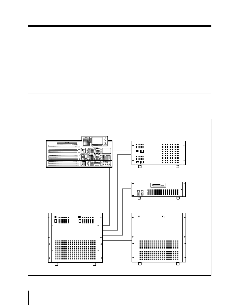
This is the User’s Guide for the BZS-7021A Operation Software for a DVS7300/7350 I/O expansion system. It mainly describes the operation of a DVS7300 I/O expansion system using the BKDS-7011/7012 control panel or a
DVS-7350 I/O expansion system using the BKDS-7021/7022/7023 control
panel.
The “DVS-7300/7350” is a system name. It does not refer to any specific
hardware device.
DVS-7300/7350 I/O Expansion System Configuration
Configuration of a DVS-7300 I/O expansion system (3-M/E)
BKDS-7011/7012 Switcher Control Panel (3-M/E)
DVS-7000A Digital Video Switcher
DMK-7000 Digital Multi Keyer
BKDS-7700 Tally Interface Unit
DVS-V6464M or HDS-X3600
Digital Video Routing Switcher
a)
a)
1-2
a) These units can be included as options in a DVS-7300 I/O expansion system.
Chapter 1 Overview
Page 13
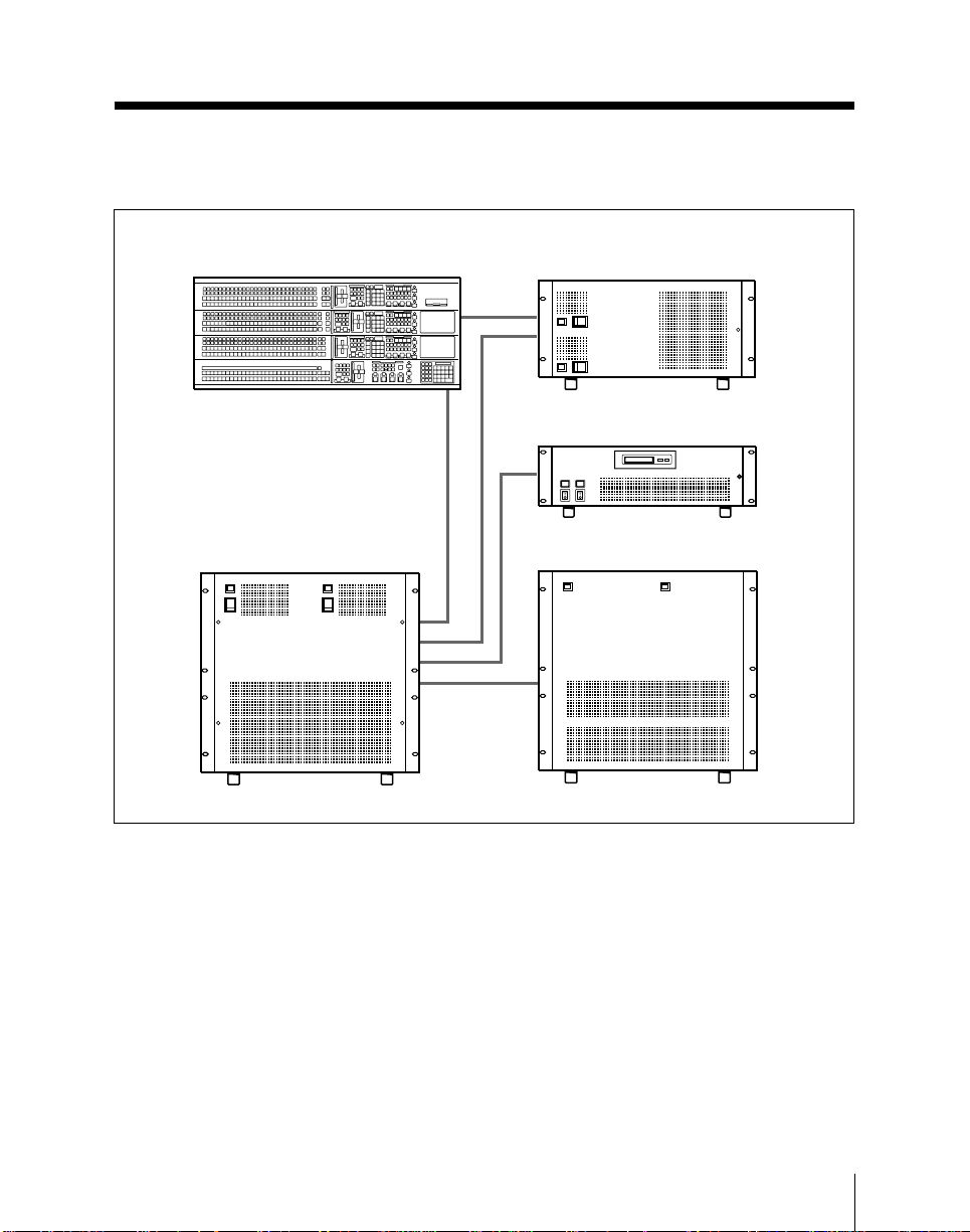
Configuration of a DVS-7350 I/O expansion system (3.5-M/E)
BKDS-7021/7022/7023 Switcher Control
Panel (3.5-M/E)
DMK-7000 Digital Multi Keyer
BKDS-7700 Tally Interface Unit
DVS-V6464M or HDS-X3600
DVS-7000A Digital Video Switcher
a) The BKDS-7700 Tally Interface Unit can be included as an option in a DVS-7350
I/O expansion system.
Digital Video Routing Switcher
a)
Chapter 1 Overview
1-3
Page 14

Introduction
System Configurations and Terminology
This manual refers to the principal components of the DVS-7300/7350 I/O
expansion system by the terms listed below.
Terms for system components
The following table lists the full model names of system components and the
terms used to identify them in this manual.
Full model name
DVS-7000A Digital Video Switcher Switcher
BKDS-7021/7022/7023 TYPE-4D
Switcher Control Panel
BKDS-7011/7012 TYPE-3D Switcher
Control Panel
DVS-V6464M, HDS-X3600
Digital Video Routing Switcher
BZS-7021A Operation Software Software
DMK-7000 Digital Multi Keyer Downstream keyer
BKDS-7032 DSK Control Panel Unit Downstream keyer control section
BKDS-7700 Tally Interface Unit Tally unit
DME-7000 or other Digital Multi Effects
unit
a) Unless it is necessary to distinguish “3.5-M/E panel” and “3-M/E panel” the term “control
panel” is used.
b) In a 3.5-M/E panel, the downstream keyer control section is built-in as standard.
Term used in this manual
3.5-M/E panel
3-M/E panel
Routing switcher or I/O expansion unit
DME unit
a)
a)
b)
Terms for system types
This manual also uses the terms listed below to distinguish different types of
system where necessary.
System characteristics Term used
• Switcher system using a 3.5-M/E panel (BKDS-7021/7022/7023)
as the switcher control panel
• Switcher system with a DMK-7000 Digital Multi Keyer connected
Switcher system using a 3-M/E panel (BKDS-7011/7012) as the
switcher control panel
System equipped with an option board and with system settings to
support composite signal format
System equipped with an option board and with system settings to
support component signal format
a) In the case of a system equipped with a DMK-7000 and BKDS-7032 DSK Control Panel Unit,
where required the term “3-M/E system equipped with a downstream keyer” is also used.
DVS-7350 I/O
expansion system
or 3.5-M/E system
DVS-7300 I/O
expansion system
or 3-M/E system
D2 system
D1 system
a)
1-4
Chapter 1 Overview
Page 15
About the BZS-7021A Operation Software
The BZS-7021A Operation Software is a program for operating the DVS7300/7350 I/O expansion system hardware from the control panel.
For the BKDS-7700 Tally Interface Unit, the special-purpose BZS-7721
Operation Software for incorporation into a DVS-7300/7350 I/O expansion
system is supplied.
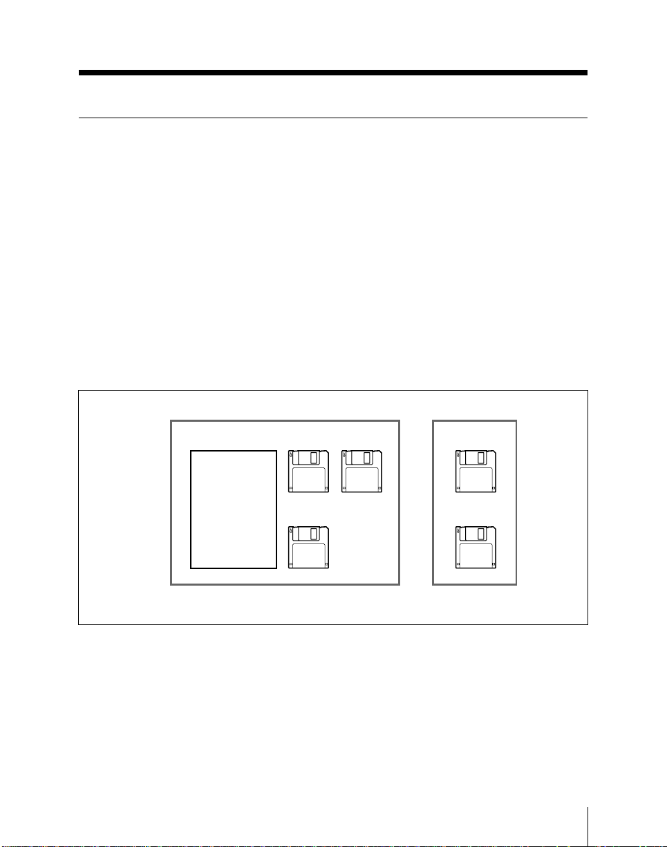
The BZS-7021A comprises the following:
(1) BZS-7021A User’s Guide (this volume)
(2) BZS-7021A SYSTEM DISK 1
(3) BZS-7021A SYSTEM DISK 2
(4) BZS-7021A SYSTEM DISK 3
(5) BZS-7721 SYSTEM DISK 1
(6) BZS-7721 SYSTEM DISK 2
(1) (2)
BZS-7021A
(4)
User’s Guide
BZS-7021A software
a) The BZS-7021A software is supplied on three floppy disks, one for the switcher, one for the
control panel, and one for the DSK.
For details of the method of installing the BZS-7021A software, see page 14-6 or the DVS7000A Installation Manual.
b) The BZS-7721 software is supplied on two floppy disks, one for the tally unit itself, and one
for setup.
For details of the method of installing the BZS-7721 software, see the BKDS-7700 Installation
Manual.
(3)
a)
(5)
(6)
BZS-7721 software
Chapter 1 Overview
b)
1-5
Page 16

Introduction
Related Manuals
Model Name Supplied Manuals
DVS-7000A Digital Video Switcher Operation Manual
DMK-7000 Digital Multi Keyer Operation Manual
DVS-V6464M Digital Video Routing Switcher Operation Manual
HDS-X3600 Digital Video Routing Switcher Operation Manual
BKDS-7700 Tally Interface Unit Operation Manual
Installation Manual
Maintenance Manual Part 1
Installation Manual
Maintenance Manual Part 1
Installation Manual
Maintenance Manual Part 1
Installation Manual
Maintenance Manual Part 1
Installation Manual
Maintenance Manual Part 1
System Setup Manual
1-6
Chapter 1 Overview
Page 17

Features of the DVS-7300/7350
I/O Expansion System
The DVS-7300/7350 I/O expansion system comprises a DVS-7300/7350
system centered on a DVS-7000A, in combination with a DVS-V6464M or
HDS-X3600 Digital Video Routing Switcher. The primary inputs, signal
matrix, and so on of the DVS-7000A are replaced by the DVS-V6464M or
HDS-X3600, thus increasing the number of inputs and outputs.
Features
Support for large-scale live systems
Wide range of inputs and outputs
This system supports a wide range of inputs and outputs, including 60
primary inputs, 28 auxiliary outputs, and five assignable outputs. It is ideal
for use in a large outside broadcast vans and large live productions using
substantial numbers of cameras, VTR materials, and monitor feeds.
Source assignment at the video and key levels
The source assignment to cross-point button selections introduces the concept
of video level and key level; by means of a virtual level of key source
assignment to buttons, more efficient source assignment is possible. The
AUTO SELECT function (linking the video source and key source) also
follows these settings.
Full range of preview functions (AUTO PVW2, SHOW KEY)
When an M/E PVW (mix/effect preview) or PST (preset) is selected on the
EDIT PVW (edit preview) bus, an automatic output switch to the M/E PGM
or M/E PVW signal can be made according to the on-air status of the M/E or
crosspoint selections on the PGM and PST buses (AUTO PVW2). Also, with
a simple button operation the key source selected on an M/E keyer can be
output to EDIT PVW (SHOW KEY function).
Full-featured video effects
M/E banks
There are three M/E banks, each with equivalent functionality. Each bank
includes two keyers which can be operated independently and
simultaneously.
The output from any M/E bank can be input as a background signal to any
other, for further keying and other operations.
Chapter 1 Overview
1-7
Page 18

Features of the DVS-7300/7350 I/O Expansion System
PGM/PST bank (operation coupled to a DMK-7000)
In a DVS-7350 I/O expansion system, the three M/E banks are supplemented
by a PGM/PST bank, for manipulating the final program output from the
switcher. Using the PGM/PST bank, you can insert a total of four
downstream keys into the final background output. These operations are
controlled from the switcher control panel, but the processing is carried out
by a DMK-7000 Digital Multi Keyer connected to the system.
In a DVS-7300 I/O expansion system, by connecting a DMK-7000, and
equipping the control panel with a BKDS-7032 DSK Control Panel Unit, you
can again control the insertion of a maximum of four downstream keys.
In this case, the four downstream keyers are equipped with the same
functions, including key source selection, video and key source linking, key
memory, as the M/E keyers. Even though a separate unit, there is integral
operation with the switcher.
DME wipes (operation coupled to a DME)
By connecting a DME-7000 or other Digital Multi Effects unit, you can use
the control panel to carry out DME wipes, using DME effects (the “DME
LINK™” function).
System configuration flexibility
Wide range of options
In addition to the two basic control panel types, that is, 3.5-M/E and 3-M/E
panels, there is a wide range of options, allowing just the features required to
be installed in a system.
Support for D1 and D2 formats
Except for some options, both D1 (component) and D2 (composite) signal
formats are supported. A simple control panel operation switches between
the D1 and D2 selections, and also in the case of D1 format between 525- and
625-line systems.
Convenient interfaces with external equipment
Using the DVS-7300/7350 I/O expansion system along with the DVSV6464M Routing Switcher via the BKDS-7700 Tally Interface Unit, you can
make up a large-scale switcher system.
Connecting the BVE-9100 Editing Control Unit to your system will allow
you to carry out such advanced editing operations as ISR (Intelligent Status
Reporting) system and EDL (Edit Decision List ) management.
1-8
Chapter 1 Overview
Page 19

The system is provided with VTR control for controlling external devices
such as VTRs, and a PERIPHERAL II timeline.
Powerful remote control functions
You can connect the BKDS-2010 Control Panel to the DVS-7000A and use it
as a separate panel exclusively for the M/E banks.
For key adjustment operations such as chroma key adjustment, the BKDS7060 Keyer Remote Control Panel is available.You can use the dedicated
panel connected to the DVS-7000A to remote-control the auxiliary bus and
Shot Box operations.
Operation adapted to live operation
The DVS-7300/7350 I/O expansion system control panel is designed to
provide the necessary rapid operability for the live broadcast environment.
Combined use of menu settings and button operation
All detailed settings for video processing are carried out in menus, but for
some more frequently used operations you can carry out the selections and
adjustments by direct button operations on the control panel. In particular,
clip, gain, density and other basic parameter settings can be controlled using
the three knobs provided on each M/E bank, quite independently of the
currently accessed menu.
Snapshot function
The DVS-7300/7350 I/O expansion system has a comprehensive snapshot
function, which allows a collection of settings for a particular effect to be
saved in memory, and recalled as required for an instant return to the settings.
Snapshots can be saved from memory to floppy disk, and reloaded into the
system when required.
Snapshots can reflect the overall system settings, or can apply only to key,
wipe, or DME wipe settings for a particular M/E bank. These latter can be
easily saved and recalled using the buttons of the FlexiPad™ provided on the
M/E bank.
Chapter 1 Overview
1-9
Page 20

Features of the DVS-7300/7350 I/O Expansion System
Role of the DVS-V6464M or HDS-X3600 as an I/O
Expansion Unit
In this system, the DVS-V6464M or HDS-X3600 is included as a part of the
switcher system, providing the primary inputs, cross-point switching, source
selecting when the DMK-7000 is connected, and auxiliary bus expansion
functions. Thus the DVS-V6464M or HDS-X3600 serves as a dedicated unit
for expanding the inputs and outputs. It cannot also be used for its standard
function as a routing switcher. In particular, the S-BUS interface is dedicated
as the interface to the DVS-7000A. If you attempt to use an S-BUS interface
to another routing switcher system, this system will no longer operate
correctly.
Input and Output Signals to the DVS-7300/7350 I/O
Expansion System
The principal input/output signal names and the devices and connector names
are shown in the following table.
Signal names Device Connector names
Primary inputs 1 to 60 DVS-V6464M or HDS-X3600 INPUT 1 to 60
Auxiliary outputs 1 to 8 DVS-7000A AUX BUS OUTPUT 1 to 8
Auxiliary outputs 9 to 28 DVS-V6464M or HDS-X3600 OUTPUT 45 to 64
Assignable outputs 1 to 5 DVS-7000A AUX BUS OUTPUT 9 to 13
The signal names and connector names correspond one-to-one. For example, the signal name
“Primary input 1” corresponds to the connector named “INPUT 1.”
For other inputs and outputs, refer to the Operation Manual for the relevant device.
1-10
Chapter 1 Overview
Page 21

Connections Between Devices Within the DVS-7300/
7350 I/O Expansion System
Video signal connections
Video signal connections from DVS-V6464M or HDS-X3600 to
DVS-7000A
DVS-V6464M or HDS-X3600 output DVS-7000A input name
name
OUTPUT 1 to 36 PRIMARY INPUT 1 to 36
The signal names and connector names correspond one-to-one. For example, the signal name
“Primary input 1” corresponds to the connector named “INPUT 1.”
Video signal connections from DVS-V6464M or HDS-X3600 to
DMK-7000
DVS-V6464M or HDS-X3600 output DMK-7000 input name
name
OUTPUT 37 DSK1 VIDEO INPUT
OUTPUT 38 DSK1 KEY INPUT
OUTPUT 39 DSK2 VIDEO INPUT
OUTPUT 40 DSK2 KEY INPUT
OUTPUT 41 DSK3 VIDEO INPUT
OUTPUT 42 DSK3 KEY INPUT
OUTPUT 43 DSK4 VIDEO INPUT
OUTPUT 44 DSK4 KEY INPUT
Video signal connections from DVS-7000A to DVS-V6464M or
HDS-X3600
DVS-7000A output name DVS-V6464M or HDS-X3600 input
name
M/E1 PGM OUTPUT INPUT 61
M/E2 PGM OUTPUT INPUT 62
M/E3 PGM OUTPUT INPUT 63
Chapter 1 Overview
1-11
Page 22
Features of the DVS-7300/7350 I/O Expansion System
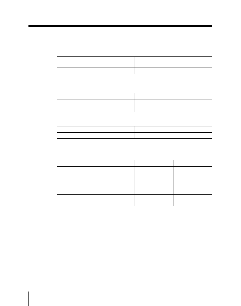
Video signal connections from DMK-7000 to DVS-V6464M or
HDS-X3600
DVS-7000A output name DVS-V6464M or HDS-X3600 input
DSK4 PGM OUTPUT
a) This depends on the system configuration, but connect the final program output.
a)
Video signal connections from DVS-7000A to DMK-7000
DVS-7000A output name DMK-7000 input name
PGM OUTPUT PGM/BKGD1 INPUT
PST OUTPUT PST/BKGD2 INPUT
Video signal connections from DMK-7000 to DVS-7000A
DMK-7000 output name DVS-7000A input name
DSK4 PVW OUTPUT
a) This depends on the system configuration, but connect the final preview output.
a)
Control signal connections
Device Connector Device name Connector name
BKDS-7011/7012/ SWITCHER DVS-7000A PANEL1
7021/7022/7023
BKDS-7011/7012/ DSK DMK-7000 PANELA
7021/7022/7023
DVS-7000A DSK DMK-7000 SWER
DVS-7000A MATRIX
a) The MATRIX connector is a D-sub 9-pin connector. Use the D-sub 9-pin to BNC adapter
provided with the DVS-7000A to make the connection.
On the REMOTE1 connector of the DVS-V6464M/HDS-X3600 use the T-connector and 75ohm terminator provided with the DVS-V6464M/HDS-X3600, and terminate one side of the
T-connector.
name
INPUT 64
DIRECT INPUT
a)
DVS-V6464M REMOTE1
or HDS-X3600 (S-BUS)
1-12
Chapter 1 Overview
Page 23

Settings on the DVS-V6464M/HDS-X3600 Routing
Switcher
The following are the settings on the DVS-V6464M/HDS-X3600 routing
switcher for use in the DVS-7300/7350 I/O expansion system.
DVS-V6464M
CPU board switch settings
Switch S1 (STATION ADDRESS)
Bit No Setting
1 0(OFF)
2 1(OPEN)
3 0(OFF)
4 0(OFF)
5 0(OFF)
6 0(OFF)
7 0(OFF)
8 0(OFF)
The above settings are for the case in which the “Station No.” is 2.
Switch S2
Bit No Setting
1(PRIORITY SELECT) 1(OPEN:S-BUS)
2 0(OFF)
3 1(OPEN)
4 1(OPEN)
5 0(OFF)
6 0(OFF)
7 0(OFF)
8 0(OFF)
Chapter 1 Overview
1-13
Page 24
Features of the DVS-7300/7350 I/O Expansion System
Switch S3 (TEST): 0
Switch S4
Bit No Setting
1(SYNC/ASYNC) OFF(SYNC)
2(M/S) OFF(S)
3(TERMINAL/ISR) OFF(TERMINAL)
4 OFF
Terminal setting initialization
After making the above switch settings, be sure to carry out the following
procedure.
If a backup CPU board is installed, carry this out with one CPU board
removed, and carry out the same procedure for each of the CPU boards.
1 Set the rotary switch S3 (TEST) on the CPU board to the D position.
2 Press the RESET button, to initialize the settings.
3 Return the rotary switch S3 (TEST) on the CPU board to the 0 position.
1-14
Once the procedure has been completed for both boards, reinstall the boards
as originally.
HDS-X3600
CPU board switch settings
Switch S1 (STATION ADDRESS)
Bit No Setting
1 0(CLOSE)
2 1(CLOSE)
3 0(CLOSE)
4 0(CLOSE)
5 0(CLOSE)
6 0(CLOSE)
7 0(CLOSE)
8 0(CLOSE)
The above settings are for the case in which the “Station No.” is 2.
Chapter 1 Overview
Page 25

Switch S2
Bit No Setting
1(REMOTE1 BAUD) 0(CLOSE:312Kbps)
2(P/S) 0(CLOSE:S)
3(SYNC/ASYNC) 0(CLOSE:SYNC)
4(REMOTE3 BAUD) 0(CLOSE:38.4Kbps)
5(TABLE DATA SIZE) 0(CLOSE:128bytes)
6 0(CLOSE)
7 0(CLOSE
8(DEBUG MODE) 0(CLOSE:NORMAL)
Switch S5 (TEST): 0
Terminal setting initialization
After making the above switch settings, be sure to carry out the following
procedure.
If a backup CPU board is installed, carry this out with one CPU board
removed, and carry out the same procedure for each of the CPU boards.
1 Set the rotary switch S5 (TEST) on the CPU board to the D position.
2 Press the RESET button, to initialize the settings.
3 Return the rotary switch S5 (TEST) on the CPU board to the 0 position.
Once the procedure has been completed for both boards, reinstall the boards
as originally.
Chapter 1 Overview
1-15
Page 26

Features of the DVS-7300/7350 I/O Expansion System
Principal Functions
Video level and key level
The DVS-7300/7350 I/O expansion system has 60 primary inputs, and
among these will be paired video (key fill) and key (key source) signals,
including signals from CGs, DMEs, and so on. A key signal is principally
used only for keying, and is not normally selected on a background bus. In
this system, the key signal can be associated with a particular video signal,
and the two can be handled together by a single cross-point button
assignment, thus making button assignments more efficient.
This setting is carried out in the XPT ASSIGN menu, and after assigning a
video and key signal pair to a cross-point button, it is also applied to the
“AUTO SELECT” function.
For details of the video level and key level settings, see the section “Carrying
out setup relating to assigning input signals to the cross-point buttons (XPT
ASSIGN menu)” (page 14-62).
The signal assigned to the “key level” of a particular cross-point button
number can only be selected on certain buses . The following describes the
buses on which key signals can be selected, and how to select a required key
signal on the buses.
1-16
Key source buses
Hold down the SPLIT button in the keyer control section, and select any key
signal on the KEY bus of this keyer.
For a DSK, in the DSK FILL/SOURCE menu hold down the SPLIT button
and select any key signal in the AUX bus control section.
AUX buses 1 to 28, EDIT PVW bus, FM1/FM2 buses, ME UTIL bus
Hold down the V/K button in the AUX bus control section, and select any
key signal. When selecting a key signal with the BKDS-7080/7081 (AUX
BUS REMOTE PANEL), similarly hold down the V/K button and select any
key signal.
Note
On the M/E BKGD-A/B buses and KEY FILL buses, the PGM/PST buses
and the DSK FILL buses, it is not possible to select the signal assigned to the
key level.
Chapter 1 Overview
Page 27

Auxiliary (AUX) buses
There are two sets of auxiliary buses: auxiliary buses 1 to 8 output from the
DVS-7000A, and auxiliary buses 9 to 28 output from the DVS-V6464M or
HDS-X3600. Note the following characteristics of these two sets.
Auxiliary buses 1 to 8
Any signal, including switcher internal signals, can be output.
All signals are output with a 1H delay from the reference signal. (The DVS7000A and DMK-7000 output signals are all at the same timing.)
Auxiliary buses 9 to 28
The program outputs (M/E1 PGM, M/E2 PGM, M/E3 PGM, and FINAL
PGM) and primary inputs 1 to 60 can be output.
All signals are output depending on the input timing, without internal process
delay (1H).
If you select an internal signal on a DVS-7000A assignable output or
auxiliary bus 1 to 8, and return it to a primary input, then an internal signal
can also be selected on auxiliary buses 9 to 28. In this case, however, the
output is delayed by 1H with respect to other primary inputs.
(Since the program output from the DVS-7000A or DMK-7000 is rerouted
through the routing switcher, there is a 1H delay in the output timing.)
Switch preview and AUTO PVW2 (auto preview 2) functions
This system provides a switchable preview on the EDIT PVW bus. By setting
the programmable buttons in the DSK control section to PVW SELECT, you
can easily switch the EDIT PVW output from among the M/E1 PVW, M/E2
PVW, M/E3 PVW, EXT(DIRECT IN:FINAL PVW), and PST (AUTO
PVW2).
With the auto preview 2 function, preview outputs are automatically switched
between the PGM and PVW buses to give an appropriate monitor signal
according to whether the M/E is on air or not. When AUTO PVW2 in the
OUTPUT ASSIGN setup menu is set to EDPV, this applies to the EDIT
PVW bus only; if it is set to ALL, this applies to the EDIT PVW, AUX 1 to
8, and ASSIGN OUT1 to 5 buses.
For details, see page 14-33.
Chapter 1 Overview
1-17
Page 28

Features of the DVS-7300/7350 I/O Expansion System
Show key function
By means of the show key function you can preview the key source signal to
an M/E keyer with a simple button operation. Holding down the keyer
selection button in the M/E keyer control section for at least one second
outputs the key source signal from the keyer to EDIT PVW for a
predetermined period.
There are two settings of the function, so that the show key output appears on
the EDIT PVW only, or also on auxiliary buses 1 to 8 and ASSIGN OUT1 to
5.
Peripheral 2 timeline
For all of the devices, with a device ID of 0 to 23, valid in the PERIPHERAL
II protocol, LEARN, RECALL, and TRIGGER commands can be
individually assigned on the timeline, and executed as effects. By using a
device controller such as DNF CONTROLS equipped with a PERIPHERAL
II interface, you can carry out timeline control on a VTR, disk recorder, MD
player, or other device. At the same time it is possible to assign PANEL GPI
OUT to the timeline.
For details, see page 8-35.
1-18
Chapter 1 Overview
Page 29

BKDS-7700 Tally Interface Unit
The BZS-7721 software supplied with the BZS-7021A is required when a
BKDS-7700 is connected to this system. It provides equivalent functions to
BZS-7720 V1.21.
Changes in the BKDS-7700 System Setup Manual
When using a BKDS-7700 in this system, there are changes in the source and
destination assignments. Please replace the following pages in the supplied
System Setup Manual.
8-1-4 Switcher Matrix
Replace with page 1-20 of this manual.
8-1-7 Switcher Source Name Setting
Replace with page 1-21 of this manual.
8-1-8 Switcher Crosspoint Assignment
In this system, no particular setting is required for the SERIAL
TALLY connector on the DVS-7000A unit.
8-1-9 Switcher Crosspoint Control
Replace with page 1-22 of this manual.
Chapter 1 Overview
1-19
Page 30

BKDS-7700 Tally Interface Unit
8-1-4 Switcher Matrix
(BKDS-7700 System Setup Manual replacement page)
The switcher matrix is assigned as shown below.
Source
No. Function
1 PRIMARY1
2 PRIMARY2
3 PRIMARY3
::
::
60 PRIMARY60
61~64 (Reserved)
65 BLACK
66 BKGD COLOR1
67 BKGD COLOR2
68 BKGD COLOR3
69 BKGD COLOR4
70 (Reserved)
71 PROGRAM
72 CLEAN
73 M/E-1 PGM
74 M/E-2 PGM
75 M/E-3 PGM
76 to 101 (Reserved)
102 CHROMAKEY1
103 CHROMAKEY2
104 CHROMAKEY3
105 CHROMAKEY4
106 to 128 (Reserved)
Destination
No. Function
1 M/E-1 PGM
2 (Reserved)
3 M/E-2 PGM
4 (Reserved)
5 M/E-3 PGM
6 (Reserved)
7 PROGRAM
8 to 16 (Reserved)
17 AUX BUS1
18 AUX BUS2
19 AUX BUS3
20 AUX BUS4
21 AUX BUS5
22 AUX BUS6
23 AUX BUS7
24 AUX BUS8
25 to 31 (Reserved)
32 EDIT PVW
33 AUX BUS9
34 AUX BUS10
::
::
60 AUX BUS28
61 to 64 (Reserved)
1-20
Chapter 1 Overview
Page 31

8-1-7 Switcher Source Name Setting
(BKDS-7700 System Setup Manual replacement page)
To perfrom the source name interface operation using an S-bus connection,
set the switcher source name in the S-bus according to the list shown below.
No. Function
1 PRIMARY1
2 PRIMARY2
3 PRIMARY3
::
::
60 PRIMARY60
61 to 64 (Reserved)
65 BLACK
66 M/E-1 COLOR BKGD
67 M/E-2 COLOR BKGD
68 M/E-3 COLOR BKGD
69 (Reserved)
70 SELF COLOR BKGD
71 PROGRAM
72 CLEAN
73 M/E-1 PGM
74 M/E-2 PGM
75 M/E-3 PGM
76 M/E-2 CHR KEY KEY
77 M/E-3 CHR KEY KEY
78 M/E-2 KEY1 PROC VIDEO
79 M/E-2 KEY1 PROC KEY
80 M/E-2 KEY2 PROC VIDEO
81 M/E-2 KEY2 PROC KEY
82 PRESET
83 M/E-1 PVW
84 M/E-2 PVW
85 M/E-3 PVW
86 M/E-3 KEY1 PROC VIDEO
87 M/E-3 KEY1 PROC KEY
88 M/E-3 KEY2 PROC VIDEO
89 M/E-3 KEY2 PROC KEY
90 FRAME MEMORY1
91 FRAME MEMORY2
92, 93 (Reserved)
94 M/E-1 CHR KEY KEY
95 (Reserved)
96 M/E-1 CHR KEY FRGD
97 M/E-2 CHR KEY FRGD
98 M/E-3 CHR KEY FRGD
99 (Reserved)
100 CCR OUT1
101 CCR OUT2
102 to 105 (Reserved)
106 FINAL PROGRAM
107 INTERNAL DME1 VIDEO
108 INTERNAL DME1 KEY
109 INTERNAL DME2 VIDEO
110 INTERNAL DME2 KEY
111 (Reserved)
112 M/E-1 CLEAN
113 M/E-2 CLEAN
114 M/E-3 CLEAN
115 to 119 (Reserved)
120 M/E-1 KEY1 PROC VIDEO
121 M/E-1 KEY1 PROC KEY
122 M/E-1 KEY2 PROC VIDEO
123 M/E-1 KEY2 PROC KEY
124 DSK OUT RETURN
125 DIRECT IN
126, 127 (Reserved)
Chapter 1 Overview
1-21
Page 32

BKDS-7700 Tally Interface Unit
8-1-9 Switcher Crosspoint Control
(BKDS-7700 System Setup Manual replacement page)
To control the switcher crosspoint using an S-bus connection, specify the
destination according to the list shown below.
Note
In the following table, the auxiliary buses are not assigned. When controlling
the auxiliary buses from S-BUS, specify the destination within the switcher
matrix.
No. Function
1 M/E-1 KEY1 FILL
2 (Reserved)
3 M/E-1 KEY2 FILL
4 (Reserved)
5 M/E-1 BKGD A
6 M/E-1 BKGD B
7 (Reserved)
8 (Reserved)
9 M/E-2 KEY1 FILL
10 (Reserved)
11 M/E-2 KEY2 FILL
12 (Reserved)
13 M/E-2 BKGD A
14 M/E-2 BKGD B
15 (Reserved)
16 (Reserved)
17 M/E-3KEY1 FILL
18 (Reserved)
19 M/E-3KEY2 FILL
20 (Reserved)
21 M/E-3 BKGD A
22 M/E-3 BKGD B
23 (Reserved)
24 (Reserved)
25 P/P KEY1 FILL
26 (Reserved)
27 P/P KEY2 FILL
28 (Reserved)
29 P/P BKGD A
30 P/P BKGD B
31 to 64 (Reserved)
1-22
Chapter 1 Overview
Page 33

Chapter 2
Location and Function of Parts
Overall Organization.................................................................................2-2
Mix/Effects Banks...................................................................................... 2-7
Signal Selection Section ...................................................................... 2-8
Transition Control Section.................................................................2-11
FlexiPad™ ......................................................................................... 2-14
Key Control Section .......................................................................... 2-16
Program/Preset Bank .............................................................................. 2-20
Signal Selection Section .................................................................... 2-21
Transition Control Section.................................................................2-22
Downstream Keyer Control Section.................................................. 2-24
Auxiliary Bus Bank ................................................................................. 2-27
Numeric Keypad Section ........................................................................ 2-29
Menu Control Section and Floppy Disk Drive......................................2-31
Key Frame Control Section
(BKDS-7030 Key Frame Control Panel Unit – Option)............... 2-33
DME Control Section
(BKDS-7031 DME Control Panel Unit – Option) ........................ 2-36
SHOT BOX Control Section
(BKDS-7033 Memory Recall Control Panel Unit – Option)........2-39
Page 34
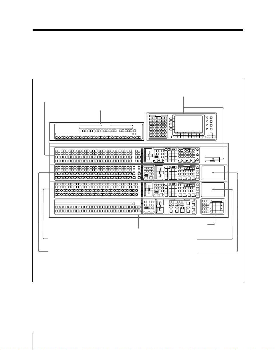
Overall Organization
Overall Organization
The control panel is divided into several
blocks of buttons and other controls, as
shown in the illustrations on this and the
following pages.
M/E-1 bank (page 2-7)
Auxiliary bus bank (page 2-27)
AUX
M/E-1
K1
K2
A
B
M/E-2
K1
K2
A
B
M/E-3
K1
K2
A
B
BLACK
PGM
BLACK
PST
See the page numbers indicated in
parenthesis for more details.
Menu control section and
floppy disk drive (page 2-31)
2-2
Numeric keypad sectiona) /
option fitting panel 3 (page 2-29)
Option fitting panel 2
Option fitting panel 1
M/E-3 bank (page 2-7)
M/E-2 bank (page 2-7)
PGM/PST bank
(page 2-20)
a)It is possible to fit the numeric keypad section in any of the three option fitting panels.
BKDS-7021 Type 4D control panel (3.5-M/E panel)
Chapter 2 Location and Function of Parts
Page 35
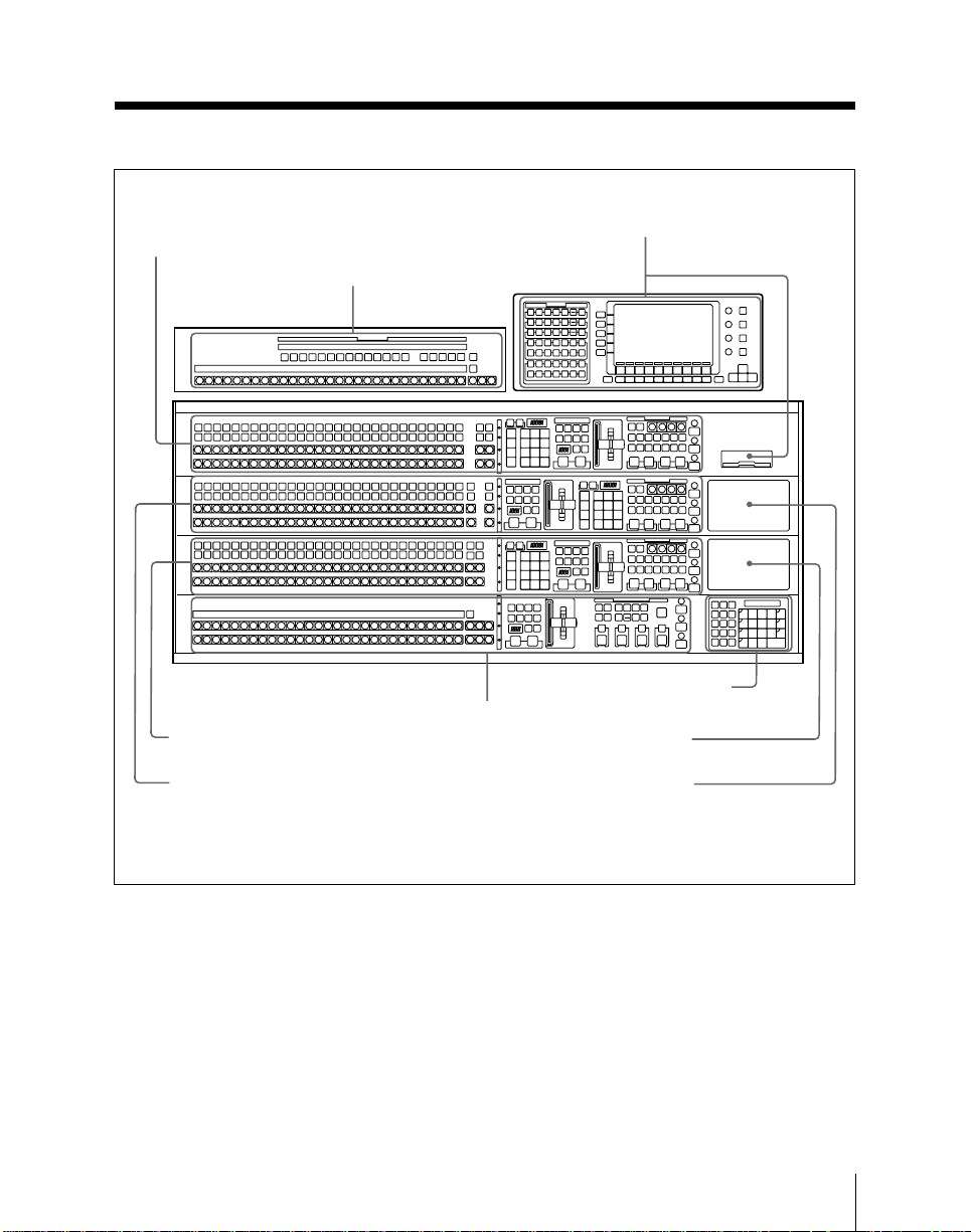
M/E-1 bank (page 2-7)
Auxiliary bus bank (page 2-27)
AUX
M/E-1
K1
K2
A
B
M/E-2
K1
K2
A
B
M/E-3
K1
K2
A
B
PGM
PST
M/E-3 bank (page 2-7)
PGM/PST bank
(page 2-20)
Menu control section and
floppy disk drive (page 2-31)
Numeric keypad sectiona) /
option fitting panel 3 (page 2-29)
Option fitting panel 2
M/E-2 bank (page 2-7)
Option fitting panel 1
a)It is possible to fit the numeric keypad section in any of the three option fitting panels.
BKDS-7022 Type 4D control panel (3.5-M/E panel)
Chapter 2 Location and Function of Parts
2-3
Page 36
Overall Organization
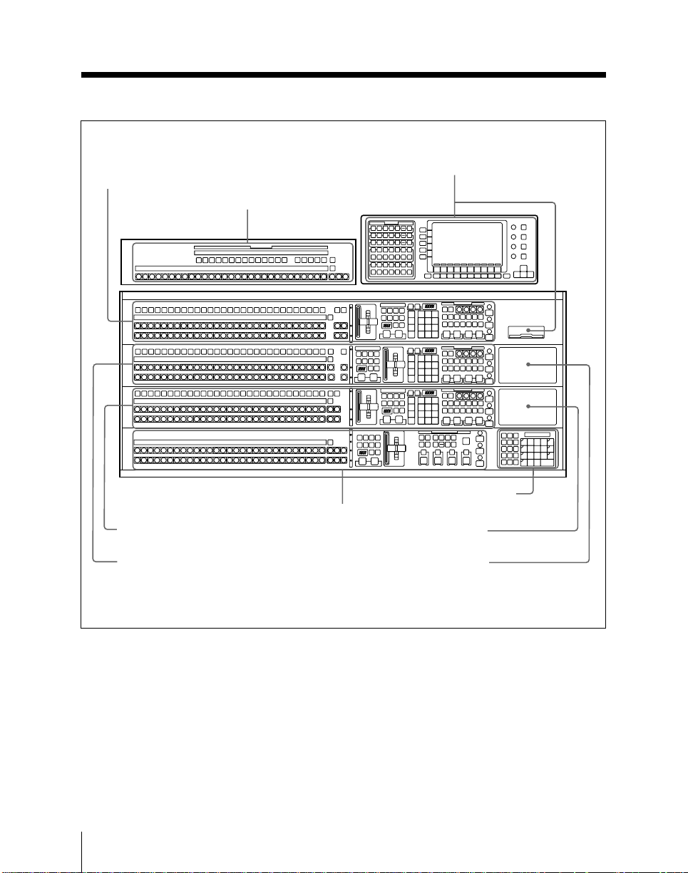
M/E-1 bank (page 2-7)
Auxiliary bus bank (page 2-27)
AUX
M/E-1
K1
K2
A
B
M/E-2
K1
K2
A
B
M/E-3
K1
K2
A
B
PGM
PST
Menu control section and
floppy disk drive (page 2-31)
2-4
Numeric keypad sectiona) /
option fitting panel 3 (page 2-29)
Option fitting panel 2
Option fitting panel 1
M/E-3 bank (page 2-7)
M/E-2 bank (page 2-7)
PGM/PST bank
(page 2-20)
a)It is possible to fit the numeric keypad section in any of the three option fitting panels.
BKDS-7023 Type 4D control panel (3.5-M/E panel)
Chapter 2 Location and Function of Parts
Page 37
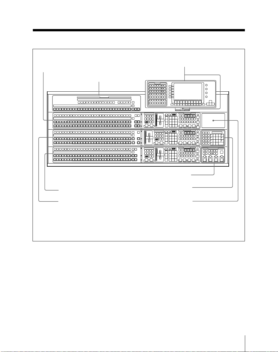
Menu control section and
floppy disk drive (page 2-31)
M/E-1 bank (page 2-7)
Auxiliary bus bank (page 2-27)
AUX
M/E-1
K
A
B
M/E-2
K
A
B
M/E-3
K
A
B
Downstream keyer control section /
option fitting panel 3a) (page 2-24)
M/E-3 bank (page 2-7)
M/E-2 bank (page 2-7)
Numeric keypad section / option
fitting panel 2b) (page 2-29)
Option fitting panel 1
a)It is possible to fit the optional downstream keyer control section in any of the three option
fitting panels.
b)It is possible to fit the numeric keypad section in any of the three option fitting panels.
BKDS-7011 Type 3D control panel (3-M/E panel)
Chapter 2 Location and Function of Parts
2-5
Page 38
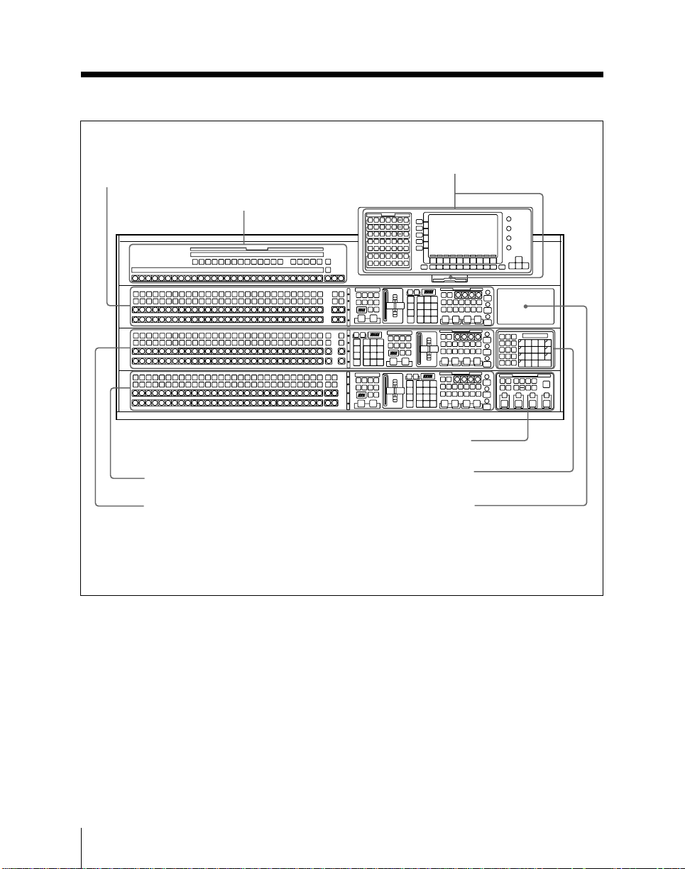
Overall Organization
M/E-1 bank (page 2-7)
Auxiliary bus bank (page 2-27)
AUX
M/E-1
K
A
B
M/E-2
K
A
B
M/E-3
K
A
B
M/E-3 bank (page 2-7)
M/E-2 bank (page 2-7)
Menu control section and
floppy disk drive (page 2-31)
Downstream keyer control section /
option fitting panel 3a) (page 2-24)
Numeric keypad section / option
fitting panel 2b) (page 2-29)
Option fitting panel 1
2-6
a)It is possible to fit the optional downstream keyer control section in any of the three option
fitting panels.
b)It is possible to fit the numeric keypad section in any of the three option fitting panels.
BKDS-7012 Type 3D control panel (3-M/E panel)
Chapter 2 Location and Function of Parts
Page 39
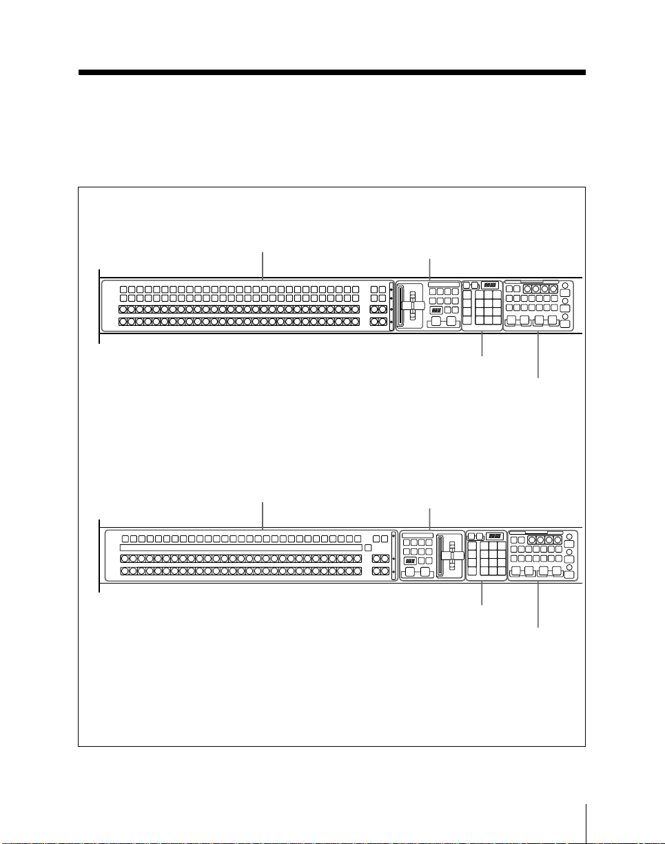
Mix/Effects Banks
The three mix/effects banks (M/E-1, M/E2, and M/E-3) provide separate mix/effects
functionality.
BKDS-7012/7021/7022
M/E-1
K1
K2
A
BLACK
BLACK
B
BKDS-7011/7023
a)
Signal selection section
(page 2-8)
a)
Signal selection section
(page 2-8)
These three banks are functionally and
structurally similar; the following
illustration shows the M/E-1 bank by way
of example.
Transition control section
(page 2-11)
FlexiPad™ (page 2-14)
Key control section
(page 2-16)
Transition control section
(page 2-11)
M/E-1
K
A
B
a)Depending on the control panel model and the
M/E bank, the positions of the transition control
section and the FlexiPad may be reversed.
M/E bank
FlexiPad™ (page 2-14)
Key control section
(page 2-16)
Chapter 2 Location and Function of Parts
2-7
Page 40
Mix/Effects Banks
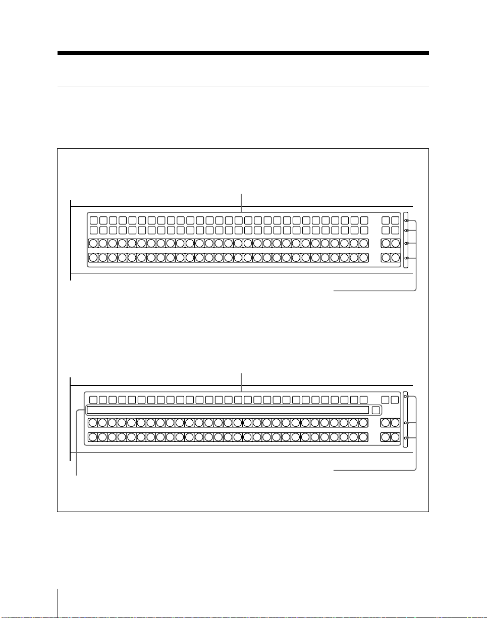
Signal Selection Section
This is used for selecting signals on this
M/E bank.
BKDS-7012/7021/7022
1 Cross-point buttons
M/E-1
K1
K2
A
BLACK
BLACK
B
BKDS-7011/7023
M/E-1
K
A
BLACK
BLACK
B
3 Source name display
2 Bus tally indicators
1 Cross-point buttons
2 Bus tally indicators
M/E2M/E
3
M/E2M/E
3
COLOR
BKGD
COLOR
BKGD
COLOR
BKGD
COLOR
BKGD
M/E2M/E
SHIFT
SHIFT
SHIFT
SHIFT
3
M/E2M/E
3
M/E2M/E
1
3
M/E2M/E
M/E2M/E
2
3
3
SHIFT
2-8
Signal selection section
Chapter 2 Location and Function of Parts
Page 41

1 Cross-point buttons
These buttons select the signals used for
video making on this M/E bank.
Each row of buttons corresponds to one or
more signal buses within the switcher.
Using a setup menu, you can assign any
signals to the first 29 cross-point buttons
in each row. The two buttons at the right
of each row are reentry buttons for
selecting the output signals from the other
mix/effects banks.
The buttons to which you can assign
signals are numbered 0 to 28 from left to
right. By means of a setup operation, you
can assign the rightmost button (number
28) as a shift button. In this case buttons 0
to 27 can be used to select a second set of
signals, numbered 30 to 57, in the shifted
state. To select these shifted signals, hold
down the SHIFT button then press the
required cross-point button.
It is also possible, using a setup menu
operation, to switch the shift button to be
the leftmost button instead of the
rightmost. In this case the assignable
signals are numbered 1 to 28 and 31 to 58.
The setup menu operation assigns signals
to cross-point button columns, so that
naturally buttons select the same signals
regardless of which bank or row they are
in.
K1 (key 1) and K2 (key 2) rows (BKDS7012/7021/7022), K (key) row (BKDS7011/7023):
These buttons select the key signals to
be inserted into the video on this bank.
• On the BKDS-7012/7021/7022, the
K1 row controls the key 1 fill bus,
and the K2 row the key 2 fill bus.
• On the BKDS-7011/7023, the K row
controls both the key 1 and key 2 fill
buses. To delegate these buttons to
the key 1 fill bus press the KEY 1
button in the key control section,
turning it on, and to delegate these
buttons to the key 2 fill bus press the
KEY 2 button in the key control
section, turning it on.
When the K row is delegated to the
key 1 fill bus, a “1” appears below
the key bus tally indicator, and
similarly a “2” when it is delegated
to the key 2 fill bus.
A row (background bus A): These
buttons select the signal for
background A. Except while
executing a background transition, this
bus provides the output of the mix/
effects block.
B row (background bus B): This bus
provides the second background for a
transition, which replaces the
background currently on bus A.
Chapter 2 Location and Function of Parts
2-9
Page 42

Mix/Effects Banks
Visual indications on cross-point
buttons
The currently selected button in a row (i.e.
the last button pressed) lights amber or
red.
Amber (“low tally”): the signal selected
on the bus does not form part of the
program output from the switcher.
Red (“high tally”): the signal selected on
the bus forms part of the program
output from the switcher.
2 Bus tally indicators
These light when the signal from the
corresponding bus (row of cross-point
buttons) forms part of the output from this
M/E bank.
You can also use these indicators as the
indicators for the video process function.
For more details, see “Changing switcher
functions (OPERATION MODE menu)”
(page 14-66).
3 Source name display (BKDS-7011/
7023 only)
This shows the identifiers of source
signals. When there are two signals
assigned to a cross-point button column,
hold down the SHIFT button at the right
end to show the identifiers assigned to the
shifted buttons.
Again, if the shift button in the cross-point
button row is held down, the second set of
signal names is displayed.
If you are using the switcher and a DVS-B
series routing switcher connected by a
BKDS-7700, the signal names selected on
the routing switcher can be displayed.
2-10
Chapter 2 Location and Function of Parts
Page 43
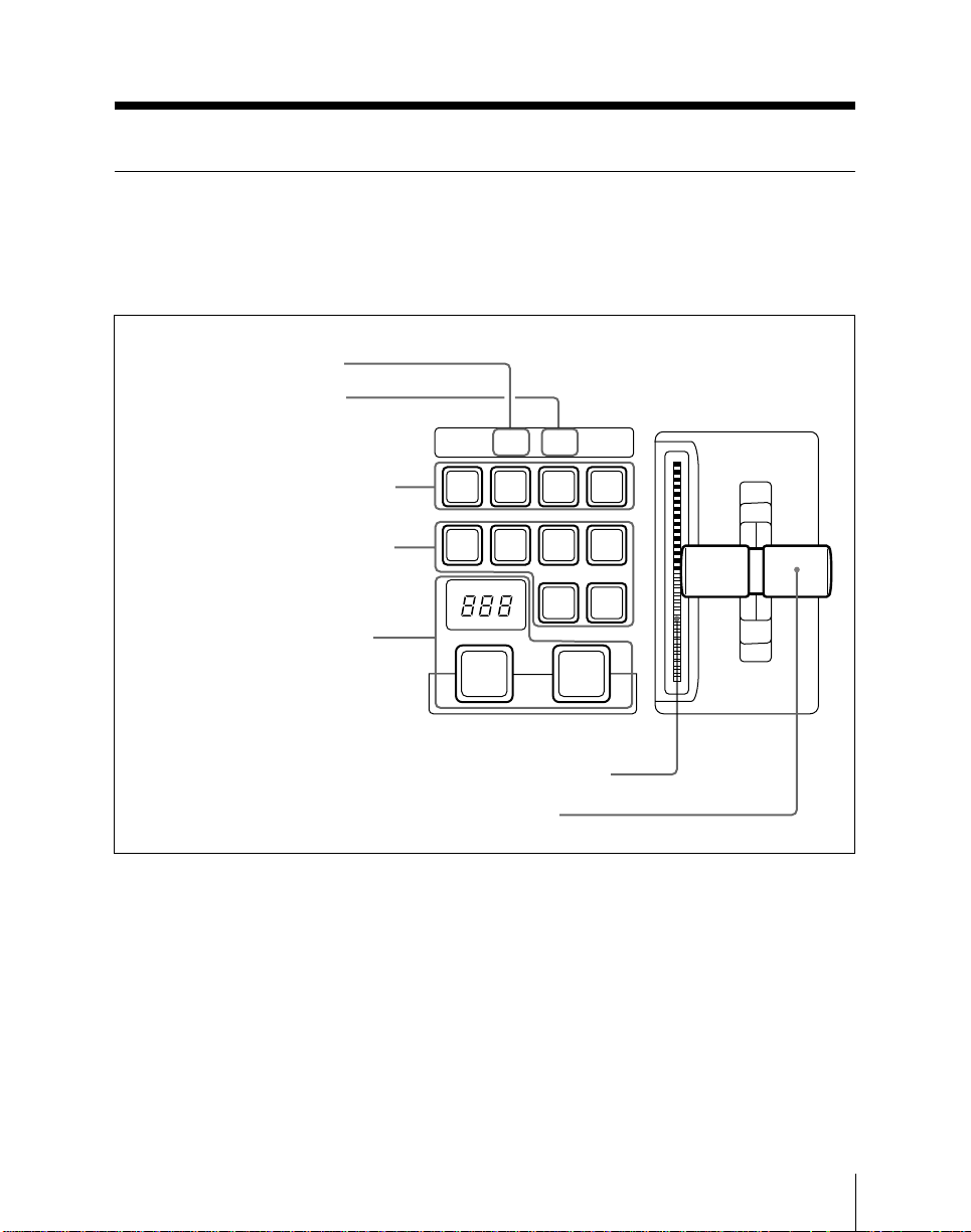
Transition Control Section
The buttons in this section control
transitions on the output from this M/E
bank.
1 Key 1 ON/OVER indicator
2 Key 2 ON/OVER indicator
3 Next transition selection buttons
4 Transition type selection buttons
5 Auto transition control section
BKGD
MIX
FRAMES
AUTO
TRANS
NEXT TRANSITION
ON
OVERONOVER
KEY1KEY KEY
2
SUPER
NAM
MIX
DME
1
TRANSITION TYPE
CUT
PRIOR
WIPE
DME
2
a) Sections A and B are
interchanged on alternate M/E
banks.
Transition control section
1 Key 1 ON/OVER indicator
ON: Lights when key 1 is inserted in the
output from this mix/effects bank.
OVER: Lights when key 1 is over key 2.
Section A
a)
Section B
6 Transition indicator
7 Fader lever
2 Key 2 ON/OVER indicator
ON: Lights when key 2 is inserted in the
output from this mix/effects bank.
OVER: Lights when key 2 is over key 1.
Chapter 2 Location and Function of Parts
a)
2-11
Page 44

Mix/Effects Banks
3 Next transition selection buttons
These buttons determine what the next
transition will apply to.
BKGD: Next transition is a background
transition.
KEY 1: Next transition will insert or
remove key 1. If key 1 is currently
inserted it will be removed, and vice
versa.
KEY 2: Next transition will insert or
remove key 2. If key 2 is currently
inserted it will be removed, and vice
versa.
KEY PRIOR (priority): Next transition
will interchange the priority
relationship between key 1 and key 2.
More than one of these four buttons can be
lit simultaneously.
4 Transition type selection buttons
Press one of these buttons, turning it on, to
determine the type of the next transition.
MIX: In a background transition, the new
video (bus B) fades in as the old video
(bus A) fades out. The new video
level is increased from 0% to 100% as
the old video is reduced from 100% to
0%, in such a way that the overall
signal level is always 100%.
In a key transition, the key fades in
(for insertion) or out (for removal).
NAM (non-additive mix): The old
background and new background
video signals are compared, and the
higher one is used as the output.
The old video is reduced from 100%
to 0% over the second half of the
transition, and the new video level is
increased from 0% to 100% over the
first half, all the while combining the
two signals by non-additive mixing.
You can also use this button as a
programmable button.
For details, see “Changing switcher
functions (OPERATION MODE
menu)” (page 14-66).
SUPER MIX: The old video is reduced
from 100% to 0% over the second half
of the transition, and the new video
level is increased from 0% to 100%
over the first half, all the while
combining the two signals by
(ordinary) mixing.
It is also possible to set the video
levels at the mid-point of the transition
to any value between 0 and 100%, by
using the BKGD/TRANS menu for
the M/E bank.
You can also use this button as a
programmable button.
For details, see “Changing switcher
functions (OPERATION MODE
menu)” (page 14-66).
WIPE: The transition executed will be a
wipe, using the settings in the wipe
setting menu for the M/E bank.
DME 1: The transition will be a wipe-like
effect, using the effects provided by
DME channel 1. This requires at least
one DME-7000 or other Digital Multi
Effects unit to be connected to the
switcher system.
To carry out a dual DME wipe using
the effects provided by two DME
channels, press this button and the
DME 2 button simultaneously, turning
them on.
2-12
Chapter 2 Location and Function of Parts
Page 45

DME 2: The transition will be a wipe-like
effect, using the effects provided by
DME channel 2. This requires at least
two DME-7000 or other DME units to
be connected to the switcher system.
To carry out a dual DME wipe using
the effects provided by two DME
channels, press this button and the
DME 1 button simultaneously, turning
them on.
5 Auto transition control section
Duration display: This shows the
number of frames in the transition
duration. You can set the duration
using the numeric keypad.
AUTO TRANS button: Pressing this
button carries out an auto transition of
the set duration. The transition starts
immediately, and the button lights
amber. When the transition
completes, the button goes off.
While a transition is in progress (i.e.
while the button is lit amber), pressing
the AUTO TRANS button again
pauses the transition, and the AUTO
TRANS button then lights green.
Pressing the button again in this state
resumes the transition, and the AUTO
TRANS button reverts to amber.
CUT button: Pressing this button carries
out the transition as a cut (i.e.
instantaneously).
6 Transition indicator
This comprises 30 LEDs which show the
current status of the transition.
7 Fader lever
This is used to carry out a manual
transition.
Chapter 2 Location and Function of Parts
2-13
Page 46
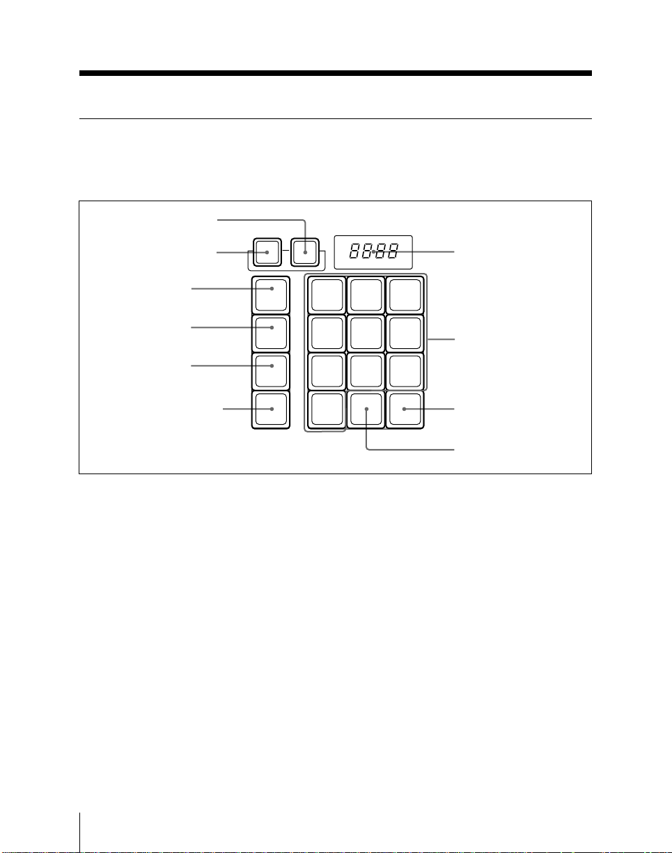
Mix/Effects Banks
FlexiPad™
The FlexiPad™ is used for saving and
recalling snapshots1) of this M/E bank.
1 KEY DSBL button
2 XPT DSBL button
XPT
DSBL
KEY
DSBL
7 Numeric display
3 SHIFT button
4 DME button
5 WIPE button
6 SNAPSHOT button
SHIFT
DME
WIPE
SNAP
SHOT
FlexiPad™
1 KEY DSBL (disable) button
Press this button, turning it on, to apply the
“KEY DISABLE” attribute to the M/E
snapshot next to be recalled. This means
that recalling the snapshot will not change
the current key settings on this M/E bank.
78
4
12
0
DISS
9
56
3
EFF
AUTO
TRANS
8 Numeric keys
9 AUTO TRANS button
q; EFF DISS button
2 XPT DSBL (cross-point disable)
button
Press this button, turning it on, to apply the
“XPT DISABLE” attribute to the M/E
snapshot next to be recalled. This means
that recalling the snapshot will not change
the current signal selections on
background buses A and B on this M/E
bank.
..............................................................................................................................................................................
1) The snapshot function allows you to save a
collection of switcher settings in memory, and
recall them as necessary to use the same settings
2-14
Chapter 2 Location and Function of Parts
again. The collection of settings saved in memory
is itself referred to as a snapshot.
For more details of snapshot operations, see
Chapter 7.
Page 47

3 SHIFT button
Use this button in combination with the
numeric keypad in the FlexiPad when
saving and recalling snapshots.
4 DME button
Use this button when saving or recalling a
DME wipe snapshot.
5 WIPE button
Use this button when saving or recalling a
wipe snapshot.
6 SNAPSHOT button
Use this button when saving or recalling
an M/E snapshot, and also in combination
with the key snapshot buttons in the key
control section when saving or recalling a
key snapshot.
7 Numeric display
• While you are saving or recalling an M/E
snapshot, this shows the snapshot register
number.
• While you are saving or recalling a wipe
or DME wipe snapshot, this shows the
pattern number.
9 AUTO TRANS (transition) button
Press this button, turning it on, to save an
M/E snapshot with the “AUTO
TRANSITION” attribute. Recalling a
snapshot saved with this attribute will
immediately start an auto transition on this
M/E bank.
q; EFF DISS (effect dissolve) button
Press this button, turning it on, to save an
M/E snapshot with the “EFFECT
DISSOLVE” attribute. Recalling a
snapshot saved with this attribute will
cause a smooth change from the current
M/E bank settings to the settings in the
snapshot.
8 Numeric keys
• When saving or recalling an M/E
snapshot, use these keys to specify the
snapshot register number.
• Also when saving or recalling a wipe or
DME wipe snapshot, use this to specify
the register number.
To return to the state before recalling a
wipe or DME wipe snapshot, press the 0
key.
Chapter 2 Location and Function of Parts
2-15
Page 48
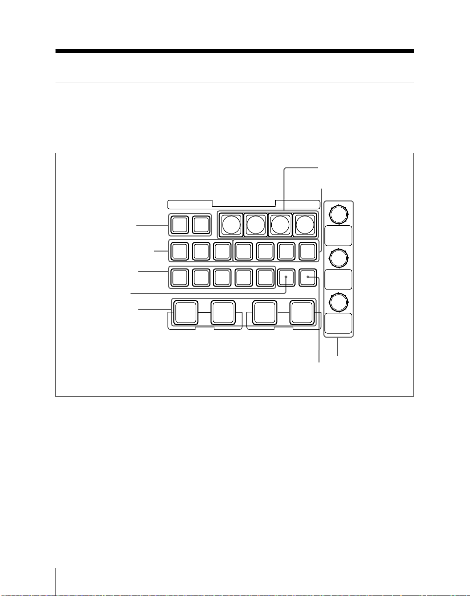
Mix/Effects Banks
Key Control Section
Each M/E bank has two keyers (1 and 2);
the buttons in this section select the keyer
and then control the key operations.
KEY
1 Keyer delegation
buttons
2 Key fill and key source
selection buttons
3 Key type selection
buttons
4 KEY INV button
5 Key insert/remove
buttons
KEY
2
1
MATTE AUTO
SEL
FILL
LUM
LIN
KEY KEY
MIX ON
KEY1 KEY2
1)
KEY CONTROL
23
1
BORD
DROP
BORD
PTM
KEY KEY
MIX ON
SPLIT
CLEAN CHR
9 PROC KEY button
SHDW
KEY
IMV
6 Key snapshot buttons
7 Edge type selection
buttons
4
OUT
LINE
PROC
KEY
8 Key parameter
setting knobs and
displays
1 Keyer delegation buttons
Press the KEY 1 button, turning it on, to
delegate the buttons in the key control
section to keyer 1, and the KEY 2 button
similarly for keyer 2.
On a BKDS-7011/7023, pressing one of
the keyer delegation buttons, turning it on,
not only delegates the buttons in the key
control section, but also delegates the
..............................................................................................................................................................................
1) In this manual, this is referred to as delegating the
buttons in the key control section to keyer 1 or
keyer 2.
2-16
Chapter 2 Location and Function of Parts
Key control section
cross-point buttons in the K row to the key
1 bus or key 2 bus as the case may be.
Holding down any one of these buttons for
at least one second outputs the key source
signal from the corresponding keyer to the
EDIT PVW bus. (“Show key” function)
For details, see page 14-38.
Page 49

2 Key fill and key source selection
buttons
MATTE FILL: Pressing this button,
turning it on, selects a color matte
produced by the switcher as the key
fill signal.
When this button is off, the signal
selected on the key fill bus is used as
the key fill. When all three of this
button, the AUTO SEL button and the
SPLIT button are off, the signal
selected on the key fill bus is also used
as the key source (self-keying).
AUTO SEL (auto selection): Press this
button, turning it on, to use the signal
assigned in a setup menu to the current
key fill as the key source.
SPLIT: Press this button, turning it on, to
use the signal on the key source bus as
the key source. To select the signal on
the key source bus, hold down this
button, and press a cross-point button
in the auxiliary bus bank or in the M/E
bank a cross-point button in the K row
(BKDS-7011/7023) or K1 or K2 row
(BKDS-7012/7021/7022).
To use the signal selected on the key
fill bus as the key source, press both
the SPLIT button and the AUTO SEL
button simultaneously, so that both are
off.
3 Key type selection buttons
LUM (luminance): A hole is cut at a
certain level of the Y (luminance)
signal of the key source, and the key
fill signal inserted.
• In a D2 system, the key source is
passed through a filter, and the
resulting Y signal is used to
determine the key.
• In a D1 system, the key source Y
signal is passed through a filter to
apply S-curve compensation, and the
resulting signal is used to determine
the key.
LIN (linear): A hole is cut in the
background and the key fill signal
inserted. Compared with a luminance
key, there is a reduced variability in
gain.
• In a D2 system, the key source signal
including the chrominance
component is used to determine the
key.
• In a D1 system, the key source Y
signal is used to determine the key.
CLEAN: In a luminance or linear key the
key source is used as a mask on both
the background (i.e. to cut the hole)
and on the key fill (i.e. trimming it to
fill the hole). The clean key
technique, on the other hand, does not
mask the key fill, but simply mixes it
with the background from which the
hole has been cut. This means that the
key fill signal must already be
trimmed to fit the hole (i.e. black
everywhere else).
Chapter 2 Location and Function of Parts
2-17
Page 50

Mix/Effects Banks
CHR (chroma key): A particular hue
(usually blue) in the key source signal
is used to determine the hole to be cut
in the background.
You can use the following signals as
chroma key signals (foreground).
• In a D2 system: an analog
component signal.
• In a D1 system: an analog
component signal, or a primary
input.
PTN (pattern): This uses a wipe pattern
(generated by the dedicated wipe
generators on each M/E bank) to cut
the hole in the background and insert
the key fill. As for a wipe, you can
also apply a variety of modifications
depending on the pattern, but the wipe
direction and edge modifiers are not
available.
4 KEY INV (invert) button
To invert the sense of the key source
signal. Instead of the normal black titling
on a white background, you can use this
function to provide a key source with
white titling on a black background.
You can also use this button as the
programmable button by assigning other
functions.
5 Key insert/remove buttons
Use these buttons to insert and remove
keys 1 and 2.
KEY ON: These buttons
(instantaneously) cut the respective
keys in, or when the key is already
inserted, cut it out.
When the corresponding key is
inserted in the output of this M/E
bank, these buttons light amber, and
when it is present in the final program
output from the switcher these buttons
light red.
KEY MIX: These buttons fade the
respective keys in, or when the key is
already inserted, fade it out.
During a fade in or fade out, when key
1 or key 2 is present in the output of
this M/E bank, the corresponding
KEY ON button lights amber; when
the key is present in the final program
output from the switcher the button
lights red.
The durations for a fade in or fade out
can be set independently for key 1 and
key 2, to be different from the
transition duration of an M/E
transition.
For more details, see “Changing switcher
functions (OPERATION MODE menu)”
(page 14-66).
2-18
Chapter 2 Location and Function of Parts
Page 51

6 Key snapshot buttons
Use these for saving and recalling separate
snapshots for the keyers.
For example, to save the key 1 settings,
with the KEY 1 button of the keyer
delegation buttons lit, hold down the
SNAPSHOT button in the FlexiPad and
press one of the key snapshot buttons (1 to
4). This saves all the key 1 settings except
the key on/off state as a snapshot in the
corresponding register. When a chroma
key is set, the settings are saved. To recall
a saved snapshot, press the corresponding
key snapshot button.
7 Edge type selection buttons
Press one of these buttons, turning it on, to
apply a particular modification to the key
edge.
BORD (border): Apply a border around
the key.
DROP BORD: Apply a border in
specified directions (for example
below and to the right or below and to
the left) around the key.
SHDW (shadow): Add a shadow to the
key in specified directions (for
example below and to the right or
below and to the left).
OUTLINE: Use the key outline function.
• When you apply a border, drop border or
shadow, you can select the edge fill
signal to be inserted in this area, using
either the dedicated color matte
generator, or a signal selected on the
utility bus.
• When you use the outline function, you
can use the signal selected on the key fill
bus for the edge fill.
You can also adjust the width, position,
softness and density of the edge portion.
8 Key parameter setting knobs and
displays
Turning the knobs allows you to change
various key parameters. The display
below each knob shows the initial letter of
the parameter name and its value (a
maximum of three digits including a minus
sign).
Display Meaning
C–10 Clip value is –10.
D100 Density value is 100.
9 PROC (processed) KEY button
When the switcher system has a DME7000 or other DME unit connected,
pressing this button, turning it on, allows
you to use the processed key function.
When the processed key function is
enabled, before combination with the
background, the key fill and key source
signals produced by the switcher keyer
(with borders, shadows and other
processing already effected) are output to
the DME from the switcher auxiliary
buses. These signals are subjected to
DME processing to add extra effects, and
then returned to the switcher. Finally the
signals returned from the DME undergo
further processing and are then combined
with the background.
Since the same keyer is used both for the
initial processing and for the processing of
the return signals from the DME, you can
use both keyers on an M/E bank
simultaneously, for greater efficiency.
Chapter 2 Location and Function of Parts
2-19
Page 52
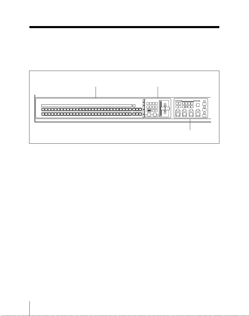
Program/Preset Bank
The program/preset (PGM/PST) bank
provides the final program output from the
switcher. Only the BKDS-7021, BKDS7022 and BKDS-7023 models (3.5-M/E
Signal selection section
(page 2-21)
PGM/PST
BLACK
PGM
BLACK
PST
PGM/PST bank (BKDS-7021/7022/7023)
panels) are equipped with this bank, and it
can only be used when the switcher system
has a DMK-7000 Digital Multi Keyer
connected.
Transition control section
(page 2-22)
Downstream keyer control
section (page 2-24)
2-20
Chapter 2 Location and Function of Parts
Page 53
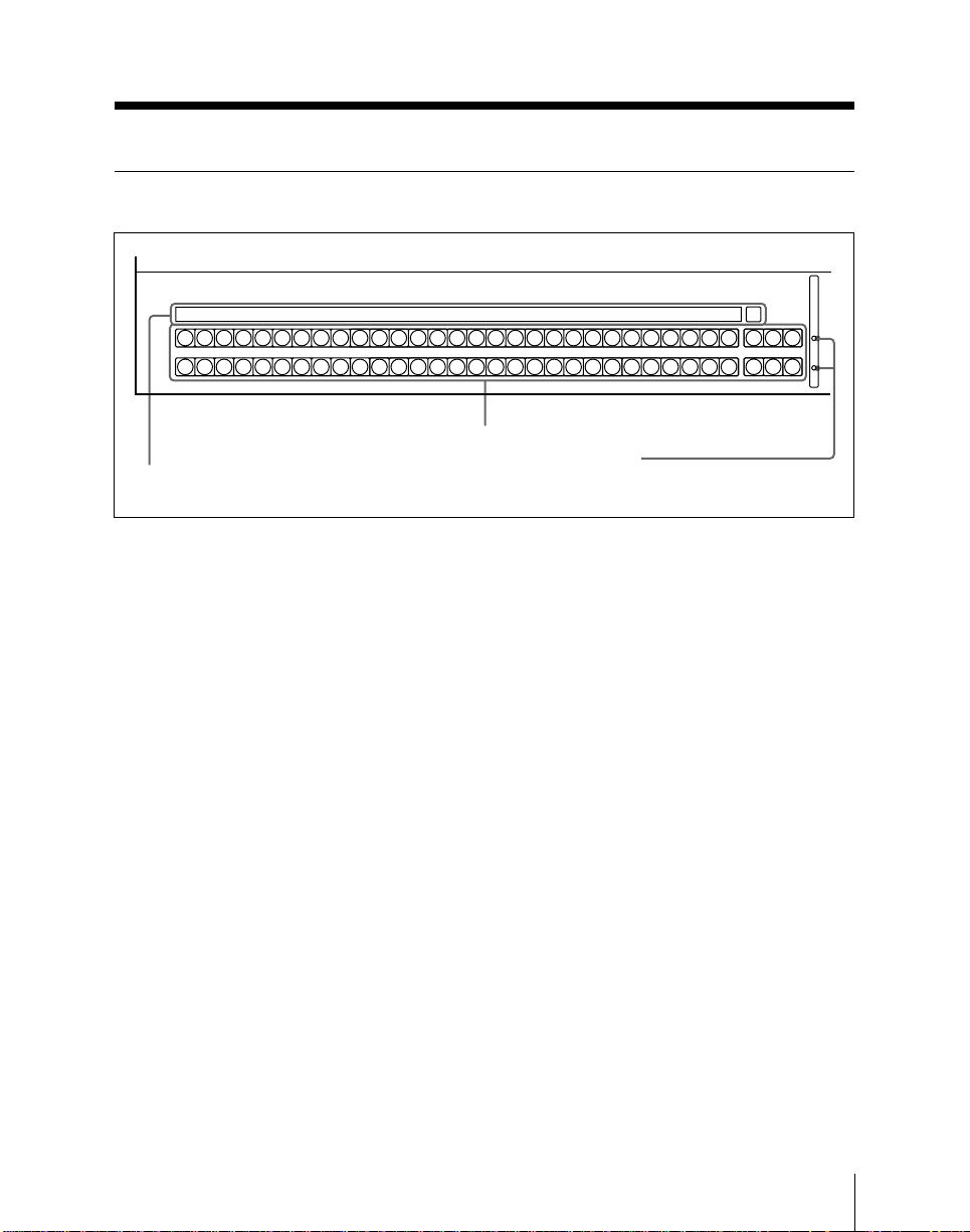
Signal Selection Section
BLACK
BLACK
3 Source name display
Signal selection section
1 Cross-point buttons
2 Bus tally indicators
SHIFT
COLOR
SHIFT
BKGD
COLOR
SHIFT
BKGD
M/E
M/E
M/E
3
2
1
M/E
M/E
M/E
3
2
1
1 Cross-point buttons
These buttons select the signals used for
video making on the PGM/PST bank.
The PGM (program) and PST (preset)
rows of buttons correspond to the A and B
buses of the M/E banks. Each row also
has three reentry buttons (M/E-1, M/E-2,
and M/E-3) to select the output from any
of the M/E banks.
PGM row: These buttons correspond to
the A row of an M/E bank. Except
while executing a background
transition, this bus provides the final
program output of the switcher.
PST row: These buttons correspond to
the B row of an M/E bank. This bus
provides the second background for a
transition, which replaces the
background currently on the program
bus.
The identifying numbers of the cross-point
buttons, and the visual indications are the
same as on the M/E banks.
For details, see pages 2-9 and 2-10.
2 Bus tally indicators
These have the same function as on the
M/E banks.
For details, see page 2-10.
3 Source name display
This has the same function as the source
name display on the BKDS-7011/7023.
For details, see page 2-10.
Chapter 2 Location and Function of Parts
2-21
Page 54
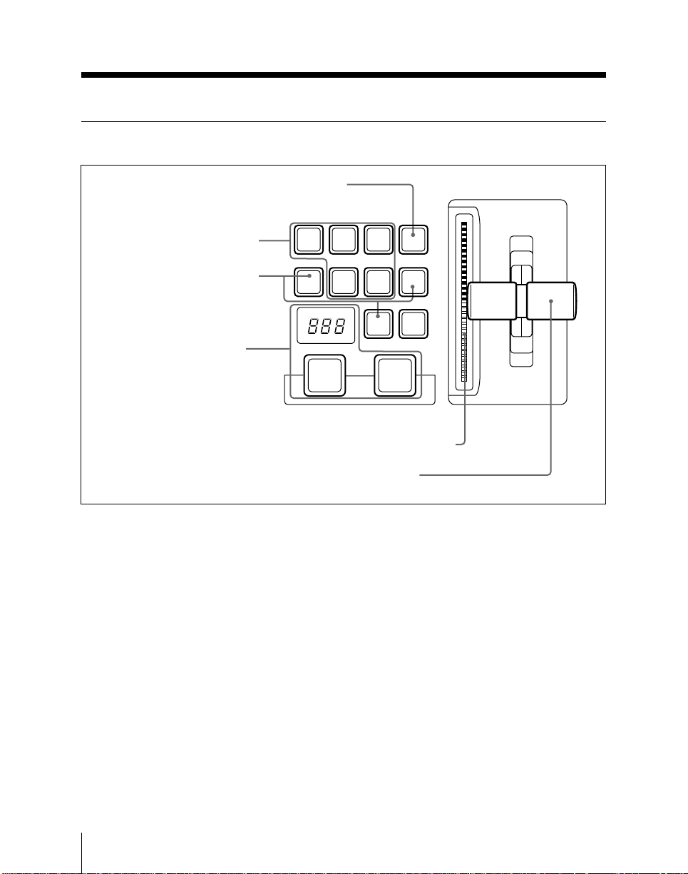
Program/Preset Bank
Transition Control Section
6 Programmable button
1 Next transition selection
buttons
2 Transition type selection
buttons
3 Auto transition control
section
BKGD
MIX
FRAMES
AUTO
TRANS
DSK1DSK
2
NEXT TRANSITION
DSK3DSK
TRANSITION TYPE
DME
WIPE
4
CUT
4 Transition indicator
5 Fader lever
1 Next transition selection buttons
These buttons determine what the next
transition will apply to.
DSK (downstream key) 1, DSK 2, DSK
3, DSK 4: Next transition will insert
or remove the corresponding
downstream key. If the key is
currently inserted it will be removed,
and vice versa.
BKGD: Next transition is a background
transition.
2-22
Chapter 2 Location and Function of Parts
Transition control section
You can press more than one of these
buttons simultaneously, and specify
different transition types for the different
transitions.
Page 55

2 Transition type selection buttons
Press one of these buttons, turning it on, to
determine the type of the next transition.
If you have specified different transition
types on this bank, all of these buttons
light.
MIX: The same as “MIX” on an M/E
bank. (See page 2-12.)
WIPE: Carry out a wipe, using the
settings in the wipe setting menu for
the PGM/PST bank.
DME: Selects a DME wipe (when a
DME-7000 or other Digital Multi
Effects unit is connected to the DMK-
7000).
• In addition to these buttons, to select the
DSK transition type, you can also use the
transition type selection buttons (MIX,
WIPE, DME) in the downstream keyer
control section.
• When you have selected a wipe or DME
wipe, you can also select the wipe
direction, using the wipe direction
selection buttons (NORM, NORM/REV,
REV) in the downstream keyer control
section.
3 Auto transition control section
This is the same as the auto transition
control section on an M/E bank.
4 Transition indicator
This has the same function as the
transition indicator on an M/E bank.
5 Fader lever
This has the same function as the fader
lever on an M/E bank.
6 Programmable button
By means of a setup menu, you can use
this button to light one or more of the next
transition buttons.
(Supported in version 6.10)
For more details, see “Changing switcher
functions (OPERATION MODE menu)”
(page 14-66).
Chapter 2 Location and Function of Parts
2-23
Page 56
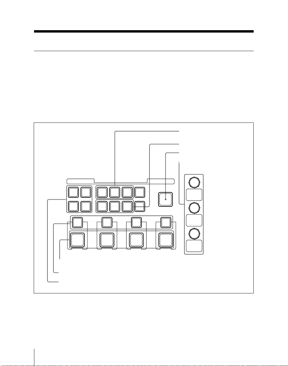
Program/Preset Bank
Downstream Keyer Control Section
The optional DMK-7000 Digital Multi
Keyer can incorporate a maximum of four
keyers. The buttons in the downstream
keyer control section select the keyer and
then control the key operations.
DOWNSTREAM KEYER
DSK
DSK
1
DSK3DSK
DSK1
ON
AUTO
TRANS
DSK1
MIX
2
NORM
4
DSK2
ON
AUTO
TRANS
DSK2
WIPE
NORM
REV
DME
REV
DSK3
ON
AUTO
TRANS
DSK3
On a BKDS-7011/7012 model with no
PGM/PST bank, fitting the optional
BKDS-7032 DSK control panel unit
provides the same functions as the
downstream keyer control section. The
BKDS-7032, however, has no key
parameter setting knobs and displays 7.
4 Transition type selection
buttons
5 Wipe direction selection buttons
6 FADE TO BLACK button
7 Key parameter setting
knobs and displays
FADE
TO
BLACK
DSK4
ON
AUTO
TRANS
DSK4
2-24
3 DSK 1 to DSK 4 AUTO TRANS buttons
2 Key insert/remove buttons
1 Keyer delegation buttons
Downstream keyer control section
Chapter 2 Location and Function of Parts
Page 57

1 Keyer delegation buttons
Press one of these buttons, turning it on, to
delegate the buttons in the downstream
keyer control section to the corresponding
keyer (DSK 1 to DSK 4).
Holding down any one of these buttons for
at least one second switches the AUX bus
bank to be the key fill bus for the keyer, so
that you can select the key signal. This
state remains as long as you hold down the
button.
2 Key insert/remove buttons
These buttons (instantaneously) cut the
respective keys in, or when the key is
already inserted, cut it out.
When the corresponding downstream key
is inserted in the output of the switcher
system, these buttons light red; when the
FADE TO BLACK button 6 is lit, they
light amber.
3 DSK 1 to DSK 4 AUTO TRANS
buttons
Pressing one of these buttons carries out
an auto transition on the respective
downstream key. The transition starts
immediately, and the button lights amber.
When the transition completes, the button
goes off.
While a transition is in progress (i.e. while
the button is lit amber), pressing the button
again pauses the transition, and the button
then lights green. Pressing the button
again in this state resumes the transition,
and the button reverts to amber.
You can set the transition duration using
the numeric keypad.
4 Transition type selection buttons
Press one of these buttons, turning it on, to
determine the type of the next transition.
MIX: This is the same function as a mix
(i.e. dissolve) on the M/E banks. (See
page 2-12.)
WIPE: The transition executed will be a
wipe, using the pattern selected in the
DSK WIPE menu.
DME: Carries out a DME wipe, using the
pattern selected in the P/P DME WIPE
menu. (when a DME-7000 or other
Digital Multi Effects unit is connected
to the DMK-7000).
• In addition to these buttons, you can also
use the MIX, WIPE and DME buttons in
the transition control section. (See page
2-23.)
• When you select a wipe or DME wipe,
you can also select the wipe direction
using the wipe direction selection buttons
5.
Chapter 2 Location and Function of Parts
2-25
Page 58

Program/Preset Bank
5 Wipe direction selection buttons
When you have selected a wipe or DME
wipe as the transition type, press one of
these buttons, turning it on, to select the
wipe direction.
NORM (normal) button: The wipe
proceeds in the direction from black to
white as shown on the wipe pattern in
the list of wipe patterns (page A-2)
and of DME wipe patterns (page A-8),
or in the direction of the arrow.
REV (reverse) button: The wipe
proceeds in the opposite direction to
that when the NORM button is
pressed.
NORM/REV (normal/reverse) button:
Alternate wipes go in normal and
reverse directions.
You can also use these three buttons and
the remaining two blank buttons as
programmable buttons, assigning PVW
SELECT functions.
For details, see “Changing switcher
functions (OPERATION MODE menu)”
(page 14-66).
7 Key parameter setting knobs and
displays
These have the same basic function as on
the M/E banks (see page 2-19), but the
parameters controlled are only clip, gain
and density. For other parameters, use the
DSK menu.
The optional BKDS-7032 DSK control
panel unit which can be fitted to the
BKDS-7011/7012 model, however, has no
key parameter setting knobs and displays.
On this control panel unit, use the DSK
menu for all parameter settings.
6 FADE TO BLACK button
Press this button, turning it on, to fade to
black. At the end of the transition, when
the video output is completely black, the
button lights red.
You can set the transition duration of the
fade-to-black, using a menu setting.
2-26
Chapter 2 Location and Function of Parts
Page 59
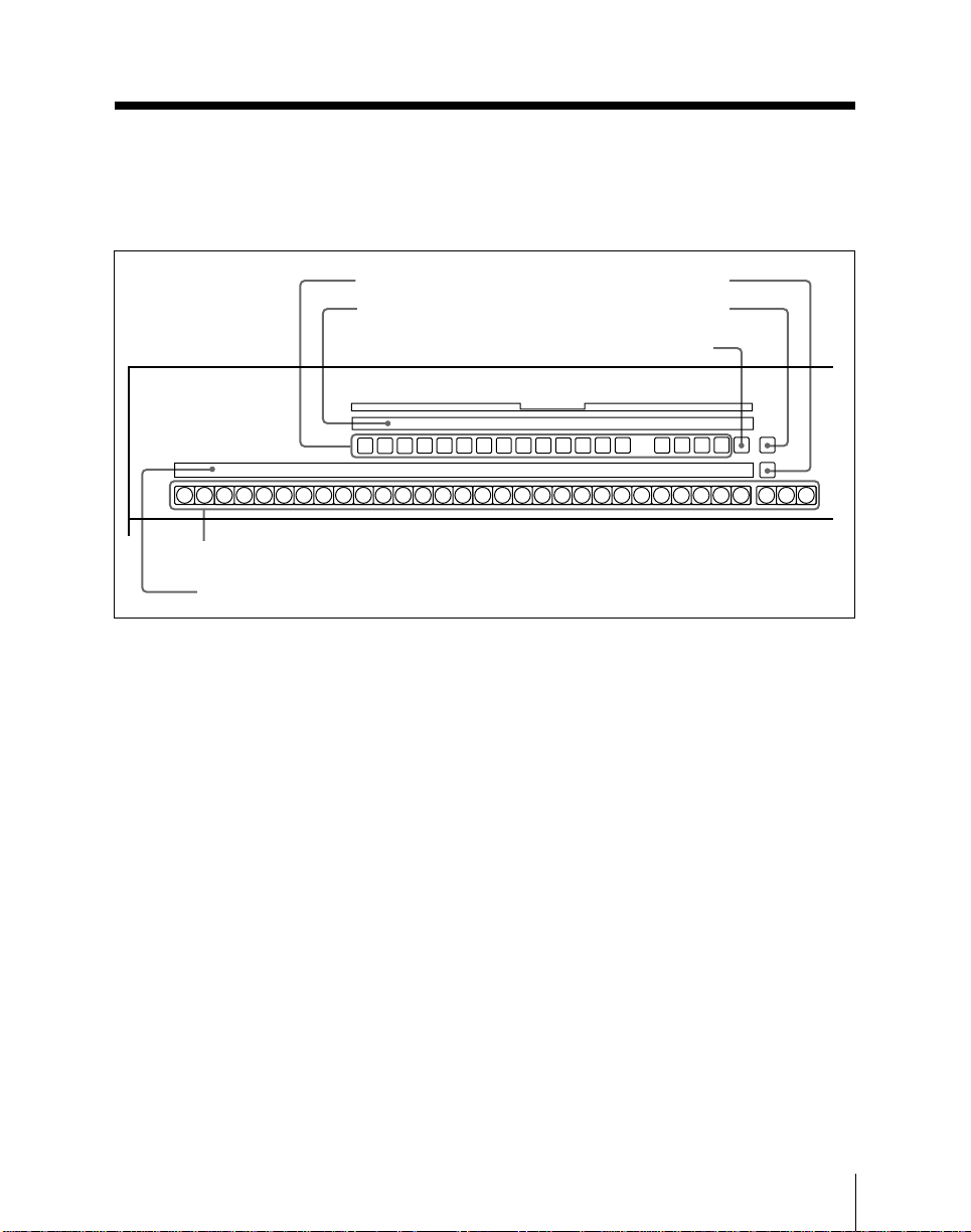
Auxiliary Bus Bank
The auxiliary bus bank controls the
selection of signals output from the unit,
and of signals used for video masking.
3 Delegation buttons
4 Selected signal display
AUX1AUX2AUX3AUX4AUX5AUX6AUX7AUX8AUX9AUX10AUX11AUX12AUX
BLACK
AUX
1 Cross-point buttons
2 Source name display
Auxiliary bus bank
1 Cross-point buttons
The leftmost 29 cross-point buttons in
each row are allocated to the same signals
as the cross-point buttons in the M/E
banks (and PGM/PST bank on the BKDS7021/7022/7023). At the right, there are
also three reentry buttons (M/E-1, M/E-2,
and M/E-3) to select the output from any
of the M/E banks.
The 29 buttons from the left act as buttons
numbered 0 to 28 when the SHIFT button
5 is not pressed. When the SHIFT button
is held down, these buttons select the
signals numbered 30 to 58. If, however, in
a setup menu you have allocated the 29th
button from the left as a shift button, then
the same operation as with the M/E crosspoint button is possible.
The cross-point buttons serve a total of 19
buses, including AUX 1 to AUX 13 and
the edit preview bus. Before selecting the
5 SHIFT button
6 Programmable
button
7 PV/K button
AUX DELEGATION
FRAME
FRAME
FDIT
PVW
13
M/E
MEM
MEM
1
V/K
UTIL
2
COLOR
SHIFT
M/E1M/E2M/E
SHIFT
BKGD
3
signal, delegate the cross-point buttons
with the appropriate delegation button 3.
2 Source name display
This displays the identifiers of the signals
which can be selected with the cross-point
buttons. When there are two signals
allocated to a cross-point button, hold
down the SHIFT button 5 to show the
identifiers assigned to the shifted buttons.
Holding down the shift button in the crosspoint button row also displays the
identifiers assigned to the shifted buttons.
If you are using the switcher and a DVS-B
series routing switcher connected by a
BKDS-7700, the signal names set on the
routing switcher can be displayed.
Chapter 2 Location and Function of Parts
2-27
Page 60

Auxiliary Bus Bank
3 Delegation buttons
Press one of these buttons, turning it on, to
delegate the cross-point buttons to the
corresponding bus.
AUX 1 to AUX 13 buttons: These
correspond to auxiliary buses 1 to 13.
The signals on these buses are output
from the connectors on the rear panel
labeled AUX BUS OUTPUTS 1 to 13.
EDIT PVW (preview) button: This
corresponds to the edit preview bus.
The signal on this bus is output from
the connector on the rear panel labeled
EDIT PVW OUTPUT.
FRAME MEM (memory) 1 and 2
buttons: These correspond to frame
memory buses 1 and 2. The signals
selected on these bases are input to
frame memory 1 and 2.
M/E UTIL button: This corresponds to
the utility buse for the three M/E
banks.
4 Selected signal display
This displays the identifier of the source
signal currently selected on each bus.
6 Programmable button
By means of a SETUP menu setting, you
can use this button for switching the
auxiliary bus bank between controlling the
auxiliary buses and controlling a routing
switcher, or for switching between
auxiliary buses 1 to 13 and auxiliary buses
14 to 28.
For details, see the section “Changing
switcher functions (OPERATION MODE
menu)” (page 14-66).
7 V/K button
Use this button when selecting the signal
assigned to an auxiliary bus at the key
level.
While this button is held down, in the
auxiliary bus bank the key signals on the
auxiliary bus selected by the delegation
button are displayed.
5 SHIFT button
Hold down this button and press a crosspoint button to select one of the signals
numbered 30 to 58. At this time the
identifiers assigned to the shifted buttons
are displayed.
2-28
Chapter 2 Location and Function of Parts
Page 61
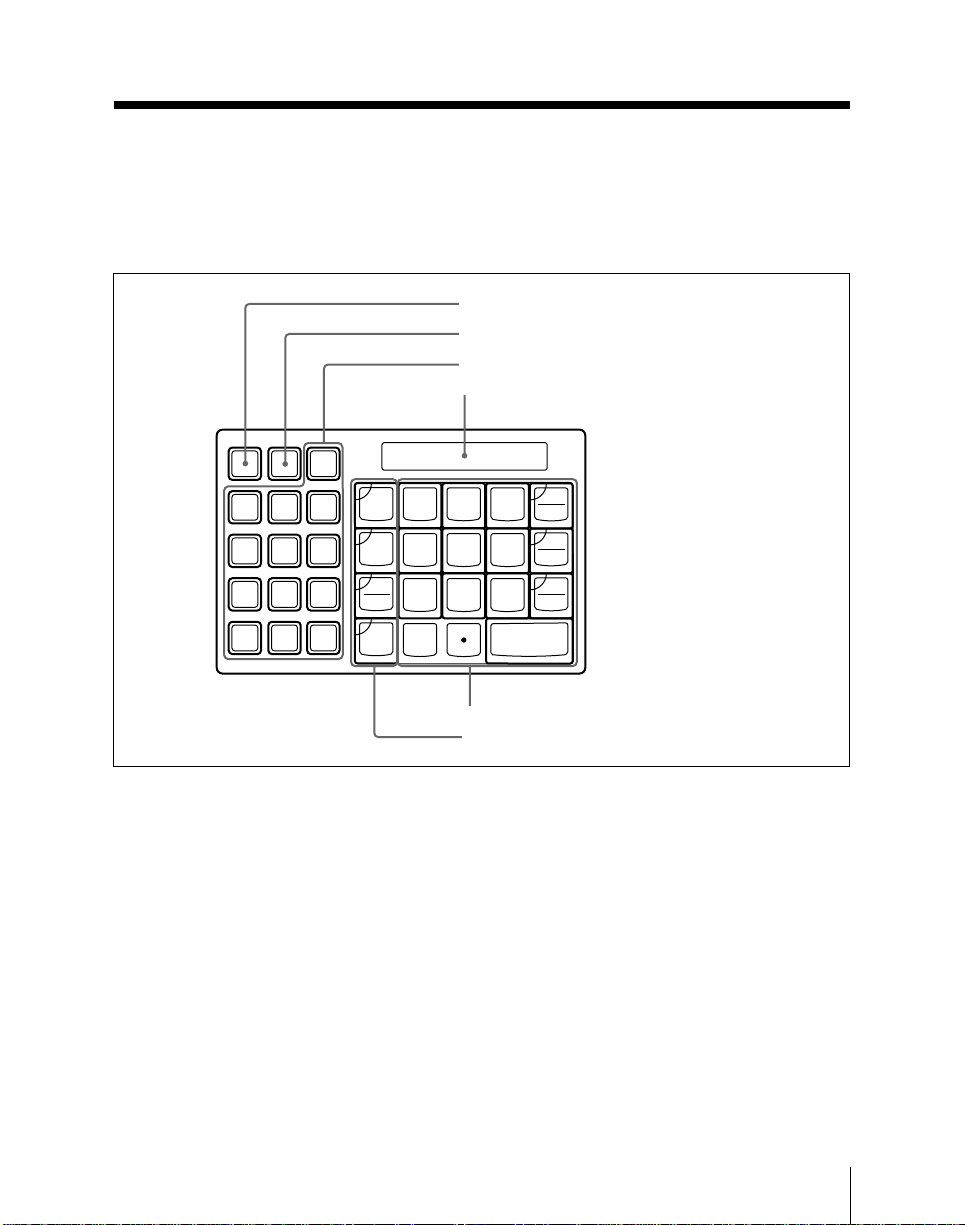
Numeric Keypad Section
The buttons in this section are used for
various numerical settings such as
transition durations, and for storing and
recalling snapshots and other values.
1 EFF button
2 SNAPSHOT button
3 Sub-register selection section
4 Display
SNAP
EFF ALL
SHOT
DME
USER
1
DME
2
DME
3
DME4DME
GLBL
DME
5
DME
6
TRANS
M/E
1
M/E
2
M/E
3
P/P
DSK
RATE
LASTX
STORE
LEARN
RCALL
7
4
1
0
9
8
5
6
2
3
ENTER
AUTO
TRANS
TRIM
XPT
DSBL
+/-
EFF
DIS
CLR
Numeric keypad section
1 EFF button
Press this button, turning it on, to save or
recall a key frame effect.
2 SNAPSHOT button
Press this button, turning it on, to save or
recall a snapshot.
3 Sub-register selection section
These buttons select the sub-registers to
which data save and recall operations
apply.
Sub-registers refer to subdivisions of a
register, and more than one can be selected
simultaneously.
5 Numeric keypad
6 Function selection buttons
Of the following buttons, the M/E 1, M/E
2, M/E 3, and P/P DSK buttons are also
used for selecting the bank to which a
transition rate setting applies.
ALL: Pressing this button selects all of
the following buttons.
It is possible to specify the buttons to
be selected when this button is
pressed.
For more details, see the section
“Changing switcher functions
(OPERATION MODE menu)” (page
14-66).
Chapter 2 Location and Function of Parts
2-29
Page 62

Numeric Keypad Section
M/E 1 to M/E 3 and P/P DSK: These
select the sub-registers corresponding
to the respective banks.
USER: This button selects the set of sub-
registers corresponding to the frame
memory, the auxiliary buses, and the
video processing function settings.
For snapshot registers, however, you
can select the USER button to control
any subset of these sub-registers,
using the REGISTER menu.
DME 1 to DME 6 and DME GLBL
(global): These buttons select the
DME units connected to the switcher
system.
4 Display
This shows entered numerical values, and
also the current function (for example
LEARN) or parameter name.
5 Numeric keypad
As well as numerical buttons, this also
includes buttons for applying attributes to
snapshots.
0 to 9: Input the corresponding digit.
“ . ”: Input a decimal point.
+/– /EFF DIS (effect dissolve): This
button inverts the sign of the value
being entered.
When the SNAPSHOT button 2 is
lit, this button has the effect of adding
the “EFFECT DISSOLVE” attribute
to the snapshot.
CLR/AUTO TRANS (clear/auto
transition): This clears an entered
value, and returns to the state before
starting input.
When the SNAPSHOT button 2 is
lit, this button has the effect of adding
the “AUTO TRANSITION” attribute
to the snapshot.
TRIM/XPT DSBL (cross-point disable):
Press this button instead of the
ENTER button if you wish to trim the
current setting, that is add the value
entered from the numeric keypad to its
current value.
When the SNAPSHOT button 2 is
lit, this button has the effect of adding
the “XPT DISABLE” attribute to the
snapshot.
ENTER: This confirms the value entered.
6 Function selection buttons
Use these buttons for setting the transition
duration, or for saving or recalling data in
registers.
TRANS (transition) RATE: Sets the
transition duration, thus determining
the rate at which it is carried out.
LAST X: Undoes a register recall
operation.
STORE/LEARN button: Saves a key
frame effect or snapshot in a register.
RCALL (recall) button: Recalls the
contents of a register.
2-30
Chapter 2 Location and Function of Parts
Page 63
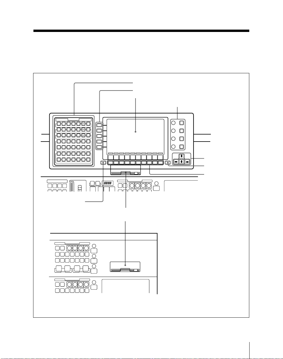
Menu Control Section and Floppy Disk
Drive
The menu control section provides a
variety of functions through the menu
screen.
1 Top menu selection buttons
2 Item selection buttons
3 Menu screen
4 Parameter setting section
TOP MENU
KEY1KEY
KEY1KEY
KEY1KEY
DSK
KEY
FRAME
BKGD
EDGE
NONLINEAR
CHR
WIPE
DME
KEY
1
M/E-1
CHR
WIPE
DME
KEY
1
M/E-2
CHR
WIPE
DME
KEY
1
M/E-3
P/P
FRAME
P/P
DSK
DSK
MEM
WIPE
WIPE
1
DME
STILL
DISK
REGS
MISC
FILE
SYSTEM
FREZE
PIC
VIDEO
IN
MOD
RECUR
MOD
OUT
DME DME
LIGHT
GRAPH
STATS SETUP
EFF
UTILITY
8 SHIFT button
KEY CONTROL
KEY CONTROL
BKGD
TRANS
1
BKGD
TRANS
2
BKGD
TRANS
3
FRAME
STATS
MEM
4
2
DIAG
5
SETUP
SHIFT
F1 F2 F3 F4 F5 F6 F7 F8 F9 F10
KEY
PAD
KEY
PAD
KEY
PAD
KEY
PAD
EXIT
5 Cursor keys
6 EXIT button
7 Function keys
KEY CONTROL
9 Floppy disk drive (BKDS-7011/7012)
9 Floppy disk drive (BKDS-7021/7022/7023)
Menu control section and floppy disk drive
Chapter 2 Location and Function of Parts
2-31
Page 64

Menu Control Section and Floppy Disk Drive
1 Top menu selection buttons
Each of these buttons accesses a top menu.
For details of the menu names and
functions associated with these buttons,
see page 3-2.
2 Item selection buttons
These five buttons select the items within
a menu. Pressing a button highlights the
item display in reverse video, and changes
the function key indications accordingly.
3 Menu screen
This displays the menu currently in use.
For detailed menu operation, see Chapter
3.
4 Parameter setting section
The controls in this section correspond to
the values of parameters represented by
bar indications at the right side of the
menu screen.
Knobs: Turning a knob adjusts the value
directly. In this manual these are
referred to as knobs 1 through 4 from
the top down.
KEY PAD buttons: Pressing one of these
buttons allows you to enter the
corresponding parameter value from
the numeric keypad.
6 EXIT button
Press this button to exit from the currently
displayed menu to its parent menu, or the
previously displayed menu. When a popup appears in the menu screen, this button
also clears the pop-up.
7 Function keys
Function keys F1 to F10 carry out the on/
off or selection operations shown by the
function key indications along the lower
edge of the menu screen.
If there are two indications for a single
function key, hold down the SHIFT button
and press the function key to obtain the
effect of the upper indication.
8 SHIFT button
Use this in conjunction with the function
keys F1 to F10 7 and item selection
buttons 1 to 5 2.
9 Floppy disk drive
This takes a 3.5-inch floppy disk. You use
it for installing the operation software, and
for saving snapshot, key frame, setup and
other data on a floppy disk.
The disk drive is controlled by menu
operations.
5 Cursor keys
Press these to change the group of
parameters being adjusted, and also to
move the cursor about the menu screen.
2-32
Chapter 2 Location and Function of Parts
Page 65
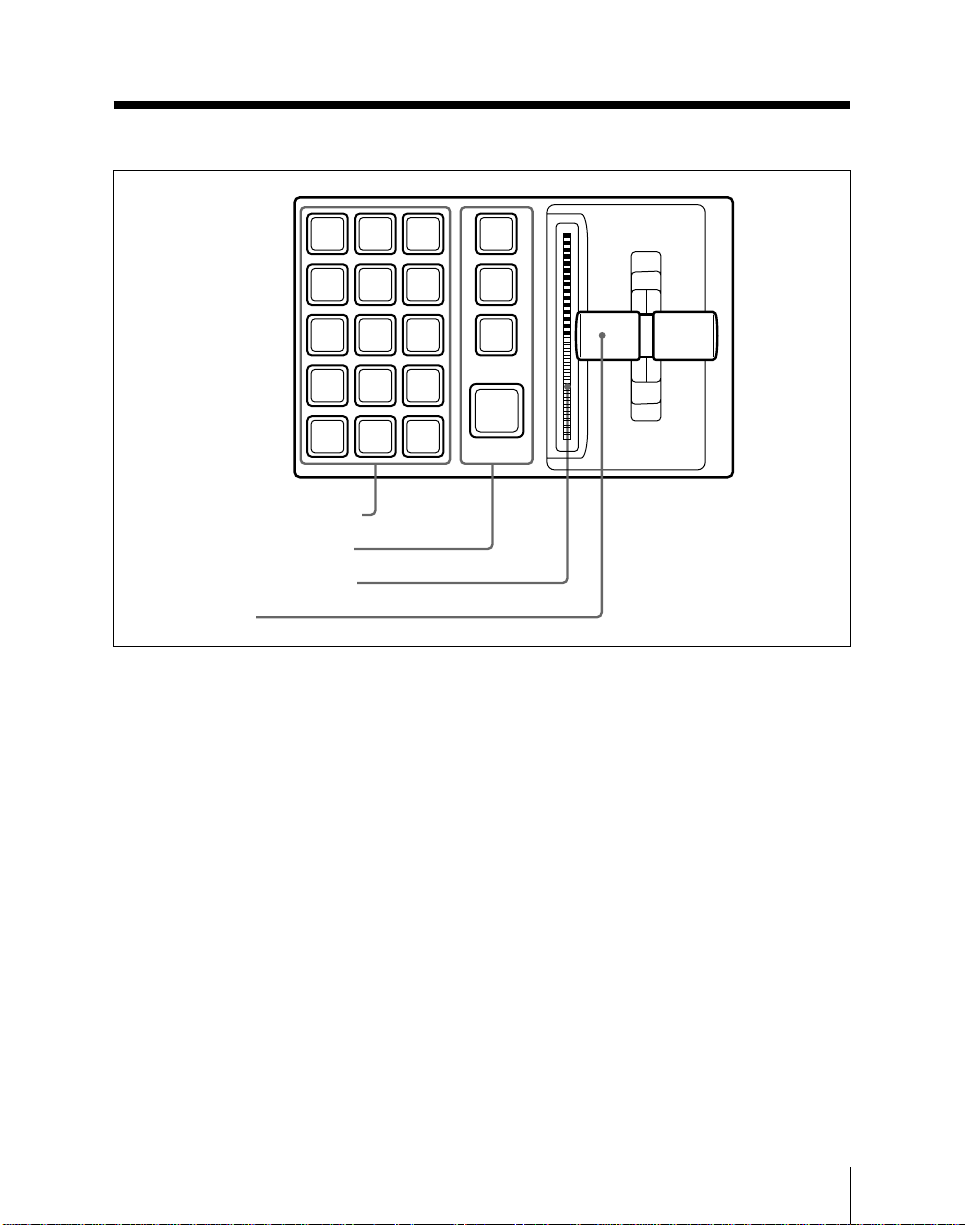
Key Frame Control Section (BKDS-7030
Key Frame Control Panel Unit – Option)
EDIT
EFF
ENBL
DURKFDUR
COPY
PASTE DELAY REV
FROM
MOD
INS
SHIFT
DEL
TO
GO
GO
TO
TO
TC
KF
PREVKFNEXT
KF
1 Key frame editing section
2 Effect execution section
3 Effect progress indicator
4 Fader lever
Key frame control section
1 Key frame editing section
EDIT ENBL (enable) button: Pressing
this button, turning it on, enables the
creation and editing of key frames (edit
mode). Regardless of the setting of
this button, however, while an effect is
being executed it is not possible to
create or edit effects.
EFF DUR (effect duration) button:
Press this button to set the effect
duration (the overall length of the
effect) using the numeric keypad.
STOP
NEXT
KF
RE
WIND
RUN
KF DUR (key frame duration) button:
Press this button to set the key frame
duration (the time from the current key
frame to the next key frame) using the
numeric keypad.
COPY button: This copies the current
key frame into the paste buffer. It can
then be inserted using the PASTE
button.
If a range is specified with the FROM
TO button, all key frames in this range
are copied together into the paste
buffer.
Chapter 2 Location and Function of Parts
2-33
Page 66

Key Frame Control Section (BKDS-7030 Key Frame Control Panel
Unit – Option)
PASTE button: Pressing this button
inserts the key frame from the paste
buffer into the current position where
the effect is stopped.
If the effect is stopped at a key frame,
the insertion point is determined as
follows.
• When this button only is pressed, the
insertion is immediately after the
current key frame.
• When this button is pressed with the
SHIFT button held down, the
insertion is immediately before the
current key frame.
DELAY button: Press this button to set
the delay from the position of the first
key frame to the start of the effect
using the numeric keypad.
MOD (modify) button: Writes the
current working key frame buffer to
the current key frame. When the effect
is stopped between frames, the
immediately previous key frame is
rewritten.
If a range is specified with the FROM
TO button, all key frames in this range
are rewritten together.
FROM TO button: To copy, delete, or
modify a number of key frames
together, first press this button, and
input the key frame numbers to specify
a range.
DEL (delete) button: This deletes the
current key frame. When the effect is
stopped between frames, the
immediately previous key frame is
deleted. If a range is specified with the
FROM TO button, all key frames in
this range are deleted.
INS (insert) button: While the effect is
stopped, this inserts a new key frame.
If the effect is stopped at a key frame,
the insertion point is determined as
follows.
•When this button only is pressed, the
insertion is immediately after the
current key frame.
•When this button is pressed with the
SHIFT button held down, the
insertion is immediately before the
current key frame.
GO TO TC (time code) button: Press
this button, then enter a time code
value from the numeric keypad, to go
to that time code position.
GO TO KF (key frame) button: Press
this button, then enter a key frame
number from the numeric keypad, to
go to that key frame.
SHIFT button: Holding down this button
changes the effect of the INS and
PASTE buttons.
PREV KF (previous key frame)
button: Moves back to the last key
frame before the current position.
NEXT KF (key frame) button: Moves
forward to the next key frame after the
current position.
2-34
Chapter 2 Location and Function of Parts
Page 67

2 Effect execution section
STOP NEXT KF (key frame) button:
When this button is lit, effect execution
continues up to the next key frame.
REV (reverse) button: When this button
is lit, effect execution occurs in the
reverse direction.
REWIND button: This rewinds to the
first key frame of the currently recalled
effect. If the REV button is on,
however, this moves to the last key
frame.
RUN button: Executes the effect from
the first key frame to the last key
frame. If, however, a pause time point
is set at some point during the effect,
the execution stops when it reaches this
point.
Pressing this button while the effect is
being executed stops execution, and
pressing it again resumes execution.
3 Effect progress indicator
The lit portion of the indicator shows the
state of progress of the effect.
4 Fader lever
Use this for manual execution of an effect.
Chapter 2 Location and Function of Parts
2-35
Page 68
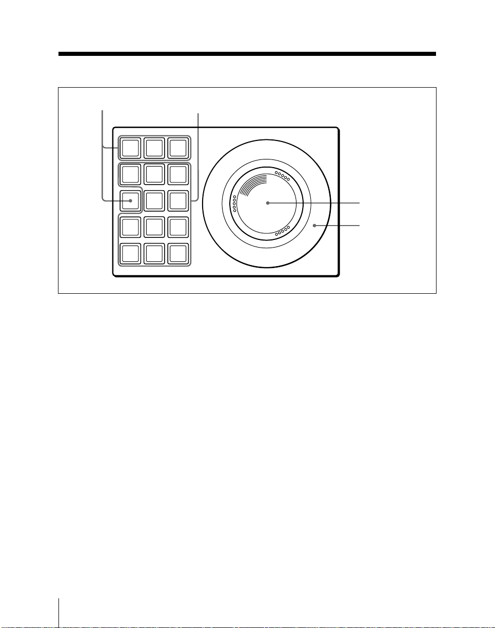
DME Control Section (BKDS-7031 DME
Control Panel Unit – Option)
1 Function allocation
buttons
MENU SRCE TRGT
LOC
ASP
SKEW
SIZE
PERS
AXIS
ORTHG
LOC
XYZ
CLR
WORK
CTR
BUFR
2 Operating buttons
LOC
XYZ
ROT
VELO
HOLD
DME control section
In addition to DME operations, the
optional DME control panel unit can be
used for wipe pattern positioner operations
on the switcher and VTR tape transport
control.
1 Function allocation buttons
Allocate the overall functions of the DME
control panel as follows.
SRCE (source): Allocate to operations in
the DME source coordinate system.
TRGT (target): Allocate to operations in
the DME target coordinate system.
For details of the effect of controls 2 to
4 when the SRCE or TRGT button is
pressed and lit, refer to the BZDM-7720/
3720 User’s Guide.
3 Trackball
4 Z-ring
MENU: Allocate to knob operations in the
menu control section. This button also
lights when allocated to the wipe
pattern positioner.
ORTHG (orthogonal or VTR control):
Allocate to VTR tape transport control.
To use the ORTHG button for tape
transport control, in the setup menus a
setting is necessary for using this
button as a VTR button. For details,
see the section “Changing switcher
functions (OPERATION MODE
menu)” (page 14-66).
When the setting to use this button as a
VTR button is not made, this button
functions as one of the operating
buttons 2.
2-36
Chapter 2 Location and Function of Parts
Page 69

For details of the effect of controls 2 to
4 when the MENU or ORTHG button is
pressed and lit, see below.
Effect of controls 2 to 4 when the
MENU button is lit
2 Operating buttons
ASP SKEW PERS (M/E-1): Functions as
the M/E-1 button, allocated to M/E-1
operations on the DME control panel.
LOC SIZE (M/E-2): Functions as the M/
E-2 button, allocated to M/E-2
operations on the DME control panel.
LOC XYZ (M/E-3): Functions as the M/
E-3 button, allocated to M/E-3
operations on the DME control panel.
AXIS LOC (REV): When the ASP
SKEW PERS (M/E-1), LOC SIZE (M/
E-2) or LOC XYZ (M/E-3) button is
lit, functions as a REV (reverse) button
for wipe operations on the
corresponding bank. When this is
“ON”, wipe transitions occur in the
reverse direction. When it is “OFF”,
wipe transitions occur in the forward
(“normal”) direction.
ROT (POS): When the ASP SKEW PERS
(M/E-1), LOC SIZE (M/E-2) or LOC
XYZ (M/E-3) button is lit, toggles on
or off the main pattern wipe positioner
function on the corresponding bank.
X, Y, Z: The X and Y buttons enable
movement of the trackball in the x- and
y-directions. The Z button enables
operation of the Z-ring. If all three
buttons are off, the X, Y, and Z
directions are all enabled; that is, this is
the same as when all three buttons are
lit.
CLR WORK BUFR: Not used.
CTR (center): When the ASP SKEW
PERS (M/E-1), LOC SIZE (M/E-2) or
LOC XYZ (M/E-3) button is lit,
returns the wipe pattern to the default
position on the corresponding bank.
VELO HOLD (velocity hold): If you
hold down this button while
manipulating the trackball or Z-ring,
then when you release the trackball or
Z-ring the function continues at the
same velocity as long as the button is
held down.
ORTHG (when not used as a function
allocation button 1): When this
button is lit, moving the trackball
produces an orthogonal effect, moving
only in whichever of the x- and ydirections has the larger component.
3 Trackball
Horizontal movement (X) is allocated to
the control of knob 1, and vertical
movement (Y) to the control of knob 2.
When the ASP SKEW PERS (M/E-1),
LOC SIZE (M/E-2) or LOC XYZ (M/E-3)
button is lit, functions as the wipe
positioner on the corresponding bank.
4 Z-ring
Allocated to the control of knob 3. When
the auto chroma key sample mark
adjustment menu is displayed, this is used
to adjust the size of the sample mark.
Chapter 2 Location and Function of Parts
2-37
Page 70

DME Control Section (BKDS-7031 DME Control Panel Unit – Option)
To keep the knob controls allocated
to the trackball and Z-ring
With the knob controls allocated to the
trackball and Z-ring, press the MENU
button twice in rapid succession. The
MENU button lights green, and even if
you change to another menu, the allocation
of the trackball and Z-ring remains
unchanged.
To end this allocation, press the SRCE,
TRGT, or ORTHG (VTR) button.
Effect of controls 2 to 4 when the
ORTHG (VTR) button is lit
2 Operating buttons
ASP SKEW PERS (MARK IN): Saves
the current timecode as the start point.
LOC SIZE: Not used.
LOC XYZ (MARK OUT): Saves the
current timecode as the stop point.
AXIS LOC: Not used.
ROT: Not used.
X (REW): Rewinds the tape.
Y (PLAY): Plays back the tape.
Z (FF): Fast forwards the tape.
CLR WORK BUFR (STB OFF):
Switches to “standby off” mode.
CTR (STOP): Stops the tape.
VELO HOLD (JOG): Moves the tape at
a speed dependent on the rate of
rotation of the search dial (jog mode).
3 Trackball
Not used.
4 Z-ring
In jog mode, acts as a search dial.
2-38
Chapter 2 Location and Function of Parts
Page 71
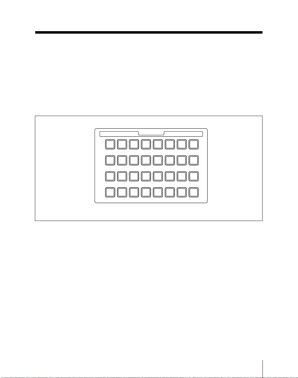
SHOT BOX Control Section (BKDS-7033
Memory Recall Control Panel Unit – Option)
This section executes the function
preassigned using a setup menu.
(UTILITY buttons)
You can assign registers storing such data
as snapshots and key frame effects to these
buttons so that you can recall them by
pressing the corresponding buttons.
(Shot box function)
1 2 3 4 5 6 7 8
9 10 11 12 13 14 15 16
17 18 19 20 21 22 23 24
25 26 27 28 29 30 31 32
SHOT BOX control section
For more information, see the section
“Assigning functions to the UTILITY
buttons (UTILITY menu)” (page 14-86).
SHOT BOX
Chapter 2 Location and Function of Parts
2-39
Page 72

Page 73

Chapter 3
Basic Menu Operations
Menu Organization ................................................................................... 3-2
Basic Menu Operations ............................................................................. 3-6
Page 74

Menu Organization
Operations on the DVS-7300/7350 I/O expansion system make frequent use
of menu operations. This section describes the menus and their
interrelationships.
Overview
All detailed settings for basic operations such as transitions, keys, or wipes,
are made in menus. There are also menus for carrying out general system
control, managing setting data, and initial setup.
Accessing menus
There are two ways to access a menu, and the initially selected items (1 to 5)
depend on the method used.
• Pressing a top menu button in the menu control section.
This always returns to the selection when you last accessed this particular
menu.
After initially powering on the system, however, item 1 is always selected.
• Pressing a button other than a top menu button twice in rapid succession.
Depending on the menu, this may select a fixed item or the item selected
last time you accessed the menu.
For details of the menu items, see page 3-6.
Menus and their functions
Menus accessed from a top menu button
The menus which can be accessed from a top menu button are listed in the
following table, together with their functions.
3-2
Chapter 3 Basic Menu Operations
Page 75

Menus accessed from a top menu button
Group Menus Function
M/E-1,
M/E-2,
M/E-3
Button
KEY1, KEY2
M/E-1, -2, -3
KEY1 or KEY2
WIPE M/E-1, -2, -3
Key 1 and key 2 settings for the M/E bank
Wipe settings for the M/E bank
See page
4-47
4-103
WIPE
DME M/E-1, -2, -3
DME wipe settings for the M/E bank
4-132
DME WIPE
CHR KEY M/E-1, -2, -3
Chroma key settings for the M/E bank
5-4,5-18
CHROMA KEY
BKGD/
TRANS
SYSTEM DSK DSK1, 2, 3, 4
DSK WIPE DSK 1, 2, 3, 4
M/E-1, -2, -3
BKGD/TRANS
Color background, transition limit and other
settings for the M/E bank
Settings for the four downstream keys
Downstream key wipe settings
a)
a)
4-142
4-72
4-117
WIPE
P/P WIPE PGM/PST
WIPE
P/P DSK
DME
P/P DSK DME
WIPE
Wipe and color background settings for the
PGM/PST bank
DME wipe settings for PGM/PST
backgroundb) and downstream key
b)
a)
4-116
4-133
transitions
STATS STATUS Displaying the status of each bank
FRAME MEM
1, 2
FRAME
MOMERY 1, 2
Settings for the two frame memories
4-144
6-6
STILL FILE STILL FILE Settings for saving and recalling still images 6-18
KEY FRAME KEY FRAME Key frame operation and editing
REGS REGISTER Managing registers holding snapshots and
8-32
9-6
other data
DISK DISK Floppy disk operations 10-5
MISC MISC Miscellaneous operations including control by
12-2
external equipment, safe title display, the
video process function, and the color
correction function
SETUP SETUP Setup functions
DIAG
DIAGNOSIS Displaying the board configuration and
14-3
15-2
adjusting analog output signals
UTILITY The buttons in this group access the menus assigned to them using a setup
14-86
menu.
a) This function is only available in a 3.5-M/E system or a 3-M/E system equipped with a downstream
keyer.
b) This function is only available in a 3.5-M/E system.
Chapter 3 Basic Menu Operations
3-3
Page 76

Menu Organization
Menus accessed by pressing a button twice
For certain buttons other than the top menu buttons, pressing twice in rapid
succession directly recalls a related menu. The following table lists these
buttons, together with the menus they recall.
Items listed in parenthesis after the menu names are automatically selected
when the menu is recalled. If no item is shown, the item you last selected in
this menu is automatically selected.
Menus accessed by pressing a button twice
Button location Buttons Menus See page
Transition control
section of M/E-1,
M/E-2, or M/E-3
bank
Key control section
of M/E-1, M/E-2, or
M/E-3 bank
Transition control
section of PGM/
PST bank
(3.5-M/E panels)
Downstream keyer
control section
(3.5-M/E panels,
and 3-M/E panels
with a BKDS-7032
fitted)
a) The menu recalled depends on which of keyers 1 and 2 the key control section is delegated to.
b) The menu recalled depends on which of the downstream keys (DSK1 to DSK4) the downstream
keyer control section is delegated to.
KEY1, KEY2 M/E-1, -2, -3 KEY1 or KEY2 4-47
WIPE M/E-1, -2, -3 WIPE 4-103
DME M/E-1, -2, -3 DME WIPE 4-132
SUPER MIX M/E-1, -2, -3 BKGD/TRANS (item 2: LIMIT/S-MIX) 4-20
KEY1, KEY2 M/E-1, -2, -3 KEY1 or KEY2 4-47
CHR M/E-1, -2, -3 CHROMA KEY 5-4,5-18
PTN M/E-1, -2, -3 WIPE 4-103
LUM, LIN,
CLEAN
AUTO SEL,
SPLIT
DSK1, DSK2,
DSK3, DSK4
WIPE PGM/PST WIPE 4-116
DME P/P DSK DME WIPE 4-133
DSK1, DSK2,
DSK3, DSK4
WIPE DSK1, DSK2, DSK3 or DSK4 WIPE
DME P/P DSK DME WIPE 4-133
M/E-1, M/E-2, M/E-3 KEY 1 or KEY 2
(item 1: TYPE)
M/E-1, M/E-2, M/E-3 KEY 1 or KEY 2
(item 2: FILL/SOURCE)
DSK1, DSK2, DSK3, DSK4 4-72
DSK1, DSK2, DSK3, DSK4 4-72
a)
a)
b)
4-47
4-51
4-117
3-4
(Continued)
Chapter 3 Basic Menu Operations
Page 77

Menus accessed by pressing a button twice (Continued)
Button location Buttons Menus See page
Cross-point button
in M/E-1, M/E-2,
M/E-3 or PGM/PST
bank (3.5-M/E
panels) to which
the signal indicated
in “Buttons” column
is assigned
Numeric keypad
section
Auxiliary bus bank AUX1 to AUX13
FlexiPad in M/E-1,
M/E-2 or M/E- 3
Color
background
signal (M/E
banks)
Color
background
signal (PGM/
PST bank)
Frame momory
1 or 2 signal
Chroma key fill
1, 2, or 3 signal
EFF REGISTER (item 1: EFFECT) 9-6
SNAPSHOT REGISTER (item 2: SNAPSHOT) 9-6
TRANS RATE STATUS (item 5: ALL) 4-146
EDIT PVW
DME, WIPE,
SNAPSHOT
M/E-1, M/E-2, M/E-3 BKGD/TRANS
(item 1: COLOR BKGD)
PGM/PST WIPE (item 5: COLOR BKGD) 4-143
FRAME MEMORY 1 or 2 6-6
M/E-1, -2, -3 CHROMA KEY 5-4,5-18
STATUS (item 5: ALL)
STATUS (item 1: M/E-1), (item 2: M/E-2), (item 3:
M/E-3)
4-142
4-144
4-148 to
4-150
Chapter 3 Basic Menu Operations
3-5
Page 78
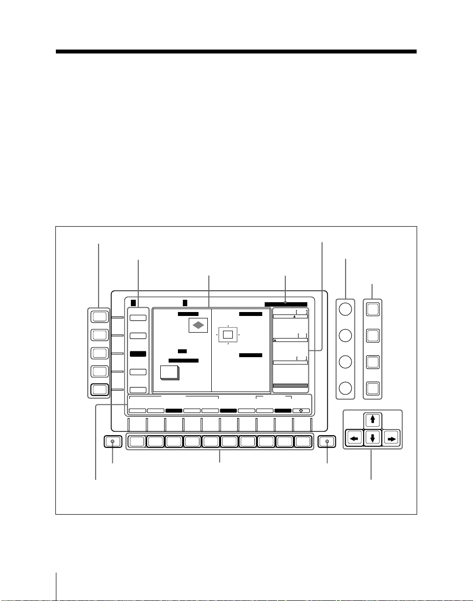
Basic Menu Operations
This section describes the basic menu operations, taking the M/E-1 KEY 1
menu as an example.
Accessing the menu
To access the M/E-1 KEY 1 menu, use either of the following operations.
• In the M/E-1 group of the top menu buttons, press the KEY 1 button.
• In the transition control section of the M/E-1 bank, press the next transition
selection button KEY 1 twice in rapid succession.
• In the key control section of the M/E-1 bank, press the keyer delegation
button KEY 1 twice in rapid succession.
The M/E-1 KEY 1 menu appears as shown in the following figure.
Item selection buttons (1 to 5)
Items (1 to 5)
M/E-1 KEY 1
TYPE
1
2
3
4
5
SHIFT
KEY TYPE
KEY INV :OFF
FILL/
SOURCE
FULL :
SOURCE
EDGE
PROC KEY
EDGE
MAIN
MASK
SUB
SOFT EDGE :OFF
MASK
NORMAL
BORDER
F1 F2 F3 F4 F5 F6 F7 F8 F9 F10
SHIFT button
Function key
indications
Parameter indications
4H
DROP
ON
KEY MASK
:
:OFF
: BOX
KEY MASK
:
:OFF
: UTIL BUS
SOFT
EDGE
OFF
Parameter group
name
DROP BORDER
Width
0
Position
1
Density
0
100.00
EDGE FILL
UTILITY
MATTE
BUS
Setting display
PATTERN
:
:
:
ON
DROP BORDER
:
EDGE FILL :
MIX MATTE
EDGE TYPE
DROP
SHADOW
BORDER
LINE
OUT
MAIN MASK
SUB MASK
MASK INVERT
MASK SOURCE
MASK INVERT
MASK SOURCE
Function keys
Menu display and menu control section
(1/2)
Lum
8
5
Sat
8
0
Hue
100
MATTE
ADJUST
EXIT button
Control knobs
EXIT
KEY PAD
buttons
KEY
PAD
KEY
PAD
KEY
PAD
KEY
PAD
Cursor
movement
buttons
3-6
Chapter 3 Basic Menu Operations
Page 79

Understanding the menu display
The following are the principal components of the menu display.
In the menu display, reverse video indicates that an item or function is
currently selected (or set to “on”).
Items: These are the items to which the menu settings apply. Depending on
the item selected, the menu display and function key indications change.
In the example shown, item 3 “EDGE” is selected, and settings and
function key indications relating to edge settings appear. In this manual,
the menu display when a particular item is selected is sometimes referred
by the name of the item: for example, the EDGE menu.
Setting display: This shows current settings. In the example shown,
“DROP BORDER” is selected as the edge type.
Parameter group name: The set of parameters associated with the function
for a particular function key is termed a “parameter group”.
In the example shown, the “DROP BORDER” parameter group is
selected. Note that where there are five or more parameters in the same
group, either “(1/2)” or “(2/2)” is appended to the group name.
Parameter indications: These show the current values of the parameters
adjusted with the four control knobs.
In the example shown, the values for three of the “DROP BORDER”
parameters appear. In total the “DROP BORDER” group has seven
parameters, and the names of those not currently displayed appear in
brackets (e.g. “[Lum]”, for luminance).
Function key indications: These indicate the operations carried out by the
respected function keys.
To select an item
Press the corresponding one of the item selection buttons (numbered 1 to 5).
The function key indications change, and you can now make the relevant
settings.
Chapter 3 Basic Menu Operations
3-7
Page 80
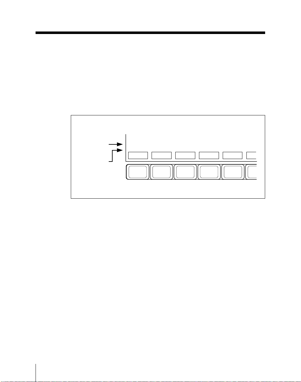
Basic Menu Operations
To select a function
Press the corresponding function key.
In this manual, for example in the M/E-1 KEY 1 menu shown on page 3-6
pressing F3 to select the “DROP BORDER” function is indicated simply by
“Press F3 (DROP BORDER)”.
In the figure on page 3-6 there is a single row of function key indications, but
in some menus two rows appear.
Functions for
F11 and F12
Functions for
F1 to F10
[FORMAT]
SAVE
F1 F2 F3 F4 F5
To select the upper row of functions (indicated as F11 to F20), hold down the
SHIFT button to interchange the two rows of indications, then press the
corresponding function key F1 to F10.
To return to the previous menu
To return to the menu displayed before the current menu, press the EXIT
button.
Moving the cursor
In wipe pattern selection and SETUP menu screens, a cursor appears. To
move the cursor press one of the cursor movement buttons (M m < ,).
[LABEL]
LOAD
COPY
DELETE
RENAME
3-8
Chapter 3 Basic Menu Operations
Page 81
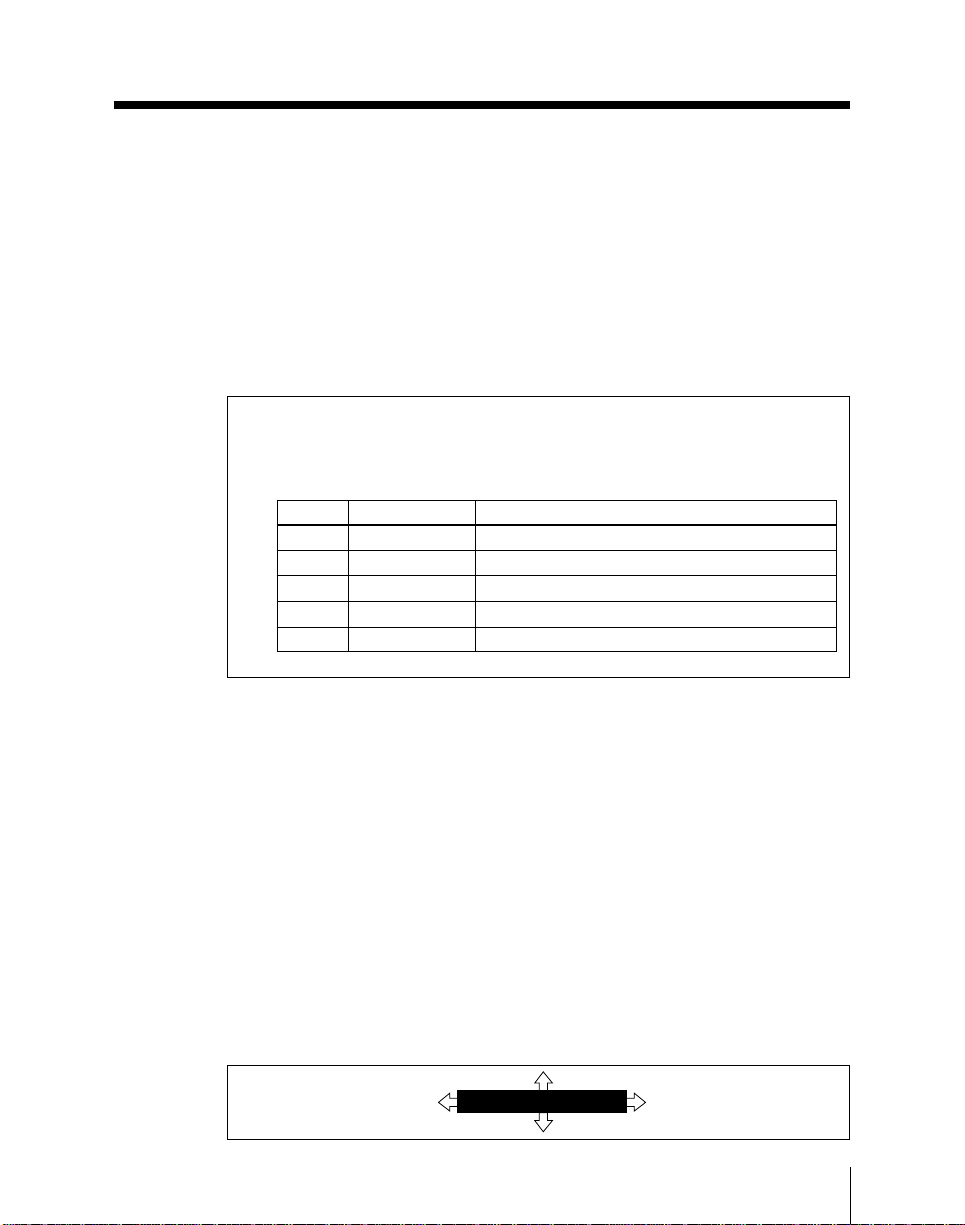
Setting parameter values
You can change a currently displayed parameter in either of the following
ways.
• Turn the one of the four control knobs corresponding to the parameter.
• Press the KEY PAD (1 to 4) button corresponding to the parameter, then
enter the new value using the numeric keypad section.
The following is a concrete example showing adjustment using the control
knobs, as a typical case.
4 Adjust the parameters.
When you have selected a box:
Knob Parameter Setting
1 Top Top edge position (0.00 to 100.00)
2 Left Left edge position (0.00 to 100.00)
3 Right Right edge position (0.00 to 100.00)
4 Bottom Bottom edge position (0.00 to 100.00)
1 Softness Set the degree of edge softness (0.00 to 100.00)
Changing the parameter group
When more than one parameter group is shown, to display the parameters in
a different group, press the corresponding function key or the cursor < or
, button. Again, when there are five or more parameters in the same group,
as shown in the example above, to display different parameters, press the
cursor M or m button.
In the example, when the parameters “Top”, “Left”, “Right”, and “Bottom”
are displayed, press the M or m button to change to the “Softness” parameter.
You can then adjust the edge softness with control knob 1.
The arrows in icons appearing on the menu screen, as shown below, indicate
which cursor buttons can be used.
In the example below, the vertical arrows indicate that the cursor M and m
buttons toggle between the 1/2 and 2/2 selections. The horizontal arrows
indicate that the cursor < and , buttons switch to other parameter groups.
Example of parameter settings
DROP BORDER
1
)
(
/
2
Chapter 3 Basic Menu Operations
3-9
Page 82

Basic Menu Operations
Returning a parameter value entered with the numeric keypad to
its previous value
After setting a parameter by entering a numeric value, you can undo this
setting, using what is known as the “LAST X” function. To do this, press the
LAST X button in the numeric keypad section. This function only operates,
however, if there has been no intervening operation.
Copying parameter values
You can copy the value of a currently displayed parameter into the display in
the numeric keypad section, and thence to another parameter.
1 Press the KEY PAD button corresponding to the value you wish to copy.
2 Press the STORE/LEARN button in the numeric keypad section.
This copies the parameter value to the display in the numeric keypad
section.
3 Change the menu display to the destination parameter, and press the
KEY PAD button corresponding to this parameter.
The displayed value does not change.
3-10
4 Press the ENTER button.
This sets the parameter you selected in step 3 to the copied value.
Chapter 3 Basic Menu Operations
Page 83
Text input
In the procedure for assigning a name to a register (page 9-11), assigning a
name to a file (page 10-7), assigning a label to a floppy disk (page 10-10), or
assigning a source name to an input signal (page 14-64), the character input
screen shown below appears.
789
Q
W
R
T
Y
U
I
O
P
456
D
A
S
F
G
H
J
K
L
Z
XEC
V
B
N
M
_
@
Please Enter New Name
123
0
ENT
:
[ ]
BACK
SPACE
Character input screen
ENTER SELECTCLEAR
Use the following procedure to input a name. The procedure before and after
this step is described in the relevant section.
1 Use the cursor movement buttons(M m < ,) to align the cursor with
the desired character.
2 Press F10 (SELECT).
This enters the character you selected.
3 Repeat steps 1 and 2 up to a maximum of eight characters.
• To delete the last character entered, press F8 (BACKSPACE).
• To delete all the characters so far entered, press F7 (CLEAR).
You can also enter numeric characters directly, using the numeric keypad
section.
(Continued)
Chapter 3 Basic Menu Operations
3-11
Page 84

Basic Menu Operations
4 Press F9 (ENTER) or press the ENTER button in the numeric keypad
section.
This confirms the sequence of characters entered.
3-12
Chapter 3 Basic Menu Operations
Page 85

Chapter 4
Basic Operations for Image
Creation
Before Beginning Image Creation............................................................ 4-3
Video Signal Flow ............................................................................... 4-3
Signal Selection ................................................................................... 4-6
Using the Mix/Effects Banks................................................................... 4-10
Backgrounds and Keys ...................................................................... 4-10
Basic Operating Procedure ................................................................ 4-11
Selecting the Next Transition ............................................................4-14
Selecting the Transition Type............................................................ 4-17
Setting a Transition Limit.................................................................. 4-19
Super Mix Settings ............................................................................ 4-20
Using the Program/Preset Bank............................................................. 4-21
Overview ........................................................................................... 4-21
Basic Operating Procedure ................................................................ 4-21
Basic Downstream Key Operations .......................................................4-24
Overview ........................................................................................... 4-24
Basic Operating Procedure ................................................................ 4-28
Executing a Transition ............................................................................ 4-31
Overview ........................................................................................... 4-31
Setting the Transition Rate ................................................................ 4-32
Executing a Transition....................................................................... 4-34
Keys........................................................................................................... 4-39
Overview ........................................................................................... 4-39
Basic Operation for Key Settings Using a Menu .............................. 4-46
Basic Operation for Key Settings Using the Key Control Section.... 4-67
Downstream Keys.............................................................................. 4-71
Wipes ........................................................................................................ 4-96
Overview ........................................................................................... 4-96
Basic Operation for Wipe Settings .................................................. 4-102
PGM/PST Wipes and Downstream Keyer Wipes ........................... 4-116
(Continued)
Page 86

Chapter 4
Basic Operations for Image Creation (Continued)
DME Wipes ............................................................................................ 4-124
Overview ......................................................................................... 4-124
Basic Operation for DME Wipes..................................................... 4-129
DME Wipe Settings......................................................................... 4-131
Notes on Building a Key Frame Effect With
User Programmable DME .................................................... 4-138
Color Backgrounds................................................................................ 4-141
Overview ......................................................................................... 4-141
Color Background Setting Operations............................................. 4-142
Status Display.........................................................................................4-144
Basic Status Display Operation ....................................................... 4-144
Wipes Using a BKDS-7370 Board........................................................ 4-151
Overview ......................................................................................... 4-151
Basic Operation for Wipe Settings .................................................. 4-159
Page 87

Before Beginning Image Creation
Before considering the operations of image creation proper, this section
describes how the various video sources are combined to produce the final
program output.
For an explanation of the terms “3.5-M/E” and “3-M/E”, see page 1-2.
Video Signal Flow
The DVS-7300/7350 I/O expansion system has three mix/effects banks and,
depending on the system, a program/preset bank and downstream keyer.
Final program output
Strictly speaking, it is possible to distinguish the “switcher program output”
from the “system program output”, as follows.
Switcher program output
This refers to the signal output from the PGM OUTPUTS connectors on the
switcher unit. Which signal is output depends on the system as follows:
3.5-M/E systems: the program output signal (PGM) on the PGM/PST bank.
3-M/E systems: the output signal from the final M/E bank. Use a setup
menu operation to select which M/E bank this is (see page 14-10).
System program output
This again depends on the system. Unless otherwise noted, in this manual,
“program output” normally refers to the system program output.
3.5-M/E systems: the program output signal from the PGM OUTPUTS
connectors on the downstream keyer (DMK-7000 Digital Multi Keyer).
Use the downstream keyer control section (included in the PGM/PST
bank) to control this signal.
3-M/E systems:
• In a 3-M/E system equipped with a downstream keyer, the program
output signal from the PGM OUTPUTS connectors on the downstream
keyer. Use the downstream keyer control unit installed in the control
panel (the optional BKDS-7032 DSK Control Panel Unit) to control
this signal.
• In a 3-M/E system not equipped with a downstream keyer, the program
output signal from the PGM OUTPUTS connectors on the switcher
unit. In such a system, therefore, the switcher program output and
system program output signals are the same.
Chapter 4 Basic Operations for Image Creation
4-3
Page 88
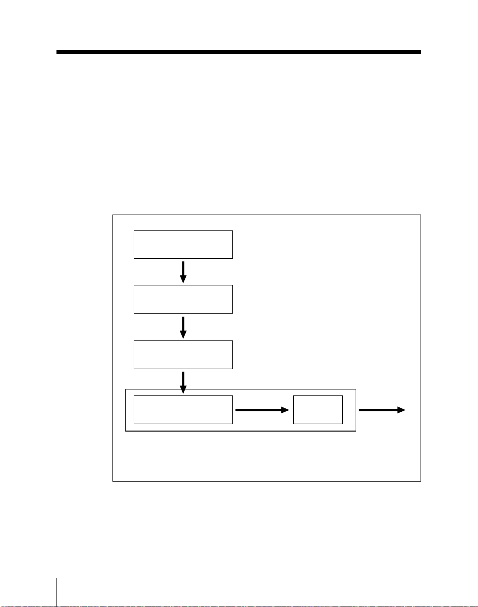
Before Beginning Image Creation
Examples of signal flow
The following examples show how the outputs of the M/E banks can be fed
to each other, in the two principal system types.
For convenience it is assumed here that the signals are fed in the fixed order
from M/E-1 to M/E-2 to M/E-3, but in fact any of these banks can feed any
of the others. In a 3.5-M/E system, however, it is not possible to feed the
output of the PGM/PST bank to one of the M/E banks.
Example signal flow in a 3.5-M/E system
The following diagram shows an example of the signal flow in a 3.5-M/E
system.
M/E-1 bank
M/E-1 output
video
M/E-2 bank
M/E-2 output
video
4-4
M/E-3 bank
M/E-3 output
video
PGM/PST bank
a) The downstream keyer is also controlled from the PGM/PST section of the
control panel.
Chapter 4 Basic Operations for Image Creation
Program video
Downstream
a)
keyer
System
program output
Page 89
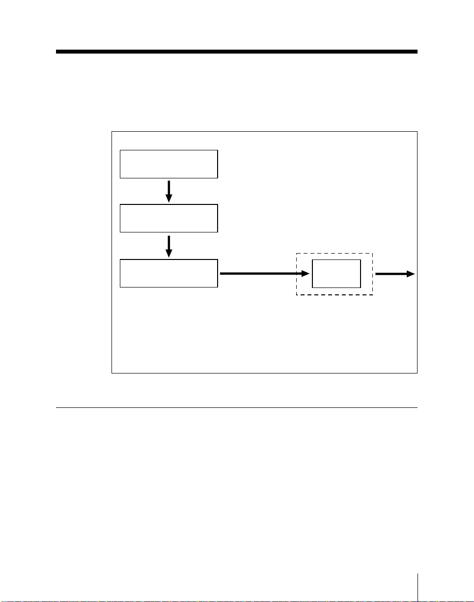
Example signal flow in a 3-M/E system
The following diagram shows an example of the signal flow in a 3-M/E
system, with the output from the M/E-3 bank set up to be the switcher
program output.
M/E-1 bank
M/E-1 output
video
M/E-2 bank
M/E-2 output
video
M/E-3 bank
a) When no downstream keyer is installed, the M/E-3 output becomes the
system program output.
b) The downstream keyer is controlled from the downstream keyer control unit
installed in the control panel (the BKDS-7032 option).
Signal Selection
Pressing a cross-point button selects a signal on the corresponding bus, but in
some cases a single row of cross-point buttons is used for more than one bus.
In this case it is first necessary to delegate the row of cross-point buttons to
the required bus. The next section describes which rows of cross-point
buttons belong to which buses.
For details of the assignment of signals to cross-point button columns, see
the next page.
M/E-3 output video
(switcher program
a)
output)
Downstream
b)
keyer
System
program
output
Chapter 4 Basic Operations for Image Creation
4-5
Page 90

Before Beginning Image Creation
Cross-point buttons and buses
The relation between cross-point buttons and buses depends on the model of
control panel, as shown in the following tables.
Cross-point buttons and buses for the BKDS-7012/7021/7022
Bus
Background A
Background B
Key 1 fill
Key 2 fill
Key 1 source Press the KEY 1 or
Key 2 source K2 M/E-1, M/E-2, M/E-3
Program (BKDS7021/7022)
Preset (BKDS-7021/
7022)
AUX 1 to AUX 13 Press the required
Edit preview
Frame memories 1
and 2
M/E utility bus
Downstream keyers 1
to 4, key fill (when
DMK-7000
connected)
Downstream keyers 1
to 4, key source
(when DMK-7000
connected)
AUX 14 to AUX 28
Button row Banks
A M/E-1, M/E-2, M/E-3
B
K1
K2
K1 M/E-1, M/E-2, M/E-3
Auxiliary bus cross-point buttons
Auxiliary bus cross-point buttons
PST
Auxiliary bus cross-point buttons
Auxiliary bus cross-point buttons Hold down the
Auxiliary bus cross-point buttons In the corresponding
Auxiliary bus cross-point buttons
Delegation operation
None required.
KEY 2 button in the key
control section of the
relevant M/E bank to
delegate the
corresponding keyer,
then hold down the
SPLIT button.
None required.PGM PGM/PST
auxiliary delegation
button, turning it on.
corresponding one of
the DSK1 to DSK4
buttons in the
downstream keyer
control section.
one of the DSK1 to
DSK4 menus, hold
down the SPLIT button.
In the setup menu, set
the auxiliary bus bank
blank button to AUX 14
- 28, then press this
button, turning it on.
Thereafter, press the
required auxiliary
delegation button
turning it on.
4-6
Chapter 4 Basic Operations for Image Creation
Page 91

Cross-point buttons and buses for the BKDS-7011/7023
Bus Button row Banks Delegation operation
Background A
Background B
Key 1 and key 2 fill K M/E-1, M/E-2, M/E-3 Press the KEY 1 or
Key 1 and key 2
source
7023)
Preset (BKDS-7023)
AUX 1 to AUX 13
Edit preview
Frame memories 1
and 2
M/E utility buses
Downstream keyers 1
to 4, key fill (when
DMK-7000
connected)
Downstream keyers 1
to 4, key source
(when DMK-7000
connected)
AUX 14 to AUX 28
A M/E-1, M/E-2, M/E-3 None required.
B
KEY 2 button in the
corresponding key
control section, turning
it on.
K M/E-1, M/E-2, M/E-3 Press the KEY 1 or
Auxiliary bus cross-point buttons
PGM/PST
PST
Auxiliary bus cross-point buttons Press the required
Auxiliary bus cross-point buttons Hold down the
Auxiliary bus cross-point buttons In the corresponding
Auxiliary bus cross-point buttons
KEY 2 button in the key
control section of the
relevant M/E bank to
delegate the
corresponding keyer,
then hold down the
SPLIT button.
None required.PGMProgram (BKDS-
auxiliary delegation
button, turning it on.
corresponding one of
the DSK1 to DSK4
buttons in the
downstream keyer
control section.
one of the DSK1 to
DSK4 menus, hold
down the SPLIT button.
In the setup menu, set
the auxiliary bus bank
blank button to AUX 14
- 28, then press this
button, turning it on.
Thereafter, press the
required auxiliary
delegation button
turning it on.
Chapter 4 Basic Operations for Image Creation
4-7
Page 92

Before Beginning Image Creation
Assigning signals to cross-point button columns
Each row of cross-point buttons in the M/E banks, PGM/PST bank (3.5-M/E
systems only), and auxiliary bus bank includes 29 basic buttons for signal
assignment. It is also possible to assign a shift function to one button,
allowing a maximum total of 56 assignable signals. Using a setup menu
operation, you can assign any of the columns in either the unshifted or shifted
state to any of the signals from the INPUTS 1 to 60 connectors on the I/O
expansion unit (DVS-V6464M or HDS-X3600), or to various signals
generated internally by the switcher.
For the procedure for assignment, see page 14-63.
Although in principle the signal assignment is to a column of buttons, there
are cases in which a particular signal cannot be selected on a particular bus.
For details of the restrictions on selecting certain signals, see page 14-62.
Using the shift function
The 29 cross-point buttons in each row are numbered 0 to 28. Normally the
rightmost button is the shift button; the buttons to which signals are assigned
are then numbered 0 to 27 in the unshifted state, and 30 to 57 in the shifted
state.
4-8
To select the signal corresponding to the unshifted state, press the required
button alone; to select the signal corresponding to the shifted state, hold
down the shift button, then press the required button. Note that for the
auxiliary bus bank there is the dedicated SHIFT button, and even when not
using the 29th button as a shift button, holding down the SHIFT button and
pressing a cross-point button selects one of the second set of signals.
It is also possible, using a setup menu operation, to switch the shift button to
be the leftmost button instead of the rightmost. In this case the assignable
signals are numbered 1 to 28 and 31 to 58. You can also use a setup menu
operation so that the shift button acts as a “shift lock” button.
All shift function settings are carried out in a setup menu (see page 14-66).
Chapter 4 Basic Operations for Image Creation
Page 93

Source name indications
Using a setup menu operation, you can assign an identifier of up to eight
characters to each signal, for display on the control panel.
For details of the procedure for assigning signal names, see page 14-64.
The source name display on the control panel shows the first two and the last
two characters of the specified identifier.
When using the shift function, hold down the SHIFT button beside the source
name displays to show the identifiers assigned to the shifted buttons.
While you hold down the shift button for the cross-point button row, the
second set of names appears here.
If you are using the switcher and a DVS-B series routing switcher connected
by a BKDS-7700, the signal names selected on the routing switcher can be
displayed.
Reentry buttons
To use the output of one M/E bank as a background input to another M/E
bank, press the corresponding button (M/E-1, M/E-2, or M/E-3) at the right
of the bank.
For example, to use the output of the M/E-1 bank as background B on the
M/E-2 bank, press the M/E-1 button in the B row of cross-point buttons in
the M/E-2 bank.
Cross-point button indications
In any row of cross-point buttons, the last button pressed is selected, and
lights. A button which lights red indicates that the signal is being fed to the
corresponding bus, and is forming part of the program output. A button
which lights amber is selected, but the signal is not currently reaching the
program output.
Note
The red and amber color coding thus corresponds to buttons lighting in high
and low tally respectively on some switchers.
Chapter 4 Basic Operations for Image Creation
4-9
Page 94
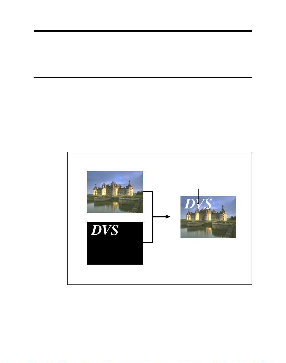
Using the Mix/Effects Banks
This section describes some of the effects which you can create using mix/
effects banks.
Backgrounds and Keys
You can use each of the mix/effects banks to insert one or two keys into a
background video image.
To define a key requires two video signals, the key source, which specifies
which part of the background is cut out, and the key fill, which supplies the
different video to insert in the cutout.
The following illustration shows an example in which the key source and key
fill signals are actually the same (“self-keying”), and which superimposes
some lettering on the background.
Background
Key
4-10
Key source and key fill
Background and key
Chapter 4 Basic Operations for Image Creation
Page 95

Key types
For each of the M/E banks, you can use the following key types. See the
page numbers indicated in parenthesis for more details.
• Luminance key (page 4-39)
• Linear key (page 4-40)
• Clean key (page 4-40)
• Chroma key (page 4-40)
• Pattern key (page 4-40)
Basic Operating Procedure
On any of the M/E banks, the change from the existing (or “old”) video to
new video is termed a transition.
The following is the basic procedure for carrying out a transition on any of
the M/E banks.
1 Select the background video on the background A bus, using the cross-
point buttons.
2 Select whether the transition is a background or key transition with the
next transition selection buttons in the transition control section.
• For a background transition: press the BKGD button, turning it on.
• To insert or remove key 1: press the KEY 1 button, turning it on.
• To insert or remove key 2: press the KEY 2 button, turning it on.
• To invert the priority of the two keys: press the PRIOR button, turning
it on.
You can press two or more buttons simultaneously, turning them on.
For more details, see the section “Selecting the Next Transition” (page
4-14).
(Continued)
Chapter 4 Basic Operations for Image Creation
4-11
Page 96

Using the Mix/Effects Banks
3 Prepare the new video.
• Select a new background on the background B bus, using the crosspoint buttons.
• When inserting a key, select the key signals and make any other
required settings in the key control section.
For more details of key signal selection and other settings, see the
section “Basic Operation for Key Settings Using a Menu” (page 4-46).
For a cut, skip to step 6. For all other transitions, continue with step 4.
4 Select the transition type with the buttons in the transition type selection
section.
• For a dissolve: press one of the MIX, NAM, and SUPER MIX buttons,
turning it on.
• For a wipe or DME wipe: press one of the WIPE, DME 1, and DME 2
buttons, turning it on. For a dual DME wipe, press both of the DME 1
and DME 2 buttons simultaneously, turning them on.
For more details of transition types, see the section “Selecting the
Transition Type” (page 4-17).
4-12
5 Make the necessary settings, depending on the selected transition type.
For details of the settings, see the sections on the pages indicated in the
following table.
Super Mix “Super Mix Settings” (4-20)
Wipe “Basic Operation for Wipe Settings” (4-102)
DME wipe “DME Wipe Settings” (4-131)
Dual DME wipe “DME Wipe Settings” (4-131)
Transition limit “Setting a Transition Limit” (4-19)
6 Use the transition control section to execute the transition.
• For a gradual transition such as a wipe or dissolve: press the AUTO
TRANS button, or use the fader lever.
• For an instantaneous transition: press the CUT button.
For more details, see the section “Executing a Transition” (page 4-31).
Chapter 4 Basic Operations for Image Creation
Page 97

Background and key transitions
Key cut
Suppose that in step 2 of the procedure above you pressed just the KEY 1
button, and then in step 6 pressed the CUT button. This cuts key 1 in or out,
i.e. instantaneously, and amounts to a cut transition on the M/E bank.
On the other hand, using the KEY ON button in the key control section, you
can cut the key in (or out) independently of the transition on the M/E bank.
For details of key cut operations with the KEY ON buttons, see page 4-34.
Key mix
Using the KEY MIX button in the key control section, you can fade a key in
or out independently of the transition on the M/E bank.
For details of the operation of the KEY MIX buttons, see page 4-35.
Checking the status of keys and their priority
The ON and OVER indicators above the KEY 1 and KEY 2 buttons in the
transition control section provide additional status information for the two
keys. The following table shows the significance of the various button and
indicator states. (The key whose priority is indicated as “over” is the key
which appears when the two keys overlap.)
Indicator/button state Key state
Transition
control section
Key control
section
Key 1 or 2 ON indicator lit Corresponding key is included in the
Key 1 or 2 OVER indicator
lit
KEY ON button for key 1 or
2 is lit amber
KEY ON button for key 1 or
2 is lit red
output from the M/E bank.
Corresponding key is over the other
key.
Corresponding key is included in the
output from the M/E bank, but not
program output.
Corresponding key is included in the
program output.
Chapter 4 Basic Operations for Image Creation
4-13
Page 98
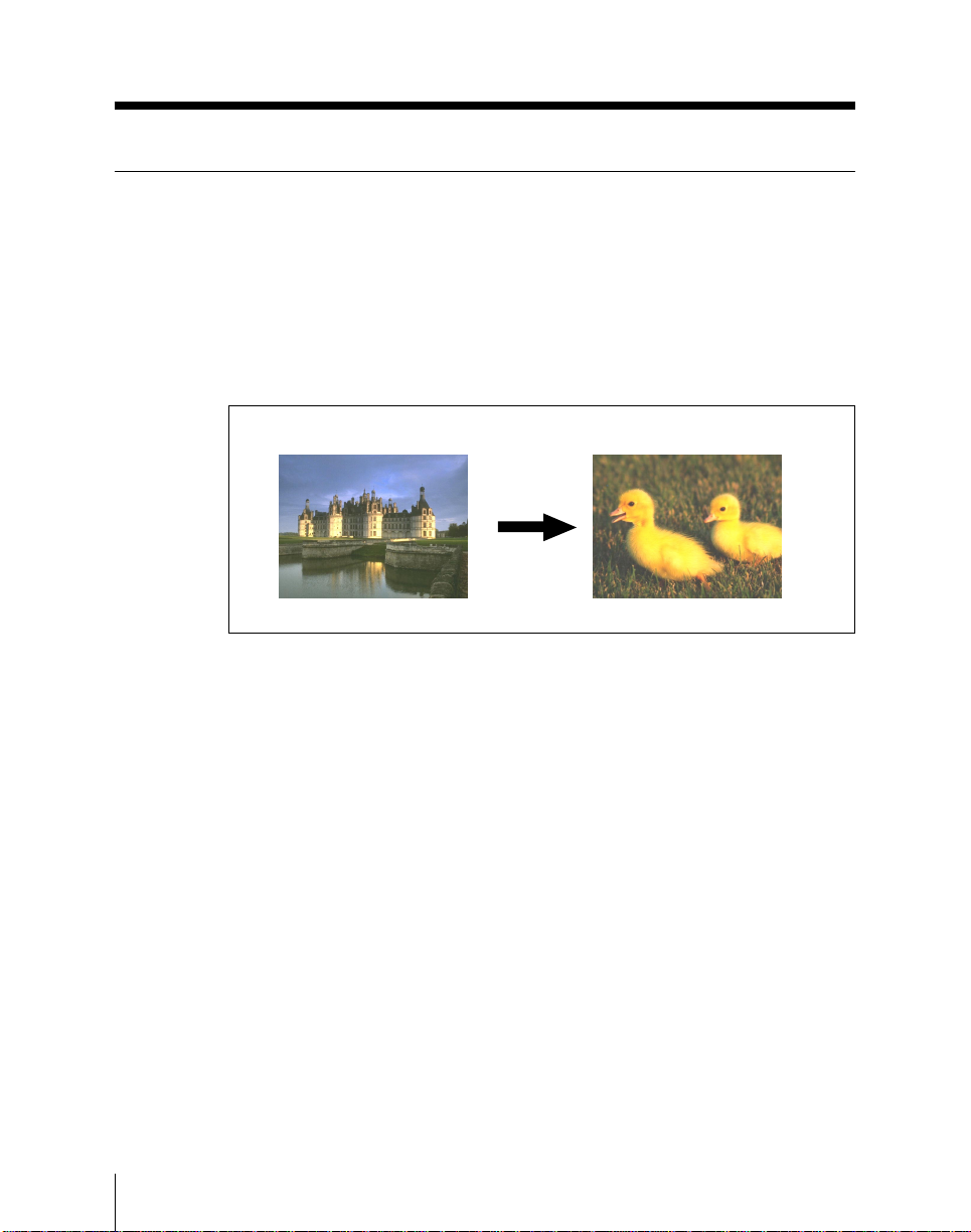
Using the Mix/Effects Banks
Selecting the Next Transition
In a transition you can change between the two backgrounds, or insert or
remove either of the keys, or carry out any of these operations
simultaneously. The following figures illustrate some possible effects.
Background transition
A background transition switches from the currently selected background A
(old video) to background B (new video).
Background A Background B
Background transition
4-14
In bus flip-flop mode, a background transition always proceeds from
background A to background B, and at the end of the transition the signal
selections on the two background buses flip-flop. This means that except
during a transition it is always background A which feeds the output of each
of the mix/effects banks.
For more details, see the section “Bus fixed mode and bus flip-flop mode”
(page 4-37).
Chapter 4 Basic Operations for Image Creation
Page 99
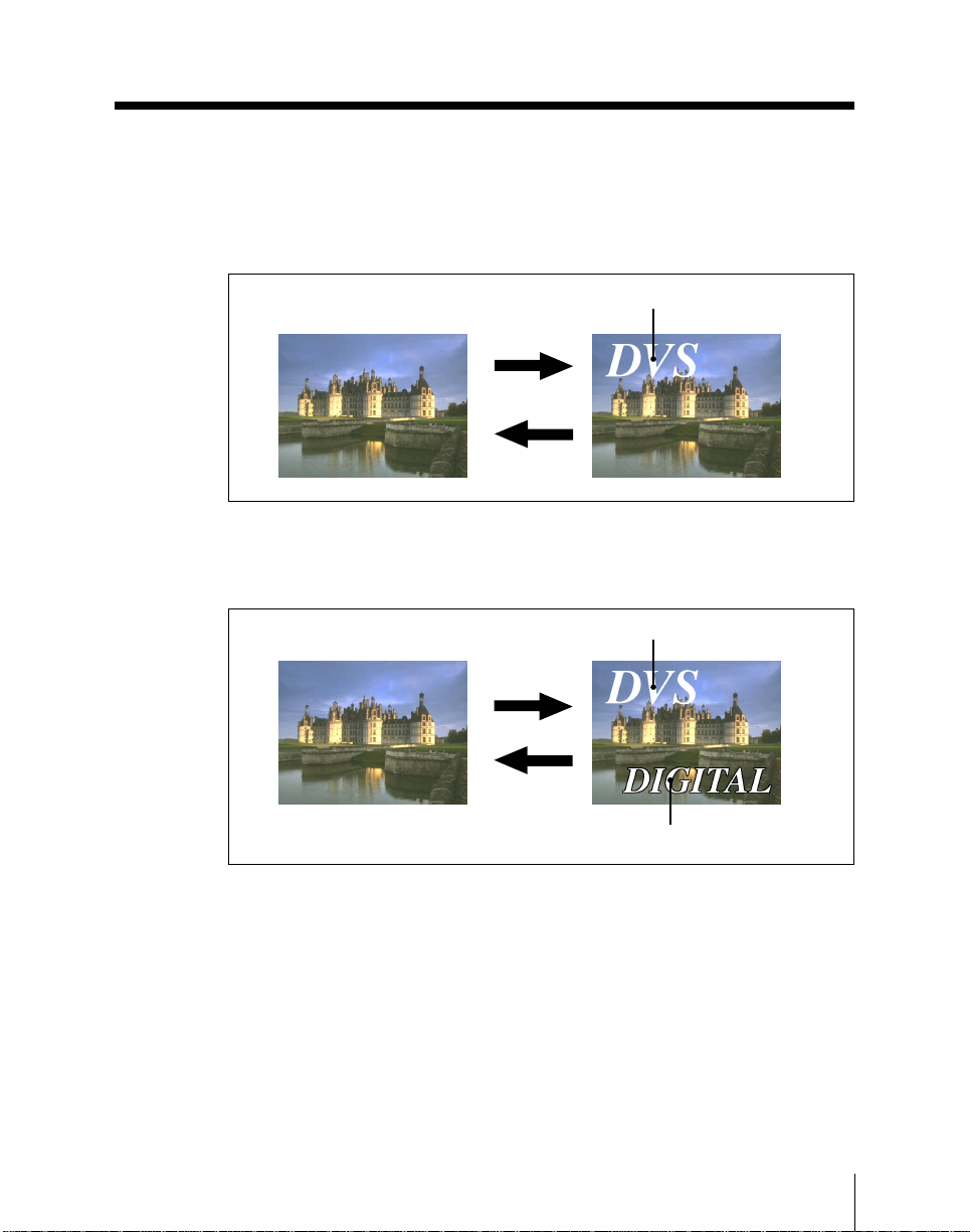
Key transitions
Inserting or removing a single key
This inserts or removes key 1 or key 2 in the current video.
Inserting or removing both keys simultaneously
This inserts or removes both key 1 and key 2 in the current video.
Key 1 or key 2
Inserting key
Removing key
Inserting and removing key 1 or key 2
Key 1
Inserting keys
Removing keys
Key 2
Inserting and removing key 1 and key 2 simultaneously
Chapter 4 Basic Operations for Image Creation
4-15
Page 100
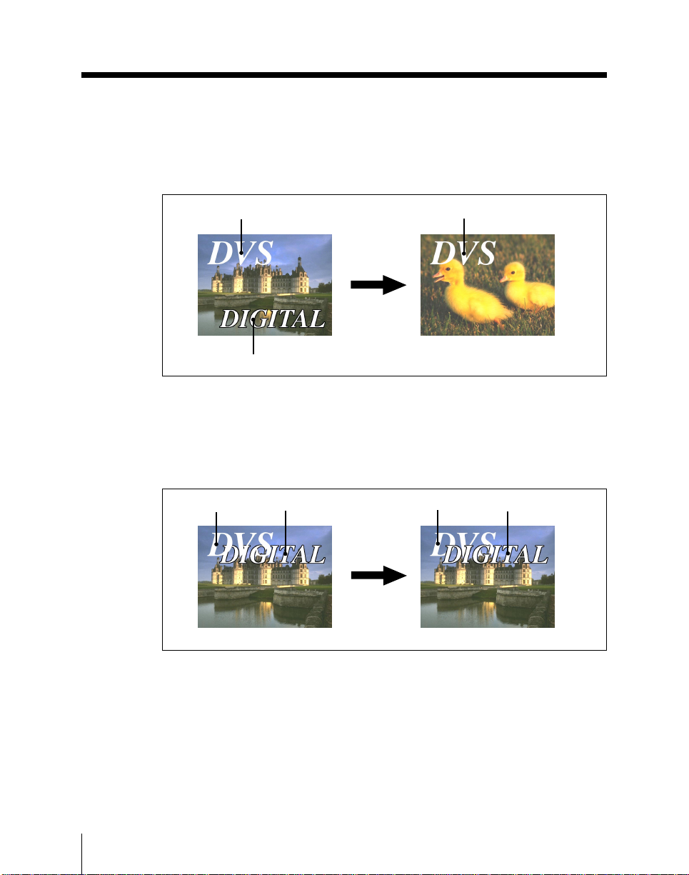
Using the Mix/Effects Banks
Carrying out background and key transitions simultaneously
You can switch any combination of the background and keys 1 and 2
simultaneously. The following example illustrates leaving key 1 unchanged,
while changing both the background and key 2.
Key 1
Key 2
Changing the background and key 2 simultaneously
Inverting the priority of keys 1 and 2
This transition inverts the priority of the two keys. In the following example,
before the transition key 1 is over key 2, and parts of key 2 may be obscured
by key 1. After the transition this relation is reversed.
Key 1 Key 2 Key 1 Key 2
Key 1
4-16
Inverting the priority of keys 1 and 2
Chapter 4 Basic Operations for Image Creation
 Loading...