

Page 1

DVP-S7000
DVD MECHANISM
OPERATION MANUAL
i
III
III lllll IIII
illil lllll lilii
392162751
illli
III1
ill1
llli
SONY@
Page 2

1.
Mainparts
2.
Operation ofparts
layout . . . . . . . . . . . . . . . . . . . . . . . . . . . . . . . . . . . . . . . . . . . . . . . . . . . . . . . . . . . . . . . . . . . . . . . . . . . . . . . . . . . . . . . . . . . . . . . . . . . . . . . . . . .
CONTENTS
3
.........................................................................................................
4
2-l. Operation of spindle base with loading motor..
1)
Tray
open ................................................................................................................ 4
2) Tray IN
2-2.
Operation of optical pick-up block with sled motor
2-3.
Operation of slide base with
3.
Tray close (Disc IN)
3-l. With disc (1)
With disc (2)
3-2.
Without disc..
4.
PB . . . . . . . . . . . . . . .
.................................................................................................................... 7
skew
motor
.....................................................................................................
.............................................................................................................
..............................................................................................................
............................................................. .:. ............................................ 25
*
. . . . . . . . . . . . . . . . . . . . . . . . . . . . . . . . . . .
*
. . . . .
*
. . . . . . . . . . . . . . . . . . . . . . . . . . . . .
.......................................................... 4
.................................................
.................................................................
*
. . . . . . . . . . . . . . . . . . . . . . . . . . . . . . . ..*.............
10
13
17
17
21
29
5. PB-PAUSE . . . . . . . . . . . . . . . . . . . . . . . . . . . . . . . . . . . . . . . . . . . . . . . . . . . . . . . . . . . . . . . . . . . . . . . . . . . . . . . . . . . . . . . . . . . . . . . . . . . . . . . . . . . . . . . .
6.
PB-STOP . . . . . . . . . . . . . . . . . . . . . . . . . . . . . . . . . . . . . . . . . . . . . . . . . . . . . . . . . . . . . . . . . . . . . . . . . . . . . . . . . . . . . . . . . . . . . . . . . . . . . . . . . . . . . . . . . . .
7.
Tray open (Disc OUT)
. . . . . . . . . . . . . . . . . . . . . . . . . . . . . . . . . . . . . . . . . . . . . . . . . . . . . . . . . . . . . . . . . . . . . . . . . . . . . . . . . . . . . . . . . . . . . . . .
-2-
33
34
36
Page 3
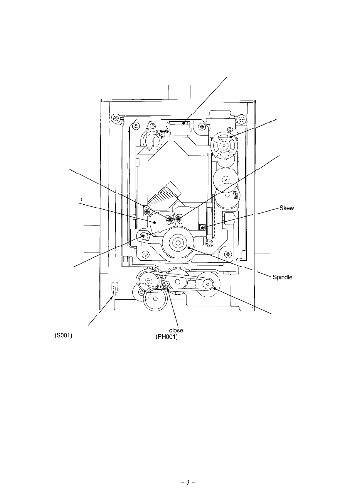
1. Main parts layout
!
\ I
I
CD optical
pick-up
.
Optical pick-up
block
Skew motor
/
/Skew
Sled motor
DVD optical
pick-up
sensor
CD sensor
/
Tray open sensor switch
(SOOl)
r
1
’
Splndle motor
\
Loading motor
Tray
close
sensor
(PHOOl)
Fig. l-l
-3-
Page 4
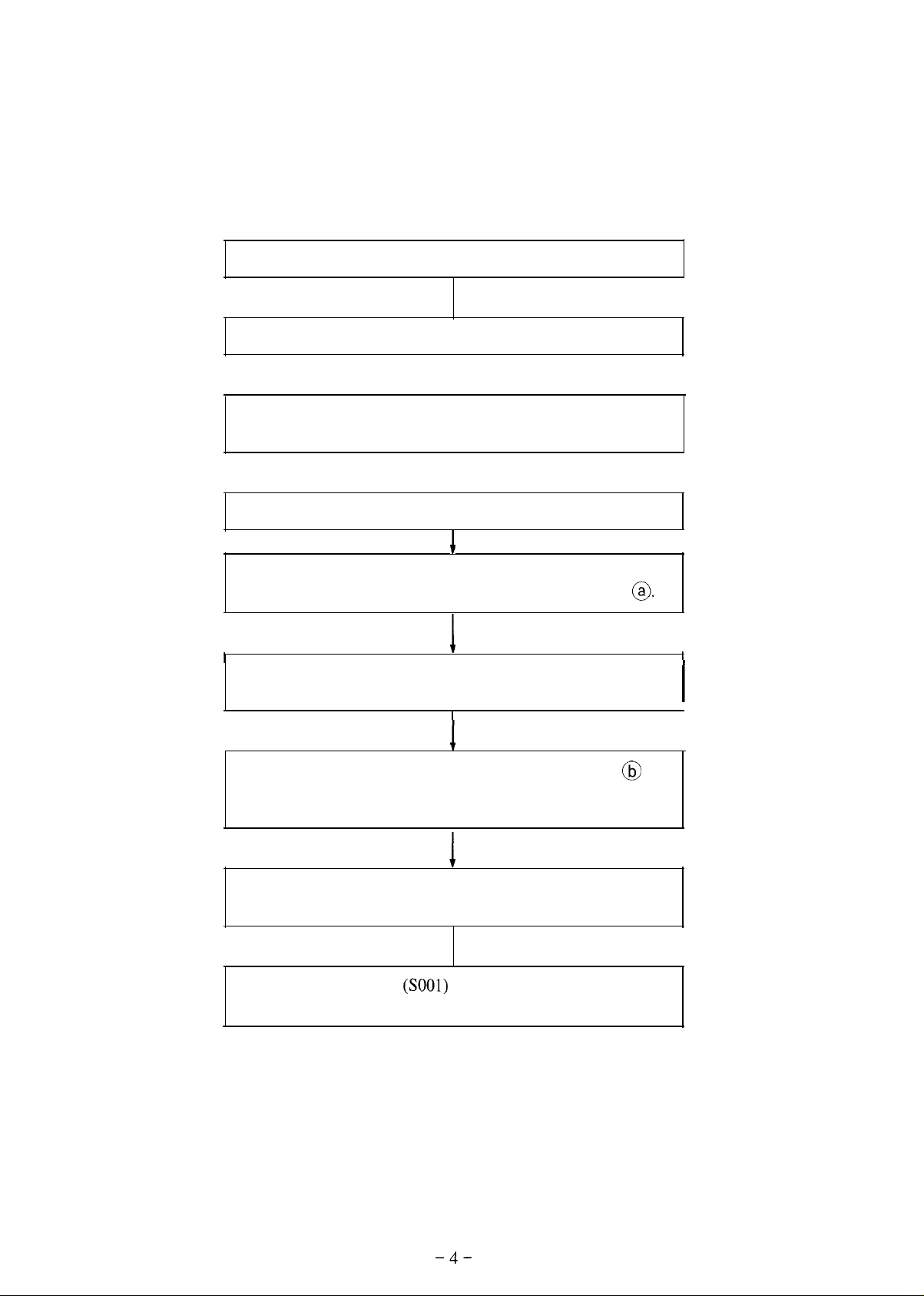
2. Operation of parts
2-l. Operation of spindle base with loading motor
1) Tray open
Press open/close button.
Loading motor rotates in the direction of arrow mark.
I
Loading (midway) gear rotates in the direction of arrow mark
through belt and loading pulley.
I
Tray driving gear rotates in the direction of arrow mark.
+
Tray driving gear meshed with tray rack unit, and loading
(midway) gear both move in the direction of arrow mark @.
I
Drive gear rotates in the direction of arrow mark to rotate cam
gear in the direction of arrow mark.
1
I
1
Spindle base moves down in the direction of arrow mark
centering around the fulcrum@, and the gap between press
pulley and spindle motor becomes large.
* Disc is released from chucking.
Tray driving gear further rotates and tray is pushed out in
the direction of arrow mark.
* Disc can be set.
Tray open sensor switch
motor stops.
(SOOl)
detects “tray open” when loading
I
I
@
-4-
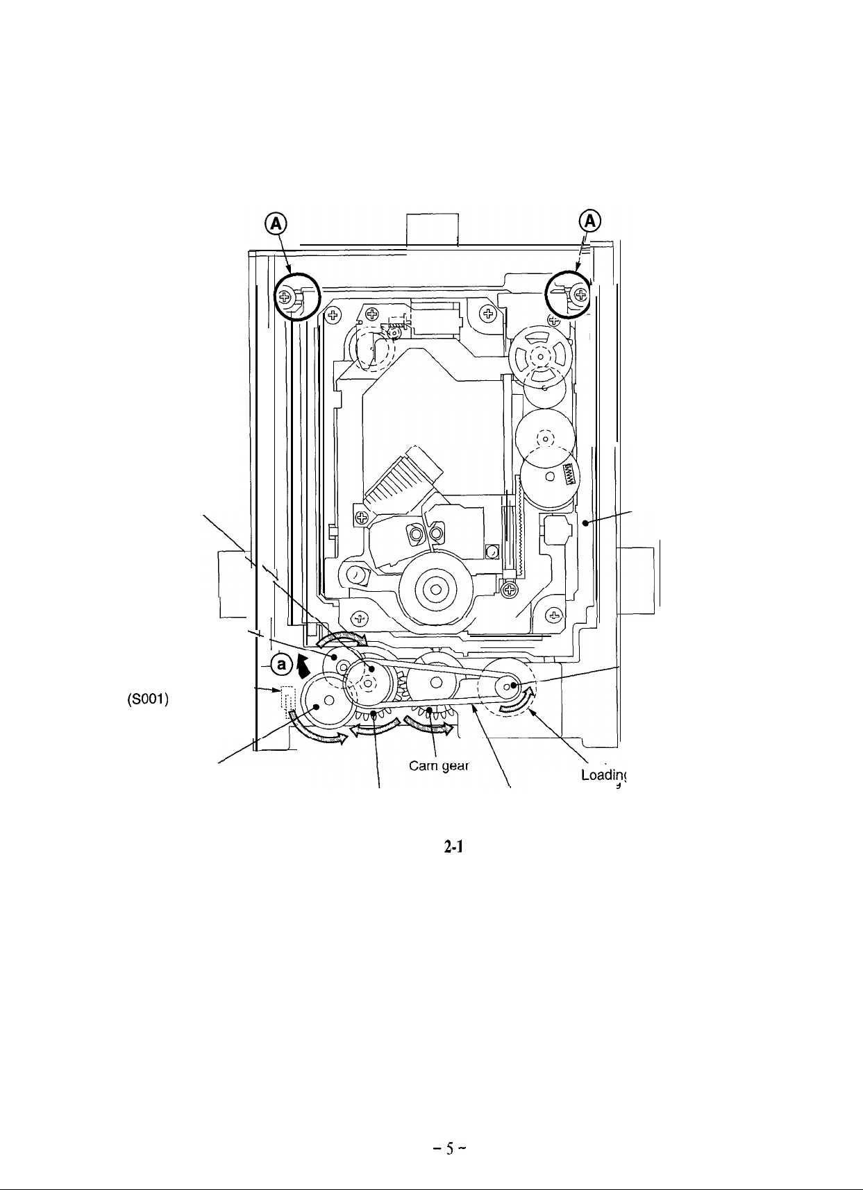
Page 5
I
I
I
I
I
r’l
i
Loading pulley
‘p
Loading
(midway) gear,
Tray open
sensor switch ---
(SOOl)
Tray driving
L
gear
\
.,
-0’
, Spindle base
\,
a
Loabint
Drive’ gear
Fig.
2-1
Belt
, Motor pulley
motor
-5-
Page 6
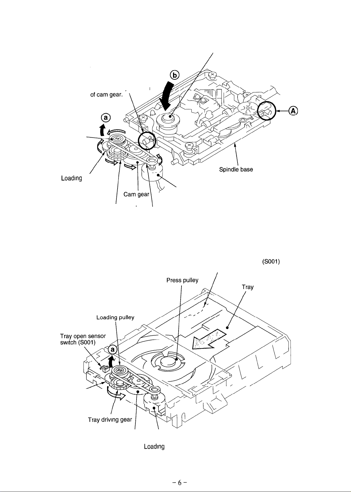
Loading pulley
Loading (midway)
gear
This portion touches
the cam gear, allowing
the spindle base to
move down
by the cam
Spindle motor
Loading motor
Tray driving gear
Belt
Fig. 2-2
Tray open sensor switch
to ON by the projection under the tray.
(SOOl)
IS set
Loading (midway)
gear
.
-l-L
Cam ‘gear
\
Loading motor
Fig. 2-3
-6-
Page 7
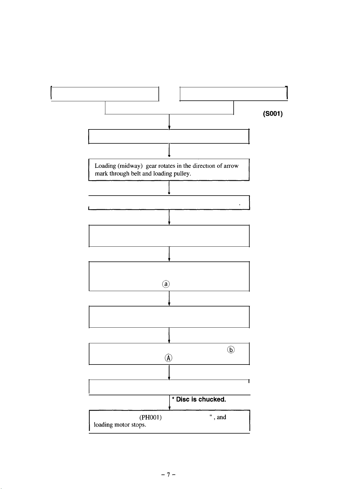
2) Tray IN
I
Press open/close button. Slightly push in the tray with hand.
* Tray open sensor
switch (SOOl) OFF
I
Loading motor rotates in the direction of arrow mark.
I
I
Loading (midway) gear rotates in the direction of arrow
mark through belt and loading pulley
*
I
I
1
I
I
Tray driving gear rotates in the direction of arrow mark.
r
~~~
~~
~~ ~ ~~
Tray meshed with tray dnving gear is pulled in the
direction of arrow mark.
When tray is pulled in and reaches the given position, both
the tray driving gear and loading (midway) gear move in
the direction of arrow mark @ .
I
Drive gear rotates in the direction of arrow mark to rotate
cam gear in the direction of arrow mark.
I
Spindle base moves up in the direction of arrow mark
centering around the fulcrum @ .
I I
Disc is set between press pulley and spindle motor.
I
Tray close sensor (PHOOl) detects “tray close
I
@
I
-7-
Page 8

Loading pulley
‘r\
Tray close
sensor
(PHOOl)
/
Loading
(midway) gear,
Tray driving gear
L-
-
a
O
Drive gear
I
Cam gear
Fig. 2-4
\
Belt
’
\
Loading motor
Spindle base
-8-
Page 9
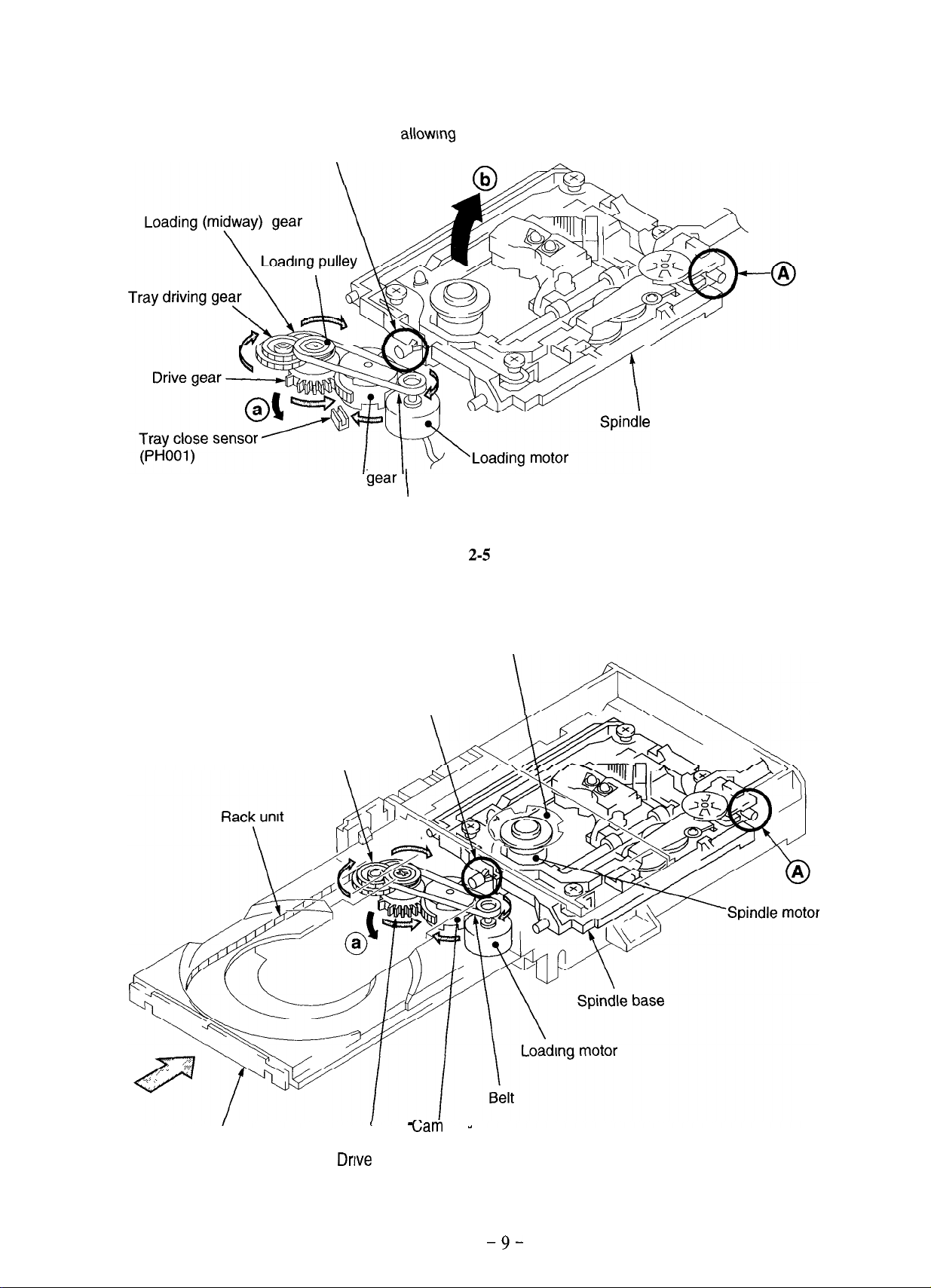
The portion touches cam gear, allow\ng spindle
base to move up by the cam of cam gear.
base
Cam bear
This portion touches
cam gear.
Tray driving gear
\
I
Belt
Fig.
2-5
Press pulley
\
Tray
I
Drive gear
Gam
gear
Fig. 2-6
-9-
Page 10
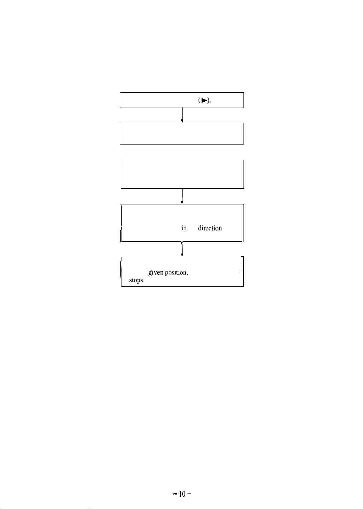
2-2. Operation of optical pick-up block with sled motor
Press PB button
Sled motor rotates in the direction of gray
arrow mark.
Limiter gear ass’y rotates in the direction
of gray arrow mark through gear (S-A) and
gear (S-B).
Limiter gear ass’y is meshed with the rack
gear of optical pick-up block and optical
pick-up block moves m the
1
gray arrow mark.
’
.
I
I
i
(b).
drrectron
of
I
When optical pick-up block is moved and
reaches given posmon, and sled motor
( stops. .
.
.
* Sled motor detects FG.
* The gray arrow mark indicates the movement of optical
pick-up block from inner to outer surface of disc (NEXT).
* The black arrow mark indicates reverse movement (PREV).
- lo-
Page 11
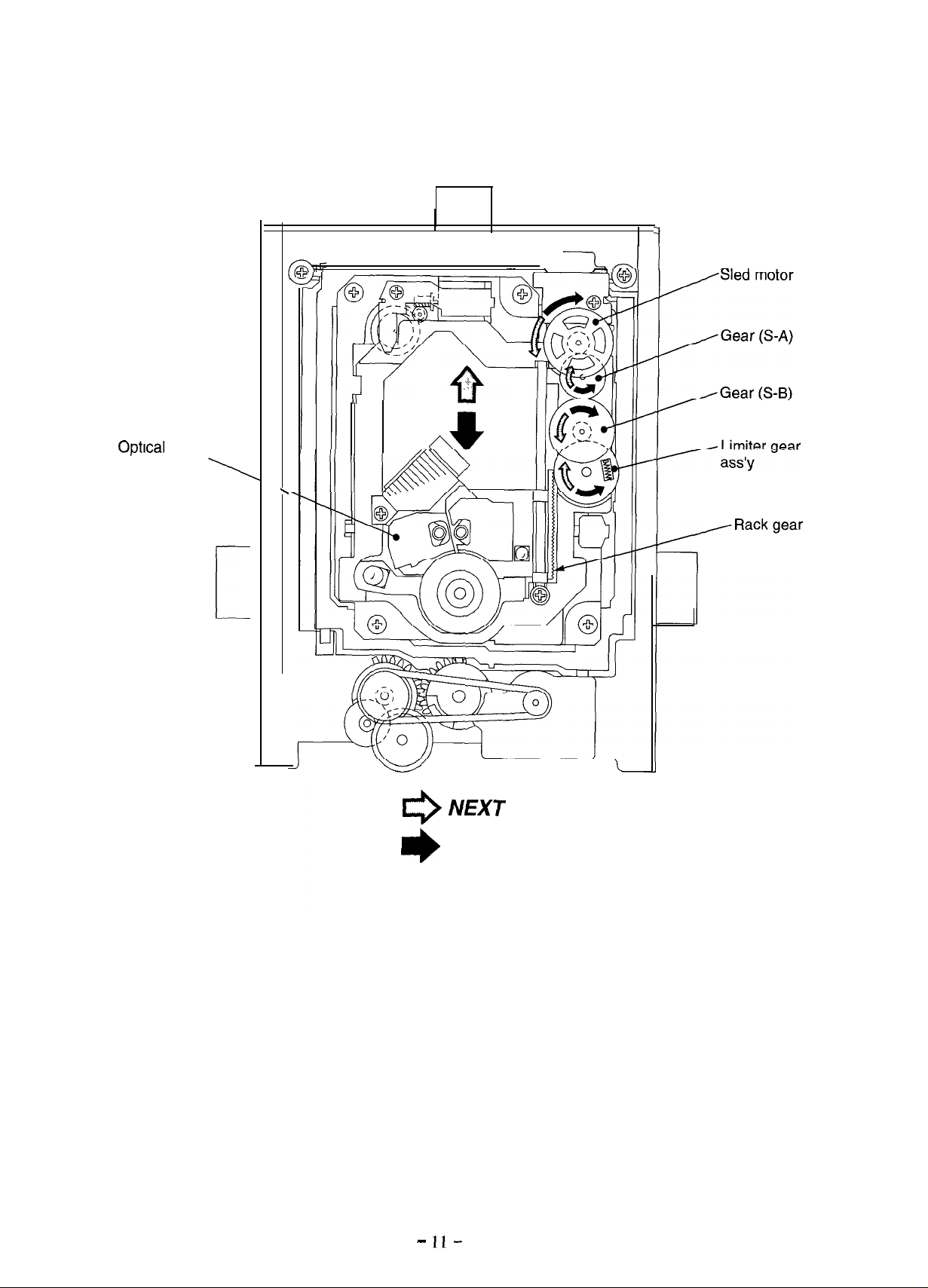
OptIcal
block
1
:
pick-up
.
1
0
*
Fig. 2-7
- ll-
NEXT
PREV
Page 12

C---m,-.
Sled motor
Spindle motor
Optical
Rack gear
pick-up block
\
Limiter gear ass’y
\
Fig. 2-8
Rack gear
I
Sled motor
\
V
I
Spindle motor \
-
\
Limiter gear ass’y
Fig. 2-9
- 12-
Geat
(S-B)
Page 13

2-3. Operation of slide base with skew motor
The purpose of this operation is to ensure that the detecting beam of optical pick-up block always
makes a right angle with disc. When the skew sensor detects the inclination, the skew motor
starts running to eliminate the inclination.
Skew motor rotates in the direction of arrow mark.
Skew gear rotates in the direction of arrow mark to
rotate the skew cam in the direction of arrow mark.
I
When skew cam rotates, the slide base is tilted in
the direction of arrow mark @centering around
the fulcrum
@.
I
Skew sensor detects the inclination, and skew motor
stops.
I
l
The rotating direction of the skew motor varies with
the direction of inclination.
* Skew gear retainer holds slide base so that it
always touches the skew cam.
-
13
-
Page 14

Skew gear retainer
Slide base
Skew cam
\
\ I
Skew gear
I
I
/
I
/
Skew motor
Skew sensor
Fig. 2-10
- 14-
Page 15

Skew gear
Spindle’motor
Skew cam
\
Fig. 2-11
Skew motor
Skew sensor
- 15-
Page 16

1
Memo
1
............................................................................................................................................ .....
............................................................................................................................................ .....
............................................................................................................................................ .....
............................................................................................................................................
............................................................................................................................................
............................................................................................................................................
............................................................................................................................................
............................................................................................................................................
............................................................................................................................................
............................................................................................................................................
............................................................................................................................................ .....
..................................................................................................................................................
..................................................................................................................................................
..................................................................................................................................................
..................................................................................................................................................
.....
.....
.....
.....
.....
.....
.....
..................................................................................................................................................
..................................................................................................................................................
..................................................................................................................................................
..................................................................................................................................................
..................................................................................................................................................
..................................................................................................................................................
..................................................................................................................................................
..................................................................................................................................................
. . . . . . . . . . . . . . . . . . . . . . . . . . . . . . . . . . . . . . . . . . . . . . . . . . . . . . . . . . . . . . . . . . . . . . . . . . . . . . . . . . . . . . . . . . . . . . . . . . . . . . . . . . . . . . . . . . . . . . . . ..........................
. . . . . . . . . . . . . . . . . . . . . . . . . . . . . . . . . . . . . . . . . . . . . . . . . . . . . . . . . . . . . . . . . . . . . . . . . . . . . . . . . . . . . . . . . . . . . . . . . . . . . . . . . . . . . . . . . . . . . . . . ..........................
. . . . . . . . . . . . . . . . . . . . . . . . . . . . . . . . . . . . . . . . . . . . . . . . . . . . . . . . . . . . . . . . . . . . . . . . . . . . . . . . . . . . . . . . . . . . . . . . . . . . . . . . . . . . . . . . . . . . . . . . ..........................
- 16-
Page 17

Page 18

Sled
rriotor
Gear (S-A)
Optical pick-up
block
\
Spindle motor
\
Loading pulley
T
Loading (midway)
gear
Tray driving gear
-
Drive
/
gear
Gear (S-B)
A
Limiter gear
ass’y
-
DVD optical
pick-up
Spindls
base
3
Tray ck
y
sensor
bse
(PHOOl)
-
\
Loading motor
Belt
Fig. 3-1
-
19-
Page 19

Press pulley
I
DVD optical
pick-up
/
Tray close sensor
(PHOOl)
I
Spindle motor
Cam.gear
Fig. 3-2
DVD optical pick-up
‘\
Rack gear
Ge$
(S-B)
\
Limiter gear ass’y
Fig. 3-3
-
20
-
Page 20

Page 21

Sled motor
Gear (S-A)
Optical pick-up
block
\
Spindle motor
\
Loading
Loading (midway)
gear
Tray driving gear
puyey
Drive
Gear (S-B)
, Limiter gear
ass’y
-
,
y
-
g&ar
DVD
optical
pick-up
Spindle base
Tray close
sensor
(PHOOl)
Fig. 3-4
-
23
-
Page 22

Press pulley
I
DVD optical pick-up
Tray
Tray close sensor
/
(PHOOl)
Cam’gear
Fig. 3-5
-
24
-
Page 23

Page 24

Optical pick-up
block
A
?
-
T
I
-
-
Spindle motor
Loading pulley
Loading
gear
Tray driving gear
(mldway)
l--f
/
Drive gear
\
\
.
\
c
Belt
-
3
, Tray close
DVD optical
pick-up
Splndle base
sensor
(PHOOl)
motor
Fig. 3-6
-
27
-
Page 25

Press pulley
DVD optical pick-up
I
Tray
/
Tray close sensor
(PHOOl)
Cam gear
Fig. 3-7
-
28
-
Page 26

Page 27

Skew cam
Skew gear
Slide
base
DVD optical
pick-up
CD optical
pick-up
OptIcal
pick-up
block
@.\
I
\
(
\
I
/
/
Skew motor
I-
\
\
-
,I ^
e
*
Fig. 4-1
NEXT
PREV
-3l-
Page 28

CD optical pick-up
DVD optical
pick-up
Rack gear
Fig. 4-2
Slide
base
Spindle’motor
Skew cam
Fig. 4-3
Skew gear
A
b
I Skew motor
Skew sensor
-
32
-
Page 29

5, PB -
The unit is set in PAUSE mode by performing the following operation during PB mode.
Spindle motor continues to rotate. Sled motor stops.
PAUSE
Press PAUSE button ( II).
I
I
Gear (S-A), gear (S-B) and limiter
gear
ass’y
stop rotating.
Optical pick-up block stops moving.
Optical pick-up
block
Sled motor
Fig. 5-l
-
33
\i\
Spindle motor
-
Page 30

6. PB - STOP
Press STOP button (H
I
).
I
1 1
Spindle motor stops. Sled motor rotates in the direction of arrow mark.
Gear (S-A) and gear (S-B) rotate in the
;I
Limiter gear
:
ass’y
rotates in the direction of arrow
* When STOP button (m) is
pressed, the optical pick-up
block moves and reaches the
inner surface of disc.
‘I
Sled motor stops.
Optical pie:-up block
I
Spindle motor
Rack gear
I
\
Limiter gear
Fig. 6-1
-
34
-
Sled motor
Gea\r (S-B)
a&y
Page 31

I
I
Sled motor
/
Optical pick-up
block
Gear (S-A)
/
Gear (S-B)
Limiter gear
k
ass’y
, Spindle motor
Fig. 6-2
-
35
-
Page 32

7. Tray open (Disc OUT)
Press open/close button.
Loading motor rotates in the direction of
arrow mark.
i
Loading (midway) gear rotates in the
direction of arrow mark through belt and
loading pulley.
I
Tray driving gear rotates in the direction
of arrow mark.
i
Tray driving gear meshed with rack unit of
tray and loading (midway) gear both move in
the direction of arrow mark
Drive gear rotates in the direction of arrow
mark to rotate cam gear in the direction of
arrow mark.
Spindle base moves down in the direction of
arrow mark @centering around the fulcrum
@
, and the space between press pulley and
spindle motor becomes large.
@.
I
c
Sled motor rotates in the direction of arrow
I
I
1
Limiter gear ass’y rotates in the direction of
arrow mark through gear (S-A) and gear
IBi.
Optical pick-up block moves in the
(
direction
1
o~~f:I.,,.
,
I
I
(S-
)
I
Tray driving gear further rotates, and the tray
is pushed out in the direction of arrow mark.
t
Tray open sensor switch
“tray open” and loading motor stops.
* Disc can be ejected.
(SOOl)
detects
-
36
-
Page 33

\
1
\
A
0
I
/I I
Sled motor
Optical pick-up
block
Cam gear
\
Drive gear
4
Tray open
sensor switch
(SO01 )
Gear (S-A)
Gear (S-B)
, Limiter gear
ass’ y
/Spindle base
, Motor pulley
-
/
Tray driving gear
Fig.
-
37
Loading motor
7-1
-
Page 34

Tray open sensor
to ON by the projection under the tray.
/
switch (SOOl)
is set
Loading motorLoading motor
Fig. 7-2
Tray open sensor
switch
(SOOl)
Press pulley
Tray
Fig. 7-3
-
38
-
Page 35

DVP-S700
Q-921
-627-51
 Loading...