

DVP-NC650V
General
Power requirements 12 0 V AC, 60 Hz
Power consumption 17 W
Dimensions (approx.) 430
× 108 × 414 mm (17 × 4 3/8 × 16 3/8 i n.) (width/height/depth)
including projecting parts
Mass (approx.) 5.5 kg (1 2 lb. 2 oz.)
Operating temperat ure 5°C to 35°C (41°F to 95°F)
Operating humidity 25% to 80%
Supplied accessories
Specifications and design are subjec t to change without notice.
E
NERGY STAR is a U.S. regist ered mark. As an ENERGY STAR Partner, Sony Corporation has determine d
that this product meets the
E
NERGY STAR guidelines for energy efficiency.
Check that you have the following items:
• Audio/video cord (pinplug x 3 y pinplug x 3) (1)
• Remote commander (remote) RMT-D133A (1)
• Size AA (R6) batteries (2)
• S VIDEO cord (1)
RMT-D133A
SERVICE MANUAL
SPECIFICATIONS
System
Laser Semiconductor laser
Signal format system NTSC
Audio characteristics
Frequency response DVD (PCM 96 kHz): 2 Hz to 44 kHz (-2 dB ± 2.0 dB at 44 kHz)
Signal-to-noise ratio (S/N ratio) 115 dB (DVD VIDEO) (LINE OUT L/R (AUDIO) 1/2 jacks only)
Harmonic distortion 0.003 %
Dynamic range DVD VIDEO/SACD: 103 dB
Wow and flutter Less than detected value (±0.001% W PEAK )
SACD: 2 Hz to 100 kHz (-3 dB ± 2.0 dB at 50 kH z)
CD: 2 Hz to 20 kHz (±0.5 dB)
CD: 99 dB
US Model
Canadian Model
Outputs
Jack name Jack type Output level Load impedance
DIGITAL OUT
(OPTICAL)
DIGITAL OUT
(COAXIAL)
LINE OUT L/R
(AUDIO) 1/2
5.1CH OUTPUT Phono j ack 2 Vrms (at 50 kilohms) Over 10 kilohms
LINE OUT (VIDEO) 1/2 Phono jack 1.0 V p-p 75 ohms, sync negative
S VIDEO OUT 1/2 4-pin mini DIN Y: 1.0 Vp-p
COMPONENT VIDEO
B
, PR)
OUT (Y, P
AUDIO IN L/R Phono jack - 47 kilohms
MEGA CONTROL Mini jack - -
PHONES Phone jack 12 mW 32 ohms
Optical output jack -18 dBm Wave length 660 nm
Phono jack 0.5 Vp-p 75 ohms termina ted
Phono jack 2 Vrms (at 50 kiloh ms) Over 10 kilohms
Phono jack Y: 1.0 Vp-p
C: 0.286 Vp-p
PB, PR: 0.7 Vp-p
75 ohms, sync negative
75 ohms terminated
75 ohms, sync negative
75 ohms
SACD/DVD PLAYER

SAFETY CHECK-OUT
After correcting the original service problem, perform the following
safety checks before releasing the set to the customer:
1. Check the area of your repair for unsoldered or poorly-soldered connections. Check the entire board surface for solder
splashes and bridges.
2. Check the interboard wiring to ensure that no wires are
“pinched” or contact high-wattage resistors.
3. Look for unauthorized replacement parts, particularly transistors, that were installed during a previous repair. Point them
out to the customer and recommend their replacement.
4. Look for parts which, though functioning, show obvious signs
of deterioration. Point them out to the customer and recommend their replacement.
5. Check the line cord for cracks and abrasion. Recommend the
replacement of any such line cord to the customer.
6. Check the B+ voltage to see it is at the values specified.
7. Check the antenna terminals, metal trim, “metallized” knobs,
screws, and all other exposed metal parts for AC leakage.
Check leakage as described below.
To Exposed Metal
Parts on Set
LEAKAGE TEST
The AC leakage from any exposed metal part to earth ground
and from all exposed metal parts to any exposed metal part having
a return to chassis, must not exceed 0.5 mA (500 microamperes).
Leakage current can be measured by any one of three methods.
1. A commercial leakage tester, such as the Simpson 229 or RCA
WT -540A. Follow the manuf acturers' instructions to use these
instruments.
2. A battery-operated A C milliammeter. The Data Precision 245
digital multimeter is suitable for this job.
3. Measuring the voltage drop across a resistor by means of a
VOM or battery-operated AC voltmeter. The “limit” indica-
tion is 0.75V, so analog meters must have an accurate low-
voltage scale. The Simpson 250 and Sanwa SH-63T rd are ex-
amples of a passive VOM that is suitable. Nearly all battery
operated digital multimeters that have a 2V A C range are suit-
able. (See Fig. A)
1.5 k
0.15 µF
Fig. A. Using an AC voltmeter to check AC leakage.
Ω
Earth Ground
AC
voltmeter
(0.75 V)
WARNING!!
WHEN SERVICING, DO NO T APPR O A CH THE LASER
EXIT WITH THE EYE TOO CLOSELY. IN CASE IT IS
NECESSARY TO CONFIRM LASER BEAM EMISSION,
BE SURE TO OBSERVE FROM A DISTANCE OF
MORE THAN 25 cm FROM THE SURFACE OF THE
OBJECTIVE LENS ON THE OPTICAL PICK-UP BLOCK.
SAFETY-RELATED COMPONENT WARNING!!
COMPONENTS IDENTIFIED BY MARK 0 OR DOTTED
LINE WITH MARK 0 ON THE SCHEMATIC DIA GRAMS
AND IN THE PARTS LIST ARE CRITICAL TO SAFE
OPERATION. REPLACE THESE COMPONENTS WITH
SONY PARTS WHOSE PART NUMBERS APPEAR AS
SHOWN IN THIS MANUAL OR IN SUPPLEMENTS PUBLISHED BY SONY.
CAUTION:
The use of optical instrument with this product will increase eye
hazard.
CAUTION
Use of controls or adjustments or performance of procedures
other than those specified herein may result in hazardous radiation exposure.
ATTENTION AU COMPOSANT AYANT RAPPORT
À LA SÉCURITÉ!
LES COMPOSANTS IDENTIFIÉS P AR UNE MARQUE 0
SUR LES DIAGRAMMES SCHÉMATIQUES ET LA LISTE
DES PIÈCES SONT CRITIQUES POUR LA SÉCURITÉ
DE FONCTIONNEMENT. NE REMPLACER CES COMPOSANTS QUE PAR DES PIÈCES SONY DONT LES
NUMÉROS SONT DONNÉS DANS CE MANUEL OU
DANS LES SUPPLÉMENTS PUBLIÉS PAR SONY.
– 2 –

TABLE OF CONTENTS
Section Title Page Section Title Page
Service Note ............................................................................ 4
1. GENERAL
Index to Parts and Controls .......................................... 1-1
Getting Started .............................................................. 1-3
Hookups ........................................................................ 1-4
Playing Discs ................................................................. 1-7
Searching for a Scene................................................... 1-11
Viewing Information About the Disc.............................. 1-12
Sound Adjustments ....................................................... 1-13
Enjoying Movies ............................................................ 1-15
Using Various Additional Functions .............................. 1-16
Settings and Adjustments ............................................. 1-18
Additional Information ................................................... 1-21
2. DISASSEMBLY
2-1. Upper Case Removal .................................................... 2-1
2-2. Reinforcement (C) Block Removal................................ 2-1
2-3. Front Panel Section Removal........................................ 2-1
2-4. Rear Panel Block Removal ........................................... 2-1
2-5. AV-60 Board Removal ................................................... 2-2
2-6. MB-101 Board Removal ................................................ 2-2
2-7. Table Ass’y Removal ..................................................... 2-2
2-8. CN-143 Board Removal ................................................ 2-2
2-9. BU Holder Ass’y Removal............................................. 2-3
2-10. Optical Pick-up Removal............................................... 2-3
2-11. Chassis Ass’y Removal................................................. 2-3
2-12. Loading Motor Ass’y (M851) Removal.......................... 2-3
2-13. Power Block Removal ................................................... 2-4
2-14. Internal Views ................................................................ 2-5
2-15. Circuit Boards Location................................................. 2-6
3. BLOCK DIAGRAMS
3-1. Overall Block Diagram................................................... 3-1
3-2. RF/Servo Block Diagram ............................................... 3-3
3-3. Signal Process Block Diagram...................................... 3-5
3-4. Video Block Diagram..................................................... 3-7
3-5. System Control Block Diagram ..................................... 3-9
3-6. Audio (1) Block Diagram ............................................... 3-11
3-7. Audio (2) Block Diagram ............................................... 3-13
3-8. Interface Control Block Diagram ................................... 3-15
3-9. Power (1) Block Diagram .............................................. 3-17
3-10. Power (2) Block Diagram .............................................. 3-19
4. PRINTED WIRING BOARDS AND SCHEMATIC
DIAGRAMS
4-1. Frame Schematic Diagram............................................ 4-3
FRAME (1)..................................................................... 4-3
FRAME (2)..................................................................... 4-5
4-2. Printed Wiring Boards and Schematic Diagrams ......... 4-7
MB-101 Printed Wiring Board ....................................... 4-7
MB-101 (RF AMP, SERVO) Schematic Diagram.......... 4-11
MB-101 (ARP, SERVO DSP) Schematic Diagram........ 4-13
MB-101 (AV DECODER) Schematic Diagram.............. 4-15
MB-101 (BNR) Schematic Diagram .............................. 4-17
MB-101 (DRIVE) Schematic Diagram .......................... 4-19
MB-101 (SYSTEM CONTROL)
Schematic Diagram ....................................................... 4-21
MB-101 (CLOCK GENERATOR)
Schematic Diagram ....................................................... 4-23
MB-101 (FLASH MEMORY, OTP)
Schematic Diagram ....................................................... 4-25
MB-101 (AUDIO DSP) Schematic Diagram.................. 4-27
MB-101 (2ch/6ch DAC) Schematic Diagram ................ 4-29
MB-101 (H3GA) Schematic Diagram............................ 4-31
MB-101 (SACO DECODER) Schematic Diagram ........ 4-33
MB-101 (DSD DSP) Schematic Diagram ..................... 4-35
AV-60 Printed Wiring Board .......................................... 4-37
AV-60 (VIDEO BUFFER) Schematic Diagram .............. 4-39
AV-60 (MUTE) Schematic Diagram ............................. 4-41
AV-60 (AUDIO AMP) Schematic Diagram .................... 4-43
FR-180 (FUNCTION SWITCH) Printed Wiring Board
and Schematic Diagram............................................... 4-45
IF-85 Printed Wiring Board ........................................... 4-47
IF-85 Schematic Diagram ............................................. 4-49
FL-124, SW-356, HP-133 Printed Wiring Boards ........ 4-51
FL-124 (FUNCTION SWITCH),
SW-356 (FUNCTION SWITCH),
HP-133 (HEADPHONE) Schematic Diagrams ............. 4-53
CN-143, LM-64 Printed Wiring Boards ......................... 4-55
CN-143 (CONNECTION), LM-64 (LOADING MOTOR)
Schematic Diagram ....................................................... 4-57
SE-123, TM-125 Printed Wiring Board ......................... 4-59
SE-123 (SENSOR), TM-125 (TURNTABLE MOTOR)
Schematic Diagram ....................................................... 4-61
MPN4801 Printed Wiring Board.................................... 4-63
MPN4801 Schematic Diagram...................................... 4-65
5. IC PIN FUNCTION DESCRIPTION
5-1. System Control Pin Function
(MB-101 Board IC104) .................................................. 5-1
6. TEST MODE
6-1. General Description ...................................................... 6-1
6-2. Starting T est Mode ........................................................ 6-1
6-3. Syscon Diagnosis .......................................................... 6-1
6-4. Drive Auto Adjustment .................................................. 6-5
6-5. Drive Manual Operation ................................................ 6-7
6-6. Mecha Aging ................................................................. 6-10
6-7. Emergency History........................................................ 6-10
6-8. Version Information ....................................................... 6-11
6-9. Video Level Adjustment ................................................ 6-11
6-10. IF CON Self Diagnostic Function.................................. 6-11
6-11. Troubleshooting ............................................................. 6-18
7. ELECTRICAL ADJUSTMENT
7-1. Power Supply Adjustment ............................................. 7-1
1. Power Supply Check (MPN4801 Board)....................... 7-1
2. +11 V Adjustment .......................................................... 7-1
3. +5 V Adjustment ............................................................ 7-1
4. –11 V Adjustment .......................................................... 7-1
7-2. Adjustment of Video System ......................................... 7-2
1. Video Level Adjustment (MB-101 Board) ..................... 7-2
2. Checking S Video Output S-Y....................................... 7-2
3. Checking S Video Output S-C....................................... 7-2
4. Checking Component Video Output Y .......................... 7-2
5. Checking Component Video Output B-Y ...................... 7-3
6. Checking Component Video Output R-Y...................... 7-3
7-3. Adjustment Related Parts Arrangement ....................... 7-4
8. REPAIR PARTS LIST
8-1. Exploded Views ............................................................. 8-1
8-1-1. Main Assembly ......................................................... 8-1
8-1-2. Front Panel Assembly .............................................. 8-3
8-1-3. Table Assembly ........................................................ 8-4
8-1-4. Chassis Assembly.................................................... 8-5
8-2. Electrical Par ts List ....................................................... 8-6
– 3 –
SERVICE NOTE
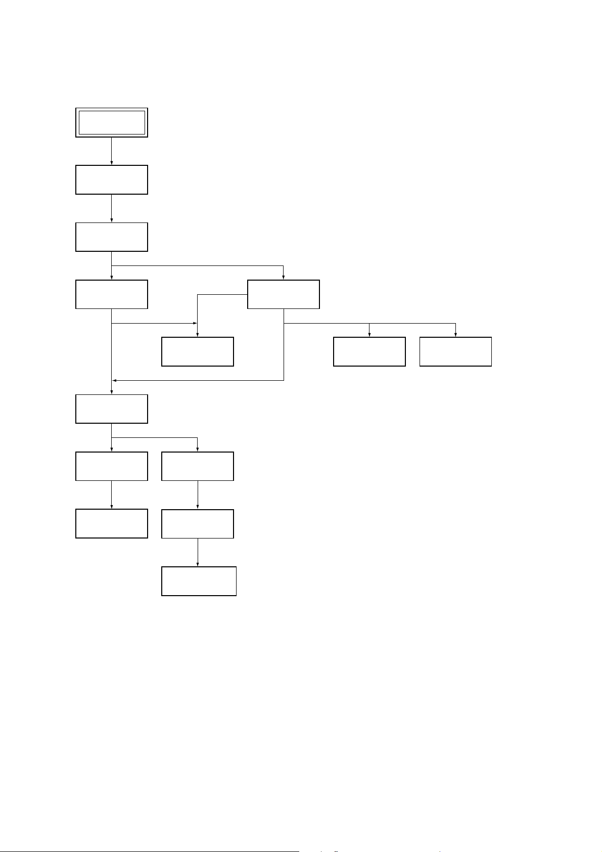
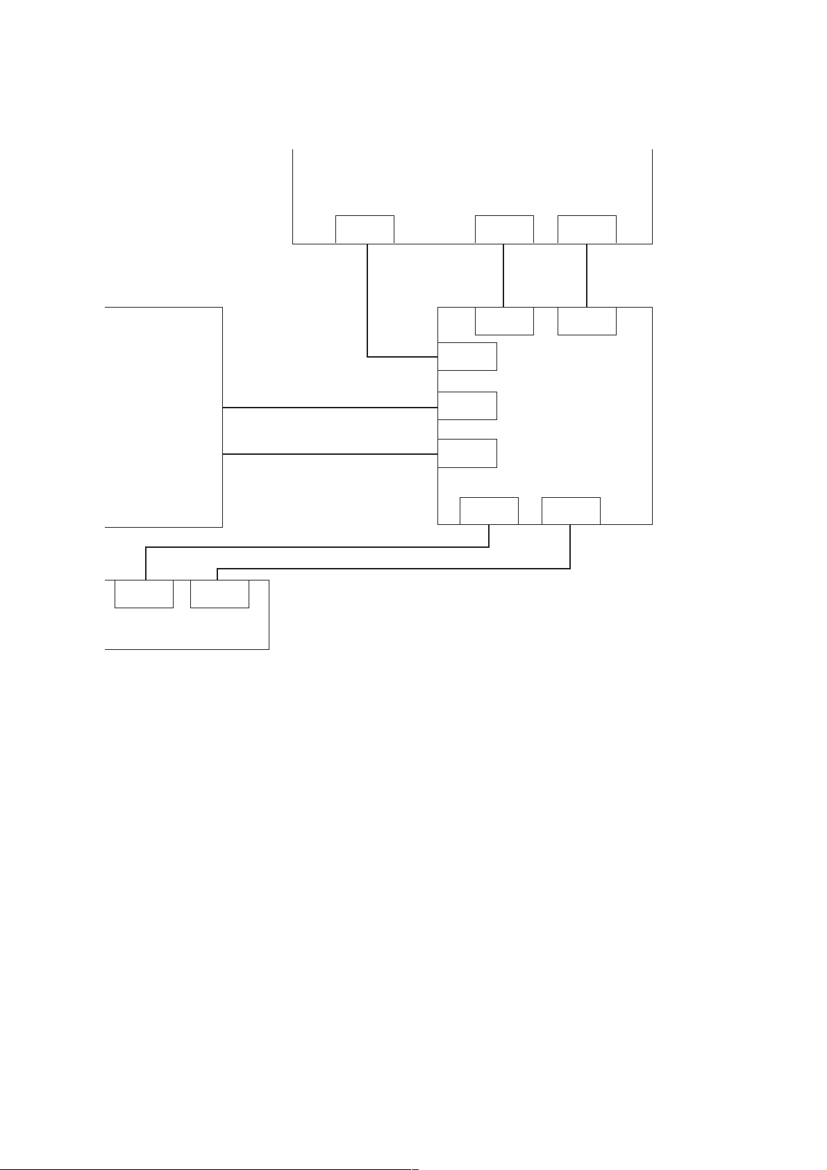
1. DISASSEMBLY
• This set can be disassembled in the order shown below.
Set
Upper case
(Page 2-1)
Reinforcement
(C) block
(Page 2-1)
Front panel section
(Page 2-1)
Table ass’y
(Page 2-2)
BU holder ass’y
(Page 2-3)
Optical pick-up
(Page 2-3)
Pewer block
(Page 2-4)
CN-143 board
(Page 2-2)
Chassis ass’y
(Page 2-3)
Loading motor ass’y
(M851)
(Page 2-3)
Rear panel block
(Page 2-1)
AV-60 board
(Page 2-2)
MB-101 board
(Page 2-2)
– 4 –
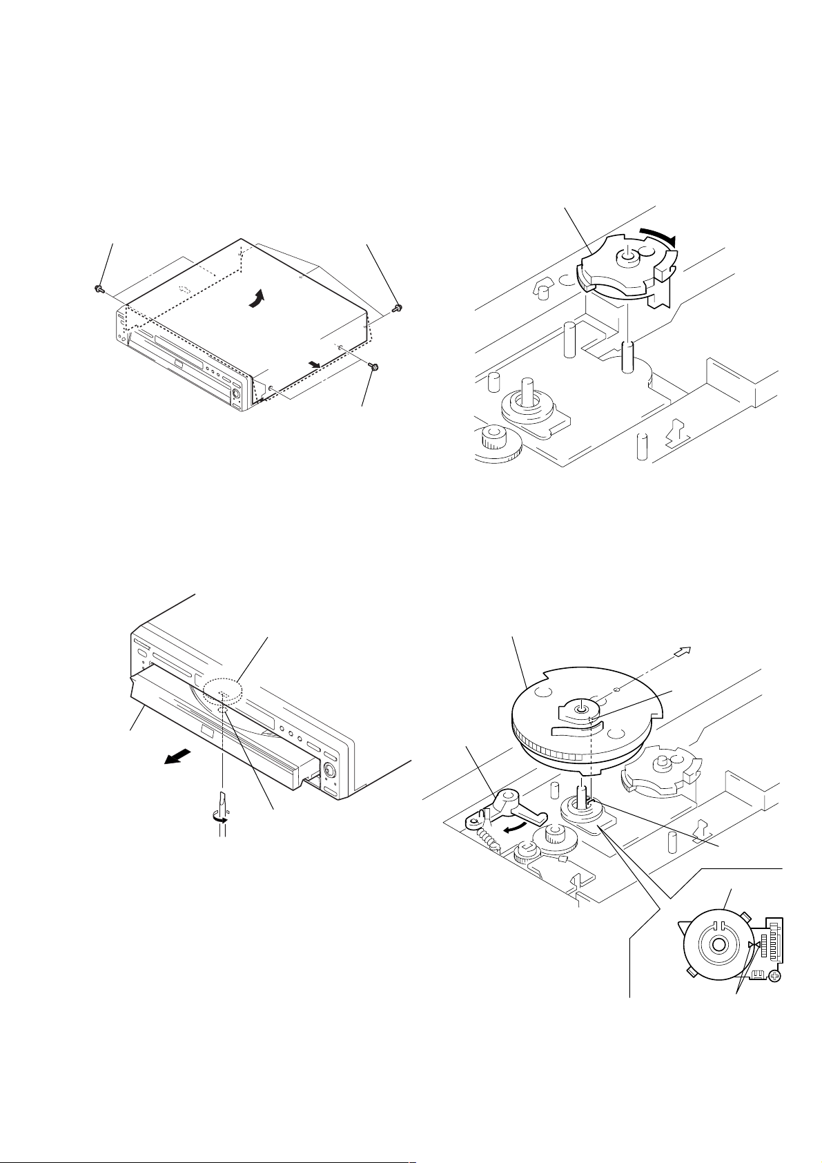
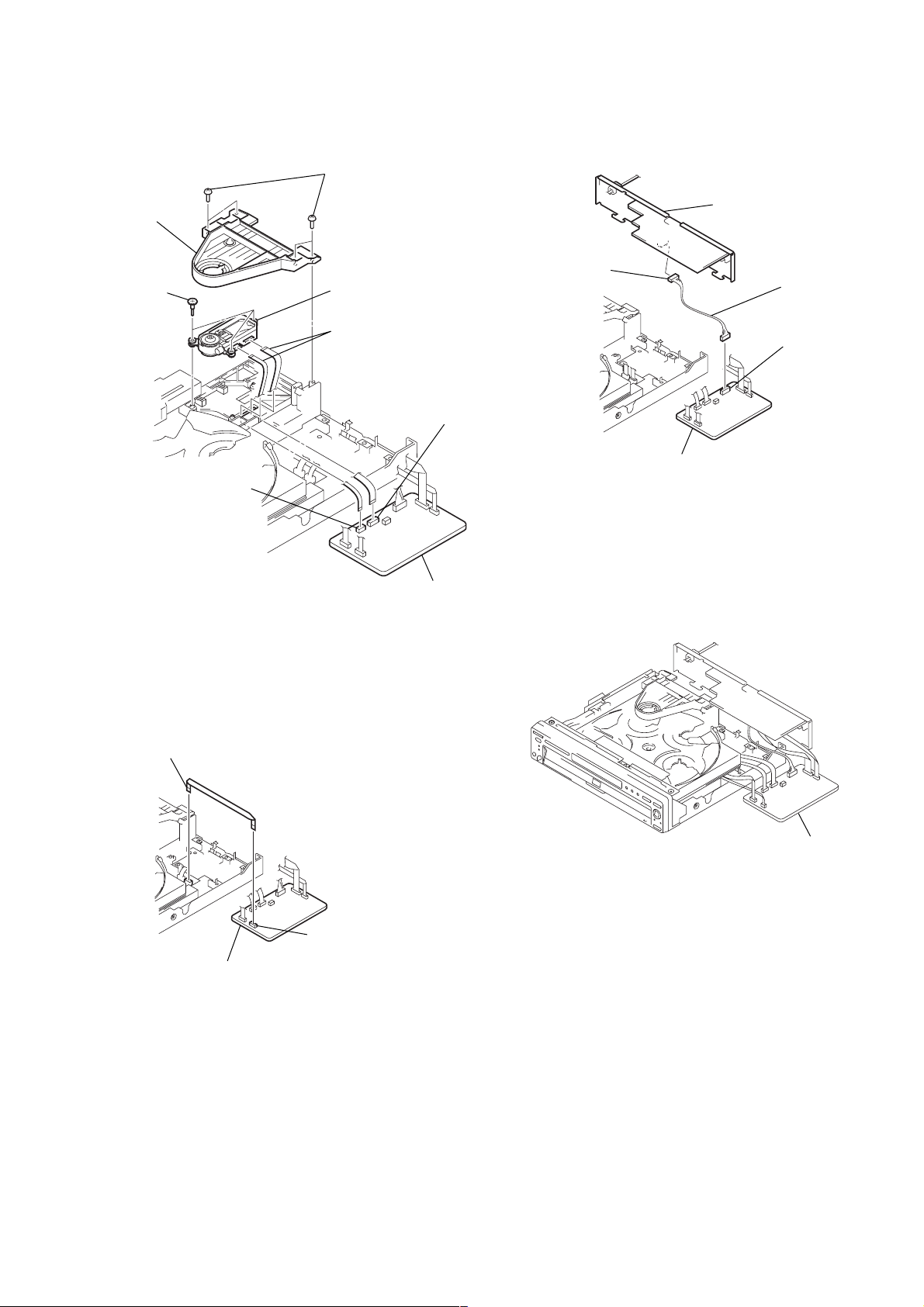
2. NOTE ON REMOVE THE UPPER CASE
4. NOTE ON MOUNTING GEARS
1) Remove seven tapping screws. (See Fig. 1)
2) Open the side of case. (See Fig. 1)
3) Remove the upper case as lift in the direction of arrow.
Three tapping screwsTwo tapping screws
Two tapping screws
Fig. 1
3. DISC REMOVAL PROCEDURE
1) Mount the gear (U/D). (See Fig. 3.)
2) Rotate the gear (U/D) in the direction of arrow.
(down position) (See Fig. 3.)
Gear (U/D)
Fig. 3
1) Insert a flat-blade screwdriver into a hole at the bottom, and
rotare the cam gear in the direction of arrow A. (See Fig. 2)
Cam gear
Table
A
Hole
Fig. 2
3) Align triangle marks of the rotary encoder. (See Fig. 4.)
4) Escape the set lever. (See Fig. 4.)
5) Connect the boss of the gear (main) with the groove of the
rotary encoder and mount the gear (main). (See Fig. 4.)
Gear (main)
BU
Boss
Set lever
Groove
Rotary encoder
– 5 –
Align triangle marks.
Fig. 4
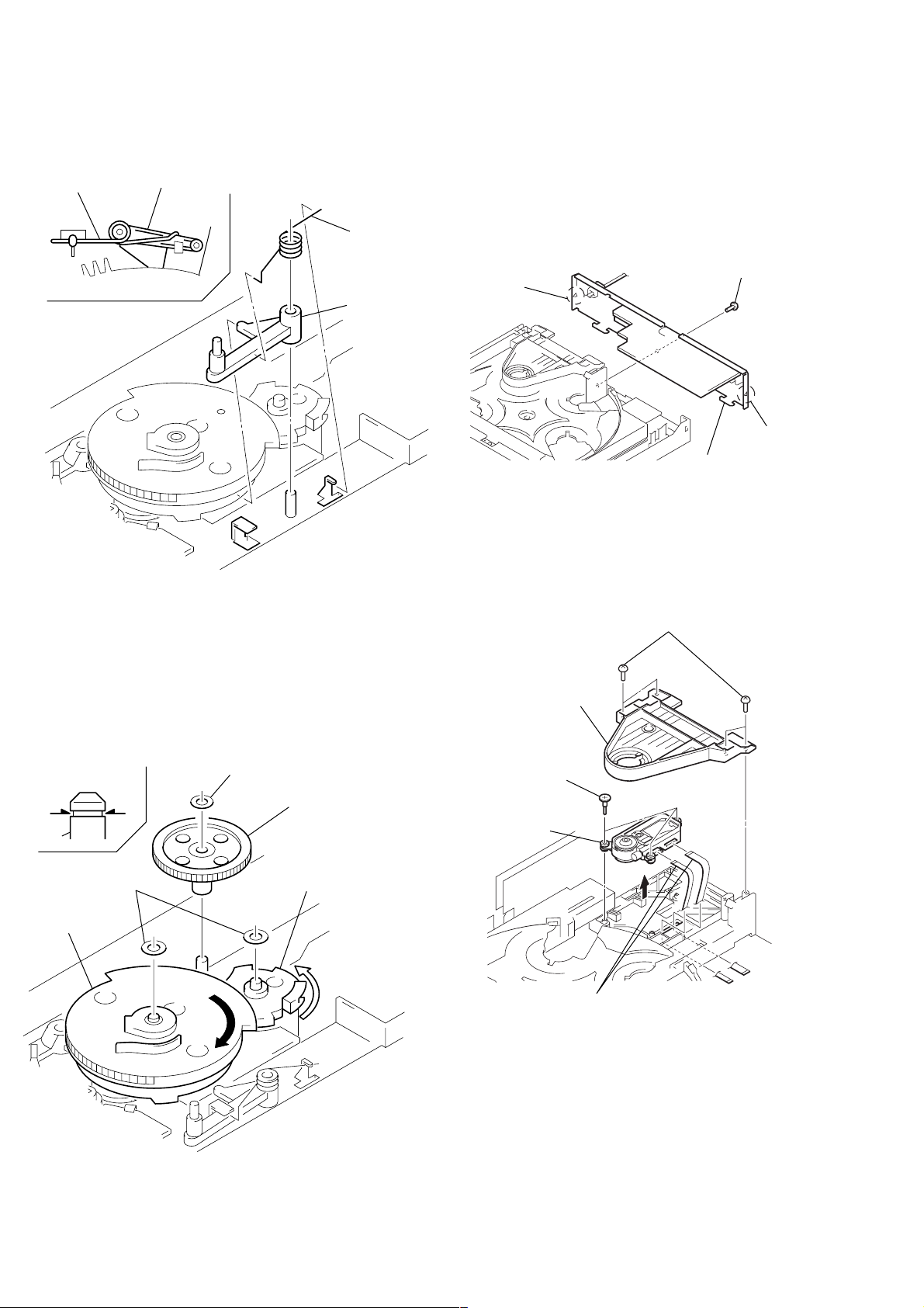
6) Mount the lock lever (See Fig. 5.)
7) Mount the spring (lock lever). (See Fig. 5.)
Spring
(lock lever)
Lock lever
Gear
(main)
Fig. 5
Spring
(lock lever)
Lock lever
5. HOW TO SERVICE MB-101 BOARD
• Use the service jig (J-6090-107-A).
1) Remove the upper case from the set. (Refer to 2-1)
2) Remove the reinforcement (C) block. (Refer to 2-2)
3) Remove the front panel section. (Refer to 2-3)
4) Remove the rear panel block as shown in Fig. 7.
1 Screw (B3)
3 Claw
2 Claw
4 Rear panel block
Fig. 7
5) Remove the MB-101 board. (Refer to 2-6)
6) Remove two flexible flat cables as shown in Fig. 8.
1 Four screws (B3)
8) Rotate the gear (main) in the direction of arrow A by 90°
turn. (Gear (U/D) is up position.) (See Fig. 6.)
9) Mount the Gear (rev). (See Fig. 6.)
10) Fix three stopper washers on the groove of shafts.
(See Fig. 6.)
Groove
*
Stopper washer
Gear (rev)
**
Shaft
Two stopper
washers
Gear (main)
A
Gear (U/D)
2 Bracket (CP)
3 Three step
screws
Optical pick-up
block
4
5 Two flexible flat cables
(FOM-001, FMM-040)
Fig. 8
Fig. 6
– 6 –
7) Set two flexible flat cables as shown in Fig. 9.
MB-101 board
5 Four screws
(B3)
4 Bracket
(CP)
3 Three step
screws
2 Optical pick-up
block
1 Two flexible flat cables
(FOM-001A, FMM-040A)
6 Connecter
(FOM-001A: CN203)
9) Set the rear panel block as shown in Fig. 11.
Rear panel block
2 Connector
(CN105)
Harness
(AM-129A)
1 Connector
(CN102)
6 Connecter
(FOM-040A: CN204)
Fig. 9
8) Set the flexible flat cables as shown in Fig. 10.
1 Flexible flat cables
(FCM-016A)
MB-101 board
MB-101 board
Fig. 11
10) Set the front panel section.
11) Set the MB-101 board as shown in Fig. 12.
Fig. 12
MB-101 board
2 Connector
(FCM-016A: CN101)
Fig. 10
– 7 –
6. CONNECTION OF SERVICE JIG
AV-60
Mechanism deck
CN301 CN301
CN-142
HARNESS 9P
FFC 26P
FFC 9P
FFC 26P (Used the set)
FFC 9P
FFC 26P
(Used the set)
CN102
CN203
CN204
CN201CN105
CN601
CN201 CN101
CN102
CN501
MB-101
FFC 13P
(Used the set)
– 8 –
SECTION 1
GENERAL
DVP-NC650V
This section is extracted from instruction
manual (3-070-514-11).
About this Manual
• Instructions in this manual describe the
controls on the remote. Yo u can also use the
controls on the player if they h ave the same
or similar names as those on the remote.
• The icons used in this manual are described
below:
z
Icon Meaning
* “DVD” may be used as a general term for DVD
VIDEOs, DVD-Rs, and DVD-RWS.
Functions available for DVD
VIDEOs or DVD-Rs/DVDRWs in Video mode
Functions available for DVDRWs in VR (Video Recording)
mode
Functions available for VIDEO
CDs or CD-Rs/CD-RWs
Functions available for Super
Audio CDs
Functions available for music
CDs or CD-Rs/CD-RWs
z More convenient features
This Player Can Play the
Following Discs
Format of discs
DVD VIDEO
DVD-RW
SACD
6
VIDEO CD
Music CD
“DVD VIDEO” and “DVD-RW” are trademarks.
Region code
Your player has a region code printed on the
back of the unit and only will play DVD
VIDEO discs (playback only) label ed with
identical reg ion codes.
CD/DVD PLAYER
AC 00V 00Hz
00W
SONY CORPORATION
ALL
X
Region code
MODEL NO.
DVP–XXXX
NO.
MADE IN JAPAN
0-000-000-00
DVDs labeled will also play on this
player.
If you try to play any other DVD, the
message “Playback prohibited by area
limitations.” will appear on the TV screen.
Depending on the DVD, no region code
indication may be labeled even though
playing the DVD is prohibited by area
restrictions.
Example of discs that the player
cannot play
The player cannot play the following discs:
• CD-ROMs (PHOTO CDs included)
• All CD-Rs/CD-RWs other than music and
VCD format CD-Rs/CD-RWs
• Data part of CD-Extras
• DVD-ROMs
• DVD Audio discs
Also, the player cannot play the following
discs:
• A DVD with a different region code (page
93).
• A disc recorded in a color system other than
NTSC, such as PAL or SECAM. (This
player conforms to the NTSC color
system.)
• A disc that has a non-standard shape (e.g.,
card, heart).
• A disc with paper or stickers on it.
• A disc that has the adhesive of cellophane
tape or a sticker still left on it.
Note
Some DVD-Rs, DVD-RWs, CD-Rs or CD-RWs
cannot be played on this player due to the recording
quality or physical condition of the disc, or the
characteristics of the recording device. DVD-RWs in
VR mode may also take time to play back due to the
recording condition.
Furthermore, the disc will not play if it has not been
correctly finalized. For more information, see the
operating instructions for the r ecording device.
Note on playback operations of DVDs
and VIDEO CDs
Some playback operations of DVDs and
VIDEO CDs may be intentionally set by
software producers. Since this player plays
DVDs and VIDEO CDs according to the disc
contents the software producers designed,
some playback features may not be available.
Also, refer to th e instructions supplied with
the DVDs or VIDEO CDs.
Copyrights
This product incorporates copyright
protection technology th at is protected by
method claims of certain U.S. pa tents, other
intellectual property rights owned by
Macrovision Corporat ion, and other r ights
owners. Use of this copyright prot ection
technology must be authorize d by
Macrovision Corporation, and is intended for
home and other limited viewing uses only,
unless otherwise authorized by Macrovisi on
Corporation. Reverse engineering or
disassembly is prohibited.
Notes about the Discs
On handling discs
• To keep the disc clean, ha ndle the disc by its
edge. Do not touch the surface.
• Do not expose the disc to direct sunlight or
heat sources such as hot air ducts, or leave
it in a car parked in direct sunlight as the
temperature may rise considerably inside
the car.
• After playing, store the disc in its case.
On cleaning
• Before playing, clean the disc with a
cleaning cloth. Wipe the disc from the
center out.
• Do not use solvents such as be nzine,
thinner, commercially available cleaners, or
anti-static spray intended for vinyl LPs.
7
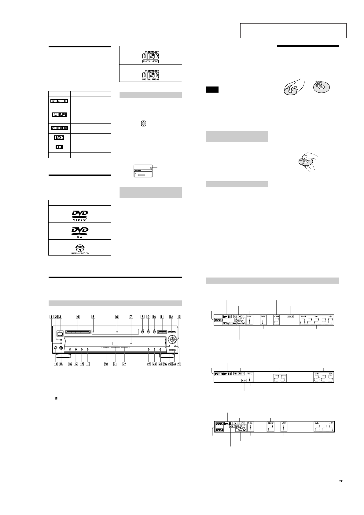
Index to Parts and Controls
For more information, refer to the pages indicated in parentheses.
Front Panel (shown with the front door open)
A BNR (Block Noise Reduction) button/
indicator (65)
B SURROUND button/indi cator (58)
C POWER (power) switch/indicator (33)
D DISC SELECT (disc select) 1 through 5
buttons (34)
E (remote sensor) (15)
F Front panel display (9)
G Disc tray (33)
H H (pla y) button (33)
I X (pause) button (34, 72)
J x (stop) button (33)
K ./> (previous/next) buttons (34)
L A (open/close) button (34)
M C/X/x/c/ENTER (enter) buttons (28)
N PHONES (pho nes) jack (33)
O LEVEL (level) control (33)
P SHUFFLE (shuffle) button (43)
Q REPEAT (repeat) button (44)
R ONE/ALL (one/all) button (40)
S LOAD (load) button (34 )
T SACD indicator
Lights up when the disc is an SACD.
U MULTI CHANNEL (multi-channel)
indicator
Lights up when:
– playing a disc that contains multiple
audio signal channels
– the disc is not inserted
V DVD indicator
Lights up when the disc is a DVD.
W TOP ME NU (top menu) button (37)
X MENU (men u) button (37)
Y ORETURN (return) button (39)
Z MEGA CONTROL (mega control)
button/indicator (75)
wj EXCHANGE (exchange) button (35)
wk DISC SKIP (disc skip) button (33)
wl DISPLAY (display) button (12)
Front Panel Display
When playing back a DVD VIDEO/DVD-RW
Disc type
Playing status
Current audio
signal (57)
All Discs mode (40)
Current play mode (40)
Current chapter (52)
Current disc (52)
Current title (52)
Lights up when you can change
the angle
When playing back a VIDEO CD (PBC)
Playing status
Disc type
All Discs mode (40)
Current disc (52)
Current play mode (40)
Current scene (52)
When playing back an SACD, CD or VIDEO CD (without PBC)
Playing status
All Discs mode (40)
Disc type*
Lights up when playing the multi-channel playback area on SACDs (38)
* When playing the SACD layer of SACD discs, the disc type is not displayed .
Current disc (52) Current index (52)
Current play mode (40)
Current track (52)
Playing time (52)
Playing time (52)
Playing time (52)
continued
8
9
1-1
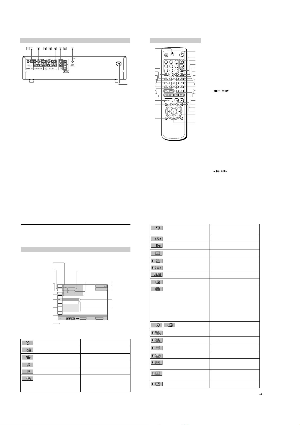
Rear Panel
A DIGITAL OUT (COAXIAL) (digital out
(coaxial)) jack (22, 24, 26)
B DIGITAL OUT (OPTICAL) (digital out
(optical)) jack (22, 24, 26)
C 5.1CH OUTPUT (5.1-channel output)
jack (22)
D AUDIO IN L/R (au dio in left/right) jacks
(75)
E LINE OUT L/R (AUDIO) (line out left/
right (audio)) 1/ 2 jacks (16, 21, 2 4, 26)
F LINE OUT (VIDEO) (line out (video)) 1/
2 jacks (16, 18)
G S VIDEO OUT (S video out) 1/2 jacks
(18)
H COMPONENT VIDEO OUT
(component video out) jac ks (18)
I MEGA CONTROL (mega con trol) jack
(75)
Remote
1
2
3
4
5
6
7
8
9
q;
qa
qs
qd
qf
qg
1 2 3
4 5 6
7 8 9
0
A TV/DVD switch (73)
B Z OPEN/CLOSE (open/close) button
(33)
C Number buttons (37)
qh
qj
qk
ql
w;
wa
ws
wd
wf
wg
wh
wj
wk
wl
e;
ea
es
ed
ef
eg
The number 5 button has a tactile dot.
D CLE AR (clear) button (41, 43 , 44, 45)
E SACD MULTI/2CH (SACD multi/2-
channel) button (38)
F SACD/CD button (38)
G AUDIO (audio) button (56)
H ANGLE ( angle) button (63)
I SHUFFLE (shuffle) button (43)
J PROGRAM (program) button (41)
K ./> PREV/NEXT (previous/
next) buttons (34)
L / SEARCH/STEP (search/
step) buttons (47)
M H PLAY (play) button (33)
The H button has a tactile dot.
N TOP MENU (top menu) button (37)
O DISPLAY (display) button (12)
P ?/1 (on/standby) button (33)
Q VOL (vol ume) +/– buttons (73)
The + button has a tactile dot.
R TV/VIDEO/BNR (TV/video/BNR)
button (65, 73)
S WIDE MODE (wide mode)/DVE
(Digital Video Enhancer ) button (67, 73)
T ENTER (enter) button (28)
U DISC SKIP (disc skip) button (34)
V SEARCH MODE (search mod e) button
(48)
W TIME/TEXT (time/text) button (52)
X SUBTITLE (subtitle) button (64)
Y A-B button (45)
Z REPEAT (repeat) button (44)
wj REPLAY (replay) button (34)
wk SURROUND (surroun d) button (58)
wl / SCAN/SLOW buttons (47)
e; x STOP (stop) button (34)
ea X PAUSE (pause) button (34)
es MENU (menu) button (37)
ed C/X/x/c butto ns (28)
ef ORETURN (return) button (39)
eg ENTER (enter) button (28)
10
Guide to the Control Menu Di splay
Use the Control Menu to select a function that you would like to use. The Control Menu display
appears when the DISPLAY button is pressed. For details, please refer to the page in parentheses.
Control Menu
Currently playing disc
number
Currently playing title
number (VIDEO CD/SACD/
CD: track number)
Currently playing chapter
number (VIDEO CD/SACD/
CD: index number)
Icon of selected Control
Menu item
Control Menu items
Function name of selected
Control Menu item
Operation message
List of Control Menu Items
DISC (page 48) Selects the disc to be played.
TITLE (page 48)/SCENE (page 48)/
TRACK (page 48)
CHAPTER (page 48)/INDEX (page
48)
TRACK (page 48) Selects the track to be played.
INDEX (page 48) Selects the index to be played.
TIME/TEXT (page 48) Checks the elapsed time and the remaining
12
Playing time
Total number of titles or tracks
recorded
Total number of
chapters or indexes
recorded
1
)
1 2 ( 2 7
)
1 8 ( 3 4
T
1 : 3 2 : 5 5
OFF
OFF
1: ENGLISH
2: FRENCH
3: SPANISH
SUBTITLE
Select: Cancel:
ENTER RETURN
Selects the title, scene, or track to be played.
Selects the chapter or index to be play ed.
playback time.
Input the time code for picture and mu sic
searching.
Displays the DVD or SACD/CD text.
Playback status
N
(
Pause,
PLAY
DVD VIDEO
Playback, X
x
Stop, etc.)
Type of disc
being played
back
Current
setting
Options
ORIGINAL/PLAY LIST (page 37) Selects the type of titles (DVD-RW) to be
AUDIO (page 56) Changes the audio setting.
MULTI/2CH (page 38) Selects the playback area on SACDs when
SUBTITLE (page 64) Displays the subtitles.
ANGLE (page 63) Changes the angle.
SURROUND (page 58) Selects the surround functions.
ADVANCED (page 55) Checks the i nformation (bit rate or layer) on
PARENTAL CONTROL (page 68) Set to prohibit playback on this player.
SETUP (page 77) QUICK Setup (page 28)
ONE/ALL DISCS (page
40)
PROGRAM (page 41) Selects the discs, title, chapter, or track to play
SHUFFLE (page 43) Plays the disc s, title, chapter, or track in a
REPEAT (page 44) Plays the discs, entire disc (all titles/all tracks),
A-B REPEAT (page 45) Specifies the parts you want to play repeated ly.
BNR (page 65) Adjusts the picture quality by re ducing the
VIDEO EQUALIZER (page 66) Adjusts the video signal from the player. You
DIGITAL VIDEO ENHANCER (page
67)
played, the ORIGINAL one, or an edited PLAY
LIST.
available.
Changes the subtitle language.
the disc while playing a DVD.
Use Quick Setup to choose the desired
language for the on-screen displa y, the aspect
ratio of the TV, the audio output, and the
appropriate speaker settings.
CUSTOM Setup
In addition to the Quick Setup setting, you can
adjust other various settings.
RESET
Returns the settings in “SETUP” to the default
setting.
Selects One Disc or All Discs mode.
in the order you want.
random order.
or one title/chapter/track repeatedly.
“block noise” or mosai c like patterns that
appear on your TV screen.
can select the picture quality that best suits the
program you are watching.
Exaggerates the outline of the image to
produce a sharper pictu re.
continued
11
13
1-2
VIEWER (page 50) Divides the screen into 9 sub-screens to help
z
Each time you press DISPLAY, the Control Menu display changes as fo llows:
Control Menu display 1
,
m
Control Menu display 2
m
ADVANCED display (Appears if you select any setting other than “OFF.” See page 55.)
m
Control Menu display off
z
The Control Menu icon indicator lights up in green when you select any item except
“OFF” (“SURROUND,” “PROGRAM,” “SHUFFLE,” “REPEAT,” “A-B REPEAT,” “BNR,” “DIGITAL VIDEO
ENHANCER” only). The “ANGLE” indicator lights up in green only when the angles can be changed. T he “VIDEO
EQUALIZER” indicator lights up in green when any setting other than “STANDAR D” is selected.
you find the scene you want quickly.
t
Getting Started
Quick Overview
A quick overview presented in this chapter will give you enough information to start using the
player for your enjoyment. To use the surround sound features of this player, refer to “Hookups”
on page 18.
Notes
• You cannot connect thi s player to a TV that does not have a video input jack.
• Be sure to turn off the power of each component before connecting.
Step 1: Unpacking
Check that you have the followi ng items:
• Audio/video cord (pin plug x 3 y pinplug x 3) (1)
• Remote commander (remote) RMT-D133A (1)
• Size AA (R6) batteries (2)
• S VIDEO cord (1)
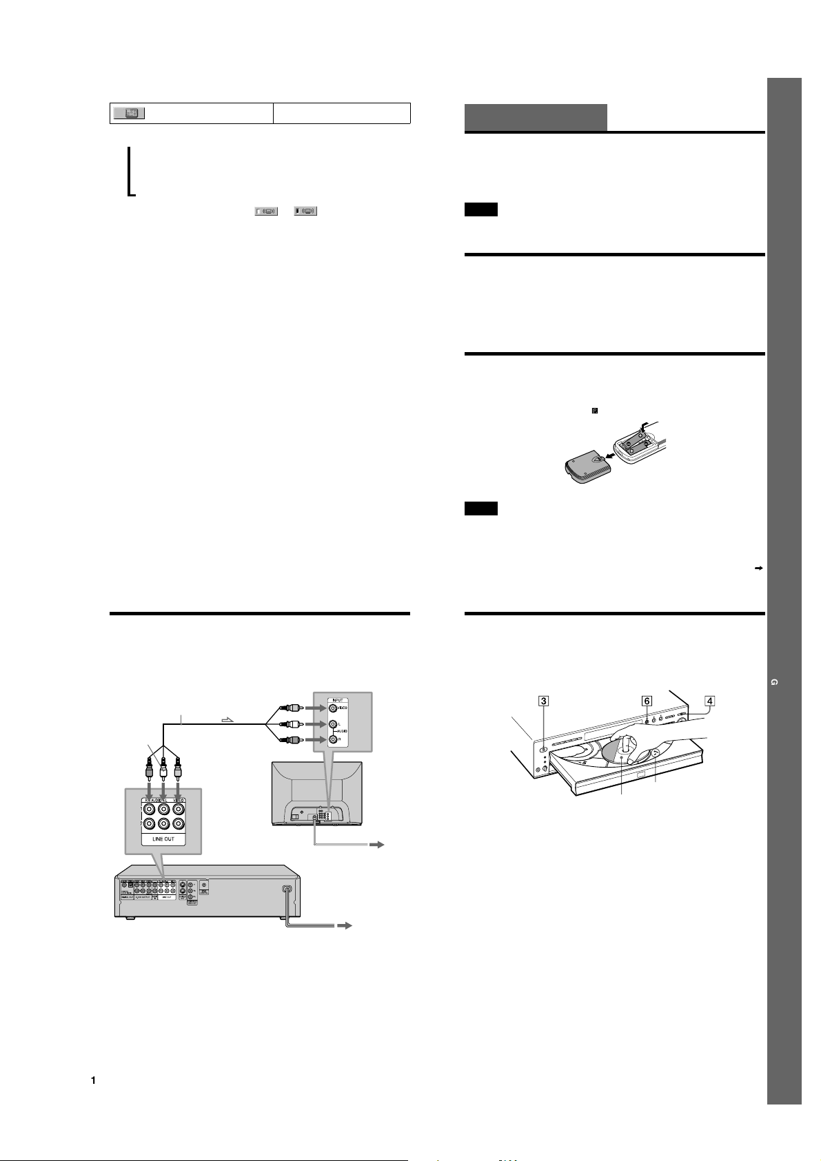
Step 2: Inserting Batteries into the Remote
You can control the player using the supplied remote. Insert two size AA (R6) batt eries by
matching the 3 and # ends on the batteries to the markings inside the compartment. When using
the remote, point it at the remote sensor on the player.
Getting Started
14
Step 3: TV Hookups
Connect the supplied audio/video cord and power cord in the order (1~3) shown below. Be
sure to connect the power cord last.
1 Audio/video cord
(supplied)
to LINE OUT L/R
(AUDIO) 1
(white)
(red)
l: Signal flow
to LINE OUT
(VIDEO) 1
(yellow)
When connecting to a wide screen TV
Depending on the disc, the image may not fit your TV screen.
If you want to change the aspect ratio, plea se refer to page 79.
to video input
to audio input
SACD/DVD Player
(yellow)
(white)
(red)
(yellow)
(white)
(red)
2 Power source
3 Power source
Notes
• Do not leave the remote in an extremely hot or humid place.
• Do not drop any foreign obj ect into the remote casing, particularly when replacing the batteries.
• Do not expo se the remote sensor to direct light from the su n or lighting apparatus. Doing so may cause a
malfunction.
• If you d o not use the remote for an extended period of time, remove the batteries to avoid possibl e damage from
battery leakage and corrosion.
continued
15
15
Step 4: Playing a Disc
A Turn on the TV.
B Switch the input selector on the TV to the player.
TV
Disc compartment number
With the playback side facing down
C Press POWER on the player.
D Press
A
on the player to open the disc tray.
E Place the disc on the tray with the playback side facing down.
F Press
H
.
The disc tray closes and the player begi ns playing the disc.
After Step 6
Depending on the disc, a menu may be displayed on the TV screen. If so, select the item you wa nt
from the menu and play the DVD (page 37) or VIDEO CD disc (page 39).
To stop playing
Press x.
To take out the disc
Press A.
To turn off the player
Press ?/1 on the remote. The play er is set to standby mode and the power indicat or lights up in
red. Press POWER on the player to turn off completely.
Getting Started
16
1-3
17
17
Hookups
Hooking Up the Player
Follow Steps 1 to 4 to hook up and adjust the settings of the player.
Before you start, turn off the power, check that you have all of the supplied accessories, and insert
the batteries into the remote (page 15).
Notes
• Plug cords securely to prevent unwanted noise.
• Refer to the ins tructions supplied with the components to be connected.
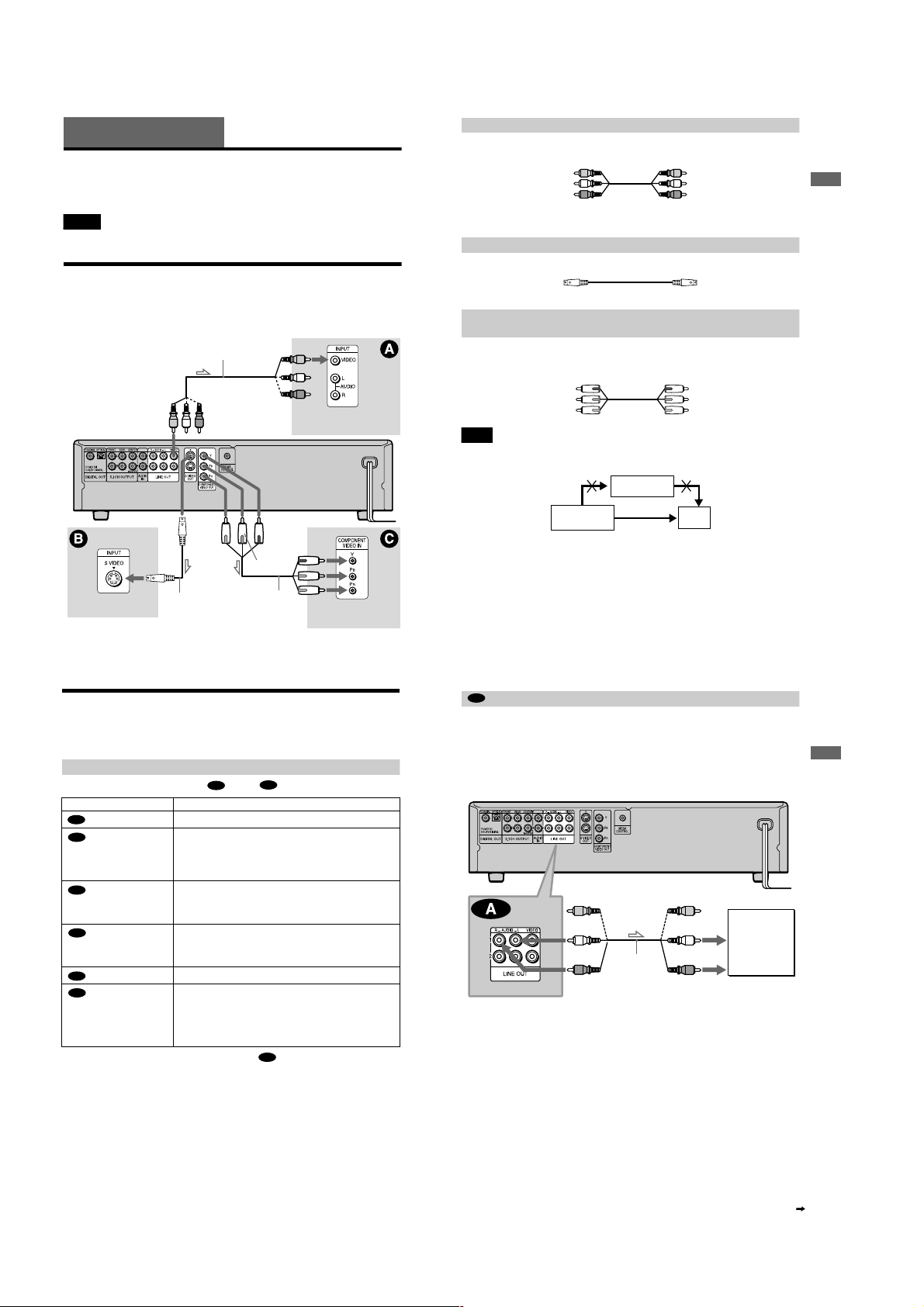
Step 1: Connecting the Video Cords
Connect this player to yo ur TV monitor, projector, or AV ampli fier (receiver) using a video cord.
Select one of the patterns A through C, accordi ng to the input jack on your TV monitor,
projector, or AV amplifier (receiver).
Audio/video cord
(supplied)
(yellow)
SACD/DVD player
(yellow)
TV, projector, AV
amplifier (receiver)
A If you are connecting to a video input jack
Connect the yellow plugs of the audio/video cord (supplied) to the yellow (vi deo) jacks. You will
enjoy standard quality images.
Yellow (Video)
White (L)
Red (R)
Yellow
White (L)
Red (R)
Use the red and white plugs to connect to the audio input jacks (page 21).
B If you are connecting to an S VIDEO input jack
Connect the S VIDEO cord (supplied). You will enjoy high quality images.
B If you are connecting to a mon itor, proj ector, or A V ampli fie r (recei ver) ha ving
component video input jacks (Y, P
Connect the component via the COMPONENT VIDE O OUT jacks using the component video
cord (not supplied) or th ree video cords (not supplied) of th e same kind and length. You will enj oy
accurate color reproduction and high quality im ages.
Green
Blue
Red
B
, PR)
Green
Blue
Red
Note
Do not connect your player to a VCR. You may not receive a clear image on the TV screen if you p ass the player
signals via the VCR.
VCR
Hookups
(green)
(blue)
Component video
cord (not supplied)
TV, projector, AV
amplifier (receiver)
TV, projector, AV
amplifier (receiver)
l: Signal flow
S VIDEO cord
(supplied)
(red)
18
Step 2: Connecting the Audio Cords
Refer to the chart below to select the connection that best suits y our system. The surround effects
you will enjoy depend on the connections and components you use.
Select a connection
Select one of the following co nnections, through .
Connection Components to be connected
(page 21)
A
(page 22)
B
(page 22)
B
(page 24)
C
(page 24)
C
(page 26)
D
z
To enjoy SACD Multi or 96 kHz/24 bit sound, use connection .
* Manufactured under license from Dolby Laboratories. “Dolby,” “Pr o Logic,” and the double-D symbol are
trademarks of Dolby Laboratories. Confidenti al unpublished works. © 1992-1997 Dolby Laboratories. All rights
reserved.
** Manufactured under license from Digital Theater Systems, Inc. US PAT. No. 5,451,942 and other world-wide
patents issues and pending. “DTS” and “DTS Digital surround” are trademarks of Dig ital Theater Systems, Inc.
© 1996 Digital Theater Systems, Inc. All rights reserve d.
A
TV (stereo)
AV amplifier (receiver) having 5.1ch input jacks
• 4 speaker s
(front L and R, rear L and R)
• 6 speaker s
(front L and R, center, rear L and R, subwoofer)
AV amplifier (receiver) having a Dolby* Digital or DTS** decoder,
and a digital input jack
• 6 speaker s
(front L and R, center, rear L and R, subwoofer)
Stereo amplifier (receiver)
(having L and R audio input jacks only, or having a digital in put jack)
• 2 speaker s
(front L and R)
MD deck/DAT deck
AV amplifier (receiver) with a Dolby Surround (Pro Logic) decoder
(having L and R audio input jacks only, or having a digital in put jack)
• 3 speaker s
(front L and R, and rear (monaural))
• 6 speaker s
(front L and R, center, rear L and R, subwoofer)
D
B
(green)
(blue)
(red)
A
Connecting to your TV
SACD/DVD player
Connect directly.
This connection will use your TV speakers for sound.
xRecommended surround sound effects for this connection
• TVS DYNAMIC (page 58)
• TVS WIDE (page 58)
SACD/DVD player
(yellow)
(white)
Audio/video
cord
(supplied)
(red)
l: Signal flow
The yellow plug is used for video sig nals (page 18).
TV
(yellow)
(white)
(red)
to audio input
19
Hookups
TV
20
1-4
continued
21
 Loading...