

Sony DVPCX-777-ES Service manual
DVP-CX777ES
Outputs
(Jack name: Jack type/Output level/Load
impedance)
LINE OUT AUDIO L/R 1/2: Phono jack/
2Vrms/10kilohms
DIGITAL OUT (OPTICAL): Optical
output jack/–18 dBm (wave length:
660 nm)
DIGITAL OUT (COAXIAL): Phono jack/
0.5 Vp-p/75 ohms
5.1CH OUTPUT: Phono jack/2 Vrms/
10 kilohms
COMPONENT VIDEO OUT (Y, P
B/CB
,
P
R/CR
): Phono jack/Y: 1.0 Vp-p/PB/CB,
P
R/CR
: interlace*=0.648 Vp-p,
progressive or interlace**=0.7 Vp-p/
75 ohms
*BLACK LEVEL is ON
** BLACK LEVEL is OFF
LINE OUT VIDEO 1/2: Phono jack/
1.0 Vp-p/75 ohms
S VIDEO OUPUT 1/2: 4-pin mini DIN/
Y: 1.0 Vp-p/C: 0.286 Vp-p /75 ohms
S-LINK (CONTROL S IN): Mini jack
•Remote commander (remote) (1)
•Size AA (R6) batteries (2)
× 3) (1)
SERVICE MANUAL
Ver 1.1 2004.09
E
NERGY STARR is a U.S. registered mark.
E
NERGY STARR Partner, Sony
As an
Corporation has determined that this product
meets the
energy efficiency.
E
NERGY STARR guidelines for
SPECIFICATIONS
US Model
Canadian Model
Model Name Using Similar Mechanism NEW
CD/DVD Mechanism Type CDM62-DVBU26
Base Unit Name DVBU26
Optical Pick-up Name KHM-290AAA
System
Laser: Semiconductor laser
λ = 780 nm for CD
λ = 650 nm for SA-CD and DVD
Emission duration: continuous
Signal format system: NTSC
Audio characteristics
Frequency response: DVD VIDEO (PCM
96 kHz): 2 Hz to 44 kHz (44 kHz: –2 dB
±1 dB), Super Audio CD: 2 Hz to
100 kHz (50kHz: –3dB ±1 dB), CD:
2Hz to 20 kHz (±0.5 dB)
Signal-to-noise ratio (S/N ratio): 115 dB
(LINE OUT AUDIO L/R 1/2 jacks only)
Harmonic distortion: 0.003 %
Dynamic range: DVD VIDEO/Super Audio
CD: 103 dB, CD: 99 dB
Wow and flutter: Less than detected value
(±0.001% W PEAK)
General
Power requirements:
120 V AC, 60 Hz
Power consumption: 24 W
Dimensions (approx.): 430 × 189 × 545 mm
Mass (approx.): 10 kg (22 lb 1 oz)
Operating temperature: 5 ° C to 35 ° C
Operating humidity: 25 % to 80 %
Supplied accessories
•Audio/video cord (pinplug × 3 y pinplug
Specifications and design are subject to
change without notice.
1
1
/
2
× 21
/
2
(17 × 7
depth) incl. projecting parts
(41
°
F to 95°F)
in.) (width/height/
CD/DVD PLAYER
9-961-043-02 Sony Corporation
2004I05-1 Audio Group
C 2004.09 Published by Sony Engineering Corporation

DVP-CX777ES
SELF DIAGNOSIS FUNCTION
Self-diagnosis Function
(When letters/numbers appear in the
display)
When the self-d iagn osis fu ncti on i s a cti vat ed
to prevent the player from malfunctioning, a
five-character serv ice nu mber (e.g., C 13 50)
with a combination of a letter and four d igi ts
appears on the screen and th e front panel
display. In this case , check the following
table.
C:13:50
First three
characters of
the service
number
C 13 The disc is dirty .
C 31 The disc is not inserted
C 32 The front cover
E XX
(xx is a number)
Cause and/or corrective
action
, Clean the disc with a soft
cloth.
correctly.
, Re-insert the disc
correctly.
automaticall y opens and the
player enters standby mode .
, Check that there is
nothing wrong inside the
rotary table, such as a
fallen disc. After you
have checked the inside
of the rotary table and
resolved any possible
problems, press H.
To prevent a malfunction, the
player has performed th e
self-diagnosis function.
, Contact your nearest
Sony dealer or loca l
authorized Sony serv ice
facility and give the 5character ser vice numb er.
Example: E 61 10
Note: Refer to the “4. TEST MODE” (page 23)
for another self-diagnosis function.
2
DVP-CX777ES
r
Notes on chip component replacement
•Never reuse a disconnected chip component.
• Notice that the minus side of a tantalum capacitor may be damaged by heat.
Flexible Circuit Board Repairing
•Keep the temperature of the soldering iron around 270 ˚C during repairing.
• Do not touch the soldering iron on the same conductor of the
circuit board (within 3 times).
• Be careful not to apply force on the conductor when soldering
or unsoldering.
SAFETY CHECK-OUT
After correcting the original service problem, perform the following safety check before releasing the set to the customer:
Check the antenna terminals, metal trim, “metallized” knobs,
screws, and all other exposed metal parts for AC leakage.
Check leakage as described below.
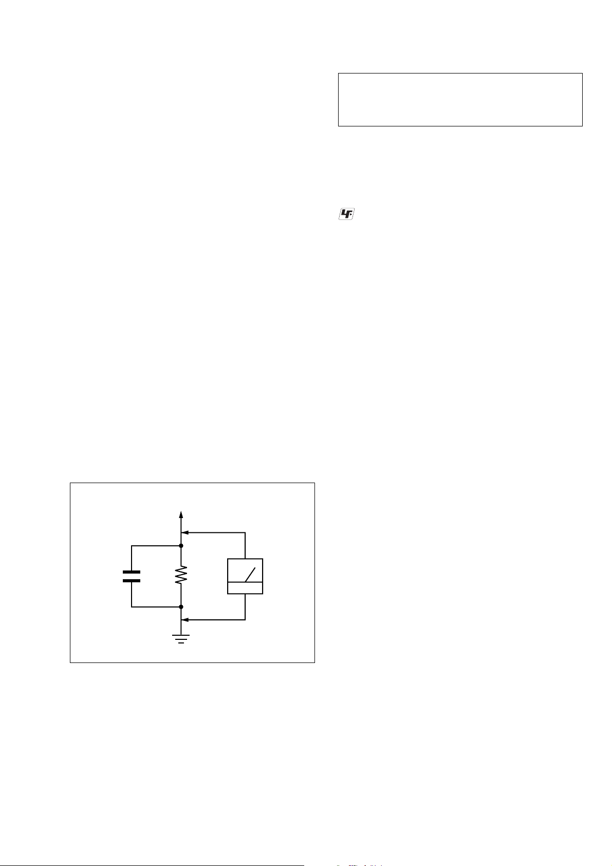
LEAKAGE TEST
The A C leakage fr om any exposed metal part to earth ground and
from all exposed metal parts to any exposed metal part having a
return to chassis, must not exceed 0.5 mA (500 microamperes.).
Leakage current can be measured by any one of three methods.
1. A commercial leakage tester, such as the Simpson 229 or RCA
WT -540A. Follo w the manufacturers’ instructions to use these
instruments.
2. A battery-operated AC milliammeter. The Data Precision 245
digital multimeter is suitable for this job.
3. Measuring the voltage drop across a resistor by means of a VOM
or battery-operated A C voltmeter . The “limit” indication is 0.75
V, so analog meters must have an accurate low-voltage scale.
The Simpson 250 and Sanwa SH-63Trd are examples of a passive VOM that is suitable. Nearly all battery operated digital
multimeters that have a 2 V A C range are suitable. (See Fig. A)
CAUTION
Use of controls or adjustments or performance of procedures
other than those specified herein may result in hazardous radiation exposure.
UNLEADED SOLDER
Boards requiring use of unleaded solder are printed with the leadfree mark (LF) indicating the solder contains no lead.
(Caution: Some printed circuit boards may not come printed with
the lead free mark due to their particular size)
: LEAD FREE MARK
Unleaded solder has the following characteristics.
• Unleaded solder melts at a temperature about 40 ˚C higher than
ordinary solder.
Ordinary soldering irons can be used but the iron tip has to be
applied to the solder joint for a slightly longer time.
Soldering irons using a temperature regulator should be set to
about 350 ˚C.
Caution: The printed pattern (copper foil) may peel away if the
heated tip is applied for too long, so be careful!
• Strong viscosity
Unleaded solder is more viscou-s (sticky, less prone to flow)
than ordinary solder so use caution not to let solder bridges occur such as on IC pins, etc.
• Usable with ordinary solder
It is best to use only unleaded solder but unleaded solder may
also be added to ordinary solder.
To Exposed Metal
Parts on Set
1.5 k
0.15 µF
Fig. A. Using an AC voltmeter to check AC leakage.
SAFETY-RELATED COMPONENT WARNING!!
COMPONENTS IDENTIFIED BY MARK 0 OR DOTTED
LINE WITH MARK 0 ON THE SCHEMATIC DIAGRAMS
AND IN THE PARTS LIST ARE CRITICAL TO SAFE
OPERATION. REPLACE THESE COMPONENTS WITH
SONY PARTS WHOSE PART NUMBERS APPEAR AS
SHOWN IN THIS MANUAL OR IN SUPPLEMENTS PUBLISHED BY SONY.
Ω
Earth Ground
AC
voltmete
(0.75 V)
ATTENTION AU COMPOSANT AYANT RAPPORT
À LA SÉCURITÉ!
LES COMPOSANTS IDENTIFIÉS P AR UNE MARQUE 0
SUR LES DIAGRAMMES SCHÉMATIQUES ET LA LISTE
DES PIÈCES SONT CRITIQUES POUR LA SÉCURITÉ
DE FONCTIONNEMENT. NE REMPLACER CES COMPOSANTS QUE PAR DES PIÈCES SONY DONT LES
NUMÉROS SONT DONNÉS DANS CE MANUEL OU
DANS LES SUPPLÉMENTS PUBLIÉS PAR SONY.
3
DVP-CX777ES
Example of discs that the player
cannot play
The player cannot play the following discs:
•All CD-ROMs (i ncluding PHOTO C D s) /
CD-Rs/CD-RWs other than th ose recorded
in the following formats:
–music CD format
–video CD format
–MP3 format that co nforms to ISO9660*
Level 1/Level 2, or its extended format,
Joliet
•Data part of CD-Extras
• DVD-ROMs
• DVD Audios
*A logical format of files and folde rs on CD-
ROMs defined by ISO (International Standard s
Organization).
Also, the player cannot play the following
discs:
•A DVD VIDEO with a different region
code.
•A disc recorded in a color system other than
NTSC, such as PAL or SECAM (this player
conforms to the NTSC color system).
•A disc that has a non-st andard shape (e.g.,
card, heart).
•A disc with paper or stickers on it.
•A disc that has the adhesive of cellophan e
tape or a sticker still left on it.
Notes
•Note about DVD-RWs/DVD-Rs, DVD+RWs/
DVD+Rs, or CD-Rs/CD-RWs.
Some DVD-RWs/DVD-Rs, DVD+RWs/
DVD+Rs, or CD-Rs/CD-RWs cannot be played
on this player due to the recording quality or
physical condition of the disc, or th e
characteristics of the recording device and
authoring software. Also, images in DVD-RWs
with CPRM* protection may not be played if they
contain a copy protection sign al. “ Cop yr ight
lock” appe ars on the scr een. For more
information, see the operating instructions for the
recording device.
Note that discs cr eated in the Packet Write format
cannot be played.
*CPRM (Content Protection for Recordable
Media) is a coding technology that protects
copyright for images.
•Music discs encoded with co pyright protecti on
technologies
This product is designed to playback discs that
conform to the Compact Disc (CD) standard.
Recently, various music discs encoded wit h
copyright protection technologies are marketed
by some record companies. Please be aware that
among those discs, there are some that do not
conform to the CD standard and may not be
playable by this product.
Note on playback operations of
DVDs and VIDEO CDs
Some playback operations of DVDs and
VIDEO CDs may be intentionally set by
software producers. Since this player pla ys
DVDs and VIDEO CDs according to the disc
contents the software producer s designed,
some playback features may not be available.
Also, refer to the instructions supplied with
the DVDs or VIDEO CDs.
Copyrights
This product incorporates copyrigh t
protection technology that is protected by
U.S. patents and other intellectual property
rights. Use of this copyright protection
technology must be authorized by
Macrovision, and is intended for home and
other limited viewing uses only unless
otherwise authorized by Macrovision.
Reverse engineer i ng or disassembly is
prohibited.
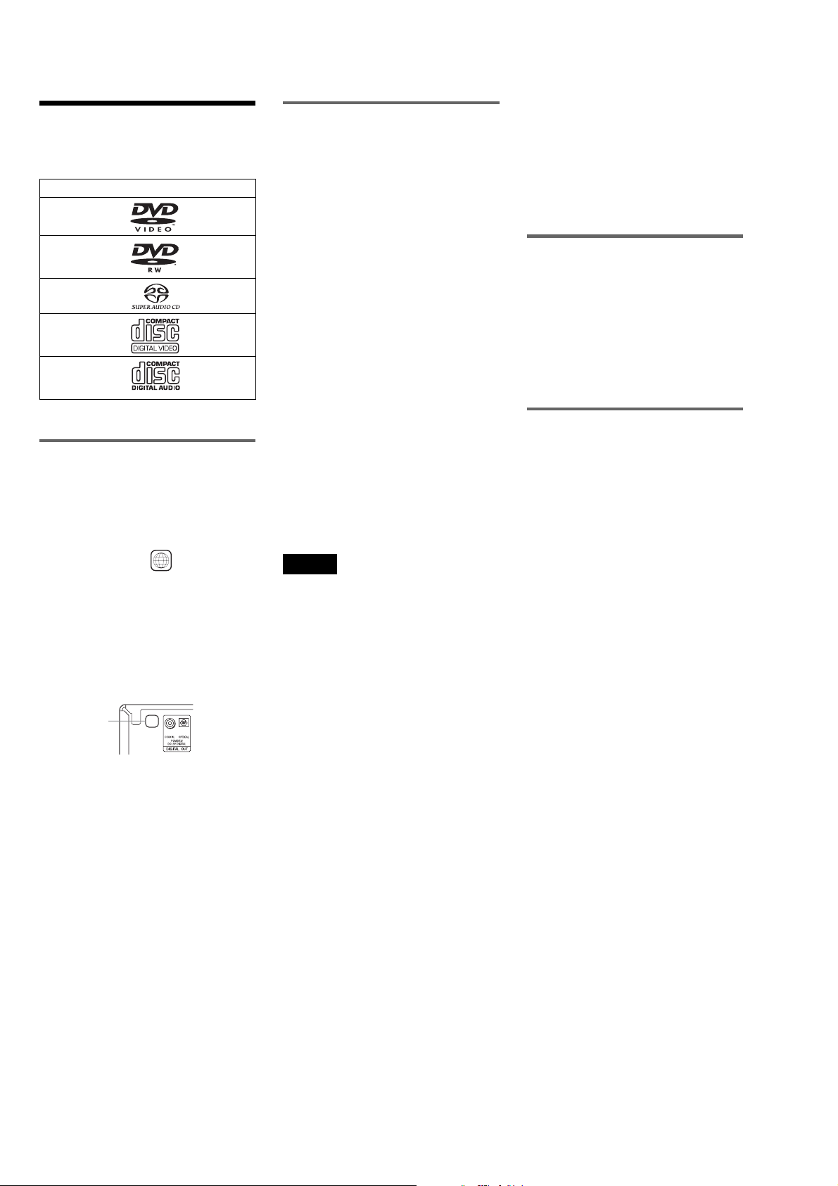
This Player Can Play the
Following Discs
Format of discs
DVD VIDEO
DVD-RW
Super Audio CD
VIDEO CD
Music CD
“DVD VIDEO” and “DVD-RW” are
trademarks.
Region code
Your player has a region code printed on the
back of the unit and will only play DVD
VIDEOs (playback only) labeled with
identical region codes . This syste m is used to
protect copyrights.
DVD VIDEOs labeled will also play on
this player.
If you try to play any other DVD VIDEO, the
message “Playback pr ohibited by area
limitations.” will appear on the TV screen.
Depending on the DVD VIDEO, no region
code indication may be labeled even though
playing the DVD VIDEO is prohibited by
area restrictions.
Region code
ALL
X
4

TABLE OF CONTENTS
DVP-CX777ES
SELF DIAGNOSIS FUNCTION.................................... 2
1. SERVICING NOTES ............................................... 6
2. GENERAL ................................................................... 10
3. DISASSEMBLY
3-1. Disassembly Flow ........................................................... 11
3-2. Case (ES) Assy................................................................ 12
3-3. MB Board ........................................................................ 12
3-4. AV Board ......................................................................... 13
3-5. Bracket (L)/(R)................................................................ 13
3-6. Front Panel Section ......................................................... 14
3-7. Cover (PT)/(CDM).......................................................... 14
3-8. DVBU26 Assy ................................................................. 15
3-9. Power Block, Power Transformer (T102) ...................... 15
3-10. Table (400) Assy ............................................................. 16
3-11. Door Block, Base (Door) Assy ....................................... 16
3-12. DC Motor (Door) (M603) ............................................... 17
3-13. Holder (Table Sensor 400).............................................. 17
3-14. D. SENS OUT Board, D. SENS IN Board..................... 18
3-15. Pop-up (400) Assy........................................................... 18
3-16. Door SW Board............................................................... 19
3-17. Lock SW Board, Loading SW Board ............................. 20
3-18. CD/DVD Mechanism Deck Block
(CDM62-DVBU26) ........................................................ 21
3-19. Motor (400) Assy (Loading) (M602)/(Table) (M601),
Loading Motor Board ..................................................... 21
3-20. Optical Pick-up (KHM-290AAA) .................................. 22
4. TEST MODE.............................................................. 23
5. MECHANICAL ADJUSTMENTS....................... 45
6. ELECTRICAL ADJUSTMENTS......................... 46
7. DIAGRAMS
7-1. Block Diagram – RF Section – ...................................... 50
7-2. Block Diagram – SERVO/CHANGER Section – ......... 51
7-3. Block Diagram – AUDIO Section – .............................. 52
7-4. Block Diagram – VIDEO Section – .............................. 53
7-5. Block Diagram
– PANEL/POWER SUPPLY Section – .......................... 54
7-6. Note for Printed Wiring Boards and
Schematic Diagrams ....................................................... 55
7-7. Schematic Diagram – MB Board (1/15) – .................... 57
7-8. Schematic Diagram – MB Board (2/15) – .................... 58
7-9. Schematic Diagram – MB Board (3/15) – .................... 59
7-10. Schematic Diagram – MB Board (4/15) – .................... 60
7-11. Schematic Diagram – MB Board (5/15) – .................... 61
7-12. Schematic Diagram – MB Board (6/15) – .................... 62
7-13. Schematic Diagram – MB Board (7/15) – .................... 63
7-14. Schematic Diagram – MB Board (8/15) – .................... 64
7-15. Schematic Diagram – MB Board (9/15) – .................... 65
7-16. Schematic Diagram – MB Board (10/15) – .................. 66
7-17. Schematic Diagram – MB Board (11/15) – .................. 67
7-18. Schematic Diagram – MB Board (12/15) – .................. 68
7-19. Schematic Diagram – MB Board (13/15) – .................. 69
7-20. Schematic Diagram – MB Board (14/15) – .................. 70
7-21. Schematic Diagram – MB Board (15/15) – .................. 71
7-22. Printed Wiring Board
– MB Board (Component Side) –................................... 72
7-23. Printed Wiring Board
– MB Board (Conductor Side) –..................................... 73
7-24. Printed Wiring Board – DRIVER Board – .................... 74
7-25. Schematic Diagram – DRIVER Board –....................... 75
7-26. Printed Wiring Boards
– MOTOR/SWITCH Section –....................................... 76
7-27. Schematic Diagram – MOTOR/SWITCH Section – .... 77
7-28. Printed Wiring Boards – SENSOR Section –................ 78
7-29. Schematic Diagram – SENSOR Section – .................... 79
7-30. Printed Wiring Board
– AV Board (Component Side) – .................................... 80
7-31. Printed Wiring Board
– AV Board (Conductor Side) – ...................................... 81
7-32. Printed Wiring Board
– RS-232C Board – ......................................................... 82
7-33. Schematic Diagram – AV (1/3)/RS-232C Boards – ...... 83
7-34. Schematic Diagram – AV Board (2/3) – ........................ 84
7-35. Schematic Diagram – AV Board (3/3) – ........................ 85
7-36. Printed Wiring Board
– PANEL-L Board (Component Side) –......................... 86
7-37. Printed Wiring Board
– PANEL-L Board (Conductor Side) – .......................... 87
7-38. Schematic Diagram – PANEL-L Board (1/2) – ............ 88
7-39. Schematic Diagram – PANEL-L Board (2/2) – ............ 89
7-40. Printed Wiring Boards – PANEL Section – .................. 90
7-41. Schematic Diagram – PANEL Section –....................... 91
7-42. Printed Wiring Board – POWER Board – ..................... 92
7-43. Schematic Diagram – POWER Board –........................ 93
7-44. IC Pin Function Description .......................................... 102
8. EXPLODED VIEWS
8-1. Overall Section...............................................................128
8-2. Front Panel Section ........................................................ 129
8-3. Power Block Section......................................................130
8-4. Table Section.................................................................. 131
8-5. Chassis Section .............................................................. 132
8-6. Base (Door) Section ....................................................... 133
8-7. CD/DVD Mechanism Deck Section-1
(Pop-up Block) ............................................................... 134
8-8. CD/DVD Mechanism Deck Section-2
(Pulley Block) ................................................................135
8-9. CD/DVD Mechanism Deck Section-3
(Lever, Holder Block) .................................................... 136
8-10. CD/DVD Mechanism Deck Section-4
(Gear, Motor Block)....................................................... 137
8-11. Optical Pick-up Section (DVBU26) .............................. 138
9. ELECTRICAL PARTS LIST .............................. 139
5
DVP-CX777ES
Ver 1.1
SECTION 1
SERVICING NOTES
NOTES ON HANDLING THE OPTICAL PICK-UP
BLOCK OR BASE UNIT
The laser diode in the optical pick-up block may suffer electrostatic break-down because of the potential difference generated
by the charged electrostatic load, etc. on clothing and the human
body.
During repair, pay attention to electrostatic break-down and also
use the procedure in the printed matter which is included in the
repair parts.
The flexible board is easily damaged and should be handled with
care.
NOTES ON LASER DIODE EMISSION CHECK
The laser beam on this model is concentrated so as to be focused
on the disc reflective surface by the objective lens in the optical
pick-up block. Therefore, when checking the laser diode emission, observe from more than 30 cm away from the objectiv e lens.
NOTE OF REPLACING THE MB BOARD
When replacing the MB board, since the adjustment value is not
set up correctly, “Drive Auto Adjustment” can’t be performed.
In this case, initialize Memory in the following procedures.
Procedure:
1. Set the test mode. (See page 23)
2. Press the [2] key of the remote commander, and set the “DRIVE
MANUAL OPERATION”. (See page 29)
3. Press the [6] key of the remote commander, and set the “2-6,
Memory Check”. (See page 32)
4. Press the [CLEAR] key of the remote commander, and initialize Memory.
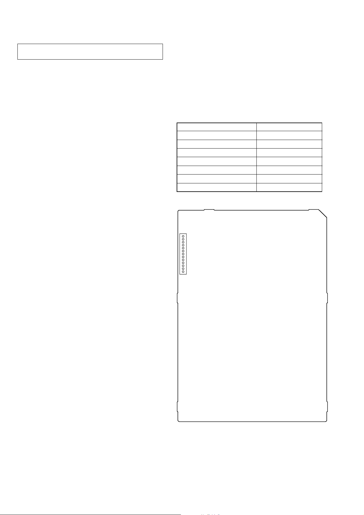
CHECK OF POWER BOARD WITH THE POWER ON
It is possible to analyze the defect with only POWER board power
ON.
Procedure:
1. Set to power OFF state.
2. Remove the connector from CN201 on the POWER board.
3. Short between CN201 pin 1 (P-CONT) and CN201 pin qa
(EVER+3.3V) on the POWER board.
4. Turn the power ON.
5. Confirm that the voltage value of CN201 each pin on the
POWER board satisfy following value .
CN201 Pin Voltage Value
pin 2 (EVER–11V) –11V
pin 3 (SW–11V) –11V
pin 6, 7 (SW+11V) +11V
pin 8 (SW+3.3V) +3.3V
pin qa (EVER+3.3V) +3.3V
pin qs (SW+5V) +5V
pin qd (EVER+5V) +5V
– POWER Board (Conductor Side) –
13
CN201
1
6
DVP-CX777ES
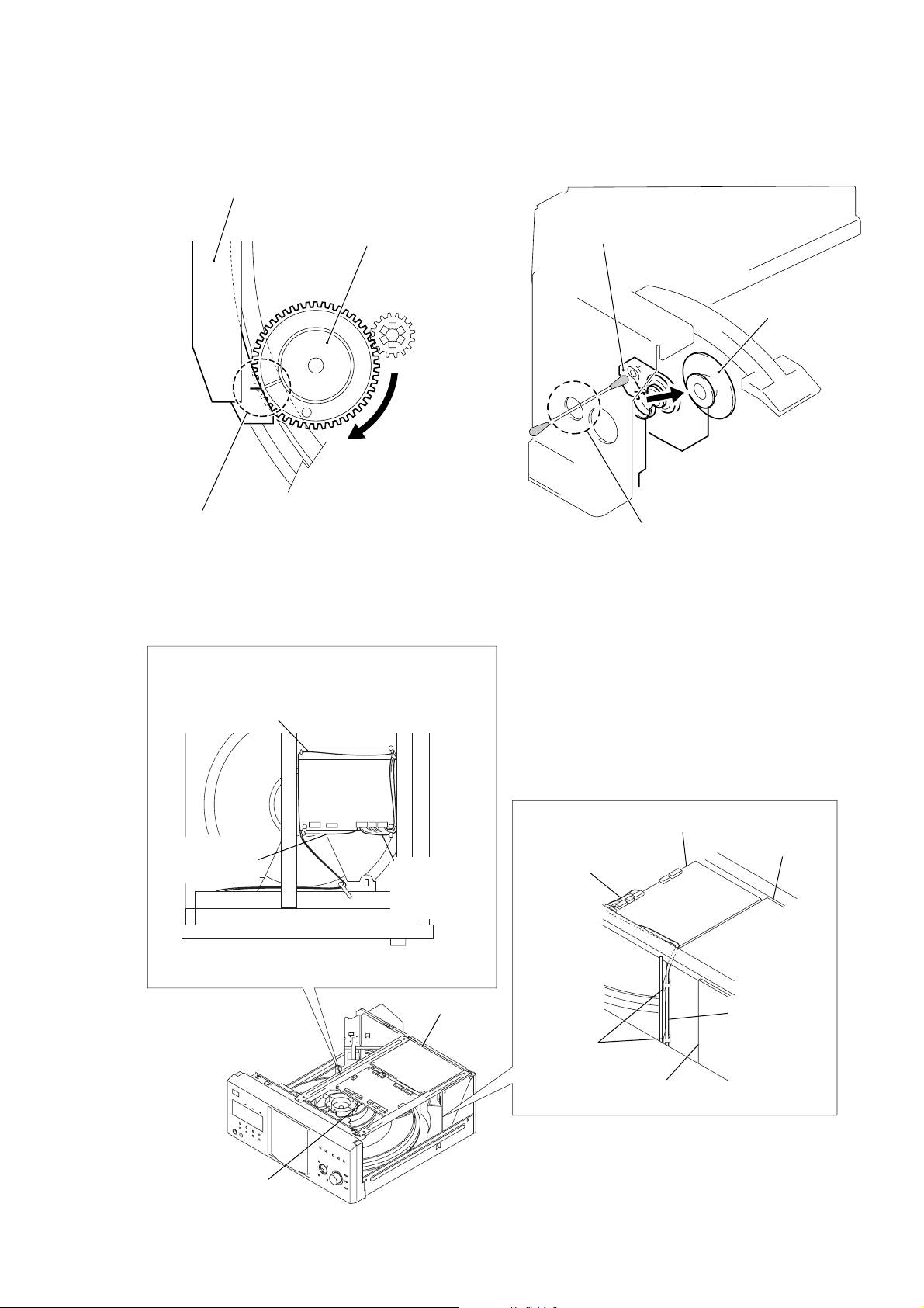
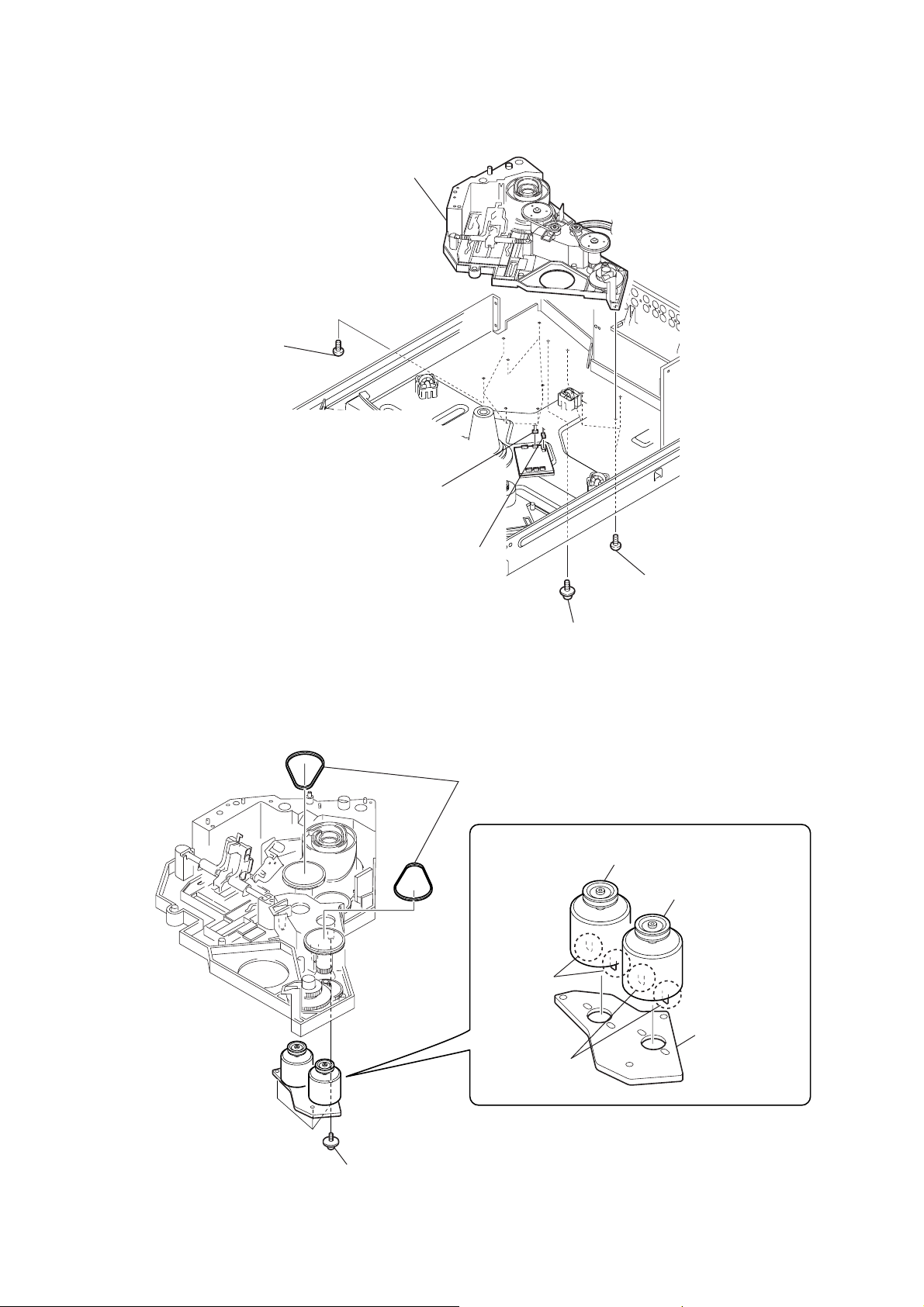
ALIGNMENT OF GEAR (CAM) PHASE WITH DOOR
ASSY
door assy
gear (cam)
Align a slit of door assy with a marking on
the bottom land of gear tooth when the gear
is rotated fully in arrow direction, as shown.
CLEANING OF OPTICAL PICK-UP
optical pick-up
pulley assy
Remove the pulley assy, and
clean the lens of optical pick-up
through this hole.
NOTE FOR INSTALLATION
It takes care that the cables doesn’t hang down.
cable
(AV board to panel-L board)
cable
(MB board to
led board)
– Front side –
AV board
MB board
cables
(MB board to
driver board,
sensor board)
AV board
cables
(MB board to
driver board,
sensor board)
locking wire
saddle
MB board
AV board
cables
(MB board to
driver board,
sensor board)
MB board
power block
7
DVP-CX777ES
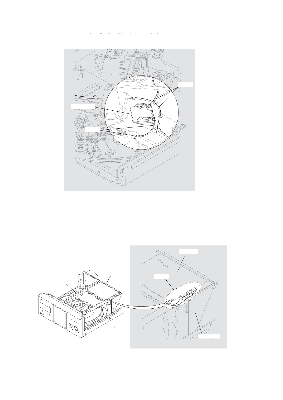
When installing the cables, it is made to make it crawl in a chassis.
cables
driver board
cables
It is made to contact and for there not to be a power block and cables.
AV board
MB board
power block
AV board
cables
power block
8

SERVICE POSITION
– MB board –
panel-L board
(CN1005)
DVP-CX777ES
Connect the jig (J-2501-086-A) to
MB board (CN102) and
panel-L board (CN1005).
MB board (CN102)
– Optical pick-up block –
optical pick-up
(DVBU26)
9
DVP-CX777ES
SECTION 2
GENERAL
This section is extracted from
instruction manual.
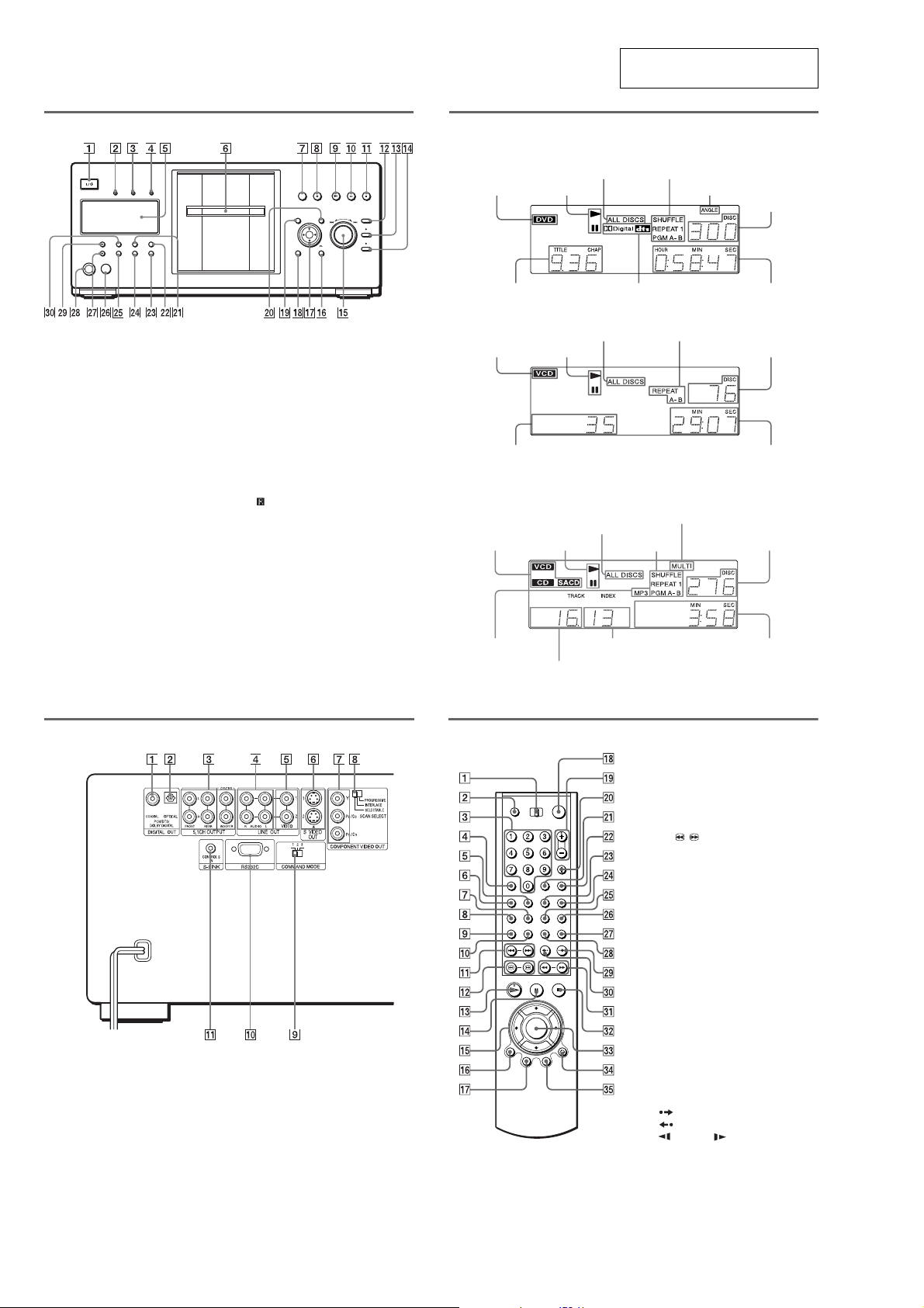
Front panel
A [/1 (on/standby) button
B PROGRESSIVE indicator
—Lights up when the player outputs
progressive signals.
C SACD (Super Audio CD) indicator
Lights up when:
—playing a Super Audio CD.
— no disc is i nserted.
D MULTI CHANNEL indicator
Lights up when:
—Playing a track or chapter that
contains three or more audio signal
channels.
—no disc is inserted.
E Front panel display
F Front cover
G OPEN/CLOSE button
A
DISC EJECT button
H
I N (play) button
J X (pause) button
K x (stop) button
L +100 button
M DISC CHANGE button/indicator
N DIRECT SEARCH button/indicator
O .–/>+/ENTER
(previous/next/enter) dial
O
RETURN button
P
Q C/X/x/c/ENTER buttons
R DISPLAY button
S TOP MENU button
T MENU button
U VIDEO CONTROL button
V SURROUND button
W ONE/ALL DISCS button
X FOLDER button
Y LOAD button
Z (remote sensor)
wj VIDEO OFF indicator
wk KEYBOARD jack
wl FL OFF button/indicator
e; TIME/TEXT button
Front panel display
When playing back a DVD VIDEO/DVD-RW
Current play
Disc type
Current title and chapter
All discs mode
Playing status
Current audio signal
When playing back a VIDEO CD with Playback Control (PBC)
All discsmode
Disc type
Current scene
Playing status
When playing back a CD, Super audio CD, DATA CD (MP3 audio), or VIDEO CD (without
PBC)
Disc type
(“SACD” lights up
during HD playba c k)
All discsmode
Playing status Current disc
mode
Current play mode
Current play
mode
Lights up when you can
change the angle
Playing time
Current disc
Playing time
Lights up when playing the multi-channel
playback area onSuper Audio CDs
Current disc
Rear panel
A DIGITAL OUT (COAXIAL) jack
B DIGITAL OUT (OPTICAL) jack
C 5.1CH OUTPUT jacks
D LINE OUT AUDIO L/R 1/2 jacks
E LINE OUT VIDEO 1/2 jacks
F S VIDEO OUT 1/2 jacks
*This port is intended for future applications.
G COMPONENT VIDEO OUT (Y, P
C
B
, PR/CR) jacks
H COMPONENT VIDEO OUT/SCAN
SELECT switch
I COMMAND MODE switch
J RS232C jack*
K S-LINK/CONTROL S IN jack
Lights up when
playing MP3 audio
tracks
Current index (CD, Super Audio CD,
VIDEO CD) or track(DATA CD)
Current track (CD, Super Audio CD,
VIDEO CD) or album (DATACD)
Playing time
Remote
G SUBTITLE button
H AUDIO button
I PICTURE NAVI (picture navigation)
button
J REPEAT button
K ./> PREV/NEXT (previous/
next) buttons
L c / C SEARCH/STEP
buttons
M H PLAY button
The H button has a tactile dot.*
N X PAUSE button
O C/X/x/c buttons
P DISPLAY/FILE button
Q TOP MENU/EDIT button
R [/1 (on/standby) button
S VOL (volume) +/– buttons
The + button has a tactile dot.*
T TV/VIDEO/DISC SKIP + button
U ENTER button
V WIDE MODE/DISC SKIP – button
W FOLDER button
X PICTURE MEMORY button
Y ANGLE button
B
/
A TV/DISC EXPLORER/DVD switch
B OPEN/CLOSE button
C Number but tons
The number 5 button has a tac ti l e dot.*
D CLEAR button
E SUR (surround) button
F VIDEO CONTROL button
Z TIME/TEXT button
wj SACD/CD (Super Audio CD/CD)
button
wk SACD MULTI/2CH (Super Audio CD
multi/2 channel) button
wl INSTANT SEARCH button
e; INSTANT REPLAY butto n
ea m/M SCAN/SLOW
buttons
es x STOP button
ed ENTER button
ef O RETURN button
eg MENU/SORT button
*Use the tactile dot as a reference when operat in g
the player.
10
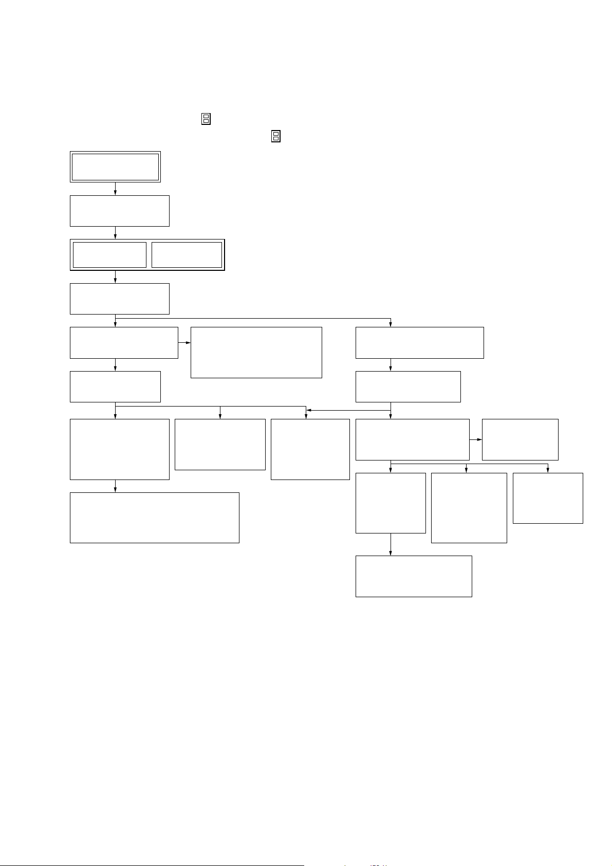
SECTION 3
DISASSEMBLY
• This set can be disassembled in the order shown below.
3-1. DISASSEMBLY FLOW
Note 1: The process described in can be performed in any order.
Note 2: Without completing the process described in , the next process can not be performed.
Set
3-2. CASE (ES) ASSY
(Page 12)
DVP-CX777ES
3-3. MB BOARD
(Page 12)
3-5. BRACKET (L)/(R)
(Page 13)
3-7. COVER (PT)/(CDM)
(Page 14)
3-8. DVBU26 ASSY
(Page 15)
3-18. CD/DVD
MECHANISM
DECK BLOCK
(CDM62-DVBU26)
(Page 21)
3-19. MOTOR (400) ASSY
(LOADING) (M602)/(TABLE) (M601),
LOADING MOTOR BOARD
(Page 21)
3-4. AV BOARD
(Page 13)
3-20. OPTICAL
3-9. POWER BLOCK,
POWER TRANSFORMER
(T102)
(Page 15)
PICK-UP
(KHM-290AAA)
(Page 22)
3-17. LOCK SW
BOARD,
LOADING
SW BOARD
(Page 20)
3-6. FRONT PANEL SECTION
(Page 14)
3-10. TABLE (400) ASSY
(Page 16)
3-11. DOOR BLOCK,
BASE (DOOR) ASSY
(Page 16)
3-12. DC
MOTOR
(DOOR)
(M603)
(Page 17)
3-14. D. SENS
OUT
BOARD,
D. SENS IN
BOARD
(Page 18)
3-16. DOOR SW
BOARD
(Page 19)
3-15. POP-UP
(400)
ASSY
(Page 18)
3-13. HOLDER
(TABLE SENSOR 400)
(Page 17)
11
DVP-CX777ES
Note: Follow the disassembly procedure in the numerical order given.
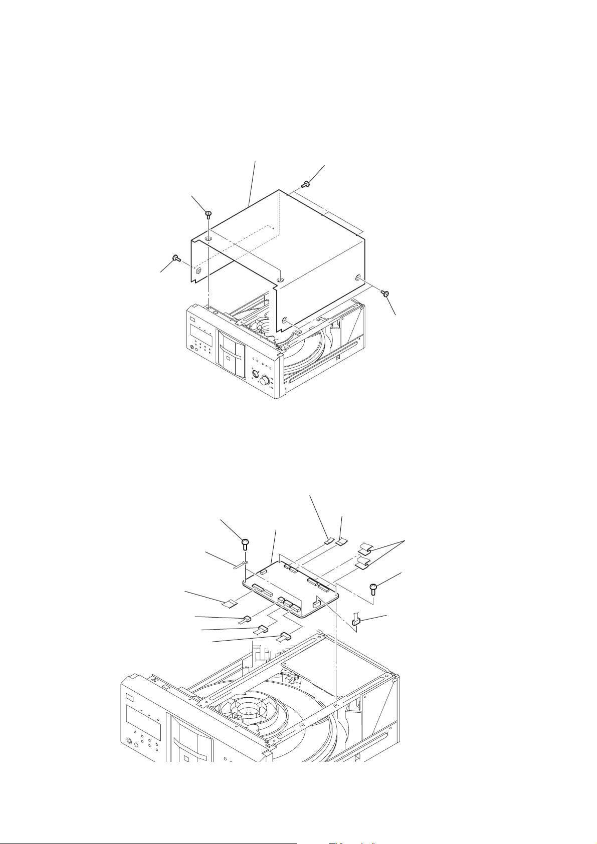
3-2. CASE (ES) ASSY
5
case (ES) assy
4
two flat head screws
1
two flat head screws
3
three flat head screws
3-3. MB BOARD
1
8
9
two harnesses
wire (flat type)
(19 core) (CN102)
two screws
(BVTP 3
2
two flat head screws
3
wire (falt type)
(9 core) (CN204)
2
×
8)
qs
MB board
wire (flat type)
(26 core) (CN203)
4
q;
two wires (flat type)
(23 core: CN601,
27 core: CN501)
two screws
(BVTP 3
×
8)
12
5
connector (CN105)
6
connector (CN103)
7
connector (CN106)
qa
connector (CN101)
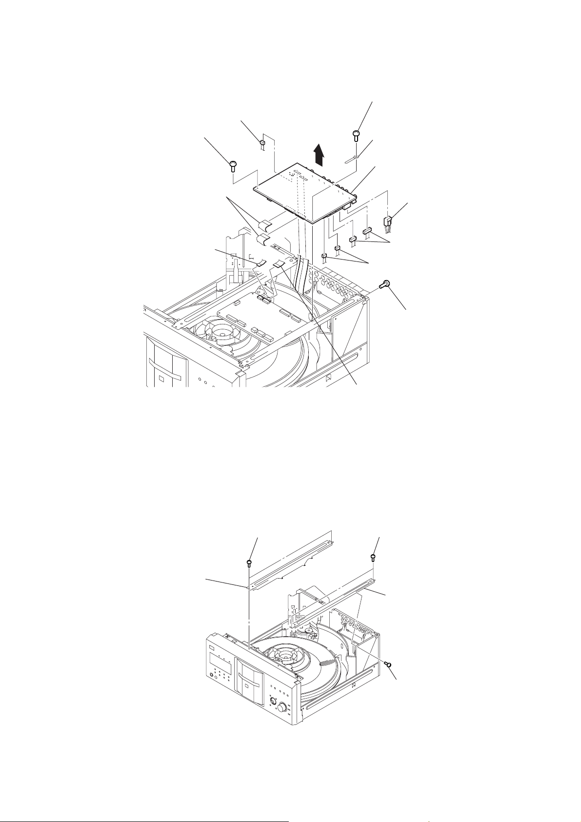
3-4. AV BOARD
4
screw (BVTP 3 × 8)
9
connector (CN201)
5
+BV sumitite (B3)
6
harness
DVP-CX777ES
8
two wires (flat type)
(23 core: CN202,
27 core: CN203)
2
wire (flat type)
(9 core) (CN204)
3-5. BRACKET (L)/(R)
7
qd
AV board
qa
q;
two connectors
(CN206, 207)
1
wire (flat type)
(26 core) (CN203)
qs
connector (CN204)
two connectors
(CN205, 208)
3
eight screws
(BV/ring)
2
bracket (L)
1
two screws
(BVTP 3
3
×
8)
two screws
(BVTP 3
5
bracket (R)
4
screw
(BVTP 3
×
8)
×
8)
13
DVP-CX777ES
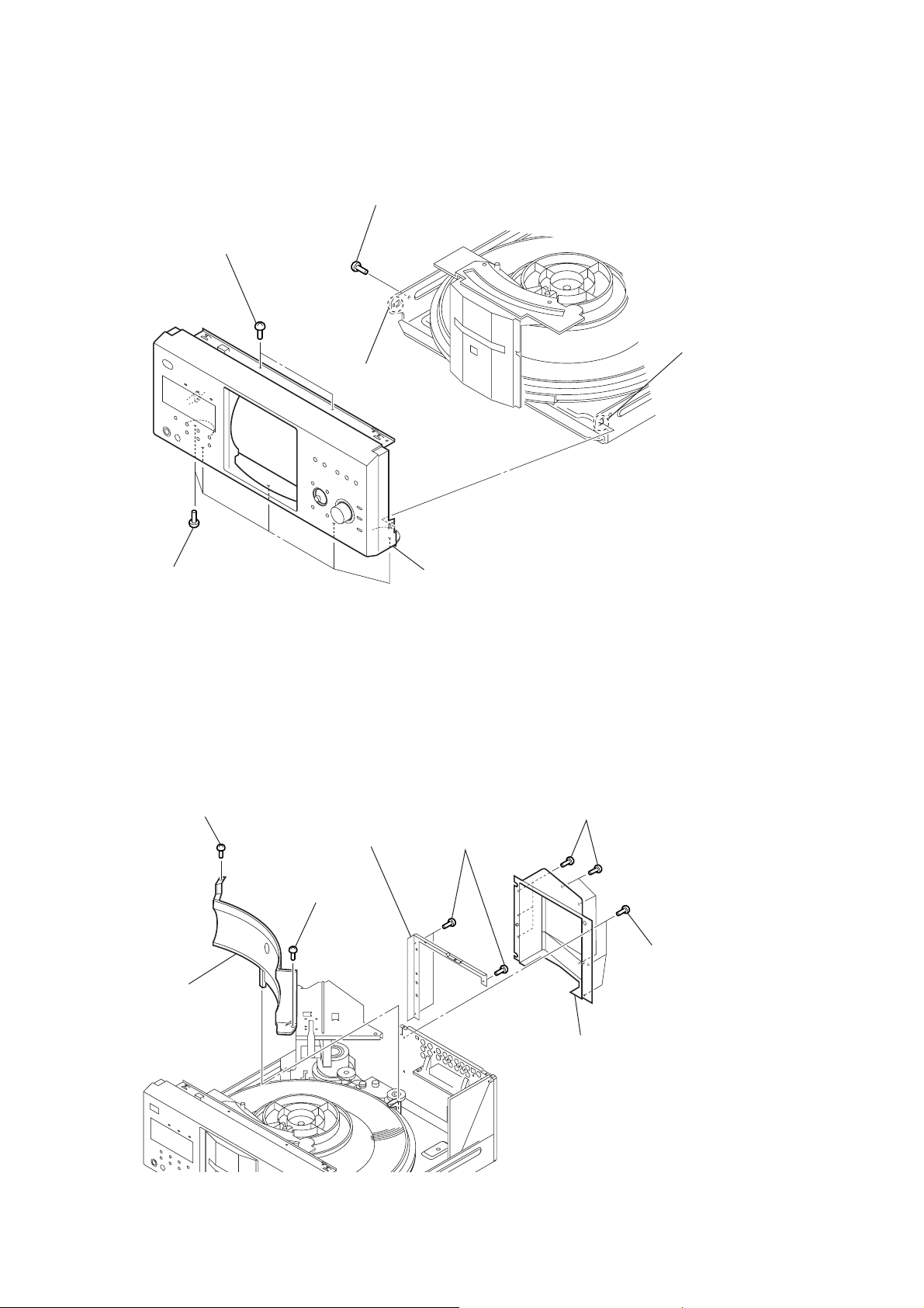
s
3-6. FRONT PANEL SECTION
3
two screws
(BVTP 3
×
8)
2
screw
(BVTP 3
5
claw
×
8)
4
claw
1
five screws
(BV/ring)
3-7. COVER (PT)/(CDM)
1
screw
(BVTP 3
3
cover (PT)
6
front panel section
4
×
8)
2
screw
(BVTP 3
8
bracket (CDM)
×
8)
7
three screws
(BV/ring)
six screws
(BV/ring)
5
three screw
(BV/ring)
14
6
cover (CDM)
DVP-CX777ES
y
s
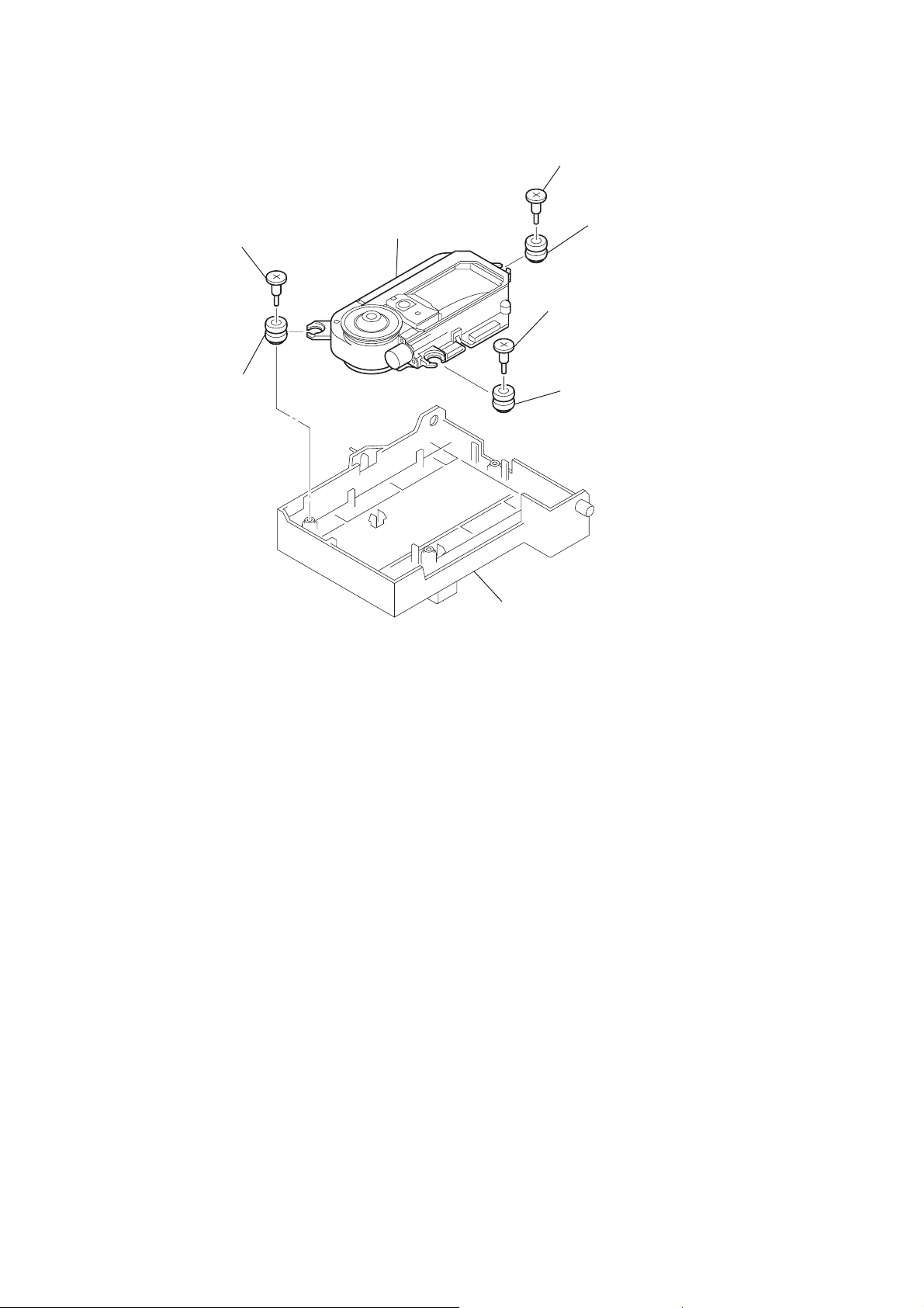
3-8. DVBU26 ASSY
6
torsion holder
(magnet) block
8
torsion spring
(MG)
5
bracket (top 400) block
7
washer
1
three screws
(BVTP 3
q;
8 washer
×
8)
2
screw (BVTP 3 × 8)
3
two screws
(BVTP 3
×
8)
9
DVBU26 ass
3-9. POWER BLOCK, POWER TRANSFORMER (T102)
q;
power transformer (T102)
9
5
connector
(CN102)
four screws
(BVTP 3
×
8)
7
screw
(BVTP 3
×
8)
1
two screws
(BVTP 3
4
screw
(BVTP 3
×
8)
3
rear panel block
×
8)
2
two screw
(BV/ring)
4
connector
(CN101)
6
two screws
(BVTP 3
8
power block
×
8)
15

DVP-CX777ES
)
)
3-10. TABLE (400) ASSY
1
screw (M3 × 14)
2
guide block (door)
Note for installation
When installing the guide (door),
align the positions as shown.
3
table (400) assy
3-11. DOOR BLOCK, BASE (DOOR) ASSY
2
3
cover (table)
three screws (BVTP 3 × 8)
7
base (door) assy
4
10 washer
1
connector (CN904
16
4
door block
5
two screws (BVTP 3 × 8)
6
eight screws (BVTP 3 × 8
3-12. DC MOTOR (DOOR) (M603)
d
1
belt
3
Remove two
solderings.
5
DC motor (door) (M603)
4
DVP-CX777ES
door motor boar
3-13. HOLDER (TABLE SENSOR 400)
2
connector
(CN83)
5
screw
(PTTWH 3
6
×
6)
two claws
1
four screws
(BVTP 3
4
×
8)
sensor board
3
two connectors
(CN81, CN82)
6
claw
2
two screws (BVTP 3 × 8)
7
holder
(table sensor 400)
17
DVP-CX777ES
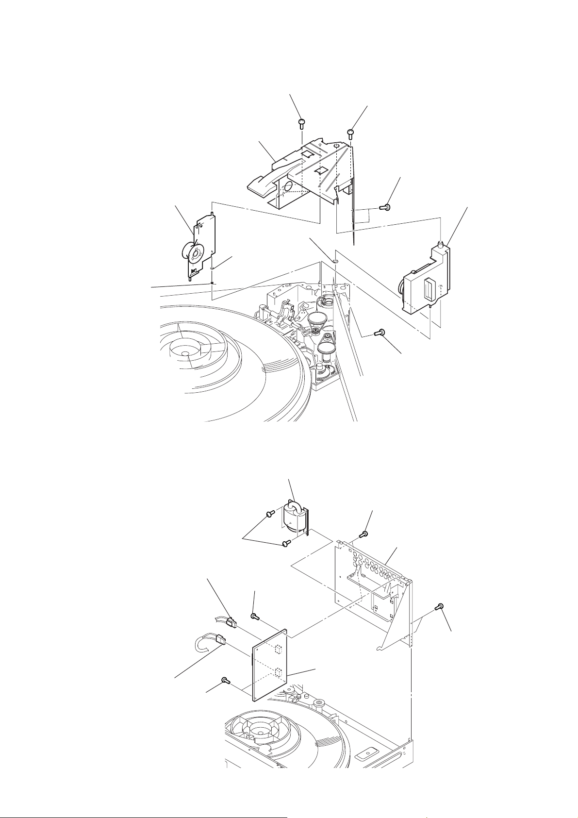
)
3-14. D. SENS OUT BOARD, D. SENS IN BOARD
6
screw
4
screw
(PSW 3
5
D. sens out board
×
8)
1
screw
(PTTWH 3
(PTTWH 3
×
6)
×
6)
7
D. sens in board
2
two step screws (T1)
3
bracket (sensor 400
3-15. POP-UP (400) ASSY
2
step screw
3
pop-up (400) assy
18
1
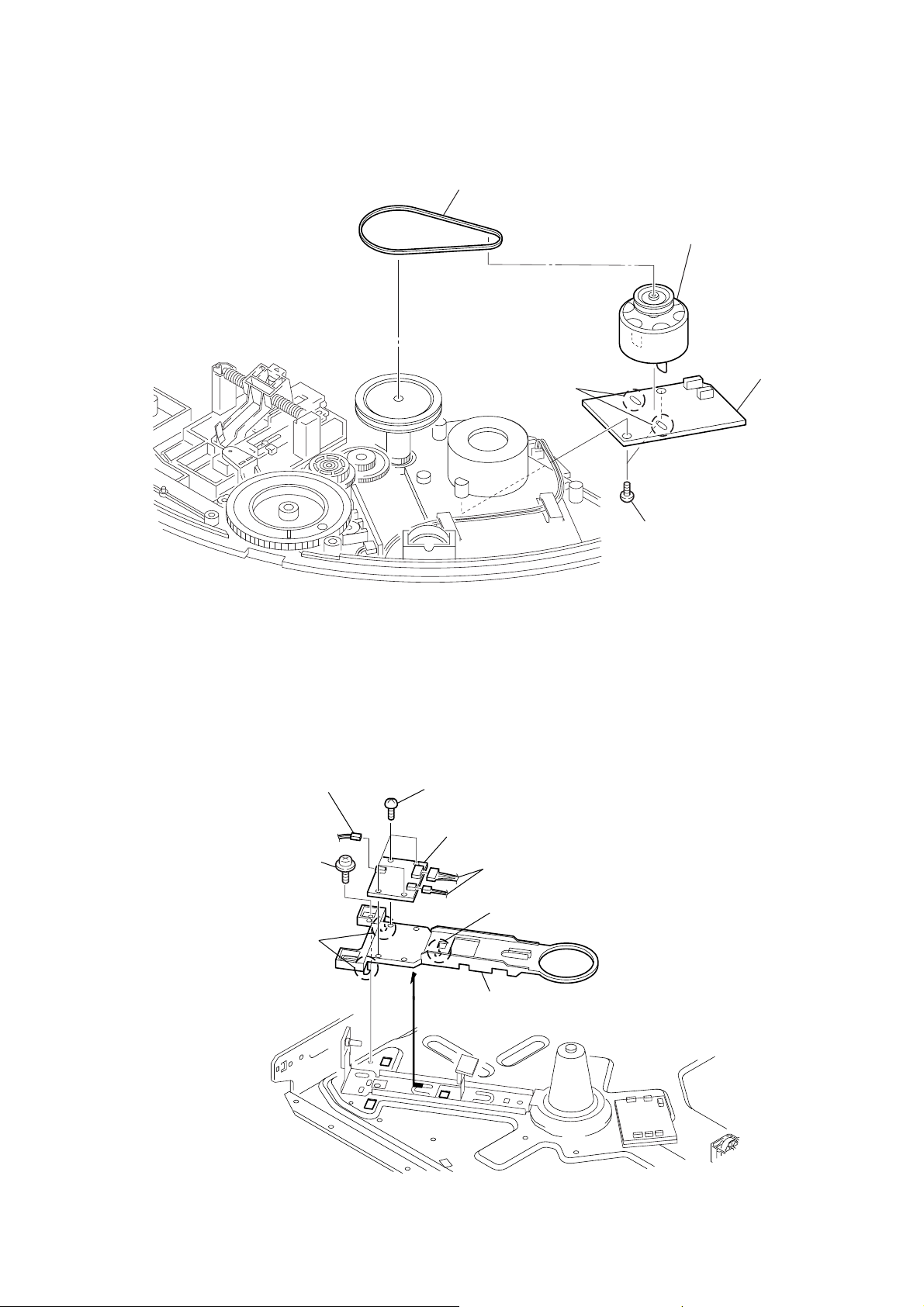
screw (PTPWH 3 × 6)
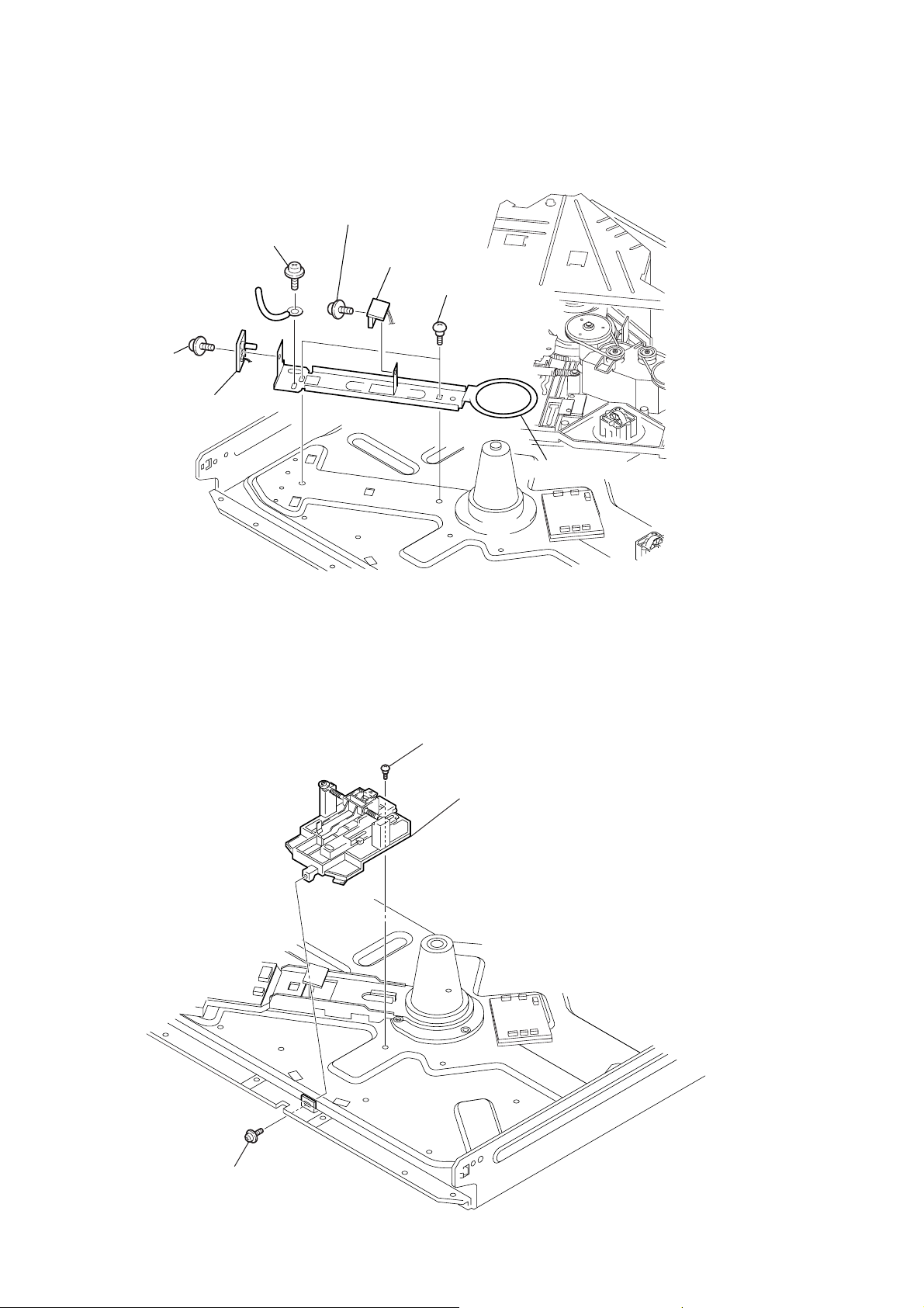
3-16. DOOR SW BOARD
1
screw (PTPWH 2.6 × 8)
2
gear (cam)
3
screw (PTPWH 2.6 × 8)
4
gear (B)
5
two screws
(BVTP 2.6
6
door SW board
DVP-CX777ES
×
8)
Precaution during the gear (cam) installation
1
Move the slider (pop-up) and the lever (pu joint) fully
in the direction of the arrow
slider (pop-up)
The levers of the two rotary switches on the door SW board
are shown in the illustration below.
A
A
.
lever (pu joint)
two rotary switches
door SW board
2
Install the gear (cam) in the direction shown
in the illustration and rotate it fully
in the direction of the arrow
3
When the gear (cam) happens to go too deep,
return it to the original position
in the direction of the arrow
B
.
gear (cam)
C
.
B
C
19
DVP-CX777ES
)
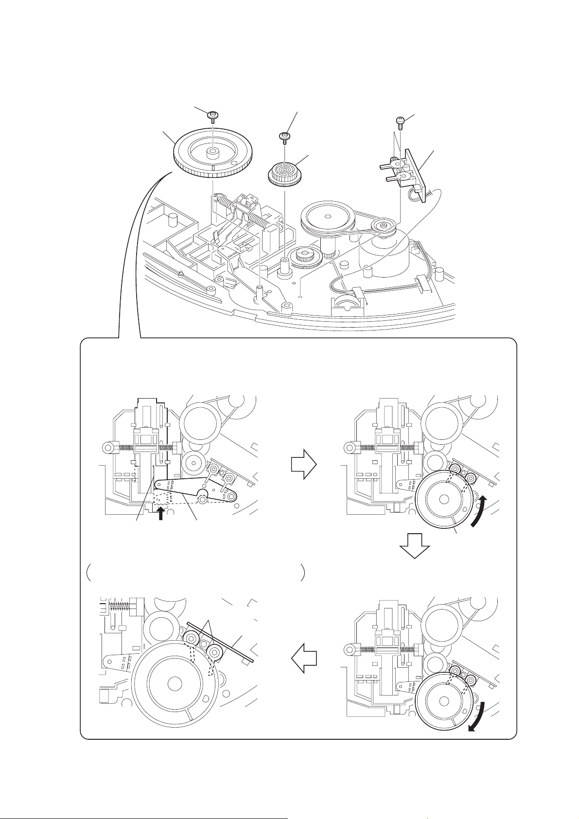
3-17. LOCK SW BOARD, LOADING SW BOARD
2
screw
(BVTP3
×
8)
A
B
1
Rotate the pulley (400) in the
direction of the arrow A fully.
3
Rotate the pulley (400) in the
direction of the arrow B fully.
Note for installation
When installing the
loading SW board and
lock SW boards,
align the leads position as shown.
loading SW board
lock SW board
leads
position
claws
9
lock SW
board
8
screw
(BVTP 3 × 8)
7
gear (center)
5
tapping screw
4
6
pulley (400
0
screw
(BVTP 2.6 × 8)
qa
loading SW
board
belt
20
3-18. CD/DVD MECHANISM DECK BLOCK
(CDM62-DVBU26)
6
CD/DVD mechanism deck block (CDM62-DVBU26)
5
seven screws
(BVTP 3 × 8)
DVP-CX777ES
1
connector
(CN905)
2
connector
(CN903)
3
screw (PSW 3 × 8)
4
four screws
(BVTP 3 × 8)
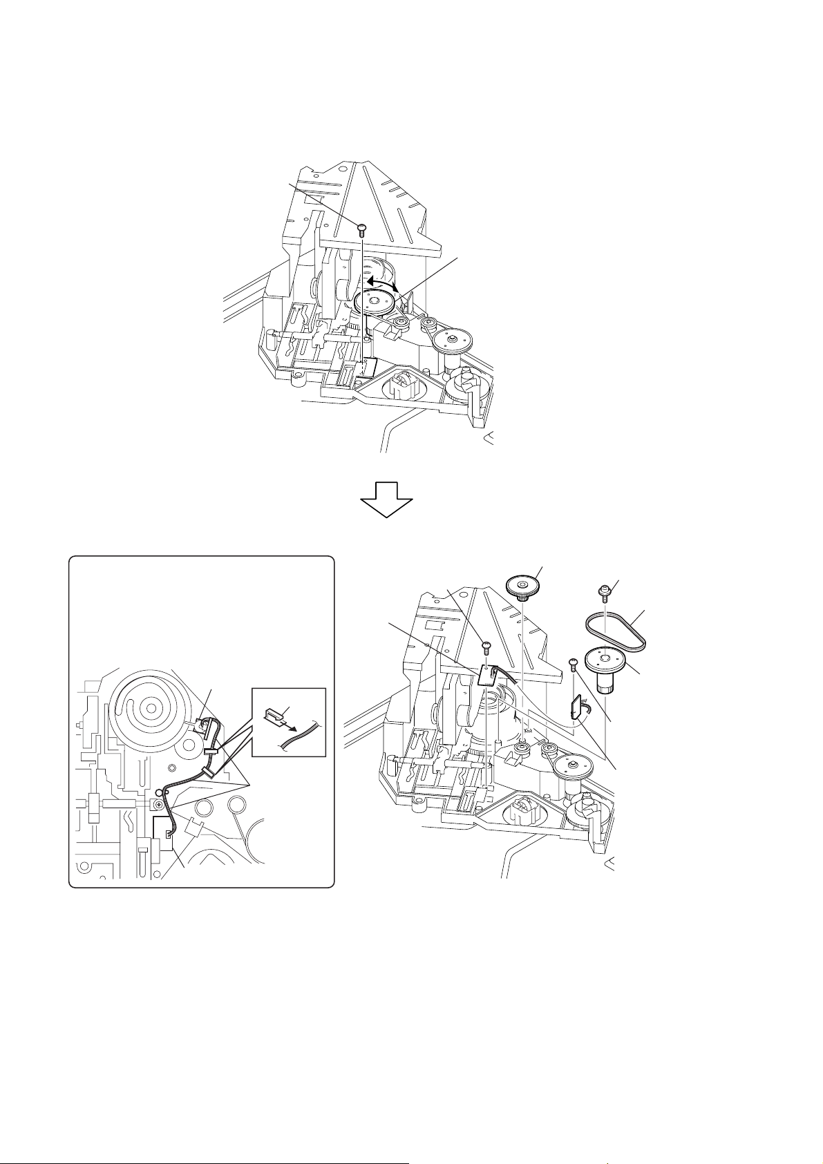
3-19. MOTOR (400) ASSY (LOADING) (M602)/(TABLE) (M601), LOADING MOTOR BOARD
1
two belts (400)
4
motor (400) assy (loading)
(M602)
6
motor (400) assy (table)
(M601)
2
three screws
(PTPWH 2.6
3
Remove two
solders.
7
loading motor
board
5
Remove two
solders.
×
8)
21
DVP-CX777ES
3-20. OPTICAL PICK-UP
(KHM-290AAA)
3
step screw (M)
7
insulator
8
optical pick-up (KHM-290AAA)
1
step screw (M)
5
2
step screw (M)
6
insulator
insulator
4
holder (BU) block
22

SECTION 4
TEST MODE
DVP-CX777ES
4-1. GENERAL DESCRIPTION
The T est Mode allo ws you to mak e diagnosis and adjustment easily using the remote commander and monitor TV. The instructions,
diagnostic results, etc. are given on the on-screen display (OSD).
4-2. STARTING TEST MODE
Press the [TOP MENU], [CLEAR], I/1 keys on the remote commander in this order with the power of main unit in OFF status,
and the Test Mode starts, then “DIAG START” will be displayed
on the fluorescent display tube and the menu shown below will be
displayed on the TV screen. At the bottom of menu screen, the
model name and revision number are displayed. Last Off at the
lower right of screen indicates the information code concerning
the last power off. To execute each function, select the desired
menu and press its number on the remote commander. To exit from
the Test Mode, press the I/1 key.
Test Mode Menu
0. Syscon Diagnosis
1. Drive Auto Adjustment
2. Drive Manual Operation
3. Mecha Aging
4. Emergency History
5. Version Information
6. Video Level Adjustment
Exit: POWER Key
Model :TTX-15xxxx
Revision:x.xxx Last Off: xx
Power Off Information Code List
00: Primary Power Off
01: Power Off Request from SYSTEM CONTROL
02: Power Off by Emergency Power Off Command from SYS-
TEM CONTROL
(if information is sent from SYSTEM CONTROL)
03: IF CON Judged that SYSTEM CONTROL is Faulty
04: Power Off from Diagnosis Mode of IF CON
05: Forced Power Off by the User
06: Power Off by Power Supply Voltage Monitor
4-3. SYSCON DIAGNOSIS
The same contents as board detail check by serial interface can be
checked from the remote commander. On the Test Mode Menu
screen, press [0] key on the remote commander, and the follo wing
check menu will be displayed.
### Syscon Diagnosis ###
Check Menu
0 . Quit
1 . All
2 . Version
3 . Peripheral
4 . Servo
5 . Supply
6 . AV Decoder
7 . Video
8 . Audio
_
0. (Quit)
Quit the Syscon Diagnosis and return to the Test Mode Menu.
1. (All items continuous check)
This menu checks all diagnostic items continuously. Normally, all
items are checked successively one after another automatically
unless an error is found, but at a certain item that requires judgment through a visual check to the result, the following screen is
displayed for the key entry.
### Syscon Diagnosis ###
Diag All Check
No. 2 Version
2-3. ROM Check Sum
Check Sum = xxxx
Press NEXT Key to Continue
Press PREV key to Repeat
For the ROM Check, the check sum calculated by the Syscon is
output, and therefore you must compare it with the specified value
for confirmation.
Following the message, press > key to go to the next item,
or . key to repeat the same check again.
23

DVP-CX777ES
To quit the diagnosis and return to the Check Menu screen,
press x or [ENTER] key. If an error occurred, the diagnosis is
suspended and the error code is displayed as shown below.
### Syscon Diagnosis ###
3-2. EEPROM Check
Error 03 : EEPROM Write/Read N
Address : 00000001
Write Data: 2492
Read Data : 2490
Press NEXT Key to Continue
Press PREV key to Repeat
_
Press x key to quit the diagnosis, or . key to repeat the same
item where an error occurred, or > key to continue the check
from the item next to faulty item.
* In “All item continuous check”, pressing stop or enter will not
quit the diagnosis.
Selecting [2] and subsequent items call the submenu screen of
each item. When “———” is displayed in the submenu, it means
that the test is not supported in the model.
For example, if “5. Supply” is selected, the following submenu
will be displayed.
### Syscon Diagnosis ###
Check Menu
No. 5 Supply
0. Quit
1. All
2. ARP Register Check
3. ARP to RAM Data Bus
4. ARP to RAM Address Bus
5. ARP RAM Check
0. (Quit)
Quit the submenu and return to the main menu.
1. (All submenu items continuous check.)
This menu checks 2 and subsequent items successively . At the item
where visual check is required for judgment or an error occurred,
the checking is suspended and the message is output for key entry .
Normally, all items are checked successively one after another
automatically unless an error is found.
Selecting [2] and subsequent items executes respective menus and
outputs the results.
For the contents of each submenu, see “General Description of
Checking Method” and “Check Items List”.
General Description of Checking Method
2. V ersion
(2-2) Revision
ROM revision number is displayed.
Error: Not detected.
The revision number defined in the source file is displayed
with four digits.
(2-3) ROM Check Sum
Check sum is calculated.
Error: Not detected.
8-bit data are added up to the ROM address 0x000F0000 to
0x002EFFFF , and the result is displayed with 4-digit hexadecimal number. Error is not detected. Compare the result
with the specified value.
(2-4) Model Type
Model code is displayed.
Error: Not detected.
The model code read from the EEPROM is displayed with
2-digit hexadecimal number.
(2-5) Region
Region code is displayed.
Error: Not detected.
The region code determined from the model code is displayed.
(2-6) M’t Check
Mount resistance is checked.
Error 22: The region code does not accord.
Check whether the region code that is deduced from model
resistance and destination resistance accords with the region code that is deduced from region resistance value.
3. Peripheral
(3-2) EEPROM Check
Data write t read, and accord check
Error 03: EEPROM write/read discord
0x9249, 0x2942 and 0x4294 are written to the address 0x00
to 0xFF of the EEPROM and then read for checking. Before writing, the data are saved, then after checking, they
are written to restore the contents of EEPROM.
(3-3) Gate Array Check
Data write → read, and accord check
Error 02: Gate Array write/read discord
Data of 0x00 to 0xFF is written sequentialy to the address
0xF and then read for checking.
(3-4) NAND FLASH Check
Data delete → write → read, and accord check
Error 04: delete error
Error 05: write error
Error 06: read data discord
Error 21: more than ten blocks are defective
Deleting, writing and checking read data are executed to
the zeroth block of Flash memory.
If any detective block is found, the address is displayed.
When more than ten blocks are defective, it is considered
as an error.
24
(3-5) SACD Check
Device reset t internal organs RAM check.
Error 50: Write and read data discord.

DVP-CX777ES
(3-6) VENC Check
Data write t read, and accord check
Error 52: Write/read data discord
Error may occur due to defect of access with syscon.
(3-7) —————
Check no support.
(3-8) EX RAM Check
Test Data write t read, and accord check
Error 02: The external RAM used in the system control is
checked.
4. Servo
(4-2) Servo DSP Check
Data write t read, and accord check
Error 12: Read data discord
0x9249, 0x2942 and 0x4294 are written to the RAM address 0x602 of the Servo DSP and then read for checking.
(4-3) —————
Check no support.
(4-4) RF Amp (SSI) W/R Check
Data write t read, and accord check
Error 13: RF Amp register write, and read data discord
Implement 8-bit shift operation of the 0x01 to the readable/writable register of the RF Amp. If once write data do
not accord with read data, it is NG.
5. Data Supply System
(5-2) ARP Register Check
Data write t read, and accord check
Error 08: ARP register write, and read data discord
Data 0x00 to 0xFF is written sequentially to the ARP TMAX
register (address 0xC6) and then read for checking.
(5-3) ARP to RAM Data Bus
Data write t read, and accord check
Error 09: ARP Tt RAM data bus error
Data 0x0001 to 0x8000 where one bit each is set to 1 are
written to the address 0 of RAM (IC303) connected to the
ARP (IC301) through the bus, then they are read and
checked. In case of discord, written bit pattern and read
data are displayed. If data where multiple bits are 1 are
read, the bits concerned may touch each other. Further, if
data where certain bit is always 1 or 0 regardless of written
data, the line could be disconnected or shorted.
(5-4) ARP to RAM Address Bus
Data write t other address read discord check
Error 10: ARP Tt RAM address bus error
Caution: Address and data display in case of an error is
different from the display of other diagnosis (described
later).
Before starting the test, all addresses of RAM (IC303) are
cleared to 0x0000.
First, 0xA55A is written to the address 0x00000, and the
address data are read and checked from addresses 0x00001
to 0x80000 while shifting 1 bit each. Next, the data at that
address is cleared, and it is written to the address 0x00001,
and read and checked in the same manner. This check is
repeated up to the address 0x80000 while shifting the address data by 1 bit each.
If data other than 0 is read at the addresses except written
address, an error is given because all addresses were already cleared to 0. In this check, the error display pattern is
different from that of other diagnosis; read data, written
address, and read address are displayed in this order. Ho wever, the message uses same template, and accordingly exchange Address and Data when reading. The following display, for example,
### Syscon Diagnosis ###
5-4. ARP to RAM Address Bus
Error 10: ARP - RAM Address B
Address : 0000A55A
Write Data : 00000000
Read Data : 00080000
Press NEXT Key to Continue
Press PREV key to Repeat
_
shows the data 0xA55A was read from address 0x00080000
though it was written to the address 0x00000000. This implies that these addresses are in the form of shadow. Also,
if the read data is not 0xA55A, another error will be present.
(5-5) ARP RAM Check
Data write t read, and accord check
Error 11: ARP RAM read data discord
The program code data stored in ROM are copied to all
areas of RAM (IC303) connected to the ARP (IC301)
through the bus, then they are read and checked if they accord. If the detail check was selected initially, the data are
written to all areas and read, then the same test is conducted
once again with the data where all bits are inverted between
1 and 0. If discord is detected, faulty address, written data,
and read data are displayed following the error code 11,
and the test is suspended.
25

DVP-CX777ES
6. AV Decoder
(6-2) 1935 RAM
Data write t read, and accord check
Error 14: AVD RAM read data discord
The program code data stored in ROM (IC106) are copied
to all areas of RAM (IC404, 405) connected to the AVD
(IC403) through the bus, then they are read and checked if
they accord. Further, the same test is conducted once again
with the data where all bits are inverted between 1 and 0. If
discord is detected, faulty address, written data, and read
data are displayed following the error code 14, and the test
is suspended.
During the test, OSD display becomes blank as the OSD
area is also checked.
(6-3) 1935 SP
ROM t AVD RAM t Video OUT
Error: Not detected.
The data including sub picture streams in ROM (IC106)
are transferred to the RAM (IC404, 405) in AVD (IC403),
and output as video signals from the AVD (IC403).
Though OSD display becomes blank, the output of video
signals continues until the key is pressed.
7. Video Output
(7-2) Color Bar
AVD color bar command write t Video OUT
Error: Not detected.
The command is transferred to the AVD, and the color bar
signals are output from video terminals.
(7-3) Composite Out
AVD color bar command write t Video (Composite, Y/C)
OUT
Error: Not detected.
The command is transferred to the AVD, and the color bar
signals are output from video terminals.
(7-4) Y/C Out
AVD color bar command write → Video (Composite, Y/C)
OUT
Error: Not detected.
The command is transferred to the AVD, and the color bar
signals are output from video terminals.
They are output from all video terminals (Composite, Y/C,
Component).
(7-5) —————
Check no support.
(7-6) Component Out
AVD color bar command write t Video (Component, Y/
C) OUT
Error: Not detected.
The command is transferred to the AVD, and the color bar
signals are output from video terminals.
(7-7) —————
Check no support.
8. Audio Output
(8-2) ARP t 1935
Data flow from supply system DRAM to SDRAM of AV
Decoder is tested.
Error 15: ARP t 1935 video NG
16: ARP t 1935 audio NG
(8-3) Audy
Register check of Audy (IC801) and SDRAM (IC802) check
are performed. After above checks are performed, transit
to the next test tone (8-4).
(8-4) Test Tone
Pink noise output
Error: Not detected.
In the models without DD output, the test tone is output
from L and R of 2-channel only, and in the models with
DD output, the test tone is output from L and R of 2-channel, and all channels of 5.1 output.
After turning on all outputs, each time the > key is
pressed, the output channel is switched for individual channel checking.
Diagnosis Check Items List
2. V ersion Display
(2-2) Revision
(2-3) ROM Check Sum
(2-4) Model Type
(2-5) Region
(2-6) M’t Check
3. Peripheral
(3-2) EEPROM Check
(3-3) Gate Array Check
(3-4) NAND FLASH Check
(3-5) SACD Check
(3-6) VENC Check
(3-7) ———— (Function not supported)
(3-8) EX RAM Check
4. Servo
(4-2) Servo DSP Check
(4-3) ———— (Function not supported)
(4-4) RF Amp (SSI) W/R Check
5. Data Supply System
(5-2) ARP Register Check
(5-3) ARP to RAM Data Bus
(5-4) ARP to RAM Address Bus
(5-5) ARP RAM Check
6. AV Decoder
(6-2) 1935 RAM
(6-3) 1935 SP
7. Video Output
(7-2) Color Bar
(7-3) Composite Out
(7-4) Y/C Out
(7-5) ———— (Function not supported)
(7-6) Component Out
(7-7) ———— (Function not supported)
26
8. Audio Output
(8-2) ARP t 1935
(8-3) Audy
(8-4) Test Tone

DVP-CX777ES
Error Codes List
00: Error not detected
01: RAM write/read data discord
03: EEPROM NG
04: Flash memory clear error
05: Flash memory write error
06: Flash memory read data discord
08: ARP register read data discord
09: ARP Tt RAM data bus error
10: ARP Tt RAM address bus error
11: ARP RAM read data discord
12: Servo DSP NG
13: RF Amp NG
14: 1935 SDRAM NG
15: ARP t 1935 video NG
16: ARP t 1935 audio NG
1A:System call error (Function not supported)
1B:System call error (Parameter error)
1C:System call error (Illegal ID number)
20: System call error (Time out)
22: Resistor installation error
50: SACD Decoder W/R NG
52: Video Encoder W/R NG
55: External RAM W/R NG
90: Error occurred
91: User verification NG
92: Diagnosis cancelled
4-4. DRIVE AUTO ADJUSTMENT
DVD reference disc
Single Layer
HLX-503 (J-6090-069-A) (NTSC) OR
HLX-504 (J-6090-088-A) (NTSC)
Dual Layer
HLX-501 (J-6090-071-A) (NTSC) OR
HLX-505 (J-6090-089-A) (NTSC)
CD reference disc
YEDS-18 (3-702-101-01) OR
PATD-012 (4-225-203-01)
On the T est Mode Menu screen, press [1] key on the remote commander, and the drive auto adjustment menu will be displayed.
## Drive Auto Adjustment ##
Adjustment Menu
0. ALL
1. DVD-SL
2. CD
3. DVD-DL
4. LCD
_
Exit: RETURN
Normally, [0] is selected to adjust DVD (single layer), CD, and
DVD (dual layer) in this order. But, individual items can be adjusted for the case where adjustment is suspended due to an error.
In this mode, the adjustment can be made easily through the operation following the message displayed on the screen. Which disc
is currently adjusted is displayed on the fluorescent display tube.
0. ALL
You will be asked if EEPROM data are initialized or not, and for
this prompt, select
setting data in EEPROM, Emergency History and Hour Meter ar e
cleared to initialize. Then, [1] DVD-SL disc, [2] CD disc, and [3]
DVD-DL disc are adjusted in this order . Because the changer model
can accept multiple discs in advance of adjustment, adjustments
can be continued by exchanging discs automatically whenever an
adjustment is completed following the instruction on screen. You
can exit the adjustment by pressing the x button. In adjusting
each disc, the mirror time is measured to check the disk type. In
the auto adjustment, whether the disc type is correct is not checked
unlike conventional models, and accordingly, take care not to insert a different type of disc.
Three kinds of discs can be set in advance. In this case, set discs in
order to the displayed number with following the massage. Every
time after adjusting a disc, the disc is replaced and adjustment is
continued automatically.
[0] and press the [ENTER] key. First, the servo
Set Disc
Disc slot number 1: DVD-SL
Disc slot number 2: CD
Disc slot number 3: DVD-DL
27

DVP-CX777ES
1. DVD Single Layer Disc
Select [1], insert DVD single layer disc, and press [ENTER] key,
and the adjustment will be made through the following steps, then
adjusted values will be written to the EEPR OM. The disc slot No.
1 is used in the changer type model. If there is no disc on the disc
slot No. 1, the tray will be open to wait for closing. If there is a
disc on the table, the adjustment starts immediately. If y ou put a
disc prior to adjustment, confirm that the SL disc is set on the disc
slot 1.
DVD Single Layer Disc Adjustment Steps
1. Sled Reset
2. Disc Check Memory SL
3. Set Disc Type SL
4. Spindle Start
5. Laser Diode ON
6. Focus Error Check
7. Focus ON 0 with PI Level measure
8. Auto Track Offset Adjust L0
9. Try Level Check
10. Tracking ON
11. CLVA ON
12. Sled ON
13. Auto Focus Balance Adjust
14. Auto Loop F ilter Offset Adjust
15. Auto Focus Gain Adjust L0
16. Auto Focus Balance Adjust L0
17. EQ Boost Adjust
18. Auto Loop F ilter Offset Adjust
19. Auto Track Gain Adjust
20. RF Level Measure
21. Jitter measure
22. Ee p Copy Loop Filter Offset
23. All Servo Off
2. CD Disc
[2], insert CD disc, and press [ENTER] key, and the adjust-
Select
ment will be made through the following steps, then adjusted values will be written to the EEPROM. The disc slot No. 2 is used in
the changer type model. If there is no disc on the disc slot No. 2,
the tray will be open to wait for closing. If there is a disc on the
table, the adjustment starts immediately. If you put a disc prior to
adjustment, confirm that the CD is set on the disc slot 2.
CD Adjustment Steps
1. Sled Reset
2. Disc Check Memory CD
3. Set Disc Type CD
4. Spindle Start
5. Laser Diode ON
6. Focus Error Check
7. Focus ON 0 with PI Level measure
8. Auto Track Offset Adjust L0
9. Try Level Check
10. Tracking ON
11. CLVA ON
12. Sled ON
13. Auto Focus Balance Adjust
14. Auto Loop F ilter Offset Adjust
15. Auto Focus Gain Adjust L0
16. Auto Focus Balance Adjust L0
17. EQ Boost Adjust
18. Auto Loop F ilter Offset Adjust
19. Auto Track Gain Adjust
20. Copy Adjustment Data to LCD
21. RF Level Measure
22. Jitter measure
23. All Servo Off
3. DVD Dual Layer Disc
Select
[3], insert DVD dual layer disc, and press [ENTER] key,
and the adjustment will be made through the following steps, then
adjusted values will be written to the EEPR OM. The disc slot No.
3 is used in the changer type model. If there is no disc on the disc
slot No. 3, the tray will be open to wait for closing. If there is a
disc on the table, the adjustment starts immediately. If you put a
disc prior to adjustment, confirm that the DL disc is set on the disc
slot 3.
DVD Dual Layer Disc Adjustment Steps
1. Sled Reset
2. Disc Check Memory DL
3. Set Disc Type DL
DVD DL Layer 1 Adjust
4. Spindle Start
5. Laser Diode ON
6. Focus ON 0 with PI Level measure
7. Auto Track Offset Adjust L1
8. Tracking ON
9. ClVA ON
10. Sled ON
11. Auto Focus Balance Adjust
12. Auto Loop Filter Offset Adjust
13. Auto Focus Gain Adjust L1
14. EQ Boost Adjust L1
15. Auto Track Gain Adjust L1
16. Jitter measure
DVD DL Layer 0 Adjust
17. Focus Jump (L1 t L0)
18. Auto Track Offset Adjust L0
19. Tracking ON
20. ClVA ON
21. Sled ON
22. Auto Focus Balance Adjust
23. Auto Focus Gain Adjust L0
24. Auto Focus Balance Adjust L0
25. EQ Boost Adjust L0
26. Auto Track Gain Adjust L0
27. Jitter measure
28. All Servo Stop
4. LCD
LCD disc is not adjusted because the adjusted data of CD are reflected, and SACD (hybrid disc) is not adjusted because the adjusted data of CD and DVD-DL are reflected.
28
DVP-CX777ES
4-5. DRIVE MANUAL OPERATION
On the T est Mode Menu screen, select [2], and the manual oper ation menu will be displayed. For the manual operation, each servo
on/off control and adjustment can be executed manually.
## Drive Manual Operation ##
1. Disc type
2. Servo Control
3. Track/Layer Jump
4. Manual Adjustment
5. Auto Adjustment
6. Memory Check
7. Changer Manual Move
8. Changer Mecha Check
0. Disc Check Memory
_
Operation Menu
Exit: RETURN
In using the Manual Operation menu, take care of the following
points. These commands do not provide protection, thus requiring
correct operation. The sector address or time code field is displayed when a disc is loaded.
1. Set correctly the disc type to be used on the Disc Type
setting screen.
The Disc T ype setting must be performed after a disc wa s
loaded.
The set Disc Type is cleared when the tray is opened.
2. After power ON, if the Manual Operation was selected,
first perform “Reset SLED TIL T” by opening 1. Disc Type
screen.
3. In case of an alarm, immediately press the x button to
stop the servo operation, and turn the power OFF.
Basic operation (controllable from front panel or remote commander)
I/1 :Power OFF
x : Servo stop
A (DISC EJECT) : Stop+Eject/Loading
O (RETURN) : Return to Operation Menu or Test Mode
Menu
> , . :Transition between sub modes of menu
[1] to [9], [0] : Selection of menu and items
Cursor [Q]/[q] : Increase/Decrease in manually adjusted value
0. Disc Check Memory
Disc Check
1. SL Disc Check
2. CD Disc Check
3. DL Disc Check
0. Reset SLED TILT
_
On this screen, the mirror time is measured and written to the
EEPROM to check the disc type. First, set a DVD SL disc and
press [1], then set a CD disc and press [2], and finally set a DVD
DL disc and press [3]. The measured mirror time is displayed respectively.
The adjustment must be executed more than once after default
data were written.
From this screen, you can go to another mode by
pressing > or . key, but you cannot enter this mode from
another mode. You can enter this mode from the Operation Menu
screen only.
1. Disc Type
Disc Type
1. Disc Type Auto Check
2. DVD SL 12cm
3. DVD DL 12cm
4. CD 12cm
5. LCD 12cm
6. DVD SL 8cm
7. DVD DL 8cm
8. CD 8cm
9. LCD 8cm
0. Reset SLED TILT
_ EMG. 00
0. Reset SLED TIL
On this screen, select the disc type. To select the disc type, press
the number of the loaded disc. The selected disc type is displayed
at the bottom. Selecting [1] automatically selects and displays the
disc type. In case of wrong display, retry “Disc Check Memory”.
Also, opening the tray causes the set disc type to be cleared. In
this case, set the disc type again after loading.
In performing manual operation, the disc type must be set.
29

DVP-CX777ES
Once the disc type has been selected, the sector address or time
code display field will appear as shown below. T hese values are
displayed when PLL is locked.
Disc Type
1. Disc Type Auto Check
2. DVD SL 12cm
3. DVD DL 12cm
4. CD 12cm
5. LCD 12cm
6. DVD SL 8cm
7. DVD DL 8cm
8. CD 8cm
9. LCD 8cm
0. Reset SLED TILT
_ SA.------ SI.-- EMG.00
DVD SL 12cm Jitter FF
Display when DVD SL 12cm disc was selected
Disc Type
1. Disc Type Auto Check
2. DVD SL 12cm
3. DVD DL 12cm
4. CD 12cm
5. LCD 12cm
6. DVD SL 8cm
7. DVD DL 8cm
8. CD 8cm
9. LCD 8cm
0. Reset SLED TILT
_ TC.--:--:-- EMG.00
CD 12cm Jitter FF
Display when CD 12cm disc was selected
[0] Reset SLED TILT : Reset the Sled and Tilt to initial position.
(Reset the Sled only to initial position because the Tilt mechanism is not available
in this model.)
[1] Disc Type Check : Judge automatically the loaded disc. As
the judged result is displayed at the bottom of screen, make sure that it is correct.
If Disc Check Memory menu has not been
executed after EEPROM default setting,
the disc type cannot be judged. In this case,
return to the initial menu and make a check
for three types of discs (SL, DL, CD).
[2] to [9] : Select the loaded disc. The adjusted value
is written to the address of selected disc.
No further entry is necessary if [1] was
selected.
2. Servo Control
Servo Control
1. LD Off R. Sled FWD
2. SP Off L. Sled REV
3. Focus Off
4. TRK. Off
5. Sled Off
6. CLVA Off
7. FCS. Srch Off
0. Reset SLED TILT
_ SA.------ SI.-- EMG.00
DVD SL 12cm Jitter FF
On this screen, the servo on/off control necessary for replay is
executed. Normally, turn on each servo from 1 sequentially and
when CLVA is turned on, the usual tr ace mode becomes activ e . In
the trace mode, DVD sector address or CD time code is displayed.
This is not displayed where the spindle is not locked.
The spindle could run overriding the control if the spindle system
is faulty or RF is not present. In such a case, do not operate CL VA.
[0] Reset SLED TILT : Reset the Sled and Tilt to initial position.
(Reset the Sled only to initial position because the Tilt mechanism is not available
in this model.)
[1] LD : Turn ON/OFF the laser.
[2] SP : Turn ON/OFF the spindle.
[3] Focus : Search the focus and turn on the focus.
[4] TRK. : Turn ON/OFF the tracking servo.
[5] Sled : Turn ON/OFF the sled servo. When PLL
is not locked (cannot be locked), the sled
servo is not turned ON. The display keeps
OFF.)
[6] CLVA :Turn ON/OFF normal servo of spindle
servo.
[7] FCS. Srch : Apply same voltage as that of focus search
to the focus drive to check the focus driv e
system.
5 Sled FWD : Move the sled outward. Perform this op-
eration with the tracking servo turned off.
% Sled REV : Move the sled inward. Perform this opera-
tion with the tracking servo turned off.
30
 Loading...