

Sony DVP-C660, DVP-C670D, DVP-C675D Service Manual
DVP-C660
/
C670D/C675D
RMT-D119A/D121A/D121O
SERVICE MANUAL
Photo: DVP-C670D
SPECIFICATIONS
CD/DVD player
Laser Semiconductor laser
Signal format system
Audio characteristics
Frequency response
Signal-to-noise ratio
Harmonic distortion
Dynamic range
Wow and flutter
NTSC (C660/C670D: US, Canadian/C675D)
NTSC/PAL (C670D: Australian, E)
DVD (PCM 96 kHz): 2 Hz to 44 kHz
(±1 dB)* (C660)
DVD (PCM 96 kHz): 2 Hz to 44 kHz
(±1.0 dB) (C670D: Australian, E)
DVD (PCM 96 kHz): 2 Hz to 44 kHz
(±0.5 dB) (C670D: US, Canadian/C675D)
DVD (PCM 48 kHz): 2 Hz to 22 kHz
(±0.5 dB)
CD: 2 Hz to 20 kHz (±0.5 dB)
More than 110 dB
(AUDIO OUT connectors only)
(C660/C670D: Australian, E)
More than 115 dB
(AUDIO OUT connectors only)
(C670D: US, Canadian/C675D)
Less than 0.0025%
(C670D: US, Canadian/C675D)
Less than 0.003%
(C660/C670D: Australian, E)
More than 100 dB (DVD)
More than 97 dB (CD)
(C660D/C670D: Australian, E)
More than 98 dB (CD)
(C670D: US, Canadian/C675D)
Less than detected value
(±0.001% W PEAK)
Outputs/Inputs
Jack
type
/B-Y,
Phono
jacks
Optical
output
connector
Phono
jack
Phono
jacks
4-pin
mini DIN
Phono
jacks
Phono
jack
Mini jack
Phone
jack
Mini jack
Phono
jack
120 V AC, 60 Hz
(C660/C670D: US, Canadian)
AUDIO OUT
(1, 2)
DIGITAL OUT
(OPTICAL)
DIGITAL OUT
(COAXIAL)
VIDEO OUT
(1, 2)
S VIDEO OUT
(1, 2)
COMPONENT
VIDEO OUT
B
(Y, P
P
R
/R-Y)
5.1CH
OUTPUT
(C670D/C675D)
S-LINK
(C670D: US, Canadian/C675D)
PHONES
(C670D/C675D)
MEGA
CONTROL
AUDIO IN
General
Power requirements
Output/input
level
2 Vrms
(at 50 kilohms)
–18 dBm
0.5 Vp-p
1.0 Vp-p
Y: 1.0 Vp-p
C: 0.286 Vp-p
Y: 1.0 Vp-p
P
B
/B-Y,
R
/R-Y:
P
0.7 Vp-p
2 Vrms
(at 50 kilohms)
–
12 mW
–
2 Vrms
Load impedance
Over 10 kilohms
Wave length: 660 nm
75 ohms terminated
75 ohms,
sync negative
75 ohms,
sync negative
75 ohms terminated
75 ohms,
sync negative
75 ohms
Over 10 kilohms
–
32 ohms
–
47 kilohms
US Model
Canadian Model
DVP-C660/C670D
E Model
Australian Model
DVP-C670D
PX Model
DVP-C675D
220 V – 240 V AC, 50/60 Hz
(C670D: Australian)
Power consumption
Dimensions (approx.)
Mass (approx.)
Operating temperature
Operating humidity
Supplied accessories
• Audio/video connecting cord (1)
(C660/C670D: Australian, E)
• Audio/video/S-link connecting cord (1)
(C670D: US,Canadian/C675D)
• S video cord (1)
• Remote commander (remote) (1)
• Size AA (R6) batteries (2)
• Plug adaptor (1) (C670D: E/C675D)
* The signals from AUDIO OUT connectors are measured. When you
play PCM sound tracks with a 96 kHz sampling frequency, the
output signals from the DIGITAL OUT (OPTICAL, COAXIAL) are
converted to 48 kHz (sampling frequency).
Design and specifications are subject to change without notice.
110 – 240 V AC, 50/60 Hz (C670D: E/C675D)
14 W (C660)
17 W (C670D: US, Canadian)
18 W (C670D: Australian, E/C675D)
430 × 95 × 410 mm
3
(17 × 3
/4 × 16 1/4 in.) (w/h/d)
incl. projecting parts (C660)
430 × 95 × 414 mm (17 × 3
(w/h/d) incl. projecting parts
(C670D/C675D)
5.3 kg (12 lb 2 oz) (C660)
5.4 kg (11 lb 14 oz) (C670D/C675D)
5 ˚C to 35 ˚C (41 ˚F to 95 ˚F)
25 % to 80 %
3
/4 × 16 3/8 in.)
CD/DVD PLAYER
Settings and
Adjustments
This chapter describes how to set and
adjust the player using the on-screen
setup menu. Most settings and
adjustments are required to be set
when you first use the player.
This chapter also describes how to set
the remote for controlling the TV or
the AV receiver (amplifier) or the CD
changer.
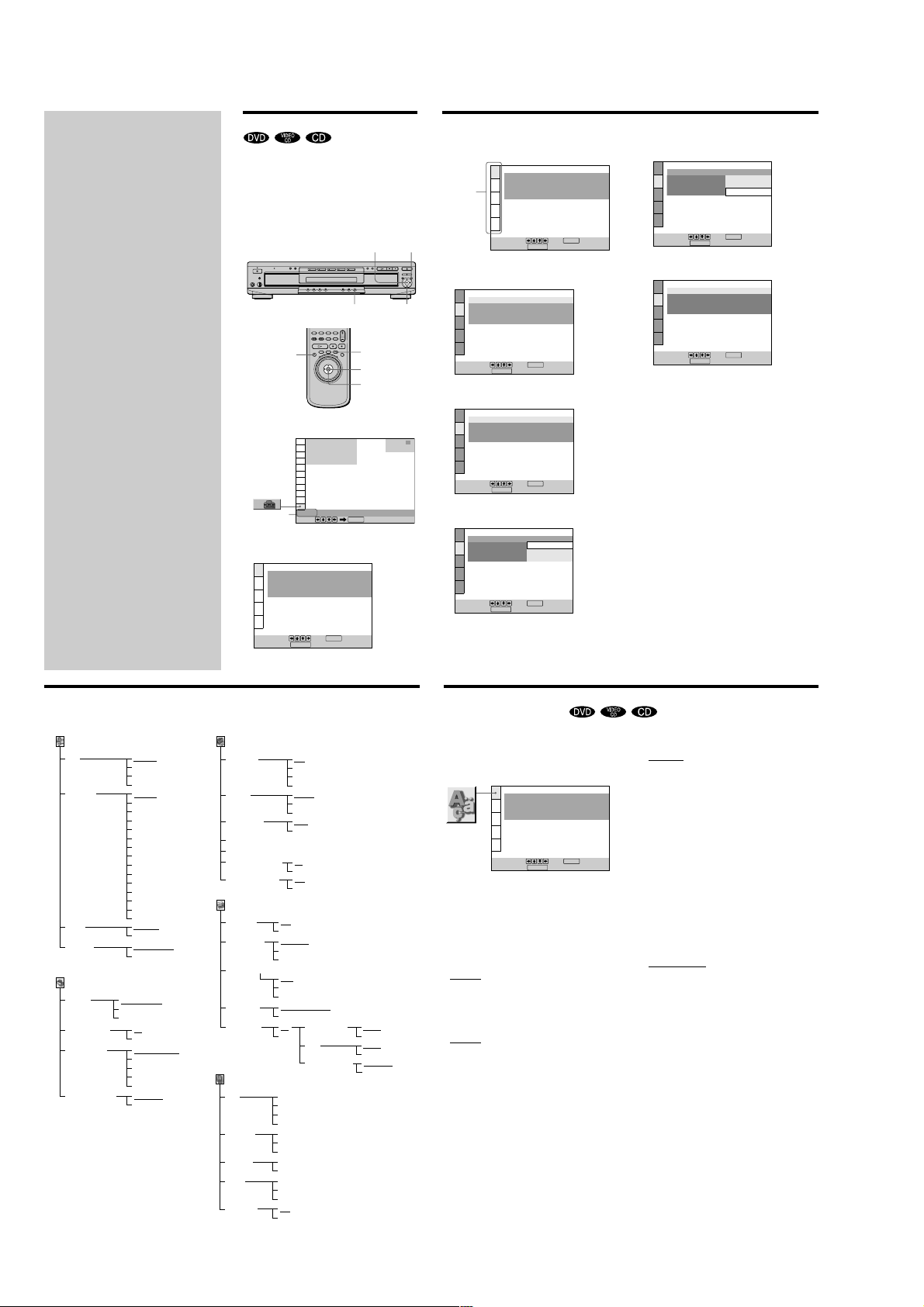
Using the Setup Display
Using the setup display, you can do the initial setup,
adjust the picture and sound and set the various outputs.
You can also set a language for the subtitles and the setup
display, limit playback by children, and so on.
For details on each setup display item, see pages 59 to 69.
Note
You can display the setup display only when the player is in stop
mode.
ORETURN
ENTER
DISPLAY
</M/m/,
3
Select the main item you want using M/m.
LANGUAGE SETUP
OSD:
DVD MENU:
Main item
4
Press ENTER.
The selected main item is highlighted.
AUDIO:
SUBTITLE:
To set, press , then .
DISPLAY
To quit, press .
SCREEN SETUP
TV TYPE:
SCREEN SAVER:
BACKGROUND:
STARTUP SCREEN: STANDARD
4:3 LETTER BOX
JACKET PICTURE
ENGLISH
ENGLISH
ORIGINAL
AUDIO FOLLOW
ENTER
ON
7
Select the setting you want using </M/m/,.
SCREEN SETUP
TV TYPE:
SCREEN SAVER:
BACKGROUND:
STARTUP SCREEN:
To set, press , then .
To quit, press .
8
Press ENTER.
SCREEN SETUP
TV TYPE:
SCREEN SAVER:
BACKGROUND:
STARTUP SCREEN: STANDARD
DISPLAY
4:3 LETTER BOX
4:3 LETTER BOX
4:3 PAN SCAN
16:9/4:3 WIDE MODE
ENTER
16:9/4:3 WIDE MODE
ON
JACKET PICTURE
56
Setup Display Item List
The default settings are underlined.
LANGUAGE SETUP (page 59)
OSD
DVD MENU
AUDIO
SUBTITLE
SCREEN SETUP (page 60)
TV TYPE
SCREEN SAVER
BACKGROUND JACKET PICTURE
STARTUP SCREEN STANDARD
58
ENGLISH
FRENCH
SPANISH
PORTUGUESE
ENGLISH
FRENCH
SPANISH
PORTUGUESE
GERMAN
ITALIAN
DUTCH
CHINESE
JAPANESE
DANISH
SWEDISH
FINNISH
NORWEGIAN
RUSSIAN
OTHERS ,
ORIGINAL
(same as DVD MENU)
AUDIO FOLLOW
(same as DVD MENU)
4:3 LETTER BOX
4:3 PAN SCAN
16:9/4:3 WIDE MODE
ON
OFF
PICTURE MEMORY
GRAPHICS
BLUE
BLACK
PICTURE MEMORY
DISPLAY
1
Press DISPLAY and select “SETUP” using M/m.
1
)
1 2 ( 1
1 8 ( 3 4
C
0 0 : 0 0 : 0 0
SETUP
Selected
Select:
item
2
Press ENTER.
The setup display appears.
LANGUAGE SETUP
OSD:
DVD MENU:
AUDIO:
SUBTITLE:
To set, press , then .
To quit, press .
CUSTOM SETUP (page 61)
AUTO PLAY OFF
DIMMER
PAUSE MODE AUTO
BOOKMARK RESET ,
PARENTAL CONTROL ,
PLAYBACK MEMORY ON
TRACK SELECTION OFF
AUDIO SETUP (page 65)
AUDIO ATT OFF
AUDIO DRC
CENTER SPEAKER EQ
DOWNMIX DOLBY
DIGITAL OUT ON
SPEAKER SETUP (page 67)
SIZE FRONT
DISTANCE FRONT
BALANCE
LEVEL CENTER
TEST TONE
ON
STANDARD
TV MODE
WIDE RANGE
FLAT
ENHANCED
SOFT
NORMAL
OFF
CENTER
REAR(REAR/SIDE)
SUBWOOFER
CENTER
REAR
FRONT
REAR
REAR
SUBWOOFER
OFF
ON
DISPLAY
TIMER
DEMO1
DEMO2
BRIGHT
DARK
OFF
FRAME
OFF
AUTO
SURROUND
DOLBY DIGITAL
DTS
48kHz/96kHz PCM
AUDIO FOLLOW
ENTER
)
ENTER
ENGLISH
ENGLISH
ORIGINAL
ORETURN
ENTER
</M/m/,
STOP
DVD
DVD
D-PCM
DOLBY DIGITAL
D-PCM
DTS
48kHz/16bit
96kHz/24bit
To set, press , then .
DISPLAY
DISPLAY
DISPLAY
DISPLAY
ENTER
4:3 LETTER BOX
JACKET PICTURE
ENTER
4:3 LETTER BOX
4:3 LETTER BOX
4:3 PAN SCAN
16:9/4:3 WIDE MODE
ENTER
To set, press , then .
To quit, press .
5
Select the item you want using M/m.
SCREEN SETUP
TV TYPE:
SCREEN SAVER:
BACKGROUND:
STARTUP SCREEN: STANDARD
To set, press , then .
To quit, press .
6
Press ENTER.
SCREEN SETUP
TV TYPE:
SCREEN SAVER:
BACKGROUND:
STARTUP SCREEN:
To set, press , then .
To quit, press .
ON
To quit, press .
9
Press DISPLAY.
The setup display disappears.
10
Press DISPLAY repeatedly to turn off the on-screen
menu.
To return to the previous screen
Press ORETURN.
To quit while making a selection
Press DISPLAY.
Note
Some setup display items require operations other than selecting
the setting. For details on these items, see the relevant pages.
Setting the Display Language or Sound Track
(LANGUAGE SETUP)
“LANGUAGE SETUP” allows you to set various
languages for the on-screen display or sound track.
The default settings are underlined.
Select “LANGUAGE SETUP” in the setup display.
LANGUAGE SETUP
OSD:
DVD MENU:
AUDIO:
SUBTITLE:
To set, press , then .
DISPLAY
To quit, press .
Notes
• When you select a language that is not recorded on the DVD,
one of the recorded languages is automatically selected for the
“DVD MENU,” “AUDIO” and “SUBTITLE” settings.
• Depending on the DVD, the player may not start playing with
the selected language even when you select a language in
“DVD MENU,” “AUDIO” or “SUBTITLE.”
x OSD (On-Screen Display)
Selects the language for the on-screen display.
•
ENGLISH
• FRENCH
• SPANISH
• PORTUGUESE
x DVD MENU
Selects the language for the DVD menu.
•
ENGLISH
• FRENCH
• SPANISH
• PORTUGUESE
• GERMAN
• ITALIAN
• DUTCH
• CHINESE
• JAPANESE
• DANISH
• SWEDISH
• FINNISH
• NORWEGIAN
• RUSSIAN
• OTHERS,
When you select “OTHERS,,” select and enter the language
code from the list using the number buttons (page 81).
After you have made a selection, the language code (4 digits) is
displayed.
ENGLISH
ENGLISH
ORIGINAL
AUDIO FOLLOW
ENTER
x AUDIO
Selects the language for the sound track.
•
ORIGINAL: the language given priority in the disc
• ENGLISH
• FRENCH
• SPANISH
• PORTUGUESE
• GERMAN
• ITALIAN
• DUTCH
• CHINESE
• JAPANESE
• DANISH
• SWEDISH
• FINNISH
• NORWEGIAN
• RUSSIAN
• OTHERS,
When you select “OTHERS,,” select and enter the language
code from the list using the number buttons (page 81).
After you have made a selection, the language code (4 digits) is
displayed.
x SUBTITLE
Selects the language for the subtitles.
•
AUDIO FOLLOW*
• ENGLISH
• FRENCH
• SPANISH
• PORTUGUESE
• GERMAN
• ITALIAN
• DUTCH
• CHINESE
• JAPANESE
• DANISH
• SWEDISH
• FINNISH
• NORWEGIAN
• RUSSIAN
• OTHERS,
When you select “OTHERS,,” select and enter the language
code from the list using the number buttons (page 81).
After you have made a selection, the language code (4 digits) is
displayed.
* When you select “AUDIO FOLLOW,” the language for the
subtitles changes according to the language you selected for the
sound track.
ENTER
57
59
1-14
Settings for the Display (SCREEN SETUP)
475
6
“SCREEN SETUP” allows you to set the display according
to the playback conditions.
The default settings are underlined.
Select “SCREEN SETUP” in the setup display.
SCREEN SETUP
TV TYPE:
SCREEN SAVER:
BACKGROUND:
STARTUP SCREEN: STANDARD
To set, press , then .
To quit, press .
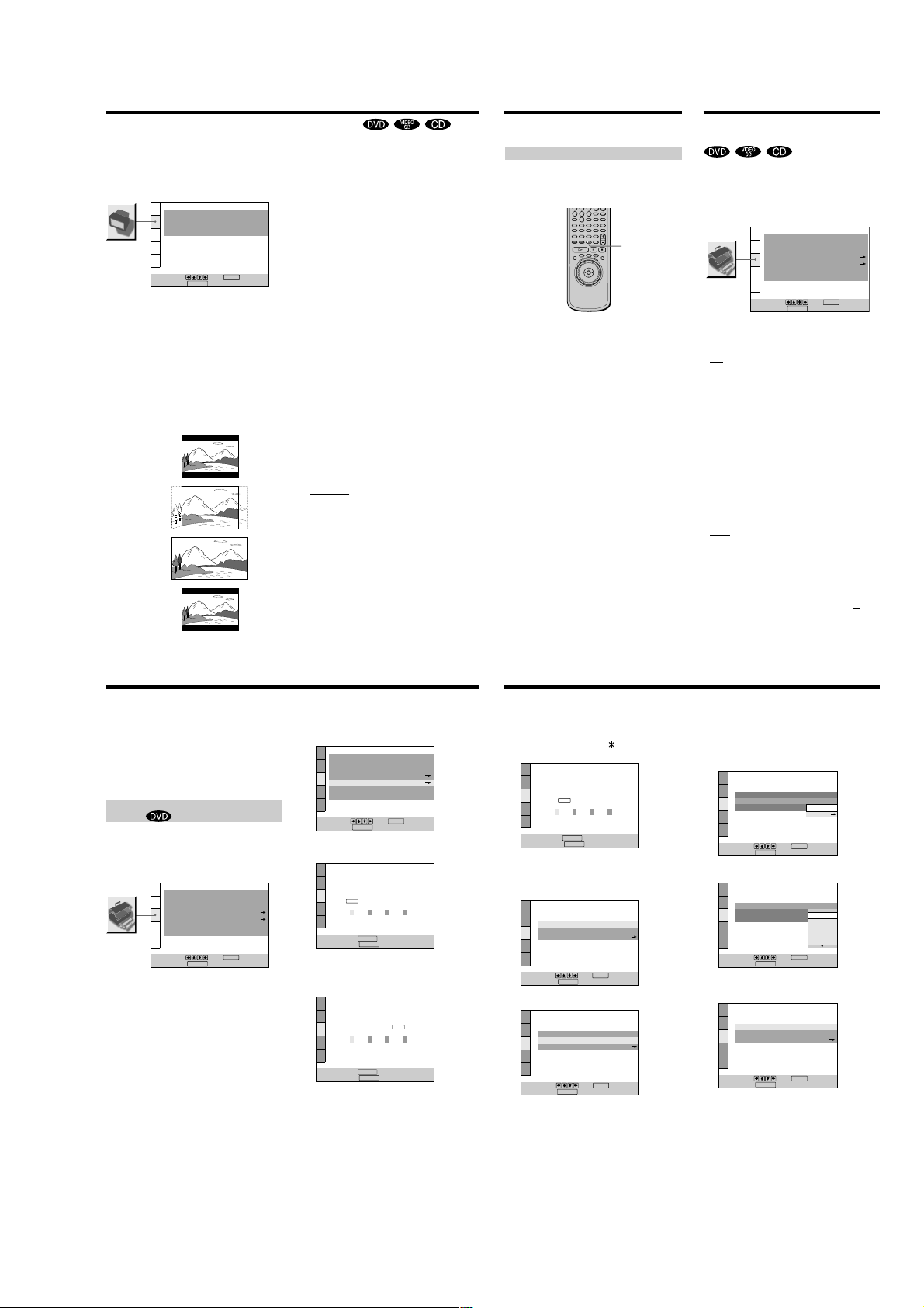
x TV TYPE
Selects the aspect ratio of the TV to be connected.
•
4:3 LETTER BOX: select this when you connect a normal
TV to the player. Displays a wide picture with bands on
the upper and lower portions of the screen.
• 4:3 PAN SCAN: select this when you connect a normal
TV to the player. Displays the wide picture on the
whole screen automatically and cuts off the portions
that do not fit.
• 16:9/4:3 WIDE MODE: select this when you connect a
wide-screen TV to the player or when you connect a TV
with the WIDE MODE function to the player (displays a
wide picture with bands displayed on the upper and
lower portions of the screen).
4:3 LETTER BOX
4:3 PAN SCAN
16:9
4:3 WIDE MODE
DISPLAY
4:3 LETTER BOX
JACKET PICTURE
ENTER
Note
Depending on the DVD, “4:3 LETTER BOX“ may be selected
automatically instead of “4:3 PAN SCAN” and vice versa.
x SCREEN SAVER
Turns on and off the screen saver. If you turn on the
screen saver, the screen saver image appears when you
leave the player or the remote in pause or stop mode for
ON
15 minutes, or when you play back a CD for more than 15
minutes. The screen saver will help prevent your display
device from becoming damaged.
•
ON: turns on the screen saver.
• OFF: turns off the screen saver.
x BACKGROUND
Selects the background color or picture on the TV screen
in stop mode or while playing a CD.
•
JACKET PICTURE: The jacket picture appears in the
background, but only when the jacket picture is already
recorded on the disc.
PICTURE MEMORY: Your favorite picture appears in
•
the background. For an explanation of how to store
your favorite scene recorded on the disc for the
background picture, see the following section “Storing a
picture in memory.”
• GRAPHICS: A preset picture stored in the player
appears in the background.
• BLUE: The background color is blue.
• BLACK: The background color is black.
Note
If a disc which does not contain the jacket picture is played while
“BACKGROUND” is set to “JACKET PICTURE,“ the picture
stored in the player will automatically appear in the background.
x STARTUP SCREEN
Selects the startup screen. The startup screen image you
selected appears when you turn on the player.
•
STANDARD: The standard startup screen in the
player’s memory appears.
• PICTURE MEMORY: Your favorite picture appears in
the startup screen. For an explanation of how to store
your favorite scene recorded on the disc for the startup
screen, see the following section “Storing a picture in
memory.”
If you select PICTURE MEMORY before setting a
picture in memory, the standard startup screen will
appear.
Storing a picture in memory
During playback, when you find the scene to be stored
in memory, press PICTURE MEMORY on the remote.
The picture is stored in memory.
8
9
0
PICTURE
MEMORY
Notes
• The player can store only one scene in memory. The stored
picture appears in both the background and the startup screen.
• Depending on the DVD, some scenes cannot be stored in
memory when using the remote.
• When the picture is stored in memory by pressing PICTURE
MEMORY, the picture stored before is erased.
• If you operate this player while the picture is being stored in
memory, the player will fail to store the picture.
Custom Settings
(CUSTOM SETUP)
“CUSTOM SETUP” allows you to set the playback
conditions.
The default settings are underlined.
Select “CUSTOM SETUP” in the setup display.
CUSTOM SETUP
AUTO PLAY:
DIMMER:
PAUSE MODE:
BOOKMARK RESET
PARENTAL CONTROL
PLAYBACK MEMORY:
TRACK SELECTION:
To set, press , then .
DISPLAY
To quit, press .
x AUTO PLAY
Selects the Auto Play setting when you connect the AC
power cord to the AC outlet.
•
OFF: does not use “TIMER,” “DEMO1” or “DEMO2” to
start playback.
• TIMER: starts playing when the player is turned on, or
at any time you want when connected to a timer (not
supplied). Set the timer when the player is in standby
mode (the power indicator lights up in red).
• DEMO1: starts playing the first demonstration
automatically.
• DEMO2: starts playing the second demonstration
automatically.
x DIMMER
Adjusts the lighting of the front panel display.
•
BRIGHT: makes the front panel display bright.
• DARK: makes the front panel display dark.
• OFF: turns off the lighting of the front panel display.
x PAUSE MODE (DVD only)
Selects the picture in pause mode.
•
AUTO: A picture, including subjects that move
dynamically, is output with no jitter. Normally select
this position.
• FRAME: A picture including subjects that do not move
dynamically is output with high resolution.
x BOOKMARK RESET,
Select “BOOKMARK RESET.” The BOOKMARK reset
display appears. And then press ENTER to reset
bookmarks.
ENTER
OFF
BRIGHT
AUTO
OFF
all
ON
60
Custom Settings (CUSTOM SETUP)
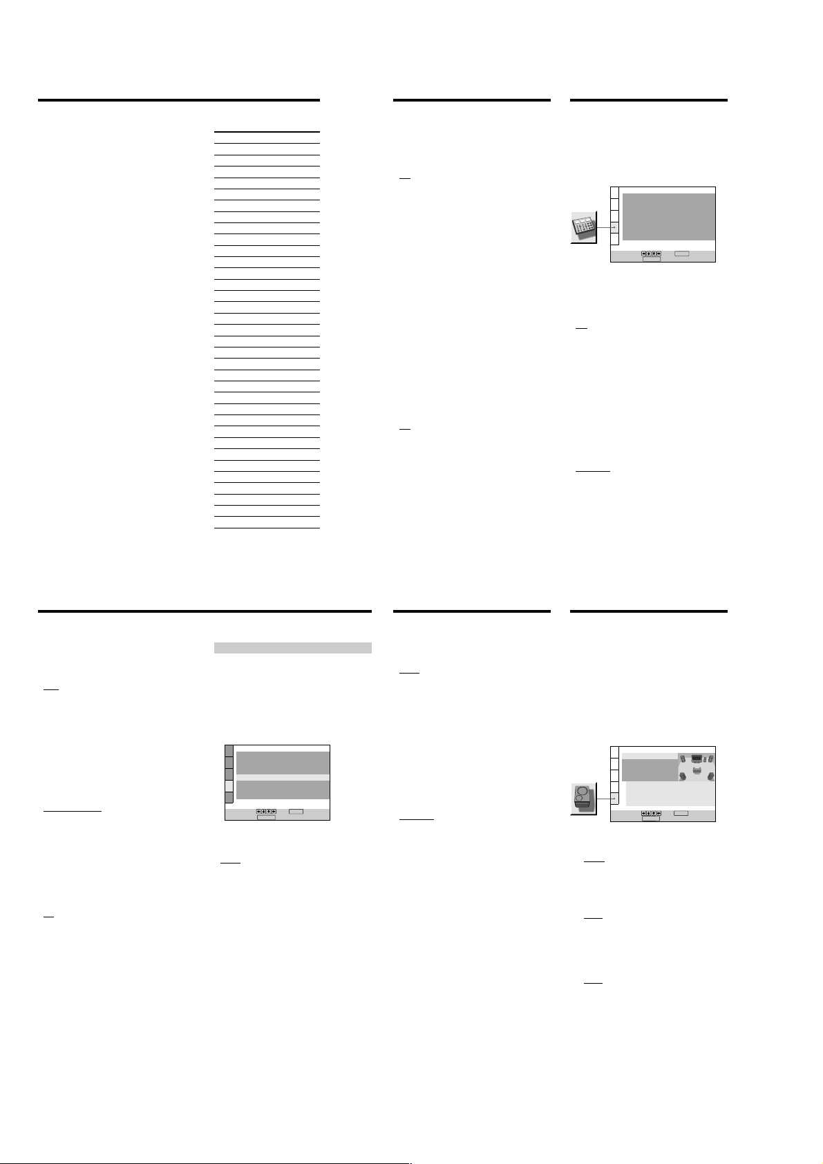
x PARENTAL CONTROL,
Sets a password and playback limitation level for DVDs
with playback limitation for children.
The same password is used for both Parental Control and
Custom Parental Control (page 43) .
For details, see “Limiting Playback by Children (Parental
Control) .”
Limiting Playback by Children (Parental
Control)
Playback of some DVDs can be limited depending on the
age of the users. The “Parental Control” function allows
you to set a playback limitation level.
Select “CUSTOM SETUP” in the setup display.
CUSTOM SETUP
AUTO PLAY:
DIMMER:
PAUSE MODE:
BOOKMARK RESET
PARENTAL CONTROL
PLAYBACK MEMORY:
TRACK SELECTION:
To set, press , then .
DISPLAY
To quit, press .
ENTER
OFF
BRIGHT
AUTO
OFF
ON
1
Select “PARENTAL CONTROL” using M/m, then press
ENTER.
CUSTOM SETUP
AUTO PLAY:
DIMMER:
PAUSE MODE:
BOOKMARK RESET
PARENTAL CONTROL
PLAYBACK MEMORY:
TRACK SELECTION:
To set, press , then .
DISPLAY
To quit, press .
x When you have not entered a password
The display for entering a password appears.
CUSTOM SETUP
PARENTAL CONTROL
Enter a new 4-digit password, then
ENTER
.
press
RETURN
To return, press .
DISPLAY
To cancel, press .
x When you have already registered a password
The display for confirming the password appears. Skip
Step 2.
CUSTOM SETUP
PARENTAL CONTROL
Enter password, then press
RETURN
To return, press .
DISPLAY
To cancel, press .
ENTER
.
OFF
BRIGHT
AUTO
ON
OFF
ENTER
2
Enter a password in 4 digits using the number
buttons, then press ENTER.
The digits change to asterisks (
confirming the password appears.
CUSTOM SETUP
PARENTAL CONTROL
To confirm,enter password again,
ENTER
then press
.
RETURN
To return, press .
DISPLAY
To cancel, press .
3
To confirm your password, enter it again using the
number buttons, then press ENTER.
The display for setting the playback limitation level
and changing the password appears.
CUSTOM SETUP
PARENTAL CONTROL
LEVEL:
STANDARD:
CHANGE PASSWORD
To set, press , then .
DISPLAY
To quit, press .
4
Select “STANDARD” using M/m, then press ,.
CUSTOM SETUP
PARENTAL CONTROL
LEVEL:
STANDARD:
CHANGE PASSWORD
To set, press , then .
DISPLAY
To quit, press .
), and the display for
ENTER
ENTER
OFF
USA
OFF
USA
5
Select a geographic area as the playback limitation
level standard using M/m, then press ,.
When you select “OTHERS,,” select and enter the
standard code in the table on the next page using the
number buttons.
CUSTOM SETUP
PARENTAL CONTROL
LEVEL:
STANDARD:
CHANGE PASSWORD
To set, press , then .
DISPLAY
To quit, press .
6
Select “LEVEL” using M/m, then press ,.
CUSTOM SETUP
PARENTAL CONTROL
LEVEL: OFF
STANDARD:
CHANGE PASSWORD
To set, press , then .
DISPLAY
To quit, press .
7
Select the level you want using M/m, then press
ENTER.
CUSTOM SETUP
PARENTAL CONTROL
LEVEL:
STANDARD:
CHANGE PASSWORD
To set, press , then .
DISPLAY
To quit, press .
ENTER
ENTER
ENTER
OTHERS
OFF
8:
NC17
7:
6:
5:
4: PG13
USA
OFF
USA
USA
R
The lower the value, the more strict the limitation.
To return to the normal screen
Press DISPLAY.
To turn off the Parental Control function and play
the DVD after entering your password
Set “LEVEL” to “OFF” in Step 7, then press H.
61
62
63
1-15
Custom Settings (CUSTOM SETUP)
To change the password
1 After Step 3, select “CHANGE PASSWORD” using
M/m, then press , or ENTER.
The display for changing the password appears.
2 Follow Steps 2 and 3 to enter a new password.
Playing a disc which is blocked by the playback
limitation level
1 Insert the disc and press H.
The PARENTAL CONTROL display appears.
2 Enter your 4-digit password using the number buttons,
then press ENTER.
The player starts playback.
When you stop playing the DVD, the level returns to
the original level.
z
If you forget your password
Enter the 6-digit number “199703” whenever the PARENTAL
CONTROL display asks you for your password, then press
ENTER. The display will ask you to enter a new 4-digit
password.
Notes
• When you play DVDs which do not have the Parental Control
function, playback cannot be limited on this player.
• If you do not set a password, you cannot change the settings
for playback limitation.
• Depending on the DVD, you may be asked to change the
parental control level while playing the disc. In this case, enter
your password, then change the level.
When you stop playing the DVD, the level returns to the
original level.
• The same password is used for both Parental Control and
Custom Parental Control (page 43).
64
Standard Code number
Argentina 2044
Australia 2047
Austria 2046
Belgium 2057
Brazil 2070
Canada 2079
Chile 2090
China 2092
Denmark 2115
Finland 2165
France 2174
Germany 2109
Hong Kong 2219
India 2248
Indonesia 2238
Italy 2254
Japan 2276
Korea 2304
Malaysia 2363
Mexico 2362
Netherlands 2376
New Zealand 2390
Norway 2379
Pakistan 2427
Philippines 2424
Portugal 2436
Russia 2489
Singapore 2501
Spain 2149
Sweden 2499
Switzerland 2086
Taiwan 2543
Thailand 2528
United Kingdom 2184
x PLAYBACK MEMORY
The player can store the SUBTITLE, VIDEO EQUALIZER,
and other settings of each disc for up to 300 discs
(Playback Memory).
Set the Playback Memory function on or off.
•
ON : stores the settings in memory when you eject the
disc.
• OFF : does not store the settings in memory.
The following settings are stored in memory by the
Playback Memory function.
– AUDIO (page 35)*
– SUBTITLE (page 37)*
– ANGLE (page 38)*
– VIRTUAL 3D SURROUND (page 39)
– VIDEO EQUALIZER (page 51)
– DIGITAL VIDEO ENHANCER (page 52)
* DVD only
Notes
• The player can store the settings of up to 300 discs. When you
store the setting of disc number 301, the first disc setting is
canceled.
• Depending on the DVD, the information stored in the disc
takes priority over the Playback Memory settings and the
function does not work.
• Do not turn off the player by pressing !. Doing so may cancel
the settings. When you turn off the player, press x first to stop
playback and then press ?/1 on the remote. After the power
indicator lights up in red and the player enters standby mode,
press ! on the player.
x TRACK SELECTION
Gives the sound track which contains the highest number
of channels priority when you play a DVD on which
multiple audio formats (PCM, DTS or Dolby Digital
format) are recorded.
•
OFF : No priority given.
• AUTO : Priority given.
Notes
• When you set this item to “AUTO,” the language may change
depending on the “AUDIO” settings in “LANGUAGE SETUP.”
The “TRACK SELECTION“ setting has higher priority than the
“AUDIO” settings in “LANGUAGE SETUP” (page 59).
• If you set “DTS” in “AUDIO SETUP” to “D-PCM”, the DTS
sound track is not played even if you set this item to “AUTO”
and the highest-numbered audio channel is recorded in DTS
format.
• If PCM, DTS and Dolby Digital sound tracks have the same
number of channels, the player selects PCM, DTS and Dolby
Digital sound tracks in this order.
• Depending on the DVD, the audio channel with priority may
be predetermined. In this case, you cannot give priority to the
DTS or Dolby Digital format by selecting “AUT
O.”
Settings for the Sound
(AUDIO SETUP)
“AUDIO SETUP” allows you to set the sound according
to the playback conditions.
The default settings are underlined.
Select “AUDIO SETUP” in the setup display.
x AUDIO ATT (attenuation)
If the playback sound is distorted, set this item to “ON.”
The player reduces the audio output level.
Selects the setting of the output from the AUDIO OUT
(1, 2) connectors according to the audio equipment to be
connected.
•
OFF: turns off the audio attenuation. Normally select
this position.
• ON: reduces the audio output level so that no sound
distortion occurs. Select this when the playback sound
from the built-in TV speakers is distorted.
Note
The setting does not affect the output from the DIGITAL OUT
OPTICAL and COAXIAL connectors.
x AUDIO DRC (Dynamic Range Control)
(DVD only)
Makes the sound clear when the volume is turned down
when playing a DVD. This function works only when
you play a DVD which has the AUDIO DRC function.
This affects the output from the DIGITAL OUT connectors
only when “DOLBY DIGITAL” is set to “D-PCM” and
“DTS” to “D-PCM” in ”DIGITAL OUT.”
•
STANDARD: Normally select this position.
• TV MODE: makes the low sounds clear even if you turn
the volume down. It is especially recommended when
you listen to the sound using the speakers of the TV.
• WIDE RANGE: It gives you the feeling of being at a live
performance. This function only works when you are
playing a Dolby Digital disc and is more effective when
you connect 6 speakers using the 5.1 channel
connectors. When you use high quality speakers, it is
even more effective.
Note
When you play DVDs without the AUDIO DRC function, there
may be no effect on the sound.
AUDIO SETUP
AUDIO ATT:
AUDIO DRC:
CENTER SPEAKER EQ:
DOWNMIX:
DIGITAL OUT:
DOLBY DIGITAL:
DTS:
48kHz/96kHz PCM:
To set, press , then .
DISPLAY
To quit, press .
STANDARD
DOLBY SURROUND
ENTER
OFF
FLAT
ON
D-PCM
D-PCM
48kHz/16bit
65
Settings for the Sound (AUDIO SETUP)
x CENTER SPEAKER EQ (equalizer)
Makes the spoken track clear by changing the frequency
response when speech is difficult to hear. A center speaker
must be connected to the CENTER connector of 5.1CH
OUTPUT for this function to work.
•
FLAT: outputs the spoken track as it was recorded.
• ENHANCED: enhances the spoken track only.
• SOFT: makes the sound softer by rounding out the
sound frequency above 8 kHz. Select this when the
spoken track sounds shrill.
x DOWNMIX
Switches the mixing down methods when you play a
DVD on which rear signal components such as LS, RS, or
S are recorded in Dolby Digital or DTS format. For details
on the rear signal components, see “Displaying the audio
information of the disc” (page 36).
This affects the output from the DIGITAL OUT connectors
only when “DOLBY DIGITAL” is set to “D-PCM” and
“DTS” to “D-PCM” in ”DIGITAL OUT.”
•
DOLBY SURROUND: when the player is connected to
an audio component that conforms to Dolby Surround
(Pro Logic). The output signals which reproduce the
Dolby Surround (Pro Logic) effect are mixed down to 2
channels.
• NORMAL: when the player is connected to an audio
component that does not conform to Dolby Surround
(Pro Logic). The signals without the Dolby Surround
(Pro Logic) effect are output.
x DIGITAL OUT
Selects output signals via the DIGITAL OUT OPTICAL
and COAXIAL connectors.
•
ON: Normally select this position. When you select
“ON,” set “DOLBY DIGITAL,” “DTS” and “48kHz/
96kHz PCM.“ For details on setting these items, see
“Setting the Digital Output Signal.”
• OFF: when the player does not output the sound signals
via the DIGITAL OUT OPTICAL and COAXIAL
connectors, the influence of the digital circuit upon the
analog circuit is at a minimum.
Note
When you select “OFF,” you cannot set “DOLBY DIGITAL,”
“DTS” and “48kHz/96kHz PCM.“
Setting the Digital Output Signal
Switches the methods of outputting audio signals when
you, connect 1. a digital component such as a receiver
(amplifier) having a digital connector, 2. an audio
component having a built-in decoder (Dolby Digital or
DTS), 3. a DAT or MD via the DIGITAL OUT OPTICAL or
COAXIAL connector using an optical or coaxial digital
connecting cord. For connection details, see page 11.
You cannot adjust “DOLBY DIGITAL,” “DTS” and
“48kHz/96kHz PCM” if you set “DIGITAL OUT” to
“OFF.”
AUDIO SETUP
AUDIO ATT:
AUDIO DRC:
CENTER SPEAKER EQ:
DOWNMIX:
DIGITAL OUT:
DOLBY DIGITAL:
DTS:
48kHz/96kHz PCM:
To set, press , then .
To quit, press .
DISPLAY
x DOLBY DIGITAL
Selects the Dolby Digital signals to be output via the
DIGITAL OUT OPTICAL and COAXIAL connectors.
•
D-PCM (Downmix PCM): when the player is connected
to an audio component lacking a built-in Dolby Digital
decoder. If you play Dolby Digital sound tracks, the
output audio signals are mixed down to 2 channels.
You can select whether the signals conform to Dolby
Surround (Pro Logic) or not by making adjustments to
the “DOWNMIX” item in “AUDIO SETUP.”
• DOLBY DIGITAL: when the player is connected to an
audio component with a built-in Dolby Digital decoder.
If the player is connected to an audio component
lacking a built-in Dolby Digital decoder, do not set this.
Otherwise, when you play the Dolby Digital sound
track, a loud noise (or no sound) will come out from the
speakers, affecting your ears or causing the speakers to
be damaged.
OFF
STANDARD
FLAT
DOLBY SURROUND
D-PCM
D-PCM
48kHz/16bit
ENTER
ON
x DTS
Selects the DTS signals to be output via the DIGITAL OUT
OPTICAL and COAXIAL connectors.
•
D-PCM: when the player is connected to an audio
component lacking a built-in DTS decoder. If you play
DTS sound tracks, the player outputs stereo signals via
the DIGITAL OUT OPTICAL and COAXIAL
connectors.
• DTS: when the player is connected to an audio
component having a built-in DTS decoder.
If the player is connected to an audio component
lacking a built-in DTS decoder, do not set this.
Otherwise, when you play the DTS sound track, a loud
noise (or no sound) will come out from the speakers,
affecting your ears or causing the speakers to be
damaged.
x 48kHz/96kHz PCM (DVD only)
Selects the sampling frequency of the audio signal to be
output via the DIGITAL OUT OPTICAL and COAXIAL
connectors.
•
48kHz/16bit: The audio signals of DVDs are always
converted to 48 kHz/16 bit.
• 96kHz/24bit: All types of signals including 96 kHz/24
bit are output in their original format. However, if the
signal is encrypted for copyright protection purposes,
the signal is only output as 48 kHz/16 bit.
Notes
• If you select “96kHz/24bit” when a receiver (amplifier) which
cannot accept 96 kHz is connected to the player, no sound or a
loud noise will come out from the speakers.
• Even if you set “48kHz/96kHz PCM” in “AUDIO SETUP” to
“96kHz/24bit,” the sampling frequency is converted to 48
kHz/16 bit when a VIRTUAL 3D SURROUND mode is
selected.
• The analog audio signals from the AUDIO OUT connectors are
not affected by this setting and keep their original sampling
equency level.
fr
Settings for the Speakers
(SPEAKER SETUP)
To obtain the best possible surround sound when you use
the 5.1CH OUTPUT connectors, use the SPEAKER SETUP
display to first specify the size of the speakers you have
connected and their distance from your listening position.
Then set the balance and level. Use the test tone to adjust
the volume of the speakers to the same level.
For speaker hookup instructions, see page 12.
The default settings are underlined.
Select “SPEAKER SETUP” in the setup display.
SPEAKER SETUP
SIZE:
DISTANCE:
BALANCE:
LEVEL:
TEST TONE:
To set, press , then .
To quit, press .
x SIZE
Selects the size of the speakers to be connected.
• FRONT
—
LARGE: Normally select this.
— SMALL: When the sound cracks or the surround
sound effects are difficult to hear, select this. This
activates the Dolby Digital bass redirection circuitry
and outputs the bass frequencies of the speaker from
the subwoofer.
• CENTER
—
NONE: If you do not connect a center speaker, select
this.
— LARGE: Normally select this.
— SMALL: When the sound cracks, select this. This
activates the Dolby Digital bass redirection circuitry
and outputs the bass frequencies of the center
speaker from other speakers .
•REAR
—
NONE: If you do not connect rear speakers, select
this.
— LARGE (REAR/SIDE): Normally select either of
these according to the rear speaker’s position*.
— SMALL (REAR/SIDE): When the sound cracks or the
surround sound effects are difficult to hear, select
either of these according to the rear speaker’s
position*. This activates the Dolby Digital bass
redirection circuitry and outputs the bass frequencies
of the rear speaker from other speakers .
FRONT:
CENTER:
REAR:
SUBWOOFER:
SETUP.DISPLAY
OFF
LARGE(REAR
ENTER
LARGE
LARGE
YES
)
66
67
1-16
Settings for the Speakers (SPEAKER SETUP)
• SUBWOOFER
—
NONE: If you do not connect a subwoofer, select
this. This activates the Dolby Digital bass redirection
circuitry and outputs the LFE signals from the front
speakers as long as the front speaker size is set to
“LARGE.”
— YES: If you connect a subwoofer, select this to output
the LFE (low frequency effect) channel from the
subwoofer.
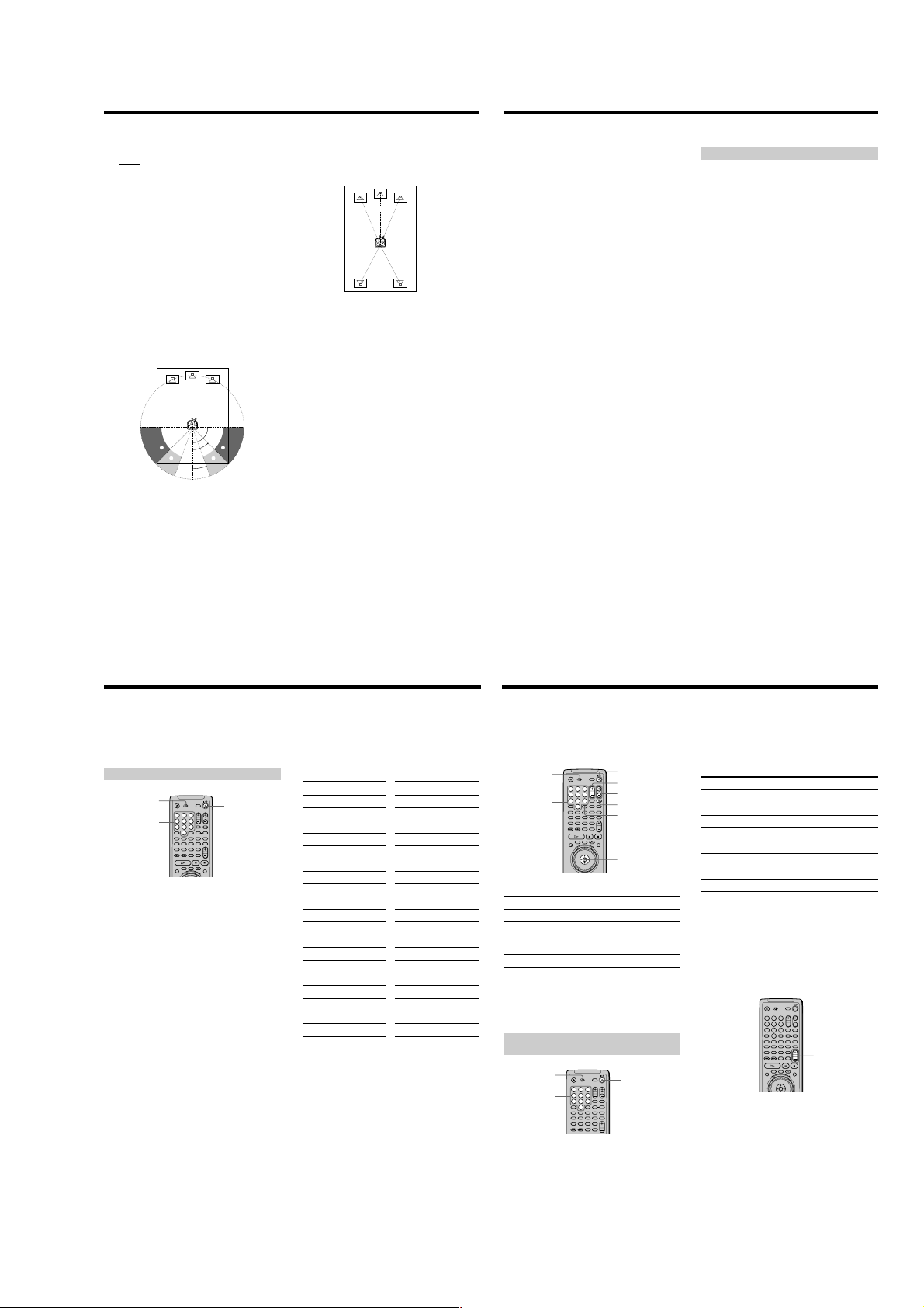
* Rear speaker position
Specify the location of the rear speakers for correct
“VIRTUAL REAR SHIFT,” “VIRTUAL MULTI REAR” and
“VIRTUAL MULTI DIMENSION” effects. These effects
can be found in “VIRTUAL 3D SURROUND” of the
Control Menu display.
• SIDE: If the location of the rear speakers corresponds to
section A in the illustration below.
• REAR: If the location of the rear speakers corresponds
to section B in the illustration below.
This setting affects only the “VIRTUAL REAR SHIFT,”
“VIRTUAL MULTI REAR” and “VIRTUAL MULTI
DIMENSION” mode.
90°
A
B
Notes
• The cut off frequency for the subwoofer is fixed at 120 Hz.
• If your speakers are too small to reproduce low bass
frequencies, please set all speaker settings to “SMALL” and
utilize a subwoofer for low frequency sound.
A
45°
B
20°
x DISTANCE
The default distance setting for the speakers in relation to
the listening position is shown below.
12ft/3.6m 12ft/3.6m
10ft/3.0m 10ft/3.0m
You can vary the distance of each speaker as follows. The
default adjustments are in parentheses. Be sure to change
the value in the setup display when you move the
speakers.
• FRONT (12ft/3.6m)
Front speaker distance can be set in 1 foot (0.3 meter)
increments from 4 to 50 feet (1.2 to 15.2 meters).
Distance is measured from the front speaker to the
listening position.
• CENTER (12ft/3.6m)
Center speaker distance can be set in 1 foot (0.3 meter)
increments. Place the center speaker directly between
the front speakers. You can move it up to 2 feet (0.6
meter) backwards or 5 feet (1.5 meters) forwards if
necessary.
• REAR (10ft/3.0m)
Rear speaker distance can be set in 1 foot (0.3 meter)
increments. Place the speakers behind the listening
position at a distance equal to the front speaker
distance. If necessary you can move the rear speakers
up to 16 feet (5 meters) closer to your listening position.
To return to the default setting
Select the item, then press CLEAR.
Notes
• If each of the front or rear speakers are not placed at an equal
distance from your listening position, set the distance
according to the closest speaker.
• Do not place the rear speakers farther away from your listening
position than the front speakers.
x BALANCE
You can vary the balance of the left and right speakers as
follows. Be sure to set “TEST TONE” to “ON” for easy
adjustment (see x TEST TONE below). The default
adjustments are in parentheses.
• FRONT (0dB)
Adjust the balance between the front left and right
speakers (–6dB [L] to +6dB [R], 0.5dB increments).
• REAR (0dB)
Adjust the balance between the rear left and right
speakers (–6dB [L] to +6dB [R], 0.5dB increments).
To return to the default setting
Select the item, then press CLEAR.
x LEVEL
You can vary the level of each speaker as follows. The
front speaker level becomes the criterion for adjusting the
other speakers. Be sure to set “TEST TONE” to “ON” for
easy adjustment (see x TEST T
adjustments are in parentheses.
• CENTER (0dB)
Adjust the level of the center speaker (–6dB to +6dB,
0.5dB increments).
• REAR (0dB)
Adjust the level of the rear speakers (–6dB to +6dB,
0.5dB increments).
• SUBWOOFER (0dB)
Adjust the level of the subwoofer (–10dB to +10dB,
0.5dB increments).
To return to the default setting
Select the item, then press CLEAR.
x TEST TONE
The speakers will emit a test tone. Use this when you use
the 5.1CH OUTPUT connectors and adjust the BALANCE
and LEVEL.
•
OFF: The test tone is not emitted from the speakers.
• ON: The test tone is emitted from each speaker in
sequence. When you select one of the “SPEAKER
SETUP” items, the test tone is emitted from both left
and right speakers simultaneously.
Note
When you adjust the speaker settings, the sound cuts off for a
moment.
ONE below). The default
Adjusting the speaker volume
1
After you stop playback, select “SPEAKER SETUP”
in the setup display.
2
Select “TEST TONE” and set “TEST TONE” to “ON.”
You will hear the test tone from each speaker in
sequence.
3
From your listening position, select “BALANCE” or
“LEVEL” and adjust the value of “BALANCE” using
</, and “LEVEL” using M/m.
The test tone is emitted from both left and right
speakers simultaneously.
4
Select “TEST TONE” and set “TEST TONE” to “OFF”
to turn off the test tone.
To adjust the volume of all the speakers at one
time
Use the receiver’s (amplifier’s) volume control.
68
Controlling Your TV or AV Receiver (Amplifier) with the
Supplied Remote Z
By adjusting the remote signal, you can control your TV
or AV receiver (amplifier) with the supplied remote.
Controlling TVs with the remote
TV/DVD
switch
1
4
Number
7
buttons
1
Slide the TV/DVD switch to TV.
2
Hold down ?/1, and enter your TV’s manufacturer’s
code (see the table) using the number buttons.
3
Release ?/1.
?/1
2
3
5
6
8
9
0
Code numbers of controllable TVs
If more than one code number is listed, try entering them
one at a time until you find the one that works with your
TV.
Manufacturer Code number
Sony (default) 01
Akai 04
AOC 04
Centurion 12
Coronado 03
Curis-Mathes 12
Daytron 12
Emerson 03,04,14
Fisher 11
General Electric 06, 10
Gold Star 03,04,17
Hitachi 02,03
J.C.Penney 04,12
JVC 09
KMC 03
Magnavox 03,08,12
Marantz 04,13
MGA/Mitsubishi 04,12,13,17
NEC 04, 12
Notes
• If you enter a new code number, the code number previously
entered will be erased.
• When you replace the batteries of the remote, the code number
may be reset to the default setting. Reset the appropriate code
number.
Manufacturer Code number
Panasonic 06,19
Philco 03,04
Philips 08
Pioneer 16
Portland 03
Quasar 06,18
Radio Shack 05,14
RCA 04,10
Sampo 12
Sanyo 11
Scott 12
Sears 07,10,11
Sharp 03,05,18
Sylvania 08,12
Teknika 03,08,14
Toshiba 07
Wards 03,04,12
Yorx 12
Zenith 15
Controlling the TV
You can control your TV using the buttons below. When
you set the TV/DVD switch to TV, you can also control
the number, ?/1 and ENTER buttons.
TV/DVD
switch
1
4
7
Number
buttons
By pressing
?/1
TV/VIDEO
VOL
CH
Number buttons
and ENTER
Note
Depending on the TV, you may not be able to control your TV or
to use some of the buttons above.
Controlling AV receivers (amplifiers) with
the remote
TV/DVD
switch
Number
buttons
1
Slide the TV/DVD switch to DVD.
2
Hold down ?/1, and enter your AV receiver’s
manufacturer’s code (see the table) using the
number buttons.
3
Release ?/1.
?/1
VOL
2
3
5
6
CH
8
9
TV/VIDEO
0
ENTER
ENTER
You can
Turn the TV on or off
Switch the TV’s input source between
the TV and other input sources
Adjust the volume of the TV
Select the channel of the TV
Select the channel of the TV
1
4
7
?/1
2
3
5
6
8
9
0
Code numbers of controllable AV receivers
(amplifier)
If more than one code number is listed, try entering them
one at a time until you find the one that works with your
AV receiver (amplifier).
Manufacturer Code number
Sony 91 (default), 89
Denon 84, 85, 86
Kenwood 92, 93
Onkyo 81, 82, 83
Pioneer 99
Sansui 87
Technics 97, 98
Yamaha 94, 95, 96
Notes
• If you enter a new code number, the code number previously
entered will be erased.
• When you replace the batteries of the remote, the code number
may be reset to the default setting. Reset the appropriate code
number.
Controlling the AV receiver (amplifier)
You can change the volume of the AV receiver (amplifier)
using AV VOL.
1
2
3
4
5
6
7
8
9
0
AV VOL
Notes
• Depending on the AV receiver (amplifier), you may not be able
to control your AV receiver (amplifier).
• You can control the AV receiver (amplifier) regardless of the
position of the TV/DVD switch.
69
70
71
1-17
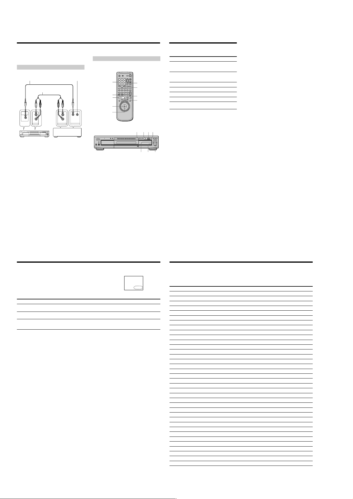
Controlling the CD Changer (Mega Control)
You can control a Sony CD changer of 5/50/200/300 discs
connected to the MEGA CONTROL jack of the player.
Connecting the CD changer
Do not connect
CONTROL A1 cable
(not supplied)
MEGA
CONTROL
This player
Audio cable (not supplied)
L
R
AUDIO IN
anything to the other
CONTROL A1 jack.
L
R
AUDIO OUT
CONTROL A1
Sony CD changer
(5/50/200/300 discs)
Controlling the CD changer
The controls indicated below are effective while the
MEGA CONTROL button is lit.
1
2
3
4
5
Number buttons
./>
ENTER
</M/m/,
1
Set the command mode selector of the CD changer
to “CD 3.”
2
Turn on the player and the CD changer.
3
Press MEGA CONTROL (MEGA CTL).
The MEGA CONTROL button on the front panel lights
up and the display shows the current disc number in
the CD changer.
4
Select the play mode you want on the CD changer.
5
Press H on the player to start playing.
Playback starts and the display shows the current disc
and track numbers and the playing time of the track.
While the MEGA CONTROL button on the front panel
is lit, you can control the CD changer with the controls
on the player as follows:
6
8
9
0
./>
MEGA CONTROL
MEGA CTL
ENTER
X
x
HXx
</M/
m/,
7
H
To
Select a disc in
continuous play
mode
Skip by 10 discs in
continuous play
mode
Stop
Pause
Resume play after pause
Go to the next track
Go back to the preceding
track
To control the player again
Press MEGA CONTROL (MEGA CTL).
The MEGA CONTROL (MEGA CTL) button on the player
turns off and you can control the player.
Notes
• Connect only a Sony 5/50/200/300 CD changer to the MEGA
CONTROL jack.
• You cannot locate a particular point on a CD’s track using the
controls on the player.
• Depending on the CD changer, some controls on the player
ENTER
may not operate the CD changer as they do the player.
• You cannot control the player when the MEGA CONTROL
button on the front is lit.
• The player will not enter Resume Play after the MEGA
CONTROL button on the front has been turned on and off.
• You cannot control the CD changer right after turning on the
player or connecting the CD changer. Wait a few seconds until
the player recognizes the CDs.
• When the MEGA CONTROL button is lit, you cannot use the
ol menu.
Contr
Operation
Press the number button on the
remote and ENTER, or M/m and
ENTER.
Press </,.
Press x.
Press X.
Press X or H.
Press >.
Press ..
72
Self-diagnosis function
When the self-diagnosis function activates to prevent the player from
malfunctioning, a five-character service number (combination of a letter and
digits) flashes on the screen and on the front panel display. In this case, check the
following table.
First three characters
C13
C31
Exx (xx is any number)
Cause and/or Corrective Action
•The disc is dirty.
, Clean the disc with a cleaning cloth. (page 6)
•The disc is not inserted correctly.
, Open the disc tray and insert the disc correctly.
•To prevent a malfunction, the player has performed the self-diagnosis function.
,When you contact your Sony dealer or local authorized Sony service facility, give
the 5-character service number. (example: E:61:10)
C:13:00
Language Code List
For details, see pages 37, 59.
Code Language Code Language Code Language Code Language
1027 Afar
1028 Abkhazian
1032 Afrikaans
1039 Amharic
1044 Arabic
1045 Assamese
1051 Aymara
1052 Azerbaijani
1053 Bashkir
1057 Byelorussian
1059 Bulgarian
1060 Bihari
1061 Bislama
1066 Bengali; Bangla
1067 Tibetan
1070 Breton
1079 Catalan
1093 Corsican
1097 Czech
1103 Welsh
1105 Danish
1109 German
1130 Bhutani
1142 Greek
1144 English
1145 Esperanto
1149 Spanish
1150 Estonian
1151 Basque
1157 Persian
1165 Finnish
1166 Fiji
1171 Faroese
1174 French
1181 Frisian
1183 Irish
1186 Scots Gaelic
1194 Galician
1196 Guarani
1203 Gujarati
1209 Hausa
1217 Hindi
1226 Croatian
1229 Hungarian
1233 Armenian
1235 Interlingua
1239 Interlingue
1245 Inupiak
1248 Indonesian
1253 Icelandic
1254 Italian
1257 Hebrew
1261 Japanese
1269 Yiddish
1283 Javanese
1287 Georgian
1297 Kazakh
1298 Greenlandic
1299 Cambodian
1300 Kannada
1301 Korean
1305 Kashmiri
1307 Kurdish
1311 Kirghiz
1313 Latin
1326 Lingala
1327 Laothian
1332 Lithuanian
1334 Latvian; Lettish
1345 Malagasy
1347 Maori
1349 Macedonian
77
The language spellings conform to the ISO 639: 1988 (E/F) standard.
1350 Malayalam
1352 Mongolian
1353 Moldavian
1356 Marathi
1357 Malay
1358 Maltese
1363 Burmese
1365 Nauru
1369 Nepali
1376 Dutch
1379 Norwegian
1393 Occitan
1403 (Afan) Oromo
1408 Oriya
1417 Punjabi
1428 Polish
1435 Pashto; Pushto
1436 Portuguese
1463 Quechua
1481 Rhaeto-Romance
1482 Kirundi
1483 Romanian
1489 Russian
1491 Kinyarwanda
1495 Sanskrit
1498 Sindhi
1501 Sangho
1502 Serbo-Croatian
1503 Singhalese
1505 Slovak
1506 Slovenian
1507 Samoan
1508 Shona
1509 Somali
1511 Albanian
1512
Serbian
73
1513 Siswati
1514 Sesotho
1515 Sundanese
1516 Swedish
1517 Swahili
1521 Tamil
1525 Telugu
1527 Tajik
1528 Thai
1529 Tigrinya
1531 Turkmen
1532 Tagalog
1534 Setswana
1535 Tonga
1538 Turkish
1539 Tsonga
1540 Tatar
1543 Twi
1557 Ukrainian
1564 Urdu
1572 Uzbek
1581 Vietnamese
1587 Volapük
1613 Wolof
1632 Xhosa
1665 Yoruba
1684 Chinese
1697 Zulu
1703 Not specified
81
1-18
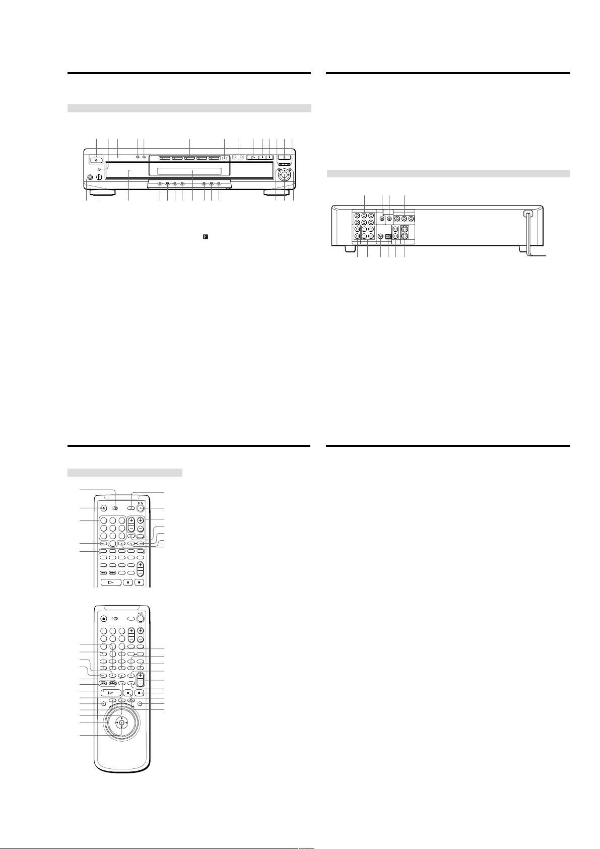
Index to Parts and Controls
Refer to the pages indicated in parentheses for details.
Front Panel
qk wsqjqhqg ql w; wa
6
wd wh
wf wjwg wk
7 (remote sensor) (7)
Accepts the remote control signals.
8 ./>PREV/NEXT (previous/next) buttons (17)
Press to go to the next chapter or track, or to go back
to the previous chapter or track.
9 H (play) button (16)
Plays a disc.
q; X (pause) button (17)
Pauses playing a disc.
qa x (stop) button (17, 19)
Stops playing a disc.
qs EXCHANGE button (22)
Press to change discs during playback.
qd AOPEN/CLOSE button (16)
Opens or closes the disc tray.
qf DISC SKIP button (16, 22)
Press to turn the disc tray to place other discs.
qg PHONES connector (16)
Connect the headphones to this connector.
qh PHONES LEVEL control (16)
Adjusts the headphone volume.
qj Disc tray (16)
Place the discs on the tray.
qk SHUFFLE button (48)
Displays the “SHUFFLE” display on the TV screen.
ql REPEAT button (49)
Displays the “REPEAT” display on the TV screen.
w; 1/ALL button (45)
Selects 1 DISC or ALL
15432897 0 qa qs qd qf
1 ! (power) button and indicator (16)
Disconnects the power of the player or places the
player in standby mode.
2 VIRTUAL SURROUND HEADPHONES button and
indicator (41)
Press to turn on the VIRTUAL SURROUND
HEADPHONES function.
The indicator lights up when it is on.
3 MULTICHANNEL indicator
Lights up when:
– playing back a Dolby Digital soundtrack on the
DVD
– playing back a DTS soundtrack on the DVD
– the disc is not inserted
4 DVE (Digital Video Enhancer) button and indicator
(52)
Press to select a Digital Video Enhancer level.
The indicator lights up for every selected item except
“OFF.”
5 VIRTUAL 3D SURROUND button and indicator (41)
Press to select the desired “VIRTUAL 3D
SURROUND” item.
The indicator lights up for every selected item except
“OFF.”
6 DISC SELECT 1 – 5 buttons and indicators (18)
Selects a disc. The indicator lights up in green when a
disc is being played or is loaded, and lights up in
amber if the disc is waiting to be loaded. The
indicator does not light up when the loaded tray is
empty or if the disc cannot be played.
DISCS play mode.
wa LOAD button (25)
Reads the information of the discs loaded in sequence.
ws Front Panel Display (23)
Indicates the playing time, etc.
wd TITLE button (20)
Displays the title menu on the TV screen.
wf DVD MENU button (21)
Displays the DVD menu on the TV screen.
Rear Panel
3241
5.1CH OUTPUT
MEGA
COMPONENT VIDEO OUT
S-LINK
CENTER
CONTROL
WOOFER
1
2
CONTROL S
IN
PCM/DTS/
DOLBY DIGITAL
DIGITAL OUT
PB/B-Y PR/R-YY
121
2
OPTICALCOAXIAL
VIDEO
S VIDEO
OUT
OUT
L
FRONT REAR
R
L
R
AUDIO IN
RL
AUDIO OUT
587690
1 5.1CH OUTPUT connectors (13)
Connect to a receiver (amplifier) having 5.1 channel
input connectors.
2 S-LINK connector (8)
Connect to the S-link connector on an external
component.
3 MEGA CONTROL connector (72)
Connect to the control connector on a Sony CD
changer of 5/50/200/300 discs.
4 COMPONENT VIDEO OUT connectors (9)
Connects to a monitor or projector having component
video input connectors (Y, P
conform to output signals from the player.
5 AUDIO IN (L, R) connectors (72)
Connect to the audio output on a Sony CD changer of
5/50/200/300 discs.
B
/B-Y, PR/R-Y) that
wg ORETURN button (22, 29)
Press to return to the previously selected screen, etc.
wh MEGA CONTROL button and indicator (72)
Press to control the connected CD changer.
wj </M/m/,/ENTER button
Selects and executes the items or settings.
wk DISPLAY button (28)
Displays the Control Menu display on the TV screen
to set or adjust the Contr
6 AUDIO OUT R (right)/L (left) 1/2 connectors (8, 10)
Connect to the audio input connector on your TV or
receiver (amplifier).
7 DIGITAL OUT COAXIAL connector (10)
Connect to an audio component using a coaxial digital
connecting cord.
8 DIGITAL OUT OPTICAL connector (10)
Connect to an audio component using an optical
digital connecting cord. Take off the cap.
9 VIDEO OUT 1/2 connectors (8)
Connect to the video input connector on your TV or
monitor.
q; S VIDEO OUT 1/2 connectors (8, 10)
Connect to the S video input connector on your TV or
monitor.
ol Menu items.
82
Index to Parts and Contr
Remote
1
2
1
2
3
4
5
qd
qf
qg
qh
qj
qk
ql
w;
wa
ws
wd
wf
wg
3
4
5
6
7
8
9
0
1
2
3
4
5
6
7
8
9
0
83
ols
1 TV/DVD switch (70)
Selects to control the player or the TV with the remote.
2 ZOPEN/CLOSE button (17)
6
7
8
9
0
qa
qs
wh
wj
wk
wl
e;
ea
es
ed
ef
eg
Opens or closes the disc tray.
3 Number buttons
Selects the items or settings.
4 CLEAR button (47 through 50)
Press to return to continuous play, etc.
5 DISC 1 – 5 buttons (17)
Selects a disc.
6 DISC EXPLORER button (25)
Displays the disc information such as jacket picture
and disc memo.
7 @/1 (on/standby) button (16)
Press to turn on the player or place it in standby mode
after power is connected by pressing ! on the player.
8 TV (television) operation buttons (71)
Controls TVs.
9 MEGA CTL (control) button (72)
Press to control the connected CD changer.
q; TIME/TEXT button (23)
Displays the playing time of the disc, etc., on the front
panel display.
qa INPUT button (35)
Press when labeling a disc.
qs ENTER button
Executes the items or settings.
qd PROGRAM button (47)
Displays the “PROGRAM” display on the TV screen.
qf SHUFFLE button (48)
Displays the “SHUFFLE” display on the TV screen.
qg ANGLE button (38)
Changes the angles when playing a DVD.
qh AUDIO button (36)
Changes the sound while playing a DVD or VIDEO
CD.
qj SUBTITLE button (37)
Changes the subtitles when playing a DVD.
qk ./>PREV/NEXT (previous/next) buttons (17)
Press to go to the next chapter or track, or to go back
to the previous chapter or track.
ql HPLAY button (16)
Plays a disc.
w; PICTURE MEMORY button (61)
Press to store a picture in memory.
wa DISPLAY button (28)
Displays the Control Menu display on the TV screen
to set or adjust the Control Menu items.
ws TITLE button (20)
Displays the title menu on the TV screen.
wd DVD MENU button (21)
Displays the DVD menu on the TV screen.
wf Click shuttle (18)
Changes the playback speed.
wg </M/m/,/ENTER buttons
Selects and executes the items or settings.
wh REPEAT button (49)
Displays the “REPEAT” display on the TV screen.
wj 1/ALL DISCS button (45)
Selects 1 DISC or ALL DISCS play mode.
wk DVE (Digital Video Enhancer) button (52)
Press to select the Digital Video Enhancer level.
wl LOAD button (25)
Reads the information of the discs loaded in sequence.
e; AV VOL button (71)
Change the sound volume of the AV receivers
(amplifiers).
ea BOOKMARK button (54)
Press to set a bookmark.
es xSTOP button (17, 19)
Stops playing a disc.
ed XPAUSE button (17)
Pauses playing a disc.
ef JOG button and indicator (18)
Press to play a disc frame by frame.
eg ORETURN button (22, 29)
Press to return to the previously selected scr
een, etc.
84
1-19 E
1-19
85
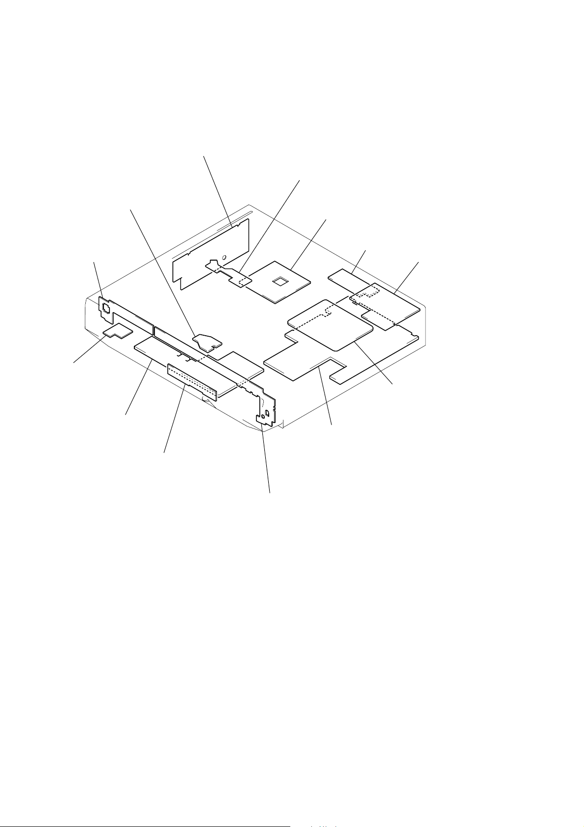
2-16. CIRCUIT BOARDS LOCATION
POWER BLOCK
(MPW1311) (C670D: E, Australian/C675D)
(MPW1240) (C660/C670D: US, Canadian)
(SWITCHING REGULATOR)
LM-61
(LOADING MOTOR)
FR-170
(FUNCTION SWITCH)
SE-110
(SENSOR)
TK-57
(RF/SERVO)
CV-33
(VIDEO OUT)
CH-97
(C670D/C675D)
(AUDIO OUT/LPF)
HP-128
(C670D/C675D)
(HEADPHONE)
FC-73
(IF CON)
SW-338
(FUNCTION SWITCH)
AI-18
AUDIO, VIDEO BUFFER, D/A
()
CONVERTER, DRIVE
FL-113
(FUNCTION SWITCH)
MB-87
(SIGNAL PROCESS)
2-6 E
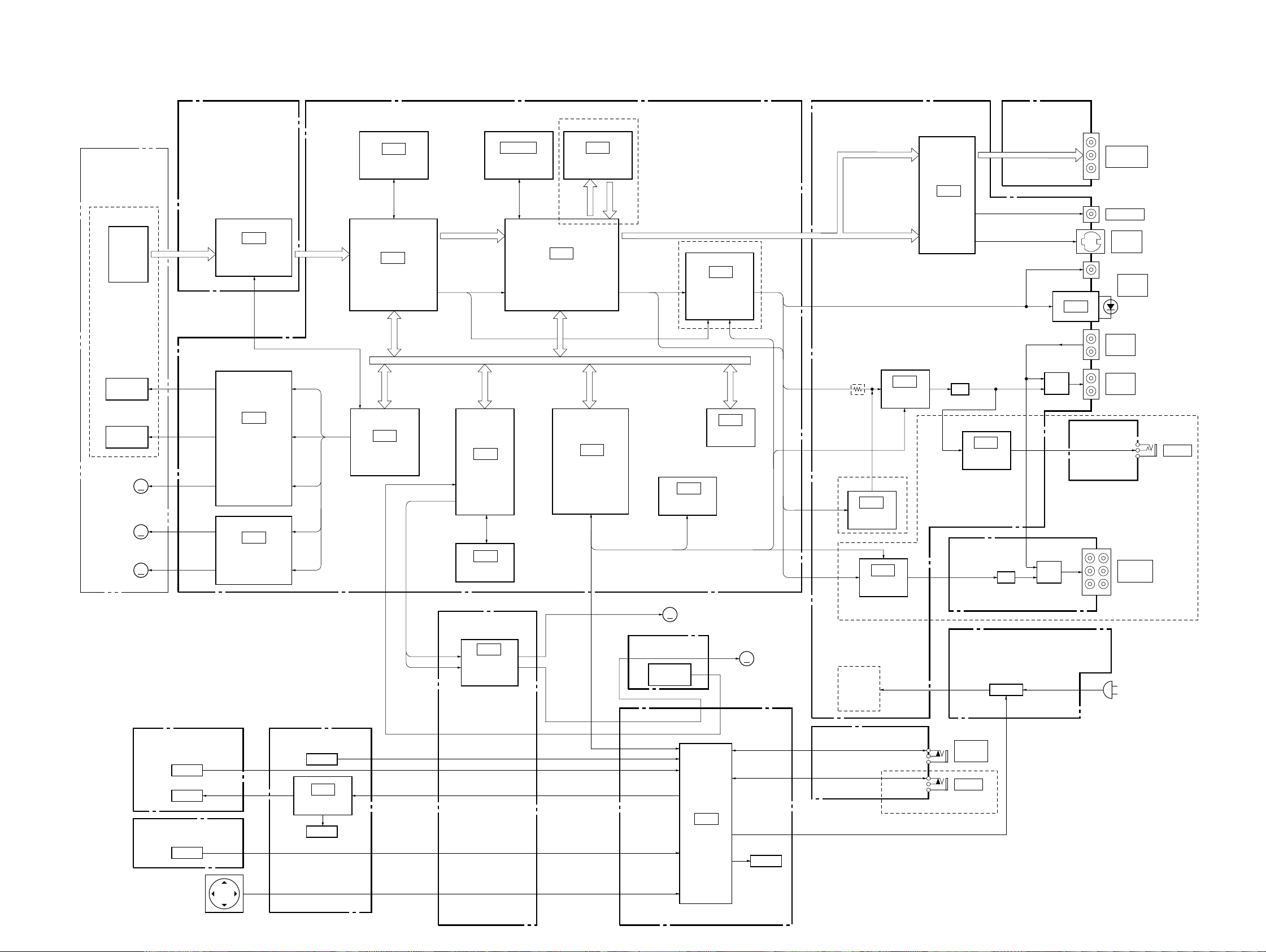
3-1. OVERALL BLOCK DIAGRAM
DVP-C660/C670D/C675D
SECTION 3
BLOCK DIAGRAMS
BASE UNIT
KHM-220AAA
OPTICAL DEVICE
DVD/CD
FOCUS
TRACKING
TILT
MOTOR
SPINDLE
MOTOR
SLED
MOTOR
PD IC
COIL
COIL
TK-57 BOARD
(SEE PAGE 4-11)
RF
IC001
DVD/CD RF AMP
IC401
FOCUS/TRACKING
COIL
DRIVE,
TILT MOTOR
DRIVE
MM
MM
MM
IC402
SPINDLE/SLED
MOTOR DRIVE
MB-87 BOARD
(SEE PAGE 4-19 to 4-38)
DVD/CD RF
IC303
16M DRAM
IC302
ARP
IC404
SERVO
DSP
SD0 – 7
CD DOUT, CD DATA,
CD BCK, CD LRCK
CD DOUT
PARALLEL BUS
IC803
FGA-C
IC802
NAND
FLASH
AI-18 BOARD (2/2)
(SEE PAGE 4-49)
IC902
TURN TABLE/
LOADING
MOTOR DRIVE
C670D/C675D
IC504, 505 IC601
16M SDRAM VGA
PDO0 – 7
IC502
AV
DECODER
IC102
SYSTEM
CONTROL
PDI0 – 7
SERIAL BUS
SPDIF, ACH12,
ACH34, ACH56,
BCK, LRCK
SE-110 BOARD
(SEE PAGE 4-14)
SENSOR
(DISC/TABLE)
MM
IC101
EEPROM
M201
LOADING
MOTOR
C670D/C675D
IC701
AUDIO
DSP
IC104
FLASH
MM
M951
TURN TABLE
MOTOR
AI-18 BOARD (1/2)
(SEE PAGE 4-41 to 4-48)
VIDEO Y,
VIDEO B – Y,
VIDEO R –Y
VIDEO V,
VIDEO Y,
VIDEO C
SPDIF
C670D/C675D
IC702
VES
DSP
IC802
AUDIO
DAC
EVER +5V
SW +5V
SW +3.3V
SW +11V
SW –11V
C660
IC703
AUDIO
DAC
IC603
VIDEO
BUFFER
LPF
HEADPHONE
CH-97 BOARD
(SEE PAGE 4-57)
MPW1240 BOARD
(SEE PAGE 4-73)
MPW1311 BOARD
(SEE PAGE 4-77)
CV-33 BOARD (1/2)
(SEE PAGE 4-52)
IC706
AMP
LPF
SW REG
IC804
RY701
HP-128 BOARD
(SEE PAGE 4-54)
RY401
: C660/C670D: US, CND
: C670D: AUS, E/C675D
COMPONENT
VIDEO OUT
VIDEO OUT
S VIDEO
OUT
DIGITAL
OUT
AUDIO
IN
AUDIO
OUT
5.1 CH
OUTPUT
AC IN
PHONES
C670D/C675D
05
•Abbreviation
CND: Canadian model
AUS: Australian model
FR-170 BOARD
(SEE PAGE 4-70)
SWITCH
LED
SW-338 BOARD
(SEE PAGE 4-68)
SWITCH
CURSOR
UNIT
ENTER
FL-113 BOARD
(SEE PAGE 4-67)
SWITCH
IC101
LED
DRIVER
LED
CV-33 BOARD (2/2)
(SEE PAGE 4-52)
CONTROL
S LINK
C670D: US, CND/C675D
FC-73 BOARD
(SEE PAGE 4-61)
IC401
IF CON
P CON
ND401
3-1 3-2
MEGA
DVP-C660/C670D/C675D
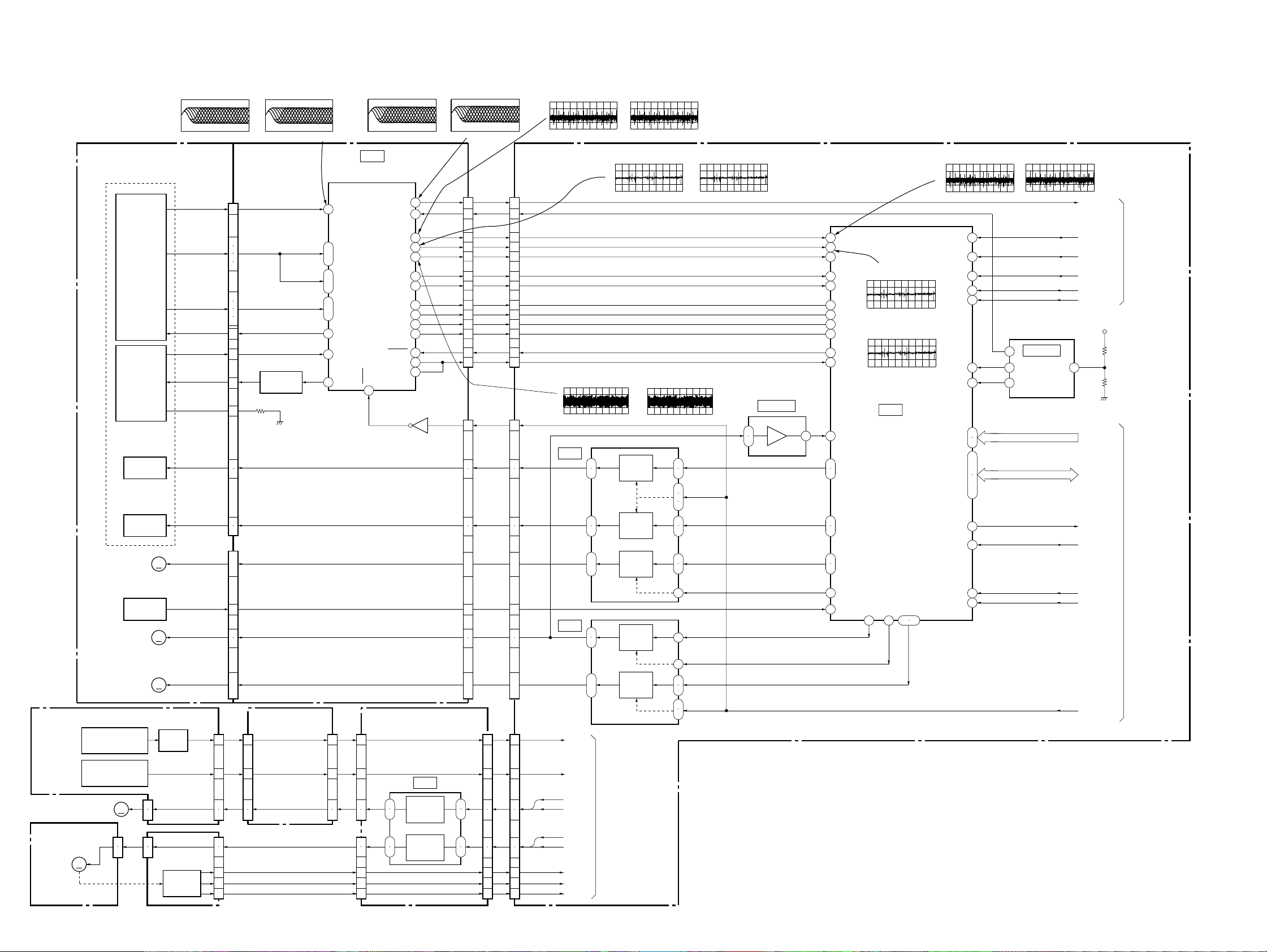
3-2. RF/SERVO BLOCK DIAGRAM
SE-110 BOARD
(SEE PAGE 4-14)
TURN TABLE
LM-61 BOARD
(SEE PAGE 4-50)
M201
LOADING
MM
MOTOR
BASE UNIT
KHM-220AAA
DVD/CD
PD IC
DVD/CD
LD MODULE
FOCUS
TRACKING
TILT
MOTOR
INLIMIT
SENSOR
SPINDLE
MOTOR
SLED
MOTOR
PH501
DISC PRESENCE
DETECTION SENSOR
PH502
TURN TABLE POSITION
DETECTION SENSOR
M951
B201
MM
LM
1
2
MOTOR
COIL
COIL
IC001 1 (DVD play)
200 mV/DIV 100 ns/DIV
MM
MM
MM
BUFFER
Q501
CN502
1
2
1
2
ROTARY
ENCODER
(LOADING)
IC001 1 (CD play)
500 mV/DIV 500 ns/DIV
536 mVp-p
TK-57 BOARD
(SEE PAGE 4-11)
CN001
RF
7
9
A – D
11
16
17
8
E – H
10
15
18
VC
13
PD
4
LD
2
VR
5
FCS
TRK
TIA, TIB
SLA, SLB
CN501 CN403
INLIM
SPM
19
20
21
22
CN002
10
ı
13
2
8
9
4
ı
7
FC-73 BOARD (1/2)
(SEE PAGE 4-61)
1
1
3
3
5
5
6
6
1
2
3
4
6
880 mVp-p
Q001
LD DRIVE
LM
S1
S2
S3
CN402
(1/2)
1
9
ı
12
5
ı
8
13
ı
16
17
19
20
15
12
11
13
IC001 tf (DVD play)
500 mV/DIV 100 ns/DIV
IC001
DVD/CD RF AMP
DIGITAL SERVO
RF IP
A – D
A2 – D2
E – H
VC
PD
LD
LDON
25
AI-18 BOARD (1/4)
(SEE PAGE 4-49)
15
12
11
13
CN908
1
2
3
4
6
1.5 Vp-p
SIGO
FE
TE
PI
MIRR
TZC
SCLK
SWD
SRD
FDCHG
DFT
HOLD2
14
16
11
13
54
33VCI
40
39
29
26
32
43
44
45
46SDEN
27
31
42
Q002
IC902
TURN TABLE
MOTOR
DRIVE
LOADING
MOTOR
DRIVE
IC001 tf (CD play)
500 mV/DIV 500 ns/DIV
1.5 Vp-p
MB-87 BOARD (1/6)
(SEE PAGE 4-27, 29, 35)
17
6
9
8
7
3
5
11
12
13
14
15
4
CN004 CN405
1
4
5
2
3
13
ı
16
6
11
12
7
ı
10
CN905
(1/3)
21
9
22
10
4
5
5
6
CN404CN003
17
6
9
8
7
3
5
11
12
13
14
15
4
1
4
5
2
3
13
ı
16
6
11
12
7
ı
10
CN801 (1/3)CN902 (2/2)
7
14
8
13
11
12
15
16
4
17
3
18
2
19
IC001 r; (DVD play)
100 mV/DIV 50 ms/DIV
180 mVp-p
IC001 el (DVD play)
500 mV/DIV 50 ms/DIV
IC001 wl (DVD play)
200 mV/DIV 500 ms/DIV
592 mVp-p
IC401
2
3
4
5
32
ı
35
IC402
2
3
32
ı
35
DSSW1
TSW1
TRMP
TRMM
CKMP
CKMM
CKSW1
CKSW2
LDSW1
CONTROL
(SEE PAGE 3-10)
IC001 r; (CD play)
500 mV/DIV 50 ms/DIV
860 mVp-p
1.3 Vp-p
IC001 wl (CD play)
200 mV/DIV 20 ms/DIV
448 mVp-p
FOCUS
COIL
DRIVE
TRACKING
COIL
DRIVE
TILT
MOTOR
DRIVE
SPINDLE
MOTOR
DRIVE
SLED
MOTOR
DRIVE
SYSTEM
IC001 el (CD play)
500 mV/DIV 200 ms/DIV
1.7 Vp-p
14
15
20
28
29
12
13
22
25
30
15
29
22
25
20
30
5
6
SSDFCT
SSDFCTI
IC403 (1/2)
TILT A1, B1
TILT MUTE1
SLDA1, B1
FE
TE
PI
SPDL1
SPCNT1
7 17
22
23
21
27
26
45
46
47
48
41
34
1
3
5
7
53
54
49
32
ADC1
ADC0
ADC2
IC404 wd (DVD play)
500 mV/DIV 50 ms/DIV
MIRR
TZC
GIO8
GIO7
GIO6
IC404 wd (CD play)
GIO5
500 mV/DIV 200 mV/DIV
GIO11
DFCTI
IC404
ADC6
PDM 2, 3
PDM 0, 1
GIO1, 2
GIO4
FGIN
SERVO DSP
PWM2
71 55
1.4 Vp-p
1.7 Vp-p
GIO0
72 73
IC404 ws (DVD play)
100 mV/DIV 50 ms/DIV
HA 0, 1
HD 0 – 7
PWM0, 1
ADC4
ADC5
FGREF
HWR
HRD
VRTA
HINT
HCS
CLKIN
RS
180 mVp-p
19
18
31
78
79
9
13VRBA
80
81
82
ı
84
86
ı
90
76
77
95
68
IC404 ws (CD play)
500 mV/DIV 50 ms/DIV
14
9 12
13
860 mVp-p
IC403 (2/2)
REFERENCE
VOLTAGE
GENERATOR
HA 0, 1
HD 8 – 15
RF+
(DVD/CD) RF
MDS0
MDP0
LOCK
WRH
RD
+3.3V
HA 0, 1
HD 8 – 15
SDSPINT
XSDSPCS
27MSDP
XRST
XDRVMUTE
SIGNAL PROCESSOR
(SEE PAGE 3-5)
SYSTEM CONTROL
(SEE PAGE 3-9, 10)
05
3-3 3-4
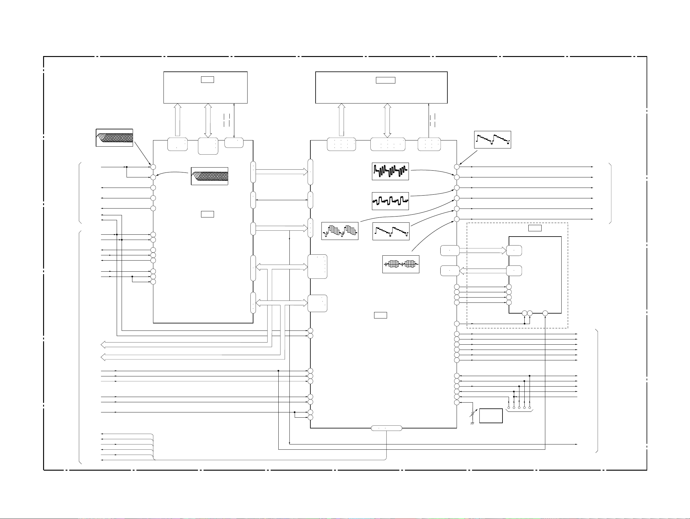
3-3. SIGNAL PROCESS BLOCK DIAGRAM
MB-87 BOARD (2/6)
(SEE PAGE 4-19 to 4-25)
IC303
16M DRAM
DVP-C660/C670D/C675D
IC504, 505
16M SDRAM
RF/SERVO
(SEE PAGE 3-4)
SYSTEM CONTROL
(SEE PAGE 3-9, 10)
IC302 qj (DVD play)
500 mV/DIV 100 ns/DIV
RF+
(DVD/CD) RF
MDSO
MDPO
LOCK
RD
WRH
WRH
RD
ARINT
XARPCS
ARPWT
ARPRST
33MARP
HA 0 – 21
HD 0 – 15
1.6 Vp-p
HA 0 – 21
HD 0 – 15
CAS, OE
MA 0 – 9
136 – 139
141 – 144
146 147
17
RFIN1
19
RFIN2
49
MDSO
52
MDPO
58
LOCK
60
XWR
61
XRD
83
XINT
84
XCS
86
XWAT
87
XRST
121
MCKI
123
SCKI
154 – 157
159 – 162
164 – 167
169 – 172
IC302 ql (CD play)
500 mV/DIV 200 ns/DIV
1.6 Vp-p
IC302
ARP
WE, RAS,
MD 0 – 15
148
150 – 152
RD
WRH
31
ı
34
36
ı
39
41
43
ı
46
22
23
25
26
192 193
195 – 198
200 – 203
205 – 208
210 – 213
215 – 218
2 – 5
7 – 10
232 – 235
237 – 240
220
221
97
98
SD 0 – 7
100
ı
105
91
93
ı
96
107
ı
110
73
ı
76
A 0 – 7 HA 0 – 7
79
ı
82
63
ı
68
HD 8 – 15
70
71
SDI 0 – 7 DTI 0 – 7
SDCK, XSHD,
XSRQ, XASK, SDEF
CD DATA, CD BCK,
CD LRCK, CD DOUT
CD DOUT
HD 0 – 15D 0 – 7
SDAD 0 – 11
124 125 127 128
130 131 133 134
136 137 139 140
IC502 i;
1.2 Vp-p (H)
HAD 0 – 21HA 0 – 21
HD 0 – 15
SDDT 0 – 15
157 – 160 162 – 165
167 168 170 171
173 174 176 177
IC502 yd
720 mVp-p (H)
IC502 yh
728 mVp-p (H)
IC502 uf
1.1 Vp-p (H)
IC502 uj
520 mVp-p (H)
IC502
AV DECODER
CS, WE,
CAS, RAS
CLK, CKE,
DQML, DQMU,
143 144 146
147 149 151
152 154 155
69
G OUT/Y
COMPOUT
Y OUT
C OUT
102 – 105
107 – 110
92 – 95
97 – 100
FLDO
HSYNCO
NRSDOUT
NRSENB
DICLKO
ACH12
ACH34
ACH56
LRCKO
BCKO
63
66
80
74
77
C670D/C675D
87
88
112
113
60
14
15
16
18
19
20
DO
R OUT/B – Y
B OUT/R – Y
PDO 0 – 7 PDO 0 – 7
PDI 0 – 7PDI 0 – 7
IC502 yl
1.0 Vp-p (H)
VIDEO G
VIDEO R
VIDEO B
VIDEO V
VIDEO Y
VIDEO C
27MVGA32
38 – 41
44 – 47
15 – 17
19 – 23
13
1
2
3
FLD
H SYNC
NRSDIN
SCS
IC601
VGA
YCIN 0 – 7
YCOUT 0 – 7
CK27
SCLK
5 8 11
MRST
ACH12
ACH34
ACH56
LRCK
BCK
SPDIF1
Y/G
CB/R
CR/B
VIDEO V
VIDEO Y
VIDEO C
VIDEO
(SEE PAGE 3-7)
231
XRST
512FSAVD
33MAVD
XAVDCS2
XAVDCS3
27MAVD
AVINT
AVWT
DACK0
DREQ0
DACK1
DREQ1
05
CD DOUT
12
29
190
191
180
182
RSTB
ACLK
CRPCLKI
HAD23
HAD22
CLKI
SCLKIN
223 224 226 – 229
TMS
TCK
TDO
TRST
VREFI
121
120
119
122
118TDI
84
RV501
VIDEO
LEVEL
ADJ
LAND
(FOR J TAG)
XRST
TMS
TCK
TDI32
TRST
X3VRST
CD DOUT
SYSTEM CONTROL
(SEE PAGE 3-9, 10)
3-5 3-6
DVP-C660/C670D/C675D
11
14
17
25
23
21
13
20
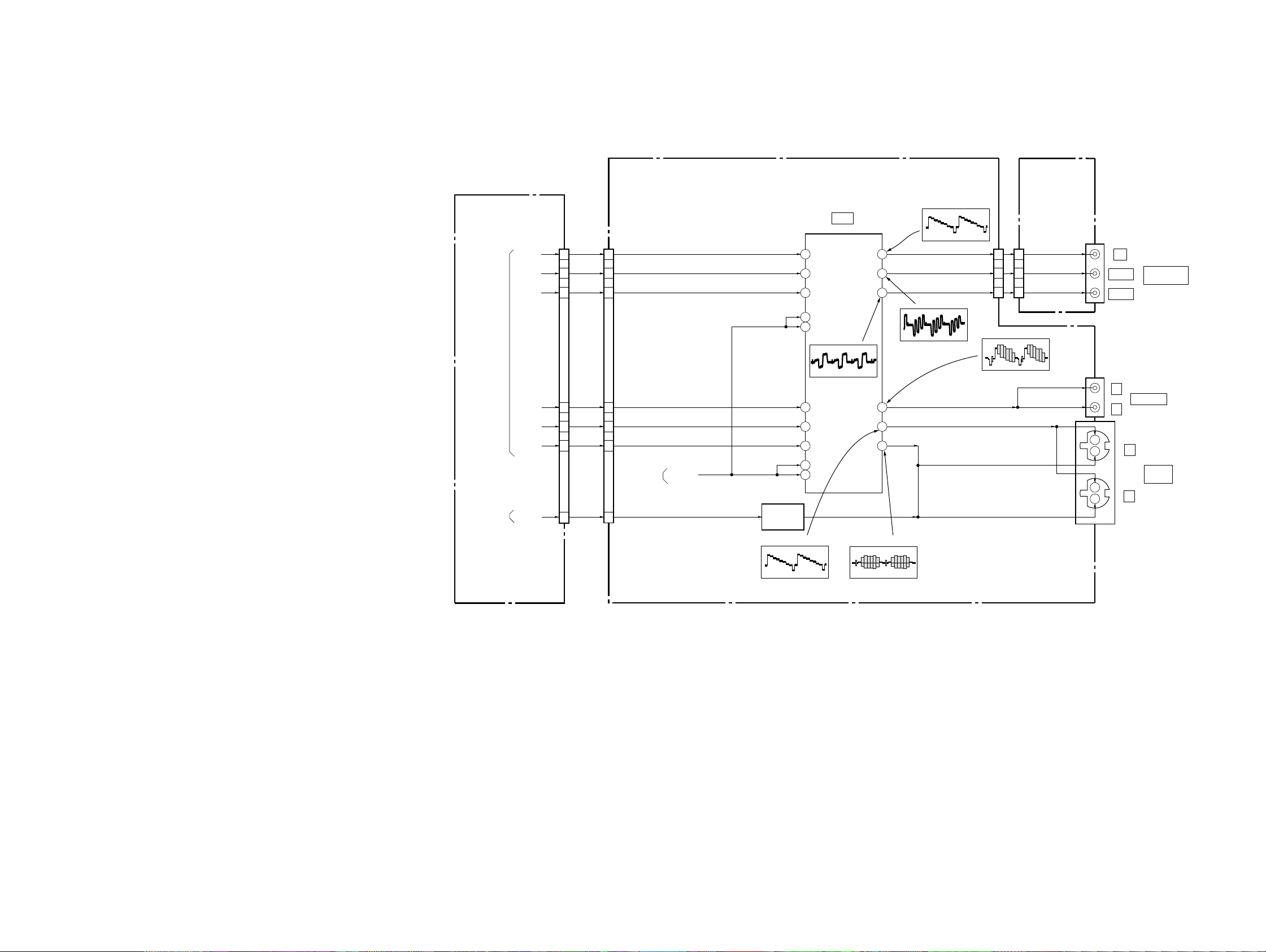
IC603
VIDEO BUFFER
1
7
4
35
Y
C
31
33
3
30
9
6
22
18
26
5
10
AI-18 BOARD (2/4)
(SEE PAGE 4-41, 49)
CV-33 BOARD (1/2)
(SEE PAGE 4-52)
MB-87 BOARD (3/6)
(SEE PAGE 4-21)
WIDE
SWITCH
Q601, 602
CN601
Y/G
CB/R
CR/B
VIDEO V
VIDEO Y
VIDEO C
WIDE
9
6
22
18
26
5
10
CN502
Y/G
CB/R
CR/B
VIDEO V
VIDEO Y
VIDEO C
WIDE
VMUTE
SIGNAL
PROCESSOR
(SEE PAGE 3-6)
05
SYSTEM
CONTROL
(SEE PAGE 3-9)
INTERFACE
CONTROL
(SEE PAGE 3-14)
Y IN
CB IN
CR IN
MUTE
MUTE
VIDEO IN
Y IN
C IN
MUTE
MUTE
Y OUT
CB OUT
CR OUT
VIDEO
OUT
Y OUT
C OUT
J301
J602
J601
Y
C
1
2
1
2
VIDEO OUT
PB/B-Y
COMPONENT
VIDEO OUT
Y
PR/R-Y
S VIDEO
OUT
7
9
5
7
9
5
CN301
(1/2)
CN906
(1/2)
IC603 wa
728 mVp-p (H)
IC603 wd
720 mVp-p (H)
IC603 wg
1.0 Vp-p (H)
IC603 ea
2.1 Vp-p (H)
IC603 ed
520 mVp-p (H)
IC603 eg
2.4 Vp-p (H)
3-4. VIDEO BLOCK DIAGRAM
3-7 3-8
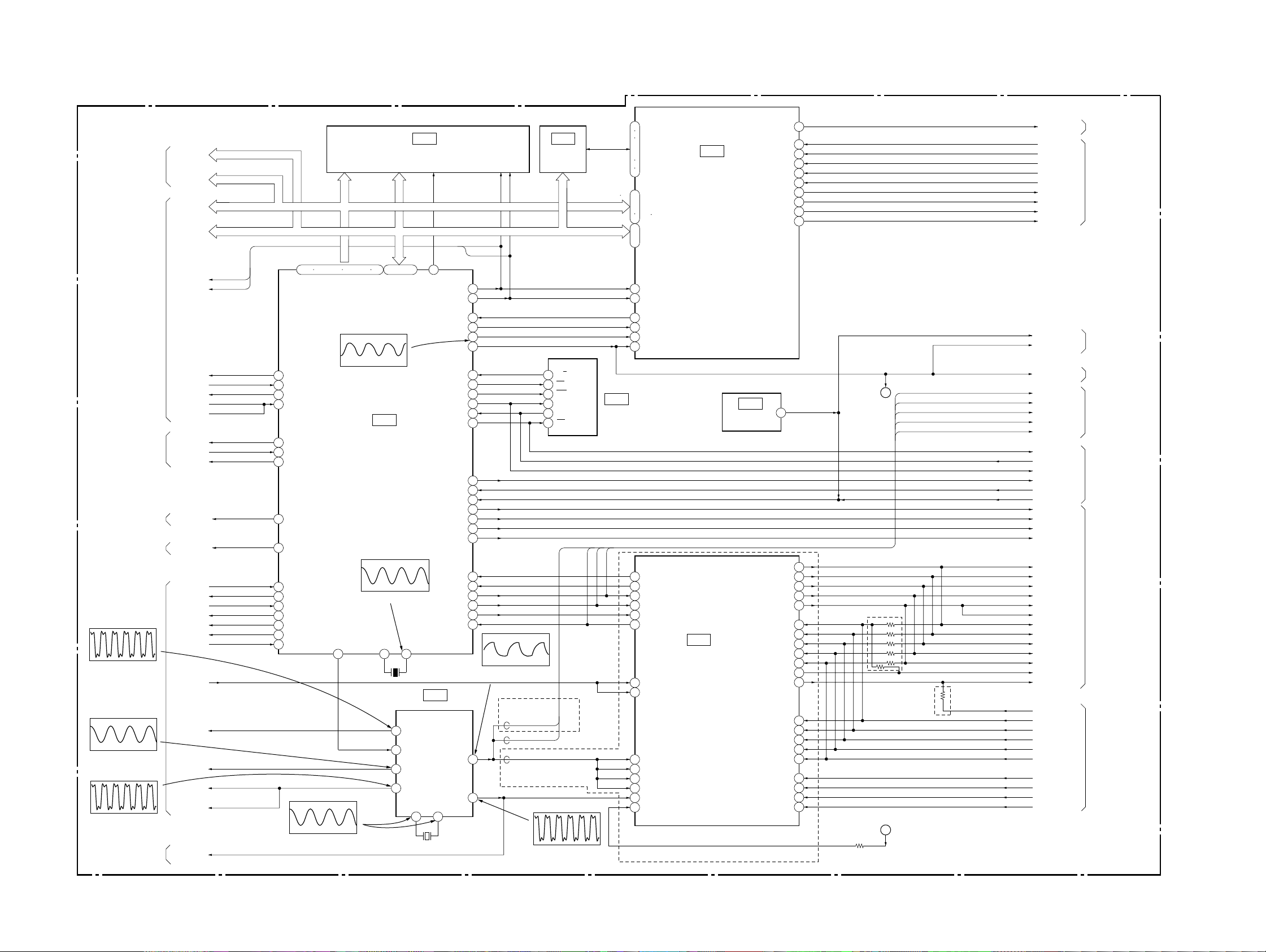
3-5. SYSTEM CONTROL BLOCK DIAGRAM
DVP-C660/C670D/C675D
MB-87 BOARD (4/6)
(SEE PAGE 4-31 to 4-37)
RF/SERVO
(SEE PAGE 3-4)
SIGNAL PROCESSOR
(SEE PAGE 3-5)
RF/SERVO
(SEE PAGE 3-4)
VIDEO
(SEE PAGE 3-7)
AUDIO
(SEE PAGE 3-11)
IC1054
5.2 Vp-p (27 MHz)
SIGNAL PROCESSOR
(SEE PAGE 3-5, 6)
IC105 qh
DVD: 4.3 Vp-p (29.5 MHz)
CD: 4.3 Vp-p (22.58 MHz)
IC105 qs
4.9 Vp-p (33.8688 MHz)
RF/SERVO
(SEE PAGE 3-4)
HD 8 – 15
HA 0, 1
HA 0 – 21
HD 0 – 15
WRH
ARPRST
ARINT
XARPCS
ARPWT
AVWT
XDRV MUTE
SDSPINT
XSDSPCS
WIDE
DREQ0
DACK0
DREQ1
DACK1
XAVDCS2
XAVDCS3
AVINT
CD DOUT
27MAVD
512FSAVD
33MARP
33MAVD
27MSDP
TEST, CLE,
ALE, XWE,
IC104 IC802
NAND
FLASH
R/B
1
CS
3
WC
8
DI
5
DO
6
SK
4
512FS39
27M39
IC105 wf
4.9 Vp-p (27.2 MHz)
85 – 100
X1
4
23
16
12
X102
27MHz
HD0 – 15 HD0 – 15
X0
X101
12.5MHz
27M2
44.1/48k
512FS1
33M
IN OUT
8 9
FLASH
65
CSOX
IC105
PLL
HA 0 – 21
HD 0 – 15
RD
WRH
INT2
CS5X
CPUCK
XRST
INT3
ECS
EWC
SO0
SI0
SCO
IFCS
INT4
FRRST IN
AURST
DACCS1
DACCS0
MAMUTE
CKSW2
CLAPBSY
SC1
SO1
KCS/39CS
SI1
512FS2
27M3
RD
WRH
82
83
27
70
71
16
28
49
48
35
33
36
45
29
74
51
60
59
62
30
31
39
38
50
37
DVD: 3.4 Vp-p (29.5 MHz)
CD: 3.4 Vp-p (22.58 MHz)
15
24
FGAINT
XFGACS
CPUCK
XRST
XIFCS
IFBSY
XFRRST
AURST
6CH/VES CS
2CH CS
MAMUTE
39INT
CMDREQ
SC1
SO1
KCS/39CS
SI1
IC105 qg
C670D/C675D
512FS6CH
512FS2CH/VES
HD 8 – 15
HA 0, 1
HA 0 – 21
HD 0 – 15
HA0 – 21 HA1 – 21
RD
FS
1 – 5 102 – 109 111 – 118 120
ARPRST
22
INT1
26
CS4X
69
XWAIT
79
23
DRV MUTE
INT7
32
CS6
18
WIDE
63
DACMUTE/FS
8
DREQ0
43
DACK0
44
DREQ1
46
DACK1
47
CS2X
67
CS3X
68
INTO
25
IC105 8,9
2.5 Vp-p (27 MHz)
IC102 ua
4 Vp-p (25.3 MHz)
CONTROL
2.4 Vp-p (12.5 MHz)
44.1/48k
61
44.1/48k
IC102
SYSTEM
IC102 tf
53 54
XWP, XCE,
XRE, R/B
HD8 – 15
HD8 – 11
SI1
SO1
HA0 – 4 19
IC101
EEPROM
SC0
SI0
SO0
SC1
18
23
25
ı
28
30
31
3
SHA0
ı
7
SHA4
9
SHA19
19
ı
22
XRD
13
XHWR
11
64
IRQ
XCS5
16
CPUCK
2
XRST
10
CMD ACKNO
107
108
CMD REQNO
SH CLKI
115
SH SII
117
SH CSNI
118
SH SOO
119
DSP1DII
10
DSP2DII
32
DSP1DIACKI
8
DSP2DIACKI
34
DSP2ACKI
67
DSPIACKI
149
SCLKI
22
RESET NI
6
MEGA MUTE
DSSW1
TSW1
CKSW1
CKSW2
LDSW1
TRMM
TRMP
CKMM
CKMP
X3VRST
XRST
XRST
512 FS 6CH
512 FS 2CH/VES
SC1
SO1
SI1
SC0
SI0
SO0
XIFCS
XIFBUSY
XFRRST
AURST
6CH/VES CS
2CH CS
MA MUTE
6CH FRONT
6CH REAR
KCS/6CH C/SW
6CH LRCK
6CH BCK
BCK
6CH FRONT
6CH REAR
6CH C/SW
LRCK
BCK
2CH DATA
SPDIF
SPDIF1
ACH12
ACH34
ACH56
LRCK
BCK
TDI32
TMS
TCK
TRST
DSSW1
TSW1
CKSW1
CKSW2
LDSW1
TRMM
TRMP
CKMM
CKMP
4
DSP2 DO
TDI
TMS
TCK
TRST
55
45
46
57
58
59
41
42
43
44
XRST
512FS6CH
A
512FS2CH/VES
SC1
SO1
SI1
SC0
SI0
SO0
XIFCS
XIFBUSY
XFRRST
AURST
6CH/VES CS
2CH CS
MA MUTE
48
49
50
42
43
56
57
58
55
69
51
45
160
159
158
161
147
140
141
143
142
6CH FRONT
6CH REAR
KCS/6CH C/SW
LRCK
BCK
C660
6CH FRONT
6CH REAR
6CH C/SW
LRCK
BCK
2CH DATA
SPDIF
C660
MEGA MUTE
IC803
FGA-C
ı
D0
ı
D3
IC103
RESET
DSP2 CH12O
DSP2 CH34O
DSP2 CH56O
DSP2 LRCKO
DSP2 BCKO
DSP2 CH12I
IC701
AUDIO
DSP
DSP2 CH34I
DSP2 CH56I
DSP2 LRCKI
DSP2 BCKI
DSP2 CH78O
DSP1 CH12I
DSP1 CH34I
DSP1 CH56I
DSP1 LRCKI
DSP1 BCKI
A
C670D/C675D
AUDIO
(SEE PAGE 3-11)
RF/SERVO
(SEE PAGE 3-4)
SIGNAL PROCESSOR
(SEE PAGE 3-5)
RF/SERVO
(SEE PAGE 3-4)
AUDIO
(SEE PAGE 3-11)
INTERFACE
CONTROL
(SEE PAGE 3-13)
AUDIO
(SEE PAGE 3-11)
SIGNAL PROCESSOR
(SEE PAGE 3-6)
05
3-9 3-10
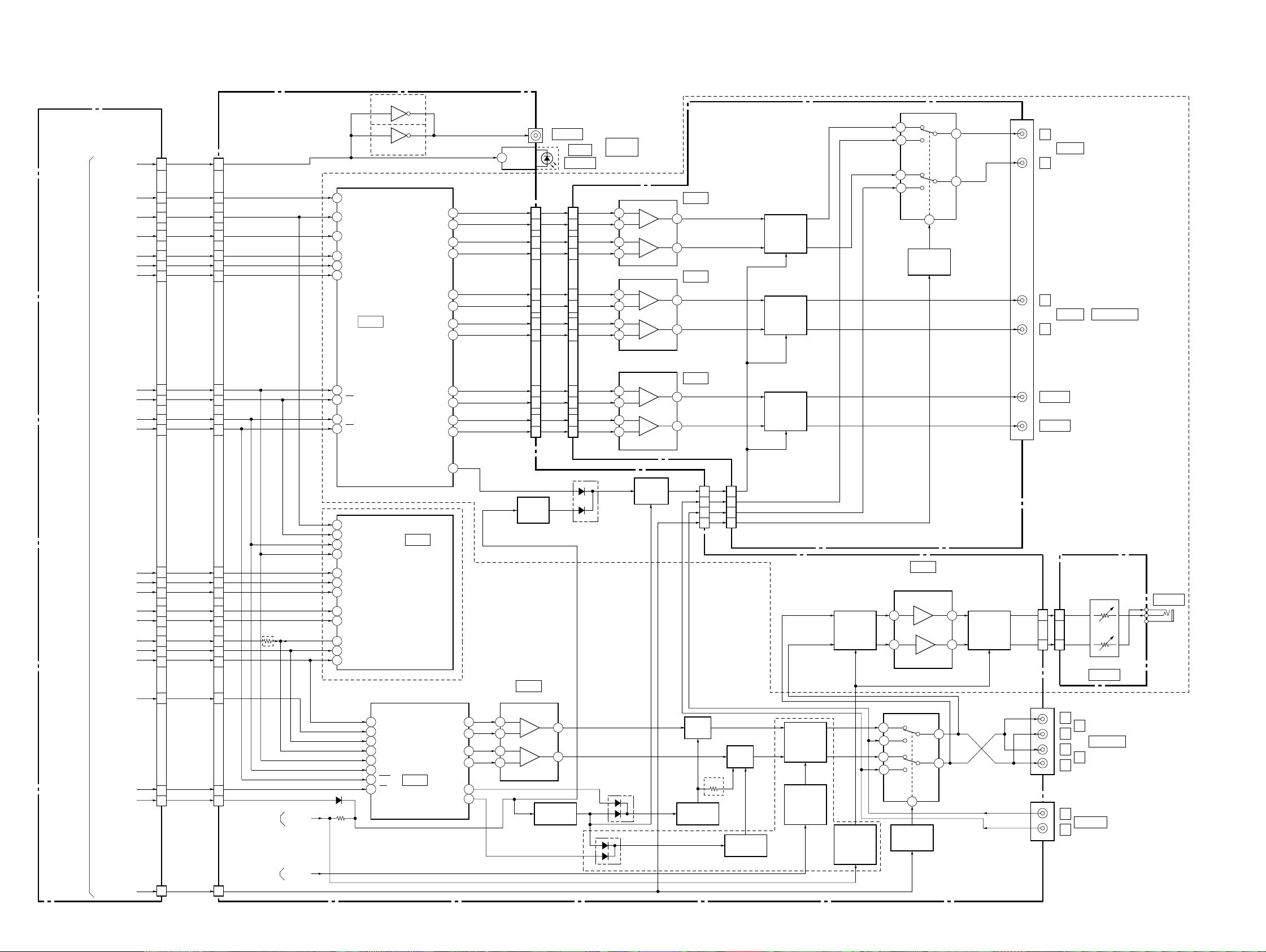
DVP-C660/C670D/C675D
3-6. AUDIO BLOCK DIAGRAM
MB-87 BOARD (5/6)
(SEE PAGE 4-35, 37)
6CH FRONT
6CH REAR
KCS/6CH C/SW
6CH LRCK
512FS6CH
6CH/VES CS
SPDIF
6CH BCK
SO1
SC1
AURST
CN702
1
6CH FRONT
17
6CH REAR
19
KCS/6CH C/SW
21
6CH LRCK
23
6CH BCK
9
512/FS6CH
13
6
6CH/VES CS
25
5
27
SPDIF
SO1
SC1
AURST
AI-18 BOARD (3/4)
(SEE PAGE 4-43 to 4-50)
CN701
1
17
19
21
23
9
13
6
25
5
27
13
14
15
16
9
10
19
20
18
8
SDTI1
SDTI2
SDTI3
LRCK
BCKI
MCLK
IC802
AUDIO
CONVERTER
CDTI
CS
CCLK
PD
Q805 – 807
C670D/C675D
D/A
Q806
C660
C670D/C675D
LOUT 1+
LOUT 1–
ROUT 1+
ROUT 1–
LOUT 2+
LOUT 2–
ROUT 2+
ROUT2–
LOUT 3+
LOUT 3–
ROUT 3+
ROUT 3–
CH-97 BOARD
J801
COAXIAL
1
D IN
2
1
44
43
42
41
40
39
38
37
36
35
CN802 CN402
23
21
19
17
15
14
11
9
7
5
3
1
IC804
OPTICAL
1
3
5
7
9
11
13
15
17
19
21
23
DIGITAL
OUT
3
2
5
6
3
2
5
6
3
2
5
6
(SEE PAGE 4-57)
IC401
LPF+6dB
1
7
IC402
LPF+12dB
1
7
IC403
LPF+12dB, +16dB
1
7
MUTE
Q405, 406
MUTE
Q403, 404
MUTE
Q401, 402
RY401
5
7
4
2
RELAY
DRIVE
Q407
6
3
8
J401
L
R
L
R
CENTER
WOOFER
FRONT
REAR
5.1CH OUT PUT
SYSTEM
CONTROL
(SEE PAGE 3-10)
05
6CH FRONT
6CH REAR
6CH C/SW
BCK
SI1
2CH DATA
512FS2H/VES
LRCK
BCK
2CH CS
MA MUTE
MEGA MUTE
16
14
12
10
8
28
512FS2H/VES
20
24
26
4
3
CN801
(2/3)
20 1
6CH FRONT
6CH REAR
6CH C/SW
BCK
SI1
2CH DATA
LRCK
BCK
2CH CS
MA MUTE
16
14
12
10
8
28
20
24
26
4
3
CN905 (2/3)
C670D/C675D
INTERFACE
CONTROL
(SEE PAGE 3-14)
SYSTEM
CONTROL
(SEE PAGE 3-9)
A MUTE
3
DZFL2
MUTE
DRIVE
MUTE
DRIVE
48
XRST
11 XCS
14
SCK
13
SI
6
SDIO
7
SDI1
8
SDI2
9
BCKI
17
SO
37
SDO0
3
MCLK
5
LRCKI
C660
5
4
6
3
9
8
1
10
FS
LRCK
SCLK
MCLK
SDATA
SDA
SCL
RST
CS
IC702
VES DSP
IC703
AUDIO
D/A
CONVERTER
AOUT A+
AOUT A–
AOUT B+
AOUT B–
BMUTE C
AMUTE C
18
19
15
14
13
20
Q801
IC704
AMP/LPF
3
2
5
6
1
7
MUTE DRIVE
Q701
Q802, 803
CN801
7
4
6
2
MUTE
Q708
MUTE DRIVE
Q702, 704
C660
7
4
6
2
CN401
MUTE
Q709
MUTE DRIVE
Q703, 705
C670D/C675D
FILTER
CONT
Q711, 712
FILTER CONT
CONT
Q713
MUTE
Q706, 707
MUTE
DRIVE
Q716 – 718
5
7
4
2
3
RELAY
DRIVE
IC706
HEADPHONE
AMP
RY701
8
Q710
HP-128 BOARD
(SEE PAGE 4-54)
J501
CN702
1
MUTE
Q714, 715
75
J701
6
3
J702
CN501
131
3
RV501
LEVEL
L
1
R
AUDIO OUT
L
2
R
R
AUDIO IN
L
PHONES
3-11 3-12
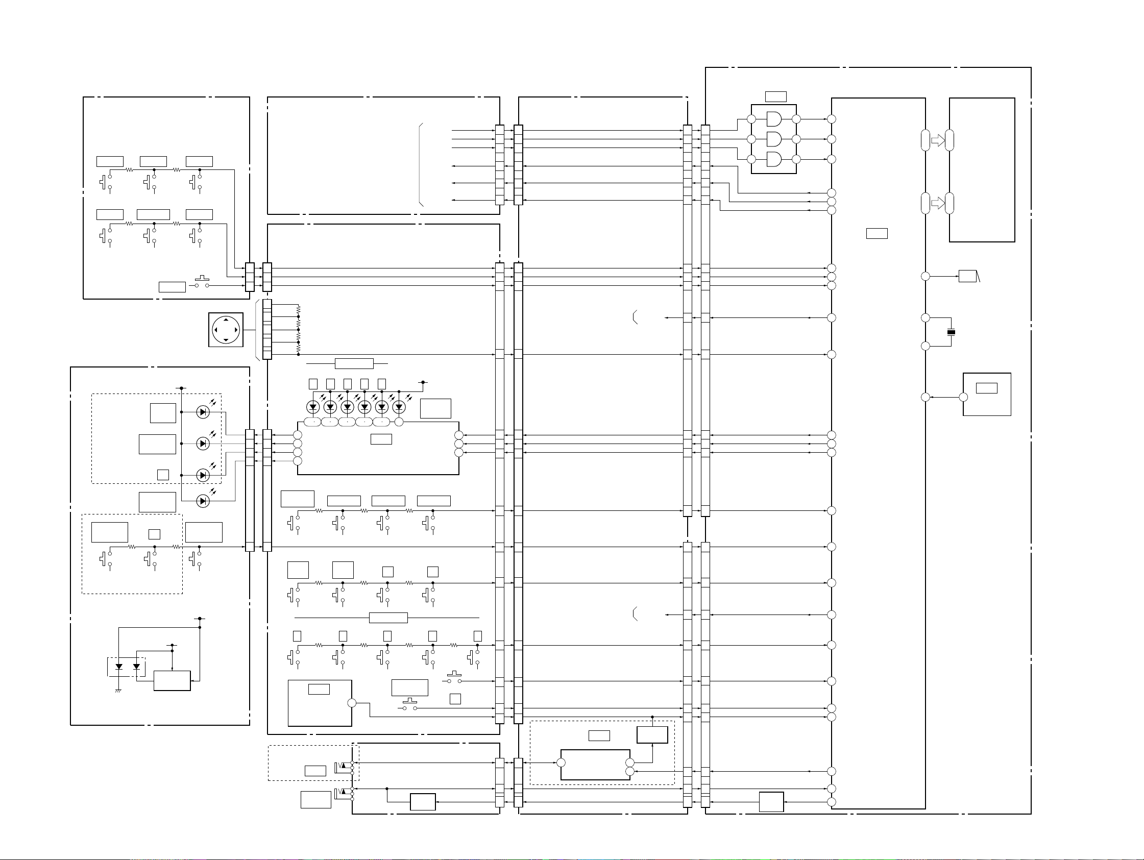
3-7. INTERFACE CONTROL BLOCK DIAGRAM
SW-338 BOARD
(SEE PAGE 4-68)
S307
SHUFFLE
S303
TITLE
FR-170 BOARD
(SEE PAGE 4-70)
C670D/C675D
S203 S201
VIRTUAL 3D
HEADPHONE
C670D/C675D
S306
REPEAT
S302
DVD MENU
DIGITAL
D203
VIRTUAL 3D
HEADPHONE
D201
VIRTUAL 3D
SURROUND
S202
R
D204
DOLBY
D202
2
R
2
S304
LOAD
LED +5V
S305
1/ALL
S301
RETURN
CURSOR UNIT
VIRTUAL 3D
SURROUND
CN301
ENTER
MB-87 BOARD (6/6)
(SEE PAGE 4-35)
FL-113 BOARD (SEE PAGE 4-67)
CN103
AD6
2
2
AD7
3
3
LOAD
1
1
RIGHT
2
UP
4
ENTER
5
DOWN
7
LEFT
6
CN104
CN101CN201
1
1
2
2
3
3
4
4
AD1
7
7
D102 D103 D104 D105 D106
17
LED (DD)
18
LED (3DHP)
19
LED (R2)
20
LED (3D)
S112
MEGA
CONTROL
S106
PREV
.
1 2 3 4 5
21 1 2 3 4 7 8 9 10 11
DISC SELECT
S113
EXCHANGE
S107
NEXT
>
SYSTEM
CONTROL
(SEE PAGE 3-10)
5
IC101
LED
DRIVE
S114
DISC SKIP
S109
X
LED +5V
CONTROL
DISPLAY
SC0
SO0
XIFCS
SI0
XIFBUSY
XFRRST
D101
MEGA
DATA
S115
S110
x
STB
CLK
CN801
CN102 CN903
14
13
12
(3/3)
9
12
8
13
6
15
7
14
5
16
4
17
CN905
14
6
15
5
16
4
13
7
17
3
18
2
19
1
12
8
3
17
5
15
AI-18 BOARD (4/4)
(SEE PAGE 4-49)
(3/3)
AUDIO
(SEE PAGE 3-11)
XIFBUSY
A MUTE
LED CLK
LED DATA
SC0
SO0
XIFCS
XFRRST
AD6
AD7
LOAD
AD5
LED CS
AD4
AD1
AD3
CN902
(2/2)
SI0
CN901
14
14
17
17
19
19
16
16
18
18
20
20
4
4
2
2
3
3
10
10
6
6
5
5
7
7
9
9
8
8
CN401
17
17
13
13
FC-73 BOARD (2/2)
(SEE PAGE 4-61)
CN402
(2/2)
4
1
12
IC403
DVP-C660/C670D/C675D
ND401
SCLK
6
3
11
70
72
76
71
69
8
80
79
78
11
1
65
66
67
2
5
3
SI
CS
SO
BUSY
FRRST
AN6
AN7
LOAD
A MUTE
AN5
LED CS
LED CLK
LED DATA
AN4
AN1
AN3
IC401
IF CON
SEG 20
ı
SEG 1
DIG 1
ı
DIG 14
BUZ
RST
45
47
ı
ı
64
66
FLUORESCENT
INDICATOR
TUBE
31
5
ı
ı
44
18
20
X1
14
X401
X0
15
10
4MHz
BZ401
BUZZER
IC402
4
RESET
05
• Abbreviation
CND: Canadian model
D207
(ON/STANDBY)
P DET
LED DRIVE
Q201, 202
SW 5V
S101 S102 S103 S104 S105
1 2 3 4 5
IC102
REMOTE
COMMANDER
RECEIVER
C670D: US, CND/C675D
J302
S LINK
J303
MEGA
CONTROL
DISC SELECT
OPEN/CLOSE
1
CV-33 BOARD (2/2)
(SEE PAGE 4-52)
S111
A
BUFFER
Q301
3-13 3-14
S108
G
SIRCS
CN301 (2/2)
S LINK
A1 IN
A1 OUT
VIDEO
(SEE PAGE 3-7)
4
16
6
14
7
13
1
19
C670D: US, CND/C675D
3
3
2
2
1
1
CN906 (2/2)
IC901
S LINK
I12
OUT 2
IN 2
76
V MUTE
OPEN/CLOSE
SIRCS
IR BUFFER
Q901, 902
STATUS
AD2
PLAY
V MUTE
4
4
15
15
11
11
9
9
19
19
2
2
1
1
3
3
BUFFER
Q403
12
AN2
4
PLAY
24
OPEN/CLOSE
25
IR
9
STATUS
275
A1 IN
22
A1 OUT
19
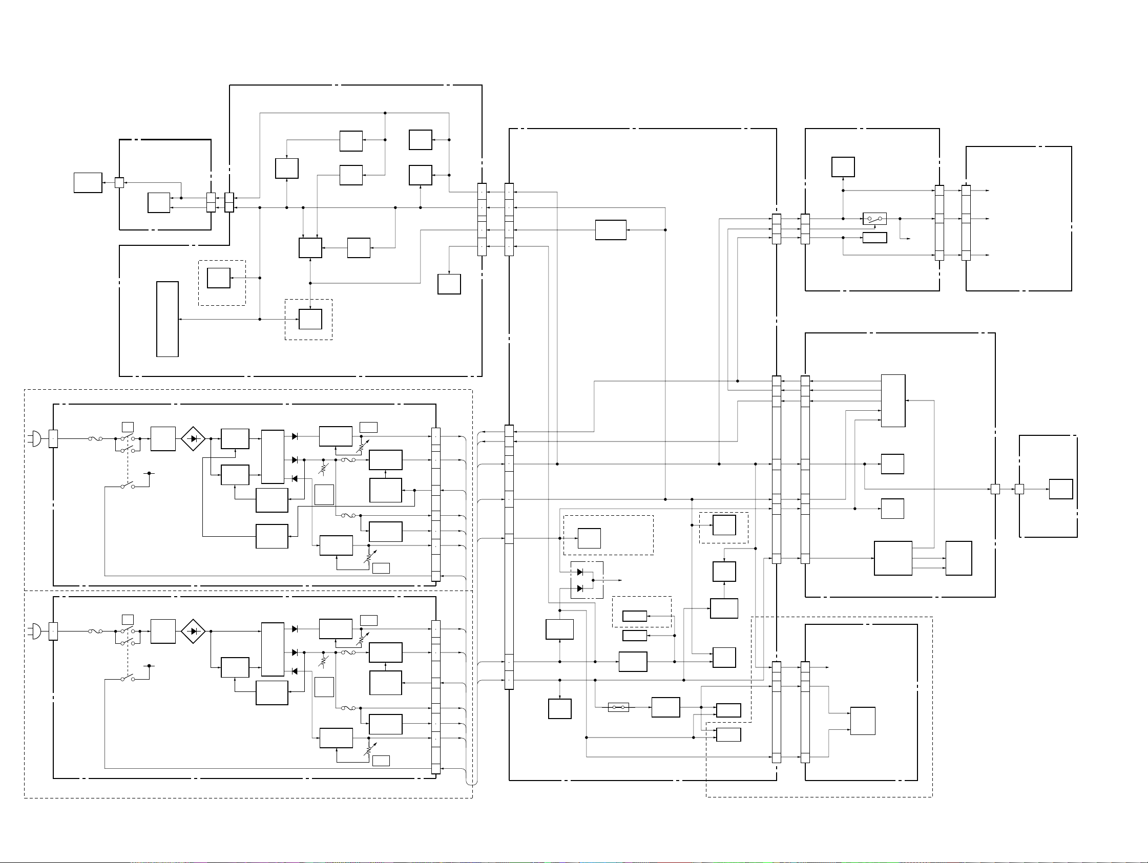
DVP-C660/C670D/C675D
3-8. POWER BLOCK DIAGRAM
MB-87 BOARD
(SEE PAGE 4-19 to 4-38)
C670D: AUS, E/C675D
MPW1311 BOARD
(SEE PAGE 4-77)
CN1
1
2
OPTICAL
DEVICE
IC301
Q101 – 104
+11V REG
VR301
EVER
+5V
Q401 – 404
–11V REG
REG
IC503
REG
P302
P301
IC506
REG
VR101
+11V
RV101
Q301, 304
+3.3V REG
Q303
POWER
CONTROL
Q201, 302
+5V REG
VR401
–11V
TK-57 BOARD
(SEE PAGE 4-11)
T1
PC1
PHOTO
COUPLER
PC2
PHOTO
COUPLER
IC302
IC502
IC701
C670D/C675D
CN001
14
IC001
IC101
IC102
IC103
IC104
IC105
IC303
IC403
IC504
IC506
IC802
SW1
!
F1
EVER+5V
L1, 2
LINE
FILTER
CN003
+5V
+3.3V
C670D/C675D
1
10
IC601
CN404
1
10
Q20, 71
SWITCH
Q1, 2
SWITCH
IC403
IC803
CN101
SW+11V
SW+3.3V
P CONT
EVER+5V
SW+5V
SW–11V
P DET
CN502
SW+5V
13
14
SW+3.3V
25
27
+1.8V
1
3
SW+11V
19
21
IC401
IC402
3
4
8
9
2
7
5
6
14
15
1
AI-18 BOARD
(SEE PAGE 4-41 to 4-50)
CN601
13
14
25
27
1
3
19
21
CN907
P DET
1
P CONT
2
SW+5V
5
6
SW+3.3V
8
9
EVER+5V
7
IC601
+1.8V REG
C670D: US, CND/C675D
IC901
MUTE V
IC702
IC603
C660
CN903
CN901
FL-113 BOARD
(SEE PAGE 4-67)
IC101
CN101 CN201
9
CN102
12
11
18
18
7
16
14
12
10
8
SW+5V
8
LED CNT
9
P DET
2
FC-73 BOARD
(SEE PAGE 4-61)
CN401
P DET
18
LED CNT
7
P CONT
16
SW+5V
14
SW+3.3V
12
EVER+5V
10
SW–11V
8
Q101, 102
IC102
CONVERTER
IC401
IC403
IC402
T401
Q401, 402
DC-DC
VEE
LED
+5V
5
8
FR-170 BOARD
(SEE PAGE 4-70)
9
5
8
ND401
CN403
SW+5V
LED+5V
P DET
2 2
SE-110 BOARD
(SEE PAGE 4-14)
CN501
SW+5V
PH501
PH502
MPW1240 BOARD
(SEE PAGE 4-73)
CN1
1
2
C660/C670D: US, CND
05
SW1
!
F1
EVER+5V
L1, 2
LINE
FILTER
Q1, 2
SWITCH
T1
PC1
PHOTO
COUPLER
Q101 – 104
+11V REG
VR301
EVER
+5V
Q401 – 404
–11V REG
P302
P301
VR101
+11V
RV101
Q301, 304
+3.3V REG
Q303
POWER
CONTROL
Q201, 302
+5V REG
VR401
–11V
CN101
SW+11V
SW+3.3V
P CONT
EVER+5V
SW+5V
SW–11V
P DET
3
4
8
9
2
7
5
6
14
15
1
14
15
3
4
SW+11V
SW–11V
IC803
+8V REG
IC902
C670D/C675D
IC802
IC804
IC701
+5V REG
PS903
A+5V
Q804
–8V REG
IC602
–5V REG
IC703
IC704
IC706
CN801
CH-97 BOARD
(SEE PAGE 4-57)
CN401
SW+5V
1
1
–8V
5
5
IC401
IC402
IC403
+8V
3
3
C670D/C675D
•Abbreviation
CND: Canadian model
AUS: Australian model
3-15 3-16 E

DVP-C660/C670D/C675D
SECTION 4
PRINTED WIRING BOARDS AND SCHEMATIC DIAGRAMS
THIS NOTE IS COMMON FOR PRINTED WIRING
BOARDS AND SCHEMATIC DIAGRAMS.
(In addition to this, the necessary note is printed
in each block.)
For printed wiring boards:
• X : indicates a lead wire mounted on the component
• x : indicates a lead wire mounted on the printed side.
•
• b : Pattern from the side which enables seeing.
(The other layers’ patterns are not indicated.)
Caution:
Pattern face side: Parts on the pattern face side seen from
(Side B) the pattern face are indicated.
Parts face side: Pa rts on the parts face side seen from
(Side A) the parts face are indicated.
a
side.
: Through hole.
For schematic Diagram:
• Caution when replacing chip parts.
New parts must be attached after removal of chip.
Be careful not to heat the minus side of tantalum capacitor,
because it is damaged by the heat.
• All resistors are in ohms, 1/
less otherwise specified.
kΩ : 1000Ω, M Ω : 1000kΩ.
• All capacitors are in µF unless otherwise noted. pF : µµF
50V or less are not indicated except for electrolytics and
tantalums.
• All variable and adjustable resistors hav e characteristic curve
B, unless otherwise noted.
• 2 : nonflammab le resistor.
• 5 : fusible resistor.
• C : panel designation.
f
•
• C : adjustment for repair .
• U : B+ Line.
• V : B– Line.
• Circled numbers refer to wa veforms.
• V oltages are dc betw een measurement point.
• Readings are taken with a color-bar signals on DVD reference disc and when playing CD reference disc.
• Readings are taken with a digital multimeter (DC 10MΩ).
• Voltage variations may be noted due to normal production
tolerances.
Note:
The components identified by mark 0 or dotted
line with mark 0 are critical for safety.
Replace only with part
number specified.
: internal component.
4
W (Chip resistors : 1/
Note:
Les composants identifiés par
une marque 0 sont critiques
pour la sécurité.
Ne les remplacer que par une
pièce portant le numéro
spécifié.
10
W) un-
When indicating parts by reference
number, please include the board
name.
4-1
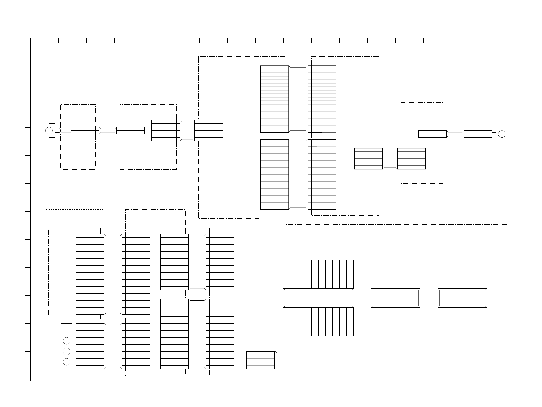
DVP-C660/C670D/C675D
4-1. FRAME SCHEMATIC DIAGRAM
FRAME (1) SCHEMATIC DIAGRAM
1
2 13 17
3 14
8
915
107
11
126 1654
A
CN901
19P
A1 IN
1
STATUS
2
A1 OUT
3
VMUTE
4
GND
B
C
M201
LOADING
MOTOR
M
D
LM-61
BOARD
Board IN HARNESS
6P
CN908
B201
1LM-
2LM+
1LM-
2LM+
1LM-
2LM+
3S1
4S2
5GND
6S3
1LM-
2LM+
3S1
AR-108LE-053
4S2
5 GND
6S3
ROTARY
ENCODER
(LOADING)
AI-18 BOARD (1/2)
E
F
LED-CNT
SW-11V
OPEN/CLOSE
EVER+5V
SW+3.3V
SW+5V
CN902
LED-CS
LED-CLK
LED-DATA
AMUTE
XIFBUSY
P_CNT
P-DET
SIRCS
IFRST
TSENS
DSENS
XIFCS
FRRST
PLAY
LOAD
5
GND
6
7
8
9
10
FFC
11
FAF-003
12
AD3
13
14
AD2
15
16
AD1
17
18
19
20P
1
AD7
2
3
AD6
4
5
AD5
6
7
AD4
8
9
10
FFC
FAF-002
TM+
11
12
TM-
13
SC0
14
15
16
SI0
SO0
17
18
19
20
1
2
3
4
5
6
7
8
9
10
11
12
13
14
15
16
17
18
19
1
2
3
4
5
6
7
8
9
10
11
12
13
14
15
16
17
18
19
20
CN401
A1 IN
STATUS
A1 OUT
VMUTE
GND
GND
LED-CNT
SW-11V
OPEN/CLOSE
EVER+5V
PLAY
SW+3.3V
AD3
SW+5V
AD2
P_CNT
AD1
P-DET
SIRCS
IFRST
AD7
LOAD
AD6
LED-CS
AD5
LED-CLK
AD4
LED-DATA
AMUTE
TM+
TSENS
TM-
SC0
DSENS
SI0
SO0
XIFBUSY
XIFCS
FRRST
19P
FC-73 BOARD
20PCN402
6PCN403
DSENS
1
SW+5V
2
TSENS
3
SF-079
GND
4
TM+
5
TM-
6
SE-110 BOARD
6PCN501
DSENS
1
SW+5V
2
TSENS
3
GND
4
TM+
5
TM-
6
CN502
M951
TURN TABLE
2P
1TM+
ST-113
2TM-
CN951
1 TM+
2 TM-
MOTOR
M
BASE UNIT
G
H
I
J
K
L
KHM-220AAA
OPTICAL
DEVICE
INLIMIT
SW
SLED
M
MOTOR
SPINDLE
M
MOTOR
TILT
M
MOTOR
23P
N.C. 1
LD 2
GND 3
PD 4
VR 5
VLD 6
RF 7
F8
C9
D10
H11
GND 12
VC(2.5V) 13
VCC(5V) 14
G15
A16
B17
E18
FCS+ 19
FCS- 20
TRK+ 21
TRK- 22
N.C. 23
13P
FPC
1LED
2INLIM
3GND
4SLB-(4)
5SLA+(2)
6SLB+(3)
7SLA-(1)
8SPM+
9SPM-
10TIB-(4)
11TIB+(3)
12TIA-(1)
13TIA+(2)
FPC
1 LED
2 INLIM
3 GND
4 SLB-(4)
5 SLA+(2)
6 SLB+(3)
7 SLA-(1)
8 SPM+
9 SPM-
10 TIB-(4)
11 TIB+(3)
12 TIA-(1)
13 TIA+(2)
CN001 23P
N.C.1
LD2
GND3
PD4
VR5
VLD6
RF7
F8
C9
D10
H11
GND12
VC(2.5V)13
VCC(5V)14
G15
A16
B17
E18
FCS+19
FCS-20
TRK+21
TRK-22
N.C.23
CN002
13P
TK-57 BOARD
CN004
XDRVMUTE
RF MON
SSDFCTI
SPM+
INLIM
SSDFCT
SSRD
SSWD
SPM-
SLB+
SLA+
TRK+
SSCS
SSCK
MIRR
16P
TIA+
16
TIA-
15
14
TIB+
TIB-
13
12
11
SLA-
10
9
FFC
FMT-003
8
SLB-
7
6
FCS+
5
FCS-
4
3
TRK-
2
1
20PCN003
20
GND
19
18
GND
17
RF+
16
RF-
15
14
13
12
FFC
11
FMT-002
10
3.3V
9
FE
8
TE
7
PI
SVC
6
5
TZC
4
3
2
GND
5V
1
16
15
14
13
12
11
10
20
19
18
17
16
15
14
13
12
11
10
9
8
7
6
5
4
3
2
1
9
8
7
6
5
4
3
2
1
CN405
TIA+
TIA-
TIB+
TIB-
SPM-
SPM+
SLA-
SLB+
SLA+
SLB-
INLIM
FCS+
FCS-
TRK+
TRK-
XDRVMUTE
CN404
GND
RF MON
GND
RF+
RF-
SSDFCT
SSCS
SSRD
SSWD
SSCK
3.3V
FE
TE
PI
SVC
TZC
SSDFCTI
MIRR
GND
5V
16P
20P
CN905
TXD
GND
RXD
XFRRST
XIFBUSY
XIFCS
20P
123456789
20PCN801
TXD
RXD
(SERVO)
5
4
3
2
1
GND
5PCN402
RF
GND
FE
TE
PI
CHECK
XIFCS
XFRRST
XIFBUSY
MB-87 BOARD
TRMP
SO0
SC0
DACMUTE/FS
SI0
1011121314151617181920
FFC
FMA-002
1011121314151617181920
SI0
SC0
SO0
TRMP
DACMUTE/FS
TRMM
TRMM
TSENS/TSW1
DSENS/DSSW1
TSENS/TSW1
DSENS/DSSW1
CKMP
CKMP
CKMM
CKMM
CKSW1
CKSW1
CKSW2
CKSW2
LDSW1
LDSW1
MEGA MUTE
123456789
MEGA MUTE
CN601 28P
28P
CN502
273.3V
28 D_GND
3.3V
D_GND
28
253.3V
26 VIDEOV
3.3V
VIDEOV
23GND
24 VV_GND
GND
VV_GND
2111V
22 VIDEOC
11V
VIDEOC
11VR_GND
135V
15M_GND
17M_GND
1911V
12 D_GND
14 5V
16 D_GND
18 VIDEOY
20 VYC_GND
B to B B to B
111315171921232527
5V
11V
M_GND
M_GND
VR_GND
D_GND
5V
D_GND
VIDEOY
VYC_GND
9Cb
10 WIDE
Cb_or_R
WIDE
101214161820222426
7VB_GND
8 VS_GND
VB_GND
VS_GND
8
5Cr
6Y
Cr_or_B
Y_or_G
31.8V
4 D_GND
1.8V
D_GND
11.8V
2 D_GND
13579
1.8V
D_GND
246
28P
CN701
28P
CN702
28
2CH_DATA
AURST
AURST
2CH_DATA
28
BCK
LRCK
6CH_LRCK
6CH/VES_CS
6CH_LRCK
6CH/VES_CS
LRCK
BCK
D_GND
D_GND
512FS2H/VES
KCS/6CH_C/SW
6CH_FRONT
6CH_REAR
6CH_REAR
6CH_FRONT
KCS/6CH_C/SW
D_GND
D_GND
512FS2H/VES
6CH_REAR
6CH_FRONT
D_GND
512/384FS6CH
D_GND
512/384FS6CH
6CH_REAR
6CH_FRONT
6CH_C/SW
D_GND
111315171921232527
111315171921232527
D_GND
6CH_C/SW
101214161820222426
BCK
6CH_BCK
6CH_BCK
BCK
101214161820222426
8
SI1
D_GND
SI1 D_GND
8
246
SO1
D_GNDSPDIF
2CH_CS
MAMUTE
SCK1
13579
13579
SCK1
SPDIF
MAMUTE
D_GND
SO1
2CH_CS
246
05
FRAME (1/2)
4-3 4-4
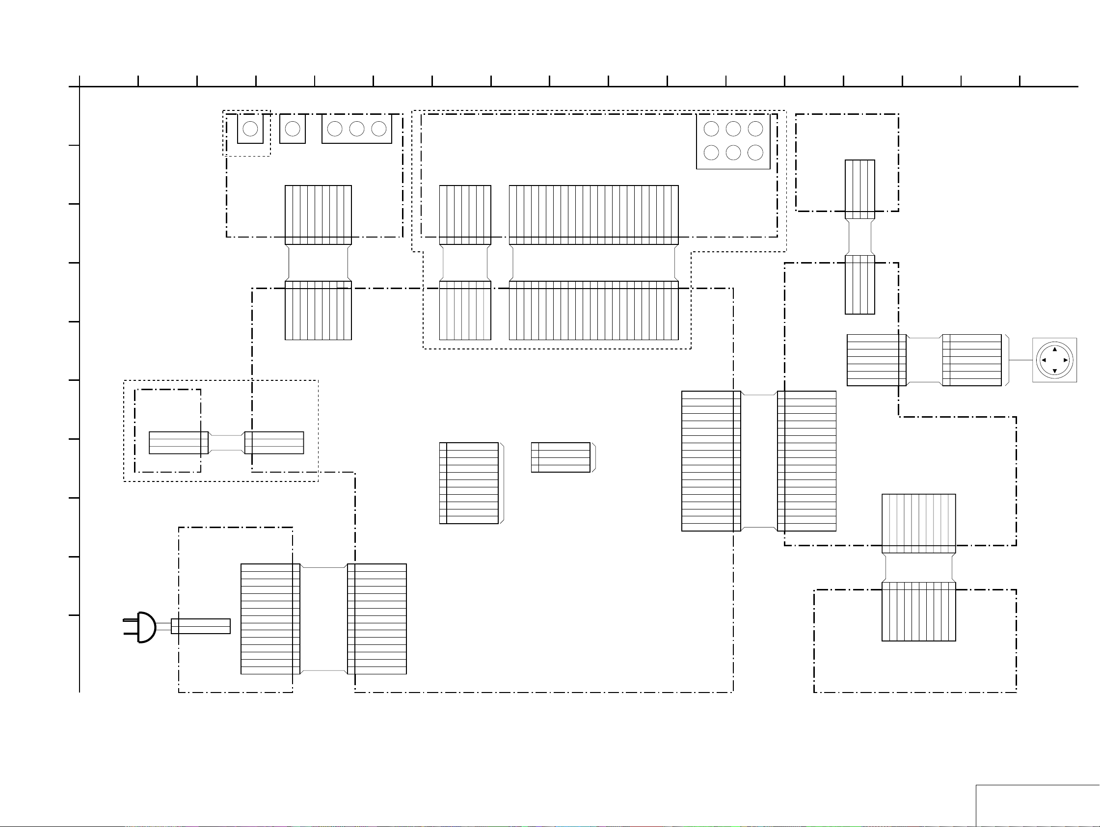
FRAME (2) SCHEMATIC DIAGRAM
DVP-C660/C670D/C675D
1
C670D:US,Canadian/C675D
51110
763
84
9 17
122 1615
13 14
A
19 LED_DATA
18 LED_CLK
17 LED_CS
16 LOAD
15 AD7
14 AD6
13 AD5
12 AD4
11 GND
10 GND
9 LED_CTRL
SW+5V
8
7 OPEN/CLOSE
6 PLAY
5 AD3
4 AD2
3 AD1
2 P_DET
1 SIRCS
SW-338 BOARD
4P
CN301
LOAD
123
123
4P
LOAD
CN103
19PCN102
AD7
AD6
GND
4
FS-134
4
AD6
AD7
GND
CN104
COMMON
RIGHT
ENTER
LEFT
DOWN
FL-113 BOARD
CN101 10P
10P
CN201
FR-170 BOARD
7P
1
2
GND
3
UP
4
FPC
5
6
7
AD1
P_DET
GND
LED+5V
GND
SW+5V
9
10
LED(3D)
8
B to B
123456789
AD1
GND
GND
P_DET
SW+5V
LED+5V
LED(3D)
LED(R2)
LED(R2)
1
2
3
4
5
6
7
LED(3DHP)
LED(3DHP)
COMMON
RIGHT
GND
UP
ENTER
LEFT
DOWN
LED(DD)
1234567
10
LED(DD)
COUSOR UNIT
ENTER
B-Y R-YY
J302
B
C
MEGA CONTROLS-LINK
CV-33 BOARD
9P
CN301
1 A1_OUT
2 AI_IN
3 S_LINK
4 GND
5Cr
FAC-003
1A1_OUT
2A1_IN
3S_LINK
4GND
D
9P
CN906
5Cr
E
C670D/C675D
F
HP-128
BOARD
CN501
3P
1HP-L
2HP-GND
AH-116
3HP-R
3PCN702
1
HP_L
2
HP_GND
3
HP_R
G
COMPONENT VIDEO OUT
6 GND
7Cb
8 GND
6GND
7Cb
8GND
J301J303
9Y
9Y
7P
CN401
7P
CN801
C670D/C675D
L-IN
R-IN
-8V
6CH_MUTE
7654321
FFCFFC
FAH-002
-8V
R-IN
L-IN
6CH_MUTE
(down load)
11PCN910
XFRST
1
XIFBUSY
2
XIFCS
3
SOO
4
SIO
5
SCO
6
GND
7
PCONT
8
GND
9
3.3VIN
10
IFRST
11
+8V
+8V
SW+5V
MEGA_MUTE
1234567
SW+5V
MEGA_MUTE
CH-97 BOARD
23P
LOUT1-
LOUT1+
CN402
23PCN802
CHECK
ROUT1+
GND
GND
123456789
23
GND
GND
LOUT1-
LOUT1+
ROUT1+
(diag)
CN911
4
TXD
3
RXD
2
GND
1
+3.3V
LOUT2-
ROUT1-
LOUT2+
GND
GND
GND
10111213141516171819202122
FAH-001
GND
GND
GND
ROUT1-
LOUT2+
4P
FFC
LOUT2-
ROUT2-
ROUT2+
GND
GND
10111213141516171819202122
GND
GND
ROUT2-
ROUT2+
LOUT3-
LOUT3-
ROUT3-
ROUT3+
GND
GND
23
123456789
GND
GND
ROUT3-
ROUT3+
LOUT3+
GND
GND
GND
GND
LOUT3+
CHECK
H
POWER BLOCK
MPW1240(C660/C670D:US,Canadian)
MPW1311(C670D:Australian,E/C675D)
I
CN1
2P
1
AC IN
2
AC IN
J
CN101
1P-DET
2P-CONT
3SW-11V
4SW-11V
5SW+5V
6SW+5V
7EVER+5V
PA-136
8SW+3.3V
9SW+3.3V
10D_GND
11D_GND
12M_GND
13M_GND
14SW-11V
15SW-11V
CN907
1 P-DET
2 P-CONT
3 SW+11V
4 SW+11V
5 SW+5V
6 SW+5V
7 EVER+5V
8 SW+3.3V
9 SW+3.3V
10 D_GND
11 D_GND
12 M_GND
13 M_GND
14 SW-11V
15 SW-11V
15P
AI-18 BOARD (2/2)
SW RR FR
CRLFL
J401
5.1CH OUTPUT
19PCN903
1LED_DATA
2LED_CLK
3LED_CS
4LOAD
5AD7
6AD6
7AD5
8AD4
9GND
FFC
10GND
FAF-001
11LED_CTRL
12SW+5V
13OPEN/CLOSE
14PLAY
15AD3
16AD2
17AD1
18P_DET
19SIRCS
05
FRAME (2/2)
4-5 4-6
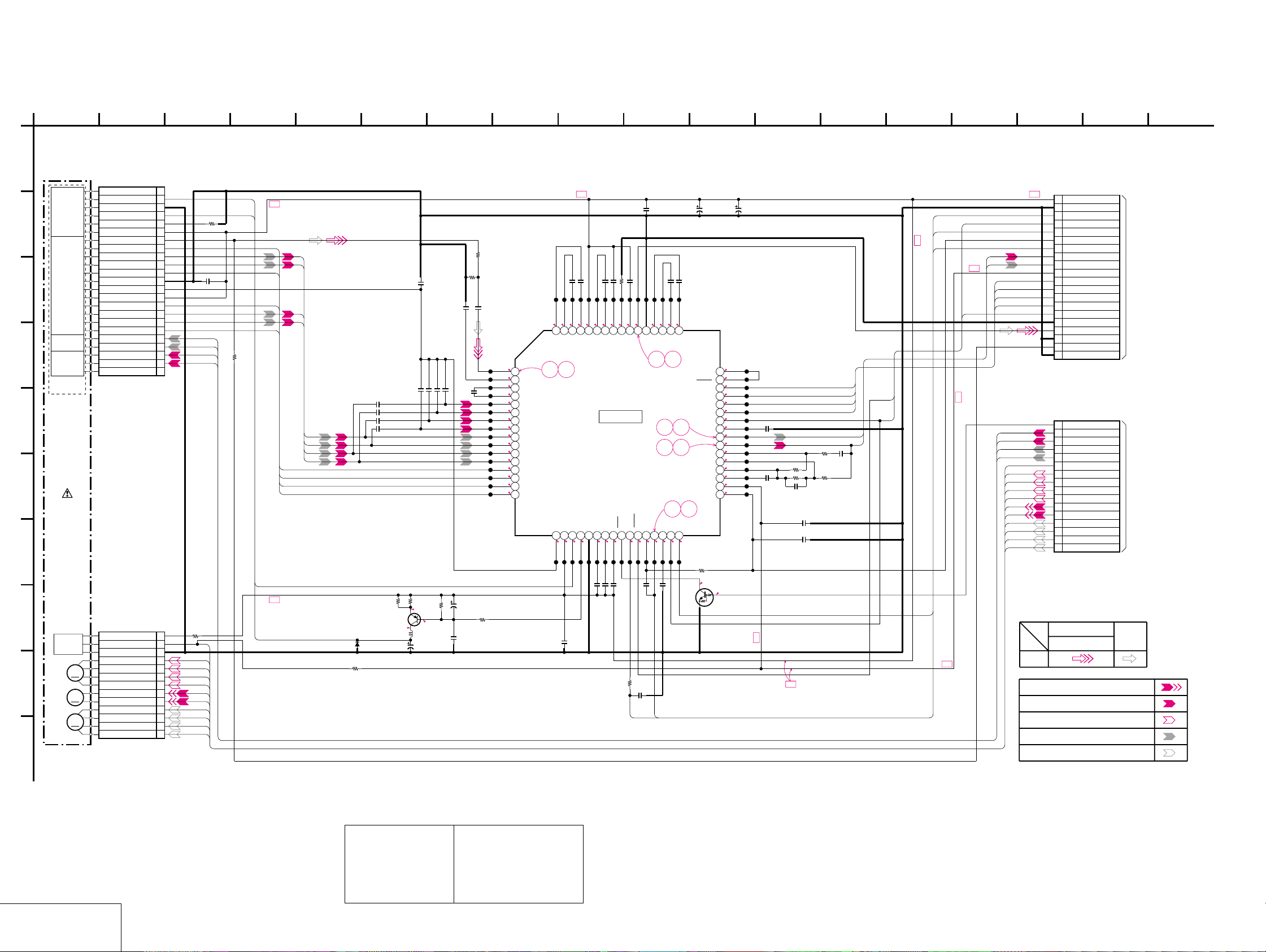
DVP-C660/C670D/C675D
TK-57 (RF/SERVO) SCHEMATIC DIAGRAM • See page 4-7 for printed wiring board and page 4-10 for waveforms.
– Ref. No.: TK-57 board; 3,000 series –
1
TK-57 BOARD
NO MARK:DVD/CD PLAY
A
DVD/CD
LD MODULE
B
DVD/CD
SPINDLE
05
KHM-220AAA
SLED
MOTOR
MOTOR
TILT
MOTOR
PD IC
FOCUS
COIL
TRACKING
COIL
OPTICAL
DEVICE
BASE UNIT
INLIMIT
SENSOR
M
M
M
C
D
E
G
H
I
J
23F4 12
CN001 23P
N.C. 1
LD 2
GND 3
PD 4
VR 5
VLD 6
RF 7
F8
C9
D10
H11
GND 12
VC(2.5V) 13
VCC(5V) 14
G15
A16
B17
E18
FCS+ 19
FCS- 20
TRK+ 21
TRK- 22
N.C. 23
LD
B+
PD
100R002
F
C
D
H
0.1u
C004
G
A
B
FCS+
FCS-
TRK+
TRK-
E
R003
100
C005
2200p
C007
2200p
C008
2200p
C009
C
D
A
B
E
F
G
H
2200p
C010
0.1u
C017
5600p
22p
22p
C014
C013
C011
22p
R022
150
R023
820
C019
5600p
CL004
CL005
CL006
CL007
CL008
CL009
CL010
CL011
CL012
CL013
CL014
CL015
CL016
CL017
CL018
CL019
3.4
1
3.4
2
3.4
3
3.4
4
2.5
5
2.5
6
2.5
7
2.5
8
2.6
9
2.6
10
2.6
11
2.6
12
2.6
13
2.6
14
2.6
15
2.6
16
22p
C015
C018
560p
CL020
3.7
64
12
RFIP
RFIN
CP
CN
A2
B2
C2
D2
D
C
B
A
E
F
G
H
911
B+
0.1uC022
0.1uC021
1200p
C026
0.001u
C024
CL022
CL024
CL026
CL028
CL030
CL032
CL034
3.7
3.4
3.4
4.9
2.9
2.9
3.0
58
59
62
ENV57CLM
VPA60AIP61AIN
ATON63ATOP
SSOUT
IC001
DVD/CD RF AMP
DIGITAL SERVO
IC001
SSI33P3722
12k
R009
CL036
0.6
0.01uC028
CL038
2.5
55RX56
105
C029
0.1u
0.1uC033
CL040
CL048
CL042
CL044
CL046
2.9
3.4
2.3
3.4
53
54
BYP
SIGO
C031
10u
16V
C034
0.1u
CL050
2.2
49
FNN
FNP50DIP51DIN52VNA
910
48
HOLD1
47
SIGDET
46
SDEN
45
SRD
44
SWD
43
SCLK
42
HOLD2
87
65
41
BYP2
40
FE
39
TE
38
TEI2
37
TEI
36
TEO
35
TZIN
34
VP3
33
VCI
34
DFT
VPB
VC
18PD19LD20
4.9
2.5
CL023
CL025
C020
0.1u
0.2
CL027
VNB
21MP22MB23
2.2
CL029
CL031
C023
0.1
CL033
0.047u
17
CL021
PD
R006
D003
R004
22k
R005
33
Q001
2SB1132-T100-QR
LD DRIVE
33
2.8
2.8
L001
47uH
C006
10u
16V
C012
R007
10u
47k
16V
R008
C016
0.01u
10
2.2
B+
13PCN002
R001
330
1LED
2INLIM
3GND
4SLB-(4)
5SLA+(2)
6SLB+(3)
7SLA-(1)
8SPM+
9SPM-
10TIB-(4)
11TIB+(3)
12TIA-(1)
13TIA+(2)
INLIM
SLA+
SLB+
SPM+
SPM-
SLB-
SLA-
TIB-
TIB+
TIA-
TIA+
LD
1SS355TE-17
FDCHG
MLPF
MIRR
LDON
24
25
26
27
28PI29
0
4.9
2.5
2.5
CL035
CL037
CL039
CL041
CL043
C027
150p
C030
0.047u
0.1u
R025
C041
220
2200p
MIRR
C025
TZC
MIN
TPH
30
31
32
0-0.40
3.0
2.3
2.5
R029
0.1u
C032
CL049
CL051
2.2M
0
0
Q002
UN5213-TX
INVERTER
CL045
PI
CL047
(Suffix-12)
0
0
0
1.5
3.3
3.3
0
2.7
1.9
2.0
1.8
1.9
1.8
2.5
3.3
1.9
CL052
CL053
CL054
CL055
CL056
CL057
CL058
CL059
CL060
CL061
CL062
CL063
CL064
CL065
CL066
CL067
13
C043
100u
6.3V
SSCS
0.047u
SSRD
SSWD
SSCK
C035
0.1u
R017
C040
4700
R015
10k
R016
10k
C036
C037
560p
C038
0.1u
C039
0.1u
6800p
R018
10k
SSDFCT
SSDFCTI
FE
TE
MIRR
TZC
B+
PI
TZC
157 14
SSDFCTI
TE
FE
B+
SSCK
SSWD
SSRD
SSCS
SSDFCT
B+
TRK-
TRK+
FCS-
FCS+
INLIM
SLB-
SLA+
SLB+
SLA-
SPM+
SPM-
TIB-
TIB+
TIA-
TIA+
B+
B+
B+
16 1786
B+
SIGNAL PATH
PB
SPINDLE SERVO(SPEED AND PHASE)
20PCN003
1
5V
2
GND
3
MIRR
4
SSDFCTI
5
TZC
6
SVC
7
PI
8
TE
9
FE
10
3.3V
11
SSCK
12
SSWD
13
SSRD
14
SSCS
15
SSDFCT
16
RF-
17
RF+
18
GND
19
RF MON
20
GND
16PCN004
1
XDRVMUTE
2
TRK-
3
TRK+
4
FCS-
5
FCS+
6
INLIM
7
SLB-
8
SLA+
9
SLB+
10
SLA-
11
SPM+
12
SPM-
13
TIB-
14
TIB+
15
TIA-
16
TIA+
VIDEO SIGNAL
Y/CHROMA
AUDIO
SIGNAL
MB-87 BOARD (6/10)
CN404
(SEE PAGE 4-29)
MB-87 BOARD (5/10)
CN405
(SEE PAGE 4-27)
18
TRACKING SERVO DVD/CD CDV
SLED SERVO DVD/CD
FOCUS SERVO
SKEW SERVO DVD/CD
RF/SERVO
TK-57
Note:
The components identified by mark 0 or dotted
line with mark 0 are critical for safety.
Replace only with part
number specified.
Note:
Les composants identifiés par
une marque 0 sont critiques
pour la sécurité.
Ne les remplacer que par une
pièce portant le numéro
spécifié.
4-11 4-12
 Loading...