

Page 1
TechnicalTraining
DVD
JanArtsJean-PierreCorgiatti
IanPatienceJaumeVillellaWinfriedWeist
“”
“”
Page 2

English
TM
Page 3

CONTENTS
Introduction: The Diverse, High Performance World of DVD........................................................... 4
Chapter 1 The High Capacity Optical Digital Disc for a New Era
Key Points ...........................................................................................................................................5
DVD disc construction and high-density recording ..........................................................................6
■Two 0.6 mm thick substrates bonded back-to-back .................................................................................6
■Laser beam wavelength and NA of the objective lens...............................................................................6
Four types of high-capacity disc....................................................................................................... 8
■Data reading and storing methods ........................................................................................................... 8
Modulation and error correction in the DVD system.........................................................................9
■EFM PLUS modulation...............................................................................................................................9
■DVD error correction system....................................................................................................................10
Five diverse formats are used in the DVD format group.................................................................11
DVD file systems ...............................................................................................................................12
Questions & Answers........................................................................................................................13
What is Write-once DVD?
Can pictures be recorded on DVD?
What about Rewritable DVD?
Chapter 2 Features of the DVD-Video Format
Key Points .........................................................................................................................................15
DVD-Video technology in detail .......................................................................................................16
■DVD-Video realizes high quality pictures, high quality sound, and multiple playback functions.............16
■Data volume distribution according to software contents .......................................................................16
High image quality technology (1) MPEG2 picture compression ...................................................18
■Why is data compressed? .......................................................................................................................18
■Profile and level of MPEG2 ......................................................................................................................18
■Hybrid coding by combining three main methods...................................................................................19
Questions & Answers........................................................................................................................19
What is MPEG?
Spatial axis compression - discrete cosine transform....................................................................20
■DCT removes unnoticeable frequency elements .....................................................................................20
Time axis compression - predictive coding with motion compensation........................................21
■Using preceding and succeeding pictures to predict motion ..................................................................21
■Motion Compensation extracts only motion changes .............................................................................21
Time axis compression - GOP construction and bi-directional prediction....................................22
■GOP construction by I, P, and B picture ..................................................................................................22
■The P picture and B picture .....................................................................................................................22
Huffman coding.................................................................................................................................23
■Huffman coding: a statistical method for data compression...................................................................23
Questions & Answers........................................................................................................................23
What is 4:2:0 coding in MP@ML?
Are there any differences between DV and DVD data compression? ............................................24
Bit rate technology in DVD-Video (2) variable transmission rate....................................................25
■Variable bit rate allows highly efficient image storage .............................................................................25
DVD-Video’s superb audio capabilities ...........................................................................................26
DVD-Video’s high fidelity (1) - Dolby Digital (AC-3) .........................................................................27
■Various Dolby Digital (AC-3) modes.........................................................................................................27
■Full-band 5.1 channel surround ...............................................................................................................27
■High efficiency coding method of Dolby Digital AC-3 .............................................................................28
DVD-Video’s high fidelity (2) - MPEG Audio ....................................................................................29
■Multi-channel surround ............................................................................................................................29
■Features of the MPEG Audio system.......................................................................................................29
■MPEG Audio’s high efficiency coding method.........................................................................................29
DVD-Video’s high fidelity (3) - linear PCM Recording ..................................................................... 30
■Linear PCM delivers the highest level of sound quality ...........................................................................30
Multiple-language function...............................................................................................................30
■Multiple-language dubbing of up to eight languages ..............................................................................30
■Multiple-language subtitling of up to 32 languages.................................................................................30
2
Page 4

Stream and packet transmission .....................................................................................................31
■“Stream” data flow...................................................................................................................................31
■Transmission by packet multiplexing .......................................................................................................31
DVD-Video interactive operation......................................................................................................32
■Title menu and DVD menu .......................................................................................................................32
■Multi-story function ..................................................................................................................................32
■Multi-angle functioning up to nine angles................................................................................................33
■Parental lock function (optional standard) ...............................................................................................33
■Multi-aspect ratio capability.....................................................................................................................34
Questions & Answers........................................................................................................................34
How does seamless playback work?
Copyright protection system in DVD-Video.....................................................................................35
■“Regional Code” controls playback in six regions of the world...............................................................35
■“Copy Protection System” links software and hardware .........................................................................35
DVD-Video software production ......................................................................................................36
■Telecine ....................................................................................................................................................36
■Authoring - the process ...........................................................................................................................36
■Authoring - MPEG2 video encoding ........................................................................................................36
■Disc manufacturing ..................................................................................................................................37
Chapter 3 Sony’s new DVP-S715 and DVP-S315 DVD players
Main Features ...................................................................................................................................39
Main Specifications of the DVP-S715 ..............................................................................................40
Main Specifications of the DVP-S315 ..............................................................................................41
Extremely high precision optical pickup network ...........................................................................42
■Dual discrete optical pick-up ...................................................................................................................42
■New digital RF processing LSI.................................................................................................................42
■New programmable DSP servo................................................................................................................42
■Tilt servo maintains disc reading accuracy..............................................................................................43
■Quick access drive...................................................................................................................................43
■Resonance-damping disc tray .................................................................................................................43
Questions & Answers........................................................................................................................43
What is jitter?
High precision digital image processing..........................................................................................44
■Smooth Scan easily indicates search direction .......................................................................................44
■Slow motion and frame-by-frame playback ............................................................................................44
■High-precision 10 bit video processing and D/A converter.....................................................................45
■Digital Noise Reduction (DNR) .................................................................................................................45
■Video pause with auto field/frame mode selection..................................................................................46
■High quality letter box conversion ...........................................................................................................47
High-end CD player technology for high-end sound ......................................................................48
■Sony’s new 96kHz/24 bit D/A Converter .................................................................................................48
■Variable Coefficient (VC) digital filter ........................................................................................................48
■24 bit processing for precise soundtrack decoding ................................................................................48
■R-core transformer...................................................................................................................................49
■Off-center anti-resonant feet....................................................................................................................49
■Ultra high-performance audio circuits .....................................................................................................49
■Optical and coaxial digital audio output terminals...................................................................................50
Questions & Answers........................................................................................................................50
How is AC-3 recorded on a laserdisc?
Full-function remote commander and GUI ......................................................................................51
■User-friendly design for ultimate enjoyment ............................................................................................51
■GUI makes operation easy.......................................................................................................................51
■Video bit allocation can be displayed ......................................................................................................51
■Multi-level dimmer....................................................................................................................................51
■Screen Saver 51
Manufactured under license from Dolby Laboratories Licensing Corporation.
“Dolby”, the double-D symbol , “Pro Logic” and “AC-3” are trademarks of Dolby Laboratories Licensing Corporation.
3
Page 5

Welcome to the next generation in
optical disc media
Announcing the Diverse, High Performance World of DVD
The digital audio era began in the fall of 1982 with
the release of the Compact Disc and the CDP-101,
the Sony’s first CD player. The CD represented a
true breakthrough in sound reproduction. Just 12
cm in diameter, it was only a fraction of the size of
vinyl analog records popular at the time. But the
CD, with its highly dynamic, crystal clear sound,
not to mention the sheer convenience of random
access, soon eclipsed analog records to become a
leading form of music software.
The CD format proved too good for music alone. In
the 1980s, it was applied in the rapidly progressing
computer field as a quick-retrieval data storage
system called CD- ROM. Not only is CD-ROM
software extremely convenient, it is also
remarkably inexpensive to manufacture. The
subsequent development of Video CD and Photo
CD was proof that the era of optical disc media
had arrived.
Interestingly enough, the CD was not the first
consumer- use optical disc media. It was preceded
by the LaserDisc in 1980. This 30 cm disc, roughly
the same size as the analog record, was designed
to hold up to one hour of high quality audio and
video per disc side.
Although the LaserDisc and CD differ in size, signal
recording system, and contents, they are
fundamentally similar in their method of recording
on micron-order pit rows and playback by laser
pickup. As the first step toward practical
application of optical disc media, the development
of the LaserDisc began in the 1960s with the
dream of creating “records which can also display
images.”
In the nearly two decades since the release of the
LaserDisc, a broad array of technological advances
in basic materials, hardware, software, and digital
processing have given birth to an exciting new
optical disc video format. DVD-Video is now a
reality, offering superior performance in every
parameter of operation.
DVD-Video, just one of the many proposed forms
of the DVD format, is the same size as the CD, yet
boasts far higher data storage capacity. In
combination with the highly advanced MPEG2
data compression technology, an entire movie —
with multiple soundtracks and subtitle choices —
can be recorded and played back on a single disc
with full-quality image and sound reproduction.
DVD-Video was joined by DVD-ROM, which was
standardized at the same time, then followed by
DVD-R and DVD-RAM, which were subsequently
standardized, as universal formats. DVD-Audio is
currently being studied for standardization. These
media are expected to play a central role in the
coming age of multi-media and information
technology.
■History of Optical Discs
LaserDisc
introduced
1980 1982 1991 1997
Compact
Disc introduced
MO (magneto-optical disc)
introduced
■Evolution of the CD format
Red
Book
1981
CD-DA
Yellow
Book
1985
CD-G
1985
CD-ROM
Green
Book
(International Organization for
Standardization format)
1986
1987 1996
CD-V
1987
ISO9660
CD-I
Orange
Book
1988
CD-ROM XA
(extended format)
1989
CD-R
White
Book
1992
Blue
Book
1994
Photo CD
CD TEXT
1996
CD Extra
Video CD
1996
CD-RW
DVD introduced
4
Page 6

Chapter One
The High Capacity Optical Digital Disc for
a New Era
A remarkably large storage capacity, the primary feature
of DVD, has been realized by higher recording density
made possible by advanced technology developed after
the introduction of the CD. The storage capacity of DVD
is 4.7 GB (gigabytes) by recording on a basic single
sided, single layer disc. This is approximately seven
times greater than that of the CD.
In addition to this basic single side, single layer disc,
there are three other types of discs: 1) the single sided,
dual layer disc which can store 8.5 GB of data; 2) the
double sided, single layer disc; and 3) the double sided,
dual layer disc. The latter two, respectively are the
double-sided versions of the single side, single layer and
single side, dual layer discs. At present, four types of
discs have been standardized.
In addition to DVD-Video, DVD-ROM, DVD-R (writeonce media) and DVD-RAM (rewritable media), for which
specifications have already been published, DVD-Audio
is being studied for standardization. This makes for a
total of five DVD categories.
In this chapter, our discussion is focused on the physical
format and fundamental signal process. DVD-Video will
be taken up in Chapter 2.
Key Points
●High density optical disc for the next generation which realizes a large capacity of 4.7 GB (single
side, single layer), approximately seven times greater than that of CD.
●Four disc types: single sided, single layer (4.7 GB); single sided dual layer (8.5 GB); double sided,
single layer (4.7 GBx2); double sided, dual layer (8.5 GBx2).
●Minimum pit length and track pitch are approximately one half of those of the CD. Primary
technologies which made this high density storage possible are:
(1) Short wavelength red semiconductor laser.
(2) Improved numerical aperture (NA) of the objective lens.
(3) Disc construction using thin 0.6 mm substrate.
●Signal processing capability for the optical disc system was improved in both modulation and
error correction.
●Five disc categories have been defined: DVD-Video, DVD-ROM, DVD-Audio, DVD-R, and DVD-
RAM.
●Making use of its large storage capacity and interactive characteristics, DVD is more than just a
video disc. In the coming multi-media era, DVD represents a new data medium for a variety of
applications in many different fields.
5
Page 7

DVD disc construction and high-density recording
t=1.2mm
t=0.6mm
A
A
A
'
A
'
thickness of the disc thickness of the disc
Even a single sided, single layer DVD has about seven
times the storage capacity of CD. What has made this
large storage capacity possible is new technology in
high density recording and reproduction.
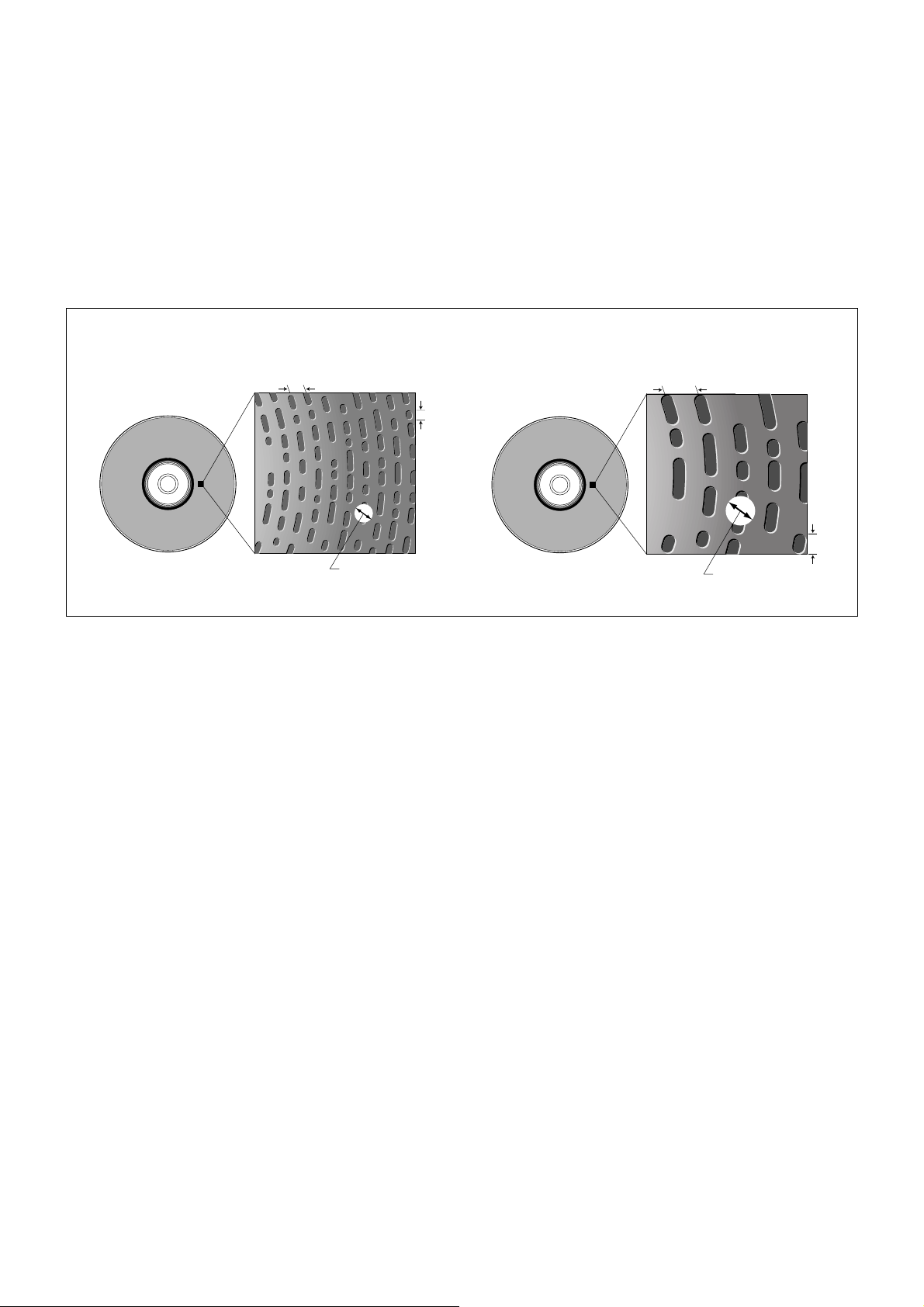
Minimum pit length in DVD is 0.4 microns, with a track
pitch of 0.74 microns. Both are approximately half of
those of the CD. This has been made possible by
making the laser beam spot much smaller than that of
the CD. The main technical approach used to make the
■Basic Specifications of DVD
DVD-Video/
DVD-ROM
(Single sided,
single layer type)
DVD-Video/
DVD-ROM
(Single sided,
dual layer type)
disc
diameter
disc
thickness
(two 0.6mm
substrates
bonded)
(two 0.6mm
substrates
bonded)
minimum
pit
length
maximum
pit
length
track
pitch
sector
alignment
CLV
CLV
laser beam spot smaller is the use of a laser beam with
shorter wavelength, and the adoption of a larger
objective lens numerical aperture (NA). Improved signal
processing of data encoding (modulation format) and
error correction and reduction of data redundancy also
contributed to an increase in storage capacity. In
addition, the storage capacity of DVD can be greatly
increased by using both dual layer and double sided
configurations.
reference
scanning
linear
velocity
ISO9660
ISO9660
file system modulation
UDF Bridge
(
UDF &
UDF Bridge
(
UDF &
EFM plus
(
8-16
)
EFM plus
(
8-16
)
correction
)
)
error
RS-PC
RS-PC
readout
wavelength
of laser
diode
(reference)
650/
635nm
650/
635nm
NA of
objective
lens
(reference)
0.6 4.7GB
0.6 8.5GB
data
capacity
CD-ROM
CLV EFM CIRC
ISO9660
0.45780nm
■Two 0.6 mm substrates bonded back-to-back
The DVD disc itself is 1.2 mm thick and 120 mm in
diameter and is made of polycarbonate, the same as a
CD. The disc consists of two 0.6 mm thick substrates
bonded back-to-back, while the CD is composed of a
single substrate. This has an advantage of minimizing
the effects of the inclination of recorded surface against
the incident laser beam (discrepancy against vertical
angle) or tilt angle, thus reducing reading errors and
contributing to higher storage density.
■Effects of tilt angle differ by disc thickness.
The thicker a disc is, the larger the difference in length there
is between A and A’
■Relationship between the laser beam’s wavelength and the NA of the objective lens
The diameter of the laser beam spot is in proportion to
the laser beam’s wavelength, and is in inverse proportion
to the numerical aperture of the objective lens. In DVD, a
red semiconductor laser beam with a short wavelength
of 650 nanometers or 635 nanometers is employed,
while the CD uses a 780 nanometer laser beam. The
numerical aperture (NA) of the objective lens of a DVD
pickup is 0.6, larger than the 0.45 of the CD. This
enables focusing the laser beam to a smaller spot than
with the CD, so pit sizes and track pitch can be made
smaller, resulting in higher storage density on a given
disc size.
0.68GB
6
Page 8
The larger the NA of the objective lens, the smaller the
tolerance of the tilt angle. However, the DVD uses two
0.6 mm thick substrates bonded back-to-back, and
necessary reading precision is maintained. The physical
recording density of the DVD is 4.6 times as dense as
that of the CD. In addition to these improvements in
physical precision, improved signal processing in data
encoding (modulation) and error correction also
contribute to higher data capacity of the DVD.
■
DVD vs CD in pit length and track pitch
DVD
track pitch: 0.74 µm
beam spot Ø0.9 µm
minimum pit length:
CD
0.4
µm
track pitch: 1.6 µm
beam spot ø1.4 µm
minimum pit length:
0.83
µm
7
Page 9
Four types of high-capacity disc construction
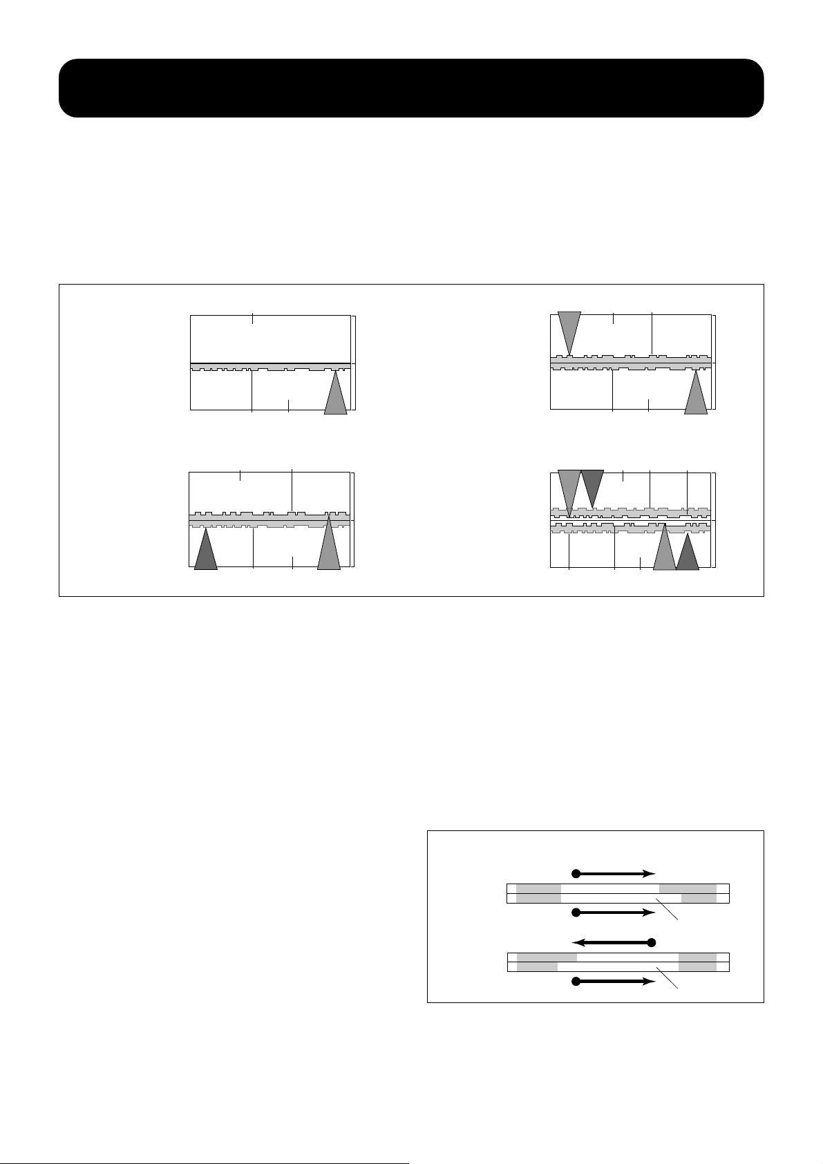
Four different types of disc construction have been
standardized: single sided, single layer; single sided,
dual layer; double sided, single layer; double sided, dual
layer disc. The single sided, single layer disc is quite
similar to CD except that its substrate is 0.6 mm thick.
The double sided, single layer disc is composed of two
■Single sided,
single layer disc:
4.7 GB storage
capacity
■Single sided,
dual layer disc:
8.5 GB storage
capacity
disc
thickness
1.2mm
disc
thickness
1.2mm
substrate
reflective layer
substrate
substrate
reflective layer
0.6mm
0.6mm
laser beam
0.6mm
0.6mm
single side, single layer substrates bonded back-toback. The single sided, dual layer disc is a single sided,
single layer disc having one more storage layer beyond
the first layer. To enable the pickup to read data on the
second layer, the first layer is covered by semi-reflective
material.
■Double sided,
single layer disc:
9.4 GB storage
capacity
■Double sided,
dual layer disc: 17
GB storage
capacity
disc
thickness
1.2mm
disc
thickness
1.2mm
laser beam
laser beam
substrate
reflective layer
substrate
reflective layer
substrate
semi-reflective
layer
laser beam
reflective
layer
0.6mm
0.6mm
0.6mm
0.6mm
semi-reflective
layer
substrate
laser beamlaser beam
■Data reading and recording methods
In the case of the single sided, single layer disc and the
single sided, dual layer disc, the data is read from one
side of the disc as is done with CD. With the double
sided, single layer disc and the double sided, dual layer
disc, the data must be read from both sides of the disc.
Data is recorded from the inner circumference to the
outer, like with CD, except for dual layer discs (both
single sided and double sided).
There are two methods of recording dual layer DVD. One
method is to record data on both layers from the inner
circumference to the outer (parallel track path) and the
other is to record data from the inner circumference to
the outer on the first layer and from the outer to the inner
on the second layer (opposite track path). Data is
regarded as a single volume in either method, and
producers can select either method depending on the
content of the software and the purpose of its
expression.
semi-reflective
layer
reflective
layer
substrate
laser beam
■Recording method for the dual layer disc
2
parallel
track path
opposite
track path
lead-in area lead-out area
lead-out area
lead-in area
1
1
data area
2
middle area
data area
8
Page 10
Modulation and error correction
■EFM PLUS Modulation
in the DVD system
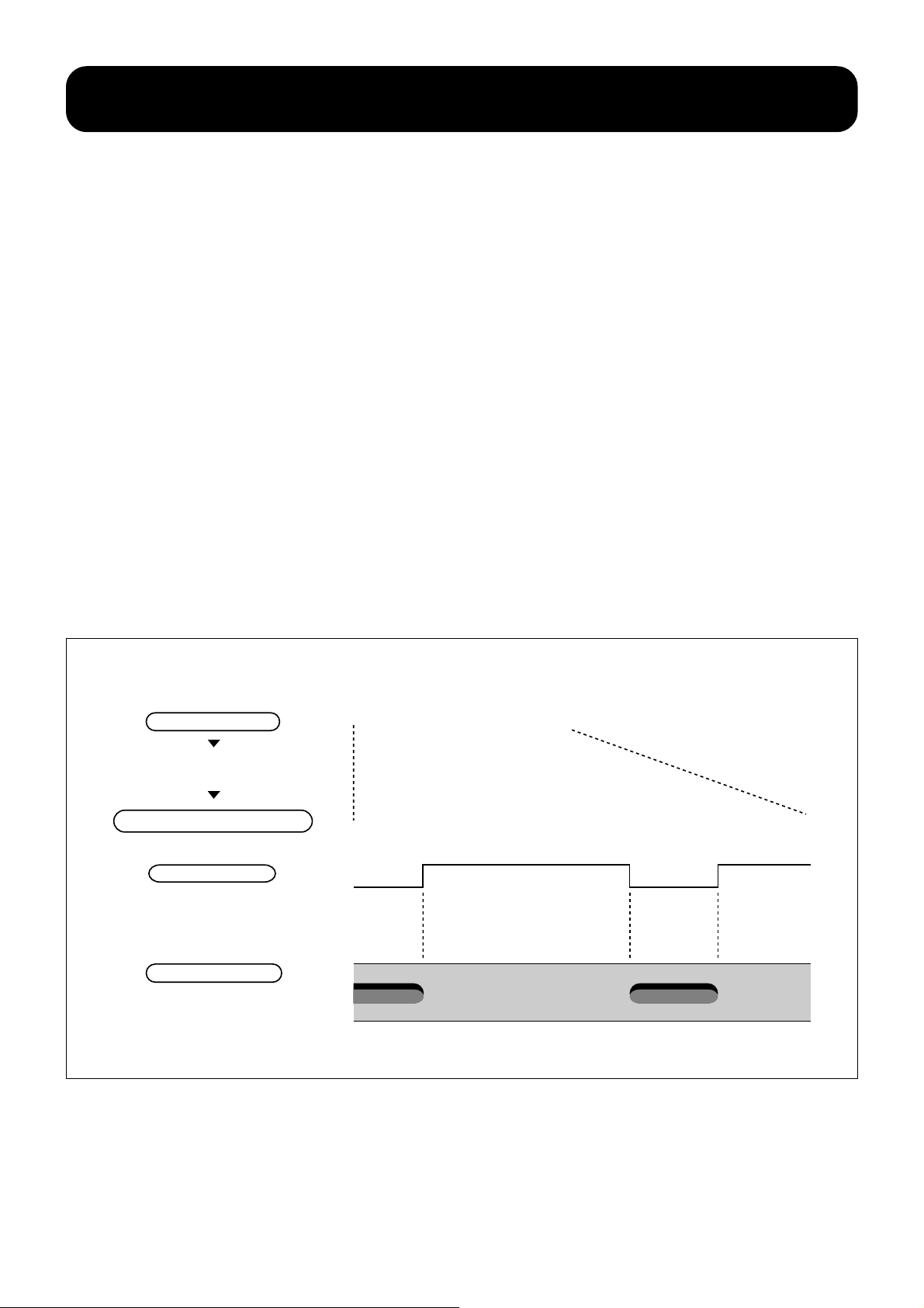
In recording data on the disc, the “EFM plus (8-16
modulation) format” is employed to encode the source
data for storage on the DVD. Digital signals are normally
encoded prior to recording them on the storage media
instead of recording them as they are (taking the CD and
DVD as examples; the “0s” and “1s” of the original data
are not formed in pits as they are). By EFM the signals, a
much larger volume of data can be recorded on a track
of the same length. EFM is performed to improve the
efficiency (linear storage density) of the recorded wave
form.
In CD and DVD, the original data constructed in 8-bit
units are translated into blocks of 14-bit or 16-bit
patterns using the conversion table. (This is called 8-14
modulation or 8-16 modulation.) The edges of pits
pressed on the disc indicate where “1s” appear in the
successive patterns of “0s” and “1s.” The principle
of the modulation format called Non Return to Zero
Inverse (NRZI) is used here.
The 8-16 modulation of the EFM plus format used in
DVD is the improved version of the 8-14 modulation of
the EFM format adopted in the CD. This 8-16
modulation may appear inefficient when compared to 814 modulation because 16 bits are used instead of 14
bits. In actual practice, however, it achieves a higher
storage density. A total of 17 bits (14+3=17) are required
because 3 merging bits are used to link the blocks of 14
bits in the EFM, while a multiple number of conversion
tables are used (only one conversion table is used in
EFM) to suppress indispensable DC components
needed to form the optical disc system and merging bits
are not required in EFM plus. The EFM plus format
increases storage density by approximately 6 % when
compared to the EFM format. (Note 1)
Note 1: (17-16)/16=0.0625
■8-16 modulation and pit pattern
8-bit data
The original 8-bit data is
translated into a 16-bit pattern by
the conversion table.
EFM plus modulation (16 bits)
recorded wave form
Recorded wave form reverses phase
if "1" comes and maintains
the phase when "0" comes.
pit pattern
Boundaries between the pits and
intervening reflective area
on the disc, or pit edges, are "1s".
00000111
0010000001001000
9
Page 11

■DVD error correction system
In digital data media, errors or data dropouts in
recording data due to scratches on the disc, disc
vibration and other causes need to be corrected. Error
correction is done by adding error correcting codes.
Data with those codes are modulated, and then pits are
formed. By adding those codes, mistakes made in
reading data are corrected.
The ratio of added codes in the total data, which
includes the original data, is called data redundancy. The
■Error correction system for DVD
The following explains the principle of data correction in digital data recording:
original data
RS-PC (Reed-Solomon Product Code) system is used
for error correction in DVD. This has more error
correcting capability than the CIRC (Cross Interleave
Reed-Solomon Code) used in the CD, and also
boasts lower data redundancy. Burst error correction
capability, which is expressed by how long a pit row on
the disc can be corrected, of a DVD player is about 6
mm versus about 2 mm of a CD player.
011
011
error correcting codes
are added
Digitized data are arranged in the
table as shown on the left.
001
011
0
001
100
011
0
011
100
(B)
011
011
001
row error correcting codes
0
011
(a)
1
column error correcting codes
An error occurs
when reading data
on the disc.
0
011
(A)
1
locating and
correcting an error
For example, a code is added to
make the number of “1” in the row
and column even.
Taking (a) as an example, a code “1”
is added to make the number of "1"
in the row "001" even.
The number of “1” in the row and
column is checked.
The number of “1” is decided to be
even after a code is added, so an
error must be generated somewhere
in either row (A) or column (B).
The data where the row (A) and
column (B) cross is erroneous
data. There is a “1” which is an error
and we know the correct value is
“0”. The data is restored to the
correct value.
10
Naturally, the error correction system actually employed is much more
complicated, and it can correct more complicated errors.
Page 12

Five diverse formats make up the DVD format group
In the DVD format group, there are five format variations:
DVD-Video, DVD- ROM, DVD-R, DVD-Audio, and DVDRAM. They can be classified by the kind of data
application and whether it is read-only or read-writable.
The physical and logical formats for each format are
defined in published specifications; DVD-Video in Book
B, DVD-ROM in Book A, DVD-R in Book D and DVDRAM in Book E. Specifications for DVD-Audio is
currently under study as Book C, respectively Looking at
■Five DVD format variations
Designation
DVD-Video
DVD-ROM
Type Application Status of specs
Read only
Read only
High quality package media for movie film
software with pictures and sound
Large capacity data media that allows high
quality multi-media application programs
for use with computers.
these five DVD categories from the standpoint of the
physical format; the read-only types such as CD-ROM
(Book A), DVD-Video (Book B), and DVD-Audio (Book C)
use the same format, while the recordable DVD-R (Book
D) and DVD-RAM (Book E) use independently separate
formats. As a file system for use with personal
computers, the UDF subset is employed on the readonly disc to facilitate compatibility.
Specs published in Sept.
1996 (Book B)
Specs published in Sept.
1996 (Book A)
DVD-Audio
DVD-R
(
Write Once
DVD-RAM
(
Rewritable
*3.95 GB/single sided **2.6 GB/single sided
)
)
Read only
Write once
Rewritable
High sound quality package media specifically
for music
Large capacity and write once data media for
computers
Large capacity and rewritable data media for
computers
Under study
*Specs published in July
1997 (Book D)
**Specs published in July
1997 (Book E)
As of January 1998
11
Page 13

DVD file systems
UDF (Universal Disc Format) is adopted as a file format
in DVD. It was devised by OSTA (Optical Storage
Technology Association, an international organization)
which consists of some fifty optical storage media
related companies. The “UDF-Bridge” shown in the
figure below, which extends to DVD-ROM, DVD-Video,
■Format construction and applicable books
application layer
volume layer
physical layer
format name
DVD-ROM
video
data format
UDF-Bridge UDF
physical format
read-only disc
DVD-Audio, and DVD-R, means that the bridge format
which makes the conventional ISO 9660 valid as a
subset of the UDF for DVD is used. The ISO 9660,
which was originally devised as the file format for CDROM, is used to make the DVD compatible with CDROM.
audio
data format
physical
format
write-once
disc
DVD-AudioDVD-Video
physical
format
rewritable disc
DVD-RAMDVD-R
Book ABook Book B Book C Book D Book E
12
Page 14
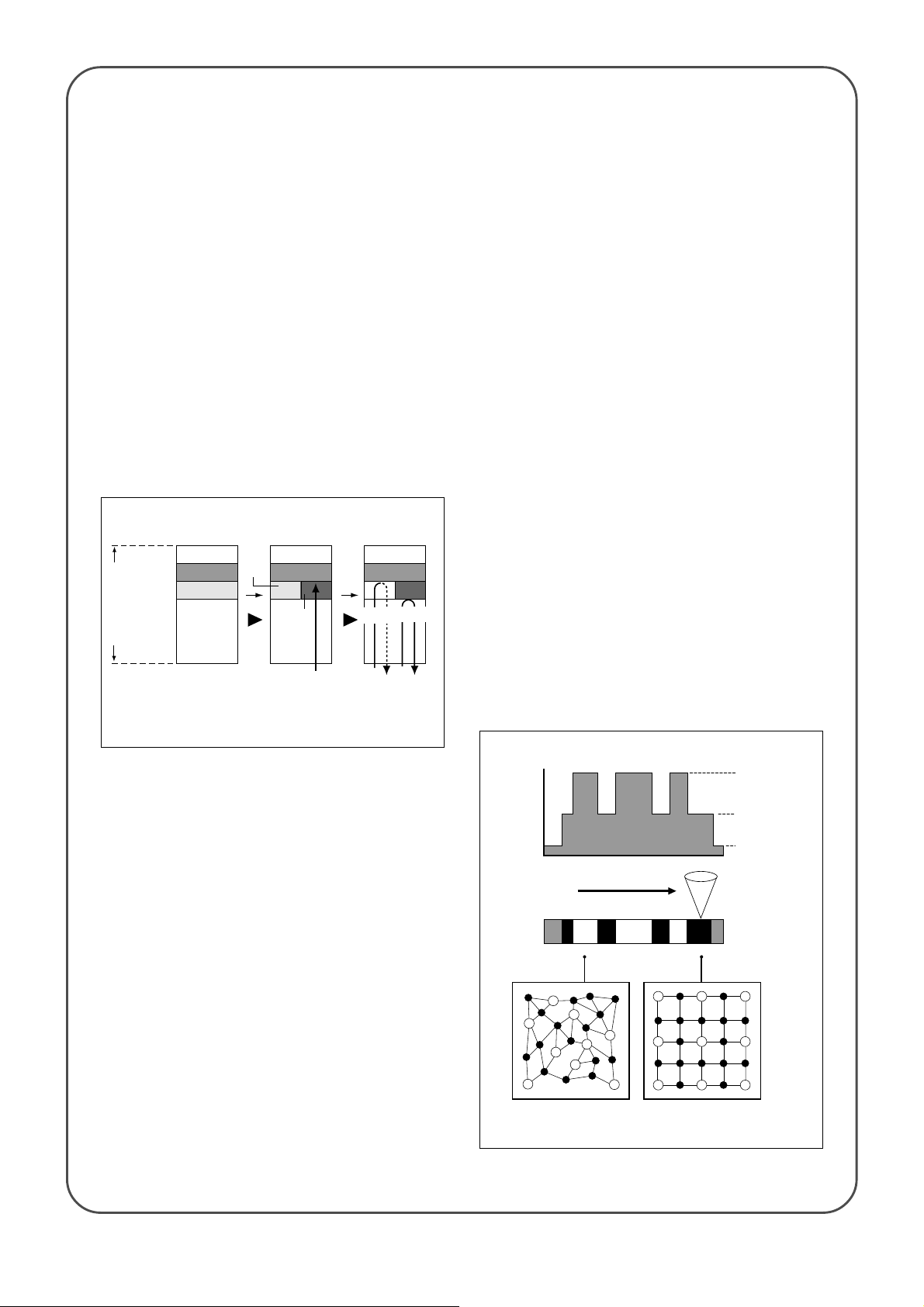
Questions & Answers
What is write-once DVD?
Write-once DVD, DVD-R, can be recorded only
once. Its data recording layer is coated by a
proprietary organic dye. Recording is performed by
applying a powerful laser beam on the layer.
Thermal change takes place at the spot radiated by
the powerful laser beam and the light absorbing
property of the spot becomes smaller than the part
not radiated. In reading data, digital signals
consisting of “0s” and “1s” can be retrieved by the
change in reflectance of data reading laser beam
like data is retrieved by existence of pits in the CD.
Spots thermally changed do not change even
when they are radiated by the relatively weak datareading laser beam and data once recorded cannot
be rewritten or overwritten.
Data recording and playback principle of DVD-R
protective
coating
reflective
coating
organic dye
polycarbonate
cross section of the disc
spot not
radiated
by the
laser
beam
recorded
Dye on the spot
chemically changes by
radiation of a powerful
laser beam and its light
absorbing property
also changes.
powerful
laser beam
reading recorded unrecorded
recorded
unrecorded
spot
part
weak
laser beam
Differences in the
reflective ratio are
obtained from the spot
radiated by laser beam
and the part not
radiated.
Can pictures be recorded on DVD?
We have explained that DVD-Video is a read-only
format and the rewritable DVD-RAM is currently still
being discussed. Will a disc that can record video
and audio with quality and time duration equivalent
to DVD-Video be available from other format
variations in the DVD group?
The answer is that it will be some time in the future
until such a disc will be available for home use. The
reasons are the lack of storage capacity (data
capacity of DVD-RAM is about 2.6 GB which is still
smaller than the 4.7 GB of DVD-Video) and some
as-yet undiscovered technical breakthroughs such
as video signal encoding LSIs. In addition to these
technical obstacles, there are very important
unavoidable problems in protecting the copyrights
which cover various digital information, not to
mention for moving pictures and sound. Sony is
presently engaged in various activities to address
these problems.
What about Rewritable DVD?
This is called DVD-RAM, and is a rewritable type of
DVD disc. For the data recording layer, it uses a
metal compound that reverses its phase from a
crystallized state (crystalline phase) to an
amorphous state (non-crystalline phase) and vice
versa by the methods used to heat and cool the
compound. The compound is rapidly heated and
cooled by radiating a powerful laser beam to create
an amorphous state spot on the crystalline state
recording layer to record data. This type of disc is
generally called a “phase change optical disc”
because data is read using diverse reflectance of
the amorphous state spots and the crystalline state
parts caused by phase transition.
Data can be written repeatedly on the disc
because amorphous state spots revert to a
crystalline state if a weak laser beam is radiated on
them and then cooled gradually. By controlling the
power of laser beam radiated on the recording
layer, simultaneous erasing and writing or direct
overwriting can be
performed.
phase change recording principle
recording power
laser
power
media
amorphous state
(molecular arrangement
diagram)
laser
(molecular arrangement
crystalline state
diagram)
erasing power
read-out power
13
Page 15

14
Page 16
Chapter Two
Features of the DVD-Video Format
The world of DVD begins with the advent of DVD-Video,
while the world of CD began with the music CD (CDDA).
As the storage capacity of DVD was initially aimed at
enabling the recording of an entire movie on a single
disc, DVD-Video is designed to make the dream of
enjoying pictures and sound with theater quality in the
home entertainment. As a new home entertainment
media, DVD-Video has many features which have not
been available from conventional package media. In this
chapter, we will highlight the technology which has
realized high quality video and audio from a compact
120 mm disc, and describe the many unique features
Key
●An entire movie can be stored on a disc the same size as a CD by making use of its large
storage capacity.
●Picture quality close to that of the Digital Video Format D1 used for professional video
masters has been realized by the adoption of MPEG2 compression.
●The same realistic sound and excitement as in movie theaters can be enjoyed in homes
through the high-fidelity 5.1 Channel Surround of the Dolby Digital (AC-3) System, and the
high-fidelity 5.1/7.1 Channel Surround of the MPEG system.
●Interactive software, with features such as the multi-story function which allows users to
select a story and the multi-angle function for the selection of viewing angles, can be
designed.
●The multi-language function allows dubbing of up to eight language soundtracks, and
subtitles in a maximum of 32 languages. The multi-aspect function enables the reception
of wide pictures on your TV screen.
15
Page 17

DVD-Video technology in detail
■
DVD-Video realizes high quality pictures, high quality sound, and multiple
playback functions.
The main features of DVD-Video can be summarized as
high quality pictures, high quality sound, and multiple
playback functions which are made possible by its large
storage capacity and digital signal processing. In terms
of picture quality, high quality images have been realized
with 500TV-line resolution, better than either laserdisc
or CD-Video.
The Dolby Digital (AC-3) System and the MPEG Audio
System are adopted for sound in addition to the linear
PCM audio. The 7.1/5.1 channel surround in the MPEG
system reproduces high quality sound, while the 5.1
channel surround in the Dolby Digital (AC-3) system
offers high fidelity sound with a very impressive and
realistic sound field not available with Dolby Pro Logic.
Using these high quality pictures and high quality sound
The most remarkable feature of DVD-Video
is that it offers both the highest
picture quality of home video media and
as a basis, interactive functions such as the multi-story,
multi-angle, and multi- language functions are also
achieved.
the capability to record an entire movie, which requires a
long recording time, all available on a single disc the
same size as a CD.
■Video and sound specifications for DVD-Video
DVD-Video
video compression system
resolution (pixels)
horizontal resolution
compression ratio
video
video bit rate
field/frame
aspect ratio
audio
audio system
audio bit rate
audio
number of channels
quantization bit sampling
frequency
others
Note 1: In the case of PAL, DVD-Video is not compatible with the high definition system. Note 2: Either Dolby Digital, MPEG or Linear PCM can be selected for each audio system.
subtitles
MPEG Linear PCM
max. 912 kbps
(per stream)
max 7.1 ch. /
stream
48 kHz 48 kHz
MPEG2 (MP@ML)
720 x 576 pixels (Note 1.)
approx. 500 TV lines
approx. 1/40
9.8 Mbps, max. (variable)
field/frame
4:3/16:9 (pan scan/letter box)
8 streams, max. (Note 2)
Dolby Digital (AC-3)
max. 448 kbps
(per stream)
max 5.1 ch. /
stream
2 bits, run length bit map system,
32 streams, max.
max. 6.144 Mbps
16-bit, 20-bit, 24-bit
(per stream)
max 8 ch. /
stream
48 kHz, 96 kHz
approx. 250 TV lines (same as VHS)
Video CD
MPEG1
352 x 286 pixels (Note 1)
approx. 1/140
1.15 Mbps (fixed)
frame
4:3
2 channel (stereo)
MPEG1 layer 2
224kbps (fixed)
2 ch only
16-bit 44.1kHz
open caption only
Dolby Digital (AC-3): 1 stream,
Laserdisc
analog
approx. 420 TV lines
analog
4:3
analog 2 channel,
digital 2 channel
(16-bit/44.1 kHz)
or
analog 1 channel,
digital 2 channel
(16-bit/44.1 kHz)
open caption, closed caption
16
■Data volume can be distributed according to contents to be recorded.
DVD may be regarded as a large container of digital data
and DVD-Video stores pictures and sounds in it as the
main contents. DVD-Video features superior flexibility in
accommodating the source, including subtitles and
dubbing in multiple languages. Data is appropriately
distributed depending on contents of the source within
the framework of the total storage capacity. For
example, when recording a movie, whether subtitles and
dubbing are recorded in several languages, or just in a
single language, will make the recording time much
different for the same title of software. When recording a
music clip which does not require as much recording
time as a movie, its sound can be recorded by the linear
PCM format without compressing the sound since there
is a plenty of room in terms of total storage capacity.
Page 18

■One movie (av. 3.5 Mbps) + subtitle in
one language + surround soundtrack
in one language = about 160 minutes
of recording time = 4.673 GB data
volume
■One movie (av. 3.5 Mbps) + subtitles
in 4 languages +surround
soundtracks in 3 languages = about
133 minutes of recording time =
4.680 GB data volume
■One music clip (av. 6.5 Mbps) +
48 kHz 20-bit 2 channel linear
PCM audio = about 74 minutes
of recording time = 4.673 GB
0.010Mbps
0.384Mbps
3.5Mbps
subtitles x 1 (ex: Japanese)
surround audio 1 (ex: English)
video
3.894Mbps × 160
time
minutes =
4.673GB < 4.7GB
160
minutes
3.894Mbps
0.040Mbps
0.384Mbps
0.384Mbps
0.384Mbps
subtitles X 4 (ex: Japanese/English/Chinese/Arabic)
surround audio 1 (ex: English)
surround audio 1 (ex: French)
surround audio 1 (ex: Spanish)
3.5Mbps
video
4.692Mbps × 133
time
minutes =
4.680GB < 4.7GB
Recordable data volume is the same in all examples.
133
4.692Mbps
minutes
1.92Mbps
6.5Mbps
20-bit 2 channel
linear PCM audio
8.42Mbps × 74
video
time
minutes =
8.42Mdps
74
minutes
4.673GB < 4.7GB
17
Page 19

The high image quality technology of DVD-
Video (1) MPEG2 picture compression system
■Why is data compressed?
The data volume which can be stored on a CD is 5440
Mbits [Note 1] (680 MB). In the case of a music CD,
digital audio data equivalent to 74 minutes of playing
time can be stored on one disc. If picture signals in the
PAL format are digitized, data volume for one minute will
be more than 160 Mbits [Note 2] without compression
and the data volume which can be stored on one disc
will be less than 4 minutes of recording time even if a 4.7
GB DVD disc is used, and less than 34 seconds if
stored on a conventional CD.
Storing 74 minutes worth of picture data on a Video CD
was made possible by reducing the number of picture
elements by half in both the vertical and horizontal
directions to 352 x 286 pixels, and then finally reducing
the data to 1/140 by using the MPEG1 compression
system.
What made it possible to store picture data for 133
minutes (note that most popular movies are within 133
minutes) with a resolution of 720 x 576 pixels
(corresponding to PAL) on a DVD-Video disc (single
side, single layer) was the adoption of the efficient data
compression [Note 3] of the MPEG2 system in addition
to tremendous improvements in disc storage capacity.
Note 1: 5440 Mbits is a simply converted figure of 680
MB based on 1 byte = 8 bits.
Note 2: Calculated on 25 pictures with 720 x 576 pixels
a second providing 8 bits to luminance and 8 bits to
color per pixel.
Note 3: The compression ratio is about 1/40, lower than
that of Video CD.
■Playing time of movies
movies of over 133 minutes
playing time: 7%
movies of less than 133 minutes
playing time: 93%
At present, about 93% of popular
movies are less than 133 minutes long
■Profile and level of MPEG2
MPEG2 was originally designed as a universal encoding
system which can also be used in transmission media
for communication applications. The “profile (five types)”
is used to indicate combinations of functions suitable to
a number of applications to maintain compatibility
between media, while the “level (four types)” is used,
and both are prescribed in the MPEG2 format
■Currently prescribed profiles/
Profile
Level
High
1920 × 1080 × 30
or
1920 × 1152 × 25
High-1440
1440 × 1080 × 30
or
1440 × 1152 × 25
Main
720 × 480 × 29.97
or
720 × 576 × 25
Low 352 × 288 × 29.97
Note 1
Note 1
Note 1
Note 1
Simple Main SNR Scalable
MP@HL
US digital HDTV
MP@H1440 HP@H1440
SP@ML
Digital
transmission
cable TV
MP@ML
DVD-Video, Digital satellite
broadcasting
(PerfecTV and others)
MP@LL
specifications. Of the eleven currently proposed profiles
and levels, what was adopted for DVD-Video is
“MP@ML (Main Profile/ Main Level ).” Until digital HDTV
formats become popular in the future, many different
applications other than DVD-Video may be put into
practical application using the MP@ML standards.
Note 2
Note 3
SNP@MP
SNP@LL
Spatial Scalable
SSP@H1440
European digital
HDTV
High
HP@HL
HP@ML
18
Note 1: Shows the standard number of horizontal pixels x vertical pixels x frame frequency
Note 2: SNR = Signal Noise Ratio
Note 3: MP@ML = Main Profile at Main Level
Page 20

■Hybrid coding by combining three main methods
Roughly speaking, the MPEG2 (MPEG1 is also the same
in basic concept terms) motion picture compression
method is a combination of three main methods; “DCT
(Discrete Cosine Transform)” which uses correlation in
moving pictures to compress data, “Motion
Compensation” which uses correlation between pictures
to compress data, and “Huffman Code Processing”
which employs correlation of code rows.
DCT uses the correlation of the spatial direction of
pictures to remove the redundancy of data in the spatial
axis, and Motion Compensation uses the correlation of
the time direction in pictures to remove the redundancy
of data in the time axis. In Motion Compensation, data is
compressed to about 1/2; by DCT, 1/10 to 1/20; and by
Huffman Code Processing, 2/3 to 1/2. Data is
compressed to roughly 1/40 of the original volume in
total. Reducing data to 1/40 means that picture signals
■Picture compression in DVD-Video
DVD-Video
of 240 Mbps can be sent at the rate of 6 Mbps, or 160
Mbps at 4 Mbps.
Compressing and decompressing motion pictures by
these methods require an enormous amount of
complicated calculation. The LSI of MPEG2 decoder
circuits performing these calculation at high speed has
made commercialization of the DVD-Video player
possible.
The superior features of DVD-Video (employing MPEG2)
over the video CD (which uses MPEG1) are: 4 times the
number of picture elements (2 times each the in
horizontal and vertical directions) and pictures are
interlaced at 60 fields/second (MPEG1 is non-interlaced
with 30 frames/sec.). MPEG2, the higher standard, is
compatible with MPEG1.
data is compressed to about 1/40 on average by MPEG2
video data
input
motion compensation
(compressed by
correlation between
pictures), about 1/2
Discrete Cosine
Transform (compressed
by correlation within
pictures), about 1/10
Video CD
data is compressed about 1/140 on average by MPEG1
video data
input
motion compensation
(compressed by
correlation between
pictures), about 1/5
Discrete Cosine
Transform (compressed
by correlation within
pictures), about 1/14
Questions & Answers
What is MPEG?
MPEG stands for the Moving Picture Experts
Group. This is the popular name of the working
committee of experts who worked on encoding
motion pictures as a sub-group (WG11) to JTC1/
SC29 of ISO/ IEC. The MPEG name is also used for
the standard agreed on in this committee and
approved as the international standard by ISO/IEC.
MPEG2 is a more sophisticated, more powerful
standard of MPEG1, which was adopted in 1991 as
variable rate
Huffman Coding
(compressed by
correlation of code
rows), about 1/2
Huffman Coding
(compressed by
correlation of code
rows), about 1/2
compression
data is distributed
efficiently according to
difference in
video data volume
fixed rate
compression
data is distributed
evenly regardless of
differences in
video data volume
picture
quality nearly
equivalent to
studio-use
master tape
(D1)
picture
quality
equivalent to
home use
VHS video
the standard for CD-ROM. MPEG2 was adopted in
1994 as the universal coding system for various
transmission media including broadcasting and
communication as well as for storage media such
as optical disc.
The formal names of standards are
ISO/IEC CD11172 for MPEG1 and ISO/IEC
13818 for MPEG2.
19
Page 21
Spatial axis compression -
discrete cosine transform
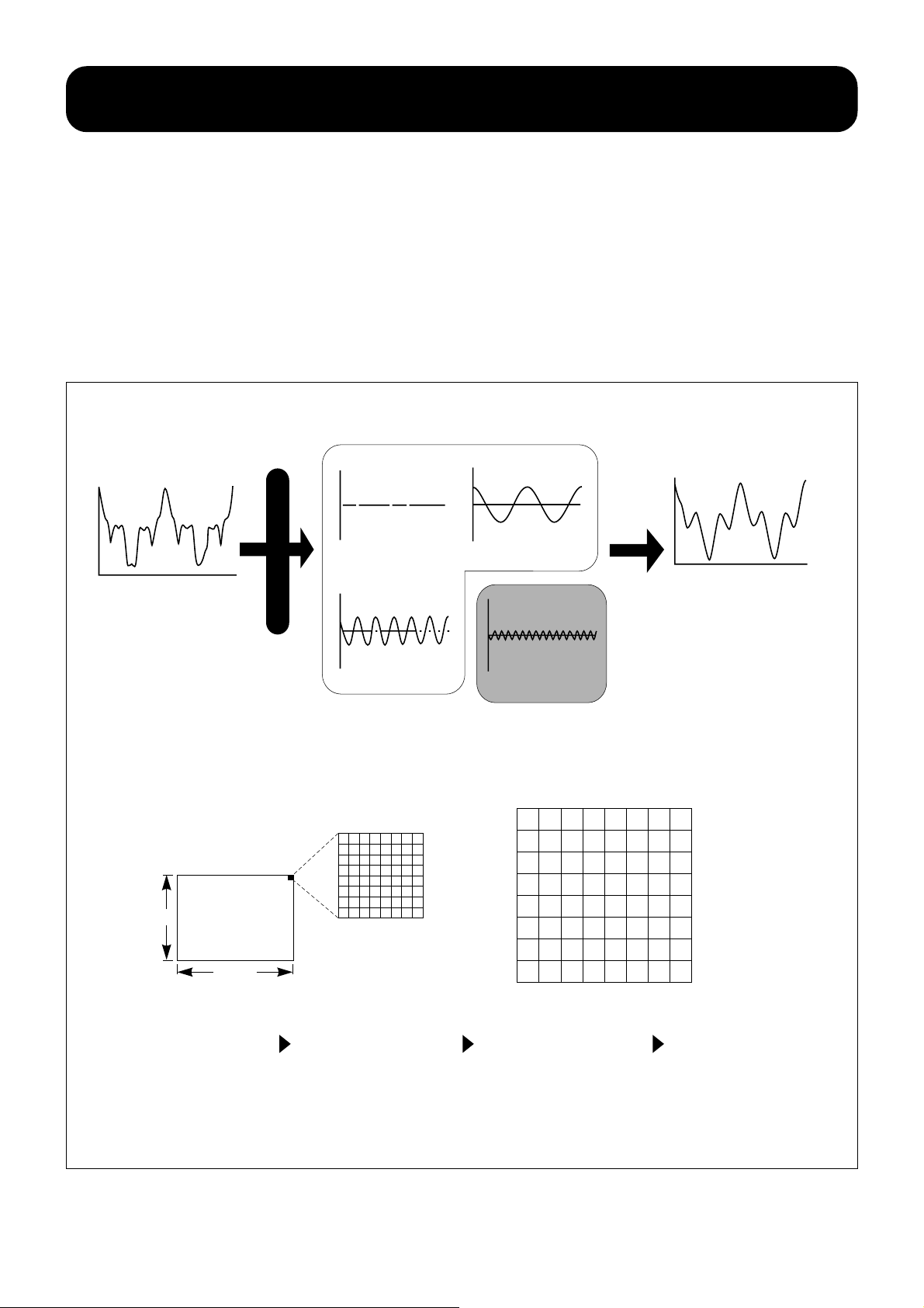
■DCT removes unnoticeable frequency elements.
The nature of human perception is deeply considered in
the compression of data for both video and audio.
Human vision perceives pictures with some of high
frequency elements omitted the same as pictures
without any omissions. The total data is reduced by
omitting unnoticeable frequency elements selectively
after picture signals are resolved in several frequency
element groups. The frequency element resolving
process of MPEG2 (and MPEG1 is basically the same) is
■Basic concept of spatial axis compression
frequency A
original wave form
resolution
called the “Discrete Cosine Transform” method and
selective omission of specified frequency elements
taking advantage of limitations in human perception is
called the “Quantize Matrix” method. These processes
are done with dividing a frame of the picture in blocks of
8 x 8 elements (6480 blocks in total) and the luminance
levels of the elements in each block are converted into
values, and then are converted into frequency element
data.
frequency B
freq A + freq B + freq C
frequency C
■Encoding process for spatial axis compression
one frame is
576 elements
Changes in luminance and color
are small in some parts of a
frame (low frequency) while
changes are large in other parts
(high frequency) and a frame
can be considered as an
overlaid composite picture
comprised of a very low
frequency picture, a low
frequency picture, a high
frequency picture, and a very
high frequency picture.
divided into
6480 blocks.
720 dots
one frame is
divided in
blocks of 8 x 8
elements.
One frame is divided into
small blocks, and luminance
and color values of picture
elements in each block are
converted into numerical
data. Then, the data is
converted by DCT into an 8 x
8 block of frequency data.
frequency D
(high frequency elements)
removed selectively
10
5
1
0
0
5
0
0
0
0
0
0
0
0
0
0
0
0
0
0
0
0
0
0
0
0
0
0
0
0
0
0
0
0
0
0
0
0
0
0
Larger picture element values,
distributed at random before
the DCT conversion, tend to
gather in low frequencies
region (upper left area of the
block) by the DCT conversion.
0
0
0
0
0
0
0
0
0
0
0
0
0
0
0
0
0
0
0
0
0
0
0
0
Values after conversion are
divided by a specific number
and the remainders are
rounded (quantization step)
to get many 0s line up in
higher frequency regions
(lower right area of the block).
Removing these zeros (higher
frequencies region)
compresses the total data.
20
Page 22

Time axis compression -
predictive coding with motion compensation
■Predictive cording constructs image by predicting motion from preceding and
succeeding pictures
An image in PAL television and video is composed of 25
synthesizing with the differential to reproduce pictures.
frames/second (a frame consists of 625 scanning lines)
and the display equipment reproduces a picture of 50
fields/second since it is scanned by interlacing to
eliminate flickering. A large part of each picture is made
of the same elements if continuous 25 pictures per
second are compared with each other. And, they do not
change much in a short time.
The method to reconstruct the original picture by
extracting and coding the differential between
continuous pictures is called “Predictive Coding”
because the current picture is predicted from the picture
immediately preceding it. As described in detail in the
following section, “Time axis compression, GOP
construction and bi-directional prediction, ”MPEG
If there is a changing part in 25 pictures, the data
volume necessary to store and reproduce the picture will
be much smaller if only the changed part (differential) is
provides the coding to predict the current picture from
the immediately preceding and succeeding pictures on a
bi-directional prediction.
stored and the other part is stored for one picture for
■Motion Compensation extracts only motion changes
There are two types of changing parts or parts with
motion in pictures: one does not change its shape but
changes its position as time elapses, while the other
changes its shape as time elapses. Data of the shape
should be used as it is for the former. The amount of
position change without changing shape which takes
place with time, or the amount of movement, is called
the “motion vector.” The original picture can be
reconstructed when reproduced (in the decoding
process) with smaller data volume by coding only the
movement. This method which uses the motion vector is
■Predictive coding and motion compensation
(1)
(1)—(2)
(2)
1. Pictures (1) and (2) to be reproduced as time elapses
have many elements common to each other.
Differential or (1) minus (2) is extracted and (2) is
reproduced by synthesizing the differential with (1).
Preceding frame
Current frame
The
position
in the
The
position
in the
2. In the motion compensation process, pictures
are divided into blocks and the motion vector
which indicates the amount of movement is
extracted and coded for the part whose
position changes, without changing its shape.
By combining this motion compensation with
predictive coding, data is more efficiently
compressed.
21
Page 23
Time axis compression -
GOP construction and bi-directional prediction
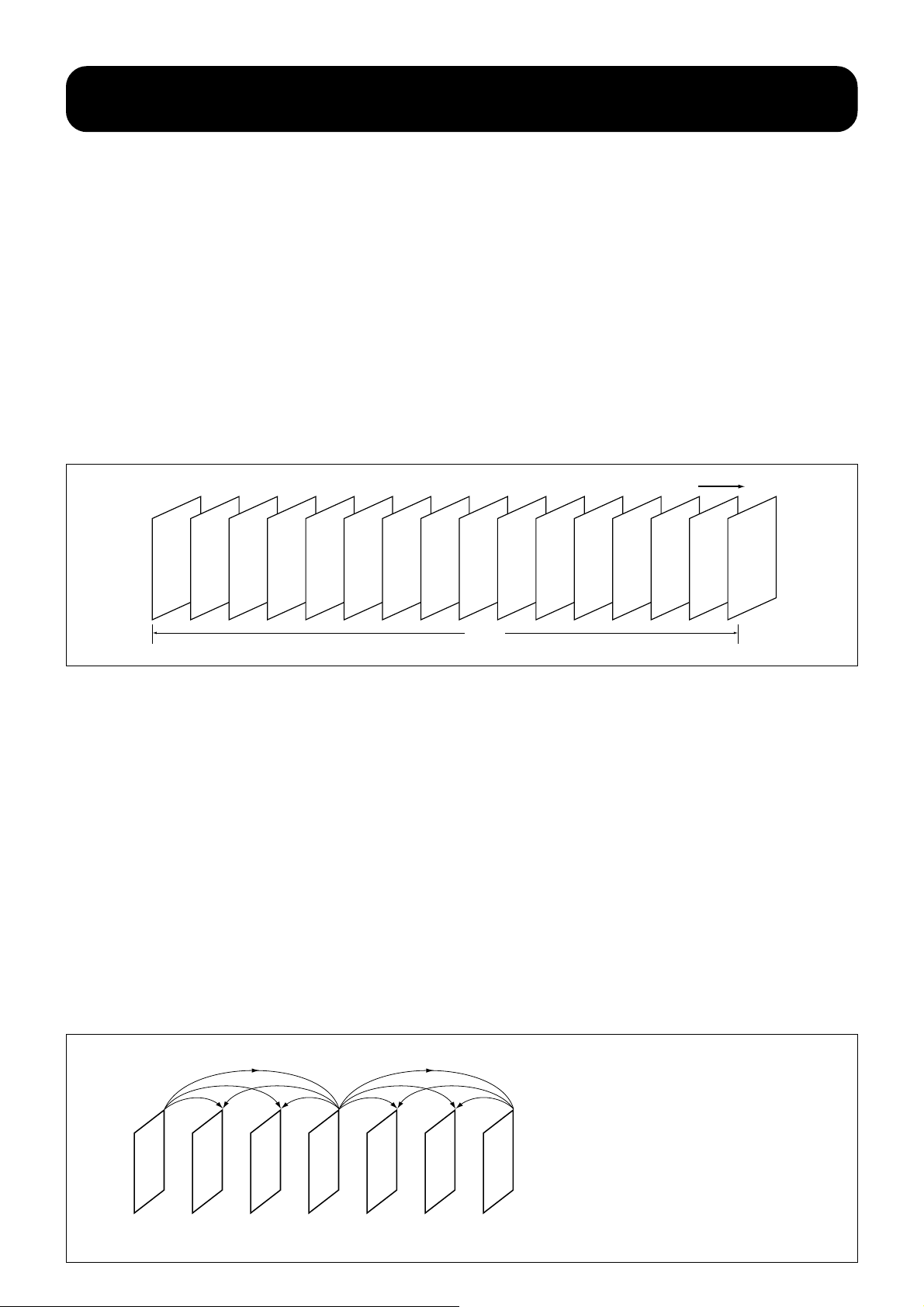
■GOP construction by I picture, P picture, and B picture
To perform predictive coding employing motion
compensation, MPEG2 uses GOP (group of pictures)
construction made of three elements called the I picture,
P picture, and B picture and MPEG2 organizes roughly
15 consecutive video frames into GOPs. The I picture
(Intracoded picture) is compressed by DCT using
information within the frame only without predicting the
motion from the preceding frame.
If pictures constructed by the predictive coding are
successively lined up, pictures cannot be displayed
instantly when accessed at random. Then, the standard
for access is made periodically to respond to random
accessing. The I picture is for maintaining independence
from the GOP, so to speak.
The frequency of the I picture is normally 1-I picture/ 15
frames it is decided based upon the random access
capability required for applications. The data volume of
an I picture is 2 to 3 times that of the P picture and 5 to
6 times that of the B picture. The GOP is the group of
pictures from one I picture to the next I picture. Thus, in
simple terms, picture prediction is performed within
pictures in the same group.
■An example of picture arrangement in GOP
.... I
B B P B B P B B P B B P B B I ....
GOP
I picture = Intracoded picture P picture = Predictive coded picture B picture = Bi-directionally predictive coded picture
Time
■The P picture and B picture
The P picture (predictive coded picture) is made on
the basis of the I picture by predictively encoding the
immediately preceding picture. The P picture may be
defined as an “interframe forward direction predictive
coded picture” in relation to the I picture, which itself
is an “intraframe coded picture.” The B picture is a
“bi-directional predictive coded picture” and is made
by predicting two P pictures, the preceding and the
succeeding. Taking a close look at the relationship
between the I picture, P picture, and B picture in a
GOP, the first step prediction made from the I picture
located at the beginning of the GOP is performed in
the forward direction and the P pictures are made. At
that time, the P pictures are positioned jumping over
■Forward and bi-directional
a multiple number of B pictures to be constructed
later.
A multiple number of B pictures are made by the second
step prediction from the first I picture and the P picture
coded at the first step prediction (bi-directional
prediction) and they are positioned between the I picture
and the P picture. Another set of B pictures is made
between the first P picture and the second P picture.
The B picture when decoded compensates motion
using two motion vectors and two reference pictures,
preceding and succeeding. Bi-directional prediction, a
feature of MPEG, uses two pictures, the past and future
pictures timewise, for prediction to achieve highly
efficient prediction.
22
IBBP
bi-directional
prediction
forward
prediction
B
BP
The P picture is constructed by forward predicting
the immediately preceding I picture or P picture
while the B picture is made by bi-directional
prediction using the immediately preceding and
succeeding pictures.
Page 24

Huffman coding
■Huffman coding: a statistical method for data compression
In addition to motion compensation, which removes data
redundancy using correlations of the time axis in
pictures, and DCT which removes data redundancy
employing correlations of spatial axis in pictures, MPEG2
(MPEG1 is basically the same) uses a method called
Huffman coding to achieve a further reduction in data
redundancy.
Huffman coding uses correlation in the code row made
by MPEG processing to compress data (for example, five
Questions & Answers
What is 4:2:0 coding in MP@ML?
In MP@ML (Main Profile at Main Level) of MPEG2, a
component system called “4:2:0” is adopted for
encoding video signals. Numbers 4, 2, and 0
indicate the sampling frequency ratio of the
luminance signal (Y) and two color differential
signals (Cb and Cr) included in the horizontal
scanning lines of video pictures, or the resolution
ratio. For one picture element [Note 1], 8 bits are
used for luminance and 8 bits each are used for
color differential. The eye is not so sensitive to color
as it is to luminance, and because the human eye is
unable to perceive the reduction of color information
as picture quality degradation in relation to
luminance information, data can be compressed
with no perceivable visual difference.
Pictures without color information reduction are
called “4:4:4,” pictures reduced to half in the
horizontal direction called “4:2:2,” and pictures
reduced to half in both the horizontal and vertical
directions are called “4:2:0.” In the “4:2:0”system,
color information is one fourth of luminance
consecutive 0s are expressed as 0 x 5 instead of lining
up five 0s). This may be called a “statistical” method if
the motion compensation is called a “time” method and
DCT a “spatial” method. Picture data is compressed
spatially, statistically, and chronologically in MPEG2 and
the total volume of codes generated is controlled by the
quantization step for efficient data transmission.
information. The DV system, which has achieved
excellent color reproduction for home use digital
video, employs a “4:1:1” type component signal
system that reduces color information to one fourth
of luminance information and its data volume is the
same as the “4:2:0” of the MP@ML of MPEG2. The
“4:2:0” [Note 2] coding system is normally
processed and output as “4:2:2” after lines are
supplemented by processing within the LSI.
Note 1: In MPEG2, 8 bits are used for each of
luminance Y, and color differential Cb and Cr in one
picture element (3 X 8 = 24 bits).
Note 2: The sampling frequency for all of Y, Cb, and
Cr is 13.5 MHz in “4:4:4.” In “4:2:2”, 13.5 MHz for
Y, 6.75 MHz for Cb and Cr. In “4:1:1”, 13.5 MHz for
Y, 3.375 MHz for Cb and Cr. In ”4:2:0”, 2 lines with
different sampling rates are alternatively repeated.
One is 13.5 MHz for Y, 6.75 MHz for Cb and Cr is
not sampled, while the other is 13.5 MHz for Y, Cb
23
Page 25

Are there any differences between DV and DVD data compression?
The DV format of digital video recording is available
as home use video media. It is quite different from
DVD-Video in terms of compression because of the
basic physical difference between the two forms of
media, magnetic tape and optical disc. Moreover,
the DV format uses only “within picture correlation’’
compression while DVD employs both ”within
picture correlation” and “time axis correlation”
compression.
What is the reason for this? DV was designed from
the very beginning as a means to provide video
recording and playback in the home, so tape editing
at any point is as an important requisite as
recording and playback. Data compressed on the
time axis has to be decompressed each time it is
played back or edited and data must be re-
compressed on the time axis to keep the data on
the tape. This requires tremendous signal
processing power, and is very inefficient.
For this reason, taking advantage of the far larger
storage capacity of tape over disc,“ within picture
compression” is used in DV for compressing data
on the tape while DVD must also rely on “time axis
compression” because of capacity limitations.
In addition to DVD, MPEG2 can also be applied in
digital TV broadcasting, and is expected to be
advantageous in multi-channel broadcasting. To
make this possible, the bandwidth per channel
must be kept as narrow as possible, so time axis
compression will be employed.
24
Page 26
Bit rate technology in DVD-Video (2)
variable transmission rate
■Variable bit rate allows highly efficient image storage
The bit rate is the data volume which can be sent in a
unit of time and is expressed by the number of bits sent
in a second (bps=bits per second). The larger the rate is,
the greater amount of data can be transmitted, and this
(generally) results in higher image and sound quality. In
compressing pictures by MPEG2, a bit rate of about 6
Mbps is required to maintain the same picture quality as
PAL television broadcasting.
However, quick-motion parts of pictures require more
data, so a higher bit rate is required to maintain high
picture quality. On the other hand, parts of pictures with
virtually no motion or almost still pictures require much
less data, so high picture quality can be maintained with
a lower bit rate.
The problem which arises here is the relationship between
the bit rate and recording time. To maintain high picture
quality regardless of the condition of the pictures, the
highest bit rate fitted for picture parts which require the
largest data volume may be used. Since the data capacity
of the disc equals the bit rate times the recording time,
the higher the bit rate, the shorter the recording time. A lot
of data is wasted if the actual data volume needed for
pictures is small.
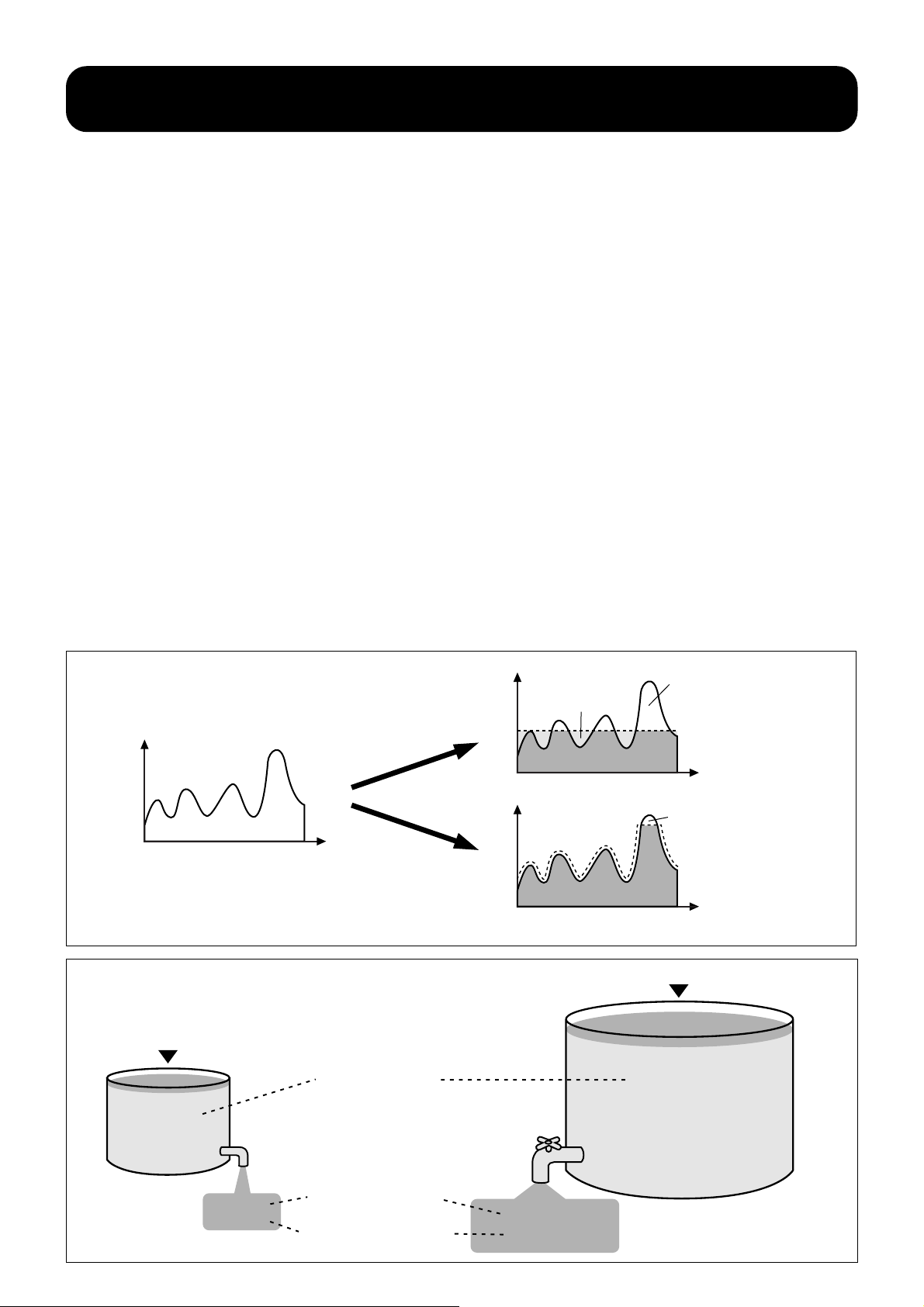
A variable bit rate technology with a maximum speed of
9.8 Mbps is employed in DVD-Video to eliminate
wasteful data allocation. The bit rate is varied according
to conditions of pictures; a high bit rate is used for parts
of pictures which require a large data volume, while a
lower rate is used for parts which require small data
volume in order to make more efficient use of data
capacity. With a variable bit rate, an average bit rate of
3.5 Mbps is accomplished in DVD-Video. If a fixed bit
rate were to be used, the rate will need to be two times
the variable bit rate just to maintain the same picture
quality.
Incidentally, Video CD which compresses images with
MPEG1 technology uses a fixed rate of 1.15 Mbps. This
is one of the most significant technical differences
between it and DVD-Video.
■Fixed or Variable transmission rate
amount of information
elapsed time
fixed bit rate
compression
variable bit
rate compression
■Transmission rates of Video CD and DVD-Video
●Video CD, recorded at
fixed 1.15 Mbps rate
tank capacity
(disc storage capacity)
amount of information
amount of information
●higher transmission rate must be set to obtain high
impossible
wasted
elapsed time
impossible
a little waste and impossible
elapsed time
picture quality if transmitted by the fixed rate
●DVD-Video, recorded at maximum of 9.8 Mbps without waste
4.7GB
0.68GB
1.15 Mbps,
fixed bit rate
(1Mbps=1Mega bps=1 ,000,000bps)
faucet without
a stopcock
Whether or not the faucet has a
stopcock for adjusting water flow
(Can transmission rate be changed?)
amount of water drained in
aminute (transmission rate)
Faucet with
a stopcock
Max 9.8 Mbps,
variable bit rate
The more a stopcock is turned (transmission
rate is increased), the more water is drained
(more data is sent) and time required to empty
tank (recording time) will be short.
25
Page 27

DVD-Video’s superb audio capabilities
Non-compressed linear PCM audio, Dolby Digital, and
MPEG Audio are adopted (along with other systems) for
their superb audio quality to match the high image quality
of the DVD-Video system. In DVD-Video, a maximum of
eight streams (refer to page 31) are available for
soundtrack recording.
It is mandatory that a mono or stereo
soundtrack is used as either one pair of
linear PCM audio tracks, or as Dolby
Digital or MPEG Audio for discs and
players in connection with a 625/50 (PAL/
SECAM) TV system. For 525/60 (NTSC) TV
systems, Linear PCM or Dolby Digital is used. In addition,
either Dolby Digital or MPEG multi-channel soundtracks
can be used as an option with PAL/SECAM TV systems,
while MPEG is an option with 525/60 NTSC TV systems.
Furthermore, Dts and the SDDS 7.1 channel digital
surround system developed by Sony are standardized in
the format, and are available as options.
Compressed multi-channel audio formats, such as Dolby
Digital and MPEG-2, can carry a multi-channel
soundtrack compressed into a single stream of digital
data. There are various configurations of multi-channel
audio to go with moving video images. The most
common is 5.1, which supplies separate sound channels
to the left (L), center (C) and right (R) front speakers, as
well as the left and right (Ls and Rs) surround speakers,
along with low-frequency effects (LFE) to the subwoofer,
which is known as the “.1” channel.
■
Speaker layout for 5.1 channel
L ch
C ch
Front speakers
R ch
LFE
The number and quality of these audio tracks, which are
variously applied in DVD software, is left to the discretion
of the producers, who should retain the right to determine
the contents of their software. Accordingly, this multiple
track potential makes it possible to dub movie software
with several different languages.
Ls ch Rs ch
Surround speakers
26
Page 28

DVD-Video’s high fidelity (1) - Dolby Digital
■Various Dolby Digital (AC-3) modes
channel format
audio coding mode
LCR L R
1/0
2/0
3/0
2/1
3/1
2/2
3/2
Surround modes other than 2 channel are available.
■Bringing the appealing power of the theater home with Dolby
front surround
monaural
monaural
monaural
stereo
surround
The Dolby Digital (AC-3) system, already popular in some
Laserdisc software, makes 5.1 channel high quality
surround reproduction with its theater-like presence
possible in the home. It is considered the main audio
system for the DVD-Video pre-recorded movie software.
Dolby Digital (AC-3) was initially put into use in 1992 as a
digital surround system called the Dolby SR-D system for
theaters, and is used in major movies produced in
Hollywood. Using the Dolby Digital (AC-3) system, sound
■Full-band 5.1 channel surround
The Dolby Digital (AC-3) system is a high quality digital
sound system equipped with a channel dedicated to
subwoofer output (LFE=Low Frequency Effect) in order
to reproduce low frequencies below 120 Hz in addition
to the front left, front right, front center, surround left,
and surround right channels. The conventional Dolby
Pro Logic system converts two track signals into four
channels (front left, right, center, and surround) at the
decoding stage by using an analog matrix process. In
the Dolby Digital system, each channel is discretely and
digitally processed from the beginning, so they are
independent and contribute to excellent channel
separation. Even surround sound comes in stereo and
all five channels are reproduced at full bandwidth (3 Hz 20 kHz).
With these features, movie producers are able to
reproduce sound accurately in the home theater context
with the intended positioning of the sound image and
the feeling of soundstage movement, along with
surround reproduction with presence and power
of DVD-Video can be recorded in many selectable
channel modes depending on the contents of the
software. Monaural, 2-channel stereo, 3-channel
surround, and 4-channel surround, and even 5.1-channel
surround can be selected. Dolby Digital (AC-3) is
equipped with dynamic range control which controls
sound peaks in order to maintain the dialog at an audible
level when watching a movie very late at night or in other
comparable to the movie theater experience.
DVD-Video players equipped with Dolby Digital have
decoders capable of performing the sound mix-down for
playback by decoding the 5.1 channel surround sound
in the Dolby Pro Logic signals and two channel stereo
signals. In players without Dolby Digital, conventional
surround and stereo playback are performed upon
playback of DVD-Video software.
■Home surround system comparison
surround system
number of recording
channels(source)
number of playback
channels
playback channel
configuration
sound processing
bandwidth of
surround sound
Dolby Digital (AC-3)
5.1ch
5.1ch
front L/C/R,
surround L/R,
subwoofer
digital discrete
processing
3Hz~20kHz
Dolby Pro Logic
2ch
4ch
front L/C/R, surround
(mono), subwoofer
recommended
analog matrix
processing
~7kHz
27
Page 29
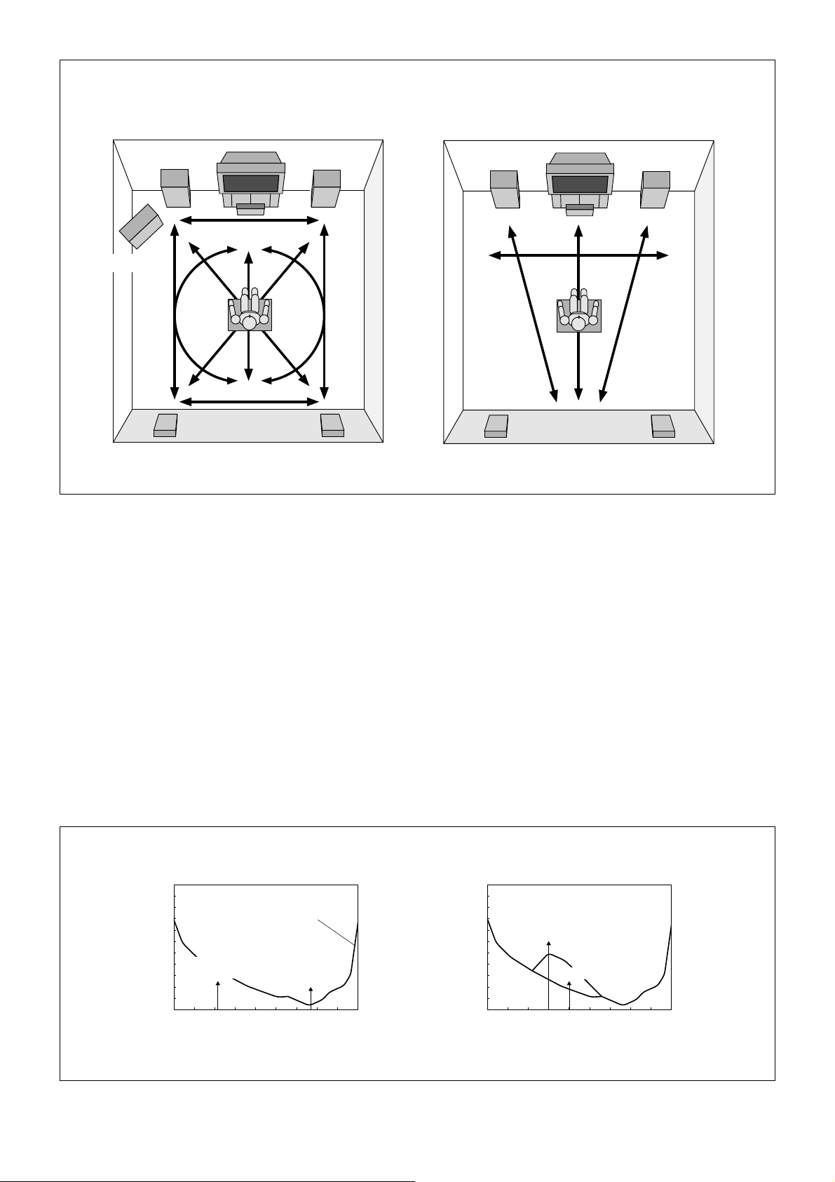
■Effect of 5.1 channel surround sound
5.1 channel surround sound by Dolby Digital (AC-3)
front speaker (left)
subwoofer
(below 120 Hz)
rear speaker (left)
surround sound is also in stereo with high fidelity at
full bandwidth (3 Hz to 20 kHz)
center speaker
front speaker (right)
rear speaker (right)
conventional Dolby Pro Logic surround
front speaker (left) front speaker (right)
rear speaker (monaural)
surround sound is monaural and response is only up to 7 kHz
center speaker
rear speaker (monaural)
■High efficiency coding method of Dolby Digital AC-3
The “AC” in the name Dolby Digital AC-3 stands for
Audio Coding and AC-3 is the highly efficient thirdgeneration coding system following AC-1 and AC-2.
One of its major features is the unified coding of multichannel sound. This is made possible by processing
multi-channel data together through a unique program
called “Global Bit Distribution.”
In coding the data; (1) low level low frequency sound
and low level high frequency sounds not audible by the
human ear owing to its frequency limitations, (2) low level
sound not audible by the masking effect due to
differences in sound level, and (3) low level sound not
■Examples of inaudible sound contained in audio data
●low level sound in the inaudible range
100
80
60
sound level
40
inaudible unless
sound is higher level
20
0
20 50 100 200 500 1k 2k 5k 10k 20k
Human hearing is most sensitive at or around 4 kHz
and sound, as its frequency goes above or below 4
kHz, becomes harder to perceive.
audible sound
pressure level curve
audible even
when sound
level is low
frequency (Hz)
audible by the masking effect between channels, are all
deleted and the data is sampled after it is divided into 50
uneven bandwidths configured based on the
“logarithmic” nature of human auditory sensitivity.
The method used to delete (1) and (2) is similar to that
used in ATRAC (Adaptive Transform Acoustic Coding), a
compression system employed in the MiniDisc format.
Deleting unnecessary details of information by taking
advantage of the characteristics of human audio
perception is called “perceptive coding.” For your
reference, the 5.1 channel surround sound transmission
rate in DVD-Video is 384 kbps in total.
●sound masked by higher level sounds
100
80
60
sound level
40
20
0
Low level sound near high level sound becomes
inaudible
high level sound
low level sound (inaudible)
20 50 100 200 500 1k 2k 5k 10k 20k
frequency (Hz)
28
Page 30

DVD-Video’s high fidelity (2) -
MPEG Audio
When a DVD-Video disc in the PAL/SECAM format has
audio content, it must have at least one stream of either
MPEG Audio, Dolby Digital or linear PCM audio.
■Multi-channel surround system
MPEG Audio is compressed digital audio supporting
from one to eight channel combinations, and shown in
the accompanying chart. The LFE channel is optional in
all combinations. For wider viewing angles, the optional
7.1 channel sound coding adds left-center and rightcenter channels.
■MPEG Audio Modes
MPEG-1 modes Multi-channel output
1/ 0 mono
2/0 stereo
MPEG-2 modes
3/0 stereo with center channel
2/1 surround - two front channels and mono surround
3/1 surround - three front channels and mono surround
2/2 surround - two front channels and stereo surround
3/2 surround - three front channels and stereo surround
5/2 surround - five front channels and stereo surround
■Speaker layout for 7.1 channel MPEG-2
L ch LC ch
C ch RC ch
Front speakers
R ch
LFE
Ls ch Rs ch
Surround speakers
■Features of the MPEG Audio System
MPEG-2 is a compatible surround system, and an
extension of the MPEG-1 audio format. For reproduction
of 5.1 multi-channel sound, additional information is
necessary in the first extension part of the MPEG bit
stream. And, for reproduction of full 7.1 multi-channel
sound, more additional information is necessary in the
second extension part of the MPEG bit stream. A DVD
player having only stereo MPEG playback capability can
extract the MPEG-1 compatible stereo audio content
from the MPEG-2 audio stream on the disc.
Another feature of MPEG Audio is that it can be
recorded on the disc at a constant or a variable bit rate.
Constant bit rates can be set between 64 k and 912 k
bits per second. For the variable bit rate option in MPEG
Audio, an average bit rate can be selected to meet the
quality, capacity and transfer rate requirements for
sound encoding. When the audio material is less
complex, the actual bit rate necessary to maintain the
required level of audio quality can be specified.
Compared with constant rate encoding, variable bit rate
MPEG-2 encoding can offer audio data capacity and
transfer rate savings of between 25 to 33%.
In this way, the advantages of MPEG Audio can be
applied in a number of digital audio and video
distribution applications, such as DVB, DAB, CATV, CDROM, Video CD, telecommunications uses, and more.
■MPEG Audio’s high efficiency coding method
MPEG Audio is a high quality and highly efficient form of
audio coding to ISO/IEC standards. In MPEG Audio
compression, perceptual coding plays an important role.
Studies in psychoacoustics have shown that low level
sounds and the low and high frequency ranges are not
audible due to the perceptory limitations of the human
ear. This concept, along with the concept of “masking”
are used to take full advantage of psychoacoustic
principles. A total of 32 bands of sub-band coding,
along with Modified Discrete Cosine Transform
operation, is used along with other forms of coding. As a
result, highly efficient compression is achieved with
29
Page 31

DVD-Video’s high fidelity (3) -
Linear PCM
■Linear PCM delivers the highest level of sound quality
The most important feature of linear PCM is that it
delivers the highest level of sound quality since it does
not employ data compression. Accordingly, it has been
adopted in the DVD-Video system. Either 16-bit, 20 bit
or 24-bit quantization rates can be used with 48 kHz or
96 kHz sampling rates, in any combination, can be used
in linear PCM. The maximum bit rate is set at 6.75 Mbps
per stream, and within this range up to eight channels of
audio can be recorded, as a standard option. When
using higher bit rates and the higher sampling frequency,
of course, the number of channels which can be used
are reduced, but at 16-bits/48 kHz, a full eight channels
can be used. Music video software can be enjoyed with
high-fidelity surround sound reproduction, a feature
■Linear PCM audio specifications
sampling frequency quantization bit max. number of channels (and bit rate)*
16-bit 8ch (6.144 Mbps)
48KHz 20-bit 6ch (5.760 Mbps)
24-bit 5ch (5.760 Mbps)
16-bit 4ch (6.144 Mbps)
96KHz 20-bit 3ch (5.760 Mbps)
24-bit 2ch (4.608 Mbps)
*Per stream; maximum bit rate per stream is 6.75 Mbps.
30
Multiple-language function
■Multiple-language dubbing of up to eight languages
DVD-Video is capable of recording up to eight streams
of sound, with either the Dolby Digital system, the MPEG
Audio system or the linear PCM system selectable for
each stream within data capacity limitations. As in some
movie software, each stream is used for dubbing a
different language, and a particular stream can be
selected from the menu upon playback. This multi-
■Multiple-language subtitling of up to 32 languages
DVD-Video is also capable of storing subtitles in up to
32 different languages, and any language can be
selected from the menu for display upon playback. Any
combination with a soundtrack language selected in the
multiple-language dubbing function is possible. The
remote controller of a DVD-Video player controls the
display of subtitles, so subtitles may be displayed or
removed from the screen at any time and software can
be used in the same way as the software with closed
captions which was not only used by the hearing
impaired, but also popular for language learning. The
“sub-picture” function of DVD-Video is used for the
multiple-language subtitle function, and DVD-Video has
32 streams for these sub-pictures. Besides subtitles for
language dubbing feature allows the creation of up to
eight different soundtracks. Needless to say, playback
through the Dolby Digital or the MPEG Audio 5.1
channel surround sound is also possible. Using the
same movie software, one language may be selected
when viewing alone, while another can be selected
when viewing with others.
movie software, the sub-pictures can be applied in many
different and interesting ways, as the accompanying
chart shows.
■Examples of sub-picture applications
menu
movies
karaoke
games
text (changing displayed color, fade in, fade out)
may be combined with main pictures
(moving pictures and still pictures)
used with highlight commands
subtitles (multiple-language, scrolling)
timing display
(changing displayed position, flashing)
used with highlight commands
Page 32
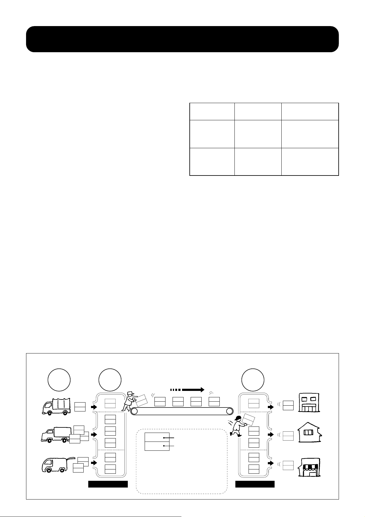
Stream and packet transmission
■“Stream” data flow
When speaking of data to be stored, there is the basic
concept called the “stream” in DVD-Video. Literally, this
means a data flow and it may be imagined as something
similar to a track on a tape recorder.
Audio data or video data is stored on a stream and the
data is retrieved from the stream for playback. The number
of streams available in DVD-Video are one stream for the
video (main pictures), eight streams for audio, and 32
streams for sub-pictures. Tracks on tape used for analog
recording are arranged parallel to each other lengthwise,
while data stored on a DVD disc are a tremendous number
of pits stretched in a row. Picture data, audio data, and
■Transmission by packet multiplexing
Data is stored by the “packet multiplexing” system on the
DVD disc. Packet multiplexing is a system in which video
data and audio data are arranged into a number of blocks
called “packets” and they are tagged with packet headers
which indicate data type, stream number, and time axis
information in a multiplexed (time division multiplexing)
method.
The time division multiplexing is much
like what happens to packaging and shipping fruits in a
warehouse. Various kinds of fruit (data) which farmers
have brought in are classified by type and packed in the
standard-sized cartons (packets) in the center. Tags are
put on cartons to indicate contents and destinations and
all cartons are placed and carried by a conveyor belt
system. This can be compared to the row of many pits
recorded on a disc.
other data are included in this pit row. Let’s take a look at
how these forms of data are retrieved from the pit row.
■Outline of the DVD-Video data stream
video data 1 stream MPEG2 system
linear PCM, Dolby
audio data
subpicture data
8 streams, max
32 streams, max
(subtitles, etc.)
The market receives and classifies cartons by tags and
delivers them to stores and to consumers. Multiplexing
various coded data rows corresponds to the placing of
cartons containing different kinds of fruit on a conveyor belt
and moved one after another. A circuit which performs a
similar process is called the “Multiplexer (MUX)”.
Separating multiplexed data (multiplexed streams) in
original data rows may be regarded as equivalent to
separating cartons by the kind of fruit at the market, and a
circuit which performs this task is called the “Demultiplexer
(DMUX)”.
The volume of coded picture data in DVD-Video varies by
frame, so video and audio cannot be synchronized by
simple separation and compounding. Actually, a very
complex process is performed to synchronize picture data
and audio data in DVD-Video packet transmission.
Digital (AC-3), or
MPEG Audio
run length coded
bit map
■Data transmission of streams by packet multiplexing
agricultural
farmers
(video)
(audio)
(subpictures)
(processed at authoring)
cooperative
association
M
ultiplex
V
60
A-1
80
A-2
70
A-3
70
S-1
50
S-2
45
V
V
40
(status of data on the disc)
V
40
type (no. of streams)
V=video data
A=audio data (8 max.)
S=subpicture data (32 max.)
A-260S-145S-2
20
type + number of
streams
time axis information of
packets
market
30
A-1
40
Demultiplexing
(processed in the player)
15
A-2
35
A-3
60
S-1
25
S-2
15
V
V
10
A-3
40
S-1
15
(subpictures)
(video)
(audio)
31
Page 33
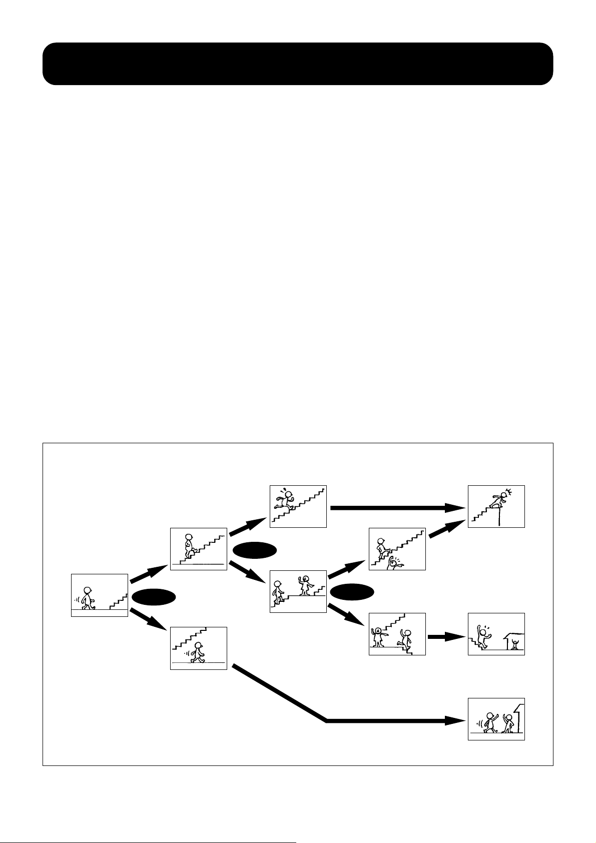
DVD-Video interactive operation
Random access functioning is a feature common to
optical disc media. DVD-Video makes full use of this
feature and new functions for the new generation of
video media such as multi-story and multi-angle
functioning are incorporated in the DVD-Video, enabling
■Title menu and DVD menu
The DVD-Video can contain the title menu coupled with
DVD “sub-picture” function. So producers can create a
“Visual table of contents”, enabling viewers to choose
sections and access them directly. For example, a music
video disc might have a little menu of songs. A movie
disc might have a menu of chapters, identified by
■Multi-story function
The multi-story function allows the recording of a
number of different story sequences on the disc.
Viewers can select story development during playback
from the displayed menu. Highly interactive software can
be created depending on software producers’ ideas by
making use of the large storage capacity of DVD.
the creation of highly interactive software. Instead of
passively watching discs straight through, viewers can
get involved, engrossed with multiple story lines, multiple
camera angles and more.
representative pictures. DVD menu allows a choice of
audio formats, sound tracks and subtitle languages, can
also be programmed onto a disc. Disc producers are
free to design their own menus, according to the type of
software.
The multi-story function allows the recording of a
number of program chains composed of picture and
audio data matched to story configurations with control
commands on the disc. The desired playback sequence
is achieved by linking information in response to the
menu or the viewers’ operation.
■Multi-story function (concept)
menu
selection
menu
selection
menu
selection
Story A
Story B
Story
C
32
Page 34
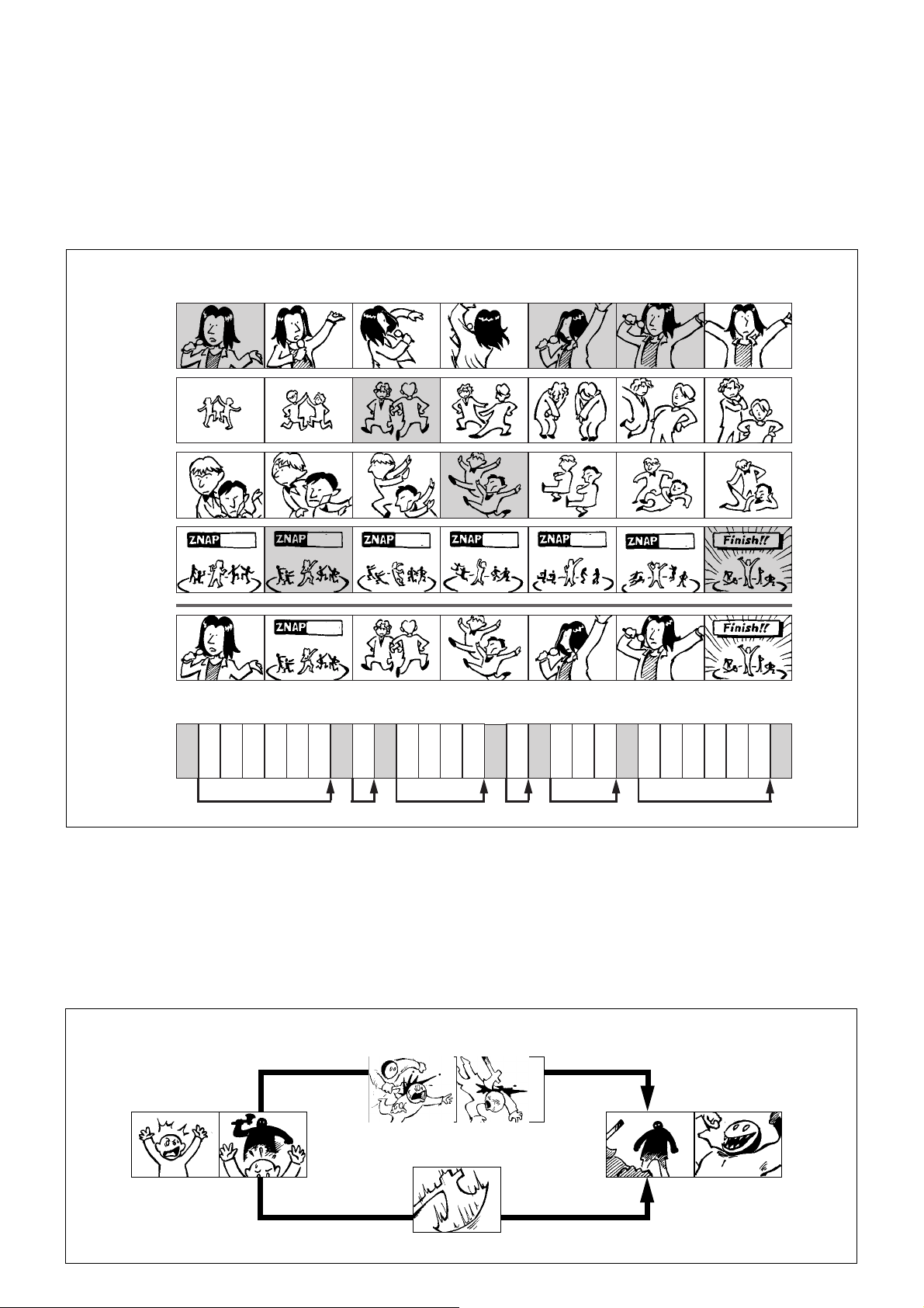
■Multi-angle functioning up to nine angles
Video scenes taken from up to nine different camera
angles can be stored on a disc in DVD-Video, and during
playback the desired angles can be selected instantly by
the multi-angle function. For example, in live concert
software, an individual member such as a vocalist or a
guitarist may be taken by a camera in addition to the
entire stage picture.
■The multi-angle function (concept)
1
234567
camera
A
camera
B
camera
C
camera
concert concert
concert
D
A level of “custom” software enjoyment not possible with
conventional media is easily achieved with DVD Video if
so created at the software production stage.
A remarkable feature of the multi-angle function is its
ability to reproduce a scene without a break from a
number of scenes which are progressing simultaneously.
This capability is called “seamless playback.”
concertconcert
concert
reproduced
scene
concert
A-1 D-2 B-3 C-4 A-5 A-6 D-7
locations of
reproduced
data on a disc
B
C
D
A
B
C
D
A
B
C
D
A
-
-
-
-
-
-
-
-
-
-
1
1
1
1
2
2
2
2
3
3
jump jump jumpjump jump jump
A
-
-
-
3
3
4
■Parental lock function (optional standard)
A function called “parental lock” allows the “locking” of
software at the discretion of parents to prevent
undesired viewing by children depending on contents of
software. Normal reproduction of the disc with this type
of software requires a registered identification code and
■The parental lock function (concept)
scene for adults
A
B
C
D
A
B
C
D
A
B
C
B
D
C
-
-
-
-
-
-
-
-
-
-
-
5
5
5
5
6
4
4
4
6
-
6
6
7
D
-
-
-
7
7
7
otherwise undesirable (from an educational or other
standpoint) scenes such as violence are automatically
skipped or switched to an alternate scene recorded on
the disc. The parental lock function is an optional
standard using the seamless playback capability.
scene for children
33
Page 35
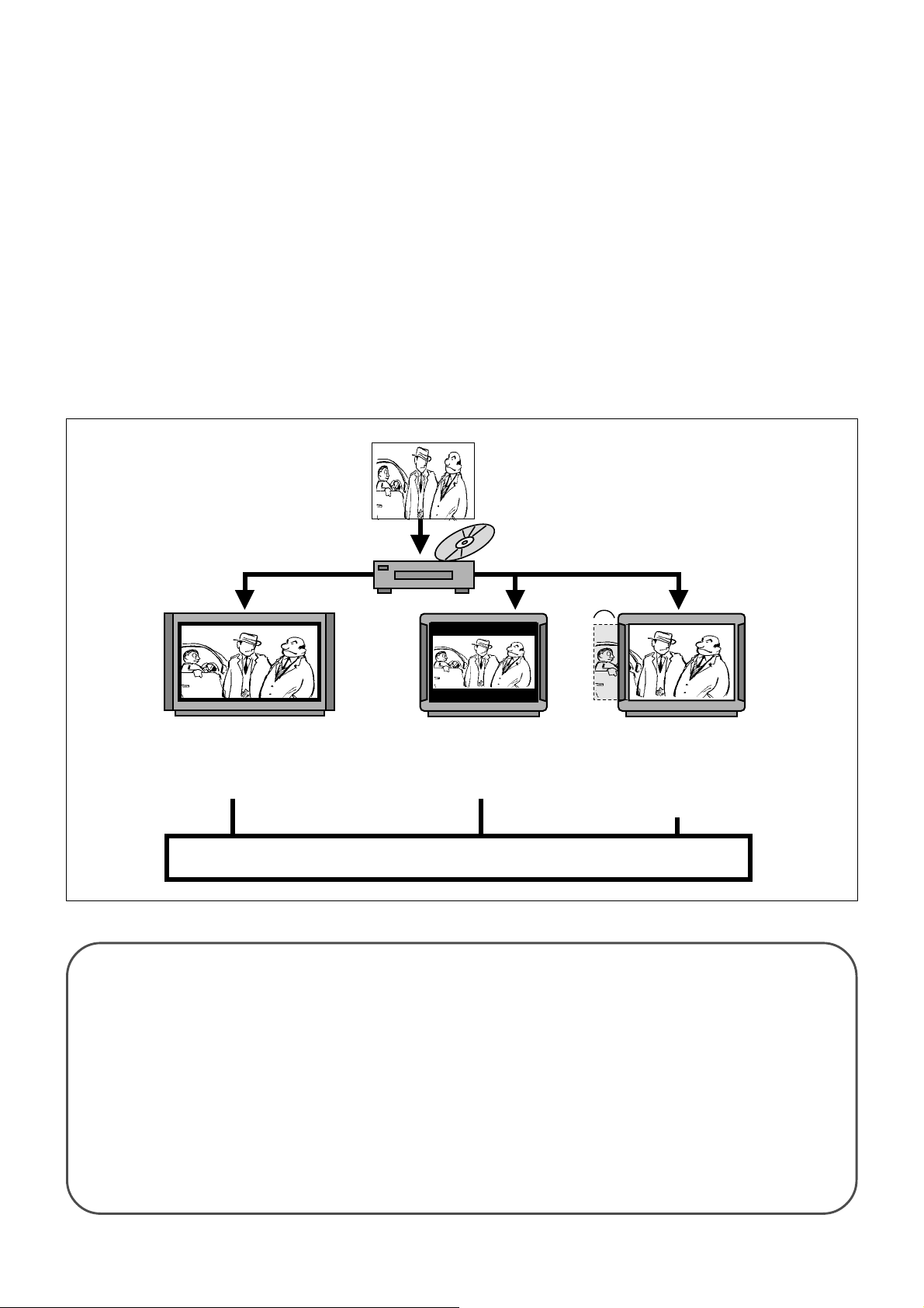
■Multi-aspect ratio capability
Software that allows the effective display of wide
pictures with a 16:9 aspect ratio on the TV screen of a
different aspect ratio can be created in the DVD-Video
format. Pictures with a 16:9 aspect ratio are
compressed horizontally for recording on a disc capable
of the multiple aspect ratios. When playing them back
on a TV or monitor with a 16:9 aspect ratio, the pictures
are decompressed horizontally by the “full” mode, one of
several TV screen modes, without deterioration of the
horizontal resolution. The pictures are reproduced in the
16:9 aspect ratio, completely filling the wide screen.
For viewing 16:9 pictures on a 4:3 screen, a disc can be
produced with the “pan and scan” mode in addition to
■Multi-aspect ratio capability
the basic “letter box” mode. In the letter box mode,
pictures are reproduced with black bands above and
below the picture. In this case, scanning lines of the
picture portion are reduced from 580 to 430. In the “pan
and scan” mode, 16:9 pictures are reproduced by
trimming the left and right portions of the playback
picture itself for viewing on a 4:3 screen. Information
regarding what parts are to be trimmed at what time are
stored on the disc, and upon playback the player
outputs the picture trimmed in the desired fashion.
Functions included in MPEG2 are used in the “pan and
scan” mode. Data specifying display regions of coded
pictures in units of fields can be output by MPEG2.
Wide pictures with 16:9 aspect
ratio are compressed horizontally
and the "squeezed" pictures are
stored on the DVD-Video disc.
On Wide Screen
Decompressed by “full” mode
(TV screen mode). Aspect ratio
will be suitable to for a wide screen.
On 4:3 Screen
Selecting the “letter box” mode,
wide pictures are reproduced
with black bands.
User-selectable playback mode
Questions & Answers
How does seamless playback work?
trimmed part
On 4:3 screen
Selecting the “pan and scan”
mode, appropriately trimmed
pictures like a movie retrimmed
for TV broadcast are reproduced.
34
A 4 Mbit memory called a track buffer is mounted in
a DVD player for variable rate playback. The
seamless playback function makes good use of this
track buffer memory. The time required for the
pickup to read the necessary data by jumping
tracks on a disc recorded with multi-angle function
to play back selected pictures and audio is
absorbed by this memory, and pictures are played
back continuously without a break. The operation of
seamless playback is basically the same as that
of ESP (electronic shock protection) buffer memory
in portable CD and MD players.
Page 36
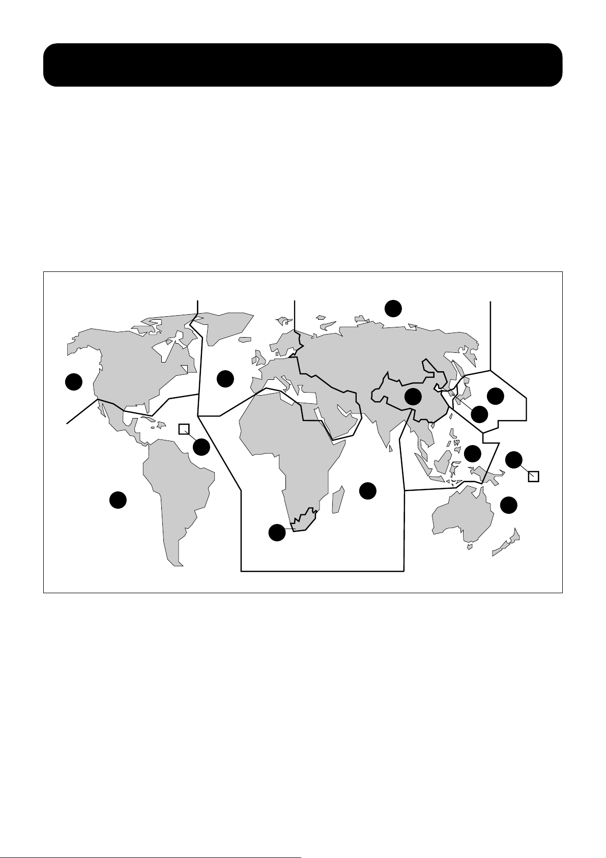
Copyright protection system in DVD-Video
■“Regional Code” controls playback in six regions of the world
A new movie released in the U.S. is normally released
overseas several months later, and the schedule for
movie releases can differ greatly by region. If the DVDVideo software of a movie is released in the U.S. before
the movie itself is released in a certain region, and if the
U.S. version software is imported into that region, it will
possibly affect the movie business in that region.
The playback management system
introduced with DVD Video divides the world into six
■The six ID regions of the world
1
2
sales regions and sets a region ID for each region on
both players and discs. This functions to allow playback
of discs only in their applicable region. The ID applicable
to a sales region is registered on players , and unless the
ID on a disc and the ID on a player match, the software
cannot be played back if the ID is recorded on the disc
by intention of the copyright holder. Reproduction in
more than one region may be made possible by how the
ID is set, so once-famous movies may be available for
playback in all regions.
5
6
2
3
1
5
4
2
■“Copy Protection System” links software and hardware
A system designed to protect copyrighted works from
illegal copying by the intention of copyright holders in
either the analog interface or a future digital interface is
incorporated into DVD-Video. Particularly in the case of
digital copying, digital data reproduction will be
controlled by linking software and hardware (including
the computer field) with highly advanced scrambling
technology. Although a DVD player is not equipped with
digital picture output capability, if the analog copy
protection is added to picture signals to protect the
copyright, the analog picture output cannot be recorded
with the proper quality. A disc free of the copyright
protection, however, can be copied.
3
1
4
35
Page 37

DVD-Video software production
The DVD-Video software production process can be
summarized as the planning and production of video
and audio sources, authoring, and then disc production.
Telecine conversion is required before authoring in
producing movie software and this process plays an
important role, along with authoring, in deciding the final
picture quality of DVD-Video software.
■Telecine
In producing movie software, pictures and audio
recorded on film must be converted into video and audio
signals before storing them on video tape. This process
is called “telecine” and the converted signals are stored
by a D1-format digital VTR as the studio master in
producing DVD-Video software.
There are a several types of telecine conversion systems.
To convert picture information on film into video signals,
the difference in characteristics of films and video tapes
as media should be taken into consideration, and some
Video and audio sources must be of high quality to
make full use of the high image and sound quality of
DVD-Video. Using films such as inter positives, which
are very close to the original films in quality, are being
considered in Hollywood for use in converting movies by
telecine processing.
calibration in the reproduction of hue and gradation is
necessary. Sometimes, color is calibrated closely for
each cut (scene by scene) by actually viewing the
scenes, and this requires deep knowledge and expertise
in movie making as well as video production.
When converting movie images into video signals by the
telecine process, conversion without degrading both
image and sound quality is made possible since all
processes, from calibrations and signal processing to
recording by digital VTR, are performed digitally.
■Authoring-the process
“Authoring” is the entire process from encoding pictures,
audio, and subtitles by applicable data compression
systems to combining them into recordable digital data.
The MPEG2 real-time video encoder using
sophisticated, special-purpose high-speed digital
processors is employed in picture data compression.
When encoding pictures by the MPEG2 video encoder,
data volume is distributed by the variable bit rate (9.8
Mbps max.) according to the condition of the images. It
is important to maintain high and even picture quality
■Authoring - MPEG2 video encoding
The “two pass coding” method which reads digital image
data recorded in the digital VTR twice is used in the DVD
MPEG2 real-time video encoder which employs a
variable bit rate. At the first pass, the whole volume of
images to be recorded is analyzed as to how much data
volume is required as to when and what parts of
pictures, and this information is recorded statistically.
Software for picture data volume analysis and distribution
contains the algorithm representing the expertise of
software companies, and differences in expertise are
throughout the entire content using available capacity.
Surround audio is encoded by the Dolby Digital (AC-3)
encoder, while subtitles and the operation menu are
encoded as subpicture data. After encoding, all video,
audio, and subpicture bit streams are added with control
commands for interactive functions, such as the multistory function, and multiplexed according to the DVD
logic format into one data entity. Error correction codes
are added and 8-16 modulation is performed on the
data before recording on the glass master disc as the
original data.
reflected as differences in picture quality even though the
same source is used to produce the software. Actual
data compression is performed at the second pass
according to data produced at the first pass. The
subjective micro adjustment in data volume distribution is
also done visually after computer-based encoding is
completed. Prefiltering to process appropriate noise
reduction to R, G, and B before encoding is also an
important process requiring the extensive knowledge and
expertise in high quality image production.
36
Page 38
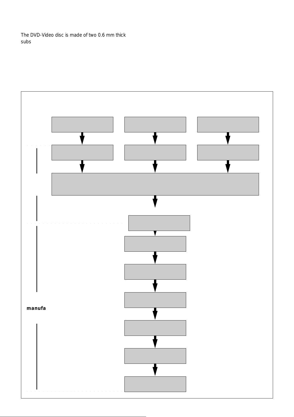
■Disc manufacturing
The DVD-Video disc is made of two 0.6 mm thick
substrates bonded back-to back, though the material
and manufacturing process of the DVD-Video disc
almost the same as with CD. The process of bonding
the two substrates is the last required process in disc
manufacturing, and this represents the addition of one
process to manufacturing when compared to the singleconstruction CD.
■Authoring and disc manufacturing process
video/audio master
○○○○○○
MPEG2 video encoding
bit stream bit stream bit stream
surround audio master
AC-3/MPEG audio
When considering productivity, DVD-Video is suitable for
large scale production of software in comparison with
video tape media which theoretically requires a one-toone copying process although a high speed magnetic
copying system is available. This is another excellent
feature of optical disc media.
subtitle data
encoding
subtitle encoding
authoring
multiplexing of video, audio and subtitles
process
○○○○○○○○○○○○○○○○○○○○○○○○○
disc
manufacturing
process
cutting master
glass master (the original
disc) produced by laser
metal master/stamper
produced
molding (injection molding
by stamper)
reflective layer spattering
process
○○○○○○○○○○○○○○○○○○○○○○○○○
protective layer spin-
coating process
bonding the 0.6 mm thick
substrates
37
Page 39
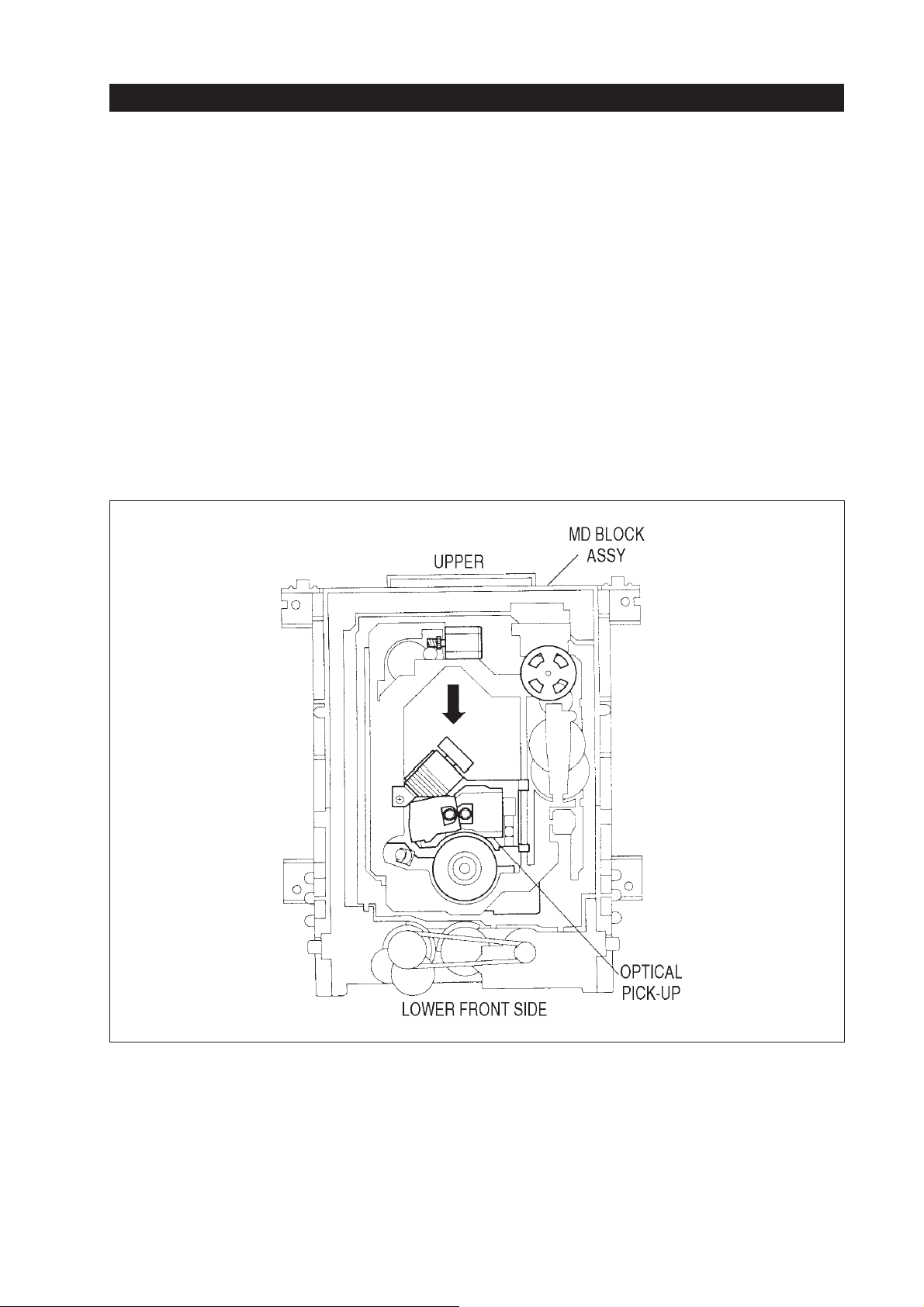
OPU, RF amplifier and servo processing
OPU, RF amplifier and servo processing
1. Optical pick-up unit (OPU)
1.1. Overview
Sony’s DVD Players DVP-S315 and DVP-715
whichare available on the European market, are constructed for playing CD & DVD discs. Therefore the
OPU of these DVD Players containtwo different optical systems in one housing. One is used for reading
out the DVD, the other one is used for reading the
CD.
Figure 1-1 shows the view on the mecha deck; you
can observe the two lenses of the different optical
systems.
Fig. 1-1
5
Page 40

1.2. Differences between CD & DVD optical
pick-ups
OPU, RF amplifier and servo processing
TheDVD part of the OPU uses adifferent laser diode
which produces another wavelength; according to
this also the NA is different (higher).
Please note that the laser diode used in the DVD side
is approx. 4 times more sensitive to electrical shocks
Also for detecting the focus and tracking error voltages different principles are used for the DVD and
CD side. Explanations for this you will find on the
next pages.
Figure 1-2 shows the main differences.
than the one used for CD. As it is well known from
otherlaser pick-ups there are also short lands for protecting the laser diodes. As we have two laser diodes
inside the pick-up we have also two short lands, one
for each diode.
The 2-axis device used in the DVD part is much
smaller than the one of the CD side, it is a so-called
“µ-2-axis device”.
Numeric aperture (NA)
As mentioned in the table before the value of the NA
for DVD use is higher than the one for CD use. A
higher NA means the focussing depth is narrower,
even the tilt tolerance and the disc thickness become
lower.
Figure1-3 shows the relation of theNA value and the
angle θ which influences the focussing.
Specifications DVD CD
Optical system Non-polarized
infinite type
Actuator µ-2-axis device 2-axis device
Objective lens Glass Plastic
Non-polarized
laser coupler type
NA (numeric aperture) 0.6 0.45
Focus error Astigmatic method Differential 3-divided focusing
Tracking error DPD (differential phase detection)
method
Wavelength (λ)
650 nm 780 nm
TPP (top hold push pull) method
Fig. 1-2
(1) HIGH NA
NA = sin
θ
NA : NUMERICAL APERTURE
NA
CD
MDP
DVD
~ 0.45
~ 0.51
~ 0.6
θ
Fig. 1-3
6
Page 41

OPU, RF amplifier and servo processing
As you already may know from other OPUs (e.g.
fromCD orMD): avoiddirect viewto thelaser light!
The used laser light power for reading out a DVD is
between 180 µW for a single-layer disc and 300 µW
for a dual-layer disc (CD is approx. 120 µW).
Lens cleaning
Asthe minaturized µ-2-axis device can easily be bent
be careful while cleaning the lens of the DVD part.
Firsttry to remove the dust with a hand blower; if itis
necessary use a cleaning cotton swab (P/N
7−740−900−65) and wipe very carefully in a spiral
way from the inner to the outer circumference. The
Sony cleaning liquid can be used.
KHS-180A
10285H
968490
Aftercleaning it is important tocheck the jitter value,
ifthe jitteristoo highandcannot beadjustedby using
the tangential screw the µ-2-axis device may be broken! (see Jitter Adjustment).
OPU label
There is an identification label mounted at the OPU.
In the following figure you will find the explanation
of the used characters.
PART NAME
MANUFACTURING DATE:
=
"10"
DAY
=
MONTH, WHICH CAN BE
"2"
JAN.- SEPT. (1 - 9) OR
X = OCT.,Y = NOV., Z = DEC.
=
YEAR
"8"
=
ACTION NR.
"5"
=
FACTORY LINE NAME
"H"
IOP VALUE INDICATION (OPERATIONAL CURRENT OF EACH OPTICAL SYSTEM IN mA):
THE FIRST THREE DIGITS INDICATETHE DVD IOP : 968 = 96.8 mA.
NOTE
: IF THE IOP VALUE IS HIGHER THAN 100 mA THE PRINT SHOWSTHE LAST DIGITS,
OMITTING THE HIGHEST ONE.
THE LAST THREE DIGITS INDICATETHE CD IOP : 490 = 49.0 mA
Fig. 1-4
7
Page 42
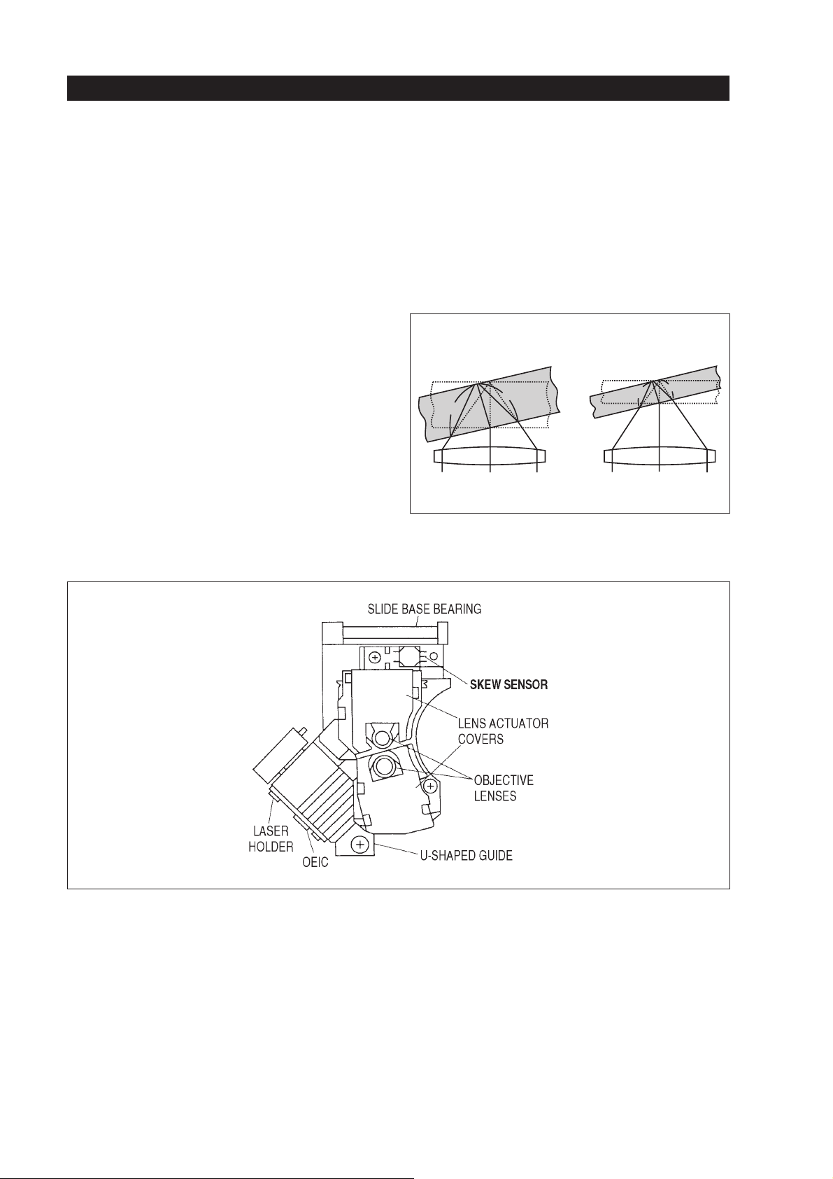
Effect of tilt angle
OPU, RF amplifier and servo processing
ADVD is built by two parts, each one hasa thickness
of 0.6 mm. They are glued together. This construction prevents disc bend caused by temperature and
humiditychanges.Buton the other hand a disc wrapping may occur at the outer circumference of the disc
caused by the higher thickness of 2 x 0.6mm. The
wrapping can be described by the value of the tilt angle which differs in relation to the disc’s thickness.
During readout a changing tilt angle will cause a
skew error, which will disturb the read-out disc signal.To detect this tilt effecta so-called SKEW sensor
is mounted on the surface of the OPU. By using the
skew error voltage the OPU lens is moved in parallel
to the disc surface.
Figure 1-5 shows the relation between disc thickness
and tilt angle.
DISCTHICKNESS INFLUENCES EFFECTS OFTILT ANGLE
A THICKER DISC CAUSESTHE LENGTH DIFFERENCE
BETWEEN A AND A' TO BE LARGER
A
A
A'
DISC THICKNESS
t = 1.2 mm
A'
DISC THICKNESS
t = 0.6 mm
Fig. 1-5
Figure 1-6 shows the position of the skew sensor.
Fig. 1-6
8
Page 43

OPU, RF amplifier and servo processing
Physical parameters for readout
Parameter CD-ROM mode 1
(74 min.)
Spot diameter
W=λ/(2xNA)
0.87 mm 0.54 mm
DVD-ROM
(single layer)
Track pitch p 1.6 µm 0.74 µm
Minimum pith length (3T) =3xc 0.84 µm 0.40 µm
Linear velocity v 1.21 m/sec 3.49 m/sec
Optical cut-off frequency
=v/W=vx2xNA/λ
f
CO
1.4 MHz 6.44 MHz
Channel bit rate f=v/c 4.3218 MHz 26.16 MHz
Highest EFM frequency f
Size of program area on disc
=f/6 0.72 MHz 4.36 MHz
I3
a=πx(R
max
2
–R
min
2
)
8600 mm
2
8760 mm
Fig. 1-7
Remarks
Thesmaller spot size increasesthe optical resolution,
without sacrifying system margins.
1.3. The optical systems inside the OPU
Before it was mentioned that inside a DVD-OPU
therearetwodifferent optical systems, one for DVD,
FULL REFLECTION
MIRROR COURT
HALF MIRROR COURT
REFLECTION FACTOR =
20–25%
FULL-SCALE ABSORPTION
MEMBRANE COURT
one for CD.
1.3.1. The CD optical system
HALF MIRROR
COURT
1.52 mm
2
0.6 mm
AR
COURT
Itworks as a LASERCOUPLER system. This means
the laser diode itself, the monitor diode for controlling the light output and the detector unit for readout
are included in one block. Even the half mirror function, which is used for splitting between incoming
andoutgoing beam,is doneby thelaser couplerblock
Figure 1-8 shows the laser coupler from its outside.
Fig. 1-8
Figure 1-9 shows the optical components which are
included.
Figure 1-10 gives you an idea of the size.
9
Page 44
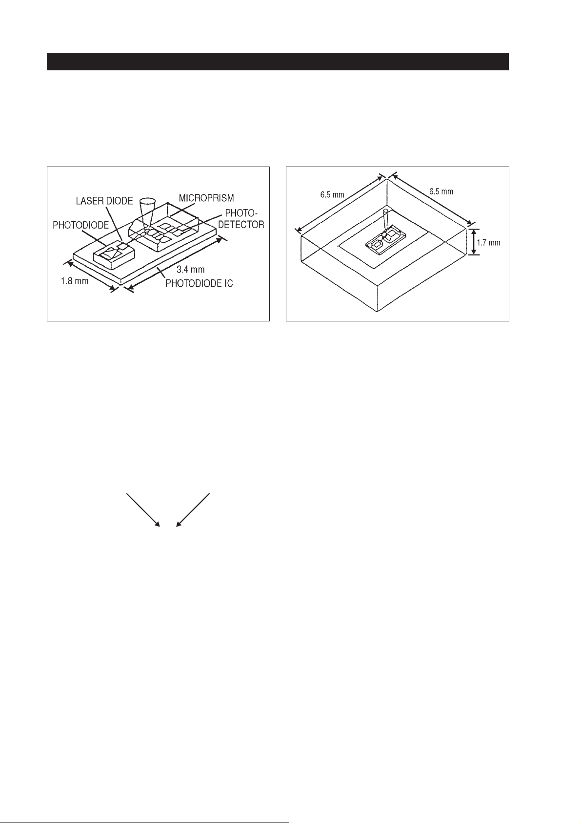
OPU, RF amplifier and servo processing
Fig. 1-9 Fig. 1-10
Tracking error detection
Trackingerror detection forCD is done withthe TOP
PUSH PULL principle. This method is a modified
PUSH PULL principle and cancels the DC offset,
which is the weak point of the normal PUSH PULL
system. For the TPP principle, two detectors each
withfour detector fieldsare used. Theerror voltage is
calculated by the following formula:
TE=(A2+B1+A4+B3)–(A1+B2+A3+B4)
TE=E–F
Figure 1-11 shows the arrangement of the detectors
PD1 and PD2. They are located on top of each other.
PD1 is next to the objective lens.
Figure 1-12 shows the light spotson PD1 and PD2 in
relationto thebeam positiononthe disc.The distance
from PD1 to PD2 is calculated in that way that the
spot position at the surface of PD1 is opposite to the
one of PD2, when the beam on the disc is in “off
track” position. “On track” results in the same light
amount on each detector.
10
Page 45
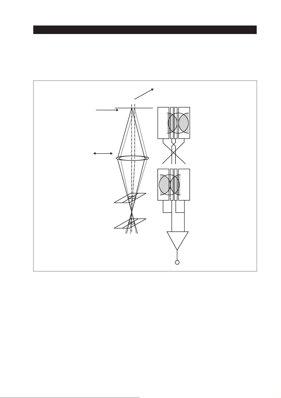
OPU, RF amplifier and servo processing
L
RADIAL
(TRACKING)
LENS
SHIFT
OBJECTIVE
LENS
PD1
PD2
TANGENTIA
DISC
A1 A3 A4 A2
PD1
B1 B3 B4 B2
PD2
EF
+–
Fig. 1-11
PUSH PULL
(E–F)
11
Page 46
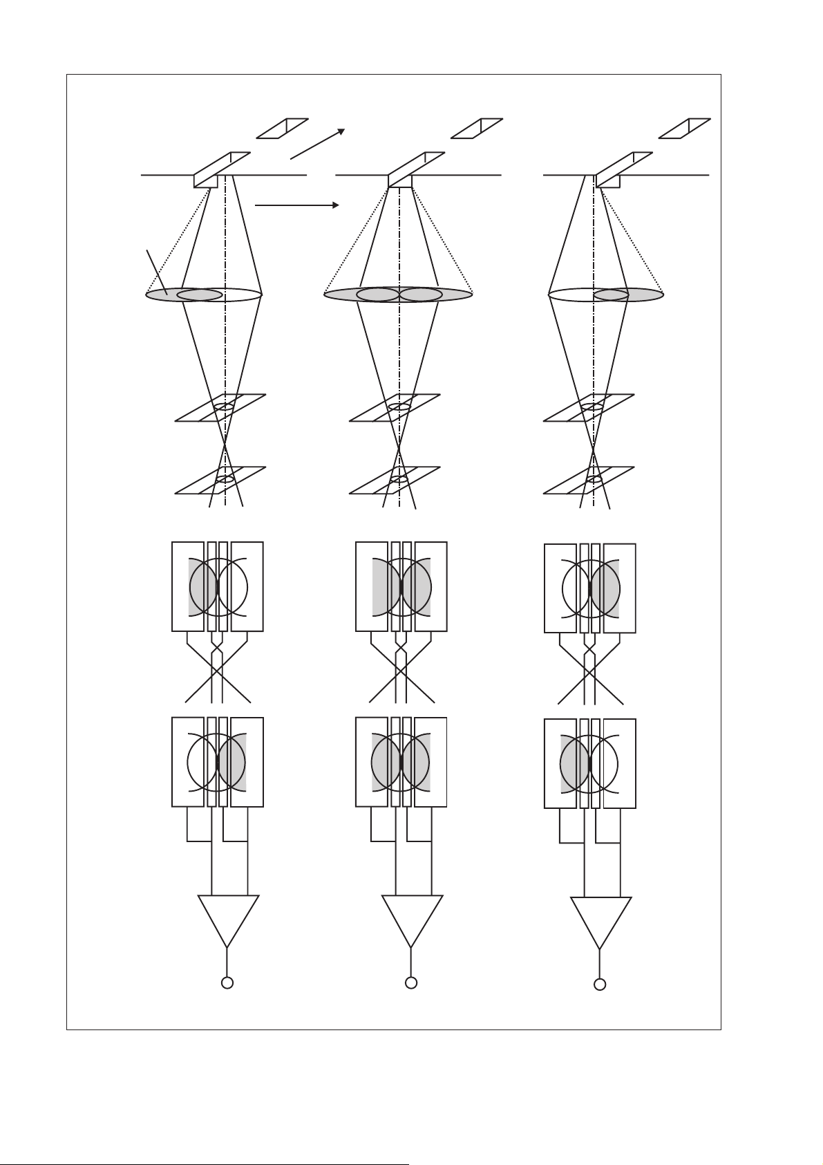
DISC
PRIMARY
DIFFRACTED
LIGHT
OBJECTIVE
LENS
DETRACK + ONTRACK DETRACK –
TANGENTIAL
RADIAL (TRACKING)
PD1
PD2
A1 A1
B1 B1
E=A2+B1+A4+B3
F=A1+B2+A3+B4
A3 A3
A4 A4
A2 A2
B3 B3
B4 B4
B2 B2
EE
+– +–
FF
A1
A3
A4
A2
B1
B3
B4
B2
E
+–
F
12
PUSH PULL
(E–F)
POSITIVET.E. NEGATIVE T.E.0
Fig. 1-12
Page 47
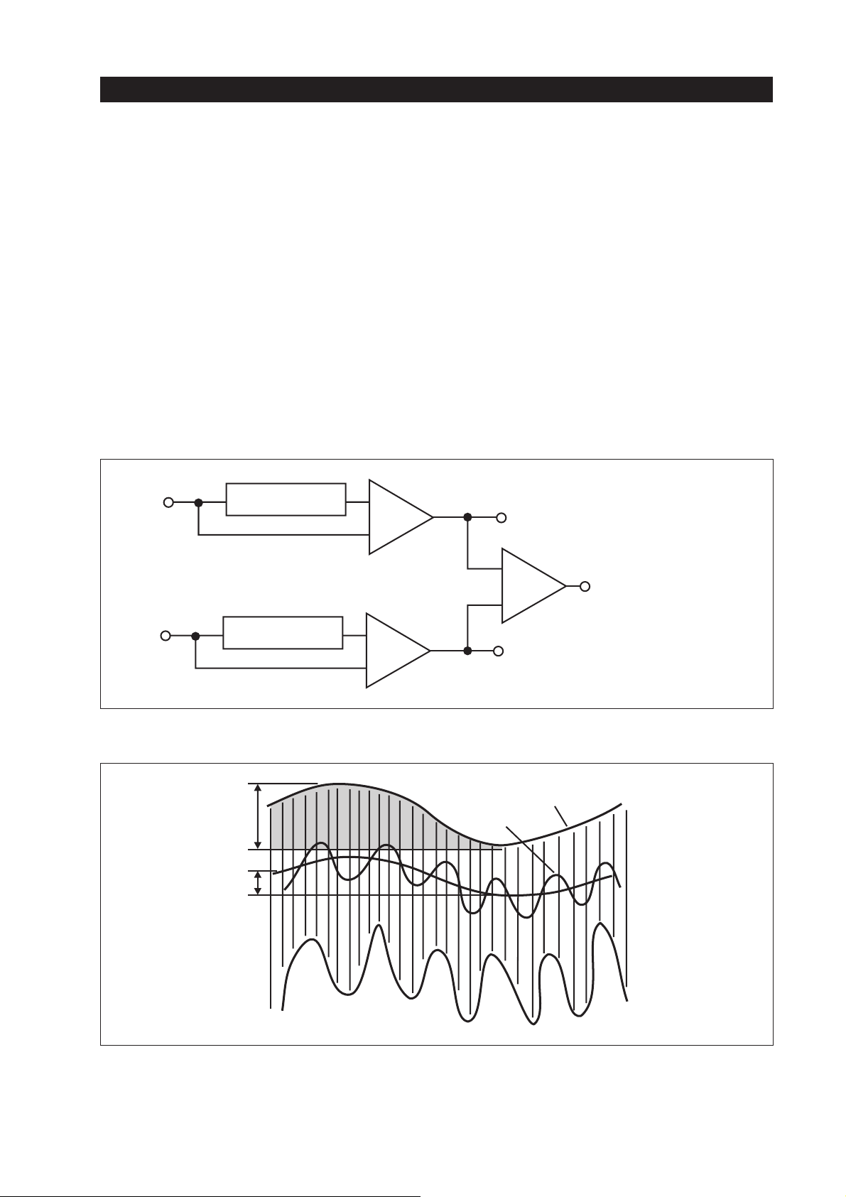
OPU, RF amplifier and servo processing
Astold shortly before, the advantageof the TPP principle is the cancelling of the DC offset. This is done
withTOP HOLD circuits switched in theE and F signal path. This means: The tracking error signal is detected via low-pass-filtering of the RF envelope
signal. Next the offset varation of the RF envelope
has to be separated and held. In order to cancel the
DC offset, occurred by lens shift, now the offset
variation will be substracted from the RF envelope
signal.The figures 1-13 and 1-14 show the block diagram and the signals respectively.
E
F
K x TOP HOLD
K x TOP HOLD
+
–
+
–
To cancel the DC offset the formula A Signal–bis
used. In the block diagram shown in figure 1-13 the
factor “K” which is a fixed value (< 1) calculated by
the designer is multiplied to the “TOP HOLD” value
which is calculated by the “a” peak signal shown in
figure 1-14. The figure shows the RF envelope of the
“E” signal. “a” shows the change of the RF envelope
peak level. The “A Signal” is the low-pass-filtered
RF envelope. “b” shows the offset change of the “A
Signal”.
TPP(E)=E–(KxE )
+
–
TPP(F)=E–(KxF )
TOP HOLD
TPP = TPP (E) – TPP (F)
TOP HOLD
Fig. 1-13
PEAK LEVEL
a
b
A SIGNAL
Fig. 1-14
Therefore envelope of “E” signal
13
Page 48
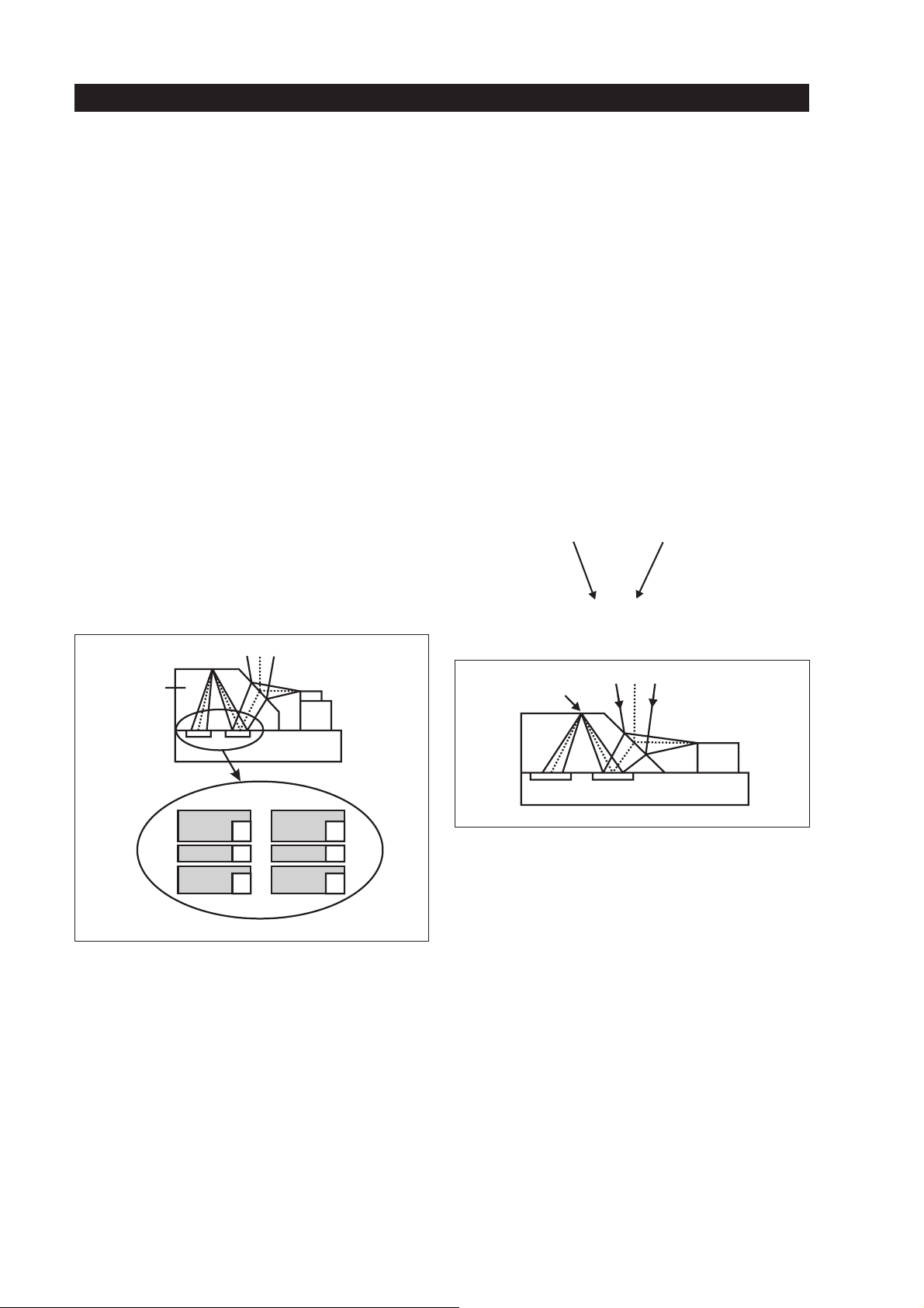
OPU, RF amplifier and servo processing
Focus error detection
Focurerror detection for CDis done with theD-3DF
principle, which means “Differential 3-Devided Focussing”. Two photodetectors (PD1 & PD2), each
with three detector fields, are used for this kind of focussing.Figure 1-15 shows the alignment of the photodetectors. These detector fields are named “A” up
to“C” (with and without mark).When the laser beam
onthe disc surface is well focussed the output of PD1
and PD2 is as follows:
A+C=BorA’+C’=B’
With respect to this the following formulas are used
for detecting the error voltage of PD1 and PD2:
PD1=B–(A+C)
PD2=B’–(A’+C’)
PRISM
LD
LOP
For detecting the focus error the built-in microprism
ofthelasercoupler block is very important. The light
beam reflected from the disc’s surface is coming
back to the surface of the microprism. If the beam is
well focussed at the information layer of the disc it is
also well focussed on the surface of the microprism.
Only when the focal point is on the surface of the
prism, will the light touch both photodetectors (PD1
& PD2) evenly, so that the size of both light spots becomes equal. See figure 1-16.
The formula for FE is follows:
[B–(A+C)]–[B'–(A'+C')]=FE
PD1–PD2=FE
FOCAL POINT
PD
A'
B' B
C' C
Fig. 1-15
LD
A
Fig. 1-16
14
Page 49
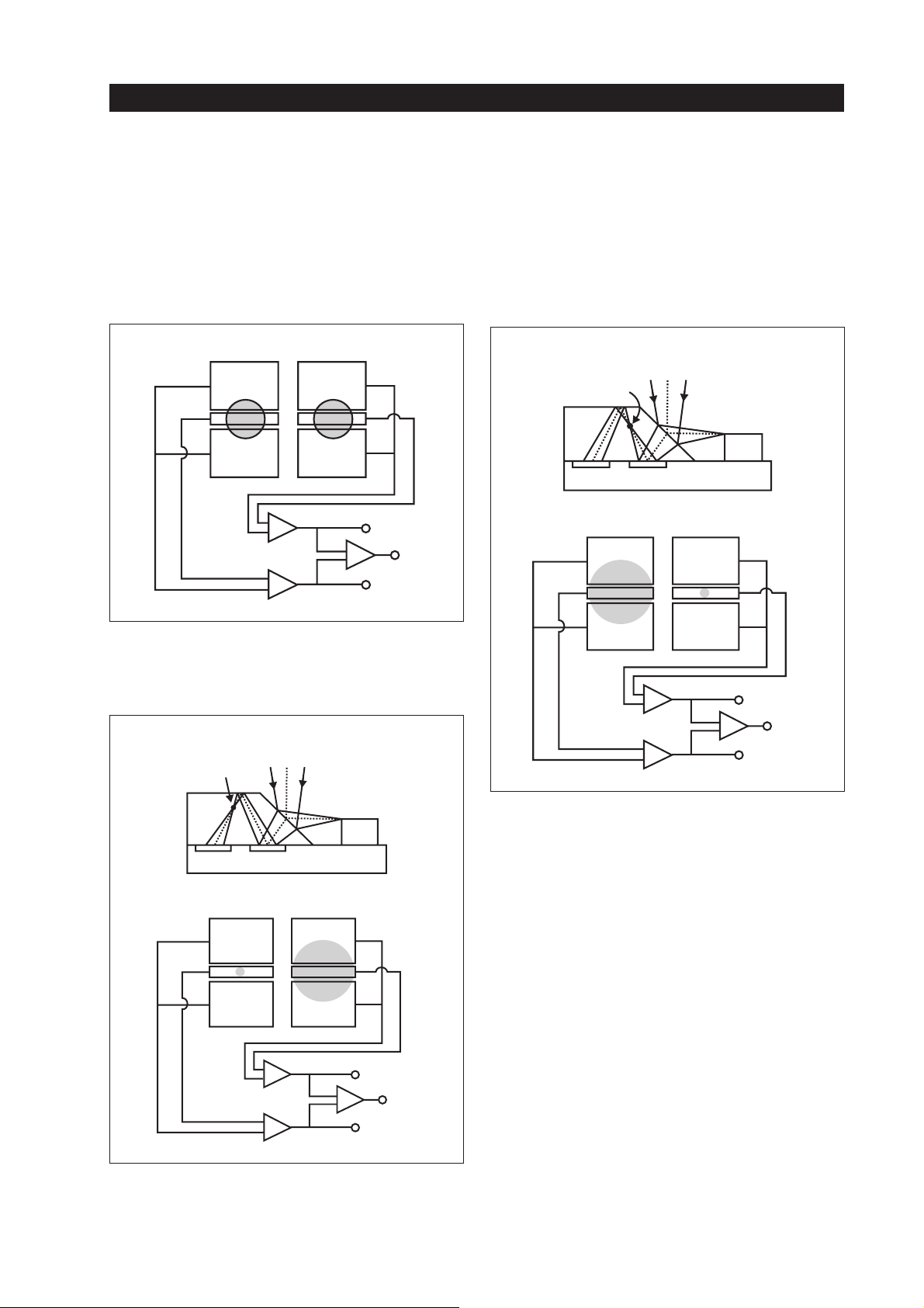
OPU, RF amplifier and servo processing
Figure 1-17 shows the spots on PD1 and PD2 when
the focussing is well done.
PD2 PD1
A' A
B' B
C' C
+
–
+
–
PD1
+
–
FE
PD2
Fig. 1-17
Figure1-18 showsthe spots onthe PD’s surfaceif the
focus adjustment is too close.
TOO CLOSE
FOCAL POINT
Figure1-19 showsthe spots onthe PD’s surfaceif the
focus adjustment is too far.
TOO FAR
FOCAL POINT
LD
PD1PD2
PD2 PD1
A' A
B' B
C' C
+
–
+
–
+
–
PD1 –
FE +
PD2 +
LD
PD1PD2
PD2 PD1
A' A
B' B
C' C
+
–
+
–
+
–
Fig. 1-18
PD1 –
PD2 +
FE –
Fig. 1-19
Conclusion on the OPU’s CD part
The CD part of the OPU is mainly built up by the LC
(Laser Coupler). It includes the LD (Laser Diode),
the PDs (Photodetector) for tracking and focussing
andthe monitordiode, whichcontrols thelight ouput.
The microprism of the LC works as a beamsplitter.
Further a separate mirror is used for guiding the light
in the direction of the disc. It sends also the reflected
light back to the LC. For moving the lens the wellknown 2-axis device is used. The CDoptical part is a
one-beam laser system. It uses the CD typical wave-
length (λ) of 780 nm.
15
Page 50

1.3.2. The DVD optical system
OPU, RF amplifier and servo processing
The DVD optical system works as a one-beaminfinite-type optical system. This means there is no
integration of the important optical parts, as we have
it in the LC. In this system there is a separate LD; it
sendsout the laser light (λ =650 nm) to a beam splitterwhichworksas a half mirror. Next the light, on its
way to the disc, is passing a collimation lens; after
thata mirror reflects itin the disc's direction. Thecollimation lens corrects the light to a parallel form. It
also sets up a defined beam diameter. Then the light
passes the lens, a µ-2-axis device can move this lens
in the horizontal and in the vertical direction for correcting tracking and focussing.
Thereflected light of the disc is passing again the objective lens, the mirror and the collimation lens. The
beam splitter sends the light to the photodetector. In
the DVD part of the OPU a photodetector built by
fourdetectorfieldsis used. The detector fields of this
photodetctor are named from “A” up to “D”. They
are used for detecting the focus and tracking error
signaland the RF readout,too. Another signal, which
is named “PI”, is extracted also from “A, B, C, D”.
The “PI” signal is used for detecting whether a single- or a dual-layer DVD is used. See also figure
1–23.
Tracking error detection
Tracking error detection for DVD is done with the
DifferentialPhase Detectionmethod (DPD). OnePD
with four detector fields is used. The principle is as
follows:
The pit edges are detected by the four detector fields
during normal playback. The signals “A, B, C, D” of
the detectors are equalized and sent to separate comparators. An internal reference voltage determines
the threshold level of the comparators. The output of
each one is squarewave-modified. The output timing
is in relation to the signal level, coming from the detectors. Next the comparators’ output signals “A”
and “B” are sent to one phase detector; the phase difference signal of “A” and “B” is output. The same is
done with the comparators’ ouput signals “C” and
“D”.As a result a secondphase difference output signal from “C” and “D” is available. To get the actual
TE signal the phase difference signals “A/B” and
“C/D” are added and low-pass-filtered. See figure
1–21.
TE = ∆ phase A/B + ∆ phase C/D
Figure 1-20 shows the PD and the spot in ideal position and shape.
B
CD
Figure 1-21 shows the block diagram of the tracking
error circuit.
A
TRACKING
DIRECTION
Fig. 1-20
16
Page 51
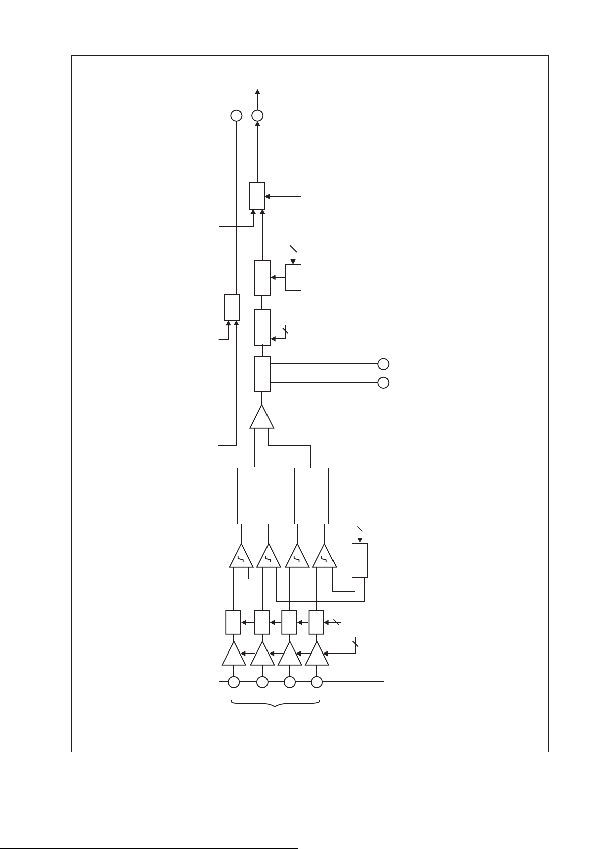
PP
40
TO
TE
MB
38
MUX
BOARD
FROM
4
DVD-ROM
S-PORT
DAC
COMP.
MUX
PP
LPF GCA OFFSET
+
PHASE
DETECTOR
VC
4
FROM
S-PORT
PHASE
DETECTOR
VC
FROM
8
DACx2
S-PORT
CN
CP
56
EQ
GCA
1
A2
EQ
GCA
2
B2
FROM
EQ
GCA
3
C2
DVD
PICKUP
OPTICAL
Fig. 1-21
EQ
GCA
4
D2
2
FROM
S-PORT
3
17
Page 52

Focus error detection
OPU, RF amplifier and servo processing
Focuserror detection for DVD is done with the astigmatic method, which we know in general from CD
and MD Players. From infinite OPU types used in
former times for CD we know that an additional astigmatic (cylindric) lens is used for detecting the focus error. This is the difference to the optical part
which is used for DVD. There is no separate astigmaticlens, instead of this the beam splitter is usedfor
creating the astigmatic effect.
Thisoptical system is calculated in the way that if the
spot is well focussed on the information layer of the
disc, the reflected light spot is also well focussed on
the surface of the beam splitter. If it is well focussed
on the surface of the beam splitter the spot at the PD
willbe ina roundshape inthe centreof thefourdetector fields. If the focus adjustment isnot well done the
shape of the light spot on the PD changes from round
to elliptic caused by the astigmatism. Depending on
the shape on the detector’s surface it is possible to
calculate the focus error by the following formula:
(A+C)–(B+D)
For using dual-layer discs the system is able to do a
focus jump from layer 0 to layer 1 controlled by the
syscon via the focus servo circuit. There is no differencein detectingthe focuserror itselfon layer0 or1.
Figure 1-22 shows the different shapes of the spot on
the surface of the PD in relation of the focus state.
BBBAAA
DDDC CC
DISC TOO CLOSE FOCUS WELL-DONE DISC TOO FAR
Fig. 1-22
Figure 1-23 shows the structures of the CD and DVD
optical part of the OPU.
18
Page 53
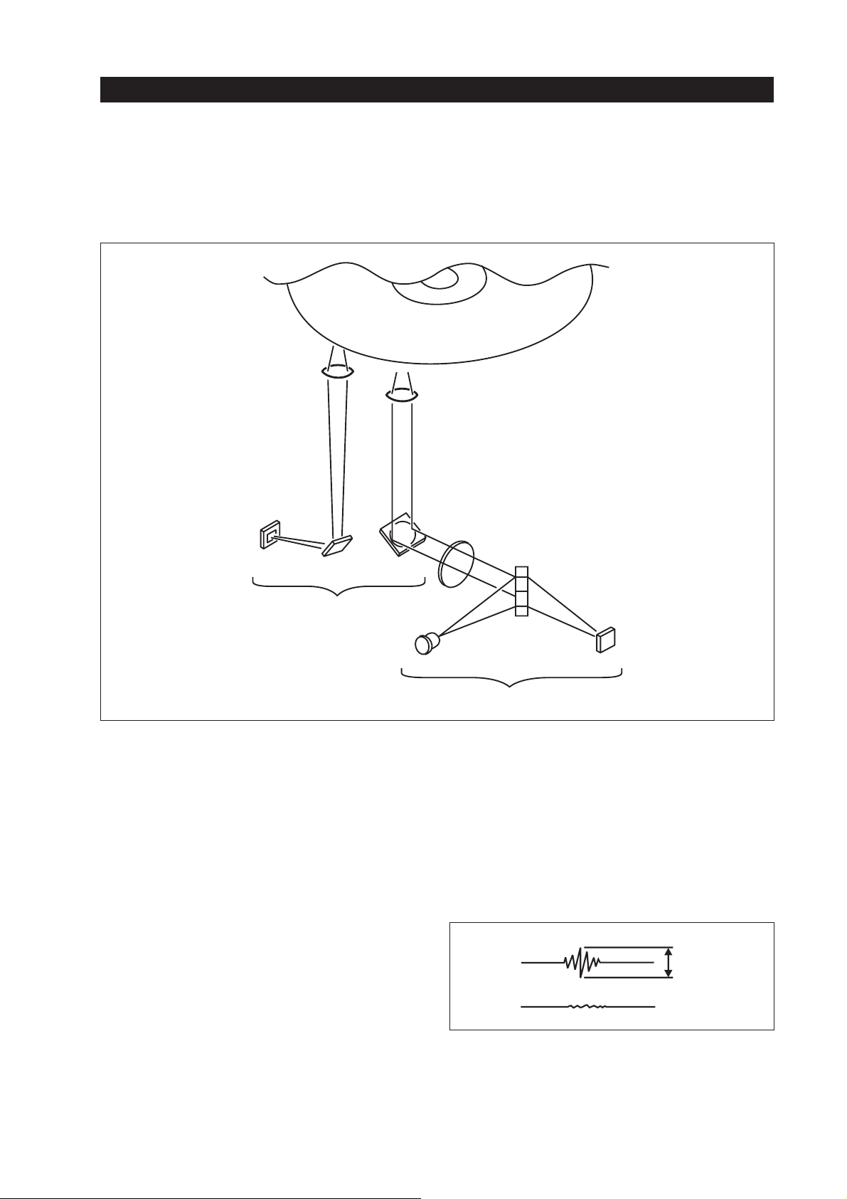
OPU, RF amplifier and servo processing
OBJECTIVE
LENS
LASER
COUPLER
MIRROR
DISC
OBJECTIVE
LENS
COLLIMATOR
LENS
BEAM
SPLITTER
CD PART
LASER DIODE
Fig. 1-23
DVD optical systems built in one OPU
1.3.3. Disc detection
At the beginning of the playback function the set has
todecide whether a CD or a DVD is inserted. When a
DVD is used it can be a single-layer or a dual-layer
disc, so a separate detection for this has to be done.
CD or DVD judgement
When the PB starts, the sled motor will move the
whole OPU several times from the inner to the outer
circumference,also thefocus searchfunction startsat
theCD andat the DVDpart of theOPU. After focussing during this first movements the tracking error
voltage level of the CD optical system is controlled.
Ifa DVDisinserted theT.E.voltage comingfromthe
CD part is below 0.4 V
caused by the smaller pits
PP
and track pitch of the DVD. If a CD is inserted the
PHOTODETECTOR
DVDPART
T.E. voltage of the CD optical system is around
2V
.
PP
Therefore the disc judgement is done by controlling
the T.E. voltage of the CD optical system. See figure
1-24.
CD
APPROX.
2Vp-p
DVD
Fig. 1-24
Tracking error votlage
19
Page 54

OPU, RF amplifier and servo processing
Single- or dual-layer DVD (SL / DL)
The difference between a single- and a dual-layer
DVDis theintensity of thereflected light.For this the
sumlevel PI of the DVD optical system is checked.It
is built by the formula “A+B+C+D”.
The reflectivity of an SL disc should be between 45 80%; mostly we calculate with 70% (this is also the
value of the test disc). The reflectivity of a DL disc
shouldbe between18 - 30%;mostly we caculatewith
25%.
As mentioned before the judgement between SL and
DL discs is done by checking the PI voltage level,
which is approx. 1V for an SL and 0.5 V for a DL
disc.
See figure 1-25.
APPROX.
1V
SL
1.3.4. Skew sensor
The skew sensor is mounted on the surface of the
housingof theOPU. It isused for detectingthe tiltangleof a disc wrapping.See figure 1-5. Soit will avoid
a skew error at the landing spot on the surface of the
main PDs, which should disturb the RF readout.
The skew sensor itself is also built with two PDs
1and PDS2)and one infrared LED. If the disc is
(PD
S
parallelto theOPU thereflected lightamount oneach
skew photodetector is the same. If the light beam is
not perpendicular to the disc, the light amount on the
surface of the PDs will be different. In principle the
error voltage is calculated with the formula “PD
2”. This error voltage is sent to the tilt servo cir-
PD
S
S
1–
cuit which is controlling the movementof the OPU’s
base unit. For calculating an average level which
avoids too heavy reactions of the tilt servo the formula is modified as follows:
PD PD
12
−
SS
PD PD
12
+
SS
DL
Fig. 1-25
SL/DL judgement by checking PI level
APPROX.
0.5V
20
Page 55

OPU, RF amplifier and servo processing
2. Servo circuits
2.1. Overview
The servo circuits of a DVD Player are devided into
several functions. Most of them we know from CD
sets. Roughly we can devide the servo-related functions as follows:
RF front end for DVD & CD
•
Focus servo DVD/CD
•
Tracking servo DVD/CD
•
Sled servo DVD/CD
•
Spindle servo DVD/CD
•
Tilt servo
•
The processing of all servo circuits is totally separate
fromthe one which is used for audio and video signal
processing.
The following block diagram shows a rough overview of the whole set. You can reconize the servorelated parts as follows:
The OPU is connected to the DVD and CD front
ends.They are located on the TK-47 board (see Service Manual, page 3-1). IC 006 works as the DVD RF
amp, IC005 is the CD RF amp. These RF amplifiers
are generating the various error voltages which are
sent to the servo DSP, which is IC506 (SM/ 7-3).
Also the RF signal isgenerated by the front ends,but
these signals are not requested for the servo circuits
(only the spindle servo needs the RF sync), they are
processed at the RF processor IC806. The servoDSP
and the RF processor are located on the MB-78
board.
Separatedriver ICs for forcing the focus and tracking
coils, sled motor, spindle motor and tilt motor are
used.
Thesyscon ofthe set iscontrolling theservo DSP, the
RF processor and all other important circuits like the
AV decoder, video encoder and others. A data bus is
connecting the processing ICs with the syscon. See
figure 1-26.
21
Page 56
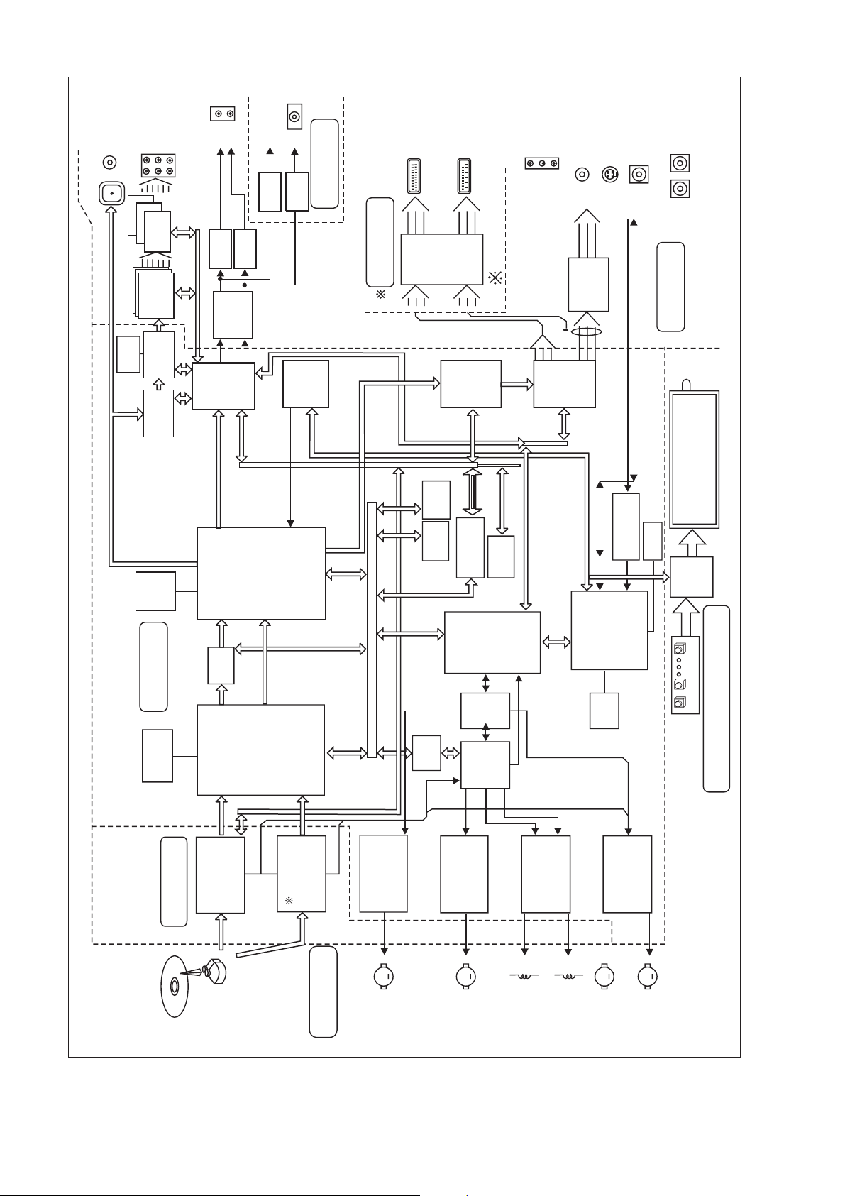
COAX
OPT
OUT
AU-L, R
AC-3
&
6CH OUT
2CH LPF
X3
2CH LPF
BUFF
256K
SRAM
AC-3
2CH LPF
2CH DAC
AC-3
6CH DSP
DIR
X3
(CXD8750N)
(MB86342)
LC89051V
DAC
LPF
MGA
BUFF
2CH DAC
SH Serial
HEAD
LPF
LPF
BUFF
(CXD8750N)
(CXD8746Q)
BUS-Gp3
PHONE
BUFF
LPF
BUFF
OSD
(MB90096)
Bus
IF Serial
HP BOARD
21p
EURO
EU BOARD
SH Serial
BUS-Gp2
21p
&
SW BLOCK
{
EURO
LPF
(2’nd)
Ω
75 DR
6dB AMP
DNR
EURO ONLY
{
(CXD1854)
SH Serial
BUS-Gp3
RGB OUT
R.G.B.
V OUT
LPF
VIDEO
ENCODER
(CXD1914)
SH SERIAL
6dB AMP
BUS-Gp2
Y/C OUT
Ω
75 DR
V, Y, C
S-LINK
S-LINK
or
CTRL-A1
AU BOARD
FLO
32M
SDRAM
MB BOARD
4M DRAM
SPDIF
MPEG
TK BOARD
OUT
STREAM
DECTRIPT
SH Serial
DVDFRONT END
AVDEC
(L64020)
CD-DATA BYPASS
CD RF
(RF PROCESSOR)
BUS-Gp3
(SSI33P3720)
R, G, B, I
OSD
CD RF
SH Serial
[3:0]
(CXD1865)
(CXA 1081Q)
SH Serial
CCIR 601
Parallel BUS
SPDL DR
BUS-Gp3
(LB 1896)
CPU EXT
CPU EXT
SGA
(CXD8747)
RAM
ROM
SH Serial
SLED DR
BUS-Gp3, 4
EXP I/O
(CXD8728)
L GATE ARRAY
(SH)
SYS µ-COM
ARRAY
LGATE
SERVO
(LA6527)
SH Serial
BUS-Gp3
EEPROM
(CXD8728)
DSP
(CXD8730R)
BUS-Gp2
SH SERIAL
SH SERIAL
FCS/TRK DR
BUS
IF SERIAL
BUS-Gp1
(BA5981)
CTRL-A1
16L
I/F µ-COM
(MB90678)
EXT
ROM
TILT/LD DR
SIRCS
(NJM2191)
(BA5912)
RESET
(µpc393)
FLO
DRIVER
KEYS
FRONT (FL, FR) BOARD
BUS-Gp3, 4
22
M
SPDL MOTOR
M
SLED MOTOR
MD BLOCK
Fig. 1-26
Block diagram DVP-S715
FOCUS COIL
TRACKING COIL
M
LOADING MOTOR
M
TILT MOTOR
Page 57
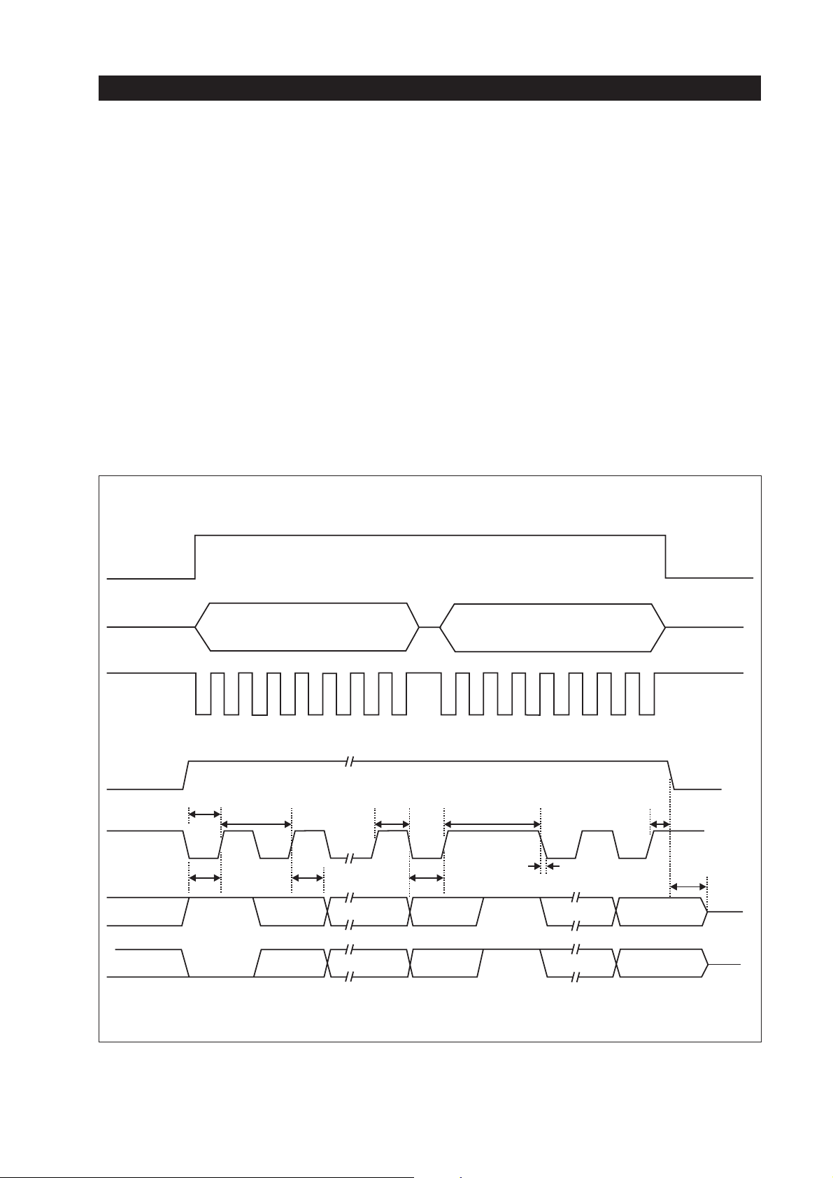
OPU, RF amplifier and servo processing
2.2. DVD & CD RF amplifier ICs (IC006 &
IC005)
The DVD RF block is built by IC006
(SS133P3720A) on the TK-47 board. The signals A,
B,C, D of the DVD optical system are sent to this IC.
Theinputs of the four PDs are usedfor generating the
DVD F.E. and T.E. signal. Input pin7-10isused for
generating F.E., pin1-4receives the A, B, C, D signalsvia capacitors for generatingthe T.E. voltage. At
pin30 a MIRR out signalandat pin 37 the PIsignalis
available.
SDEN
SDATA
SCLK
ADDRESS, 8-BIT
For creating the RF signal the A+B+C+D sum is input to IC006 pins 63 and 64
IC006 is controlled by the syscon via the serial interface. Various values are adjustable via this interface
which connects the RF amp with the syscon via the
large gate array IC804. An 8-bit address identification and an 8-bit job order are used. Figure 1-27
shows the arrangement of the interface databy a timing diagram.
DATA, 8-BIT
SDEN
SCLK
SDATA
(READ)
SDATA
(WRITE)
TSENS
TCLK TCKH TTRN
TDS TDH TCKL
R/W
R/W
ADDR 0
ADDR 0
Fig. 1-27
TSENH
TDSKEW
ADDR 6 DATA 7
ADDR 6 DATA 7
TSENDL
23
Page 58

OPU, RF amplifier and servo processing
The interface inputs and outputs are pin 45 (SDEN =
serialdata enable), pin 44 (SDATA =serial data), pin
43 (SCLK = serial clock) of IC006.
The RF amp of the CD section (IC005) is a wellknown CXA-2550Q type which is also used in common CD Players. It is mounted on the TK-47 board,
too. The signals PD1, PD2, E and F are sent from the
LASER COUPLER of the CD optical system to the
inputspin 3, 4,5&6ofIC005. F.E. and T.E.voltages
areavailable at the outputs pin15 & 13 of IC005.The
MIRR signal is available at pin 19, the RF signal output is pin 32. CD-RF (AC-coupled) is available at
pins 21 and 22. From pin 16the reference voltage for
all RF amplifiers is coming out. This reference voltage is also used for the DVD RF amp IC006.
The CD RF amp IC005 cannot be controlled by the
syscon,this meansthere isno interfaceinput/output.
2.2.1. Creating the DVD RF signal
First the RF signal (RFP, RFM) is attenuated by
R066 and R064; next, low-frequency components
are removed by using C046 and C047. The cut-off
frequency is 3.16 kHz. Inside IC006 an ATTblock is
used for adjusting the different levels of SL and DL
discs. For SL discs a ratio of 3/16 and for DL discs a
ratio of 5/16 is used. The ratio values are set by the
syscon via the serial interface. The RF is now ACcoupled by C050 & C051 and sent from the output
pins 61 & 62 to the input pins 59 & 60. An internal
AGCcontrols the level when the signal is input to the
pogrammable EQ block. The EQ block is aprogrammable equalizer filter block. This block equalizes the
RF signal by combining LPF and EQ functions to get
an optimum RF signal. The LPF function is defined
as a –3dB bandwidth without boost function.
If a low level problem occurs, a boost function is required. The gain at the cut-off frequency is as follows:
Gain at cut-off frequency = –3 dB + boost amount
(dB)
See figure 1-28. The cut-off frequency and the gain
are operated by the command register whichis set by
the serial interface.
24
Page 59
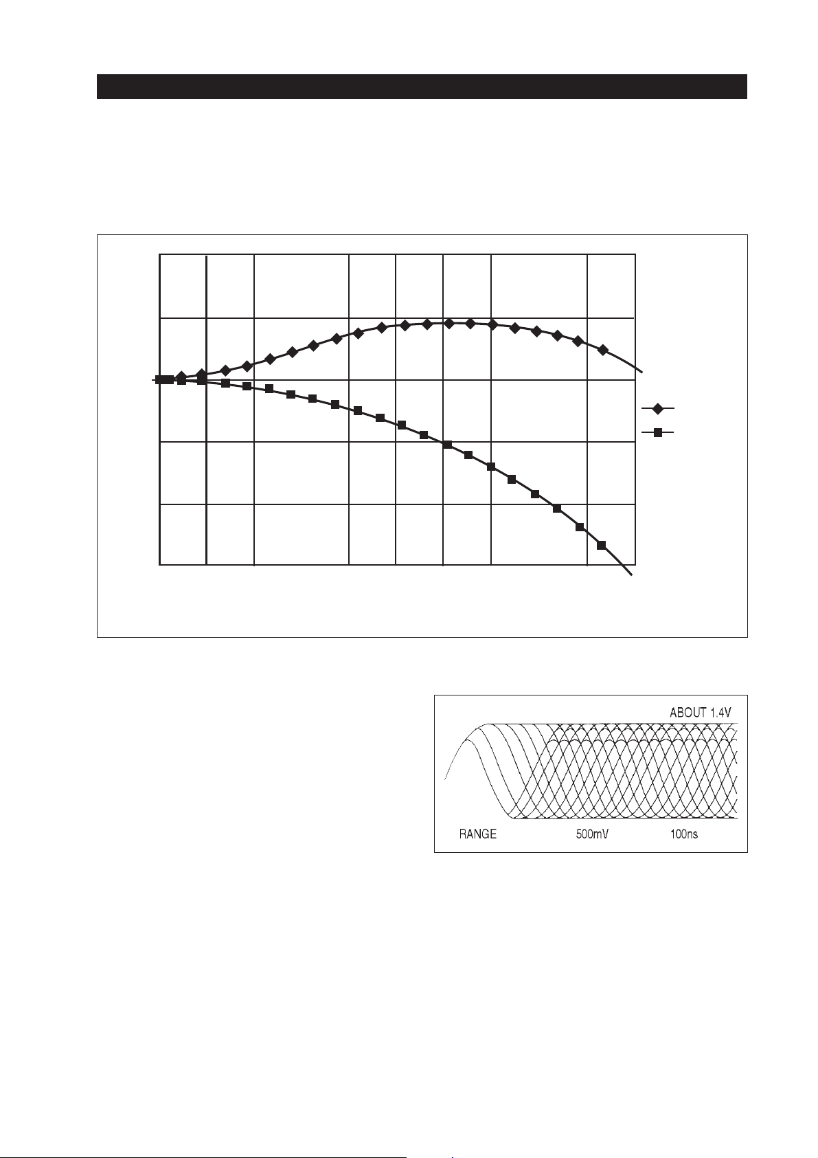
OPU, RF amplifier and servo processing
10
5
0
GAIN (dB)
–5
LPF+EQ
LPF
–10
–15
012345678 910
FREQUENCY (MHz)
Fig. 1-28
Theequalized signal is output at the pins 51 & 52 and
viaC053 &C054 senttothe inputsof afull-waverectifier (pin 53 & 54). There the signal is used for controlling the AGC level. The RF signal for data
processingis available at pin 57, from where it issent
to the processing IC806 on the MB-78 board. Figure
1-29 shows the DVD RF eye pattern. More informations are available in the “Operational Manual”.
Fig. 1-29
RF (eye pattern) waveform at DVD disc TK-47
board CN005 pin 26
25
Page 60
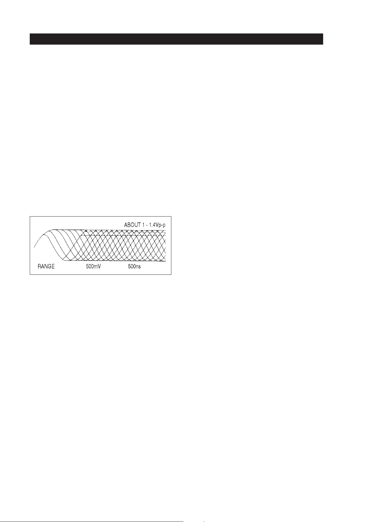
2.2.2. Creating the CD RF signal
OPU, RF amplifier and servo processing
The principle of generating the CD RF signal is the
same as we know from each CD Player; the sum
valueof all detector fields gives the RF level. Forthis
the PD1 and PD2 inputs at pin3&4isused. Inside
IC005 amplifying and equalization is peformed. In
this case the equalization is more like a bandpath filtering as a read out CD RF signal needs a bandwidth
ranging from approx. 196 kHz to 780 kHz. The RF
signalis availableat IC005pins21 and22; itissent to
IC806 on the MB-78 board. Figure 1-30 shows the
CD RF signal.
Fig. 1-30
2.3. The DVD focus servo
The focus error output, named FOUT at pin 46 of IC
506 is sent to the driver IC 363 (MB78-3/8board) input pin 26. The output pins 15 & 16 are controlling
the movement of the focus coil inside the DVD optical system.
The IP signal which is used for the SL / DL decision
is sent from pin37 of IC006 (TK-47 board) via
CN005, CN452 (MB-78-4/8 board) to IC452 pin 13.
Theoutputpin14 of the switch IC sends the PI signal
topin 3 of IC503which is a buffer.Nextthe PI signal
isforwarded totheinput pin21of theservoprocessor
IC506. For calculating a DEFECT signal the IP level
isalso availableat the defectdetector IC501 inputpin
3, which gives a feedback via the output pin 1 and Q
501 to the input pin 7 of the servo processor IC506.
IC locations:
• IC 006: TK-47 board
• IC 452: MB-78 -4/8 board
•
IC 503: MB-78 -4/8 board
•
IC 506: MB-78 -4/8 board
•
IC 363: MB-78 -3/8 board
The focus error signal is calculated inside the RF
amp IC006 (TK-47 board) and sent via the F.E. output IC006 pin 39, CN005, CN452 (MB-78-4/8
board)to the switch IC452pin3. This IC isswitching
between the DVD or the CD function. Next the F.E.
signal is sent from IC452 pin 4 to the buffer amp input pin 10 of IC 503. After level adjusting, the F.E.
signal is input to the servo processor IC 506 pin 26.
26
Figure 1-31 shows a rough block diagram of the focus servo.
Page 61
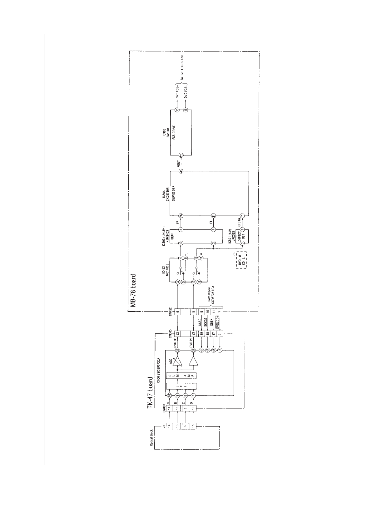
Fig. 1-31
27
Page 62
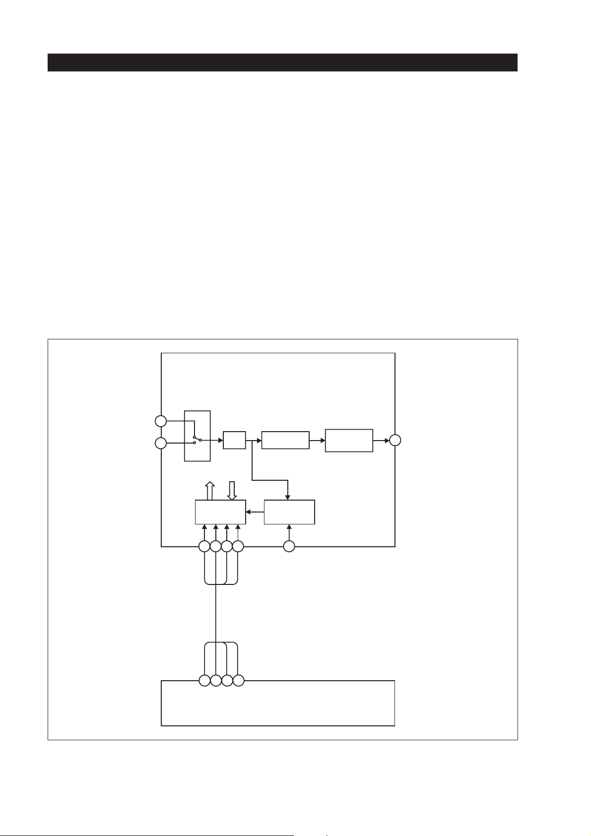
OPU, RF amplifier and servo processing
IC506 which includes the focus servo is a digital
servo processor. This means that every incoming error voltage or detected level like F.E. or PI will be
converted by an 8-bit A/D converter before it is input
tothe servo circuitinside. The servoICitself is working as a 16-bit processor. The output signal of the focusservo circuitat pin46 ofIC506 isa PWMsignal.
DIGITAL SERVO PROCESSOR (IC506)
ANALOGUE
MUX
26
FE
PI
21
A/D
SERVO DSP
Every function such as FOCUS SEARCH, FOCUS
JUMP or AUTO ADJUSTMENT and/or reference
value switchings are controlled by thesyscon IC805.
The syscon commands are interfaced by the IC 807
(S GATE ARRAY) which sends the commands with
a data bus (ID0-ID7)tothepins 56 - 63 of IC 506.
Adjustment data are stored by the syscon’s memory.
The syscon is working with one 1MB S-RAM
(IC802), one 8MB Flash Memory and one EPROM
(IC802, IC803 & IC801 / MB-78-8/8 board).
Figure 1-32 shows in a block diagram of the focus
servo part of IC506.
FOCUS PWM
GENERATOR
46
FOUT
28
CPU
INTERFACE
56 63 7
ID0-ID7
SYSCON via S-GATE ARRAY
IC805 IC807
FOK / FZC
& DEFECT
Fig. 1-32
Page 63
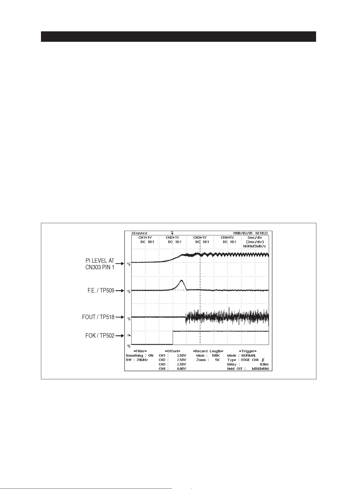
OPU, RF amplifier and servo processing
2.3.1. Focus search
The lens of the DVD optical system is moved up and
down in order to find the focussing point. The principle is the same like we know from CD. The focus
servo is switched from the search function to the
servo function when FOK & FZC is detected.
FOK detection is done by checking the level of the
PI signal, which should exceed a level of 2.75 V.
FZC is detected when the F.E. voltage is going
through zero.
The timing for switching ON the focus servo is detected by the servo logic which is checking the relation between FOK and FZC.
Figure 1-33 shows the S-curve and the levels which
are coming up from the F.E. signal during focus
search done with an SL disc. This is a real diagram
taken with a scope during focus search. You can observe that the focus search function stops when the
F.E. voltage is going through zero during FOK is at
“H”.
Figure1-34 shows the timing between FOK andFZC
when focus search is continued.
When a DL disc is used you will have two S-curves;
thereasonforthis is the reflected light of the two layers during the search movement of the optical lens.
Fig. 1-33
29
Page 64
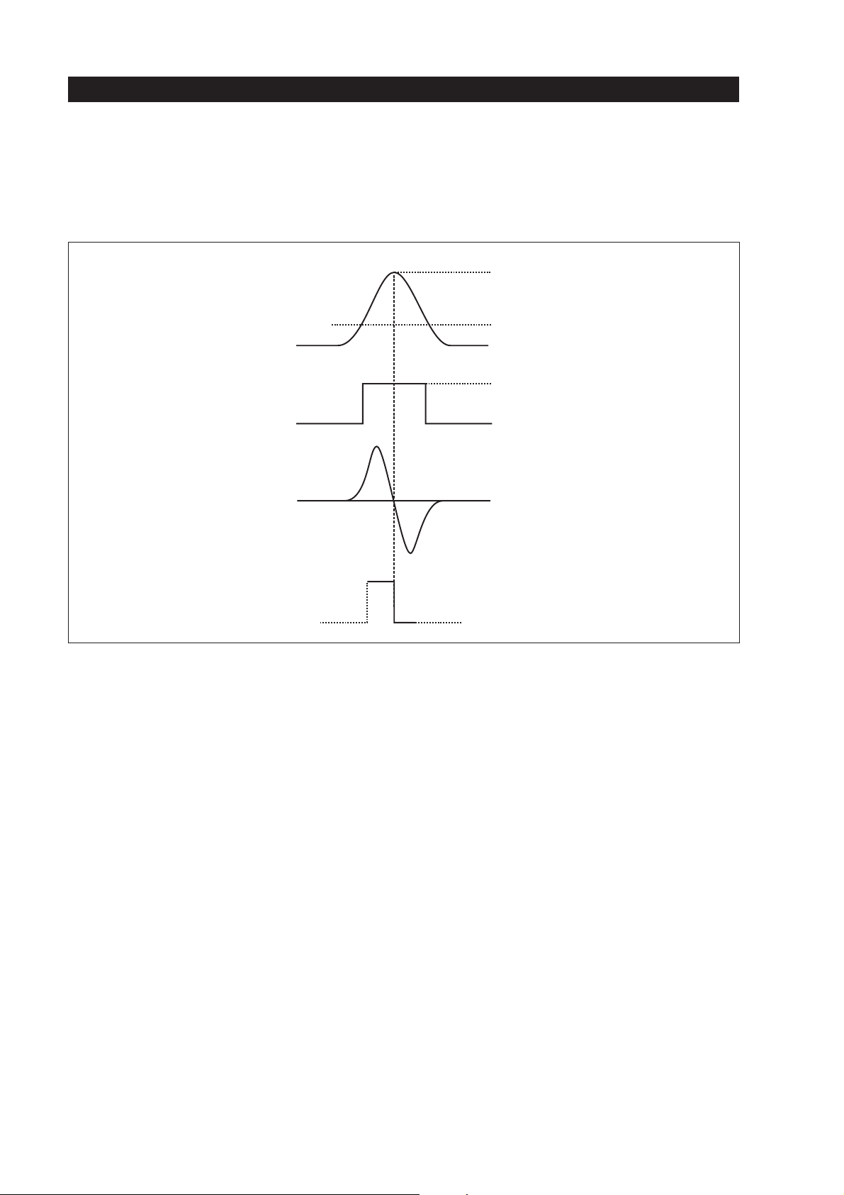
PI LEVEL
FOK SIGNAL
FE
OPU, RF amplifier and servo processing
REMAINS "H" IF
FOCUS SERVO
IS ON
FOK
THRESHOLD
REMAINS "H" IF
FOCUS SERVO
IS ON
FZC
Fig. 1-34
2.3.2. Automatic focus servo adjustment
The gain of the servo loop is automatically adjusted
every time when a disc is inserted. So the optimum
gain and EQ adjustment is available for each disc;
even if variations of the optical system occur they
will be corrected in this way.
A focus bias is added to the servo filter in order to
minimize offset problems caused by mechanical
variations of the µ-2-axis device. Also a voltage off-
set compensation based on a digital average measurement is available. All this is done automatically,
so that electrical and mechanical variations can be
corrected.
2.3.3. Focus (layer) jump
A focus jump is carried out when a DL disc is played
back. The focus jump is done between layer 0 and
layer 1 (= far end layer). See figure 1-35. At the beginningof a focus jump the servo loop is turnedOFF,
a kick voltage is applied to the focus coil of the µ-2axis device. The lens is moved higher to come in the
focus area of the second layer (which is layer 1, the
far end layer). During the jump the F.E. signal is
monitored; when a focus error voltage is available a
deceleration pulse is generated for stopping the lens
movement and the focus servo loop is turned ON
again and focussing is done. All these operations are
controlledby the servo DSP IC506. Figures 1-36 and
1-37 show the PI, F.E. and FOUT signals during focus jump.
30
Page 65
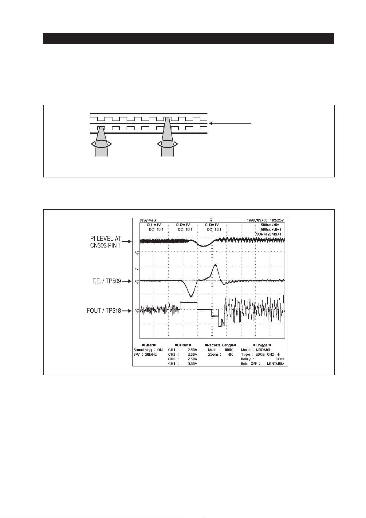
OPU, RF amplifier and servo processing
ONE-LAYER
PLAYBACK
TWO-LAYER PIT
ONE-LAYER PIT
THE SIGNALS ARE READ
TWO-LAYER
PLAYBACK
FOCAL POINT OF THE OPU
Fig. 1-35
2-layer disc readout method
ADHESIVE
(CLEAR PLASTIC)
BY CHANGING THE
Fig. 1-36
Focus jump from layer 0 to layer 1
31
Page 66
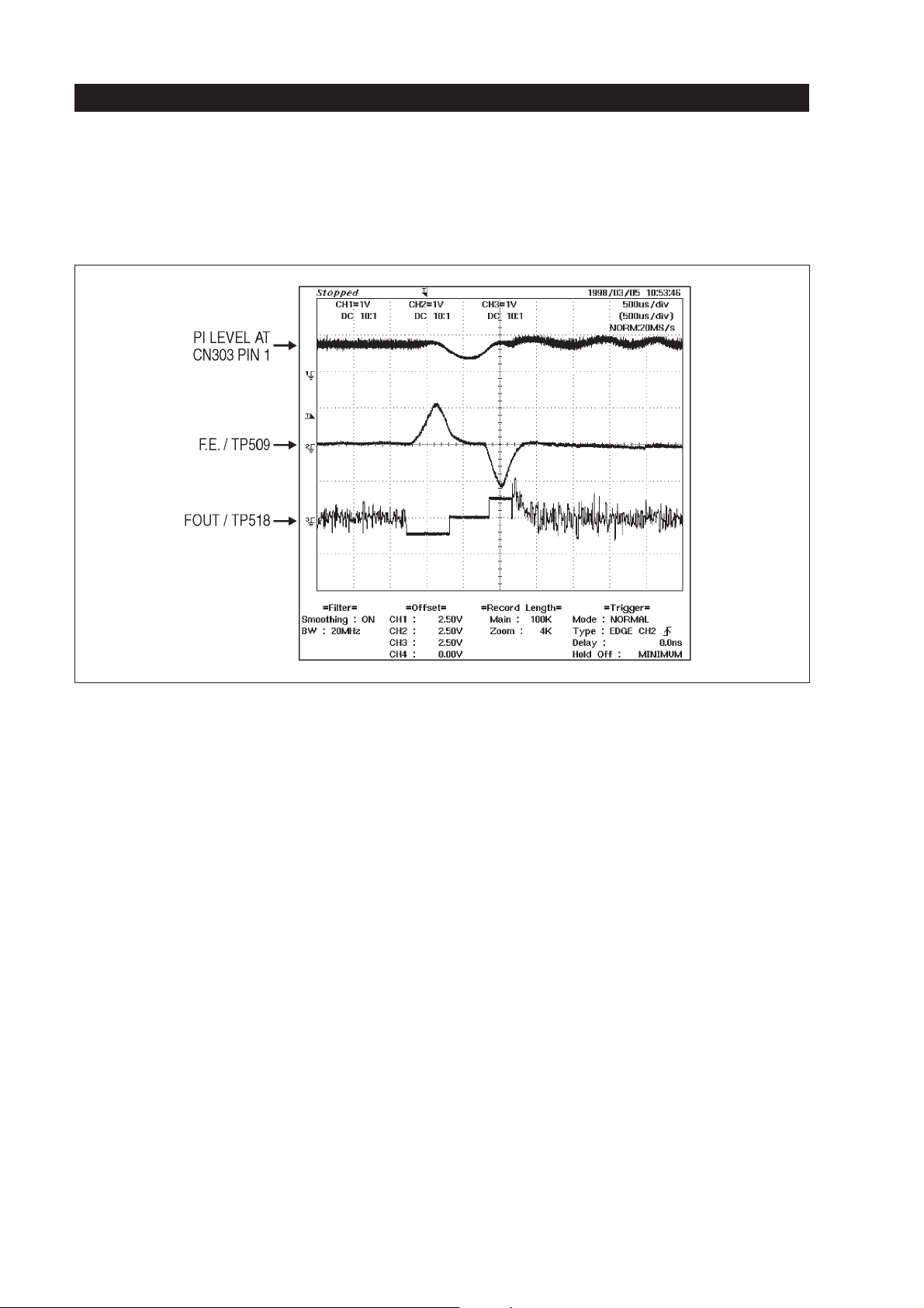
OPU, RF amplifier and servo processing
Fig. 1-37
Focus jump from layer 1 to layer 0
2.4. CD focus servo
Thefocus error signaliscalculated in theCDRF amp
IC005. Next it is sent from pin15 of IC005 to the
switch IC452 pin 5. During CD playback it is passed
through to the output pin 4 of IC452 via the buffer
IC503 (in pin 10 / out pin 8) to the input of the servo
DSP pin 26 of IC506.
The focus error signal is gain-, focus-bias and offsetadjusted as it is done during DVD playback.
The focus drive signal at the output pin 46 of IC506
(FOUT) is sent to the driver input pin 26 of IC363.
This driver IC is a 4-channel driver which is used for
driving the DVD and the CD focus coils. The CD focus coil is connected to pins 13 & 14 of IC363.
IC locations:
•
IC006: TK-47 board
•
IC452: MB-78-4/8 board
•
IC503: MB-78-4/8 board
•
IC506: MB-78-4/8 board
•
IC363: MB-78-3/8 board
In the following you will find a diagram taken with a
scope during CD focus search. As a CD will not have
a second layer a focus jump is not necessary.
The PI signal shown in the diagram above is extracted from the RF-DC level, which is available at
the RF amp IC005 pins 31 & 32. It is sent via CN005
fromtheTK-47board to the MB-78-4/8 board where
it is input to the switch IC452 pin 12. For CD playback it is output at pin 14 of IC452 as the PI signal.
Now it is connected to IC503 pin 3 and finally it
reaches the DSP input pin 21 of IC506 like we know
it from DVD playback.
32
Page 67
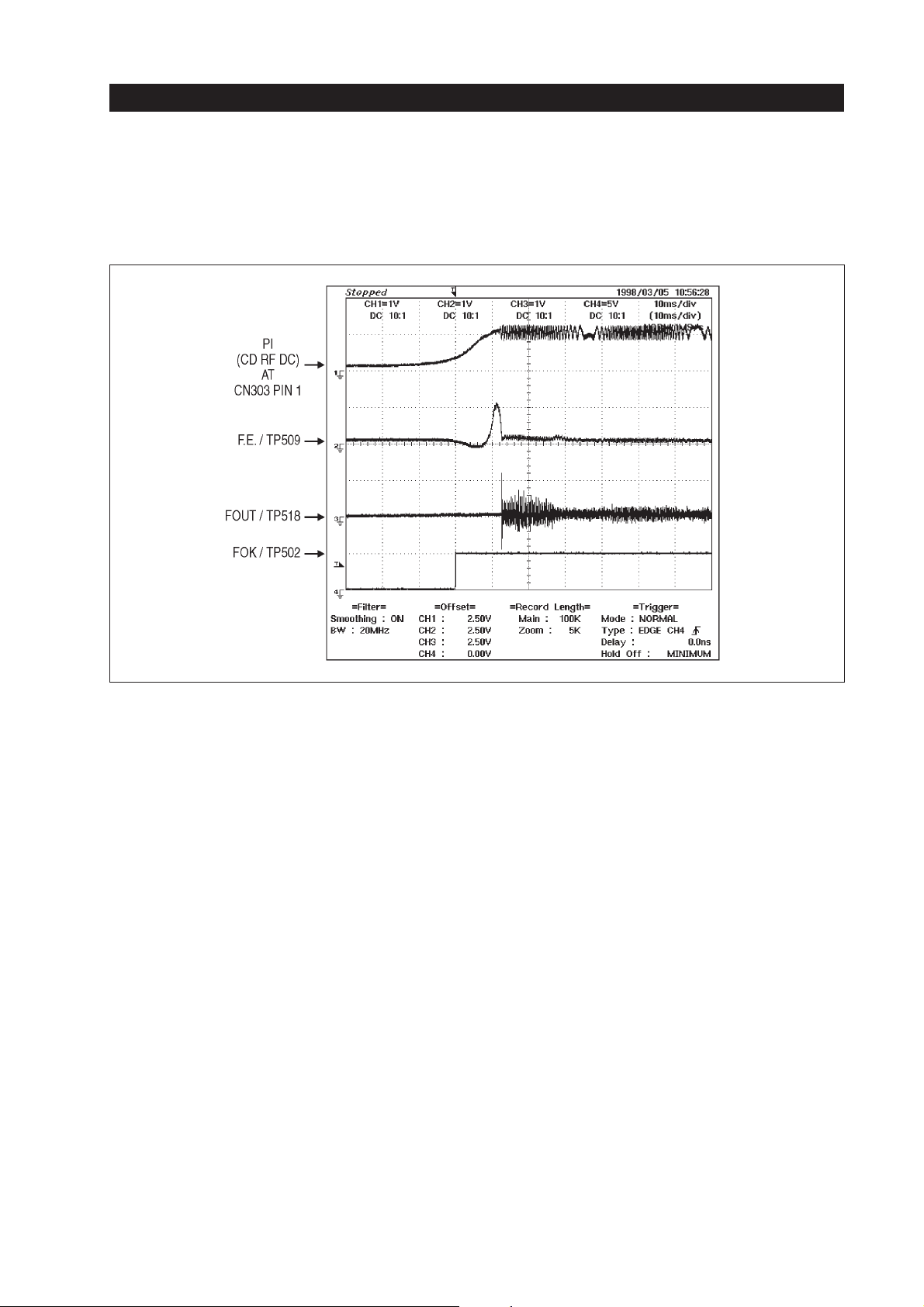
OPU, RF amplifier and servo processing
Fig. 1-38
CD focus search
2.5. DVD / CD switching
Partly the same ICs are used for DVD & CD focussing and tracking. Therefore a switching has to be
done. The switch IC452 is controlled by the CD /
DVD voltage at pins9&10forswitching the
DVD/CD-F.E. and T.E. voltages. At pin 11 of IC452
is a voltage for controlling whether DVD/CD-PI
switching available.
The distinction for the driver IC363 is done in relation to the MUTE signal at the input pins9&20of
IC363. See the following table.
IC363 Pin 9 Pin 20
DVD “H” “L”
CD & Video D “L” “H”
2.6. DVD tracking & sled servo
2.6.1. DVD tracking servo
The tracking error voltage is detected inside the RF
amp IC006. The gain and offset values are set by the
internalregister of IC006. The settings are controlled
by the syscon IC805 via IC804 (LGA).
TheT.E. signalisoutput frompin38 ofIC006;then it
enters the switch IC011 at pin 3. The switch is set to
outputthe T.E. signal at pin 4 when the set is in a normal PB function. The output is switched OFF when
the DVD-RF level is below approx. 200 mV
PP
(AC
component).
Next the T.E. voltage is sent to the MB-78-4/8 board
viaCN005 and CN452, where it is input to theswitch
IC452 at pin 1. When a DVD is played back it passes
throughto the output pin15of IC452. Now thesignal
is fed to the input pin 6 of the buffer IC503. The output pin 7 of IC503 is connected to the DSP’s T.E. input pin 24 of IC506.
33
Page 68
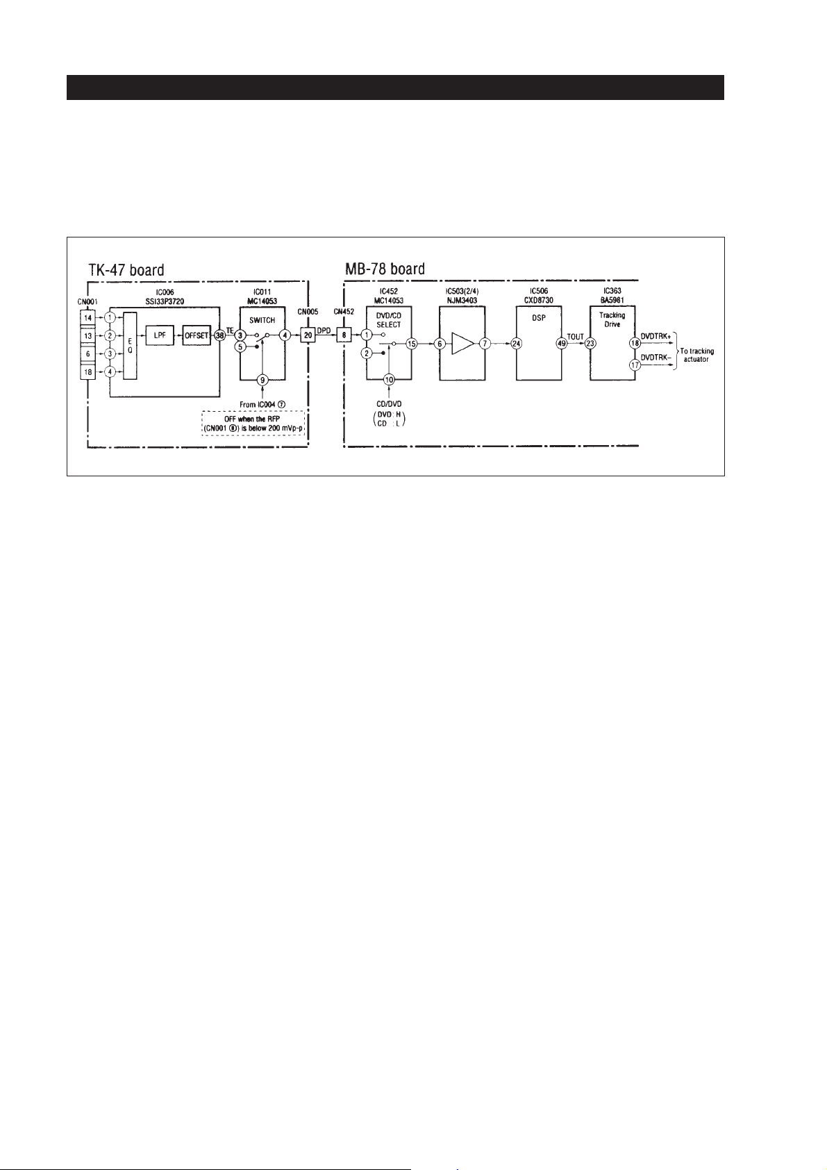
Fig. 1-39
OPU, RF amplifier and servo processing
The tracking drive signal at the output pin 49 of
IC506 (TOUT) is sent to the driver input pin 23 of
IC363. This driver IC is a 4-channel driver which is
used for driving the DVD and the CD tracking coils.
The DVD tracking coil is connected to pins 17 & 18
of IC363. The switching is done inthe same way like
it is mentioned in section “2.5. DVD / CD switching”.
IC locations:
•
IC006: TK-47 board
•
IC011: TK-47 board
•
IC452: MB-78 -4/8 board
•
IC503: MB-78 -4/8 board
•
IC506: MB-78 -4/8 board
•
IC363: MB-78 -3/8 board
Figure 1-39 shows the block diagram.
IC506 which includes the tracking servo is a digital
servo processor. This means that every incoming error voltage or detected level like T.E. will be converted by an 8-bit D/A converter before it is input to
the servo circuit inside. The servo DSP is a 16-bit
processor.The outputsignal ofthe focus servocircuit
at pin 49 of IC506 is a PWM signal.
Every function such as TRACK JUMP or AUTO
ADJUSTMENT and/or reference value switchings
arecontrolled by the syscon IC805. The syscon commands are interfaced by the IC807 (S GATE ARRAY)which sendsthe commands witha data bus(ID
0- ID 7)to pins 56 -63 of IC506. Adjustmentdata are
stored by the syscon’s memory. The syscon is working with one 1MB S-RAM (IC802), one 8MB Flash
Memory and one EPROM (IC802, IC803 & IC801 /
MB-78-8/8 board). See the block diagram in figure
1–40.
Automatic gain adjustment
The gain of the servo loop is automatically adjusted
every time when a disc is inserted. So the optimum
gain and EQ adjustment is available for each disc;
even if variations of the optical system occur they
will be corrected in this way.
34
Figure 1-40 shows the block diagram of the tracking
and sled servo of IC506. The sled servo will be discussed later.
Page 69
OPU, RF amplifier and servo processing
DIGITAL SERVO PROCESSOR (IC506)
TE
24
ANALOGUE
MUX
A/D
CPU
INTERFACE
56 63 7
ID0-ID7
SERVO DSP
SERVO DSP
SHOCK
DETECTOR
SLED PWM
GENERATOR
TRACKING PWM
GENERATOR
41
49
SOUT
TOUT
SYSCON via S-GATE ARRAY
IC805 IC807
Fig. 1-40
35
Page 70
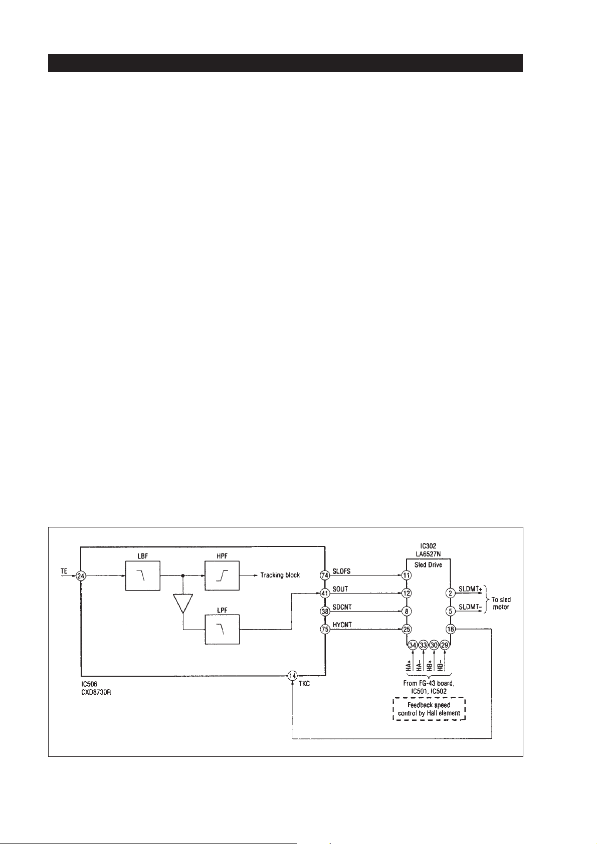
2.6.2. DVD sled servo in playback mode
OPU, RF amplifier and servo processing
During normal PB, when the focus and tracking
servo are switched ON, the sled servo controls the
sledmotor so that the objective lens of the DVD optical system always works approx. inthe middle of the
movable range of the tracking actuator. The sled errorvoltage (S.E.) is calculated inside the DSP IC506.
The principle is to equalize the T.E. signal so that
only the low-frequency AC components are used for
generating the SOUT driving voltage. It is available
at pin 41 of IC506. Next it is fed to the input of the
sled motor driver IC302 at pin 12. The sled motor is
controlled via the outputs pin2&5ofIC302. The
sled ON / OFF switching is also done inside IC506.
See also figure 1-40.
A switching between DVD or CD is not necessary as
this is done for the T.E. voltage which is the base for
the S.E. calculation.
The sled motor drive IC302 incorporates a speed
feedback control (motor rotational speed). For this
twoHallelementsare used (HA and HB). The output
is obtained from the sled motor board (FG-43 board)
as the differential output. The sled drive IC detects
the sled motor rotation with the Hall elements output
waveforms to form the speed feedback.
Inplayback mode theoutput drive voltage atpins 2 &
5 of IC302 is generated with respect to the sled error
signal(SOUT) at pin 12 and the sled motor rotational
speedfeedback composedby the inputsof the pins29
& 30, 33 & 34.
2.6.3. Sled forced operation control
For all other sled functions except playback (speed
search, etc.) a speed target signal (SDCNT) is input
frompin 38of IC506to thedriverIC302 pin8. Thisis
controlled by the syscon IC805 via IC804.
Forstopping thesled motorimmediately anoffset adjustment signal (SLOFS) is sent out from pin 74 of
IC506 to the input pin 11 of IC302 in order to adjust
the0 voltage at the motorterminals for stopping. Figure 1-41 shows a block diagram of the DVD sled
servo.
36
Fig. 1-41
Page 71
OPU, RF amplifier and servo processing
2.6.4. Tracking jump control
For carrying out one or more track jumps several
functions have do be done, special jump and brake
pulses have to be created and an exact timing is necessary.The DSP IC506 is controlling the track jumps
length between 1 - 1000 tracks per jump. Track
jumps up to a length of 32 tracks are controlled by
counting the number of tracks. For this the TZC
pulses are used. These track jumps are done with the
µ-2-axis device of the DVD optical system.
Track jumps with a length of more than 32 tracks are
done with the sled servo. The DSP controls the timing of the jump pulses. A 100-track jump needs a
pulse length of approx. 100 ms, which is controlled
by the DSP.
Figure 1-42 shows a DVD 1-track jump (FWD
&REV).
Infigure 1-42you canobserve the TZCsignal andthe
acceleration / deceleration pulses in the driving voltage TOUT. This 1-track jump is performed with the
µ-2-axis device only.
Fig. 1-42
37
Page 72
OPU, RF amplifier and servo processing
Figure 1-43 shows a 500-track jump done with the
sled motor mainly.
Ifa track jump isdone with more than1000 tracks the
IC506 sends out an SDCNT pulse to force the sled
operation. Neither the number of tracks nor the timingis controlled. Thismeans a 10000-trackjump will
force the sled motor to cover approx. 10000 tracks;
nothingchecks this exactly on theservo side. See figure 1-44.
38
Fig. 1-43
Page 73
OPU, RF amplifier and servo processing
Fig. 1-44
2.6.5. CD tracking servo
The tracking error voltage is detected inside the RF
amp IC005. The T.E. signal is output from pin 13 of
IC005.Next theT.E. voltageissent tothe MB-78-4/8
board via CN005 and CN452, where it is input to the
switch IC452 at pin 2. When a CD is played back it
passesthrough tothe outputpin 15of IC452.Now the
signal is fed to the input pin 6 of the buffer IC503.
The output pin 7 of IC503 is connected to the DSP’s
T.E. input pin 24 of IC506.
The tracking drive signal at the output pin 49 of
IC506 (TOUT) is sent to the driver input pin 23 of
IC363. This driver IC is a 4-channel driver which is
used for driving the DVD and the CD tracking coils.
TheCD tracking coil is connected tothe pins 11 & 12
of IC363. The switching is done inthe same way like
it is mentioned in section “2.5. DVD / CD switching”.
IC506 which includes the tracking servo is a digital
servo processor. This means that every incoming error voltage or detected level like T.E. will be converted by an 8-bit D/A converter before it is input to
the servo circuit inside. The servo DSP is a 16-bit
processor. The principle for generating the SOUT
signal is to equalize the T.E. signal so that only the
low-frequency AC components are used for generating the SOUT driving voltage. Every function such
as TRACK JUMP or AUTO ADJUSTMENT and/or
reference value switchings are controlled by the
sysconIC805. Theprinciples arethe same likebefore
mentionedin theDVD description.See the blockdiagram in figure 1-40.
39
Page 74

OPU, RF amplifier and servo processing
Automatic gain adjustment
The gain of the servo loop is automatically adjusted
every time when a disc is inserted. So the optimum
gain and EQ adjustment is available for each disc;
even if variations of the optical system occur they
will be corrected in this way.
Tracking auto level adjustment
This function operates only during CD and V CD
playback. When the T.E. level is too small due to
poorreflectivity ofthe disc thelevel will beincreased
by changing the input gain at IC005. The principle is
as follows.
After the dis is rotating and the focus servo is turned
ONthe peak-to-peak value of the T.E. traverse signal
is measured by IC506. The results are sent to the
syscon IC805 which determines the variable gain
amount and sends it back again to IC506. Next the
outputpins 11& 12 ofIC506 send gainvoltage levels
(PWM) which are formed to an analogue TEATT
voltage via IC503 (input pin 13, output pin 14). The
TEATT signal is now sent to pin 12 of IC005 to adjust the input gain. The adjustment range is 3 dB.
2.6.6. CD sled servo & jump control
The principle of the sled servo and jump controlling
is similar to the DVD servo and jump functions explained before. Only the internal settings for IC506
aredifferent. Alsothe trackjump lengthfor CDis different: trackjumps from1 -500 tracksare controlled.
From1-32tracksthe jumps are done with the 2-axis
device. The others are mainly done with the sled motor. From 33 - 500 tracks the controlling is done with
the timing of the track jump pulse width. If a track
jump with more than 500 tracks is done IC506 sends
out the SDCNT pulse to force the operation. See the
DVD explanation.
2.7. DVD spindle servo
The spindle servo generates two error signals: one
CLV speed error signal named “MDSO” and one
CLV phase error signal named “MDPO”. The spindle servo circuit is integrated in signal processor
IC806 (MD-78-7/8 board) and the error signals are
available at pin 43 (MDSO) and pin 47 (MDPO).
They are added and LPF-filtered in IC301 pins2&5
(MD-78-3/8 board). The spindle error signal SPERR
is coming out at pin7 of IC301. The driver IC303 receives the error signal atpin 13. The spindle motoris
a BSL motor with three poles; it receives from IC303
theU, V, W drive signals(outputpins1&34-30);as
is usual for a BSL motor also an FG feedback is sent
from the motor’s Hall elements to the driver IC.
Pins8&9ofIC303 areused for controllingthe acceleration and deceleration as follows:
Control mode Input signals
Pin 9 Pin 8
Acceleration “H” “L”
Deceleration “H” “H”
No control “L” “H”
Gain switching in relation to the disc size (8 or 12
centimeters) is done via the input pin 11 of IC303.
2.8. CD spindle servo
As the RF signal is processed inside IC806 the outlineoftheCD spindle servo is the same as the one for
DVD. Figure 1-45 shows the block diagram of the
spindle servo.
40
Page 75
OPU, RF amplifier and servo processing
Fig. 1-45
2.9. Tilt control / tilt servo
The tilt servo is using the SKEW sensor mounted on
the OPU. The tilt control is performed at the start of a
DVD or CD playback.
The SKEW sensor output of the OPU is input at pins
20& 21 of IC006 (DVD-RFamp / TK-47 board). Afteramplification andintegration the tilterror signal is
output at pin 26 of IC006, named TIERR. A second
tilt error signal is output at pin 23; it is named TIE.
From the TC-K47 board the signals are sent via the
MD-78-4/8 board to the MD-78-3/8 board.
IC455 is working as window comparator; for this it
receives the TIE voltage at pin 6. Pin 7 of IC455 is
controlling Q452. When the transistor is switched
OFFthe tiltservo goes OFFto form adead band.This
is done when the TIE voltage drops below 2.5V±50
mV.
When Q452 is ON the tilt error voltage (TIERR) is
input to pin 21 of IC361. The tilt motor is connected
to the driver output pins5&6ofIC361. The tilt motor is a normal DC brush motor type.
41
Page 76
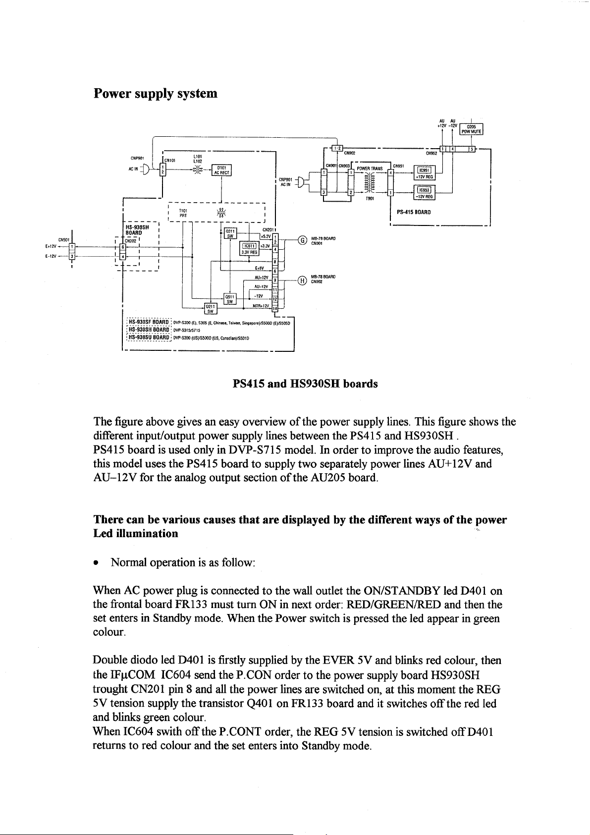
Page 77
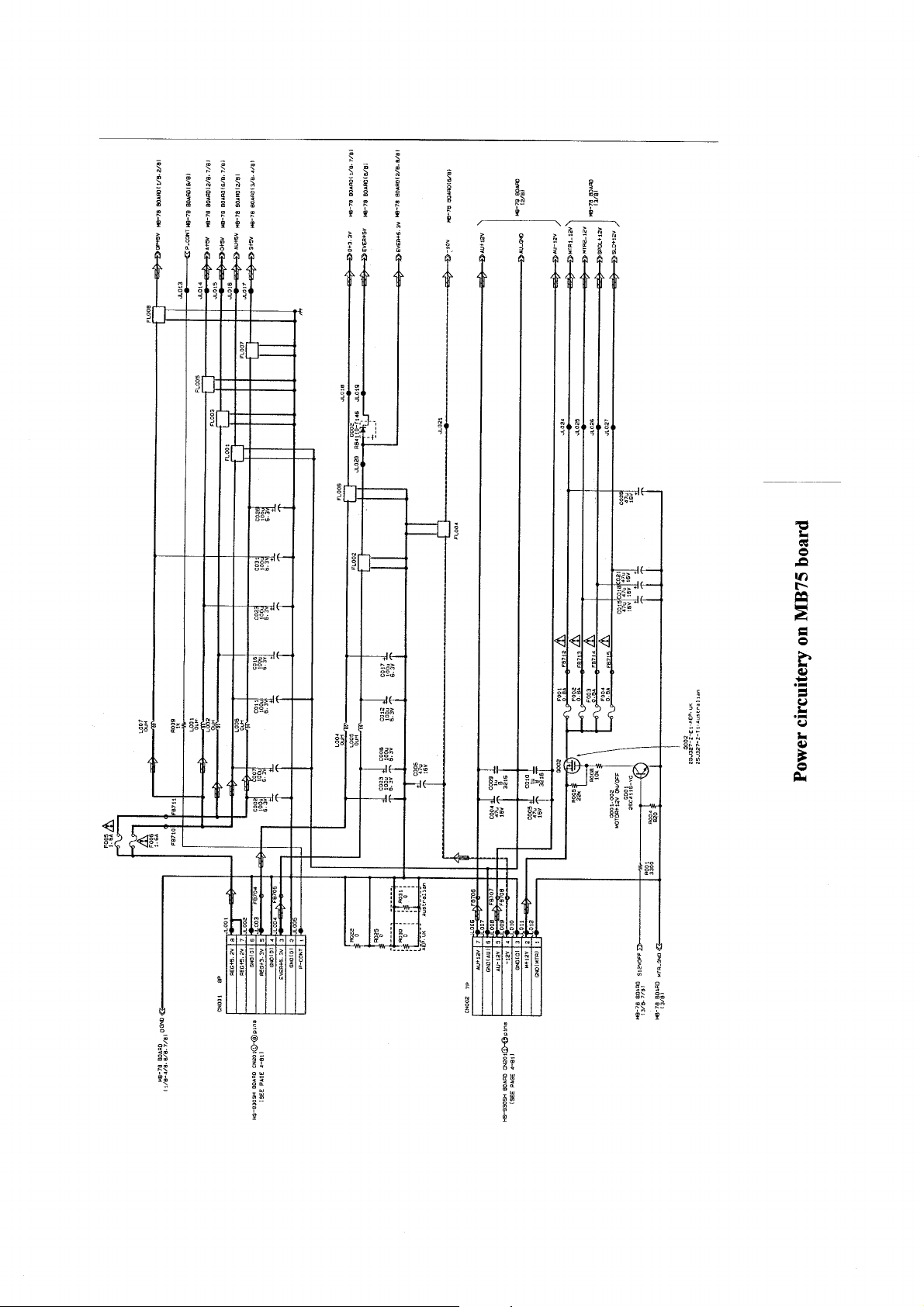
Page 78
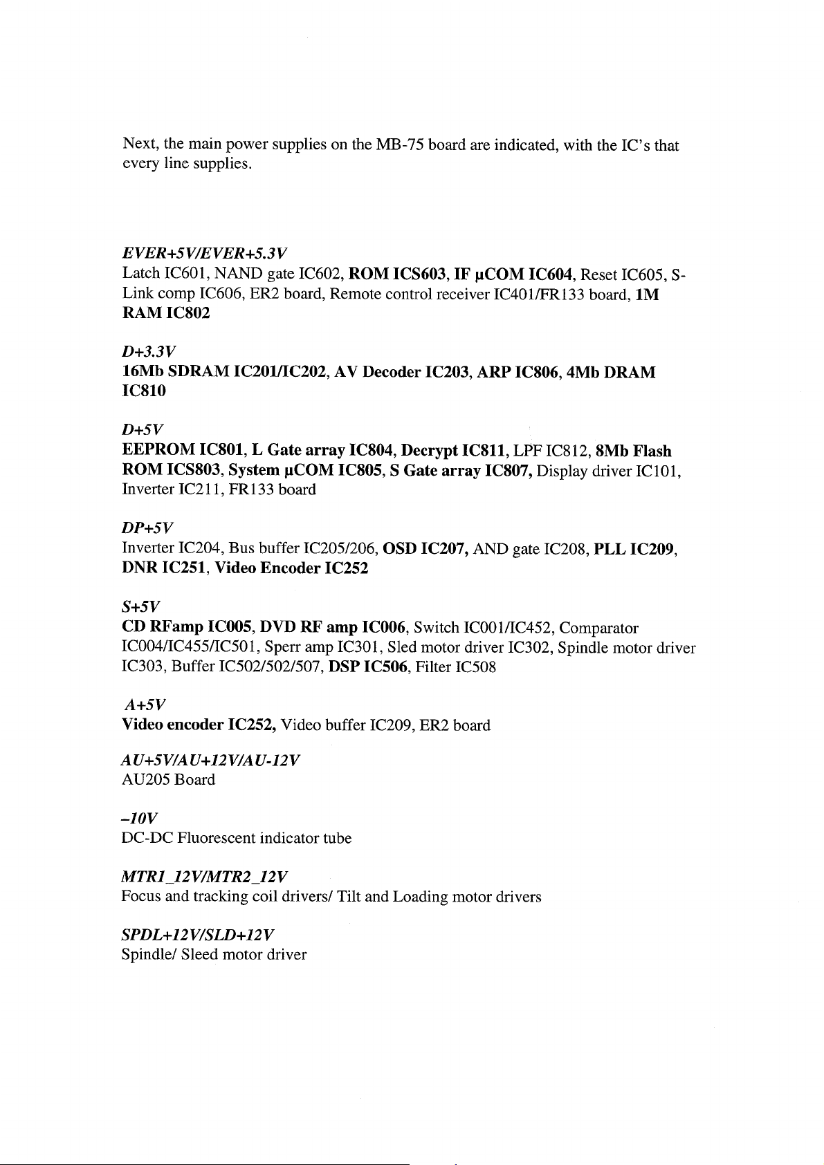
Page 79
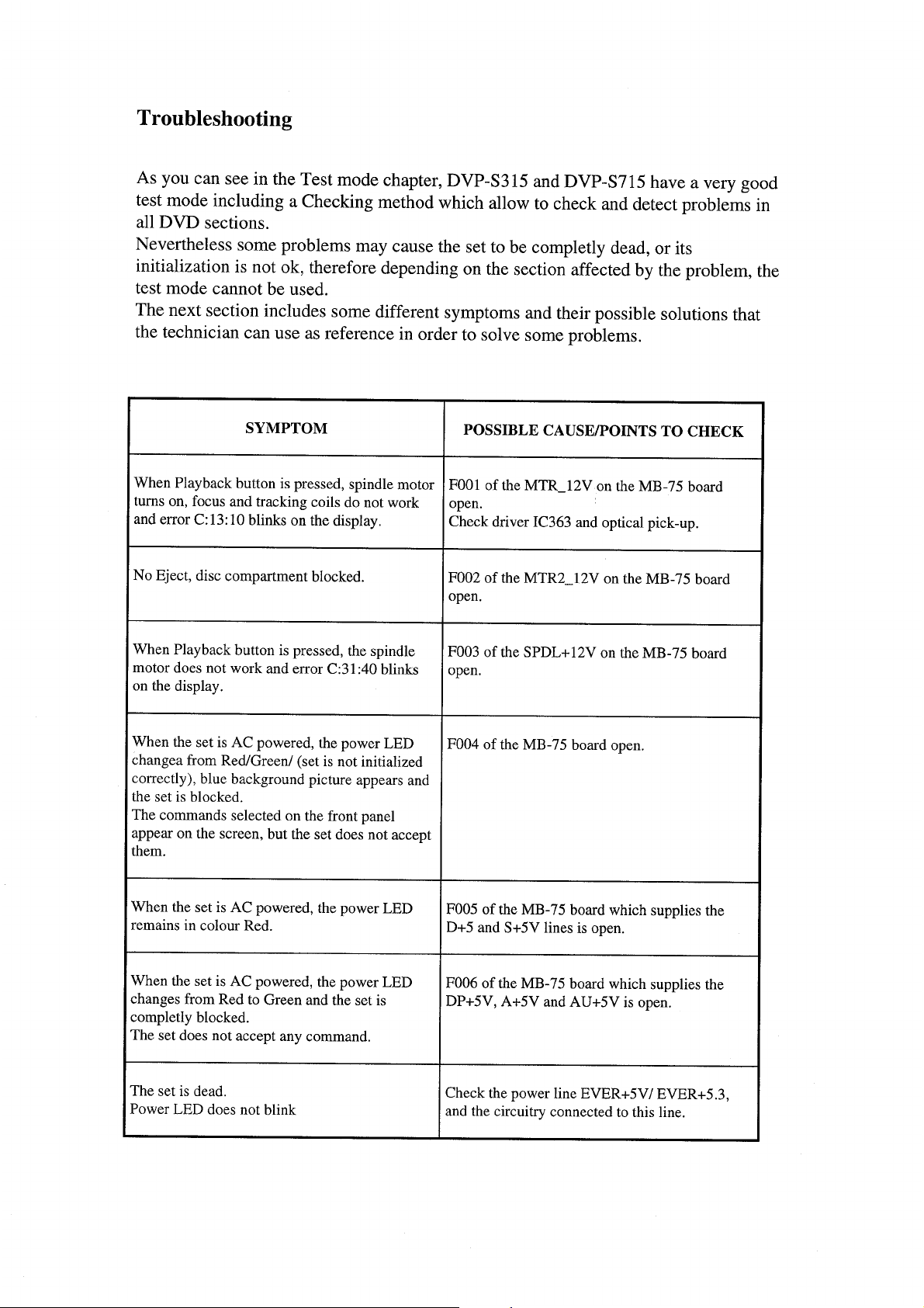
Page 80
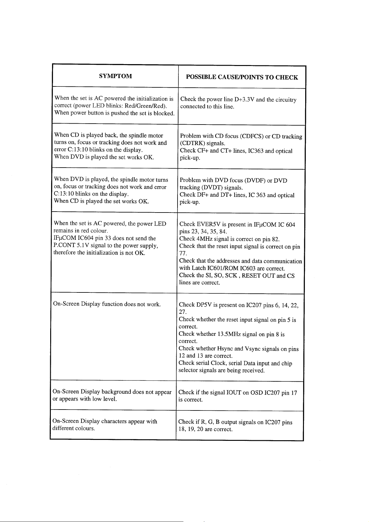
Page 81

Page 82

T echnicalT raining
Eur opeanT echnicalT raining
ServiceEngineering
CustomerRelations&ServiceEur ope
 Loading...