

Page 1

Remote Control
Unit
3-865-447-04(1)
取扱説明書
Operating Instructions Page 13
Mode d’emploi Page 23
Bedienungsanleitung Seite 33
Istruzioni per l’uso Pagina 43
警告
ページ
3
電気製品は、安全のための注意事項を守らな
いと、火災や人身事故になることがありま
す。
JP
GB
FR
DE
IT
この取扱説明書には、事故を防ぐための重要な注意事項と製品
の取り扱いかたを示しています。この取扱説明書をよくお読み
のうえ、製品を安全にお使いください。お読みになったあと
は、いつでも見られるところに必ず保管してください。
DSRM-20
1998 by Sony Corporation
Page 2
目次
安全のために
ソニー製品は安全に充分配慮して設計されています。しか し 、電気製品は、まち
がった使いかたをす ると 、火災や感電などに より 死亡や大けがなど人身事故につ
ながることがあり、 危険です。
事故を防 ぐため に次のことを必ずお守りください。
安全のための注意事項を守る
このページの注意事項をよくお読みください。
定期点検をする
5年に1度は、内部の点検を、お買い上げ店また はソ ニー のサービス窓口にご依頼
ください (有料 )。
故障したら使わない
すぐに、お買い上げ店またはソニーのサービス窓口にご連絡ください。
万一、異常が起きたら
1 電源コードや接続ケーブルを抜く。
煙が出たら
•
異常な音、においが
•
したら
内部に水、異物が
•
入ったら
製品を落としたり
•
キャビネットを破損
したときは
/
2 お買い上げ店またはソニーのサービ
ス窓口に連絡する。
警告表示の意味
取扱説明書および 製品で は、次の
ような表示をしています。表示の
内容をよく 理解してから本文をお
読みください。
警告
この表示の注意事項を守らない
と、火災や感電などにより死亡や
大けが など人身事故につ ながるこ
とがあ ります。
注意を促す記号
火災
行為を禁止する記号
分解禁止
感電
下記の注意を守らないと、
警告
感電火災
火災や感電により死亡や大けがにつながることがあります。
分解や改造をしない
分解や改造をすると、火災や感電、けがの原因となる こ とがあ り ます。
内部の点検や修理は 、お買い上げ店またはソニー のサービ ス窓口にご依頼くださ
分解禁止
い。
2
Page 3

日本語
目次
概要
概要 ...........................................................................................
各部の名称と働き .........................................................................
接続 ...........................................................................................
操作 ...........................................................................................
ジョグ / シャトルサーチ................................................................................ 6
頭出し.........................................................................................................7
録画情報の表示....................................................................................... 10
仕様 .........................................................................................
保証書とアフターサービス .........................................................
3
4
5
6
11
11
JP
日
本
語
リモートコントロールユニットDSRM-20は、ビデオカセットレコーダーDSR-40用のリモートコ
ントロールユニットです。
本機を接続すると、DSR-40に、次の機能が付加されます。
シャトルサーチ
ジョグ
/
シャトルダイヤルにより、静止画および−14〜+14倍速の再生画を、ジョグダイヤルによ
り、静止画および−2〜+2倍速の再生画を見ることができます。
頭出し機能
テープに記録されたインデックス信号や、カセットメモリーに記録された日付やフォト信 号を
使って(カ セットメモリー付きカセッ トの場合)、テープの特定の位置を素早く頭出しすること
ができます。
録画情報の表示
DSR-200/200A/PD1/PD100などのカムコーダーでの撮影に使用したテープを再生してい
る とき は、テープに記録されたカムコーダー情報を表示するこ とができます。
3
Page 4
各部の名称と働き
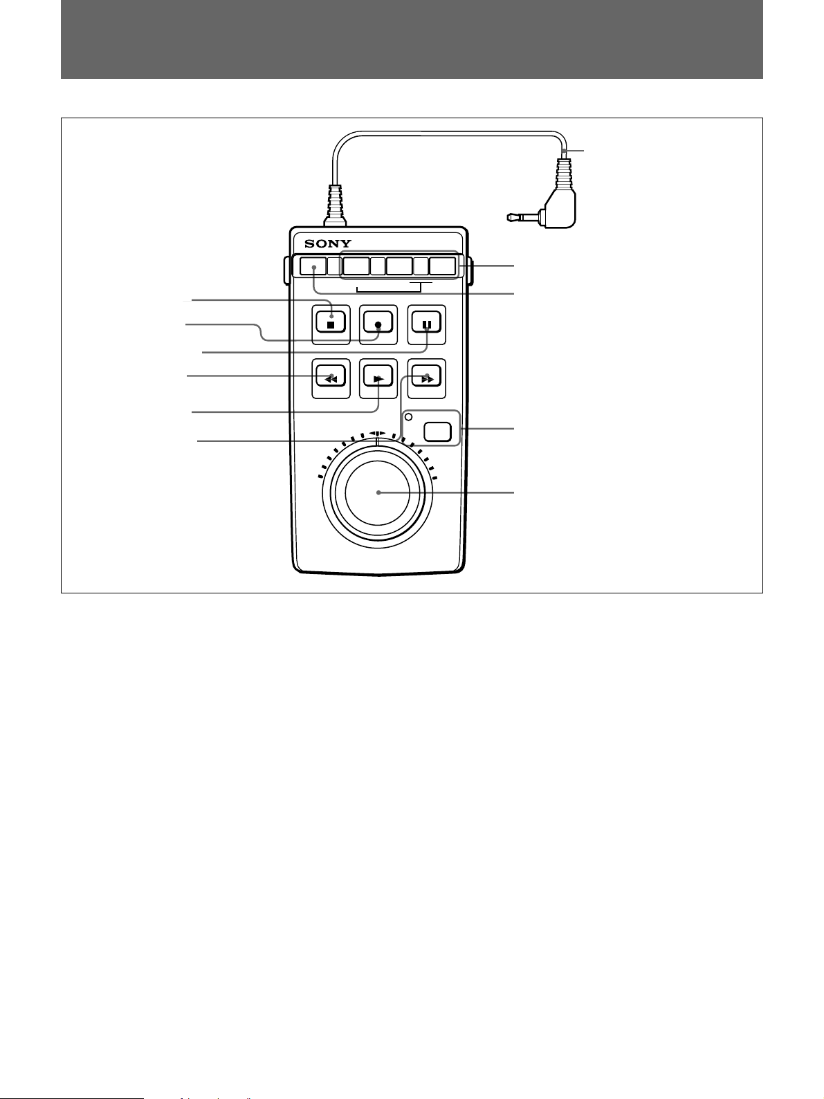
!¡ 接続ケーブル
DATA CODE SEARCH MODE
1
2
3
4
5
6
1
STOP ■ (停止)
STOP
ボタン
REC
PAUSE
ボタン
REW
PLAY
F FWD
ボタン
ボタン
ボタン
ボタン
ボタン
STOP REC
REW
PLAY
テープの走行を止めるときに押します。
2
REC ● (記録)
ボタン
記録を行うときは、このボタンを押してVTRを記録一時停止状態
( レックポー ズ)にしてから、PAUSEPボタン3を押し ます。
3
PAUSE P (
一時停止)ボタン
記録/再生を一時停止します。再度押すと一時停止が解除されま
す。
4
REW 0 (
巻き戻し)ボタン
VTRが停止しているときに押すと、テープの巻き戻しが行われま
す。
再生/巻き戻し中に押すと、押 している間再生画を見ながらテープ
を巻き戻すこ とができ ます。
=
=
PAUSE
F FWD
JOG/SHUTTLE
6
F FWD ) (
0
SEARCH MODE
9
DATA CODE
8
JOG/SHUTTLE
インジケーター
7 サーチダイヤル
早送り)ボタン
ボタン
ボタン
ボタン
/
VTRが停止しているときに押すと、テープの早送りが行われます。
再生 /早送り中に 押すと、押している間再生画を見ながらテープを
早送りすることができます。
7 サーチダイヤル
右へ回すと順方向の再生、左へ回すと逆方向の再生になり
ます。
シャトルダイヤル
:ダイヤルを回して任意の位置で止める
(外側)
と、 その位置に対応した速度(−14〜+14倍速)でテープが
再生されます。中央の位置では静止画になります。
ジョグダイ ヤル
:ダイヤルの回転速度に応じた速度
(内側)
(−2〜+ 2倍速)でテープが再生されます。
ご注意
ジョグダイヤ ル は 、 シャトルダイヤルが中央のクリッ クする位置
にあると きだけ働きます。
5
PLAY ( (再生)
ボタン
テープを再生するとき押します。
4
Page 5
8
JOG/SHUTTLE (
ター
ジョグ /シャトル モ ード でテ ープ を再生す るとき押します。
押すとインジケーターが点 灯し、 DSR-40はジョグ/シャトルモー ドに
なります。ジョグ /シャトル モードを解除するときは、任意のテープ走
行ボタンを押 し ます。
ジョグ/シャトル)ボタン/インジケー
0
SEARCH MODE (
場面を頭出しするときに押します。
◆詳しくは、7ページの「頭出し」をご覧く ださい。
!¡ 接続ケーブル(ステレオミニプラグ付き
DSR-40のCONTROLS端子に接続します。
サーチモード
)=/
+ボタン
)
9
DATA CODE (
録画情報をモニター表示します。
◆詳しくは、10ページの「録画情報の表示」をご覧く ださい。
データコード)ボタン
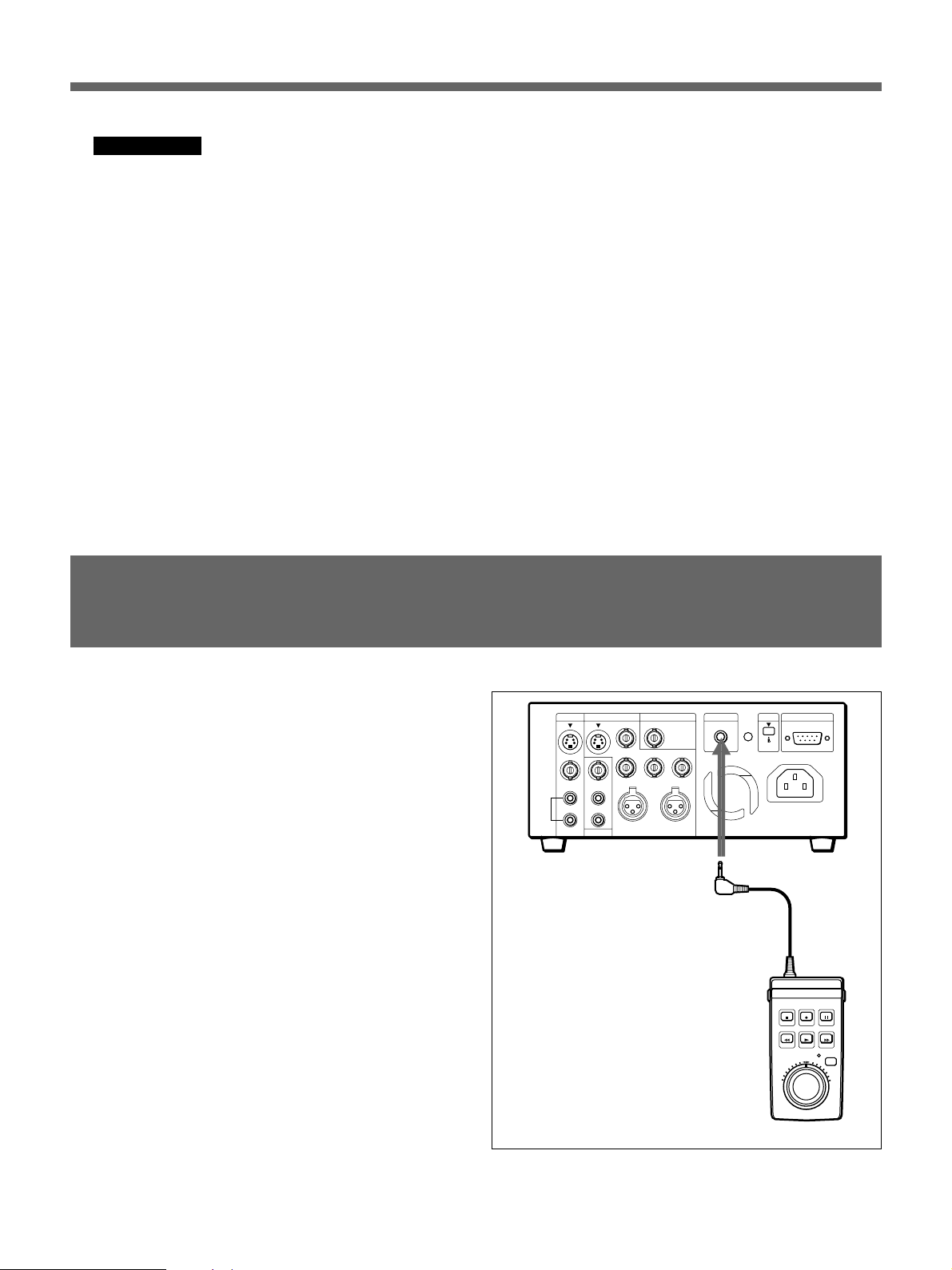
接続
本機をDSR-40のCONTROLS端子に接続します。
本機をDSR-40に接続すると、DSR-40から本機に、自動的に電源
が供給されます。
CONTROL S
端子
DSRM-20
5
Page 6

操作
ジョグ/シャトルサーチ
本機のテープ走行ボタンは、DSR-40のテープ走行ボタンと同じ働きをします。記録、再生、
早送り、巻き戻し、一時停止を本機からリモー トコン トロールすることができます。
サー チ ダイヤ ル を 使って、ジョグモード、 シャトルモー ドでのサーチ操作を行います。
ジョグモード:ジョグダイヤルの回転速度に応じて、静止および−2〜+2倍速の再生
が可能。
シャトルモード:シャトルダイヤルの位置(ダイヤルを回す角度)に応じて、静止および
−14〜+14倍速の再生が可能。
ご注意
電源を入れた直後は、シャトルダイヤルを一度中央位置にしてから操作してください。
DUP
COUNTER
AUDIO
SELECT
TC
CH-1/2
CH-3/4
MONITOR
MIX
TIMER
REMOTE
REPEAT
OFF
MENU
REC
LOCAL
SET
CONTROL S
端子
INPUT
SELECT
COUNTER
REMAIN
TAPE
1
2-
1)
2-
2)
DSRM-20
1 JOG/SHUTTLEボタンを押し、ジョグ / シャトルモードにする。
JOG/SHUTTLEインジケーターが点灯します。
2 ジョグモードでサーチするには
シャトルダイヤルを中央のクリッ クする位置にする。
1)
ジョグダイヤ ルを回 す。
2)
ダイヤルの回転速度に応じた速度の再生画が現れます。
回転を止めると静止画になります。
6
Page 7
µ
シャトルモードでサーチするには
シャトルダイヤルを回す。
ダイヤルを回した角度に応じた速度の再生画が現れます。ダイヤルを中央のクリック
する位置にするとテープ走行が止まり、静止画になります。
シャトルモードを解除するには
ジョグ
/
任意のテープ走行ボタンを押します。
JOG/SHUTTLEインジケーターが消 灯し、押したボタンに対応して動作します。
頭出し
本機を使って、以下の頭出しができます。
−録画の開始位置を探す:インデックスサーチ
−撮影日で探す:日付サーチ
−フ ォトモー ド撮影の場面を探す:フォト サーチ
カセットメモリーの付いたカセットで頭出しするには
カセットメモリーの付いたカセットを使用すると、記録した日付の順に場面の一覧が表示さ
れます。表示 さ れた一覧を使って頭出 しができます。
1 SEARCHMODEボタンを押して、頭出しの種類を選ぶ。
録画日時順に場面の一覧が表示されます。
インデックスサーチを選んだ場合
2 =/+ボタンを押して、頭出しする場面を選ぶ。
選んだ場面まで巻き戻しまたは早送りし、通常の再生(フォトサーチの場合は一時停
止)になります。
7
Page 8

操作
INDEX 0
SEARCH
カセットメモリーのないカセットで頭出しするには
カセットメモリーのな い カセッ トを使用 しているとき は、DSR-40のメニューの「CASSETTE
MEMORYSEARCH」の設定に関わ らず、現在のテープ位置から前後の場面が順に頭出
しされます。
◆ メ ニュ ー操作については、DSR-40の取扱説明書をご覧ください。
1 SEARCHMODEボタンを押して、頭出しの種類を選ぶ。
インデックスサーチを選んだ場合
頭出し信号について
2 =/+ボタンを繰り返し押して、頭 出しする場面を選ぶ。
押した回数だけ先または前の場面が頭出しされます。いく つ先(前)の場面が数字で
表示されます。「0」になる まで巻き戻しまたは早送りされると、通常の再生(フ ォトモー
ドの場合は一時停止)にな ります。
頭出し信号は「RECボタンを押して録画を始めたとき」に付きます。
3種類の頭出し信号があります。頭出し信号はテープ上とカセットメモリーに 記 録され ます
が、カセットメモリーの有無や、録画 した機器によっ て記録さ れ る 信号が異なり ま す。信号
がないときは、そ の信号を使った頭出しはで きませんので、ご注意ください。
デジタルカムコーダー(
信号の種類 カセットメモリー テープ上
インデックス信号
日付信号 記録する 記録する
フォ ト信号 記録する 記録する
a)停止状態から録画を開始したときのみ記録されます。
a)
DSR-200/200A、DSR-PD100
記録しない 記録しない
)で撮影したとき
8
Page 9
カセットメモリーの容量について
DSR-40
信号の種類 カセットメモリー テープ上
インデックス信号
日付信号 記録しない 記録する
フォ ト信号 記録しな い 記録しない
a)停止状態から録画を開始したときのみ記録されます。
で録画したとき
a)
記録する 記録する
ご注意
DSR-40で録画したとき、インデックス信号に曜日情報は含まれません。
• マーク表示のあるカセットを使うと、 DSR-40では頭出し信号を135個まで記録できま
す。ただし 、一本のテープにインデックス信号、日付信号、フォ ト信 号が混ざって 記 録され
ているときは、この数値は変化します。DSR-40では、カセットメモリー 1 6 キロビットまで対
応 してい ます。
• カセットメモリーに入り きらない場面を頭出しするときや、テープ上の位置の順番に頭出し
したいと きは、メニューの「CASSETTEMEMORYSEARCH」を「OFF」にしてください。
カセットメモリーのないカセッ トと同じ頭出 しができ ます。
◆ メ ニュ ー操作については、DSR-40の取扱説明書をご覧ください。
ご注意
• 頭出し用の信号は録画を開始した時点で記録されます。開始位置の上に他の場面を録
画した場合、カセットメモリー上の元の画面の頭出し信号は消え、元の画面は頭出しでき
なく なります。
インデックス信号
の開始位置
ABC
DをB
に録画すると…
の頭出しはでき
B
ません。
ABCD
• 頭出し信号のみを後から付けるこ と はできません。オートリピートのためにイ ンデックスを付
けたいとき は、イン デックスを付けたい 位 置 から新たに 録 画し てください。
• 頭出し信号のみを後から消すこ とはでき ません。オートリピートのためにイ ンデックスを消
したいと きは、メニューの「INDEXWRITE」を「OFF」に設定 してから、消したいイ ンデ ッ
クス の上 に録画して ください。
• ソニー製以外のデジタルビデオで記録されたテープでは、頭出しが行えないことがありま
す。
◆ メ ニュ ー操作については、DSR-40の取扱説明書をご覧ください。
9
Page 10
操作
録画情報の表示
ソニー製のデジタルカムコーダーDSR-200/200A、DSR-PD100で撮影したテープには、カ
ムコーダー情報 (シャ ッタ ースピー ド、 アイリス、ホワイ トバランス、プログラム AE モー ド、ゲ
イン) が記 録されます。 これらを再生中に表示して確認できます。
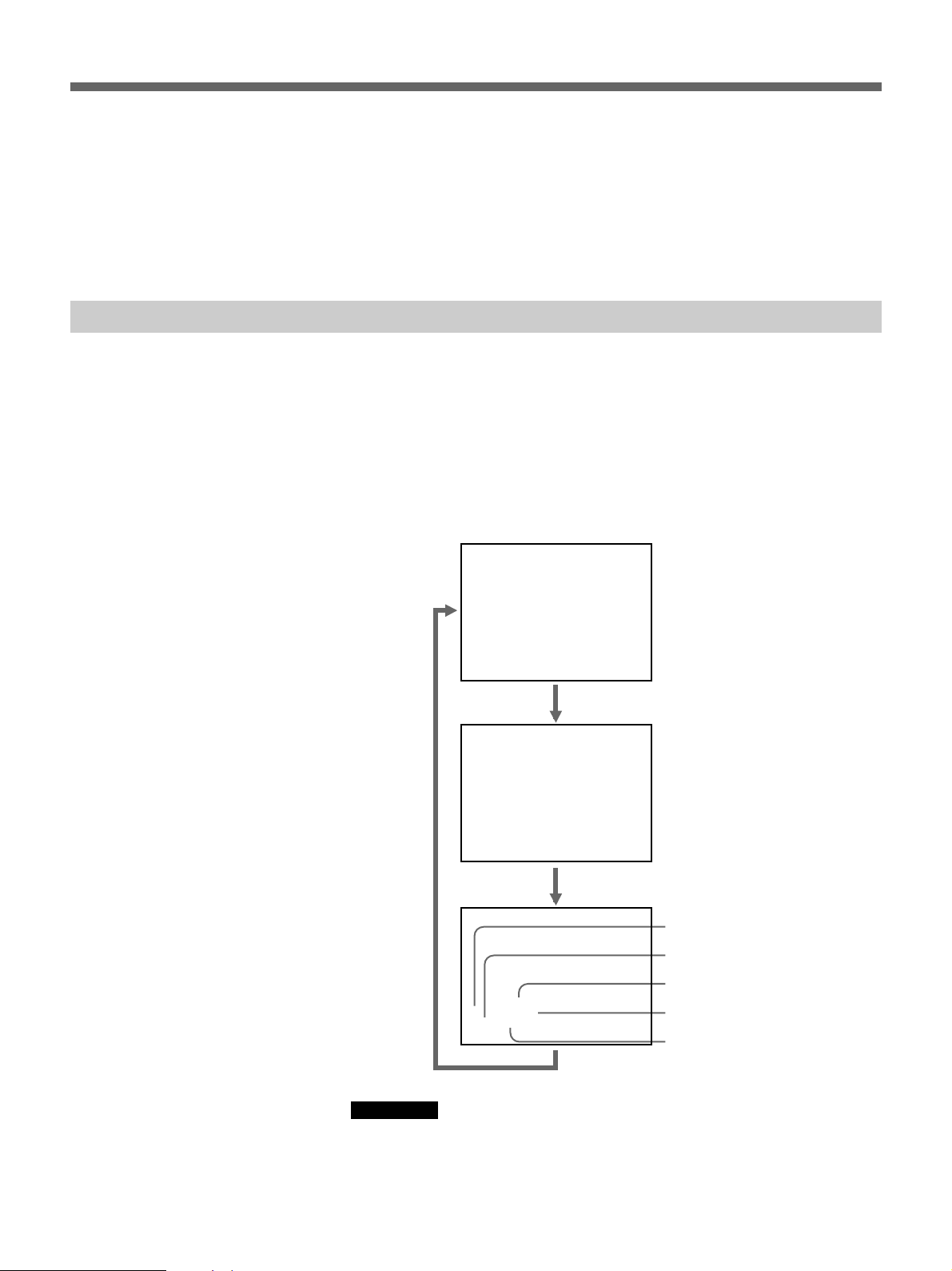
再生中に本機のDATACODEボタンを押してください。 押すたびに、表示は通常画面n
「日付情報」n「カ ム コーダー情報」n 通常画面……の順に切り換わります。
通常画面
日付情報
1999 / 12 / 25
12:59 AM LINE
カムコーダー
情報
シャッタースピード
アイリス
ホワイトバランス
AWB
60 MANUAL
F 1.6 0 dB
プログラムAEモード
ゲイン
ご注意
• カメラ情報が記録されていない場合は、画面に「---」が表示されます。
• DSR-40でのカムコーダー情報の表示は、カムコーダー側の表示と一部異なります。
10
Page 11

仕様
リモートコントロール ステレオミニプラグ(接続ケーブル付き、
ケーブル長:3m)
電源電圧 DC5V(DSR-40より供給)
消費電力 50mW
保存温度 −20℃〜+60℃
動作温度 5℃〜40℃
保証書とアフターサービス
保証書について
•この製品には保証書が添付されていますので、お買い上げの際
にお受け取 りください。
• 所定事項の記入および記載内容をお確かめのうえ、大切に保管
してください。
外形寸法(幅/高さ/奥行き)
90×46×182mm(接続ケーブル含まず)
質量 約360g
付属品 取扱説明書(1)
保証書(1)
仕様および外観は、改良のため予告なく変更することがあります
が、ご了承ください。
アフターサービスについて
調子が悪いときはまずチェックを
この説明書をもう 一度ご覧になってお調べください。
それでも具合の悪いときはサービスへ
お買い上げ店にご相談ください。
保証期間中の修理は
保証書の記載内容に基づいて修理させていただきます。詳しく は
保証書をご覧ください。
保証期間経過後の修理は
修理によって機能が維持できる場合は、ご要望により有料修理さ
せていただきます。
「
Sony online
トロニクスとエンターテインメントのホームページです。
この説明書は再生紙を使用しています。
」は、インターネット上のソニーのエレク
11
Page 12

For the Customers in the U.S.A.
Note:
This equipment has been tested and found to comply with
the limits for a Class B digital device, pursuant to Part 15 of
the FCC Rules. These limits are designed to provide
reasonable protection against harmful interference in a
residential installation. This equipment generates, uses, and
can radiate radio frequency energy and, if not installed and
used in accordance with the instructions, may cause harmful
interference to radio communications. However, there is no
guarantee that interference will not occur in a particular
installation. If this equipment does cause harmful
interference to radio or television reception, which can be
determined by turning the equipment off and on, the user is
encouraged to try to correct the interference by one or more
of the following measures:
— Reorient or relocate the receiving antenna.
— Increase the separation between the equipment and
receiver.
— Connect the equipment into an outlet on a circuit different
from that to which the receiver is connnected.
— Consult the dealer or an experienced radio/TV technician
for help.
The shielded interface cable recommended in this manual
must be used with this equipment in order to comply with the
limits for a digital device pursuant to Subpart B of Part 15 of
FCC Rules.
For the customers in Europe
This product with the CE marking complies with the EMC
Directive (89/336/EEC) issued by the Commission of the
European Community.
Compliance with this directive implies conformity to the
following European standards:
• EN55103-1: Electromagnetic Interference (Emission)
• EN55103-2: Electromagnetic Susceptibility (Immunity)
This product is intended for use in the following
Electromagnetic Environment(s):
E1 (residential), E2 (commercial and light industrial), E3
(urban outdoors) and E4 (controlled EMC environment, ex.
TV studio).
12
Page 13

English
Contents
General
General............................................................................ 13
Parts Identification......................................................... 14
Connection ..................................................................... 15
Operation ........................................................................ 16
Jog/Shuttle Search ............................................................ 16
Searching Using the Index Function ................................. 17
Displaying T ape Information............................................. 20
Specifications..................................................................21
The DSRM-20 Remote Control Unit is designed to control the DSR-40/
40P. When used with the DSR-40/40P, the DSRM-20 adds the following
functions.
Jog/shuttle search
With the shuttle dial, the playback image can be viewed at –14 to +14 (for
DSR-40) or –17 to +17 (for DSR-40P) times normal speed as well as in
still mode. With the jog dial, the playback image can be viewed at –2 to +2
times normal speed as well as in still mode.
Index search
You can quickly find desired points using index signals or date and photo
mode information. The index signals are recorded on the tape and the date
and photo mode information is recorded in the cassette memory (if it is
equipped with the tape).
Tape information display
You can display information about the camcorder during playback if the
tape was used for shooting on the DSR-200/200A/PD1/PD100 (or DSR200P/200AP/PD1P/PD100P) camcorder.
GB
English
13
Page 14
Parts Identification
Parts Identification
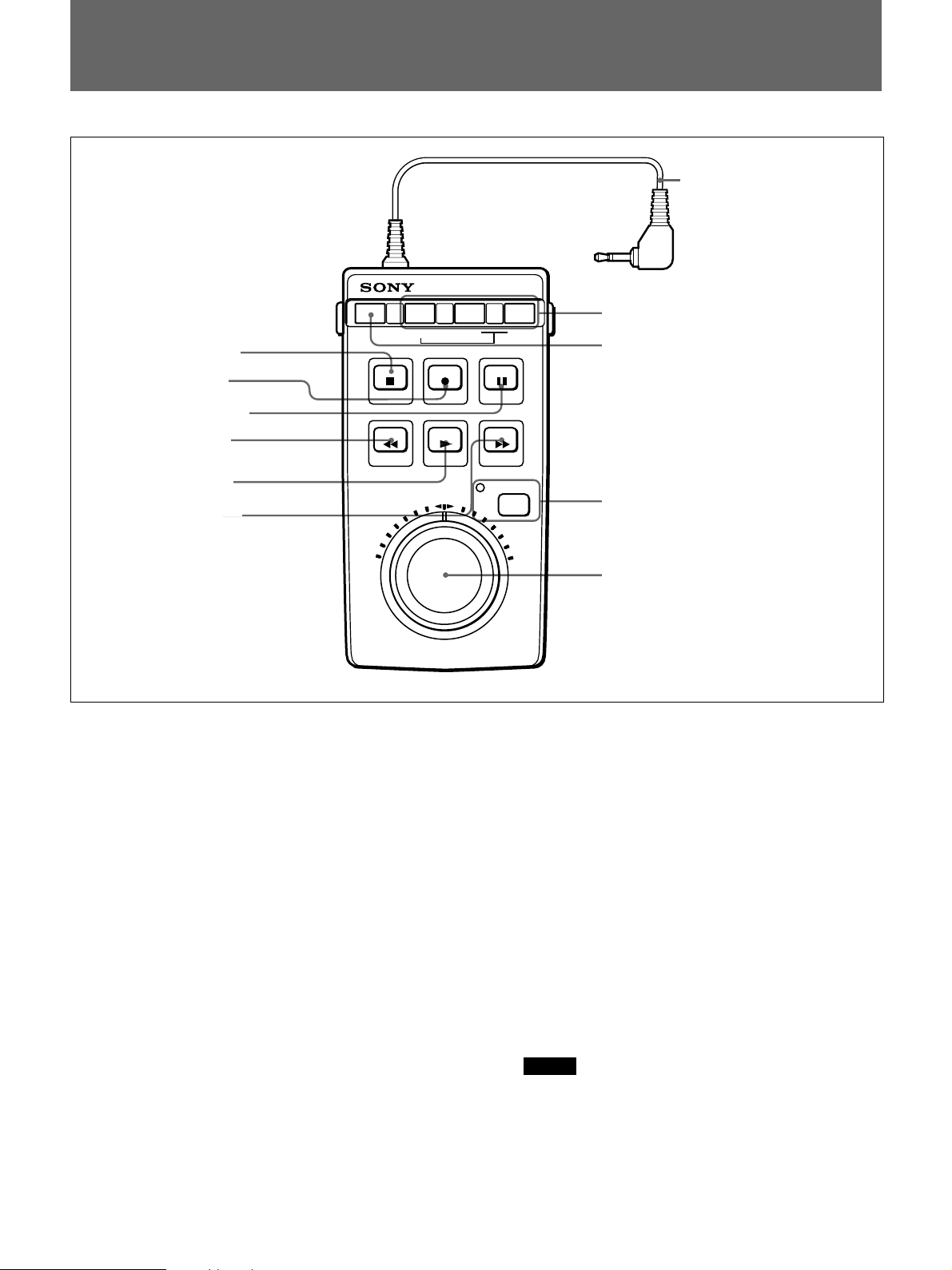
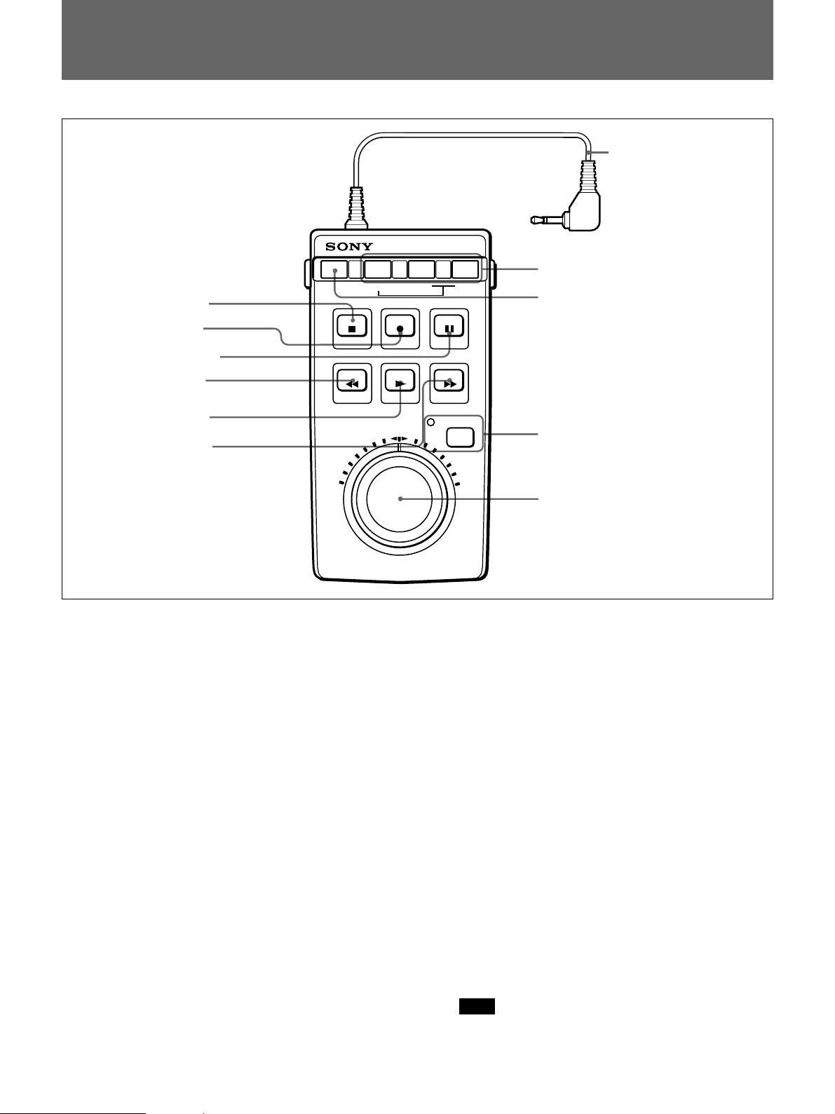
1 STOP button
2 REC button
3 PAUSE button
4 REW button
DATA CODE SEARCH MODE
STOP REC
REW
PLAY
=
!¡ Connection cable
0 SEARCH MODE buttons
=
9 DATA CODE button
PAUSE
F FWD
5 PLAY button
6 F FWD button
1 STOPpbutton
Press to stop the tape.
2 REC r (recording) button
To perform recording, press this button to put the VCR
into recording pause mode, and then press the PAUSE
P button 3.
3 PAUSE P button
Press to pause recording or playback. Press again to
cancel the pause mode.
4 REW 0 (rewind) button
When the VCR is in stop mode, press to rewind the
tape.
When the tape is being played back or rewound, press
and hold this button to rewind the tape with displaying
the playback picture.
5 PLAY ( button
Press to play the tape back.
JOG/SHUTTLE
8 JOG/SHUTTLE button/indicator
7 Search dials
6 F FWD ) (fast forward) button
When the VCR is in stop mode, press to fast forward
the tape.
When the tape is being played back or fast forwarded,
press and hold this button to fast forward the tape with
displaying the playback picture.
7 Search dials
Clockwise rotation plays the tape in the forward
direction and the counterclockwise rotation plays it in
the reverse direction.
Shuttle dial (outer): The speed of playback is
determined by the position of the dial, in the range
from –14 to +14 (for DSR-40) or –17 to +17 (for
DSR-40P) times normal speed. When the shuttle
dial is in its center position, a still image is
obtained.
Jog dial (inner): The speed of playback is
determined by the speed of turning the dial, in the
range from –2 to +2 times normal speed.
Note
The jog dial only operates when the shuttle dial is
in its center click position.
14
Page 15
8 JOG/SHUTTLE button/indicator
Press to play the tape in jog/shuttle mode. The
indicator lights and the DSR-40/40P enters jog/shuttle
mode.
Press any tape transport button to return to the normal
operating mode.
0 SEARCH MODE =or + buttons
Press these buttons to search for scenes using the index
function.
For details, see “Searching Using the Index Function” on
page 17.
9 DATA CODE button
Press this button to display the tape information on the
monitor screen.
For details, see “Displaying Tape Information” on page 20.
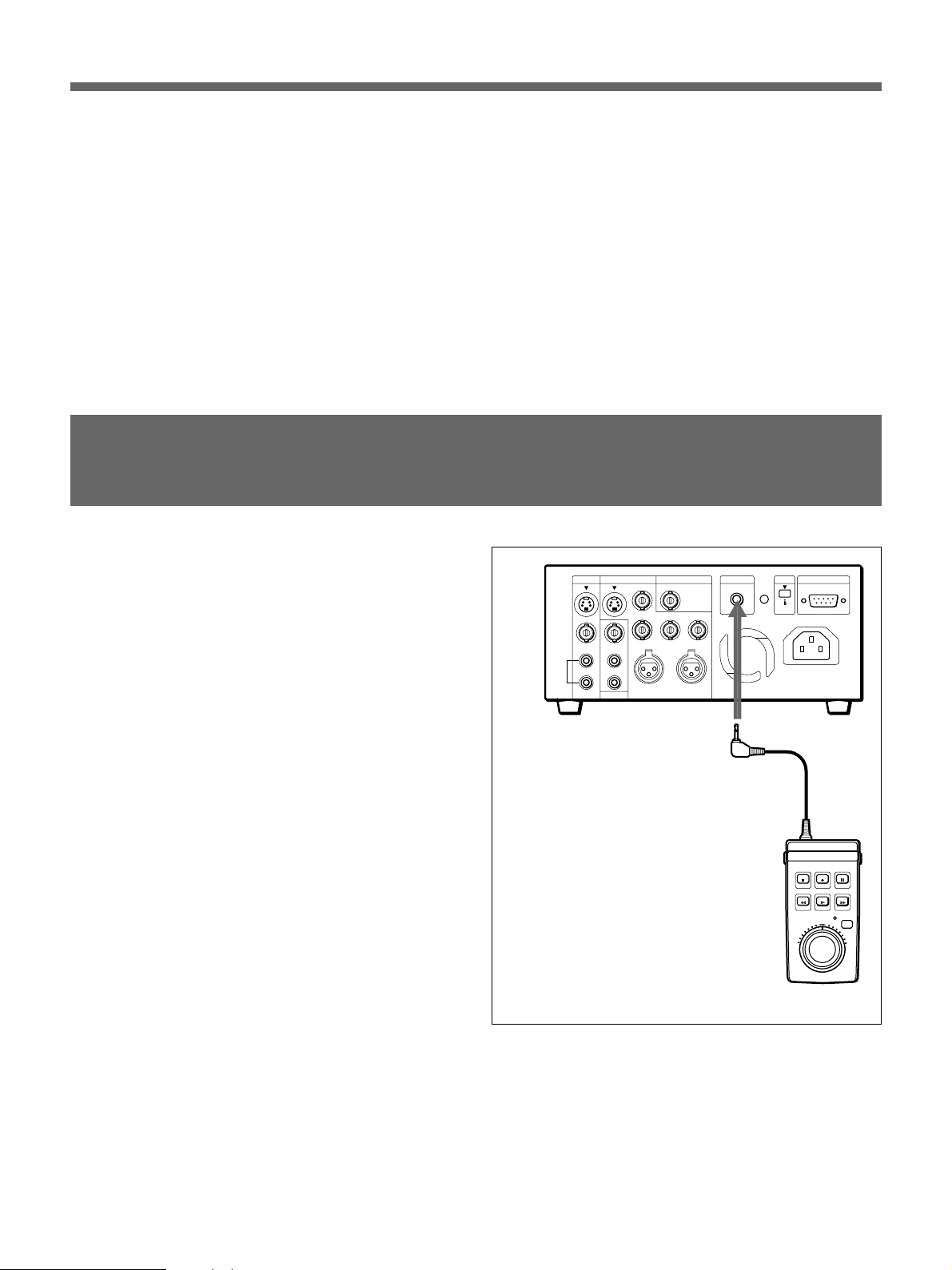
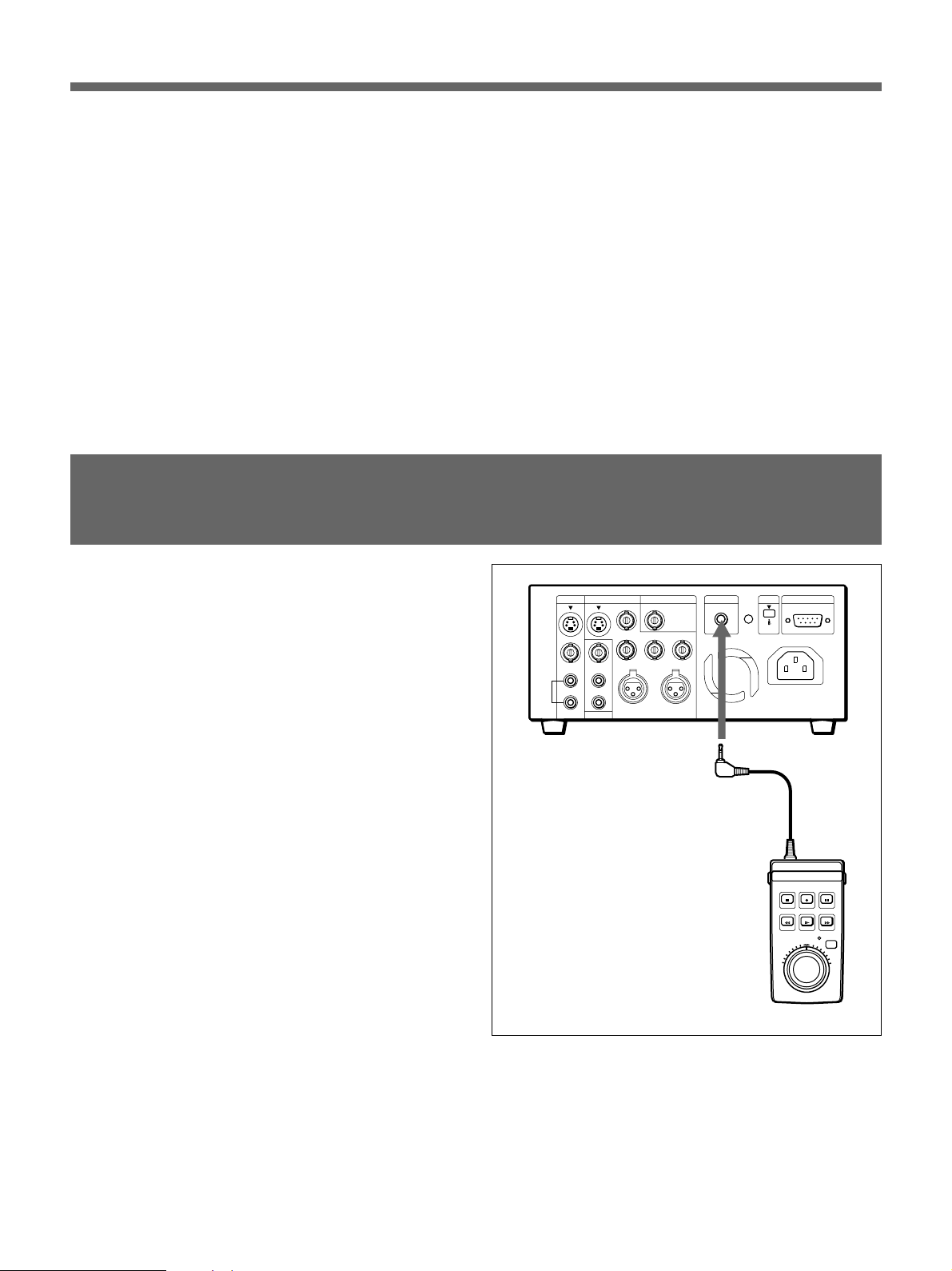
Connection
Connect this unit to the CONTROL S connector of the
DSR-40/40P.
Power is automatically supplied to this unit from the
DSR-40/40P.
!¡ Connection cable (with stereo miniplug)
Connect this to the CONTROL S connector of the
DSR-40/40P.
CONTROL S connector
DSRM-20
15
Page 16
Operation
Operation
Jog/Shuttle Search
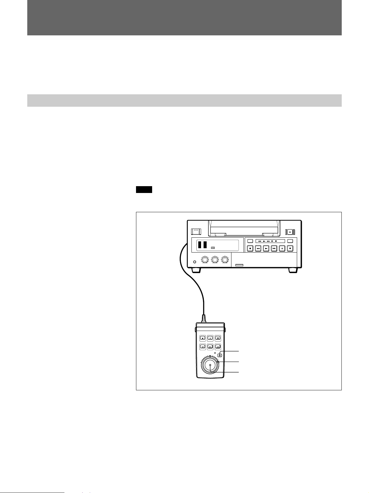
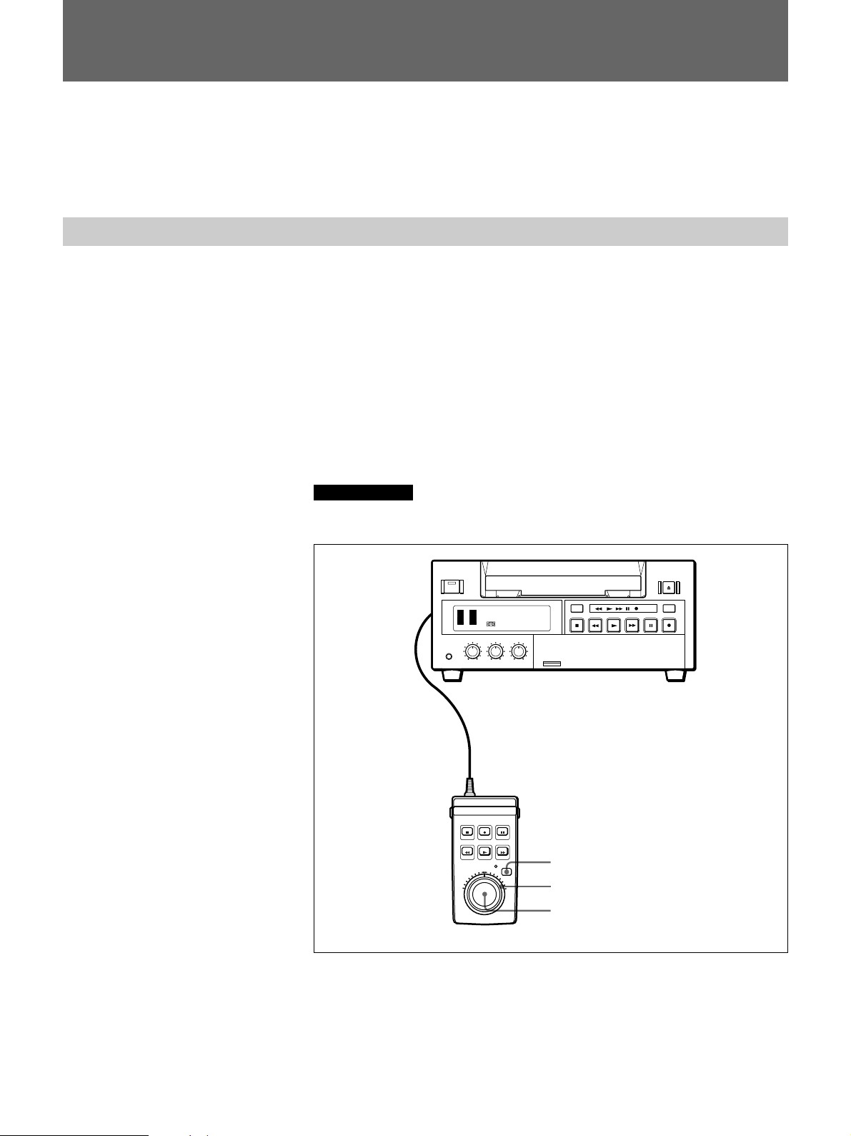
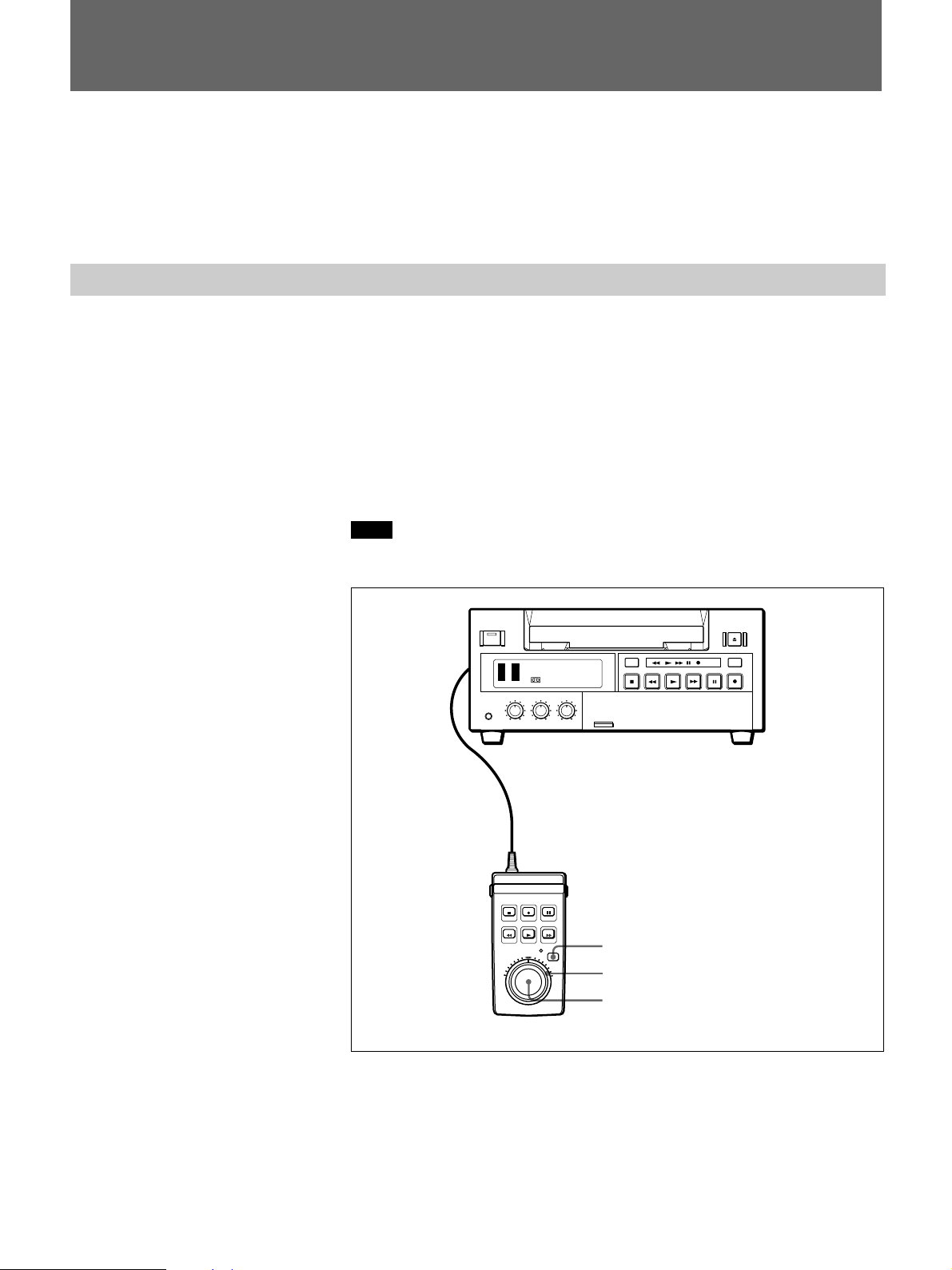
The tape transport buttons of this unit function the same as those on the
DSR-40/40P. Recording, playback, fast forward, rewind and pause can be
remotely controlled from this unit.
Using the search dials, a search operation can be performed in either jog or
shuttle mode.
Jog mode: The speed of playback is determined by the speed of turning
the jog dial, in the range from –2 to +2 times normal speed.
Shuttle mode: The speed of playback is determined by the position of
the shuttle dial, in the range from –14 to +14 (for DSR-40) or –17 to
+17 (for DSR-40P) times normal speed. When the shuttle dial is in its
center position, a still image is obtained.
Note
When operating immediately after the power is turned on, be sure to first
return the shuttle dial to its center position.
DUP
COUNTER
AUDIO
SELECT
TC
CH-1/2
CH-3/4
MONITOR
MIX
TIMER
REMOTE
REPEAT
OFF
MENU
REC
LOCAL
SET
INPUT
SELECT
COUNTER
REMAIN
CONTROL S connector
TAPE
1
2-1)
2-2)
DSRM-20
1 Press the JOG/SHUTTLE button to activate jog/shuttle mode.
The JOG/SHUTTLE indicator lights.
16
2 To search in jog mode
1) Set the shuttle dial to the center click position.
2) Turn the jog dial.
Each time you turn the jog dial by a discrete amount, this jogs the
playback one frame at a time, either forward or backward.
Page 17
To search in shuttle mode
Turn the shuttle dial.
A playback image appears at the speed according to the angle of the
dial rotation. When the dial is set at the center click position, the tape
stops and still image is obtained.
To exit from jog/shuttle mode
Press any tape transport button.
The JOG/SHUTTLE indicator goes off, and the recorder or player changes
to the operation corresponding to the pressed button.
Searching Using the Index Function
Three kinds of search are available using this unit.
– Searching for the beginnings of recordings: Index search
– Searching for a point on the tape where the recorded date changes:
Date search
– Searching for scenes recorded in the photo mode with a digital
camcorder: Photo search
When using a cassette with cassette memory
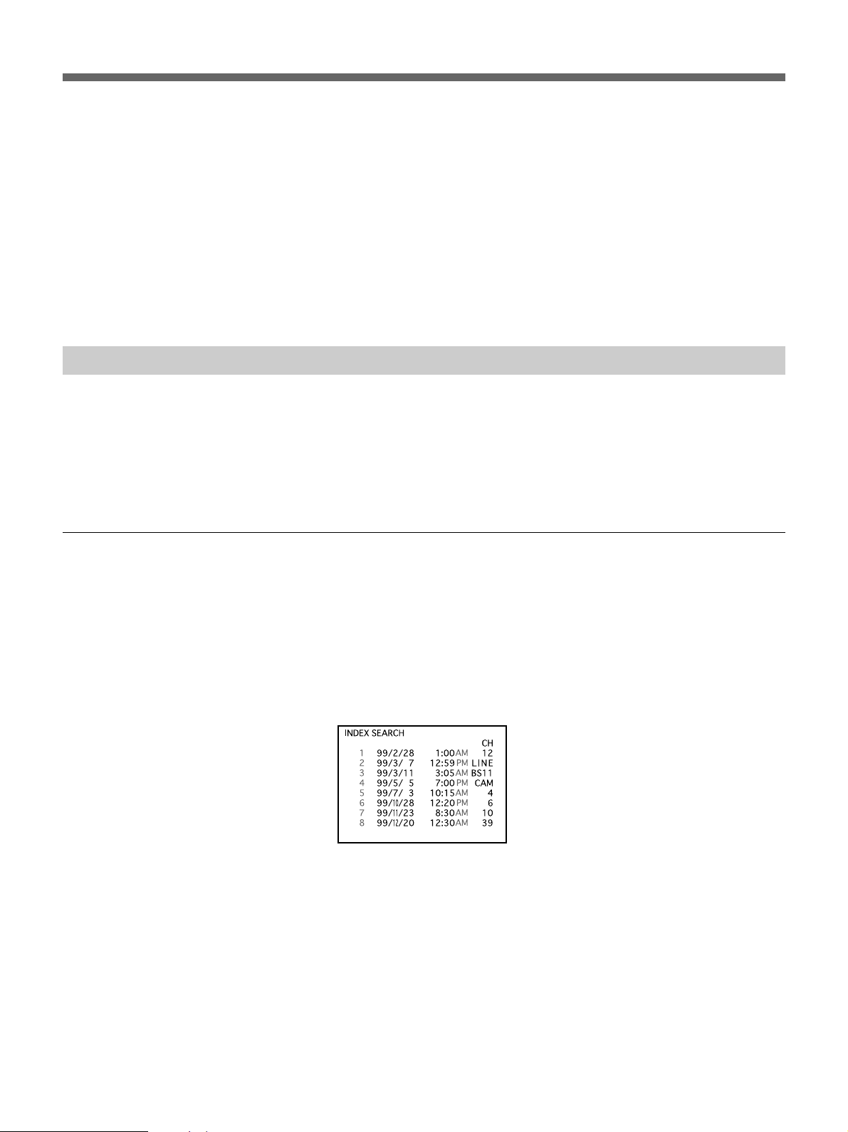
If the cassette has a cassette memory, the recordings are listed in the
chronologically in the order they were made. You can search using this
chronological list.
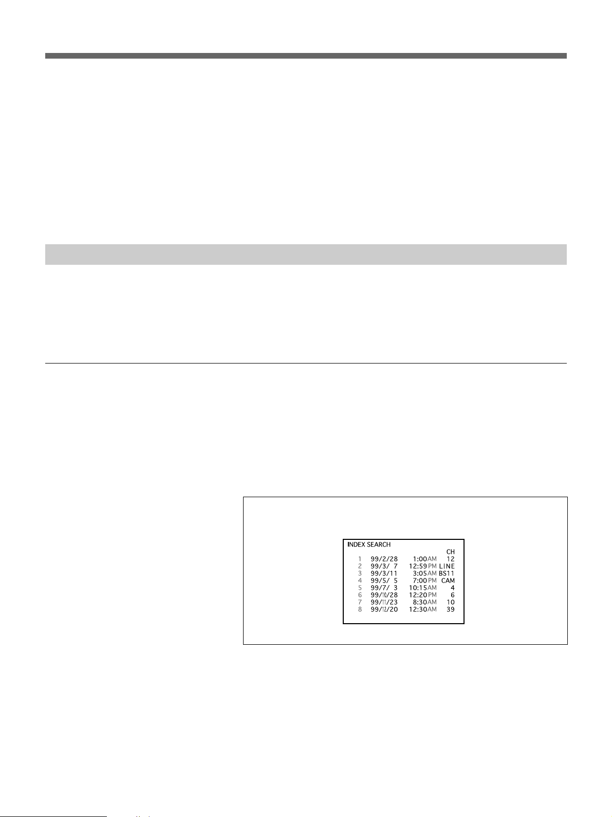
1 Press SEARCH MODE to select the search type: INDEX, DATE or
PHOTO SEARCH.
The chronological list appears on the monitor screen.
µ
When selecting INDEX SEARCH
2 Press = or + to select a recording.
The VCR starts searching and when it locates the recording, begins
playback. During Photo search, the VCR pauses.
17
Page 18

Operation
When using a cassette without cassette memory
When you use a cassette without cassette memory, the VCR searches in
the order of the actual positions of the recordings, regardless of the setting
of CASSETTE MEMORY SEARCH in the DSR-40/40P’s menu.
For more information about menu operations, refer to the operating instructions
for the DSR-40/40P.
1 Press SEARCH MODE to select the search type.
INDEX 0
SEARCH
When selecting INDEX SEARCH
How signals are recorded
2 Press =or + repeatedly to locate the recording you want.
The VCR starts searching backwards or forwards until the index
number comes to zero, then plays back the recording. During Photo
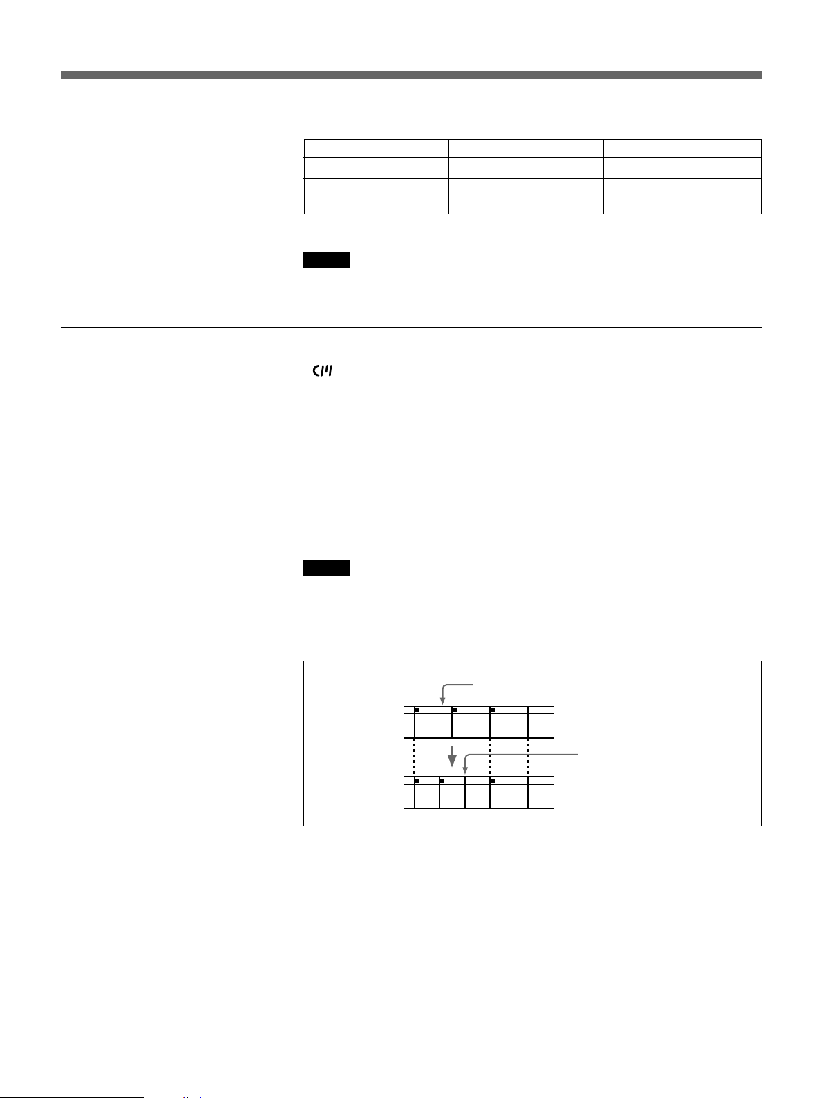
search, the VCR pauses.
The VCR marks the tape when REC is pressed.
There are three different signals for each search method. The type of signal
recorded and where it is recorded (on the tape or in the cassette memory)
depends on the video equipment used for recording. Please note that if the
signals for certain search type are not recorded, you cannot do that type of
search.
When you record with a Sony digital camcorder
(DSR-200/200P, DSR-200A/200AP or DSR-PD100/PD100P)
Signals for In cassette memory On tape
Index search
Date search Yes Yes
Photo search Yes Yes
a)
No No
18
a) The signals for Index search are recorded when you start recording in stop
mode.
Page 19
About the cassette memory
When you record on the DSR-40/40P
Signals for In cassette memory On tape
Index search
Date search No Yes
Photo search No No
a) The signals for Index search are recorded when you start recording in stop
mode.
Note
a)
Yes Yes
When recording on the DSR-40/40P, signals for index search do not have
information on a day of the week.
•If you use a cassette with mark, the cassette memory stores up to 135
index signals. (The number changes depending on the data size
combination of index, date, and photo data stored on a tape.) The DSR40/40P is capable of storing and retrieving up to 16 kbits of cassette
memory.
•To locate recordings whose signals are disabled to be stored in the
cassette memory, or to locate recordings in order of their position on the
tape, set CASSETTE MEMORY SEARCH in the menu to OFF. You can
use the same procedure to search for a recording on a cassette without
cassette memory.
For more information about menu operations, refer to the operating instructions
for the DSR-40/40P.
Notes
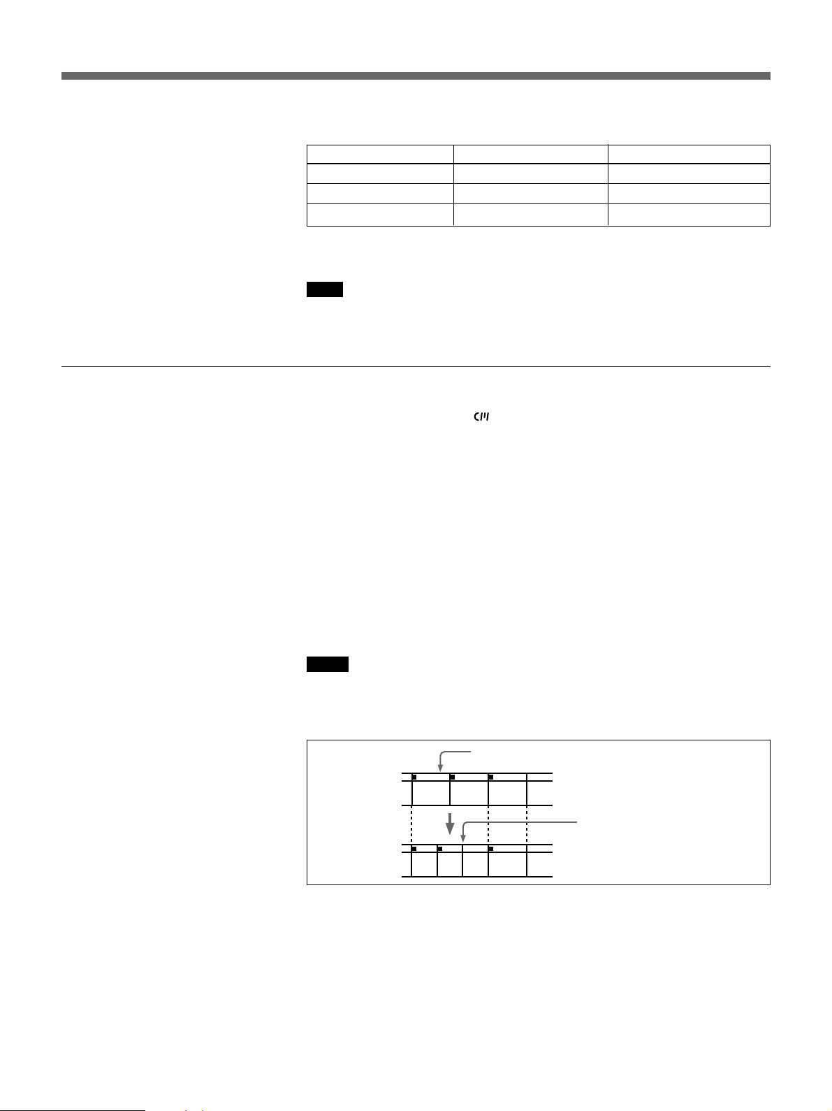
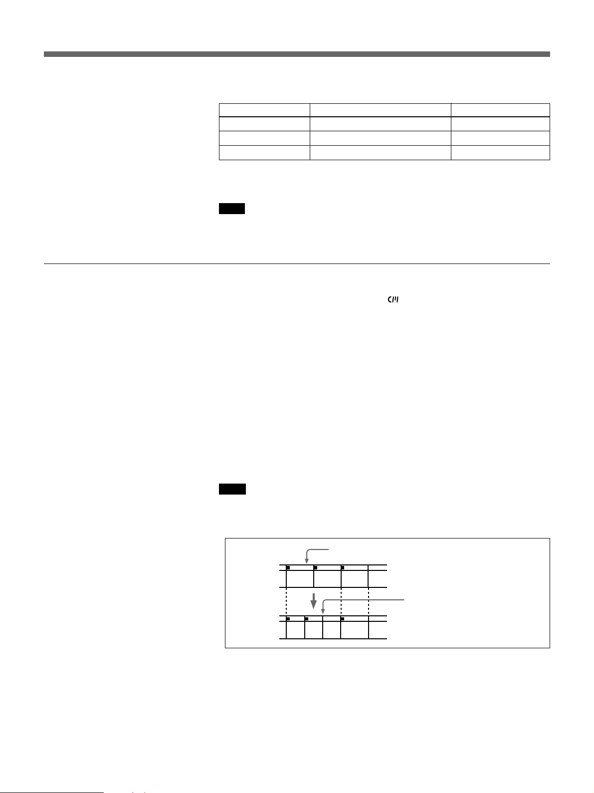
•Each program is indexed at its beginning. If you record another program
over the beginning of the first program, you will not be able to locate the
original program.
Index signal
ABC
If D is recorded
over the beginning of B...
B cannot be searched
ABCD
•You cannot add indexes after recording.
To add indexes only for Auto Repeat, start recording from the point you
want to start indexing.
•You cannot erase indexes after recording.
To delete indexes for Auto Repeat, set INDEX WRITE in the menu to
OFF. Then record over the index signal you want to erase.
•Searching may not be done correctly if the signals were not recorded on a
Sony-brand digital video equipment.
For more information about menu operations, refer to the operating instructions
for the DSR-40/40P.
19
Page 20
Operation
Displaying T ape Information
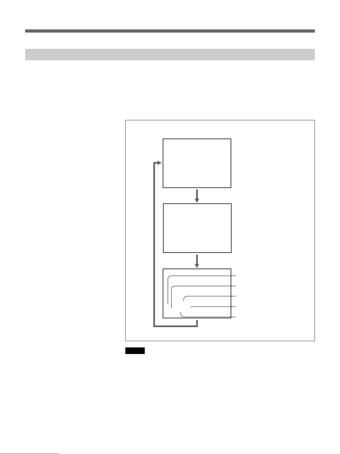
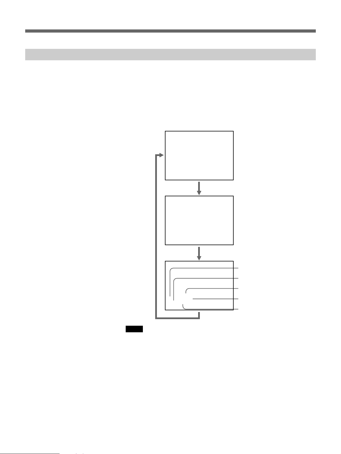
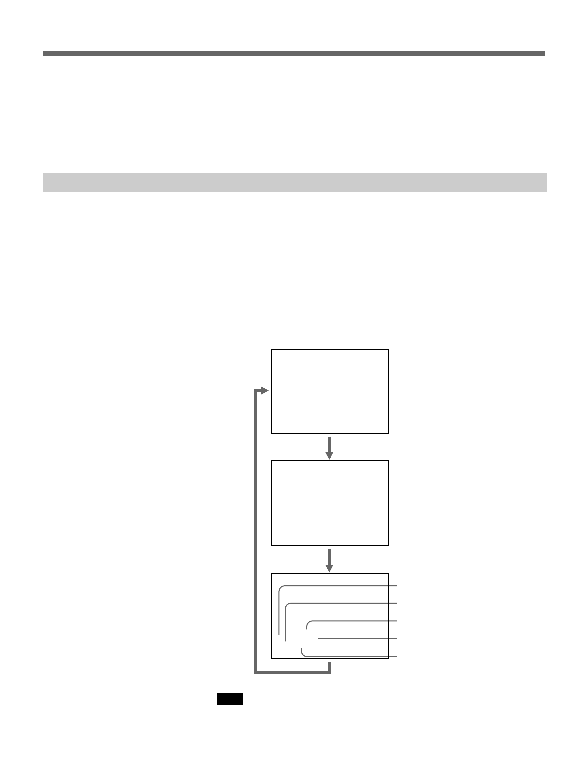
If you record on a tape using a Sony digital camcorder DSR-200/200A/
PD100 (or DSR-200P/200AP/PD100P), camcorder data (the shutter speed,
program AE mode, white balance, iris and gain) can be recorded on the
tape. You can check this data during playback on the DSR-40/40P.
Press DATA CODE during playback.
Each time you press DATA CODE, the display changes as follows.
Data display off
Recording
date and time
1999 / 12 / 25
12:59 AM LINE
Sony camcorder
settings
Shutter speed
Iris
White balance
Notes
AWB
60 MANUAL
F 1.6 0 dB
Program AE mode
Gain
•When the information was not recorded, “- - -” appears instead.
•The camcorder data displayed on the monitor screen by the DSR-40/40P
are partially different from those shown by the digital camcorder.
20
Page 21

Specifications
Remote control Stereo mini-plug (with attached cable, length 3 m (10
ft))
Power requirements
5 V DC (supplied from the DSR-40/40P)
Power consumption
50 mW
Storage temperature
–20°C to +60°C (–4°F to +140°F)
Operating temperature
5°C to 40°C (41°F to 104°F)
Dimensions (w/h/d)
90 × 46 × 182 mm (3
not including the interface cable
Mass Approx. 360 g (12 oz)
Supplied accessories
Operating instructions (1)
Design and specifications are subject to change without notice.
5
/8 × 113/16 × 71/4 inches)
21
Page 22

Pour les clients européens
Ce produit portant la marque CE est conforme à la Directive
sur la compatibilité électromagnétique (EMC) (89/336/CEE)
émise par la Commission de la Communauté européenne.
La conformité à cette directive implique la conformité aux
normes européennes suivantes:
• EN55103-1: Interférences électromagnétiques (émission)
• EN55103-2: Sensibilité électromagnétique (immunité)
Ce produit est prévu pour être utilisé dans les
environnements électromagnétiques suivants:
E1 (résidentiel), E2 (commercial et industrie légère), E3
(urbain extérieur) et E4 (environnement EMC contrôlé ex.
studio de télévision).
22
Page 23

Français
Table des matières
Généralités
Généralités.......................................................................23
Nomenclature. .................................................................24
Connexions......................................................................25
Exploitation......................................................................26
Recherche par impulsion/navette ...................................... 26
Recherche à l’aide de la fonction d’index......................... 27
Affichage des informations sur la bande........................... 30
Spécifications..................................................................31
La télécommande DSRM-20 est conçue pour commander un
magnétoscope DSR-40/40P. Son utilisation avec le DSR-40/40P procure
les fonctions suivantes à ce dernier.
Recherche par impulsion/navette
La bague de navette permet de visionner les images à une vitesse de –14 à
+14 (pour le DSR-40) ou –17 à +17 (pour le DSR-40P) fois la vitesse
normale, ainsi qu’en mode d’image fixe, tandis que la bague d’impulsion
permet de les visionner de –2 à +2 fois la vitesse normale, ainsi qu’en
mode d’image fixe.
Recherche d’index
Des points souhaités peuvent rapidement être trouvés en utilisant les
signaux d’index ou les informations de date et de mode photo. Les signaux
d’index sont enregistrés sur la bande et les informations de date et de mode
photo dans la mémoire cassette (si la cassette en est pourvue).
Affichage des informations de la cassette
Les informations concernant le camescope peuvent être affichées pendant
la lecture si la cassette a été utilisée pour la prise de vue sur le camescope
DSR-200/200A/PD1/PD100 (ou DSR-200P/200AP/PD1P/PD100P).
FR
Français
23
Page 24
Nomenclature
Nomenclature
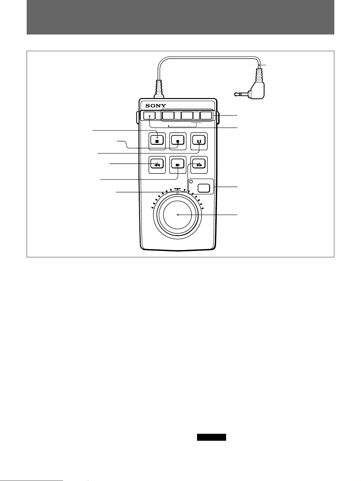
1 Touche d’arrêt
2 Touche d’enregistrement
3 Touche de pause
4 Touche de rebobinage
DATA CODE SEARCH MODE
STOP REC
REW
PLAY
=
!¡ Câble de raccordement
0 Touches de mode de recherche
=
9 Touche de code de données
PAUSE
F FWD
5 Touche de lecture
6 Touche d’avance rapide
1 Touche d’arrêt (STOP p)
Appuyer pour arrêter la bande.
2 Touche d’enregistrement (REC r)
Pour enregistrer, appuyer sur la touche VCR en mode
pause d’enregistrement, puis sur la touche PAUSE P
3.
3 Touche de pause (PAUSE P)
Appuyer pour faire une pause d’enregistrement ou de
lecture.
Appuyer à nouveau pour annuler le mode de pause.
4 Touche de rebobinage (REW 0)
Quand le magnétoscope est en mode d’arrêt, presser
pour rebobiner la bande.
A la lecture ou au rebobinage de la bande, maintenir
cette touche pressée pour rebobiner en affichant
l’image lue.
5 Touche de lecture (PLAY ()
Appuyer pour lire la bande.
JOG/SHUTTLE
8 Touche/témoin de lecture par
impulsion/navette
7 Bagues de recherche
6 Touche d’avance rapide (F FWD ))
Quand le magnétoscope est en mode d’arrêt, presser
pour faire avancer rapidement la bande.
A la lecture ou à l’avance rapide, maintenir cette
touche pressée pour faire avancer rapidement la bande
en affichant l’image lue.
7 Bagues de recherche
Les tourner dans le sens horaire pour lire la bande en
marche avant, et dans le sens contraire pour la lire en
marche arrière.
Bague de navette (extérieure): La vitesse de lecture
est déterminée par la position de la bague, sur la
plage de –14 à +14 (pour le DSR-40) ou –17 à +17
(pour le DSR-40P) fois la vitesse normale. Une
image fixe s’affiche quand la bague de navette est
en position centrale.
Bague d’impulsion (intérieure): La vitesse de lecture
est déterminée par la vitesse de rotation de la
bague, sur la plage de –2 à +2 fois la vitesse
normale.
Remarque
La bague d’impulsion est opérante quand la bague
de navette est à la position centrale à déclic.
24
Page 25
8 Touche/témoin de lecture par impulsion/
navette (JOG/SHUTTLE)
Appuyer pour lire la bande en mode d’impulsion ou de
navette. Le témoin s’allume et le DSR-40/40P passe en
mode d’impulsion ou de navette.
Appuyer sur une touche de transport de bande pour
revenir en mode de fonctionnement normal.
0 Touches de mode de recherche (SEARCH
MODE =ou +)
Appuyer sur ces touches pour rechercher des scènes à
l’aide de la fonction d’index.
Pour plus de détails, se reporter à “Recherche à l’aide de la
fonction d’index” à la page 27.
9 Touche de code de données (DATA CODE)
Appuyer sur cette touche pour afficher les
informations de la cassette sur l’écran du moniteur.
Pour plus de détails, se reporter à “Affichage des
informations sur la bande” à la page 30.
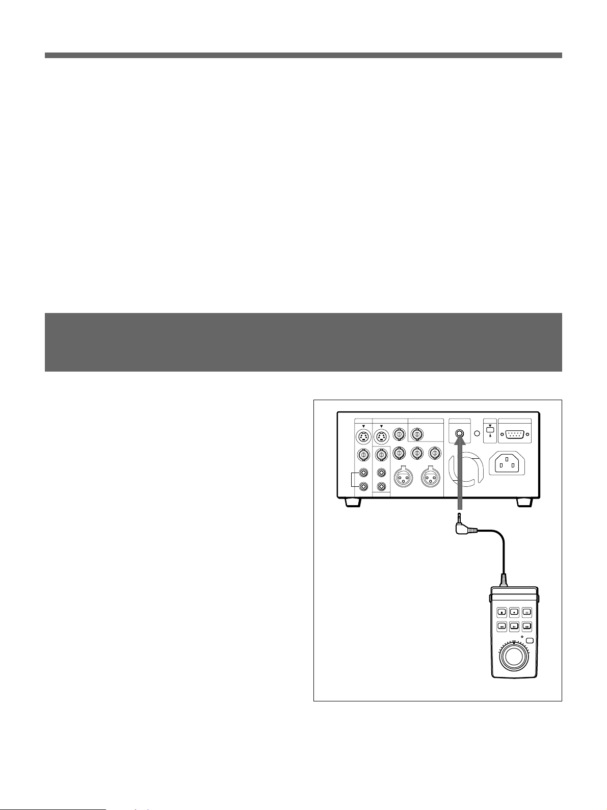
Connexions
Raccorder cet appareil au connecteur CONTROL S du
DSR-40/40P.
Cet appareil est automatiquement alimenté depuis le
DSR-40/40P.
!¡ Câble de raccordement (à minifiche stéréo)
Le raccorder au connecteur CONTROL S du DSR-40/
40P.
Connecteur CONTROL S
DSRM-20
25
Page 26
Exploitation
Exploitation
Les touches de transport de bande de cet appareil fonctionnent comme
celles du DSR-40/40P. L’enregistrement, la lecture, l’avance rapide, le
rebobinage et la pause peuvent être commandés à distance depuis cette
télécommande.
Recherche par impulsion/navette
Une opération de recherche peut être effectuée en mode d’impulsion ou de
navette avec les bagues de recherche.
Mode d’impulsion: la vitesse de lecture est déterminée par la vitesse de
rotation de la bague d’impulsion, sur la plage de –2 à +2 fois la vitesse
normale.
Mode de navette: la vitesse de lecture est déterminée par la position de
la bague de navette, sur la plage de –14 à +14 (pour le DSR-40) ou –
17 à +17 (pour le DSR-40P) fois la vitesse normale. Une image fixe
est obtenue quand la bague de navette est en position centrale.
Remarque
Pour une opération immédiatement après la mise sous tension, toujours
ramener la bague de navette en position centrale.
DUP
COUNTER
AUDIO
INPUT
SELECT
COUNTER
REMAIN
TIMER
SELECT
MONITOR
TC
TAPE
REMOTE
CH-1/2
REPEAT
MIX
OFF
CH-3/4
MENU
REC
LOCAL
SET
Connecteur CONTROL S
1
2-1)
2-2)
DSRM-20
26
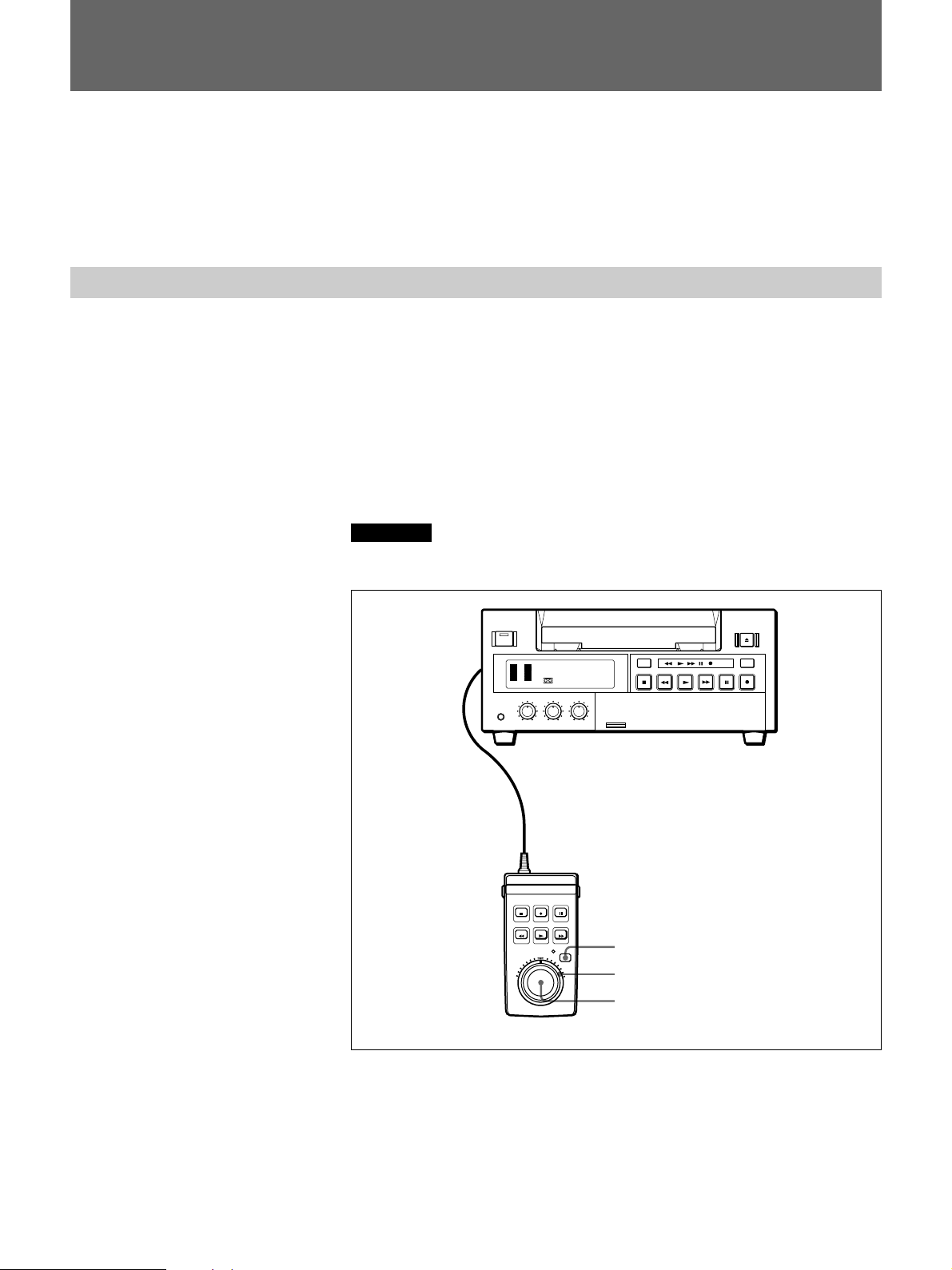
1 Appuyer sur la touche JOG/SHUTTLE pour activer le mode
d’impulsion/navette.
Le témoin JOG/SHUTTLE s’allumera.
Page 27

2 Recherche en mode d’impulsion
1) Mettre la bague de navette à la position à déclic.
2) Tourner la bague d’impulsion.
A chaque légère rotation de la bague d’impulsion, la bande défile
cadre par cadre, en avant ou en arrière.
Recherche en mode de navette
Tourner la bague de navette.
L’image lue apparaît à la vitesse correspondant à l’angle de rotation de
la bague. Quand la bague est sur la position centrale à déclic, la bande
s’arrête et une image fixe est obtenue.
Pour quitter le mode d’impulsion/navette
Appuyer sur une touche de transport de bande.
Le témoin JOG/SHUTTLE s’éteindra, et l’enregistreur ou le lecteur
passera au mode d’exploitation correspondant à la touche pressée.
Recherche à l’aide de la fonction d’index
Trois sortes de recherche sont disponibles avec cette télécommande.
– Recherche du début des enregistrements: recherche d’index
– Recherche d’un endroit sur une cassette où la date d’enregistrement
change: recherche par date
– Recherche de scènes enregistrées en mode photo au moyen d’un
camescope numérique: recherche photo
Avec une cassette avec mémoire cassette
Si la cassette dispose d’une mémoire cassette, les enregistrements sont
listés chronologiquement dans l’ordre de leur création. Vous pouvez
effectuer la recherche à l’aide de la liste chronologique.
1 Appuyer sur SEARCH MODE pour sélectionner le type de recherche:
INDEX, DATE ou PHOTO SEARCH.
La liste chronologique apparaît sur l’écran du moniteur.
En sélectionnant INDEX SEARCH
2 Appuyer sur = ou + pour sélectionner un enregistrement.
Le magnétoscope se met à chercher et lorsqu’il localise
l’enregistrement, il entame la lecture. Lors de la recherche photo, le
magnétoscope passe en mode de pause.
µ
27
Page 28

Exploitation
Avec une cassette sans mémoire cassette
Dans le cas d’une cassette sans mémoire cassette, le magnétoscope
effectue la recherche dans l’ordre des positions réelles des
enregistrements, quel que soit le réglage de CASSETTE MEMORY
SEARCH dans le menu du DSR-40/40P.
Pour plus d’informations sur les opérations de menu, voir le mode d’emploi du
DSR-40/40P.
1 Appuyer sur SEARCH MODE pour sélectionner le type de recherche.
INDEX 0
SEARCH
En sélectionnant INDEX SEARCH
2 Appuyer plusieurs fois sur = ou + pour localiser
l’enregistrement souhaité.
Le magnétoscope commence la recherche vers l’arrière ou vers l’avant
jusqu’au numéro d’index zéro, puis la lecture de l’enregistrement
commence. En cours de recherche photo, le magnétoscope passe en
mode de pause.
Comment les signaux sont-ils enregistrés?
Le magnétoscope fait une marque à la pression de la touche REC.
Il existe trois différents signaux pour chaque méthode de recherche. Le
type de signal enregistré et l’endroit où il est enregistré (sur la bande ou
dans la mémoire cassette) dépendent de l’appareil vidéo utilisé pour
l’enregistrement. Noter que si les signaux ne sont pas enregistrés pour un
certain type de recherche, ce type de recherche est impossible.
Enregistrement avec un camescope numérique Sony (DSR200/200P, DSR-200A/200AP ou DSR-PD100/PD100P)
Signaux pour Dans la mémoire cassette Sur la bande
Recherche d’index
Recherche par date Oui Oui
Recherche photo Oui Oui
a) Les signaux pour la recherche d’index sont enregistrés au démarrage de
l’enregistrement en mode d’arrêt.
a)
Non Non
28
Page 29
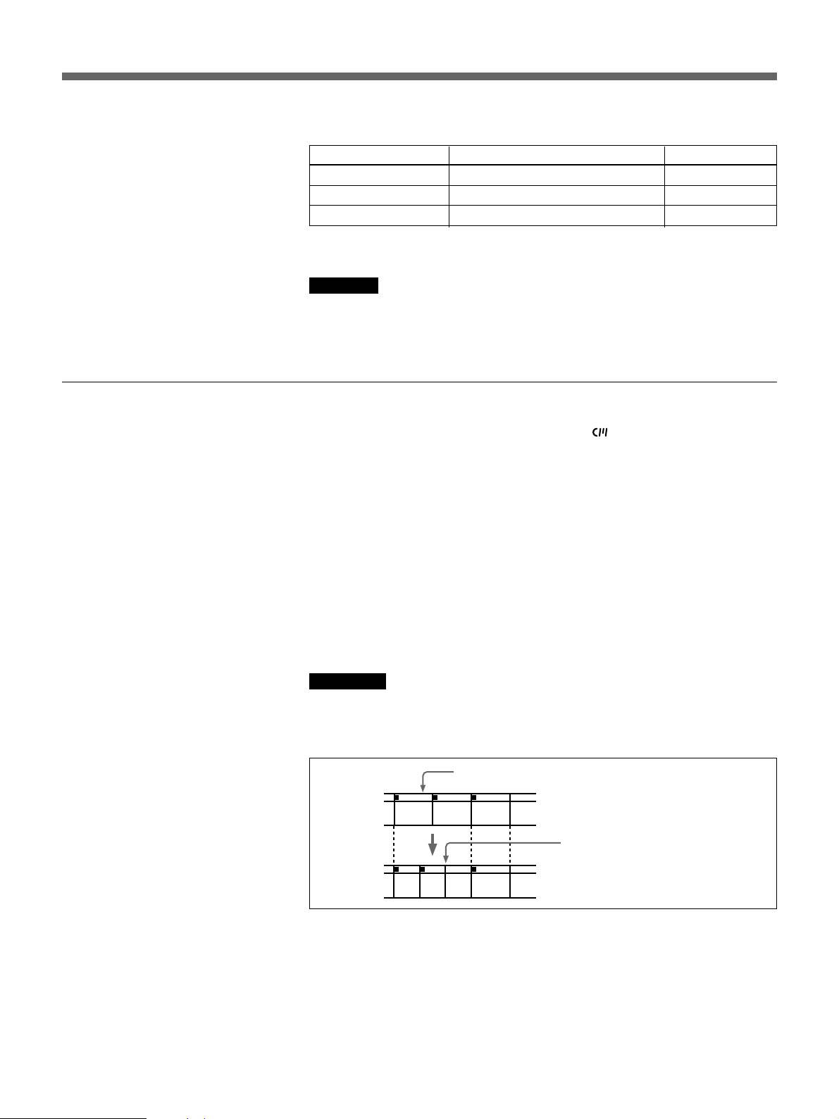
A l’enregistrement sur le DSR-40/40P
Signaux pour Dans la mémoire de cassette Sur la bande
Recherche d’index
Recherche de date Non Oui
Recherche photo Non Non
a) Les signaux pour la recherche d’index sont enregistrés au démarrage de
Remarque
Lors d’un enregistrement sur le DSR-40/40P, les signaux pour la recherche
d’index ne contiennent pas d’informations concernant le jour de la
semaine.
A propos de la mémoire cassette
•Si vous utilisez une cassette avec la marque , la mémoire cassette
•Pour localiser les enregistrements dont les signaux de stockage dans la
a)
Oui Oui
l’enregistrement en mode d’arrêt.
mémorise jusqu’à 135 signaux d’index. (Le nombre varie en fonction de
la taille des données, de la combinaison de données d’index, de date et
photo sauvegardées sur la bande.) Le DSR-40/40P est capable de
conserver et d’extraire jusqu’à 16 kbits de données de mémoire cassette.
mémoire cassette sont invalidés, ou des enregistrements dans l’ordre de
leur position sur la bande, mettre CASSETTE MEMORY SEARCH dans
le menu sur OFF. La même procédure est utilisable pour rechercher un
enregistrement sur une cassette sans mémoire cassette.
Pour plus d’informations sur les opérations de menu, voir le mode d’emploi du
DSR-40/40P.
Remarques
•Chaque programme est indexé à son début. Si un autre programme est
enregistré sur le début du premier programme, la localisation du
programme d’origine sera impossible.
Signal d’index
ABC
Si D est enregistré sur le
début de B...
B ne peut pas être recherché
ABCD
•Des index ne peuvent pas être ajoutés après l’enregistrement.
Pour ajouter des index uniquement pour la fonction Auto Repeat,
commencer l’enregistrement à l’endroit où l’indexation doit commencer.
•Des index ne peuvent pas être supprimés après l’enregistrement.
Pour supprimer des index pour Auto Repeat, mettre INDEX WRITE dans
le menu sur OFF. Ensuite, enregistrer sur le signal d’index à effacer.
29
Page 30
Exploitation
•Il est possible que la recherche ne s’effectue pas correctement si les
signaux n’ont pas été enregistrés sur un appareil vidéo numérique de
marque Sony.
Pour plus d’informations sur les opérations de menu, voir le mode d’emploi du
DSR-40/40P.
Affichage des informations sur la bande
Si une cassette est enregistrée à l’aide d’un camescope numérique Sony
DSR-200/200A/PD100 (ou DSR-200P/200AP/PD100P), les données du
camescope (la vitesse d’obturateur, le mode programmé AE, la balance du
blanc, le diaphragme et le gain) peuvent être enregistrées sur la bande. Ces
données peuvent être vérifées en cours de lecture sur le DSR-40/40P.
Appuyer sur DATA CODE en cours de lecture.
A chaque pression de DATA CODE, l’affichage change comme suit:
Affichage des données désactivé
30
Date et heure
d’enregistrement
1999 / 12 / 25
12:59 AM LINE
Réglages du
camescope Sony
Vitesse d’obturateur
Diaphragme
Balance du blanc
Remarques
AWB
60 MANUAL
F 1.6 0 dB
Mode programmé AE
Gain
•Lorsque les informations n’ont pas été enregistrées, “- - -” apparaît à la
place.
•Les données du camescope affichées sur l’écran du moniteur par le DSR-
40/40P sont partiellement différentes de celles affichées par le camescope
numérique.
Page 31

Spécifications
Télécommande Minifiche stéréo (avec câble, longueur 3 m (10 pieds))
Alimentation Courant continu de 5 V (fourni depuis le DSR-40/40P)
Consommation 50 mW
Température de stockage
–20˚C à +60°C (–4˚F à +140°F)
Température de fonctionnement
5˚C à 40°C (41˚F à 104°F)
Dimensions (l/h/p)
90 × 46 × 182 mm (3
Poids Approx. 360 g (12 onces)
Accessoire fourni
Mode d’emploi (1)
La conception et les spécifications sont sujettes à modification sans
préavis.
5
/8 × 113/16 × 71/4 pouces)
31
Page 32

Für Kunden in Europa
Dieses Produkt besitzt die CE-Kennzeichnung und erfüllt die
EMV-Direktive (89/336/EEC) der EG-Kommission.
Die Erfüllung dieser Direktive bedeutet Konformität für die
folgenden Europäischen Normen:
• EN55103-1: Elektromagnetische Interferenz (Emission)
• EN55103-2: Elektromagnetische Empfindlichkeit
(Immunität)
Dieses Produkt ist für den Einsatz unter folgenden
elektromagnetischen Bedingungen ausgelegt:
E1 (Wohnbereich), E2 (kommerzieller und in beschränktem
Maße industrieller Bereich), E3 (Stadtbereich im Freien) und
E4 (kontrollierter EMV-Bereich, z.B. Fernsehstudio).
32
Page 33

Deutsch
Inhaltsverzeichnis
Allgemeines
Allgemeines .....................................................................33
Lage und Funktion der Teile...........................................34
Anschluß..........................................................................35
Bedienung........................................................................36
Jog/Shuttle-Suchlauf ......................................................... 36
Suchen mit der Indexfunktion ........................................... 37
Anzeigen von Bandinformationen..................................... 41
Technische Daten............................................................42
Die Fernsteuereinheit DSRM-20 dient zur Steuerung des Videorecorders
DSR-40P und ermöglicht die folgenden Zusatzfunktionen.
Jog/Shuttle-Funktion
Mit dem Shuttle-Ring läßt sich das Band mit –17- bis +17facher
Normalgeschwindigkeit abspielen sowie als Standbild wiedergeben. Mit
der Jog-Scheibe läßt sich das Band mit –2- bis +2facher
Normalgeschwindigkeit abspielen sowie als Standbild wiedergeben.
Indexsuchlauf
Anhand von Indexsignalen oder Zeit- und Fotomodus-Informationen
lassen sich gewünschte Bandstellen bequem und rasch lokalisieren. Die
Indexsignale werden auf Band geschrieben, während die Zeit- und
Fotomodus-Informationen im Kassettenspeicher (sofern vorhanden)
abgelegt werden.
Bandinformations-Anzeige
Während der Wiedergabe können Informationen über den Camcorder
angezeigt werden, wenn das Band mit einem DSR-200P/200AP/PD1P/
PD100P Camcorder aufgezeichnet wurde.
DE
Deutsch
33
Page 34
Lage und Funktion der Teile
Lage und Funktion der Teile
=
PLAY
1 STOP-Taste
2 REC-Taste
3 PAUSE-Taste
4 REW-Taste
DATA CODE SEARCH MODE
STOP REC
REW
!¡ Verbindungskabel
0 Tasten SEARCH MODE
=
9 Taste DATA CODE
PAUSE
F FWD
5 PLAY-Taste
6 F FWD-Taste
1 STOP p-Taste
Zum Stoppen des Bandlaufs drücken.
2 REC r-Taste
Drücken, um den Videorecorder auf Aufnahmepause
zu schalten. Dann zum Starten der Aufnahme die
PAUSE P-Taste 3 drücken.
3 PAUSE P-Taste
Drücken, um die Aufnahme oder Wiedergabe
vorübergehend anzuhalten. Erneut drücken, um sie
fortzusetzen.
4 REW 0-Taste
Bei gestopptem Band drücken, um das Band
zurückzuspulen.
Bei Gedrückthalten dieser Taste während des
Spulvorgangs erfolgt schneller Bildsuchlauf in
Rückwärtsrichtung.
5 PLAY (-Taste
Zur Bandwiedergabe drücken.
JOG/SHUTTLE
8 JOG/SHUTTLE-Taste und
Anzeige
7 Suchlaufknopf
6 F FWD )-Taste
Bei gestopptem Band drücken, um das Band
vorzuspulen.
Bei Gedrückthalten dieser Taste während des
Spulvorgangs erfolgt schneller Bildsuchlauf in
Vorwärtsrichtung.
7 Suchlaufknopf
Für Wiedergabe in Vorlaufrichtung im Uhrzeigersinn
drehen, für Wiedergabe in Rücklaufrichtung im
Gegenuhrzeigersinn drehen.
Shuttle-Ring (außen):
Die Wiedergabegeschwindigkeit wird von der
Drehposition des Shutttle-Rings innerhalb eines
Bereichs von –17- bis +17facher
Normalgeschwindigkeit bestimmt. In Mittelstellung
wird ein Standbild ausgegeben.
Jog-Scheibe (innen): Die Wiedergabegeschwindigkeit
wird innerhalb eines Bereichs von –2- bis +2facher
Normalgeschwindigkeit durch die Geschwindigkeit
bestimmt, mit der die Scheibe gedreht wird.
34
Page 35
Zur Beachtung
Die Jog-Scheibe ist nur wirksam, wenn sich der
Shuttle-Ring in seiner mittleren Raststellung
befindet.
8 JOG/SHUTTLE-Taste und Anzeige
Drücken, um in den Jog/Shuttle-Betrieb zu schalten.
Die Anzeige leuchtet auf.
Zum Verlassen des Jog/Shuttle-Betriebs eine andere
Bandtransport-Taste drücken.
9 Taste DATA CODE
Mit dieser Taste können Sie Bandinformationen auf
dem Monitor anzeigen lassen.
Einzelheiten dazu finden Sie unter “Anzeigen von
Bandinformationen” auf Seite 41.
0 Tasten SEARCH MODE (= oder +)
Wenn Sie diese Tasten drücken, können Sie mit der
Indexfunktion nach Szenen suchen.
Einzelheiten dazu finden Sie unter “Suchen mit der
Indexfunktion” auf Seite 37.
!¡ Verbindungskabel (mit Mini-
Klinkensteckes)
Schließen Sie dieses Kabel an die CONTROL SBuchse des DSR-40P an.
Anschluß
Der Anschluß erfolgt an die CONTROL S-Buchse des
DSR-40P.
Die Stromversorgung erfolgt automatisch über den
DSR-40P.
CONTROL S-Buchse
DSRM-20
35
Page 36
Bedienung
Bedienung
Jog/Shuttle-Suchlauf
Die Bandtransport-Tasten dieser Fernsteuereinheit haben die gleichen
Funktionen wie die entsprechenden Tasten des DSR-40P. Es lassen sich
Aufnahme, Wiedergabe, Vorspulen, Rückspulen und Pause steuern.
Mit dem Shuttle-Ring und der Jog-Scheibe lassen sich gewünschte
Bandabschnitte mit mehrfacher Normalgeschwindigkeit bequem und
präzise lokalisieren.
Jog-Suchlauf: Die Wiedergabeschwindigkeit wird durch die
Geschwindigkeit bestimmt, mit der die Jog-Scheibe gedreht wird. Der
Bereich liegt zwischen
–2- und +2facher Normalgeschwindigkeit.
Shuttle-Suchlauf: Die Wiedergabeschwindigkeit wird von der
Drehposition des Shuttle-Rings definiert. Der Bereich liegt zwischen
–17- und +17facher Normalgeschwindigkeit. In Mittelstellung wird
ein Standbild ausgegeben.
Zur Beachtung
Bei Bedienung unmittelbar nach dem Einschalten sicherstellen, daß sich
der Shuttle-Ring in Mittenstellung befindet.
DUP
COUNTER
AUDIO
SELECT
TC
CH-1/2
CH-3/4
MONITOR
MIX
TIMER
REMOTE
REPEAT
OFF
MENU
REC
LOCAL
SET
INPUT
SELECT
COUNTER
TAPE
REMAIN
CONTROL S-Buchse
1
2-1)
2-2)
DSRM-20
36
1 Drücken Sie die JOG/SHUTTLE-Taste, um die Jog/Shuttle-Funktion
zu aktivieren.
Die JOG/SHUTTLE-Anzeige leuchtet auf.
Page 37

2 Jog-Suchlauf
1)Sorgen Sie dafür, daß sich der Shuttle-Ring in seiner mittleren
2)Drehen Sie die Jog-Scheibe.
Shuttle-Suchlauf
Drehen Sie den Shuttle-Ring.
Das Bild wird abhängig von der Drehposition des Shuttle-Rings mit
mehrfacher Normalgeschwindigkeit wiedergegeben. In der
Mittelstellung (Raststellung) wird ein Standbild ausgegeben.
Verlassen der Jog/Shuttle-Funktion
Drücken Sie eine beliebige Bandtransport-Taste.
Die JOG/SHUTTLE-Anzeige erlischt, und der Recorder oder Player
schaltet auf die Bandtransportbetriebsart, die der gedrückten Taste
entspricht.
Suchen mit der Indexfunktion
Raststellung befindet.
Durch langsames Drehen der Jog-Scheibe nach rechts oder links
erfolgt die Wiedergabe Bild für Bild in Vorwärts- bzw.
Rückwärtsrichtung.
Mit dieser Fernsteuereinheit haben Sie drei Möglichkeiten zur
Lokalisierung von Bandstellen.
– Suchen nach dem Anfang von Aufnahmen: Indexsuche
– Suchen nach einer Stelle auf dem Band, an dem das Aufnahmedatum
wechselt: Datumssuche
– Suchen nach Szenen, die mit einem digitalen Camcorder im
Fotomodus aufgezeichnet wurden: Fotosuche
Bei Benutzung einer Kassette mit Kassettenspeicher
Wenn die Kassette über einen Kassettenspeicher verfügt, werden die
Aufnahmen in chronologischer Reihenfolge aufgelistet anhand derer sich
die Aufnahmen später lokalisieren Lassen.
1 Wählen Sie mit SEARCH MODE den Suchtyp aus: INDEX, DATE
oder PHOTO SEARCH.
Die chronologische Liste erscheint auf dem Bildschirm.
µ
Wenn Sie INDEX SEARCH auswählen
(bitte wenden)
37
Page 38

Bedienung
2 Wählen Sie mit = oder + eine Aufnahme aus.
Der Videorecorder startet die Suche. Sobald er die Aufnahme
gefunden hat, beginnt die Wiedergabe. Bei der Fotosuche schaltet der
Videorecorder in den Pausemodus.
Bei Benutzung einer Kassette ohne Kassettenspeicher
Bei einer Kassette ohne Kassettenspeicher sucht der Videorecorder in der
Reihenfolge der tatsächlichen Position der Aufnahmen, unabhängig von
der Einstellung der Option CASSETTE MEMORY SEARCH im Menü
des DSR-40P.
Weitere Informationen zu den Menüfunktionen entnehmen Sie bitte der
Bedienungsanleitung des DSR-40P.
1 Wählen Sie mit SEARCH MODE den Suchtyp aus.
INDEX 0
SEARCH
Wenn Sie INDEX SEARCH auswählen
2 Drücken Sie wiederholt = bzw. +, um die gewünschte
Aufnahme zu lokalisieren.
Der Videorecorder sucht rückwärts bzw. vorwärts, bis die
Indexnummer Null erreicht ist, und gibt dann die Aufnahme wieder.
Bei der Fotosuche schaltet der Videorecorder in den Pausemodus.
Wie werden Indexsignale aufgezeichnet?
Der Videorecorder setzt eine Markierung auf dem Band, wenn REC
gedrückt wird.
Es gibt drei unterschiedliche Signale für die drei Suchmethoden. Welcher
Signaltyp wo aufgezeichnet wird (auf dem Band oder im
Kassettenspeicher), hängt vom Videogerät ab, das beim Aufnehmen
verwendet wird. Beachten Sie bitte, daß die Suche mit einem bestimmten
Suchtyp nicht ausgeführt werden kann, wenn die Signale für diesen
Suchtyp nicht aufgezeichnet wurden.
38
Page 39
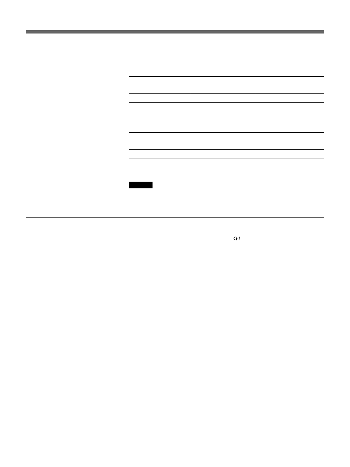
Wenn Sie mit einem digitalen Camcorder von Sony (DSR-200P,
DSR-200AP oder DSR-PD100P) aufnehmen
Signale für Im Kassettenspeicher Auf dem Band
Indexsuche
Datumssuche Ja Ja
Fotosuche Ja Ja
Wenn Sie mit dem DSR-40P aufnehmen
Signale für Im Kassettenspeicher Auf dem Band
Indexsuche
Datumssuche Nein Ja
Fotosuche Nein Nein
a) Die Signale für die Indexsuche werden aufgezeichnet, wenn Sie im
Hinweis
Wenn Sie mit dem DSR-40P aufnehmen, enthalten die Signale für die
Indexsuche keine Informationen zum Wochentag.
Hinweise zum Kassettenspeicher
a)
a)
Nein Nein
Ja Ja
Stoppmodus die Aufnahme starten.
•Bei einer Kassette mit der Markierung speichert der Kassettenspeicher
bis zu 135 Indexsignale. Die Anzahl variiert je nach Anteil der Index-,
Datums- und Fotodaten auf einem Band. Der DSR-40P kann bis zu 16
Kbit Daten im Kassettenspeicher ablegen und daraus abrufen.
•Zum Suchen von Aufnahmen, für die keine Daten im Kassettenspeicher
abgelegt werden konnten, oder zum Suchen in der Reihenfolge der
tatsächlichen Position der Aufnahmen auf dem Band setzen Sie
CASSETTE MEMORY SEARCH im Menü auf OFF. Genauso können
Sie auf einem Band ohne Kassettenspeicher nach einer Aufnahme
suchen.
Weitere Informationen zu den Menüfunktionen entnehmen Sie bitte der
Bedienungsanleitung des DSR-40P.
39
Page 40
Bedienung
Hinweise
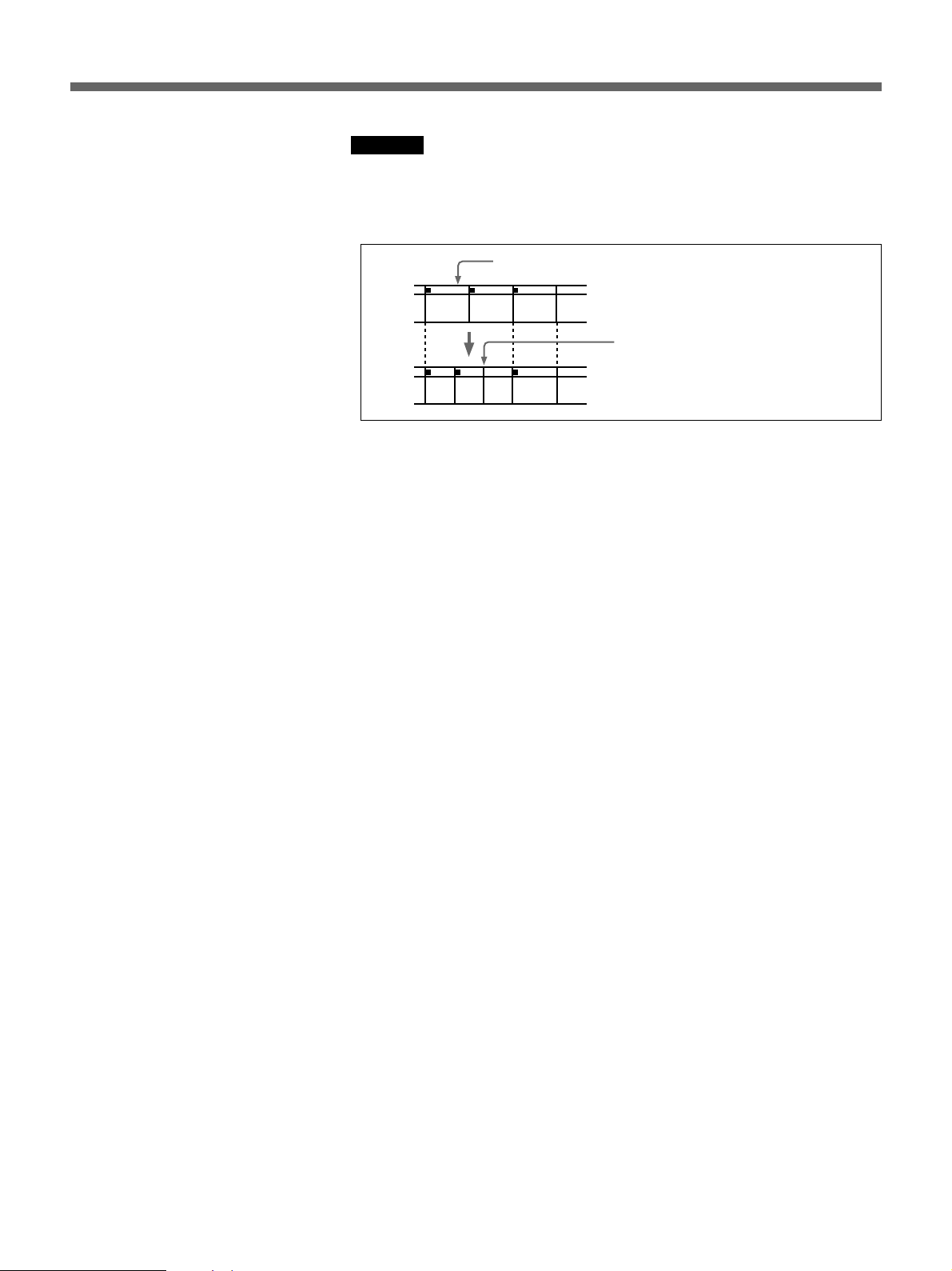
•Bei jeder Aufnahme wird am Anfang eine Indexmarkierung gesetzt.
Wenn Sie den Anfang einer frühereen Aufnahme mit einer nenen
Aufnahme überspielen, können Sie die erste Aufnahme nicht mehr per
Indexmarkierung lokalisieren.
Indexsignal
ABC
Wenn D den Anfang von
B überspielt...
...kann B nicht mehr gesucht werden.
ABCD
•Sie können Indexsignale nicht nach der Aufnahme hinzufügen.
Wenn Sie Indexsignale ausschließlich für das automatische Wiederholen
hinzufügen möchten, starten Sie die Aufnahme an der Stelle, an der ein
Indexsignal gesetzt werden soll.
•Sie können Indexsignale nach dem Aufnehmen nicht löschen.
Wenn Sie Indexsignale für das automatische Wiederholen löschen
wollen, setzen Sie INDEX WRITE im Menü auf OFF. Überspielen Sie
dann das Indexsignal, das gelöscht werden soll.
•Die Suche erfolgt möglicherweise nicht korrekt, wenn die Signale nicht
mit einem digitalen Videogerät von Sony aufgezeichnet wurden.
Weitere Informationen zu den Menüfunktionen entnehmen Sie bitte der
Bedienungsanleitung des DSR-40P.
40
Page 41
Anzeigen von Bandinformationen
Wenn Sie ein Band mit einem digitalen Camcorder von Sony (DSR-200P/
200AP/PD100P) aufnehmen, können Camcorder-Daten (Verschlußzeit,
Program AE-Modus, Weißabgleichswert, Blende und Gain) auf dem Band
aufgezeichnet werden. Sie können diese Daten während der Wiedergabe
auf dem DSR-40P anzeigen lassen.
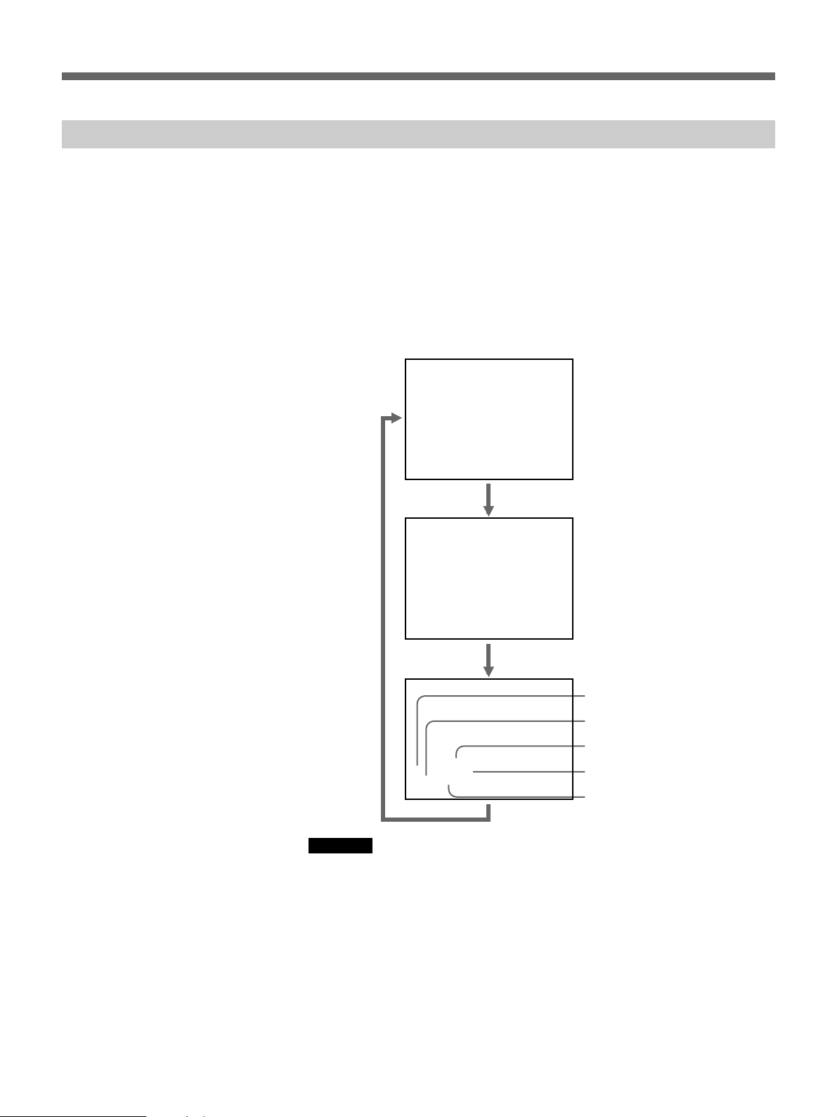
Drücken Sie DATA CODE während der Wiedergabe.
Mit jedem Tastendruck auf DATA CODE wechselt die Anzeige
folgendermaßen.
Keine Datenanzeige
Datum und
Uhrzeit der
Aufnahme
1999 / 12 / 25
12:59 AM LINE
Einstellungen
des SonyCamcorders
Verschlußzeit
Blende
Weißabgleich
Program AE-Modus
Gain
Hinweise
AWB
60 MANUAL
F 1.6 0 dB
•Wenn die Informationen nicht aufgezeichnet wurden, erscheint statt
dessen “- - -”.
•Die Camcorder-Daten, die vom DSR-40P auf dem Bildschirm angezeigt
werden, unterscheiden sich teilweise von den Daten, die der digitale
Camcorder anzeigt.
41
Page 42

Bedienung
Technische Daten
Fernsteuerung Über ein 3 m langes Fernsteuerkabel mit Stereo-
Ministecker
Stromversorgung 5 V Gleichstrom (über den DSR-40P)
Leistungsaufnahme
50 mW
Lagerungstemperatur
–20 °C bis 60 °C
Betriebstemperatur
5 °C bis 40 °C
Abmessungen (B/H/T)
90 × 46 × 182 mm (ohne Fernsteuerkabel)
Masse 360 g
Im Lieferumfang Bedienungsanleitung (1)
Änderungen, die dem technischen Fortschritt dienen, bleiben vorbehalten.
42
Page 43

Italiano
Indice
Per i clienti in Europa
Questo prodotto contrassegnato CE è conforme a quanto
espresso dalla Direttiva EMC (89/336/EEC) emessa dalla
Commissione della Comunità Europea.
La conformità a questa Direttiva implica la conformità ai
seguenti standard europei:
• EN55103-1: Interferenza elettromagnetica (Emissione)
• EN55103-2: Suscettività elettromagnetica (Immunità)
Questo prodotto è stato progettato per essere utilizzato nei
seguenti ambienti elettromagnetici:
E1 (residenziale), E2 (commerciale e industria leggera), E3
(esterni urbani) e E4 (ambienti EMC controllati, es. studio
televisivo).
Generali........................................................... 43
Identificazione delle parti .............................. 44
Collegamenti................................................... 45
Funzionamento............................................... 46
Ricerca jog/shuttle...........................................46
Ricerca mediante la funzione di indice ........... 47
Visualizzazione delle informazioni memorizzate
sul nastro .................................................... 50
Caratteristiche tecniche ................................ 51
Generali
L’unità di controllo a distanza DSRM-20 è stata
progettata per controllare il DSR-40P. Quando è usata
con il DSR-40P, la DSRM-20 aggiunge le seguenti
funzioni.
Ricerca jog/shuttle
Con la manopola shuttle, l’immagine di riproduzione
può essere vista sia ad una velocità compresa fra –17 e
+17 volte la velocità normale sia nel modo di fermo
immagine. Con la manopola jog, l’immagine di
riproduzione può essere vista sia ad una velocità
compresa fra –2 e +2 volte la velocità normale sia nel
modo di fermo immagine.
Ricerca di indice
È possibile trovare rapidamente i punti desiderati
usando i segnali di indice o le informazioni di modo di
data e foto. I segnali di indice sono registrati sul nastro
e le informazioni di modo di data e foto sono registrate
nella memoria della cassetta (se la cassetta è dotata di
memoria).
Visualizzazione delle informazioni
memorizzate sul nastro
È possibile visualizzare le informazioni relative alla
camcorder durante la riproduzione se il nastro è stato
utilizzato per la ripresa sulla camcorder DSR-200P/
200AP/PD1P/PD100P.
IT
Italiano
43
Page 44
Parts Identification
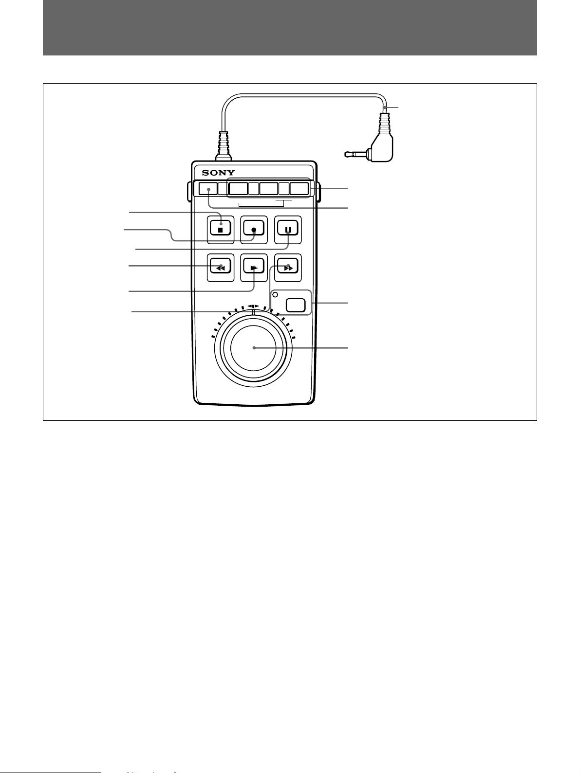
Identificazione delle parti
!¡ Cavo di collegamento
=
PLAY
1 Tasto STOP
2 Tasto REC
3 Tasto PAUSE
4 Tasto REW
5 Tasto PLAY
6 Tasto F FWD
DATA CODE SEARCH MODE
STOP REC
REW
1 Tasto di arresto (STOPp)
Premerlo per fermare il nastro.
2 Tasto di registrazione (REC r)
Per eseguire la registrazione, premere questo tasto per
porre il videoregistratore nel modo di pausa di
registrazione, e quindi premere il tasto PAUSE P 3.
3 Tasto di pausa (PAUSE P)
Premerlo per fare una pausa durante la registrazione o
la riproduzione. Premerlo di nuovo per disattivare il
modo di pausa.
4 Tasto di riavvolgimento (REW 0)
Quando il videoregistratore si trova nel modo di
arresto, premere questo tasto per riavvolgere il nastro.
Quando il nastro è in fase di riproduzione o di
riavvolgimento, tenere premuto questo tasto per
riavvolgere il nastro visualizzando l’immagine di
riproduzione.
5 Tasto di riproduzione (PLAY ()
Premerlo per riprodurre il nastro.
=
0 Tasti SEARCH MODE
9 Tasto DATA CODE
PAUSE
F FWD
JOG/SHUTTLE
8 Tasto JOG/SHUTTLE e indicatore
7 Manopole di ricerca
6 Tasto di avanzamento rapido (F FWD ))
Quando il videoregistratore si trova nel modo di
arresto, premere questo tasto per far avanzare
rapidamente il nastro.
Quando il nastro è in fase di riproduzione o di
avanzamento rapido, tenere premuto questo tasto per
far avanzare rapidamente il nastro visualizzando
l’immagine di riproduzione.
7 Manopole di ricerca
La rotazione in senso orario riproduce il nastro in
avanti mentre la rotazione in senso antiorario riproduce
il nastro all’indietro.
Manopola shuttle (esterna): La velocità di
riproduzione è determinata dalla posizione della
manopola, nella gamma compresa fra –17 e +17
volte la velocità normale. Quando la manopola
shuttle si trova nella sua posizione centrale, si
ottiene un fermo immagine.
Manopola jog (interna): La velocità di riproduzione è
determinata dalla velocità di rotazione della
manopola, nella gamma compresa fra –2 e +2 volte
la velocità normale.
44
Page 45

Nota
La manopola jog funziona solo quando la manopola
shuttle è nella sua posizione di scatto centrale.
8 Tasto di modo jog/shuttle (JOG/SHUTTLE)
e indicatore
Premere il tasto per riprodurre il nastro nel modo jog o
shuttle. L’indicatore si illumina e il DSR-40P entra in
modo jog o shuttle.
Premere un qualsiasi tasto di trasporto del nastro per
ritornare al modo di funzionamento normale.
9 Tasto di visualizzazione informazioni
(DATA CODE)
Premere questo tasto per visualizzare le informazioni
memorizzate sul nastro sullo schermo del monitor.
Per i dettagli, vedere “Visualizzazione delle informazioni
memorizzate sul nastro” a pagina 50.
0 Tasti di modo di ricerca (SEARCH MODE
= o +)
Premere questi tasti per cercare le scene usando la
funzione di indice.
Per i dettagli, vedere “Ricerca mediante la funzione di
indice” a pagina 47.
!¡ Cavo di collegamento (con minispina
stereo)
Collegare questo cavo al connettore CONTROL S del
DSR-40P.
Collegamenti
Collegare questa unità al connettore CONTROL S del
DSR-40P.
L’alimentazione viene fornita automaticamente a
questa unità dal DSR-40P.
Connettore CONTROL S
DSRM-20
45
Page 46
Operation
Funzionamento
Ricerca jog/shuttle
I tasti di trasporto del nastro di questa unità funzionano nello stesso modo
dei tasti sul DSR-40P. Le operazioni di registrazione, riproduzione,
avanzamento rapido, riavvolgimento e pausa possono essere controllate a
distanza da questa unità.
Usando le manopole di ricerca, è possibile eseguire un’operazione di
ricerca nel modo jog o shuttle.
Modo jog: La velocità di riproduzione è determinata dalla velocità di
rotazione della manopola jog, nella gamma compresa fra –2 e +2 volte
la velocità normale.
Modo shuttle: La velocità di riproduzione è determinata dalla posizione
della manopola shuttle, nella gamma compresa fra –17 e +17 volte la
velocità normale. Quando la manopola shuttle si trova nella sua
posizione centrale, si ottiene un fermo immagine.
Nota
Quando si usa l’unità immediatamente dopo averla accesa, accertarsi
innanzitutto di riportare la manopola shuttle nella sua posizione centrale.
DUP
COUNTER
AUDIO
TAPE
SELECT
TC
CH-1/2
CH-3/4
MONITOR
MIX
TIMER
REMOTE
REPEAT
OFF
MENU
REC
LOCAL
SET
INPUT
SELECT
COUNTER
REMAIN
Connettore CONTROL S
1
2-
1)
2-
2)
DSRM-20
1 Premere il tasto JOG/SHUTTLE per attivare il modo jog o shuttle.
46
L’indicatore JOG/SHUTTLE si illumina.
Page 47

2 Per eseguire la ricerca nel modo jog
1) Regolare la manopola shuttle nella posizione di scatto centrale.
2) Girare la manopola jog.
Ogni volta che si gira la manopola jog per un certo tratto, viene
eseguita la ricerca in modo jog di un fotogramma alla volta, in
avanti o all’indietro.
Per eseguire la ricerca nel modo shuttle
Girare la manopola shuttle.
Un’immagine di riproduzione appare alla velocità determinata dalla
posizione di rotazione della manopola. Quando la manopola è regolata
nella posizione di scatto centrale, il nastro si ferma e si ottiene un
fermo immagine.
Per uscire dal modo jog o shuttle
Premere un qualsiasi tasto di trasporto del nastro.
L’indicatore JOG/SHUTTLE si spegne, e il registratore o il lettore passa
all’operazione corrispondente al tasto premuto.
Ricerca mediante la funzione di indice
Tre tipi di ricerca sono possibili con questa unità.
– Ricerca dell’inizio delle registrazioni: Ricerca di indice
– Ricerca di un punto sul nastro in cui la data di registrazione cambia:
Ricerca di data
– Ricerca di scene registrate nel modo foto con una camcorder digitale:
Ricerca di foto
Quando si usa una cassetta dotata di memoria
Se la cassetta è dotata di memoria, le registrazioni vengono elencate
cronologicamente nell’ordine in cui sono state eseguite. È possibile
effettuare la ricerca utilizzando questa lista cronologica.
1 Premere SEARCH MODE per selezionare il tipo di ricerca: INDEX,
DATE o PHOTO SEARCH.
La lista cronologica appare sullo schermo del monitor.
µ
Quando si seleziona INDEX SEARCH
(continua)
47
Page 48

Operation
Funzionamento
2 Premere = o + per selezionare una registrazione.
Il videoregistratore avvia la ricerca e quando individua la registrazione
inizia la riproduzione. Durante la ricerca di foto il videoregistratore
entra in modo di pausa.
Quando si usa una cassetta priva di memoria
Quando si usa una cassetta priva di memoria, il videoregistratore effettua
la ricerca seguendo l’ordine effettivo delle posizioni delle registrazioni,
indipendentemente dall’impostazione di CASSETTE MEMORY
SEARCH nel menu del DSR-40P.
Per ulteriori informazioni sulle operazioni nei menu, fare riferimento alle
istruzioni per l’uso del DSR-40P.
1 Premere SEARCH MODE per selezionare il tipo di ricerca.
Registrazione dei segnali
INDEX 0
SEARCH
Quando si seleziona INDEX SEARCH
2
Premere più volte = o + per individuare la registrazione desiderata.
Il videoregistratore avvia la ricerca all’indietro o in avanti finché il
numero di indice raggiunge lo zero, quindi riproduce la registrazione.
Durante la ricerca di foto il videoregistratore entra in modo di pausa.
Quando viene premuto REC il videoregistratore contrassegna il nastro.
Vi sono tre diversi segnali per ogni metodo di ricerca. Il tipo di segnale
registrato e il punto in cui viene registrato (sul nastro o nella memoria della
cassetta) dipende dall’apparecchiatura video usata per la registrazione. Si
noti che se i segnali per un determinato tipo di ricerca non vengono
registrati, non è possibile effettuare quel tipo di ricerca.
Quando si registra con una camcorder digitale Sony (DSR200P, DSR-200AP o DSR-PD100P)
48
Segnali per Nella memoria della cassetta Sul nastro
Ricerca di indice
Ricerca di data Sì Sì
Ricerca di foto Sì Sì
a) I segnali per la ricerca di indice vengono registrati quando si avvia la
registrazione nel modo di arresto.
a)
No No
Page 49
Memoria della cassetta
Quando si registra sul DSR-40P
Segnali per Nella memoria della cassetta Sul nastro
Ricerca di indice
Ricerca di data No Sì
Ricerca di foto No No
a) I segnali per la ricerca di indice vengono registrati quando si avvia la
registrazione nel modo di arresto.
Nota
a)
Sì Sì
Quando si registra sul DSR-40P, i segnali per la ricerca di indice non
dispongono di informazioni sul giorno della settimana.
•Se si usa una cassetta con il marchio , la memoria della cassetta può
memorizzare fino a 135 segnali di indice. (Il numero varia in base alla
combinazione delle dimensioni dei dati di indice, di data e di foto
memorizzati sul nastro.) Il DSR-40P è in grado di memorizzare e reperire
fino a 16 kbit di memoria della cassetta.
•Per localizzare le registrazioni i cui segnali non possono essere
memorizzati nella memoria della cassetta, o per localizzare le
registrazioni secondo l’ordine di posizione sul nastro, impostare
CASSETTE MEMORY SEARCH nel menu su OFF. È possibile usare lo
stesso procedimento per cercare una registrazione su una cassetta priva di
memoria.
Per ulteriori informazioni sulle operazioni nei menu, fare riferimento alle
istruzioni per l’uso del DSR-40P.
Note
•All’inizio di ogni programma viene assegnato un indice. Se si registra un
altro programma sopra l’inizio del primo programma, non sarà più
possibile localizzare il programma originale.
Segnale di indice
Se D viene registrato
ABC
sopra l’inizio di B...
B non può essere cercato.
ABCD
•Non è possibile aggiungere indici dopo la registrazione.
Per aggiungere indici solo per la ripetizione automatica, avviare la
registrazione dal punto in cui si desidera iniziare ad assegnare gli indici.
•Non è possibile cancellare gli indici dopo la registrazione.
Per cancellare gli indici per la ripetizione automatica, impostare INDEX
WRITE nel menu su OFF. Quindi registrare sopra il segnale di indice che
si desidera cancellare.
49
Page 50
Funzionamento
Operation
•La ricerca potrebbe non avvenire in maniera corretta se i segnali non sono
stati registrati con un’apparecchiatura video digitale di marca Sony.
Per ulteriori informazioni sulle operazioni nei menu, fare riferimento alle
istruzioni per l’uso del DSR-40P.
Visualizzazione delle informazioni memorizzate sul nastro
Se si registra su un nastro usando una camcorder digitale Sony DSR-200P/
200AP/PD100P, i dati della camcorder (la velocità dell’otturatore, il modo
di esposizione automatica programmata, il bilanciamento del bianco, il
diaframma ed il guadagno) possono essere registrati sul nastro. È possibile
controllare questi dati durante la riproduzione sul DSR-40P.
Premere DATA CODE durante la riproduzione.
Ogni volta che si preme DATA CODE, la visualizzazione cambia come
mostrato di seguito.
Visualizzazione
dati disattivata
Data e ora di
registrazione
1999 / 12 / 25
12:59 AM LINE
Impostazioni della
camcorder Sony
Velocità dell’otturatore
Diaframma
50
Bilanciamento del bianco
Note
AWB
60 MANUAL
F 1.6 0 dB
Modo di esposizione automatica
programmata
Guadagno
•Se nessuna informazione è stata registrata, appare l’indicazione “- - -”.
•I dati della camcorder visualizzati sullo schermo del monitor dal DSR-
40P sono in parte diversi da quelli mostrati dalla camcorder digitale.
Page 51

Caratteristiche tecniche
Controllo a distanza
Alimentazione CC a 5 V (fornita dal DSR-40P)
Consumo 50 mW
Temperatura di deposito
Temperatura di impiego
Dimensioni (l/a/p) 90 × 46 × 182 mm
Massa Circa 360 g
Accessorio in dotazione
Disegno e caratteristiche tecniche soggetti a modifiche senza preavviso.
Minispina stereo (con cavo applicato, lunghezza di 3
m)
Da –20°C a +60°C
Da 5°C a 40°C
escluso il cavo interfaccia
Manuale di istruzioni (1)
51
Page 52

Sony Corporation
Printed in Japan
 Loading...