

SONY DSC-S75 Service Manual
DSC-S75
AC-L10A/B/C
AC power adaptor
Power requirements
100 to 240 V AC, 50/60 Hz
Rated output voltage
DC 8.4 V, 1.5 A in operating
mode
Operation temperature
0°C to 40°C (32°F to 104°F)
Storage temperature
–20°C to +60°C
(–4°F to +140°F )
Maximum dimensions
125×39×62 mm
(5×19/16×2 1/2 inches)
(w/h/d)
Mass
Approx. 280 g (10 oz)
SERVICE MANUAL
Level 1
Ver 1.1 2001. 06
SPECIFICATIONS
System
Image device
8.93 mm (1/1.8 type) color
CCD
Lens
3× zoom lens
f = 7 – 21 mm (9/32 – 27/32
inches)
(34 – 102 mm (1 3/8 – 4 1/8
inches) when converted into a
35 mm still camera)
F = 2.0 – 2.5
Exposure control
Automatic exposure, Shutter
speed priority, Aperture
priority, Manual exposure
White balance
Automatic, Indoor, Outdoor,
One-push
Data system
Movie: MPEG1
Still: JPEG, GIF (in TEXT
mode, Clip Motion), TIFF
Audio with still image:
MPEG1 (Monaural)
Recording medium
“Memory Stick”
Flash
Recommended recording
distance (ISO is set to AUTO):
0.3m to 3.0m (117/8inches
to 9 feet 10 1/8 inches)
Output connector
A/V OUT (Monaural)
Minijack
Video: 1 Vp-p, 75Ω,
unbalanced, sync negative
Audio: 327 mV (at a 47 kΩ
load)
Output impedance: 2.2 k
USB jack
mini-B
External flash jack
Minijack
LCD screen
Used LCD panel
1.8 type TFT (Thin Film
Transistor active matrix) drive
Total number of dots
123 200 (560×220) dots
General
Used battery pack
NP-FM50
Power requirements
7.2 V
Power consumption
(during recording)
3.0 W
Operation temperature
0°C to 40°C
(32°F to 104°F)
Storage temperature
–20°C to +60°C
Ω
(–4°F to +140°F)
Maximum dimensions
117×71×64 mm
(4 5/8×27/8×2 5/8 inches)
(w/h/d)
Mass
Approx. 462 g (1 lb)
(including battery pack NPFM50, “Memory Stick,”
shoulder strap and lens cap
etc.)
Built-in microphone
Electret condenser microphone
Built-in speaker
Dynamic speaker
AEP Model
UK Model
Accessories
A/V connecting cable (1)
NP-FM50 battery pack (1)
AC-L10A AC power adaptor
(1)
Power cord (1)
USB cable (1)
Lens cap (1)
Lens cap strap (1)
Shoulder strap (1)
“Memory Stick” (8 MB) (1)
CD-ROM (2)
Operating Instructions (1)
Design and specifications are
subject to change without
notice.
NP-FM50 battery pack
Used battery
Lithium ion battery
Maximum voltage
DC 8.4 V
Nominal voltage
DC 7.2 V
Capacity
8.5 Wh (1 180 mAh)
DIGITAL STILL CAMERA

SAFETY-RELATED COMPONENT WARNING!!
COMPONENTS IDENTIFIED BY MARK 0 OR DOTTED
LINE WITH MARK 0 ON THE SCHEMATIC DIAGRAMS
AND IN THE PARTS LIST ARE CRITICAL TO SAFE
OPERATION. REPLACE THESE COMPONENTS WITH
SONY PARTS WHOSE PART NUMBERS APPEAR AS
SHOWN IN THIS MANUAL OR IN SUPPLEMENTS PUBLISHED BY SONY.
SAFETY CHECK-OUT
After correcting the original service problem, perform the following
safety checks before releasing the set to the customer.
1. Check the area of your repair for unsoldered or poorly-soldered connections. Check the entire board surface for solder
splashes and bridges.
2. Check the interboard wiring to ensure that no wires are
“pinched” or contact high-wattage resistors.
3. Look for unauthorized replacement parts, particularly transistors, that were installed during a previous repair. Point them
out to the customer and recommend their replacement.
4. Look for parts which, though functioning, show obvious signs
of deterioration. Point them out to the customer and recommend their replacement.
5. Check the B+ voltage to see it is at the values specified.
6. Flexible Circuit Board Repairing
• Keep the temperature of the soldering iron around 270 ˚C
during repairing.
• Do not touch the soldering iron on the same conductor of
the circuit board (within 3 times).
• Be careful not to apply force on the conductor when sol-
dering or unsoldering.
– 2 –

TABLE OF CONTENTS
Section Title Page
SERVICE NOTE................................................................... 4
Self-diagnosis Display .......................................................... 5
1. MAIN PARTS
1. Ornamental Parts .......................................................... 6
2. DISASSEMBLY
2-1. Cabinet (Rear) Block Assembly .................................... 7
2-2. Lens Block Assembly .................................................... 7
2-3. DM-101 Board ............................................................... 8
2-4. CK-103 Board ................................................................ 8
2-5. Control Switch Block (Zoom), LCD Panel
(Character Display) ....................................................... 8
2-6. LCD Module................................................................... 8
3. REPAIR PARTS LIST
3-1. Exploded Views ............................................................. 9
3-1-1. Main Section............................................................. 9
3-1-2. Cabinet (Front) Block Assembly .............................. 10
3-1-3. Lens Block Assembly ............................................... 11
3-1-4. Cabinet (Rear) Block Assembly............................... 12
4. GENERAL
Introduction.............................................................................. 13
Identifying the Parts................................................................. 14
Preparing the Power Supply.................................................... 14
Setting the Date and Time....................................................... 15
Inserting the “Memory Stick” ................................................... 16
Basic operations ...................................................................... 16
Recording Still Images ............................................................ 16
Recording Moving Images....................................................... 18
Playing Back Still Images ........................................................ 19
Playing Back Moving Images .................................................. 19
Viewing Images Using a Personal Computer ......................... 19
Image File Storage Destinations and Image Files.................. 21
Before Performing Advanced Operations ............................... 22
Various Recording ................................................................... 24
Various Playback ..................................................................... 27
Editing ..................................................................................... 28
Additional Information.............................................................. 31
Troubleshooting ....................................................................... 32
Warning and Notice Messages ............................................... 34
Self-diagnosis Display ............................................................. 34
Display Window Indicators ...................................................... 35
LCD Screen Indicators ............................................................ 35
– 3 –
SERVICE NOTE
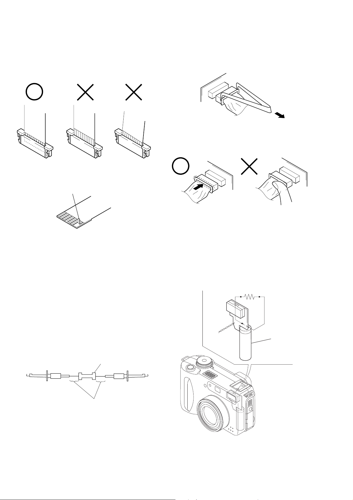
• NOTE FOR REPAIR
Make sure that the flat cable and flexible board are not cracked of
bent at the terminal.
Do not insert the cable insufficiently nor crookedly.
Cut and remove the part of gilt
which comes off at the point.
(Be careful or some pieces of
gilt may be left inside)
When remove a connector, don’t pull at wire of connector.
It is possible that a wire is snapped.
When installing a connector, don’t press down at wire of connector.
It is possible that a wire is snapped.
[Discharging of the FLASH unit’s charging capacitor]
The charging capacitor of the FLASH unit is charged up to the
maximum 300 V potential.
There is a danger of electric shock by this high voltage when the
battery is handled by hand. The electric shock is caused by the
charged voltage which is kept without discharging w hen the main
power of the DSC-S75 is simply turned off. Therefore, the remaining voltage must be discharged as described below.
Preparing the Short Jig
T o preparing the short jig. a small clip is attached to each end of a
resistor of 1 kΩ /1 W (1-215-869-11).
Wrap insulating tape fully around the leads of the resistor to prevent electrical shock.
1 kΩ/1 W
Wrap insulating tape.
Discharging the Capacitor
Short-circuit between the positive and the negative terminals of
charged capacitor with the short jig about 10 seconds.
R: 1 kΩ/1W
(Part code:
1-215-869-11)
Capacitor
– 4 –
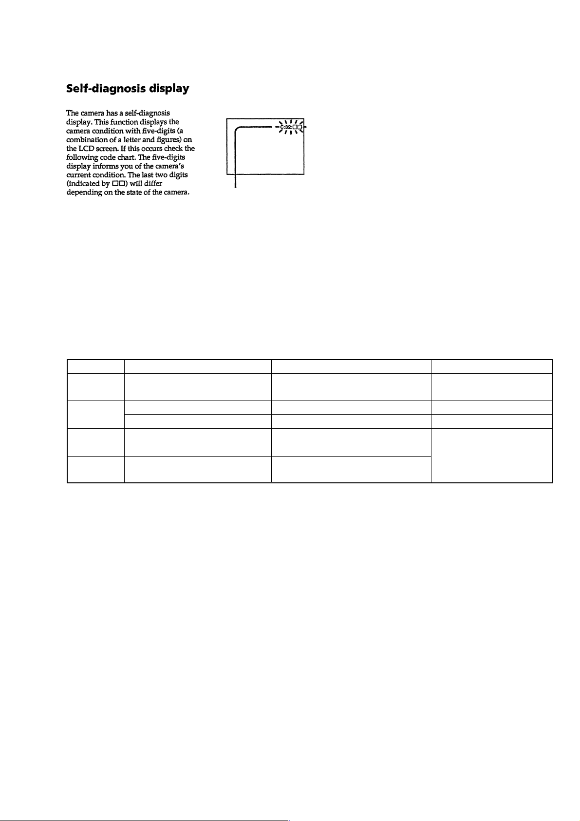
[Description on Self-diagnosis Display]
Self-diagnosis display
• C: ss: ss
You can reverse the camera malfunction yourself. (However , contact your Sony dealer or local
authorized Sony service facility
when you cannot recover from
the camera malfunction.)
• E: ss: ss
Contact your Sony dealer or local authorized Sony service facility.
Display Code
C:32:ss
C:13:ss
E:61:ss
E:91:ss
Countermeasure
Turn the power off and on again.
Format the “Memory stick”.
Insert a new “Memory Stick”.
Checking of lens drive circuit.
Checking of flash unit or replacement
of flash unit.
Cause
Trouble with hardware.
Unformatted memory stick is inserted.
Memory stick is broken.
When failed in the focus and zoom
initialization.
Abnormality when flash is being
charged.
Caution Display During Error
SYSTEM ERROR
FORMAT ERROR
MEMORY STICK ERROR
—
– 5 –
DSC-S75
1. MAIN PARTS
Note:
• Items marked “*” are not stocked since they are seldom required for routine service.
Some delay should be anticipated when ordering these items.
• The parts numbers of such as a cabinet are also appeared in this section.
Refer to the parts number mentioned below the name of parts to order.
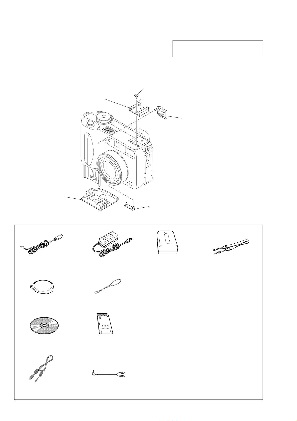
1. ORNAMENTAL PARTS
Interior lock process (M2)
3-069-159-01
Accessory shoe
3-067-469-11
The components identified by mark 0 or dotted
line with mark 0 are critical for safety.
Replace only with part number specified.
DC (IN) cover
3-068-654-01
(When change it, need to
dismantle the set.)
Battery lid
3-068-640-01
Checking supplied accessories.
Power cord (1)
0 1-769-608-11 (AEP)
0 1-783-374-11 (UK)
Lens cap (1)
X-3951-672-1
CD-ROM
(SPVD-004 USB driver) (1)
3-006-676-01
AC power adaptor
AC-L10A (1)
0 1-475-599-11
Lens cap strap (1)
3-067-797-01
“Memory Stick”
(8 MB) (1)
CPC lid
3-068-652-01
Battery pack
NP-FM50 (1)
Shoulder strap (1)
3-987-015-01
Other accessories
3-068-187-11 MANUAL, INSTRUCTION (ENGLISH)
3-068-187-21 MANUAL, INSTRUCTION
3-068-187-31 MANUAL, INSTRUCTION
3-068-187-41 MANUAL, INSTRUCTION
3-068-187-61 MANUAL, INSTRUCTION
(FRENCH, GERMAN) (AEP)
(SPANISH, PORTUGUESE) (AEP)
(ITALIAN, DUTCH) (AEP)
(SWEDISH, RUSSIAN) (AEP)
USB cable (1)
1-757-293-11
A/V connecting cable (1)
1-783-738-11
– 6 –

2. DISASSEMBLY
• This set can be disassembled in the order shown below.
DSC-S75
2-1. CABINET (REAR) BLOCK
ASSEMBLY (Page 7)
DSC-S75
2-2. LENS BLOCK ASSEMBLY
(Page 7)
2-3. DM-101 BOARD
(Page 8)
2-4. CK-103 BOARD
(Page 8)
2-5. CONTROL SWITCH BLOCK (ZOOM),
LCD PANEL (CHARACTER DISPLAY)
(Page 8)
Note: Follow the disassembly procedure in the numerical order given.
2-1. CABINET (REAR) BLOCK ASSEMBLY
8 Two flexible boards
7 Cabinet (rear)
(CN402, 403)
block assembly
5 Screw
(M2)
4 Two screws
(M2)
1 Screw
(M2)
2-6. LCD MODULE
(Page 8)
2-2. LENS BLOCK ASSEMBLY
2 Flexible board
(CN707)
3 Flexible board
(CN701)
1 Harness
(CN251)
6 Open the battery lid.
2 Screw
(M2)
9 Flexible board
(CN801)
3 Two screws
(M2)
– 7 –
7 Lens block
assembly
6 Screw
(M2)
4 Harness
(CN706)
5 Flexible
board
(CN703)
8 Harness
(CN252)
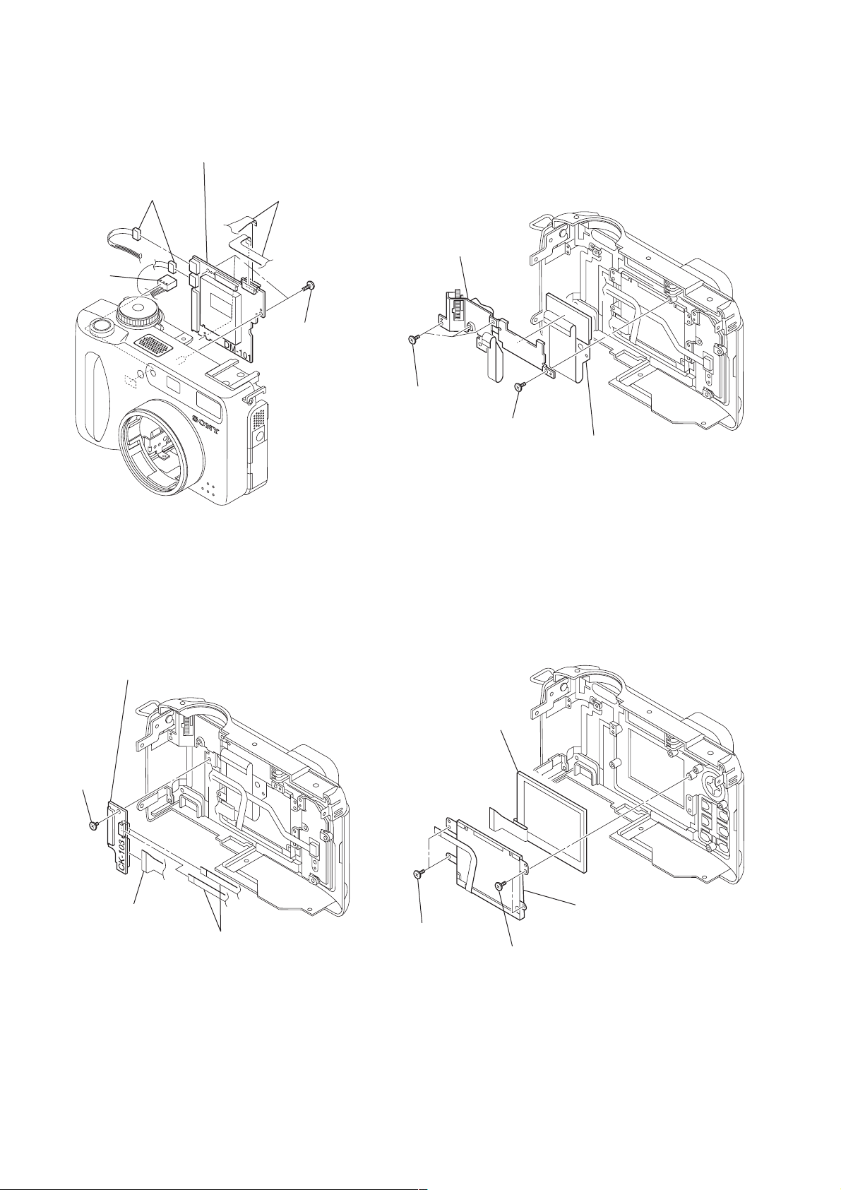
2-3. DM-101 BOARD 2-5. CONTROL SWITCH BLOCK (ZOOM),
LCD PANEL (CHARACTER DISPLAY)
3 DM-101 board
5 DC-IN
connector
1 Two harness
(CN001, 002)
4 Two flexible boards
(CN752, 754)
2 Three
screws
(M1.7 × 5)
3 Control switch
block (zoom)
1 Three screws
(M1.7 × 4)
2 Screw
(M1.7 × 4)
4 LCD panel
(character display)
2-4. CK-103 BOARD 2-6. LCD MODULE
4 CK-103 board
4 LCD module
3 Screw
(M1.7)
1 Flexible board
(CN962)
2 Two flexible boards
(CN961, 964)
1 Two screws
(M1.7 × 4)
2 Two screws
(M1.7 × 4)
3 Light guide plate block
– 8 –
3-1. EXPLODED VIEWS
NOTE:
• -XX and -X mean standardized parts, so they may
have some difference from the original one.
• Items marked “*” are not stocked since they are
seldom required for routine service. Some delay
should be anticipated when ordering these items.
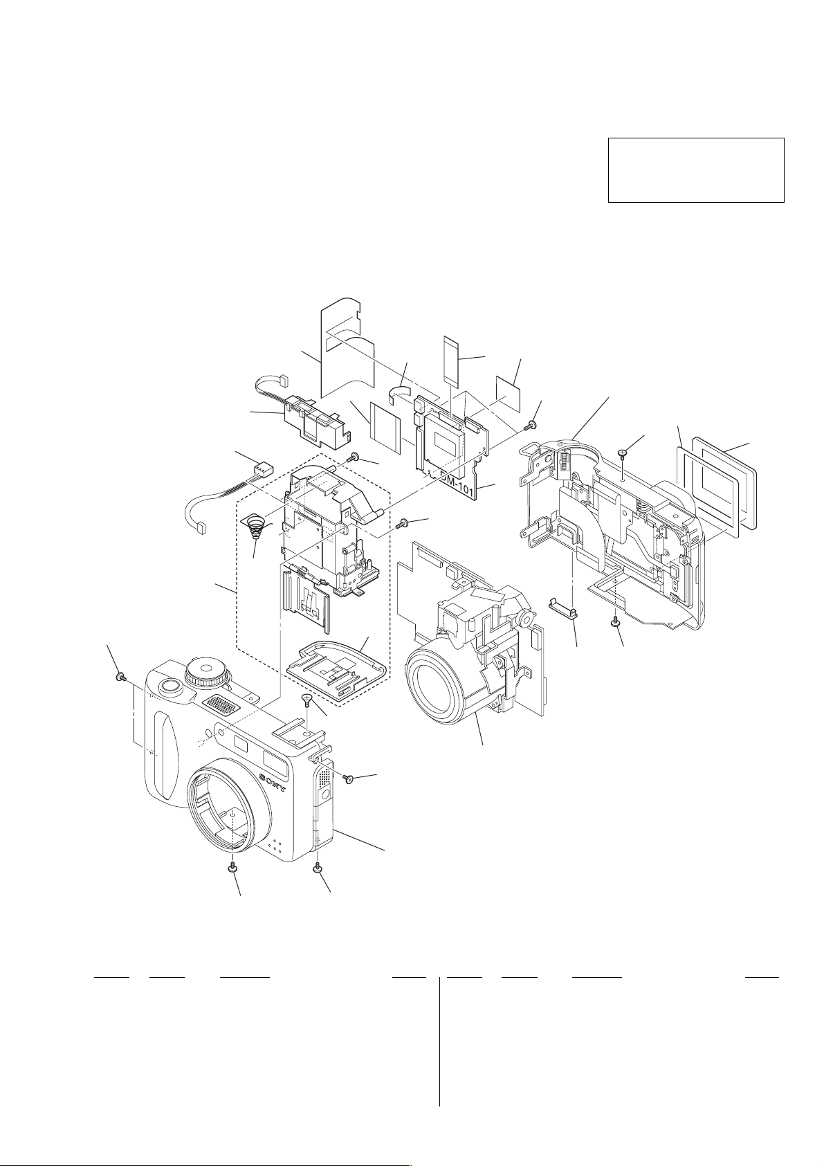
3-1-1. MAIN SECTION
3. REPAIR PARTS LIST
• The mechanical parts with no reference number in
the exploded views are not supplied.
• Accessories are given in the last of the electrical
parts list.
DSC-S75
Ver 1.1 2001. 06
The components identified by mark
0 or dotted line with mark 0 are
critical for safety.
Replace only with part number specified.
12
7
BT902
J001
not
supplied
not supplied
9
Cabinet (rear) block assembly
6
(See page 12.)
1
13
10
6
8
6
5
3
1
4
11
1
2
Lens block assembly
(See page 11.)
1
Cabinet (front) block assembly
(See page 10.)
1
Ref. No. Part No. Description Remark Ref. No. Part No. Description Remark
1 3-069-158-01 PROCESS, (M2) INTERIOR LOCK
2 3-069-159-01 PROCESS, (M2) INTERIOR LOCK
3 X-3951-668-1 HOLDER ASSY, BATTERY
4 3-068-640-01 LID, BATTERY
5 3-969-380-01 SPRING, BATTERY
6 3-713-791-11 SCREW (M1.7X5), TAPPING, P2
7 1-681-657-11 FP-036 FLEXIBLE BOARD
8 not supplied DM-101 BOARD, COMPLETE
1
9 1-681-658-11 FP-037 FLEXIBLE BOARD
10 3-068-646-01 LCD WINDOW
11 3-068-652-01 CPC LID
12 3-068-691-01 TAPE MS
13 3-068-658-01 SHEET, WINDOW ADHESIVE
BT902 1-694-816-11 TERMINAL BOARD, BATTERY
J001 1-794-045-61 CONNECTOR, DC-IN
– 9 –
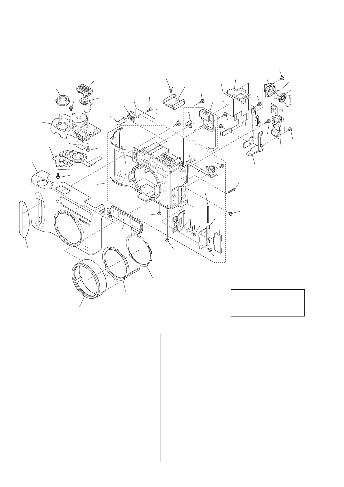
3-1-2. CABINET (FRONT) BLOCK ASSEMBLY
68
66
67
MIC901
72
84
69
70
71
61
73
75
77
79
78
79
85
SP901
54
55
65
64
83
67
56
D902
74
82
63
69
63
not
supplied
not
supplied
not
supplied
62
61
57
59
79
60
58
61
76
61
79
80
not supplied
81
63
53
52
51
Ref. No. Part No. Description Remark Ref. No. Part No. Description Remark
51 3-068-605-01 SCREW, FILTER
52 3-068-609-01 RING, SENSOR
53 3-068-610-01 SPRING, SENSOR
54 3-068-608-01 GRIP
55 3-068-603-01 COVER, CABINET (FRONT)
56 X-3951-665-1 CABINET (FRONT) ASSY
57 3-068-688-01 RETAINER, COVER SHAFT
58 3-068-611-01 COVER, JACK
59 3-968-729-51 SCREW (M2), LOCK ACE, P2
60 3-060-274-01 SCREW, TRIPOD
61 3-713-791-11 SCREW (M1.7X5), TAPPING, P2
62 3-056-233-11 SCREW (M2), LOCK ACE, P2
63 3-069-158-11 PROCESS, (M2) INTERIOR LOCK
64 1-476-666-11 SWITCH BLOCK, CONTROL (MODE)
65 X-3951-667-1 CABINET ASSY, UPPER
66 3-068-631-01 ESCUTCHEON, RELEASE
67 3-061-216-01 ACE (M1.7), SPECIAL HEAD LOCK
68 X-3951-670-1 GRILLE ASSY, MICROPHONE
69 3-948-339-61 TAPPING
70 3-069-159-01 PROCESS, (M2) INTERIOR LOCK
71 3-067-469-11 SHOE, ACCESSORY
72 1-681-662-11 FP-041 FLEXIBLE BOARD
0 73 not supplied FLASH UNIT
74 3-713-791-71 SCREW (M1.7X4)
75 3-068-614-01 ST INSULATING SHEET
76 1-681-661-21 FP-040 FLEXIBLE BOARD
77 3-068-659-01 PLATE, SHOE FIXED
78 3-068-660-01 HOLDER (A), SP
79 3-056-030-31 ACE (M1.7), 0 PLATE 2 MAIN LOCK
80 not supplied JK-211 BOARD, COMPLETE
81 3-069-160-01 PROCESS, (M1.7) INTERIOR LOCK
82 X-3951-666-1 WINDOW ASSY
83 3-062-299-01 SHEET, MICROPHONE
84 3-068-693-01 LED HOLDER
85 3-069-404-01 SPACER, SP
D902 8-719-084-32 DIODE (LED) TLOH20TP
MIC901 1-542-428-21 MICROPHONE
SP901 1-529-857-21 SPEAKER (1.6cm)
The components identified by mark
0 or dotted line with mark 0 are
critical for safety.
Replace only with part number specified.
– 10 –
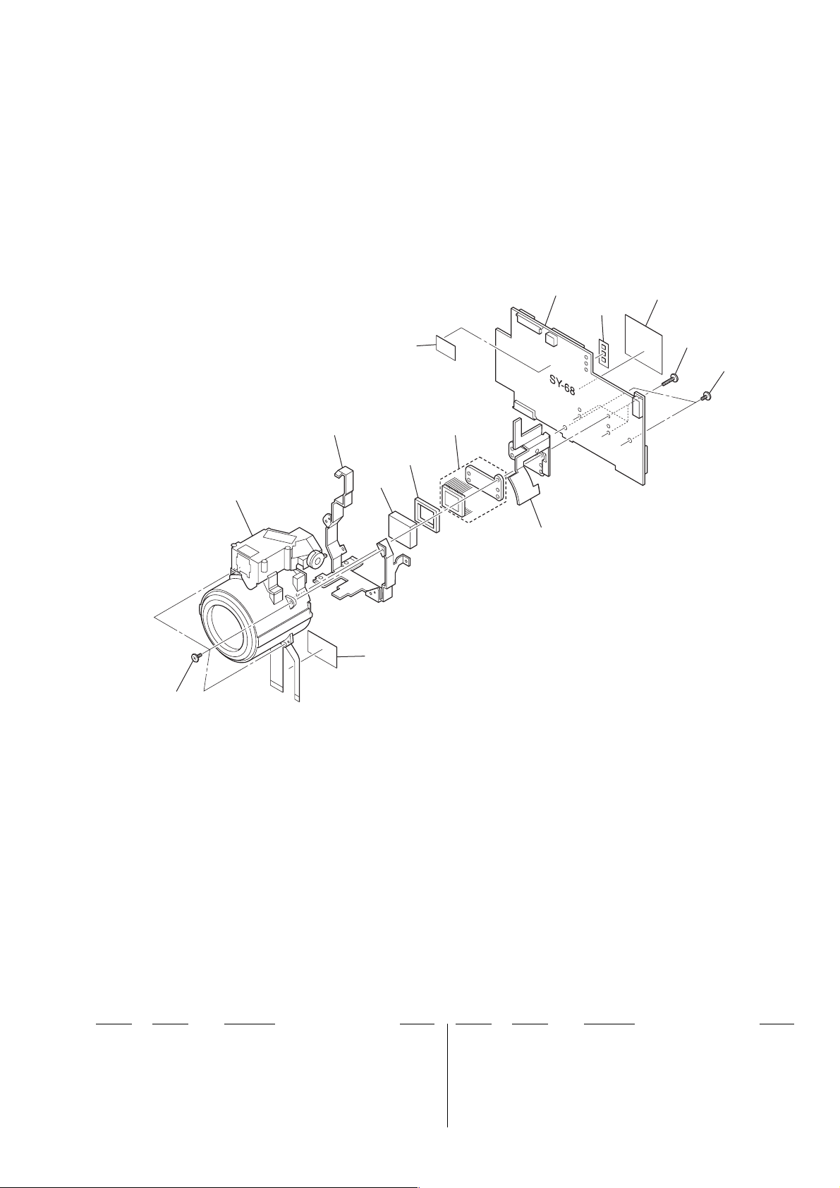
3-1-3. LENS BLOCK ASSEMBLY
101
103
not supplied
105
104
108
IC151
106
not supplied
109
110
107
102
102
Ref. No. Part No. Description Remark Ref. No. Part No. Description Remark
101 not supplied LENS ASSY
102 3-056-030-31 ACE (M1.7), 0 PLATE 2 MAIN LOCK
103 3-068-643-01 FRAME, LENS
104 not supplied FILTER BLOCK, OPTICAL
105 not supplied RUBBER (N), SEAL
107 3-318-203-11 SCREW (B1.7X6), TAPPING
108 3-069-236-01 TAPE (LE)
109 3-068-601-01 DDC RADIATION SHEET
110 3-069-176-01 SHEET, LIGHT INTERCEPTION
IC151 not supplied CCD BLOCK ASSY (CCD IMAGER)
106 not supplied SY-68 BOARD, COMPLETE (SERVICE)
– 11 –
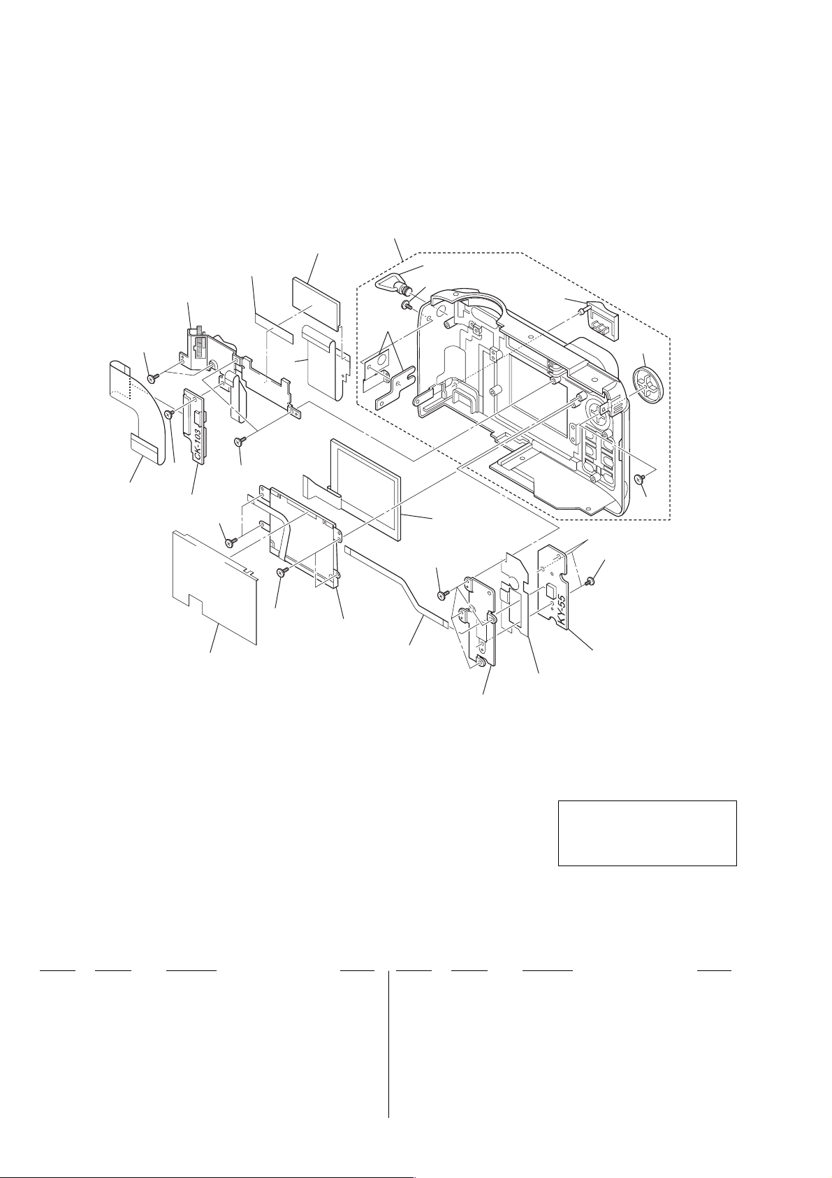
3-1-4. CABINET (REAR) BLOCK ASSEMBLY
not
supplied
LCD902
155
154
156
157
158
159
160
not
supplied
161
151
153
152
154
154
not
supplied
154
D901
164
LCD901
154
not
supplied
162
153
163
not
supplied
The components identified by mark
0 or dotted line with mark 0 are
critical for safety.
Replace only with part number specified.
Ref. No. Part No. Description Remark Ref. No. Part No. Description Remark
151 1-681-659-11 FP-038 FLEXIBLE BOARD
152 not supplied CK-103 BOARD, COMPLETE
153 3-056-030-31 ACE (M1.7), 0 PLATE 2 MAIN LOCK
154 3-713-791-71 SCREW (M1.7X4)
155 1-476-667-11 SWITCH BLOCK, CONTROL (ZOOM)
156 1-681-822-11 FP-389 FLEXIBLE BOARD
157 X-3951-671-1 CABINET (REAR) ASSY
158 3-068-615-01 SHAFT (S), STRAP
159 3-069-158-11 PROCESS, (M2) INTERIOR LOCK
160 3-068-654-01 COVER, DC (IN)
161 3-068-678-01 BUTTON, FUNCTION
162 3-065-177-01 SCREW (1.7X3)
163 not supplied KY-55 BOARD, COMPLETE
164 1-681-660-11 FP-039 FLEXIBLE BOARD
0 D901 not supplied BLOCK, LIGHT GUIDE PLATE (1.8)
LCD901 not supplied INDICATOR MODULE, LIQUID CRYSTAL
LCD902 not supplied DISPLAY PANEL, LIQUID CRYSTAL
(CHARACTER DISPLAY)
– 12 –
 Loading...