

SONY DSCS40ADJ Service Manual
DSC-S60/S80/S90/ST80
Ver 1.0 2005.03
Revision History
Revision History
Link
Link
Before starting adjustments
Before starting adjustments
Adjusting items when replacing main parts and boards
Adjusting items when replacing main parts and boards
CAMERA SECTION ADJUSTMENTS
CAMERA SECTION ADJUSTMENTS
PREPARATIONS BEFORE ADJUSTMENTS
PREPARATIONS BEFORE ADJUSTMENTS
ADJUSTMENT PROGRAMS
ADJUSTMENT PROGRAMS
VIDEO SYSTEM ADJUSTMENTS
VIDEO SYSTEM ADJUSTMENTS
CAMERA SYSTEM ADJUSTMENTS
CAMERA SYSTEM ADJUSTMENTS
LCD SYSTEM ADJUSTMENTS
LCD SYSTEM ADJUSTMENTS
ERROR
ERROR
SECTION 6
ADJUSTMENTS
SERVICE MODE
SERVICE MODE
SERVICE MODE
SERVICE MODE
Auto-ADJ
INITIALIZATION OF DATA
INITIALIZATION OF DATA
•
Use this Service Manual together with the Automatic Adjustment Program (DSC-S60_S80_S90_ST80 Auto-Adj Ver1.[]r
AWB Adjustment Program (S60S80ST80S90AwbAdjustment.exe).
Note:[] (numeric value) of the file name varies depending on the version of Automatic Adjustment Program.
Contents of LEVEL 2 and LEVEL 3 Service Manual
CONTENTS
1. SERVICE NOTE
2. DISASSEMBLY
3. BLOCK DIAGRAMS
4. PRINTED WIRING BOARDS AND
SCHEMATIC DIAGRAMS
5. REPAIR PARTS LIST
OVERALL
POWER
CD-573, SW-446,
ST-122, MC-153, MS-271
CONTROL SWITCH BLOCK
EXPLODED VIEWS
ELECTRICAL PARTS
LEVEL 2
a
a
LEVEL 3
✕
✕
✕
CH-169, SY-126
✕
a
(CH-169, SY-126)
[][]
.exe) and the
DSC-S60/S80/S90/ST80
9-876-869-51
Sony EMCS Co.
2005C0500-1
© 2005.3
Published by DI Technical Support Section

TABLE OF CONTENTS
Section Title Page
6. ADJUSTMENTS
Before Starting Adjustment ·······················································6-1
1-1. Adjusting Items When Replacing
Main Parts and Boards ····················································6-3
6-1. Camera Section Adjustments···········································6-4
1-1. Preparations Before Adjustments ····································6-4
1-1-1.List of Service Tools ························································6-4
1-1-2.Preparations ·····································································6-5
1-1-3.Precautions ······································································6-6
1. Setting the Switch····························································6-6
2. Subjects ···········································································6-6
3. Preparing the Flash Adjustment Box·······························6-7
1-1-4.Using Method of SEUS ···················································6-8
1. Connection·······································································6-8
2. Operation ·········································································6-8
1-1-5.Precaution on Use of SEUS·············································6-8
1-2. Adjustment Programs ······················································6-9
1-2-1.Automatic Adjustment Program ······································6-9
1. Precautions When Using Automatic Adjustment
Program ···········································································6-9
2. Start of Automatic Adjustment Program ·························6-9
3. Function of Each Button on Main Menu Screen ·············6-9
1-2-2.A WB Adjustment Program············································ 6-10
1. Application Environment ··············································6-10
2. Installation Method························································6-10
3. Notes When Using the AWB Adjustment Program ·······6-10
4. Starting Method of AWB Adjustment Program·············6-10
5. Screen and Function of Each Button of
AWB Adjustment Program ············································6-10
1-3. Video System Adjustments ············································6-11
1-3-1.Function of Each Button on Video System
Adjustment Screen ························································6-11
1-3-2.Adjustment Items of Video System Adjustment············6-11
1-3-3.Adjusting Method·························································· 6-12
1-4. Camera System Adjustments·········································6-13
1-4-1.Function of Each Button on Camera System
Adjustment Screen ························································6-13
1-4-2.Adjustment Items of Camera System Adjustment ········6-14
1-4-3.Adjusting Method·························································· 6-15
1. Camera Adjustment 1 ····················································6-15
2. Camera Adjustment 2 ····················································6-16
3. Picture Frame Setting (Standard Picture Frame)···········6-16
4. Camera Adjustment 3 ····················································6-17
5. AWB 3200K-5800K Standard Data Input ·····················6-18
6. Camera Adjustment 4 ····················································6-19
7. Camera Adjustment 5 ····················································6-20
1-5. LCD System Adjustments ·············································6-21
1-5-1.Function of Each Button on LCD System
Adjustment Screen ························································6-21
1-5-2.Adjustment Items of LCD System Adjustment·············6-21
1-5-3.Adjusting Method·························································· 6-22
1-6. Error···············································································6-23
1-6-1.Error Message································································6-23
1. Connect Error ································································6-23
2. Reset the Camera and Try Again ···································6-23
3. Adjustment Time Out ····················································6-23
4. Adjustment NG······························································6-23
5. Data Save Error ·····························································6-24
Section Title Page
1-6-2.Precautions When an Error Occurred····························6-24
1-7. Initialization of Data······················································6-25
1. Initializing All Page Data ··············································6-25
2. Initializing Single Page Data ·········································6-25
6-2. Service Mode·································································6-26
1. Setting the Test Mode ····················································6-26
2. Bit Value Discrimination ···············································6-26
3. LED Check ····································································6-27
4. Switch Check (1) ···························································6-27
5. Switch Check (2) ···························································6-28
6. Mode Dial Check···························································6-28
7. Self Diagnosis Code ······················································ 6-28
DSC-S60/S80/S90/ST80
— 2 —
Before starting adjustment
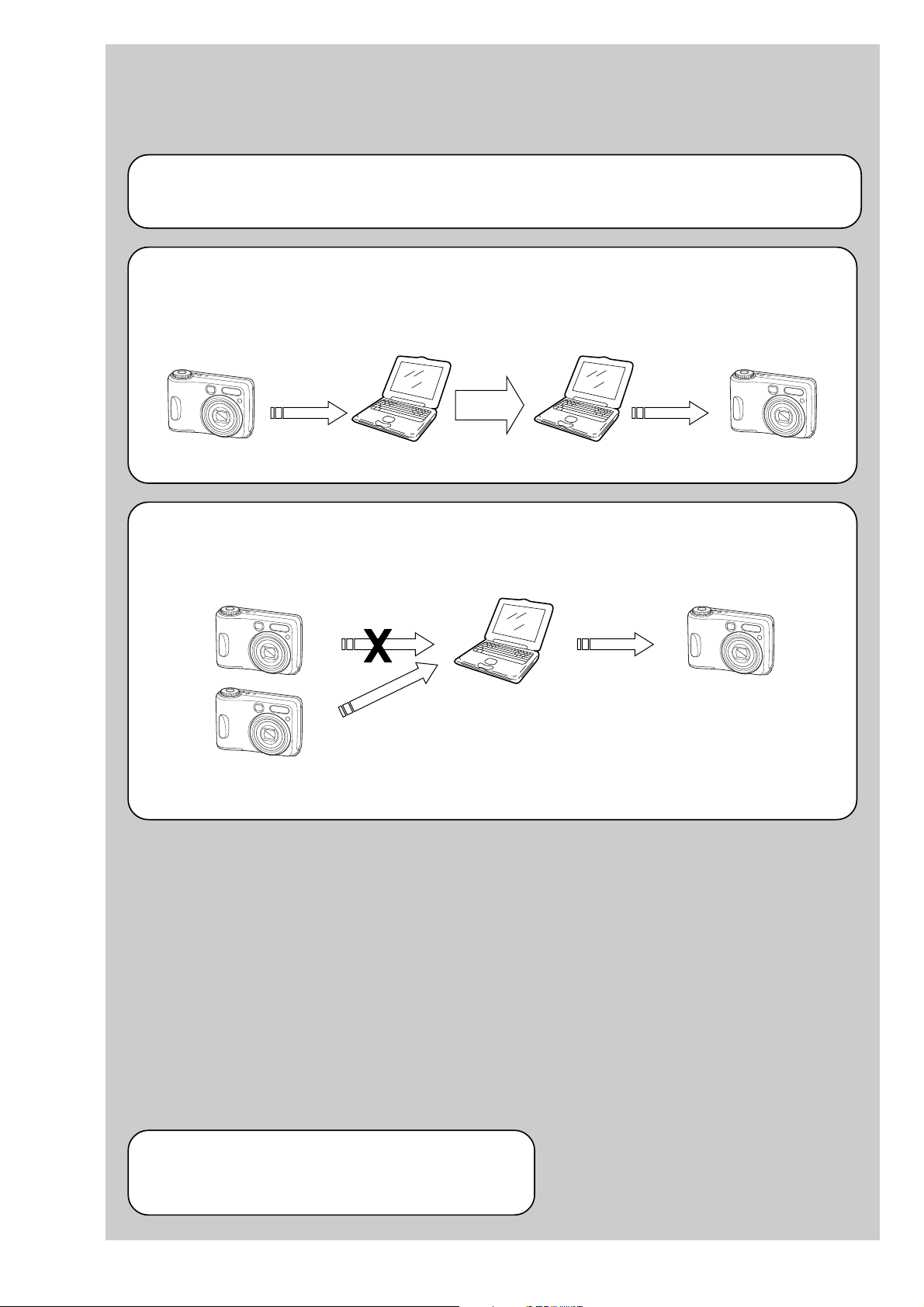
EVR Data Re-writing Procedure When Replacing Board
The data that is stored in the repair board, is not necessarily correct.
Perform either procedure 1 or procedure 2 when replacing board.
Procedure 1
Save the EVR data of the machine in which a board is going to be replaced. Download the saved data after a
board is replaced.
SECTION 6
ADJUSTMENTS
(Machine before starting repair)
Save the EVR data
to a personal computer.
Procedure 2
When the data cannot be saved due to defective flash memory, or when the flash memory cannot be removed or
installed, save the data from the same model of the same destination, and download it.
(Machine to be repaired)
PC
Save the data.
PC
Download the saved
data to a machine.
Download the data.
(Machine after a board is replaced)
(Machine to be repaired)PC
(The same model of the same destination)
After the EVR data is saved and downloaded, check the
respective items of the EVR data.
(Refer to page 6-3 for the items to be checked.)
DSC-S60/S80/S90/ST80
6-1
Method for Copying or Erasing the Data in Internal Memory
The data can be copied/erased by the operations on the Setup screen. (When erasing the data, execute formatting the
internal memory.)
Note 1: When replacing the SY-126 board, erase the data in internal memory of the board before replacement.
Note 2: When replacing the SY-126 board or the IC301 on the SY-126 board, execute formatting and initialize the
internal memory after replacement.
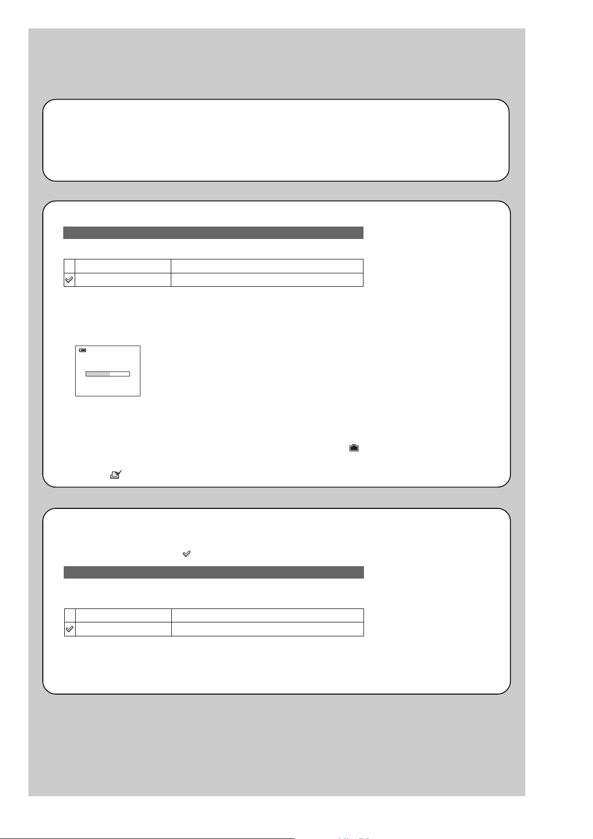
Method for copying the data in internal memory
Copy
Copies all images in the internal memory to a “Memory Stick”.
OK
Cancel
1 Insert a “Memory Stick ” having 32 MB or larger capacity.
2 Select [OK] with v on the control button, then press z.
The message “All data in internal memory will be copied Ready?” appears.
3 Select [OK] with v, then press z.
Copying starts.
Copying
102_COPY
See the following procedure.
Cancels the copying.
•Use batteries with enough capacity or the AC Adaptor (not supplied). If you attempt to copy image files
using batteries with little remaining charge, the batteries may run out, causing copying to fail or possibly
corrupting the data.
•You cannot copy individual images.
•The original images in the internal memory are retained even after copying. To delete the contents of the
internal memory, remove the “Memory Stick” after copying, then execute the [Format] command in
Internal Memory Tool.
•You cannot select a folder copied on a “Memory Stick”.
•The setting of (Print order) marks is not copied even when you copy data.
Method for formatting the internal memory
This item does not appear when a “Memory Stick” is inserted in the camera.
The default se ttings are marked with .
Format
Formats the internal memory.
Note that formatting irrevocably erases all data in the internal memo ry, including even protected images.
OK
Cancel
1 Select [OK] with v on the control button, then press z.
The message “All data in intern al mem or y will be eras ed Ready ?” ap pears .
2 Select [OK] with v, the n pr es s z.
The format is complete.
See the following procedure.
Cancels the formatting.
DSC-S60/S80/S90/ST80
6-2
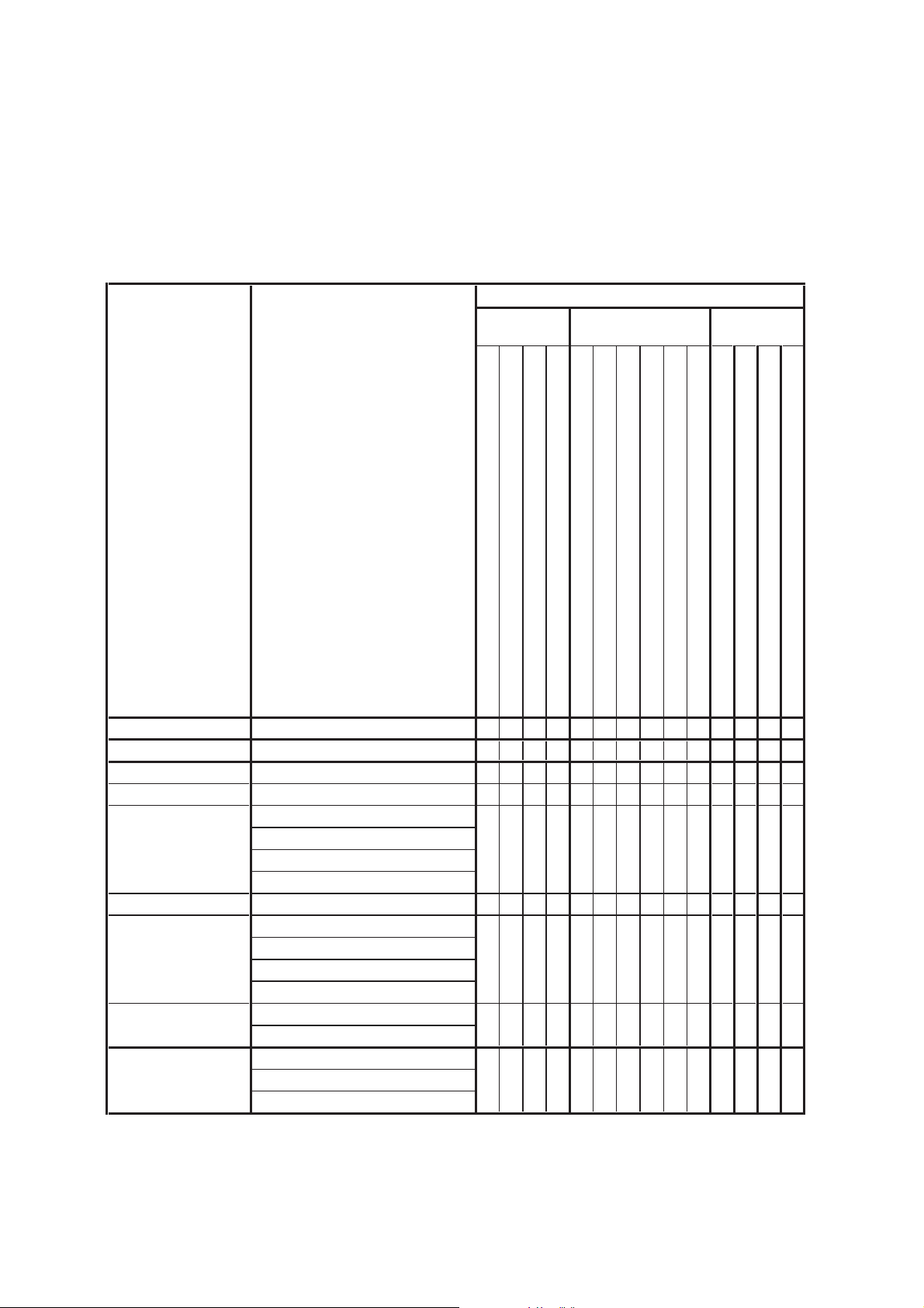
1-1. Adjusting items when replacing main parts and boards
When replacing main parts and boards, adjust the items indicated by z in the following table.
Note 1: The automatic Adjustment Program does not support the “Initialization of data”. Perform it manually.
Note 2: Use the AWB Adjustment Program (S60S80ST80S90AwbAdjustment.exe).
Note 3: When replacing the SY-126 board, erase the data in internal memory of the board before replacement.
Note 4: When replacing the SY -126 board or the IC301 on the SY-126 board, execute formatting and initialize the internal memory after
replacement.
Replaced parts
Block Mounted parts Board
replacement replacement replacement
Adjusting item Adjustment
(Note 1) Initialization of data
VIDEO adjustment Video output level adj.
CAMERA adjustment 1 Flange back adj.
CAMERA adjustment 2 Flange back check
F No. compensation
CAMERA adjustment 3
(Note 2) AWB 3200K-5800K standard data input
CAMERA adjustment 4
CAMERA adjustment 5
LCD adjustment
Measure gain adj.
Mechanical shutter adj.
Light value adj.
Color reproduction adj. & check
CCD linearity check
CCD white defect compensation check
CCD black defect compensation check
Strobe adj.
Auto focus illumination check
COM AC adj.
V-COM adj.
White Balance adj.
LCD unit
Back light unit
(CCD imager)
(Timing gen., CCD signal process)
(AF illumination LED)
(Camera DSP)
(Video amp.)
(32M AND flash) (Note 4)
LCD901
D901
IC001
IC101
D002
IC101
IC103
IC301
(COMPLETE)
(COMPLETE)
(COMPLETE)
(COMPLETE) (Note 3, 4)
Lens block
Flash unit
LCD block
LCD block
CD-573 board
CH-169 board
ST-122 board
SY-126 board
SY-126 board
SY-126 board
CD-573 board
CH-169 board
ST-122 board
SY-126 board
z
zz z
zz zz
zz zz
z
zz
zzz
zzz zzz
z
z
zz z zz
zz z
zz
zz
z
z
zzz
DSC-S60/S80/S90/ST80
Table 6-1-1
6-3
6-1. CAMERA SECTION ADJUSTMENTS
1-1. PREPARATIONS BEFORE ADJUSTMENTS
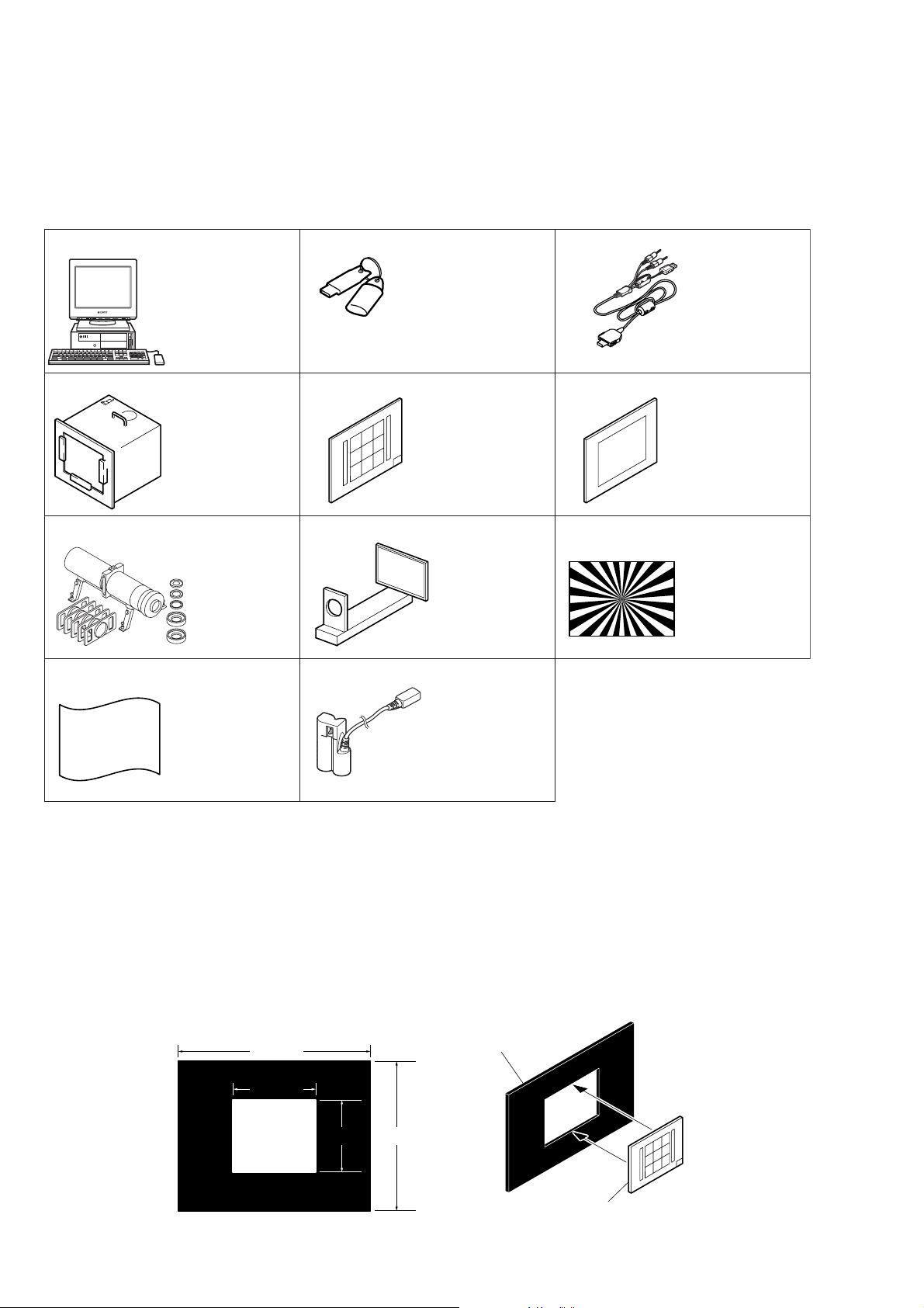
1-1-1. List of Service Tools
• Oscilloscope • Color monitor • AC power adapter
J-1
J-4
J-7
J-10
Personal computer
(Note 1)
Pattern box PTB-450
J-6082-200-A
or
Small pattern box
PTB-1450
J-6082-557-A
Minipattern box
J-6082-353-B
J-2
HASP key and application
for adjustment (SEUS)
Contact our service headquater of each area
how to get the application for adjustment
(SEUS) and HASP key.
J-5
9 colors chart (Note 2)
For PTB-1450:
J-6082-562-A
J-8
Flange back
adjustment jig
J-6082-563-A
J-10
J-3
USB, AV cable for
multi-use terminal
1-830-345-11
J-6
Clear chart
For PTB-450:
J-6080-621-A
For PTB-1450:
J-6082-560-A
J-9
Siemens star chart
J-6080-875-A
Back ground paper
J-2501-130-A
DK-2AA
1-830-351-11
Fig. 6-1-1
Note1: Personal computer
OS: Windows98/98SE/Me/2000/XP Home/XP Pro
RAM: 256MB or more recommended
USB: 2.0 recommended (also compatible with 1.1)
Two connectors are required.
Note2: In using the 9 colors chart on the pattern box PTB-450, adjust the chart size through the procedure shown below so that it
matches to the pattern box PTB-450.
1) Prepare a woody board A of the thickness 5 mm, and paint it mat-black.
2) Fit the 9 colors chart in the woody board A, and secure the chart with a black tape, etc. to shield the light.
Connection cord
woody boad A
360 mm
155 mm
135 mm
280 mm
woody boad A
DSC-S60/S80/S90/ST80
9 colors chart
Fig. 6-1-2
6-4
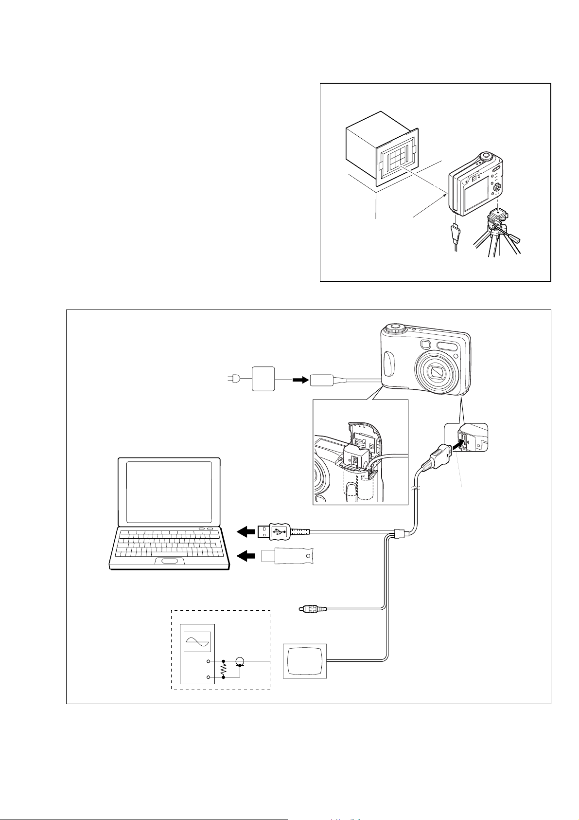
1-1-2. Preparations
PC (The SEUS must be installed in the PC.)
OS: Windows 98/98SE/Me/2000/XP
RAM: 256MB or more recommended
USB: 2.0 recommended (also compatible with 1.1)
Two connectors are required.
AC IN
AC power adaptor
To USB connector
HASP Key
To USB connector
Audio (Black)
Video (yellow)
Video system Adjustment
Osilloscope
Terminated
75 Ω
Color monitor
Insert the connection cord
DK-2AA (1-830-351-11).
To Multi connector
USB, A/V cable
for multi-use terminal
(1-830-345-11)
1) Connect the equipment for adjustments according to Fig. 6-1-4.
2) Start up the application for adjustment (SEUS).
Pattern box
L
Front of the lens
L = About 11 cm
Fig. 6-1-3
DSC-S60/S80/S90/ST80
Fig. 6-1-4
6-5
1-1-3. Precautions
1. Setting the Switch
Unless otherwise specified, set the switches as follows and perform adjustments.
1. Mode Dial .......................................... P (Program auto)
2. ZOOM button..................................... WIDE end
3. Video Out (SET UP setting) .............. NTSC
4. Digital Zoom (SET UP setting) ......... Off
5. EV (Menu items) ............................... 0EV
6. Focus (Menu items) ........................... Multi AF
7. WB (Menu items) .............................. Auto
8. ISO (Menu items) .............................. Auto
9. Flash Level (Menu items) .................. Normal
10. P.Effect (Menu items) ........................ Off
11. Saturation (Menu items) .................... Normal
12. Contrast (Menu items) ....................... Normal
13. Sharpness (Menu items) .................... Normal
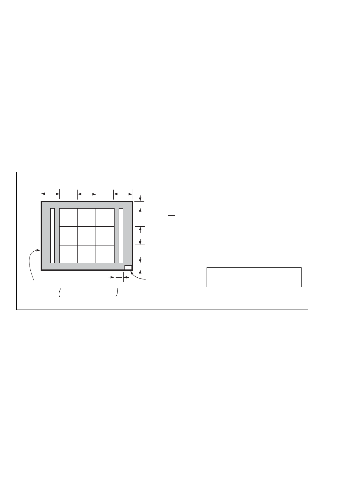
9 colors chart (Standard picture frame)
A
Green
Cyan
C14
Effective picture frame
LCD screen or under scan
Fig. a
monitor TV picture
B
Yellow
White
Blue
W14
Red
Magenta
A
A
2
2. Subjects
1) 9 colors chart (Standard picture frame).
When performing adjustments using the 9 colors chart, adjust
the picture frame as shown in Fig. 6-1-5. (Standard picture
frame)
2) Clear chart (Standard picture frame)
Remove the 9 colors chart from the pattern box and insert a
clear chart in its place. (Do not perform zoom operations during this time)
C
B
C
A = B
C =
C14 : Filter for AWB 5800K adjustment
Transparent window
Fig. 6-1-5
B
3
Adjust the camera position and direction
to obtain the LCD screen or the monitor
TV display shown in Fig. a.
DSC-S60/S80/S90/ST80
6-6
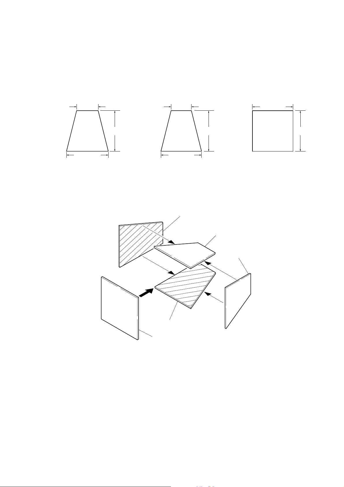
3. Preparing the Flash Adjustment Box
A dark room is required to provide an accurate flash adjustment.
If it is not available, prepare the flash adjustment box as given
below;
1) Provide woody board A, B and C of 15 mm thickness.
woody board A (2)
400 mm
513 mm 513 mm 700 mm
woody board B (2)
Fig. 6-1-6
2) Apply black mat paint to one side of woody board A and B.
3) Attach background paper (J-2501-130-A) to woody board C.
4) Assemble so that the black sides and the background paper
side of woody board A, B and C are internal. (Fig. 6-1-7)
370 mm
700 mm730 mm
woody board A
woody board C (1)
700 mm
woody board B
woody board A
DSC-S60/S80/S90/ST80
woody board B
woody board C
Fig. 6-1-7
6-7
1-1-4. Using Method of SEUS
The application for adjustment (SEUS) is used to change the coefficient for calculating the signal processing or EVR data. The SEUS
performs two-way communication between PC and set through
the USB terminal. The two-way communication result data can be
written to the nonvolatile memory.
1. Connection
1) Connect the HASP key to the USB terminal of the PC.
2) Connect the PC and set with the USB cable.
3) Confirm that the set starts in the USB mode.
4) Start the SEUS on the PC.
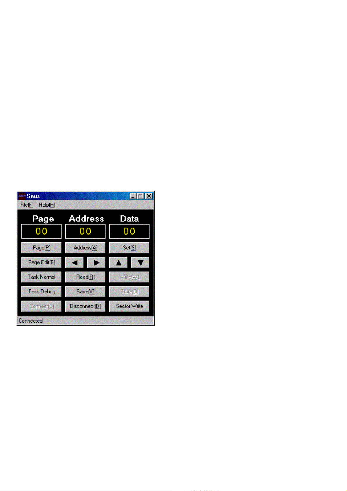
5) Click [Connect] on the SEUS screen. If the connection is normal, the SEUS screen will be as shown in Fig. 6-1-8, indicating the
“connected” state.
Note: The SEUS will go in
turned off (for instance, by resetting the set). In such a
case, click [Connect] on the SEUS screen to restore
the
“connected” state.
“disconnect" state, if the set is
2. Operation
• Page change
To change the page, click [Page] on the SEUS screen and enter
the page to be changed. The page is displayed in hexadecimal
notation.
• Address change
To change the address, click [Address] on the SEUS screen and
enter the address to be changed. The address is displayed in
hexadecimal notation.
• Data change
To change the data, click [Set] on the SEUS screen and enter
the data. The data is displayed in hexadecimal notation.
This operation does not write the data to the nonv olatile memory .
• Data saving
To write the all changed data to the nonvolatile memory, click
[Save] on the SEUS screen and wait for more than 3 sec.
• Data reading
The data displayed on the SEUS screen are the data values at
the time when the pages and addresses were set, and they are
not updated automatically. To check the data change, click
[Read] on the SEUS screen and update the displayed data.
1-1-5. Precaution on Use of SEUS
Wrong SEUS operation could clear correct adjustment data. To
prevent the data clear by mistake, it is recommended to save all
adjustment data by clicking [Page Edit] on the SEUS screen before starting the adjustment.
Fig. 6-1-8
Saving Method:
1) Click [Page Edit] on the SEUS screen to display the SEUS
PAGE EDIT screen.
2) Click [Page], and enter the page number to be saved.
3) Click [Page] to read the data to be saved from the camera.
4) Click [File] and save the data to PC.
Loading Method:
1) Select page: 00, address: 01 and set data: 01.
2) Click [Page Edit] on the SEUS screen to display the SEUS
PAGE EDIT screen.
3) Click [File] and load the data from PC.
4) Click [Write] on the SEUS PAGE EDIT screen.
5) Click [Close] to close the SEUS PAGE EDIT screen.
6) Click [Save] on the SEUS screen.
7) Wait for more than 3 sec.
8) Select page: 80, address: 30, and check that the data is “00”.
9) Select page: 00, address: 01 and set data: 00.
DSC-S60/S80/S90/ST80
6-8
 Loading...