

Page 1

DIGITAL VIDEO HYBRID RECORDER
DNW-A100/A100P
DNW-A50/A50P
DNW-A45/A45P
OPERATION MANUAL
1st Edition (Revised 4)
Serial No. 10001 and Higher
[English]
Page 2
WARNING
For the customers in the United Kingdom
To prevent fire or shock hazard, do
not expose the unit to rain or
moisture.
To avoid electrical shock, do not
open the cabinet. Refer servicing to
qualified personnel only.
This symbol is intended to alert the
user to the presence of important
operating and maintenance (servicing)
instructions in the literature
accompanying the appliance.
WARNING: Using this unit at a voltage other than
120V may require the use of a different
line cord or attachment plug, or both. To
reduce the risk of fire or electric shock,
refer servicing to qualified service
personnel.
For the customers in the USA
This equipment has been tested and found to comply
with the limits for a Class A digital device, pursuant to
Part 15 of the FCC Rules. These limits are designed
to provide reasonable protection against harmful
interference when the equipment is operated in a
commercial environment. This equipment generates,
uses, and can radiate radio frequency energy and, if
not installed and used in accordance with the
instruction manual, may cause harmful interference
to radio communications. Operation of this
equipment in a residential area is likely to cause
harmful interference in which case the user will be
required to correct the interference at his own
expense.
You are cautioned that any changes or modifications
not expressly approved in this manual could void
your authority to operate this equipment.
WARNING
THIS APPARATUS MUST BE EARTHED
IMPORTANT
The wires in this mains lead are coloured in
accordance with the following code:
Green-and-yellow: Earth
Blue: Neutral
Brown: Live
As the colours of the wires in the mains lead of this
apparatus may not correspond with the coloured
markings identifying the terminals in your plug
proceed as follows:
The wire which is coloured green-and-yellow must be
connected to the terminal in the plug which is marked
by the letter E or by the safety earth symbol Y or
coloured green or green-and-yellow.
The wire which is coloured blue must be connected
to the terminal which is marked with the letter N or
coloured black.
The wire which is coloured brown must be connected
to the terminal which is marked with the letter L or
coloured red.
For the customers in Europe
This product with the CE marking complies with both
the EMC Directive (89/336/EEC) and the Low
Voltage Directive (73/23/EEC) issued by the
Commission of the European Community.
Compliance with these directives implies conformity
to the following European standards:
• EN60065: Product Safety
• EN55103-1: Electromagnetic Interference
(Emission)
• EN55103-2: Electromagnetic Susceptibility
(Immunity)
This product is intended for use in the following
Electromagnetic Environment(s):
E1 (residential), E2 (commercial and light industrial),
E3 (urban outdoors) and E4 (controlled EMC
environment, ex. TV studio).
The shielded interface cable recommended in this
manual must be used with this equipment in order to
comply with the limits for a digital device pursuant to
Subpart B of Part 15 of FCC Rules.
Page 3
Table of Contents
Chapter 1
Overview
Chapter 2
Location and Function of
Parts
Chapter 3
Preparations
1-1 Overview ......................................................................................... 1-1
1-2 Example System Configurations................................................... 1-4
2-1 Control Panels ................................................................................ 2-1
2-1-1 Upper Control Panel............................................................... 2-2
2-1-2 Lower Control Panel .............................................................. 2-8
2-1-3 Subsidiary Control Panel ..................................................... 2-19
2-2 Connector Panel .......................................................................... 2-22
3-1 Connections to External Devices................................................... 3-1
3-2 Reference Signals for Video Output and Servo System.............. 3-3
3-2-1 External Sync Signal for the Internal Reference Video Signal
Generator................................................................................ 3-3
3-2-2 Reference Signal for the Servo System.................................. 3-4
3-2-3 Connecting Reference Signals ............................................... 3-5
3-3 Setup ................................................................................................ 3-7
3-4 Superimposed Character Information ......................................... 3-8
3-5 Cassettes ........................................................................................ 3-10
3-5-1 Cassette Types...................................................................... 3-10
3-5-2 Inserting and Ejecting Cassettes .......................................... 3-10
3-5-3 Preventing Accidental Erasure of Recordings ..................... 3-11
Chapter 4
Recording and Playback
Chapter 5
Editing Using the Built-in
Hard Disk
(Continued)
4-1 Recording ........................................................................................ 4-1
4-1-1 Preparations for Recording .................................................... 4-1
4-1-2 Recording Time Code and User Bit Values........................... 4-2
4-1-3 Recording Procedure.............................................................. 4-5
4-2 Playback .......................................................................................... 4-6
4-2-1 Preparations for Playback ...................................................... 4-6
4-2-2 Playback/Feed Play Procedures ............................................. 4-8
5-1 Overview ......................................................................................... 5-1
5-2 Basic Editing Operations ............................................................... 5-2
5-2-1 Control Modes........................................................................ 5-2
5-2-2 Sequence of Editing Operations............................................. 5-2
5-2-3 Switch Settings....................................................................... 5-3
5-2-4 Specifying Devices ................................................................ 5-4
5-2-5 Selecting the Editing Mode.................................................... 5-4
5-2-6 Setting Edit Points.................................................................. 5-7
5-2-7 Modifying and Deleting Edit Points ...................................... 5-8
5-2-8 Cue-up to Edit Points and Preroll .......................................... 5-9
5-2-9 Preview................................................................................. 5-10
5-2-10 Carrying Out Editing .......................................................... 5-11
5-2-11 Undoing an Editing Operation............................................ 5-12
5-2-12 Standalone Editing.............................................................. 5-13
Table of Contents 1
Page 4

Table of Contents
Chapter 5
Editing Using the Built-in
Hard Disk
(continued)
Chapter 6
Editing Without Using the
Built-in Hard Disk (TwoVTR Editing)
5-3 Multi-Event Editing ..................................................................... 5-14
5-3-1 Saving Event Specifications................................................. 5-14
5-3-2 Modifying and Deleting Events........................................... 5-15
5-3-3 Preview ................................................................................ 5-15
5-3-4 Carrying Out Multi-Event Editing....................................... 5-15
5-4 Special Nonlinear Editing Operations........................................ 5-17
5-4-1 Modifying Edit Points After Carrying Out Editing ............. 5-17
5-4-2 Deleting an Arbitrary Segment After Carrying Out Editing 5-18
5-4-3 Reordering Events After Carrying Out Editing ................... 5-18
5-4-4 Simultaneous Recording on Tape and the Hard Disk.......... 5-19
5-5 Summary of Editing operations .................................................. 5-20
5-6 Points to Remember About Editing............................................ 5-21
5-6-1 Automatic Previews in Tape Editing ................................... 5-21
5-6-2 Tape Editing Precision......................................................... 5-21
5-6-3 Preroll In Editing From Hard Disk to Tape ......................... 5-21
5-6-4 Limitations When Editing With MASTER as Player .......... 5-22
5-6-5 Control of the Audio and Video Recording Levels ............. 5-22
6-1 Automatic Editing .......................................................................... 6-1
6-1-1 Overview................................................................................ 6-1
6-1-2 Switch Settings....................................................................... 6-2
6-1-3 Setting Edit Points.................................................................. 6-3
6-1-4 Modifying and Deleting Edit Points ...................................... 6-4
6-1-5 Cue-up to Edit Points and Preroll .......................................... 6-5
6-1-6 Preview................................................................................... 6-6
6-1-7 Carrying Out Automatic Editing............................................ 6-7
6-2 Special Automatic Editing Methods ............................................. 6-9
6-2-1 Quick Editing ......................................................................... 6-9
6-2-2 Continuous Editing ................................................................ 6-9
6-2-3 Standalone Editing............................................................... 6-10
Chapter 7
Menu System
Chapter 8
Maintenance and
Inspection
Appendix
2 Table of Contents
7-1 Menu System Configuration ......................................................... 7-1
7-2 Basic Menu...................................................................................... 7-1
7-2-1 Items in the Basic Menu......................................................... 7-1
7-2-2 Basic Menu Operations.......................................................... 7-4
7-3 Extended Menu............................................................................... 7-9
7-3-1 Items in the Extended Menu .................................................. 7-9
7-3-2 Extended Menu Operations.................................................. 7-24
7-4 Disk File Management Menu ...................................................... 7-25
7-4-1 Items in the Disk File Management Menu........................... 7-25
7-4-2 Operations in the Disk File Management Menu.................. 7-26
8-1 Removing a Cassette When Tape Slack Occurs .......................... 8-1
8-2 Head Cleaning ................................................................................ 8-1
8-3 Starting the Hard Disk Drive Under Cold Conditions ............... 8-1
8-4 Moisture Condensation.................................................................. 8-2
8-5 Digital Hours Meter ....................................................................... 8-3
Specifications......................................................................................... A-1
Page 5
1-1 Overview
Chapter 1 Overview
The DNW-A100/A100P/A50/A50P/A45/A45P (also
referred to simply as the unit in this manual) is a
hybrid recorder, integrating a hard disk and VTR with
editing functions, based on the Betacam SX format.
The following table outlines the differences in the
functions of the DNW-A100/A100P, DNW-A50/
A50P, and DNW-A45/A45P.
Model Hard disk (dual
DNWA100/
A100P
DNWA50/
A50P
DNWA45/
A45P
channel)
Built-in: 2 units (1
pair); SCSI connection
for external expansion
units
Data capacity: 9 GB/disk
Continuous recording
time: about 88 minutes
(DNW-A100) or 92
minutes (DNW-A100P)
per disk pair
Data capacity: 9 GB/disk
Continuous recording
time: about 88 minutes
(DNW-A50) or 92
minutes (DNW-A50P)
per disk pair
Data capacity: 4 GB/disk
Continuous recording
time: about 41 minutes
(DNW-A45) or 43
minutes (DNW-A45P)
per disk pair
Highspeed
transfer
function
(FEED
button)
Yes Yes (but
No No
No No
SDDI I/O
connectors
input is an
option)
Betacam SX format
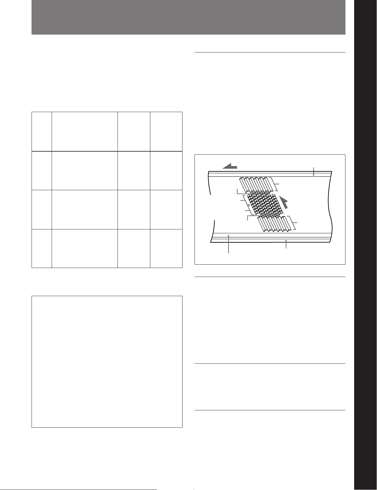
The Betacam SX format was developed as a digital
version of the Betacam SP format, and is a digital VTR
format supporting nonlinear editing systems and server
systems. Compared with analog Betacam, the
Betacam SX format reduces the tape speed to
approximately one-half. The drum rotates at 75
revolutions per second, recording two frames of video
data and four channels of digital audio in ten diagonal
tracks. The longitudinal control and time code tracks
are the same as in the analog Betacam format.
Tape transport direction
System data
Audio channels
1 to 4
Audio channels
1 to 4
System data
Control (CTL) track
Time code track
Auxiliary track
Video
Head
direction
Video
Chapter 1 Overview
For detailed specifications, see “Specifications” in the
Appendix.
There are some functional and operational
differences between units with a version number of
2.00 or later and units with a version number before
2.00. When necessary, this manual will provide
separate explanations for version 2.00 or later units
and units before version 2.00.
Control panel differences
Units before version 2.00 have AUDIO INPUT/
MONITOR SELECT buttons on the upper control
panel. On version 2.00 or later units, these buttons
are the AUDIO INPUT/MIXING/MONITOR
SELECT buttons (see figure on page 2-3). Version
2.00 or later units also have a MIXING indicator to
the left of the buttons. This indicator is not found on
units before version 2.00.
The following are some of the features of the system.
Head configuration
In addition to digital recording and playback heads for
Betacam SX, the unit also has analog playback heads
for Betacam SP. There are sixteen digital playback
heads, allowing high-speed data transfer at four times
normal speed (DNW-A100/A100P only), and CONFI
playback (simultaneous playback) for checking
recording.
Digital signal processing
This unit processes digital signals conforming to 4:2:2
component digital D-1 format.
High image quality, high audio quality,
high reliability
Even with a low data rate, recording and playback with
high image quality and high audio quality is achieved.
The unit also has a powerful error-correcting system.
Chapter 1 Overview 1-1
Page 6
1-1 Overview
Chapter 1 Overview
Data compression by interframe encoding
This is the first VTR to perform data compression by
MPEG-2 interframe encoding conforming to 4:2:2
Profile @ Main level. The data rate is reduced by a
factor of 10.
Playback compatibility with Betacam/
Betacam SP
This unit can play tapes recorded in Betacam/Betacam
SP format. Simultaneously with this playback
operation, you can copy the material to the hard disk
for nonlinear editing. This makes for efficient use of
existing material in Betacam/Betacam SP format.
Wide range of input and output signals
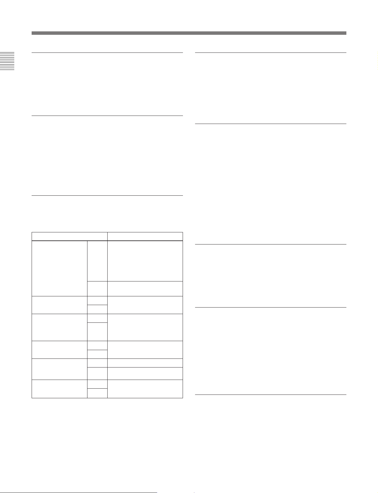
You can use the following wide range of input and
output signals.
Signals Standard or option
Analog video Input Optionally either of
composite (BKDW-505 for
DNW-A100/A50/A45 or
BKDW-506 for DNW-A100P/
A50P/A45P) or component
(BKNW-104)
Output Fitted as standard
Analog audio
(4 channels)
AES/EBU digital
audio
a)
video/audio Input Fitted as standard
SDI
b)
SDDI
video/audio
(DNW-A100/A100P
only)
Time code Input Fitted as standard
a) Serial Digital Interface
b) Serial Digital Data Interface
Input Fitted as standard
Output
Input Available as option (BKNWOutput
Output
Input Option (BKNW-103)
Output Fitted as standard
Output
(composite and component)
105) to replace the standard
analog audio inputs and
outputs
Powerful editing functions
These include assemble editing using the built-in VTR,
and nonlinear editing using the built-in hard disk. This
unit can also be used as the player for two-unit editing.
Further, by connecting an editor, you can carry out
GUI-based editing.
High-speed data transfer (DNW-A100/
A100P only)
This unit can carry out the following high-speed data
transfers:
•Copying from tape to hard disk at four times normal
speed
•Transfer at four times normal speed to an audio/video
server through the SDDI interface
•High-speed data transfer through the SDDI interface
to an SNG (Satellite News Gathering) system
Monitoring of video and audio is also possible during
high-speed transfers.
Menu-based setup
Initial settings for the unit’s operating condition, the
interfaces with connected equipment, and so forth can
be made by menu operations on the front panel of the
unit.
Wide range of indications
In addition to the LED display which shows the
operating status and current settings of this unit and
connected equipment, a fluorescent display displays
numerical values including time code, user bits, editing
IN and OUT points, editing durations, error messages,
setup menu information, hard disk recorded amounts
and remaining space, and event information.
Selection of external/internal time code
You can record using either an external time code or
the output of the built-in time code generator. You can
also synchronize the built-in time code generator to an
external time code.
1-2 Chapter 1 Overview
Page 7

Connection to external control devices
It is possible to connect a BVE-900/910/2000/9000/
9000P/9100/9100P or other BVE-series editor, a
control and monitoring computer, a BVR-50/50P
remote controller for the built-in digital video
processor, and so forth.
Economy
•You can use a variety of tapes, including low-priced
tapes for UVW-series VTRs and tapes for Betacam
SP or Betacam SX format. Using large cassettes,
recording of 180 minutes or more is possible.
•The design needs minimal maintenance, and requires
no daily maintenance or checks. The drum and other
components have reduced maintenance costs.
Rack mounting
The unit can be mounted in an EIA standard 19-inch
rack.
Chapter 1 Overview
For details of rack mounting, refer to the Maintenance
Manual Part 1.
Chapter 1 Overview 1-3
Page 8
Chapter 1 Overview
1-1 Overview
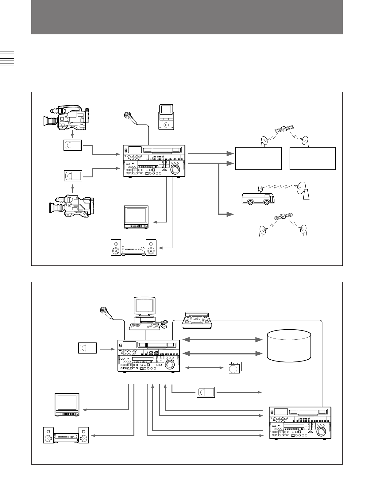
1-2 Example System Configurations
The following conceptual diagrams show examples of
use in an outside broadcast van or local station and
within a broadcasting station.
•Operation in an outside broadcast van or local station
Betacam SX camcorder
Microphone
Digital cassette
Analog cassette
DNW-A100/A100P
Analog
composite
Betacam SP camcorder
Video monitor
Audio monitor
•Operation in a broadcasting station
Portable editor
Analog audio
Digital (SDDI/SDI)
Analog
composite
SNG a) system
Digital modulator
a) SNG: Satellite News Gathering
Digital
demodulator
On-line editor (for cut editing)
Microphone
BVE-series editor
Digital/analog cassette
DNW-A100/A100P
Video monitor
Analog composite
Analog composite/component
Audio monitor
a) You cannot control this unit as a recorder using a BVE-series editor.
a)
Tape control
SDDI
SDI
SCSI
Digital cassette
SDIAnalog audio
Audio/video
server
system
Additional
hard disks
VTR with SDI connectors
or analog VTR
1-4 Chapter 1 Overview
Page 9
2-1 Control Panels
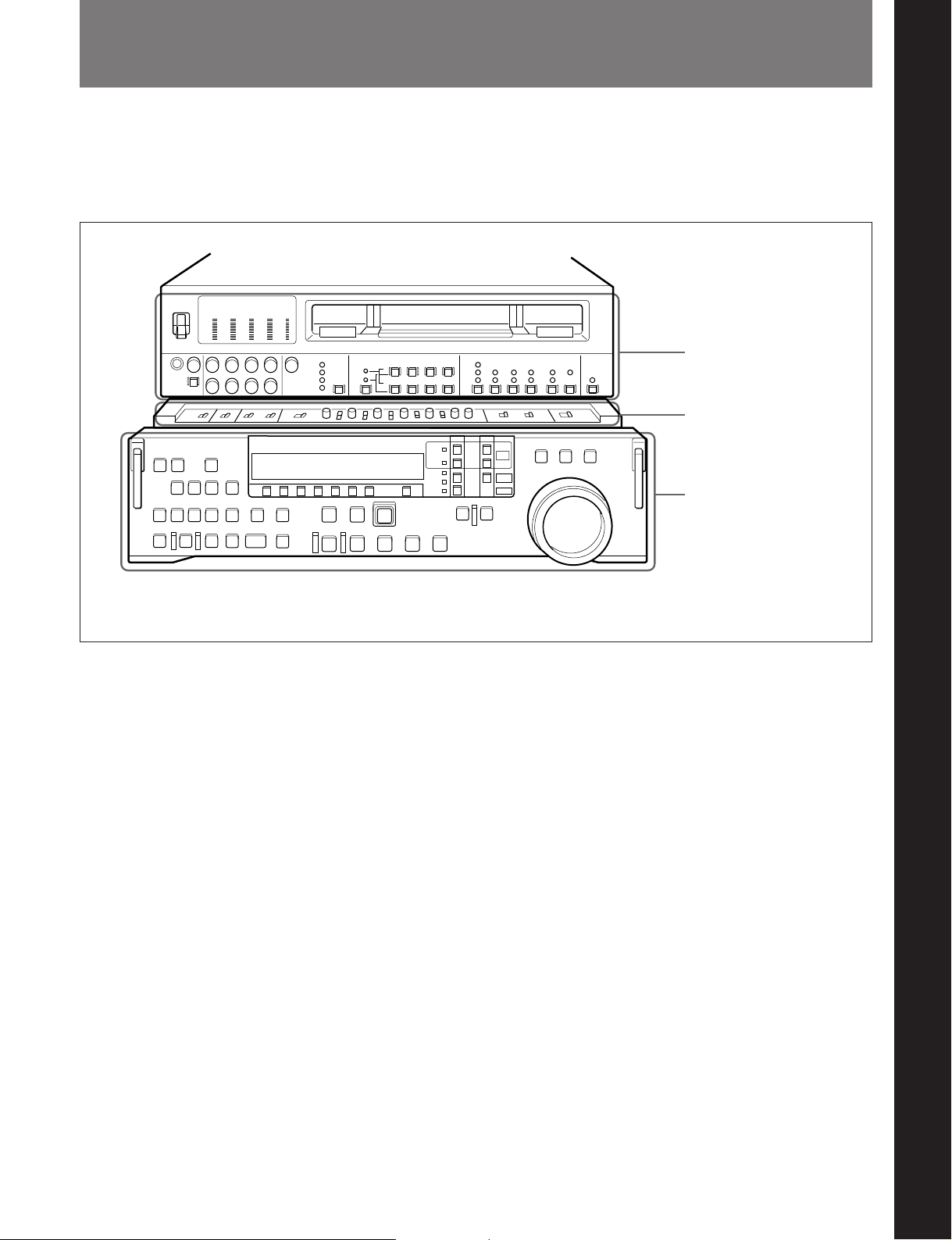
There are three front control panels, as follows:
•Upper control panel
•Subsidiary control panel
•Lower control panel
Chapter 2 Location and Function of Parts
Chapter 2 Location and Function of Parts
Upper control panel
(See page 2-2.)
Subsidiary control panel
(See page 2-19.)
Lower control panel
(See page 2-8.)
To reveal the subsidiary control panel, pull the lower control panel forward.
Chapter 2 Location and Function of Parts 2-1
Page 10
2-1 Control Panels
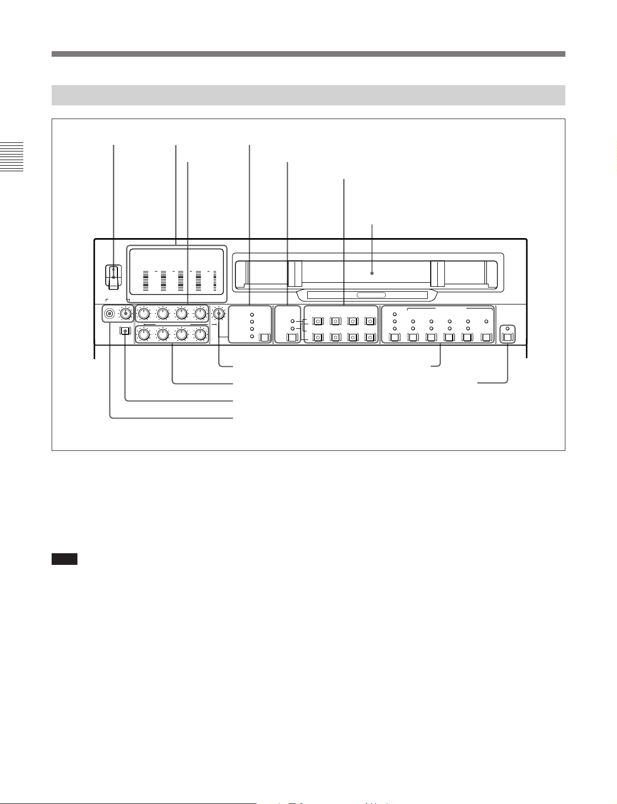
2-1-1 Upper Control Panel
1 POWER
Chapter 2 Location and Function of Parts
POWER
ON
OFF
PHONES
switch
dB
dB
0
0
-10
-10
-20
-20
-30
-30
-40
-40
-80
-80
CH-1 CH-2 CH-3 CH-4 VIDEO
DISPLAY
FULL/FINE
PULL FOR VARIABLE
2 Level meters
3 REC controls
dB
dB
0
0
-10
-10
-20
-30
-40
-80
REC
PB
2
0
-20
-2
-30
-40
-4
-80
4 VIDEO INPUT SELECT switch and indicators
5 Audio selection function selector switch and indicators
6 AUDIO INPUT/MONITOR SELECT buttons
(Before Version 2.00)
AUDIO INPUT/MIXING/MONITOR SELECT
buttons (Version 2.00 or later)
Cassette compartment
ANALOG /
HIGH SPEED
VIDEO INPUT SELECT AUDIO INPUT/MONITOR SELECT
(VIDEO&AUDIO)
COMPONENT
(Y-R,B)
COMPOSITE
SDDI
SDI
INPUT
MONITOR
7 VIDEO control
8 PB controls
CH-1 CH-2 CH-3 CH-4
SDI
L
ANALOG/
AES/EBU
R
AUTO
!¡ Time code setting section
!™ REMOTE/LOCAL switch and indicator
9 DISPLAY FULL/FINE switch
0 PHONES jack and control
DIGITAL
TC
LTC
VITC
TC GENERATOR
FREE
INT
PRESET
EXT
REGEN
DEF
RUN
REC
NDF
RUN
REMOTE
/LOCAL
VITC
ON
9P
1 POWER switch
This powers the unit on and off. When the unit is
powered on, the level meters 2 and the fluorescent
display in the lower control panel light.
To power the unit off, press the side of the POWER
switch marked “OFF”.
2 Level meters
These show the audio levels of channels 1 to 4
1)
(recording levels in recording mode or E-E mode
and
playback level in playback mode) and the video levels
of input composite video signals.
There are two modes for audio level indications:
FULL and FINE, selected by the DISPLAY FULL/
Note
FINE switch 9.
After carrying out operations on this unit using the
hard disk, before powering the unit off be sure to press
the EJECT button (see page 2-17) to close the files on
the hard disk. Powering off the unit with files left
open may result in a loss of system data from the hard
disk.
..........................................................................................................................................................................................................
1) E-E mode: Abbreviation of “Electric-to-Electric mode.”
In this mode, video and audio signals input to the VTR
are output after passing through internal electric circuits,
but not through magnetic conversion circuits such as
heads and tapes. This can be used to check input signals
and for adjusting input signal levels.
2-2 Chapter 2 Location and Function of Parts
Page 11
3 REC (recording level) controls
These adjust individually the recording levels on
channels 1 to 4.
To set the recording level, put the unit in E-E mode,
pull out the control knobs and adjust the level while
watching the audio level meters 2.
When the control knobs are pushed in, the recording
levels return to the preset levels (0 dBm reference level
for an input of +4 dBm), and cannot be adjusted.
These controls do not function in the following cases.
•When SDDI video input is selected.
•When signals recorded on digital tape are being
copied to the hard disk (including recording during
editing operation).
For details of selecting the E-E mode, see the description of
the REC button in the tape/disk transport control section
(see page 2-16) and the PB. EE button in the monitor/menu/
display setting section (see page 2-9).
4 VIDEO INPUT SELECT switch and indicators
When an external device (EXT) is selected as the
player by the device specification buttons (see page 2-
12), this switch selects the video input signal in the
following sequence. (When the player is other than an
external device, this switch and the indicators have no
function.)
SDDI n SDI n COMPONENT or COMPOSITE
(SDDI input is an option for the DNW-A100/A100P.
Only one of the component and composite video input
options can be installed. It is not possible to use the
input of the type which is not installed.)
SDDI (DNW-A100/A100P only): SDDI video signal
input to the SDDI DIGITAL INPUT connector (In
this case the SDDI audio signals are
simultaneously selected.)
SDI: SDI video signal input to the SDI DIGITAL
INPUT connectors
COMPONENT: Analog component video signal
input to the COMPONENT VIDEO INPUT
connectors.
COMPOSITE: Analog composite video signal
input to the COMPOSITE VIDEO INPUT
connectors.
The indicators light according to the selection. If there
is a fault on the selected input (such as no input
signal), the indicator flashes.
Note
When you have used the device specification buttons
(see page 2-12) to set this switch to SDDI with EXT
selected as the player and TAPE selected as the
recorder, the REC INHIBIT indicator lights
automatically and recording on tape is prohibited.
Recording on the hard disk is not prohibited.
Using a video test signal
Holding down the VIDEO INPUT SELECT switch for
at least three seconds lights all four of the indicators,
and causes an internal signal generator to produce a
video test signal.
To stop the production of the video test signal, press
this switch and release within three seconds.
When the VIDEO INPUT SELECT switch is set to
SDDI, you cannot use the video test signal.
It is only possible to use this function when extended menu
item 710 is set to select a video test signal.
5 Audio selection function selector switch and
indicators
(Before Version 2.00)
Pressing this switch lights the INPUT indicator and
MONITOR indicator alternately, and selects the
function of the AUDIO INPUT/MONITOR SELECT
buttons.
When the INPUT indicator is lit: You can use the
AUDIO INPUT/MONITOR SELECT buttons to
select the audio input signals.
When the MONITOR indicator is lit: You can use
the AUDIO INPUT/MONITOR SELECT buttons
to select the audio output channels.
(Version 2.00 or later)
Pressing this switch lights the INPUT indicator,
MONITOR indicator and MIXING indicator
cyclically, and selects the function of the AUDIO
INPUT/MIXING/MONITOR SELECT buttons.
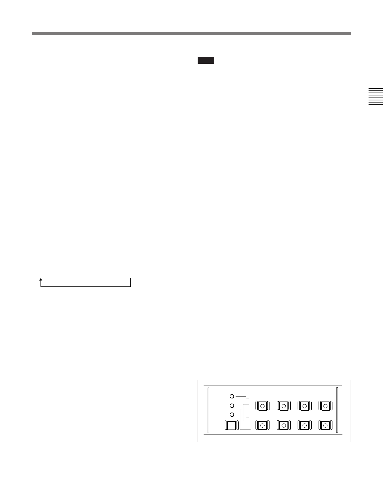
AUDIO INPUT/MIXING/MONITOR SELECT
MIXING
INPUT
MONITOR
CH-1 CH-2 CH-3 CH-4
PLAYER
SDI
L
RECORDER
ANALOG/
AES/EBU
R
Chapter 2 Location and Function of Parts
Chapter 2 Location and Function of Parts 2-3
Page 12

2-1 Control Panels
When the INPUT indicator is lit: You can use the
AUDIO INPUT/MIXING/MONITOR SELECT
buttons to select the audio input signals.
When the MONITOR indicator is lit: You can use
the AUDIO INPUT/MIXING/MONITOR
SELECT buttons to select the audio output
Chapter 2 Location and Function of Parts
channels.
When the MIXING indicator is lit: You can use the
AUDIO INPUT/MIXING/MONITOR SELECT
buttons to select the audio channels for recording
from the player to the recorder selected with the
device specification buttons (see page 2-12). It is
possible to mix the audio signals from two player
audio channels and record the mixed signal to a
recorder audio channel.
Using an audio test signal
(Before Version 2.00)
Holding down the audio selection function selector
switch for at least 3 seconds lights both of the INPUT
and MONITOR indicators, and causes an internal
signal generator to produce an audio test signal.
To stop the production of the audio test signal, press
this switch and release within 3 seconds.
(Version 2.00 or later)
Press the audio selection function selector switch
several times until the INPUT indicator lights. Then
press the CH-1 button in the SDI row or the
ANALOG/AES/EBU row and keep it pressed for 3
seconds or longer. When you release the button, all of
the AUDIO INPUT/MIXING/MONITOR SELECT
buttons light and an internal signal generator produces
an audio test signal.
During production of the audio test signal, the INPUT
indicator remains lit even if you use the audio selection
function selector switch to select MIX or MONITOR.
To stop the production of the audio test signal, press
the audio selection function selector switch so that
only the INPUT indicator is lit. Then press any of the
AUDIO INPUT/MIXING/MONITOR SELECT
buttons, releasing the button within 3 seconds.
When the VIDEO INPUT SELECT switch is set to
SDDI, you cannot use the audio test signal.
It is only possible to use this function when extended menu
item 808 is set to select an audio test signal.
6 AUDIO INPUT/MONITOR SELECT buttons
(Before Version 2.00)
AUDIO INPUT/MIXING/MONITOR SELECT
buttons (Version 2.00 or later)
The function of these buttons depends on the setting of
the audio selection function selector switch as follows.
When the INPUT indicator is lit
For each channel, press the button in the SDI row or
the ANALOG/AES/EBU row.
The pressed button lights and the corresponding audio
input signal is selected.
However, when the video input signals selected with
the VIDEO INPUT SELECT switch are SDDI, the
audio input signals for all channels are also set to
SDDI.
Note
Only one of the ANALOG inputs and AES/EBU
digital inputs can be installed. The ANALOG inputs
are installed as standard.
When the MONITOR indicator is lit
Press the buttons in the L and R rows to select the
audio signal channels (channels 1 to 4, identified as
CH-1 to CH-4) output from the MONITOR OUTPUT
L and MONITOR OUTPUT R connectors.
You can press two or more buttons simultaneously in
each row, turning them on, to monitor an output
produced by mixing the selected channels.
When the MIXING indicator is lit (Version 2.00 or
later)
To select a player channel to record on a recorder
channel, press one of the buttons (CH-1 to CH-4) in
the PLAYER side row while pressing one of the
buttons (CH-1 to CH-4) in the RECORDER side row.
For example, if you press the CH-2 button in the
PLAYER side row while pressing the CH-1 button in
the RECORDER side row, signals from player channel
2 are recorded in recorder channel 1.
If you press two PLAYER side buttons
simultaneously, signals from the corresponding two
channels are mixed and recorded in the recorder
channel.
2-4 Chapter 2 Location and Function of Parts
Page 13

Note
Before selecting signals from two player channels for
recording in one recorder channel, check to be sure
that the emphasis settings (ON or OFF) of the two
player channels are the same. Recording and playback
of mixed signals cannot be carried out correctly if the
emphasis settings are different.
You can check the settings in the channel display
section of the level meters. [EMPH] is displayed for
channels with the emphasis setting on.
The RECORDER side button that was pressed remains
lit after you have finished making the settings. When
you press the lit RECORDER side button, the
PLAYER side buttons that were pressed when you
made the settings light up again. This allows you to
check the settings. To cancel the settings, press the
corresponding button on the RECORDER side while
pressing the button for the same channel on the
PLAYER side.
Note
The channel copy and mixing settings described above
are disabled during the following types of editing.
•Automatic editing in feed mode (see page 5-11) when
TAPE has been selected as the player and MASTER
or PROGRAM has been selected as the recorder.
•Automatic editing when MASTER or PROGRAM
has been selected as the player and PROGRAM has
been selected as the recorder.
Adjusting the recording level when the
MIXING indicator is lit
Adjust by rotating the REC knob for the PLAYER side
channel while viewing the level meter for the
RECORDER side channel.
For example, when recording PLAYER side channel 1
signals in RECODER side channel 2, rotate the CH-1
REC knob while viewing the level meter for CH-2.
7 VIDEO control
This adjusts the level of a composite video signal input
to the COMPOSITE VIDEO INPUT connectors.
Pull out the control knob and adjust the level. When
the control knob is pushed in, the automatic gain
control (AGC) function comes into effect.
8 PB (playback level) controls
These adjust individually the playback levels on
channels 1 to 4.
During playback, pull out the control knobs and adjust
the level while monitoring the audio level indication
on the level meters 2. When the control knobs are
pushed in, the playback levels return to the preset
levels, and cannot be adjusted.
9 DISPLAY FULL/FINE switch
This switches the audio level meter 2 display as
follows:
FULL: The display covers the range –60 dB to 0 dB
or –40 dB to +20 dB as selected using extended
menu item 806.
In this mode the segment of the display
corresponding to the current audio level and all
lower segments light.
FINE: The display is enlarged, with a step of 0.25
dB. A segment indicating the reference level
lights.
In this mode only the segment of the display
corresponding to the current audio level lights. If
the audio level exceeds the maximum display
level, the top segment flashes, and if the audio
level goes below the minimum display level, the
bottom segment flashes.
0 PHONES jack and control
Connect stereo headphones with an impedance of 8
ohms, to monitor the sound during recording, playback
and editing.
The control knob adjusts the volume.
It is possible to make a setting so that the output
volume from the MONITOR OUTPUT connectors is
controlled simultaneously.
In order that the output volume from the MONITOR
OUTPUT connectors can be controlled simultaneously, an
internal board switch setting is required. For details, refer
to the Maintenance Manual Part 1.
Chapter 2 Location and Function of Parts
Chapter 2 Location and Function of Parts 2-5
Page 14
2-1 Control Panels
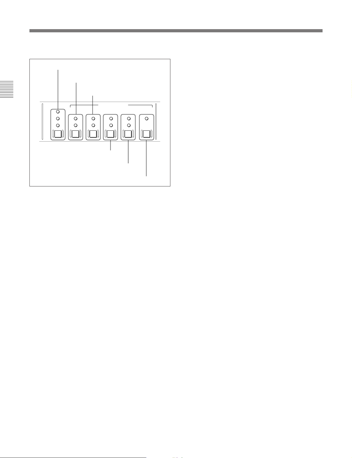
!¡ Time code setting section
TC switch and indicators
INT/EXT switch and indicators
Chapter 2 Location and Function of Parts
TC
LTC
AUTO
VITC
FREE RUN/REC RUN switch and
indicators
TC (time code) switch and indicators
This switch selects the time code displayed in the
lower control panel in the sequence: LTC
2)
n VITC
. The indicator corresponding to the
selection lights.
When AUTO is selected, the time code displayed is as
follows:
•For playback from tape
VITC when the tape transport speed is up to halfspeed, and LTC when it is more than half-speed.
•For playback from hard disk
File time code (see the section “Displayed time data
value,” page 4-7).
PRESET/REGEN switch and indicators
TC GENERATOR
INT
PRESET
EXT
REGEN
DF/NDF switch and indicators
FREE
RUN
REC
RUN
DF
NDF
VITC switch and indicator
VITC
ON
1)
n AUTO
PRESET/REGEN (preset/regenerated) switch and
indicators
This switch makes the following selection for the
internal time code generator:
PRESET: The initial value of the time code
produced by the internal time code generator can
be preset by a control panel operation or by
remote control from a device connected to the
REMOTE-IN(9P) connector.
REGEN: The internal time code generator is
synchronized to the playback time code read by
the internal time code reader.
The indicator corresponding to the selection lights.
FREE RUN/REC RUN switch and indicators
This switch selects the time code run mode of the
internal time code generator.
FREE RUN: Regardless of the operating mode of
this unit, the time code value advances
continuously while the power is on.
REC RUN: The time code value advances only
during recording. When this mode is selected, set
the INT/EXT switch to INT, and the PRESET/
REGEN switch to PRESET.
The indicator corresponding to the selection lights.
INT/EXT (internal/external) switch and indicators
This switch selects the time code used:
INT: The time code produced by the internal time
code generator.
EXT: The external time code selected as follows.
•When the TC switch is set to LTC or AUTO
The external time code input to the TIME CODE
IN connector.
•When the TC switch is set to VITC
The VITC time code included in the input video
signal.
..........................................................................................................................................................................................................
1) LTC: abbreviation of Longitudinal Time code. This
time code is recorded on a longitudinal track on the tape.
Reading is unreliable at low speeds, and not possible at
all during still playback.
2) VITC: abbreviation of Vertical Interval Time code.
This is inserted in the vertical blanking interval and
recorded on the video tracks. It can be read at low
speeds and during still playback, but not during highspeed playback.
2-6 Chapter 2 Location and Function of Parts
Page 15

DF/NDF (drop-frame/non-drop-frame) switch and
indicators
In a 525/60 system, this switch selects the
mode of advancing the time code generator and CTL
counter.
DF: Drop-frame mode.
NDF: Non-drop-frame mode.
1)
1)
The indicator corresponding to the selection lights.
Note
When the PRESET/REGEN switch is set to REGEN,
since the time code generator is synchronized to the
playback time code, this switch has no effect.
VITC switch and indicator
To record the time code produced by the internal time
code generator as a VITC, press this switch, lighting
the ON indicator.
When the ON indicator is off, internally generated
time code is not recorded as VITC, but VITC present
in the input video signal is recorded unchanged.
!™ REMOTE/LOCAL switch and indicator
To control this unit from a device connected to the
REMOTE-IN(9P) connector, press this switch, turning
the 9P indicator on.
Chapter 2 Location and Function of Parts
..........................................................................................................................................................................................................
1) Drop-frame/non-drop-frame mode: In the NTSC
system, the actual frame rate is 29.97 frames per second.
There is therefore a cumulative discrepancy between the
actual frame rate and the 30 frames per second rate on
which time code is based. In drop-frame mode, except
once every 10 minutes, the first two frames are skipped
at the beginning of each minute to keep the time code
values in step with actual elapsed time. In non-dropframe mode, the correction is not carried out, and there is
a discrepancy of about 86 seconds per day between
actual elapsed time and time code values.
Chapter 2 Location and Function of Parts 2-7
Page 16
2-1 Control Panels
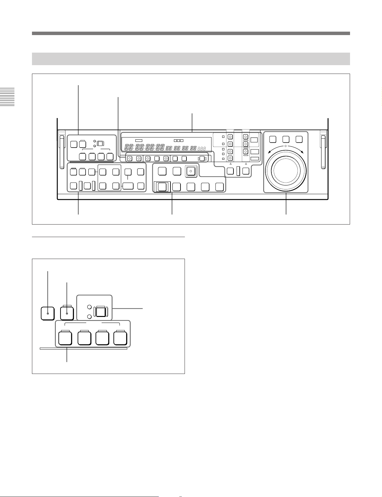
2-1-2 Lower Control Panel
1 Editing mode setting section
2 Monitor/menu/display setting section
Chapter 2 Location and Function of Parts
ASSEMBLE/
PREVIEW/
1 Editing mode setting section
1 ASSEMBLE/ALL button
2 VIDEO button
VIDEO
ALL
INS
OVL
CH-1
CH-2 CH-3 CH-4
UNDO RECALL DELETE
AUTO EDIT
REVIEW
EDITING
AUDIO
MODE
IN OUT
IN OUT
AUDIO
3 Device specification and display section
CH
CAPSTAN
CONDITION
VI TC UB
INTRP A IN DF LTC VITC 8F 4F 2F
PB EE PB MENU SET HOLD RESET
EVENT
FEED
ENTRY
INDEX
LOCK
A OUT
STANDBY PREROLL
EJECT REW PLAY F FWD STOP
6
CONFI ON
TCG TOTAL REMAIN 525 625
CTL/TC/UB TOTAL/REMAIN
REC
0
9
5 Tape/disk transport control section4 Editing control section
SHUTTLE JOG VAR
DISK
BUSY
REVERSE FORWARD
BETACAM
SX
ALARM
EVENT
)
FULL
EDIT
SIMPLE
DOLBY
NR
EDIT
REC
INHIBIT
%
KEY
INHIBIT
SERVO
PLAYER RECORDER
p
DISK
PROGRAM
DISK
MASTER
TAPE
EXT
6 Search control section
signals, time code signals, and so forth) are recorded
together.
2 VIDEO button
For insert editing on the hard disk, to select the video
signal, press this button, turning it on.
ASSEMBLE/
ALL
VIDEO
CH-1
EDITING
MODE
INS
OVL
AUDIO
CH-2 CH-3 CH-4
3 EDITING
MODE button
and indicators
3 EDITING MODE button and indicators
This button switches the mode used for nonlinear
editing insertion between insert mode (INS indicator
lit) and overlay mode (OVL indicator lit).
For details of nonlinear editing, see Chapter5, “Editing
Using the Built-in Hard Disk”.
4 AUDIO CH-1 to CH-4 buttons
4 AUDIO CH-1 to CH-4 (channel 1 to channel 4)
buttons
For insert editing on the hard disk, to select audio
1 ASSEMBLE/ALL button
Press this button, turning it on, in the following cases:
1)
•To carry out assemble editing
•To carry out all-channel insert editing
using tape.
2)
using the hard
channels 1 to 4, press these buttons, turning them on.
You can select any number of the channels.
disk.
In both of these cases, all signals (video signals, audio
..........................................................................................................................................................................................................
1) Assemble editing: Editing in which new video/audio is
added in sequence to the end of existing recorded video/
audio.
2) Insert editing: Editing in which new video/audio is
added into the middle of existing recorded video/audio.
2-8 Chapter 2 Location and Function of Parts
Page 17
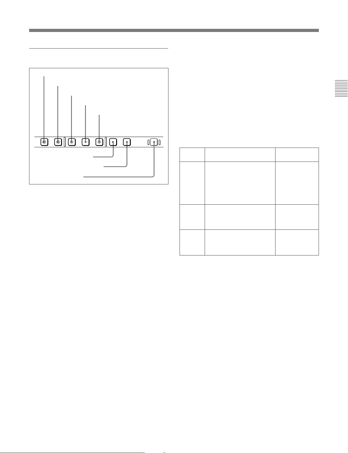
2 Monitor/menu/display setting section
1 PB.EE button
2 PB button
3 MENU button
4 SET button
5 HOLD button
PB EE PB MENU SET HOLD RESET
CTL/TC/UB TOTAL/REMAIN
5 HOLD button
To stop updating of the time code or user bit value in
the fluorescent display (that is, to hold the display),
press this button, turning it on. To set a time code or
user bit value, first press this button to hold the value.
6 CTL/TC/UB button
This selects the value displayed in the fluorescent
display in the following sequence: CTL, TC, UB. As
the display changes, the corresponding indicators over
the fluorescent display also show the status.
Time code display value selection and display contents
Chapter 2 Location and Function of Parts
6 CTL/TC/UB button
7 TOTAL/REMAIN button
8 RESET button
1 PB.EE (playback E-E) button
To select E-E mode input signals for the video/audio
signals output during fast forward, rewind, still, and
standby, press this button, turning it on.
Either one of this button and the PB button 2 is
always lit.
2 PB (playback) button
To select playback signals for the video/audio signals
output during fast forward, rewind, still, and standby,
press this button, turning it on.
Either one of this button and the PB.EE button 1 is
always lit.
3 MENU button
Use this button for setup menu operations.
Pressing this button, turning it on, displays setup
menus in the fluorescent display of the device
specification and display section 3. Press the button
once more to exit from the menu display.
Display
selection
CTL Tape running time (hours,
TC Playback time code read by
UB User bit value inserted in the
Value displayed
minutes, seconds, frames)
computed from the CTL
(control) signal recorded on
the tape during playback, or
a count of the CTL signal
pulses during recording.
the internal time code reader
or time code during
recording.
playback time code or time
code during recording.
a)
a)
Indicator status
TC and UB
indicators are
both off.
The TC indicator
lights and the UB
indicator goes
off.
The UB indicator
lights and the TC
indicator goes
off.
a) The selection of LTC or VITC is made by the TC switch.
When VITC is selected, the VITC indicator over the TC
switch lights.
7 TOTAL/REMAIN button
Press this button to switch between a TOTAL
indication or REMAIN (remaining) indication on the
fluorescent display. According to the selection, the
TOTAL indicator or REMAIN indicator above the
fluorescent display lights.
The TOTAL and REMAIN indications vary according
to that on which operations are being carried out.
For details of setup menu operations, see Chapter7, “Menu
System”.
4 SET button
Use this button for setting time code and user bit
values and in setup menu operations.
For details of setup menu operations see Chapter7, “Menu
System”, and for details of setting time code and user bit
values see Section 4-1-2 “Recording Time code and User
Bit Values” (page 4-2).
For details of the TOTAL and REMAIN indications, see the
table “TOTAL/REMAIN indications” (page 2-10).
8 RESET button
To reset a CTL, time code (TC) or user bit (UB) value
displayed in the fluorescent display, hold this button
down.
Resetting the CTL value erases all edit points.
Chapter 2 Location and Function of Parts 2-9
Page 18

2-1 Control Panels
3 Device specification and display section
1 Fluorescent display and indicators
2 Device specification buttons and indicators
Chapter 2 Location and Function of Parts
VI TC UB
1 Fluorescent display and indicators
This comprises a time data display area 1, a time data
display area 2, and an event display area provided by
the fluorescent display, and also a number of
indicators.
3 Indicators
CAPSTAN
LOCK
INTRP A IN DF LTC VITC 8F 4F 2F
A OUT
4 PLAYER button and RECORDER button
Indicator area
CH
CONDITION
TCG TOTAL REMAIN 525 625
CONFI ON
EVENT
Time data display area 2
This shows a TOTAL time indication or REMAIN
(remaining) time indication according to the setting of
the TOTAL/REMAIN button in the monitor/menu/
display setting section 2. Depending on the display,
the corresponding one of the TOTAL and REMAIN
indicators immediately above lights.
DOLBY
NR
FULL
EDIT
SIMPLE
EDIT
%
REC
INHIBIT
KEY
INHIBIT
SERVO
PLAYER RECORDER
DISK
PROGRAM
DISK
MASTER
TAPE
EXT
DISK
BUSY
BETACAM
SX
ALARM
CH
CAPSTAN
CONDITION
VI TC UB
INTRP A IN DF LTC VITC 8F 4F 2F
LOCK
A OUT
TCG TOTAL REMAIN 525 625
CONFI ON
EVENT
DOLBY
NR
%
Event display area
Time data display area 2
Time data display area 1
Time data display area 1
Normally this displays a CTL count, time code value,
or user bit value according to the setting of the CTL/
TC/UB button in the monitor/menu/display setting
section 2 and the setting of the TC switch in the
upper control panel.
It is also used to display an IN point (or audio IN
point), a duration, error messages, setup menus, and so
forth.
For details of the selection of CTL count, time code value,
or user bit value see the description of the CTL/TC/UB
button (previous page).
2-10 Chapter 2 Location and Function of Parts
TOTAL/REMAIN indications
Device
subject to
operations
DISK
MASTER
a)
REMAIN
selection
TOTAL
REMAIN
DisplayTOTAL/
Total number of frames recorded
on disk.
Number of frames of remaining
unrecorded capacity of disk.
DISK
PROGRAM
b)
TOTAL
REMAIN
Total length (frames) of program
created by editing.
Remaining length (frames) of
program during playback.
TAPE TOTAL Time value representing the total
tape length.
REMAIN Time value representing the
remaining tape length.
C)
C)
a) In the following description, “DISK MASTER” is also
referred to simply as “MASTER”.
b) In the following description, “DISK PROGRAM” is also
referred to simply as “PROGRAM”.
c) This is an approximate value calculated on the basis of
the detected tape diameter. It is not precise to units of
seconds.
Page 19

In the following cases, “---------” appears as the
TOTAL/REMAIN indication.
•When TAPE has been specified as the device subject
to operations and either no cassette has been loaded
or the loaded cassette has not started running, or
when the remaining tape length has not yet been
calculated because the tape started running only
seconds before.
•When there is no edited program with PROGRAM
specified as the device subject to operations
•INTRP (interpolation) indicator: This lights
when a playback time code reading error is
interpolated using the CTL signal.
•DF (drop-frame) indicator: This lights when a
displayed time code value is in drop-frame mode.
•LTC, VITC indicators: Regardless of the display
in the time data display area 1, these indicators
light when the corresponding time code values are
being read or recorded (during recording).
•CAPSTAN LOCK 8F/4F/2F (8 fields/4 fields/2
fields) indicators: The indicator lights
For details of the device subject to operations, see the item
about the device specification buttons (page 2-12).
corresponding to the mode selected by the
CAPSTAN LOCK switch on the subsidiary
control panel or in setup menu item 106.
This area is also used to display an OUT point (or
audio OUT point), a time code value produced by the
time code generator, a duration, error messages, setup
menus, and so forth.
•CH (channel) CONDITION indicator: A threecolor indicator shows the state of the playback
signal.
Green: The state of the playback signal is good.
Yellow: The playback signal is somewhat
Event display area
This normally displays the number of events registered
during multi-event editing.
This is also used to display setup menu settings and
feed speeds.
For details of multi-event editing, see Section 5-3, “MultiEvent Editing” (page 5-14).
Indicator area
This includes the following indicators.
•A (audio) IN indicator: When an IN point is
displayed in time data display area 1, the IN
indicator lights, and when an audio IN point is
displayed, the A indicator lights in addition to the
IN indicator.
•TC (time code) indicator: This lights when a time
code is displayed in the time data display area 1.
•UB (user bits) indicator: This lights when a user
bit value is displayed in the time data display area
1.
•VI (VITC) indicator: When a VITC time code
value or VITC user bit value is displayed in the
time data display area 1, this indicator lights
together with the TC or UB indicator.
deteriorated, but playback is possible.
Red: The playback signal is deteriorated.
When this indicator remains on, head cleaning
or an internal inspection is necessary.
•CONFI (confidence) ON indicator: This indicates
1)
the state of the VTR CONFI playback
function.
When the CONFI playback function is enabled,
the CONFI indicator lights, and when CONFI
playback is actually being carried out the ON
indicator also lights.
CONFI playback settings are carried out using
extended menu item 316.
•A (audio) OUT indicator: When an OUT point is
displayed in time data display area 2, the OUT
indicator lights, and when an audio OUT point is
displayed, the A indicator lights in addition to the
OUT indicator.
•TCG (time code generator) indicator: This lights
when a time code generated by the internal time
code generator is displayed in the time data
display area 2.
•TOTAL, REMAIN indicators: When the
“TOTAL” time is displayed in time data display
area 2 the TOTAL indicator lights, and when the
“REMAIN” time is displayed in time data display
area 2 the REMAIN indicator lights.
..........................................................................................................................................................................................................
Chapter 2 Location and Function of Parts
1) CONFI playback: This refers to playback of the audio
and video signals immediately after recording, using the
confidence heads, the signal being output to all intents
and purposes simultaneously with recording. This is used
to check recording.
Chapter 2 Location and Function of Parts 2-11
Page 20
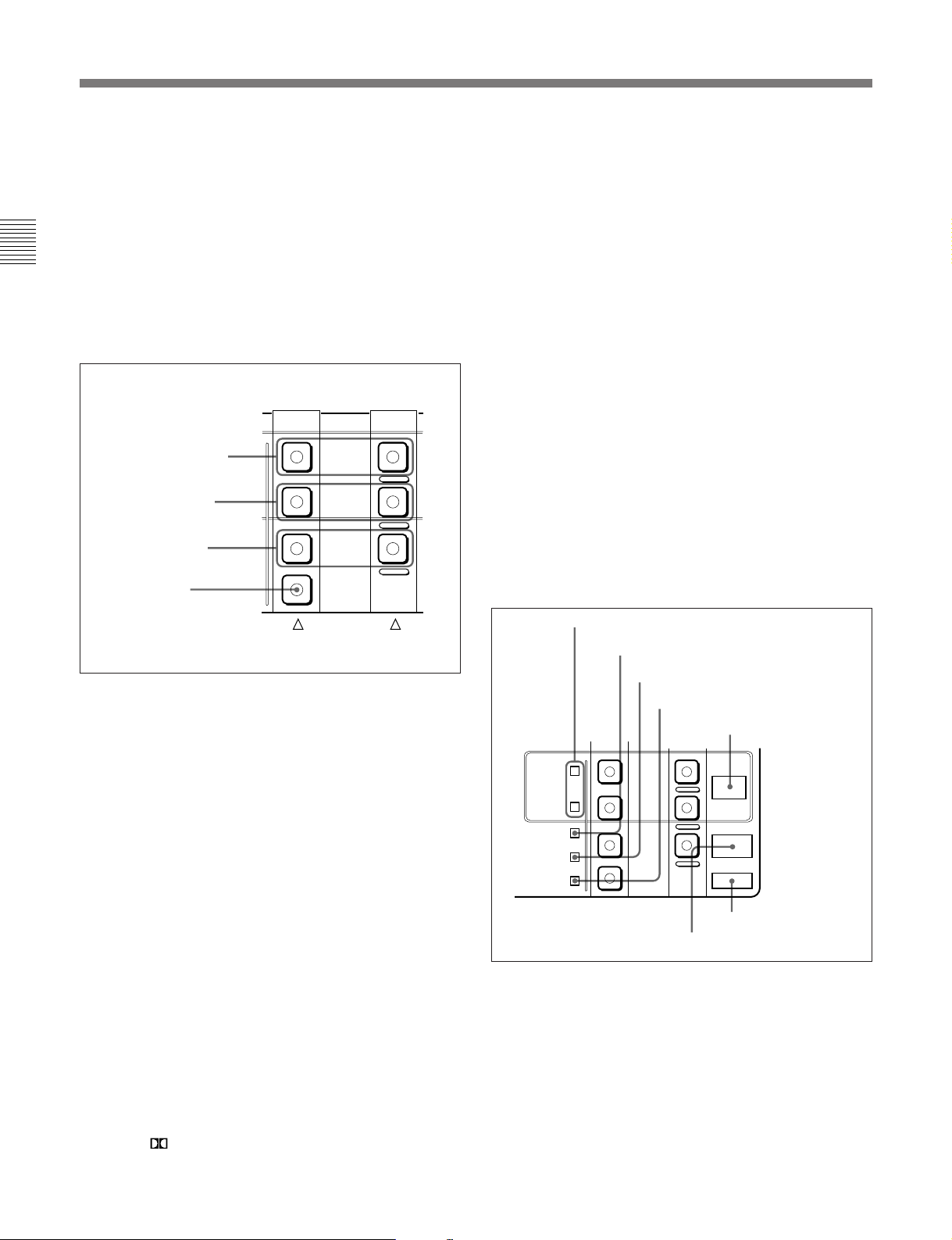
2-1 Control Panels
•525, 625: The indicator showing the number of
scan lines for the television standard selected
using basic menu item 013 lights (NTSC: 525
scan lines, field frequency 60 Hz; PAL: 625 scan
lines, field frequency 50 Hz).
•DOLBY NR indicator: This lights when the Dolby
Chapter 2 Location and Function of Parts
noise-reduction
•EVENT indicator: This lights when an event is
displayed in the event display area.
2 Device specification buttons
DISK PROGRAM
buttons
DISK MASTER
buttons
TAPE buttons
EXT button
1)
circuit is functioning.
Player side Recorder side
DISK
PROGRAM
DISK
MASTER
TAPE
EXT
DISK MASTER buttons
When using the hard disk of this unit for recording or
playing back material before editing, specify the hard
disk as player or recorder. According as you wish to
specify the hard disk as player or recorder, hold down
the PLAYER or RECORDER button and press the
DISK MASTER button on the PLAYER side or
RECORDER side, turning it on.
The device selected by pressing these buttons is also
referred to simply as “MASTER”.
TAPE buttons
To specify the VTR of this unit as player or recorder,
hold down the PLAYER or RECORDER button and
press the TAPE button on the PLAYER side or
RECORDER side, turning it on.
EXT (external) button
To specify the device connected to the REMOTEIN(9P) connector as player, hold down the PLAYER
button and press this button, turning it on.
3 Indicators
FULL EDIT/SIMPLE EDIT indicators
PLAYER RECORDER
DISK PROGRAM buttons
When using the hard disk of this unit for nonlinear
REC INHIBIT indicator
KEY INHIBIT indicator
SERVO indicator
DISK BUSY indicator
editing, specify the hard disk as player or recorder.
According as you wish to specify the hard disk as
player or recorder, hold down the PLAYER or
RECORDER button and press the DISK PROGRAM
button on the PLAYER side or RECORDER side,
turning it on.
The device selected by pressing these buttons is also
referred to simply as “PROGRAM”.
..........................................................................................................................................................................................................
FULL
EDIT
SIMPLE
EDIT
REC
INHIBIT
KEY
INHIBIT
SERVO
DISK
PROGRAM
DISK
MASTER
TAPE
EXT
BETACAM SX indicator
DISK
BUSY
BETACAM
SX
ALARM
ALARM indicator
1) Dolby noise-reduction: Dolby noise reduction
manufactured under license from Dolby Laboratories
Licensing Corporation. “ DOLBY” and the double-D
symbol are trademarks of Dolby Laboratories
Licensing Corporation.
2-12 Chapter 2 Location and Function of Parts
Page 21

DISK BUSY indicator
This lights in the following cases:
•When the hard disk is being readied for operation
immediately after power-on
•When the hard disk is being accessed.
When the hard disk is being warmed up, this indicator
slowly flashes. In this case, wailt until the indicator
goes off.
Note
While this indicator is lit, do not power off the unit.
There is a possibility of data on the hard disk being
damaged or destroyed.
ALARM indicator
This lights when a hardware error is detected on the
unit, and goes off when the error is resolved.
When this indicator is lit, an error message appears in
the fluorescent display. If you are using the
COMPOSITE VIDEO OUTPUT 3 (SUPER)
connector, then when the CHARACTER switch in the
subsidiary control panel is set to ON, the error
message also appears on the monitor screen.
FULL EDIT/SIMPLE EDIT indicators
When full edit mode is specified as the editing mode
for the disk, the FULL EDIT indicator lights, and
when simple edit mode is specified as the editing mode
for the disk, the SIMPLE EDIT indicator lights.
In the full edit mode, split editing for each of the video
and audio channels is possible. In the simple edit
mode, split editing is not possible.
When you are carrying out nonlinear editing with an
editor connected to this unit, select full edit mode.
In the simple edit mode the maximum possible speed
of data transfer to the built-in hard disk is four times
normal speed, and in the full edit mode it is three times
normal speed.
You can select simple edit mode or full edit mode
using the disk file management menu.
For more information, see Section 7-4, “Disk File
Management Menu” (page 7-25).
KEY INHIBIT indicator
This indicator lights when the KEY INHIBIT switch
on the subsidiary control panel is set to ON.
Chapter 2 Location and Function of Parts
BETACAM SX indicator
When recording in Betacam SX format or playing
back a tape recorded in Betacam SX format, this
indicator lights.
REC (recording) INHIBIT indicator
This indicator is on or off according to the
combination of the setting of the REC INHIBIT switch
on the subsidiary control panel and the record inhibit
plug on the cassette, as shown in the following table.
When this indicator is on, recording on tape is
prohibited.
REC INHIBIT indicator indications
REC INHIBIT
switch position
ON Record inhibit/permit Lit
OFF Record inhibit Lit
a) It is possible to make a setting (extended menu item 107)
so that in this case the indicator flashes.
State of the record
inhibit plug on the
cassette
Record permit Off
REC INHIBIT
indicator
state
a)
SERVO indicator
1)
When the drum servo and capstan servo are locked
,
this indicator lights.
..........................................................................................................................................................................................................
1) Servo lock: This refers to the synchronization of the
phase of the drum rotation and the reference signal for the
tape transport position, so that the video heads can trace
the same pattern on the tape for playback or recording.
Chapter 2 Location and Function of Parts 2-13
Page 22
2-1 Control Panels
4 PLAYER button and RECORDER button
When carrying out editing using a player and recorder,
select each of the devices.
•To select the player: press the PLAYER button,
turning it on. (PLAYER mode)
•To select the recorder: press the RECORDER button,
Chapter 2 Location and Function of Parts
turning it on. (RECORDER mode)
•To select both the recorder and the player: press the
RECORDER button and the PLAYER button
simultaneously, turning both of them on. (“PARA
RUN” mode)
In this case, extended menu item 201 must already
have been set to PARA RUN ENABLE.
When an external device (EXT) is specified as the
player and if it is not in the remote mode, neither of the
buttons lights. In this case, operations apply to the
device specified as the recorder.
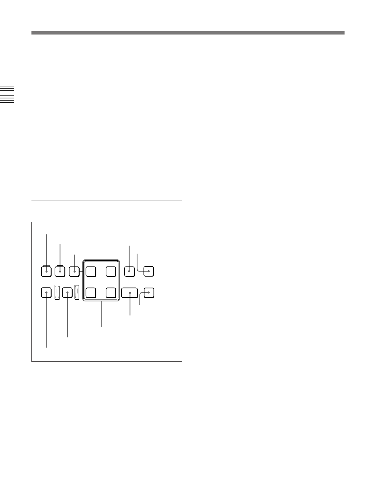
4 Editing control section
1 UNDO button
2 RECALL button
UNDO RECALL DELETE
3 DELETE button
AUDIO
IN OUT
4 EVENT button
5 FEED button
EVENT
FEED
2 RECALL button
During playback of a program (DISK PROGRAM) or
when playback is stopped, pressing this button while
holding down the EVENT button recalls the IN and
OUT points of the event being played back, causing
the IN and OUT buttons to light. Use this button when
you wish to modify the IN and OUT points.
3 DELETE button
This deletes an edit point or event.
Hold down this button and press the IN, OUT, AUDIO
IN, AUDIO OUT, or EVENT button according to the
what you wish to delete. If the button (IN, OUT,
AUDIO IN, or AUDIO OUT) which you pressed to
make the deletion flashes, it is necessary to set the
deleted edit point again.
4 EVENT button
Use this button when you wish to save two or more
player editing segments (each segment being between
an edit IN point and OUT point) as an “event”, and
carry out automatic editing of all the events together
(multi-event editing).
To save events, after setting each editing segment,
hold down this button and press the ENTRY button.
This is also used for other operations relating to
events.
PREVIEW/
REVIEW
AUTO EDIT
9 AUTO EDIT button
0 PREVIEW/REVIEW button
IN OUT
8 Edit point setting buttons
ENTRY
INDEX
6 INDEX button
7 ENTRY button
1 UNDO button
Use this in nonlinear editing to undo the effect of the
immediately previous automatic editing operation, and
return to the previous state.
This button lights, and the AUTO EDIT button flashes.
To return to the state before the immediately previous
automatic editing operation, press the AUTO EDIT
button. To cancel the undo operation, press this button
again, turning it off.
For details of operations relating to events, see Section 5-3,
“Multi-Event Editing” (page 5-14) and Section 5-4,
“Special Nonlinear Editing Operations” (page 5-17).
5 FEED button (DNW-A100/A100P only)
Use this button when you wish to carry out dubbing
from tape or the hard disk to an external device or
high-speed automatic editing from tape to the hard disk
at any speed from 0.1 to 4 times normal.
To play back in feed mode, hold down this button and
press the PLAY button.
For details of operations in feed mode, see the section
“Carrying out playback in feed mode” (page 4-10) and the
section “Carrying out high-speed editing in feed mode”
(page 5-11).
2-14 Chapter 2 Location and Function of Parts
Page 23
6 INDEX button
Use this in the following cases:
•During playback of a Betacam SX format tape
For cuing up to the point where index information
(good shot marker or recording start marker) is
recorded on a Betacam SX camcorder tape
•During playback from the hard disk
For cuing up to a particular event
For details, see the items for the F FWD button and REW
button (see page 2-17).
7 ENTRY button
Use this for setting edit points, saving events and so
forth.
•To set a video IN point or OUT point: Hold down
the IN button or OUT button, and press this button.
•To set an audio IN point or OUT point: Hold down
the AUDIO IN button or AUDIO OUT button, and
press this button.
•To save an event: Hold down the EVENT button,
and press this button.
For details of operations relating to events, see Section 5-3,
“Multi-Event Editing” (page 5-14) and Section 5-4,
“Special Nonlinear Editing Operations” (page 5-17).
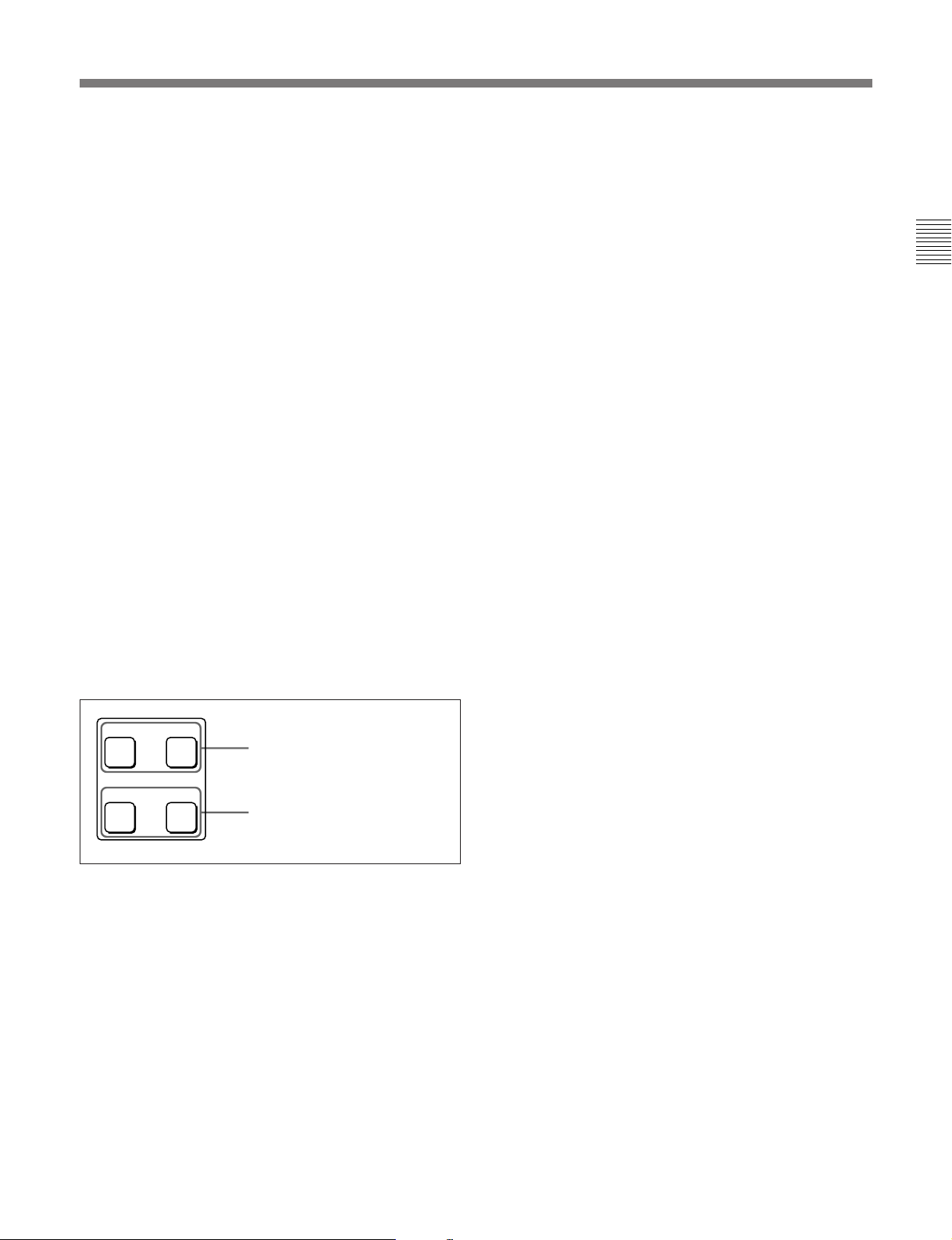
8 Edit point setting buttons
AUDIO
IN OUT
AUDIO IN button and AUDIO
OUT button
AUDIO IN button and AUDIO OUT button
In insert editing of the program, to set an audio IN
point or audio OUT point separate from the
corresponding video edit point, hold down the AUDIO
IN button or AUDIO OUT button, and press the
ENTRY button.
After you have made the setting, pressing the AUDIO
IN button or AUDIO OUT button displays the audio
IN point or audio OUT point set on the fluorescent
display.
9 AUTO (automatic) EDIT button
After edit point setting, to carry out automatic editing
(recording), press this button, turning it on.
If the IN point is not set, the automatic editing is
carried out with the point where you pressed this
button as the IN point.
If you pressed the PREVIEW/REVIEW button to carry
out a preview, when the preview ends it flashes.
0 PREVIEW/REVIEW button
After edit point setting, to preview the editing results
on the monitor before recording, press this button,
turning it on.
If the IN point is not set, the preview is carried out
with the point where you pressed this button as the IN
point.
During the preview it is lit, and when the preview ends
it flashes.
Use this button also to carry out a review of the editing
results after carrying out automatic editing.
Chapter 2 Location and Function of Parts
IN OUT
IN button and OUT button
IN button and OUT button
To set a video IN point or OUT point, hold down the
IN button or OUT button, and press the ENTRY
button.
After you have made the setting, pressing the IN
button or OUT button displays the IN point or OUT
point set on the fluorescent display.
Chapter 2 Location and Function of Parts 2-15
Page 24
2-1 Control Panels
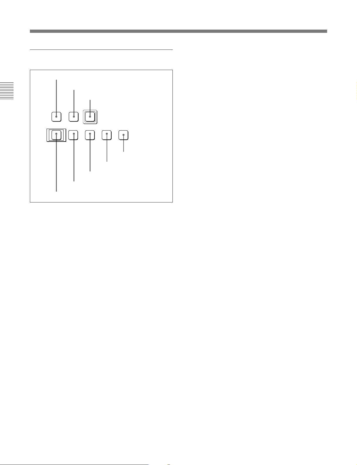
5 Tape/disk transport control section
1 STANDBY button
Chapter 2 Location and Function of Parts
STANDBY PREROLL
EJECT REW PLAY F FWD STOP
6
8 EJECT button
1 STANDBY button
Use this as follows, depending on the currently
selected device.
For TAPE
When a cassette is inserted and this button is off, to put
the VTR in standby mode, press the button, turning it
on.
In standby mode, the drum is rotating and the tape is in
contact with the drum. As a result, recording or
playback can start immediately.
To end standby mode, press the STANDBY button,
turning it off.
If 8 minutes (value can be varied using extended menu
item 501) elapse in standby mode, the unit
automatically switches out of standby mode to protect
the tape.
2 PREROLL button
3 REC button
REC
0
7 REW button
)
9
5 F FWD button
6 PLAY button
p
4 STOP button
2 PREROLL button
Press this button to cue up to the preroll point (before
the IN point by the time set as the preroll time) on the
tape or hard disk. You can change or select the preroll
time and the state of the unit at the end of preroll
1)
(“stop mode”
or still playback mode) using basic
menu item 001 or extended menu item 401.
Cuing up edit points
Hold down the IN, OUT, AUDIO IN, or AUDIO OUT
button while pressing this button to cue up to the
corresponding edit point.
3 REC (record) button
To start recording, press this button together with the
PLAY button, turning it on.
Monitoring in E-E mode
When the unit is in stop mode, when you press this
button it lights, and you can monitor the video and
audio in E-E mode. To return to the original state,
press the STOP button.
During playback, search, fast forward, or rewind,
while this button is held down you can monitor the
video and audio in E-E mode. In this case the button
does not light.
4 STOP button
To stop recording or playback, press this button,
turning it on.
When you stop playback, the unit switches either to
still playback or to E-E mode according to setup menu
settings, and the settings of the PB.EE button and PB
button.
For MASTER or PROGRAM
Pressing this button has no effect. When a file on the
hard disk is open for recording or playback, this button
lights.
..........................................................................................................................................................................................................
1) Stop mode: the state in which the device currently the
subject of operation is stopped, and the STOP button is
lit.
2-16 Chapter 2 Location and Function of Parts
Page 25

Fault display function
This flashes in the following cases related to reference
signals:
•When the player is EXT.
– When the OUT REF switch on the subsidiary
control panel is set to INPUT VIDEO, and there is
no input video signal.
– When the OUT REF switch on the subsidiary
control panel is set to REF, and there is no
external reference signal input or the input
external reference signal is not synchronized to the
input video signal.
•When the player is other than EXT (when the player
is an internal device)
There is no external reference signal input, regardless
of the setting of the OUT REF switch on the
subsidiary control panel.
You can disable this function using extended menu
item 105.
5 F FWD (fast forward) button
To use this button, press it, turning it on. Its function
depends on the currently selected device, as follows.
For TAPE
This fast forwards the tape.
While the INDEX button is lit, this cues up to index
information detected during the fast forwarding
operation.
For MASTER or PROGRAM
The effect in this case depends on whether the INDEX
button is lit or off, as follows:
•When the INDEX button is off:
Skips to the end of the last file or event.
•When the INDEX button is lit:
Skips to the beginning of the next file or event.
If the current file or event is the last one, skips to its
end.
When events are being manually recorded on the hard
disk (MASTER), the event currently being recorded is
regarded as the last event.
For information about the relationship between files and
events, see Section 5-1, “Overview” (page 5-1).
6 PLAY button
To start playback, press this button, turning it on.
To operate in capstan override mode (when using
tape)
Hold down this button, and turn the search dial.
For details of capstan override mode, see the item relating
to the search dial (page 2-18).
7 REW (rewind) button
To use this button, press it, turning it on. Its function
depends on the currently selected device, as follows.
For TAPE
This rewinds the tape.
While the INDEX button is lit, this cues up to index
information detected during the rewinding operation.
For MASTER or PROGRAM
The effect in this case depends on whether the INDEX
button is lit or off, as follows:
•When the INDEX button is off:
Skips to the beginning of the first file or event.
•When the INDEX button is lit:
Skips to the beginning of the current file or event.
When the unit is in record mode, recording ends.
If the current position is at the beginning of a file or
event, skips to the beginning of the previous file or
event.
8 EJECT button
Use this as follows, depending on the currently
selected device.
For TAPE
Press this button to eject the cassette. While the
cassette is being ejected, this button lights.
For MASTER or PROGRAM
Press this button to close a file.
This aborts the current operation, and closes the file.
The STANDBY button goes off, and the EJECT
button lights.
Chapter 2 Location and Function of Parts
Chapter 2 Location and Function of Parts 2-17
Page 26
2-1 Control Panels
6 Search control section
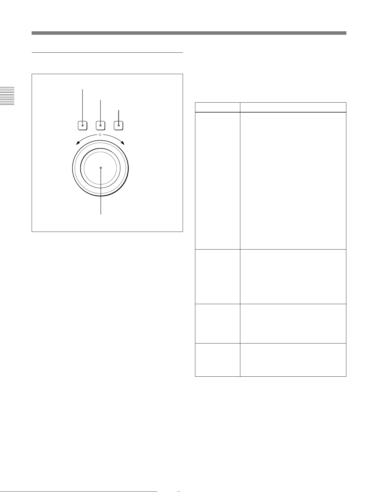
Chapter 2 Location and Function of Parts
1 SHUTTLE button
To use the search dial for playback in shuttle mode,
press this button, turning it on.
For details of playback in shuttle mode, see the item for the
search dial 4.
2 JOG button
To use the search dial for playback in jog mode, press
this button, turning it on.
For details of playback in jog mode, see the item for the
search dial 4.
3 VAR (variable) button
To use the search dial for playback in variable speed
mode, press this button, turning it on.
1 SHUTTLE button
2 JOG button
3 VAR button
SHUTTLE JOG VAR
REVERSE FORWARD
4 Search dial
You can carry out noiseless playback over the whole
playback speed range from the hard disk, and in the
range of ±1 times normal speed from a Betacam SX
format tape.
Playback modes using the search dial
Playback mode Operations and functions
Shuttle Press the SHUTTLE button or the search
Jog Press the JOG button or the search dial
Variable speed Press the VAR button, turning it on, then
Capstan
override (using
a tape)
dial so that the SHUTTLE button lights,
then turn the search dial. Playback is
carried out at a speed determined by the
position of the search dial. The playback
speed range is as follows:
•Using a Betacam SX tape: –50 to +50
times normal speed
•Using an analog Betacam tape: –35 to
+35 times normal speed for DNW-A100/
A50/A45 or –42 to +42 times normal
speed for DNW-A100P/A50P/A45P
•Using the hard disk: –100 to +100 times
normal speed
The search dial has detents at the still
position and at ±10 times normal speed.
The maximum shuttle mode playback
speed can be changed by changing the
setting of item 102 in the extended menu
(see page 7-9)
so that the JOG button lights, then turn
the search dial. Playback is carried out
at a speed determined by the speed of
rotation of the search dial. The playback
speed range is –1 to +1 time normal
speed:
The search dial has no detents.
turn the search dial. You can control the
playback speed finely (47 steps) in the
range of ±1 times normal speed.
The search dial has detents at the still
position and at ±1 times normal speed.
Hold down the PLAY button and turn the
search dial to adjust the playback speed
in the range of ±15%. Use this for phase
adjustment between this unit and an
external connected device.
.
For details of playback in variable mode, see the item for
the search dial 4.
4 Search dial
Turn this to carry out playback in the modes shown in
the following table. Turn the dial clockwise for
forward playback and counterclockwise for reverse
playback.
Pressing the dial toggles between shuttle and jog
modes or between variable and jog modes.
2-18 Chapter 2 Location and Function of Parts
Changing the setting of extended menu item 101
enables you to use the search dial alone to select
shuttle/jog/variable speed modes, without using the
SHUTTLE, JOG, and VAR buttons.
Page 27
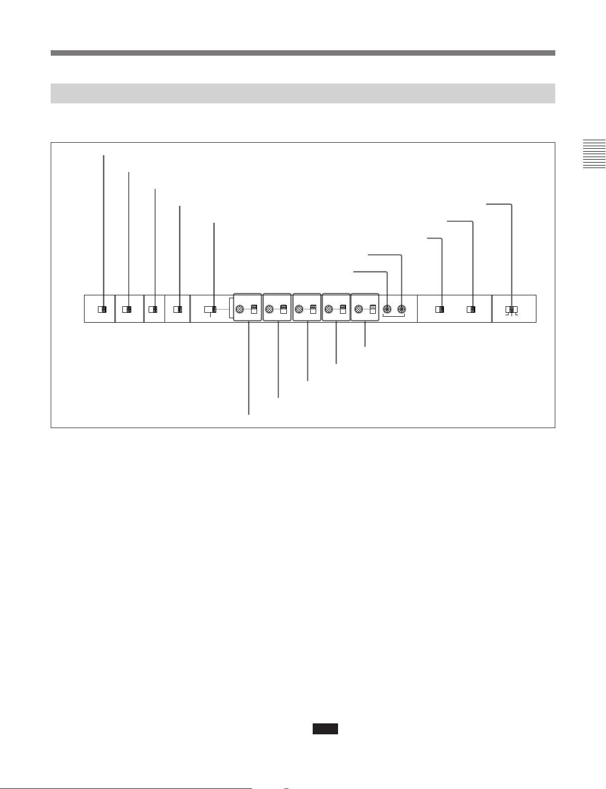
2-1-3 Subsidiary Control Panel
Pull out the lower control panel to reveal the
subsidiary control panel.
1 EMPHASIS switch
2 CHARACTER switch
3 DOLBY NR switch
4 OUT REF switch
5 PROCESS
CONTROL switch
VIDEO
EMPHASIS CHARACTER DOLBY
ON OFF OFF ON OFF ON
NR
OUT REF
INPUT
REF REMOTE LOCAL
VIDEO
PROCESS
CONTROL
MENU
CHROMA SET UP Y/C DELAY CHROMA PHASE SYNC SC
PRESET
PRESET
MANUAL
6 VIDEO knob and PRESET/MANUAL switch
MANUAL
7 CHROMA knob and PRESET/MANUAL switch
1 EMPHASIS switch
Set this to ON to apply emphasis to an analog input
audio signal or analog playback audio signal to convert
the analog audio signal to a digital audio signal.
2 CHARACTER switch
Select whether or not to superimpose text information
such as time code, menu settings, and alarm messages
on the video signal output from the COMPOSITE
VIDEO OUTPUT 3 (SUPER) connector.
ON: Superimposed text.
OFF: No superimposed text.
The factory default setting is ON.
3 DOLBY NR (noise reduction) switch
When using an oxide tape, switch the Dolby noisereduction system for analog audio on or off.
When using metal tape, the Dolby noise-reduction
system is automatically switched on, regardless of the
setting of this switch.
ON: Enable the Dolby noise-reduction system for
playback of an analog Betacam oxide tape.
!∞ CAPSTAN LOCK switch
!¢ KEY INHIBIT switch
!£ REC INHIBIT switch
!™ SC knob
!¡ SYNC knob
PRESET
PRESET
MANUAL
8 SET UP (DNW-A100/A50/A45)/BLACK LEVEL (DNW-A100P/A50P/
MANUAL
9 Y/C DELAY knob and PRESET/MANUAL switch
A45P) knob and PRESET/MANUAL switch
PRESET
MANUAL
SYSTEM PHASE
0 CHROMA PHASE knob and PRESET/MANUAL
switch
REC
INHIBIT
ON OFF ON OFF 2FD 8FD
KEY
INHIBIT
CAPSTAN
LOCK
4FD
(625/50)
OFF: Disable the Dolby noise-reduction system for
playback of an analog Betacam oxide tape.
The factory default setting is OFF.
4 OUT REF (reference) switch
When the device specification buttons (see page 2-12)
are set to select an external device (EXT) as the player,
this switch selects the reference signal for this unit
depending on the combination of the setting of
extended menu item 309 and the operating state of the
unit. (If other than an external device is specified as
the player, then regardless of the setting of this switch,
the signal input to the REF. VIDEO connector is
always selected as the reference signal.)
REF: Use the signal input to the REF. VIDEO
connector as the reference signal. During
recording input digital audio and video signals
must be synchronized with this signal.
INPUT VIDEO: Use the input video signal selected
by the VIDEO INPUT SELECT switch as the
reference signal.
Note
Operating this switch during playback may cause a
momentary interruption of the playback sound.
Chapter 2 Location and Function of Parts 2-19
Chapter 2 Location and Function of Parts
Page 28

2-1 Control Panels
5 PROCESS CONTROL switch
This selects the method of control of the internal
digital video processor.
REMOTE: Select this position to use an optional
BVR-50/50P Remote Control Unit for remote
control of the internal digital video processor.
Chapter 2 Location and Function of Parts
MENU: Select this position to use setup menus to
change the settings for the internal digital video
processor.
LOCAL: Select this position to use the subsidiary
control panel to change the settings for the internal
digital video processor.
6 VIDEO knob and PRESET/MANUAL switch
The switch makes the selection described immediately
below. When it is set to MANUAL, you can use the
knob to adjust the video signal output level.
PRESET: Regardless of the position of the knob,
the video signal output level is set to the reference
value.
MANUAL: You can adjust the video signal output
level in the range ±3 dB.
You can change the adjustment range using
extended menu item 714.
7 CHROMA (chrominance) knob and PRESET/
MANUAL switch
The switch makes the selection described immediately
below. When it is set to MANUAL, you can use the
knob to adjust the chrominance signal output level.
PRESET: Regardless of the position of the knob,
the chrominance signal output level is set to the
reference value.
MANUAL: You can adjust the chrominance signal
output level in the range ±3 dB.
You can change the adjustment range using
extended menu item 714.
8 SET UP (DNW-A100/A50/A45) / BLACK
LEVEL (DNW-A100P/A50P/A45P) knob and
PRESET/MANUAL switch
The switch makes the selection described immediately
below. When it is set to MANUAL, you can use the
knob to adjust the (black) setup level (525/60 system)
or black level (625/50 system).
PRESET: Regardless of the position of the knob,
the setup level (525/60 system) or black level
(625/50 system) is set to the reference value.
MANUAL: You can adjust the setup level (525/60
1)
system) in the range ±30 IRE
, or the black level
(625/50 system) in the range ±210 mV.
9 Y/C DELAY knob and PRESET/MANUAL
switch
The switch is effective only for playback of video
recorded in Betacam or Betacam SP format. It makes
the selection described immediately below. When it is
set to MANUAL, you can use the knob to adjust the Y/
C delay.
PRESET: Regardless of the position of the knob,
the Y/C delay is set to the reference value.
MANUAL: You can adjust the Y/C delay in the
range ±100 ns.
0 CHROMA (chrominance) PHASE knob and
PRESET/MANUAL switch
The switch makes the selection described immediately
below. When it is set to MANUAL, you can use the
knob to adjust the chrominance phase (the phase
difference from a burst signal).
PRESET: Regardless of the position of the knob,
the chrominance phase is set to the reference
value.
MANUAL: You can adjust the chrominance phase
in the range ±30°.
!¡ SYNC knob
This adjusts the output signal sync phase with respect
to the input reference signal to this unit, in a range of
±15 µs.
Use this adjustment when the output phase of this unit
is not accurately aligned with the reference signal
phase, or when carrying out special effects editing with
this unit and other VTRs connected to a switcher or
other equipment.
..........................................................................................................................................................................................................
1) IRE: A unit for representing a video level laid down by
the IRE (Institute of Radio Engineers). The IRE is now
the IEEE (Institute of Electrical and Electronic
Engineers).
2-20 Chapter 2 Location and Function of Parts
Page 29

!™ SC (subcarrier) knob
This adjusts the output signal subcarrier phase with
respect to the input reference signal to this unit, in a
range of ±200 ns.
For editing with composite signals, use this adjustment
when the output phase of this unit with respect to the
phase of the reference signal is not accurately aligned
with the subcarrier phase. This adjustment does not
affect the output SCH (subcarrier - sync) phase, which
remains constant.
!£ REC (record) INHIBIT switch
When this switch is in the ON position, the REC
INHIBIT indicator in the lower control panel lights,
and recording on tape is no longer possible.
(Recording to the hard disk is not inhibited.)
!¢ KEY INHIBIT switch
When this switch is in the ON position, the KEY
INHIBIT indicator in the lower control panel lights,
and the buttons in the upper control panel and lower
control panel specified by the setting of extended
menu item 118 are disabled.
!∞ CAPSTAN LOCK switch
For playback and editing from tape, this switch selects
the capstan lock mode.
For DNW-A100/A50/A45
2FD: The capstan servo locks every two fields.
•There may be a color framing difference between
the tape playback output and the reference signal
selected by the OUT REF switch.
•For assemble editing, there may be a color
framing discontinuity at edit points.
During playback of a tape recorded with a
composite signal as source, there may be a
horizontal shift (H shift) of the image. (When
extended menu item 712 is set to ON.)
4FD: The capstan servo locks every four fields.
•There is no color framing difference between the
tape playback output and the reference signal
selected by the OUT REF switch.
•For assemble editing, color framing continuity at
edit points is assured.
During playback of a tape recorded with a
composite signal as source, no horizontal shift (H
shift) of the image occurs.
Select this position for editing and playback of
composite signals when video phase continuity at
edit points is required, or for A/B roll editing.
8FD (625/50): This position is not normally used in
a 525/60 system.
If you select this position in a 625/50 system, the
tape playback output is subject to virtual color
framing, frame-locked to the reference signal
selected by the OUT REF switch. (This unit is not
subject to color frame locking to the reference
signal.)
Note
When the unit is set to operate in the 625/50 (PAL)
system using basic menu item 013, you cannot use
composite input signals. (The BKDW-505 composite
input option is for 525/60 systems only.)
For DNW-A100P/A50P/A45P
2FD/4FD: The capstan servo locks every two fields
(2FD)/four fields (4FD).
•There may be a color framing difference between
the tape playback output and the reference signal
selected by the OUT REF switch.
•For assemble editing, there may be a color
framing discontinuity at edit points.
During playback of a tape recorded with a
composite signal as source, there may be a
horizontal shift (H shift) of the image. (When
extended menu item 712 is set to ON.)
8FD: The capstan servo locks every eight fields.
•There is no color framing difference between the
tape playback output and the reference signal
selected by the OUT REF switch.
•For assemble editing, color framing continuity at
edit points is assured.
During playback of a tape recorded with a
composite signal as source, no horizontal shift (H
shift) of the image occurs.
Select this position for editing and playback of
composite signals when video phase continuity at
edit points is required, or for A/B roll editing.
Note
When the unit is set to operate in the 525/60 (NTSC)
system using basic menu item 013, you cannot use
composite input signals. (The BKDW-506 composite
input option is for 625/50 systems only.)
Chapter 2 Location and Function of Parts
Chapter 2 Location and Function of Parts 2-21
Page 30

2-2 Connector Panel
2-2 Connector Panel
Cooling fan
Chapter 2 Location and Function of Parts
1 Analog (digital: option) audio input/output section
BREAKER
AC IN
6 Power supply section
2-23.)
2 Analog video input/output section
2-23.)
3 Digital input/output section
page 2-24.)
DIGITAL INPUT
(OPTION)
SDDI
CH1
CH2
LEVEL
LOW HIGH
LOW HIGH
OFF ON
OFF ON
600Ω
CH1 CH2 CH3
SDI SDDI SDI
AUDIO INPUT
LEVEL
600Ω
AUDIO OUTPUT
SCSI REMOTE(9P) RS-232C VIDEO CONTROL
CH4
CH3
LEVEL
LOW HIGH
LOW HIGH
OFF ON
OFF ON
600Ω
CH4 R L
LEVEL
5 External device connectors
(See page 2-25.)
600Ω
(See page
Cooling fan
(See page
(See
DIGITAL OUTPUT
TIME CODE
IN OUT
MONITOR OUTPUT
1
2
REF.VIDEO COMPOSITE COMPONENT
VIDEO INPUT VIDEO OUTPUT
(OPTION) (OPTION)
75Ω
75Ω
ON
ON
OFF
OFF
ALTERNATIVE
COMPOSITE
1
Y
2
R-Y
3
(SUPER)
B-Y
COMPONENT
(OPTION)
Y
R-Y
B-Y
1
2
4 Time code input/output section and audio monitor signal
output section
(See page 2-24.)
(See page 2-25.)
2-22 Chapter 2 Location and Function of Parts
Page 31
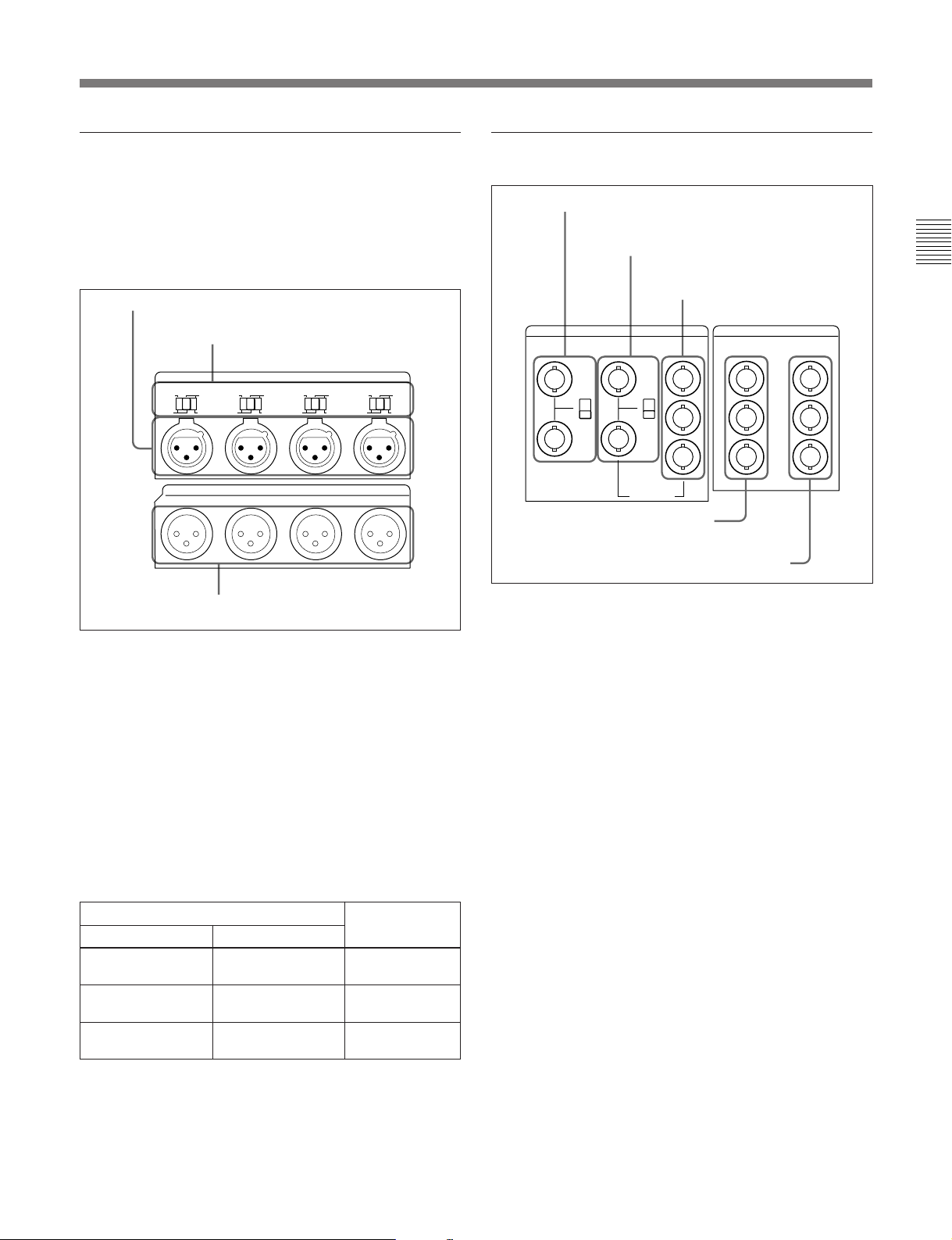
1 Analog (digital: option) audio input/
output section
2 Analog video input/output section
In the standard version this is an analog audio input/
output section. By means of an option, you can
replace it by AES/EBU digital audio inputs and
outputs.
1 AUDIO INPUT CH1 to CH4 connectors
2 AUDIO INPUT CH1 to CH4 LEVEL
switches
CH1
LEVEL
LOW HIGH
OFF ON
600Ω
CH1 CH2 CH3 CH4
AUDIO INPUT
CH2
LEVEL
LOW HIGH
OFF ON
AUDIO OUTPUT
600Ω
CH3
LEVEL
LOW HIGH
OFF ON
600Ω
CH4
LEVEL
LOW HIGH
OFF ON
600Ω
3 AUDIO OUTPUT CH1 to CH4
connectors
1 AUDIO INPUT CH1 to CH4 (channels 1 to 4)
connectors (XLR 3-pin, female)
Input analog audio signals to channels 1 to 4.
2 AUDIO INPUT CH1 to CH4 (channels 1 to 4)
LEVEL switches
Set these for each channel as shown in the following
table, according to the audio input levels to the
AUDIO INPUT CH1 to CH4 connectors and the
impedance.
AUDIO INPUT CH1 to CH4 LEVEL switch settings
Audio input level and impedance Switch setting
Level
–60 dBu
(microphone input)
+4 dBu
(line audio input)
+4 dBm
(line audio input)
Impedance
High impedance
(approx. 20 kΩ)
High impedance
(approx. 20 kΩ)
600 Ω
LOW-OFF
(left position)
HIGH-OFF
(center position)
HIGH-ON 600 Ω
(right position)
3 AUDIO OUTPUT CH1 to CH4 connectors
(XLR 3-pin, male)
These output analog audio signals for channels 1 to 4.
1 REF. VIDEO INPUT connectors and 75 Ω
termination switch
2 COMPOSITE VIDEO INPUT connectors
and 75 Ω termination switch
3 COMPONENT VIDEO INPUT
connectors
REF.VIDEO COMPOSITE COMPONENT
VIDEO INPUT VIDEO OUTPUT
(OPTION) (OPTION)
75Ω
ON
OFF
75Ω
ON
R-Y
OFF
B-Y
ALTERNATIVE
Y
COMPOSITE
1
2
3
(SUPER)
COMPONENT
(OPTION)
Y
R-Y
B-Y
4 COMPOSITE VIDEO OUTPUT
connectors
5 COMPONENT VIDEO OUTPUT connectors
1 REF. (reference) VIDEO INPUT connectors
(BNC type) and 75 Ω termination switch
Input a reference video signal. Input a video signal
with chroma burst (VBS) or a monochrome video
signal (VS). When using the loop-through connection
set the switch to the OFF position, and otherwise to the
ON position.
2 COMPOSITE VIDEO INPUT connectors (BNC
type) and 75 Ω termination switch
Input analog composite video signals.
When using the loop-through connection set the switch
to the OFF position, and otherwise to the ON position.
Of these and the COMPONENT VIDEO INPUT
connectors 3, only one set can be used, according to
an option.
To use these connectors requires the BKDW-505 (for
DNW-A100/A50/A45) or BKDW-506 (for DNWA100P/A50P/A45P) option.
3 COMPONENT VIDEO INPUT connectors
(BNC type)
Input analog component video signals (Y/R–Y/B–Y).
Of these and the COMPOSITE VIDEO INPUT
connectors 2, only one set can be used, according to
an option.
To use these connectors requires the BKDW-104
option.
Chapter 2 Location and Function of Parts
Chapter 2 Location and Function of Parts 2-23
Page 32
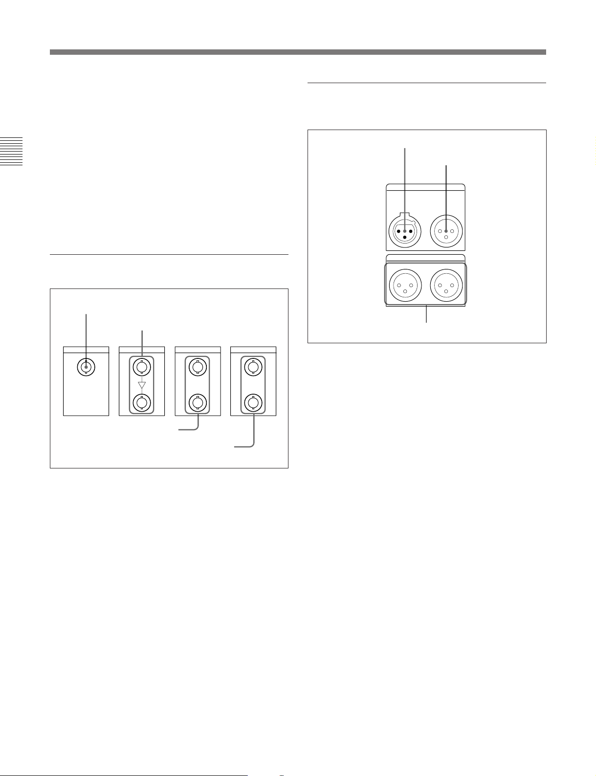
2-2 Connector Panel
TIME CODE
MONITOR OUTPUT
IN OUT
RL
4 COMPOSITE VIDEO OUTPUT connectors
(BNC type)
These output analog composite video signals.
When the CHARACTER switch on the subsidiary
control panel is set to ON, the output from connector 3
(SUPER) has superimposed text information such as
Chapter 2 Location and Function of Parts
time code, menu settings, and alarm messages.
5 COMPONENT VIDEO OUTPUT connectors
(BNC type)
These output analog component video signals (Y/R–Y/
B–Y).
3 Digital input/output section
1 SDDI DIGITAL INPUT connector (DNW-A100/A100P
only)
DIGITAL INPUT
(OPTION)
SDDI
2 SDI DIGITAL INPUT connectors
SDI SDDI SDI
1
2
DIGITAL OUTPUT
1
2
4 Time code input/output section and
audio monitor signal output section
1 TIME CODE IN connector
2 TIME CODE OUT
connector
3 MONITOR OUTPUT
connectors
1 TIME CODE IN connector (XLR 3-pin, female)
To record time code from an external device, input a
time code signal from the time code output connector
of the other device.
3 SDDI DIGITAL OUTPUT
connectors (DNW-A100/A100P only)
4 SDI DIGITAL OUTPUT connectors
1 SDDI (Serial Digital Data Interface) DIGITAL
INPUT connector (BNC type) (DNW-A100/A100P
only)
Input SDDI format digital video/audio signals. This
connector can only be used when the optional SDDI
input board is installed.
2 SDI (Serial Digital Interface) DIGITAL INPUT
connectors (BNC type)
Input D1 format digital video/audio signals. Of the
two connectors, the upper one is for input, and the
lower one is for a active-through connection.
3 SDDI (Serial Digital Data Interface) DIGITAL
OUTPUT connectors (BNC type) (DNW-A100/
A100P only)
These output SDDI format digital video/audio signals.
2 TIME CODE OUT connector (XLR 3-pin, male)
This outputs a time code according to the operating
state of the unit, as follows:
•During playback: the playback time code
By setting extended menu item 606, you can also
output the time code from the internal time code
generator locked to the playback time code..
•During recording: the time code generated by the
internal time code generator or the time code input to
the TIME CODE IN connector.
3 MONITOR OUTPUT connectors (XLR 3-pin,
male)
According to the setting of the AUDIO INPUT /
MONITOR SELECT buttons (Before Version 2.00) or
the AUDIO INPUT/MIXING/MONITOR SELECT
buttons (Version 2.00 or later) on the upper control
panel, two (L and R) audio monitor signals are output.
4 SDI (Serial Digital Interface) DIGITAL
OUTPUT connectors (BNC type)
These output D1 format digital video/audio signals.
2-24 Chapter 2 Location and Function of Parts
Page 33
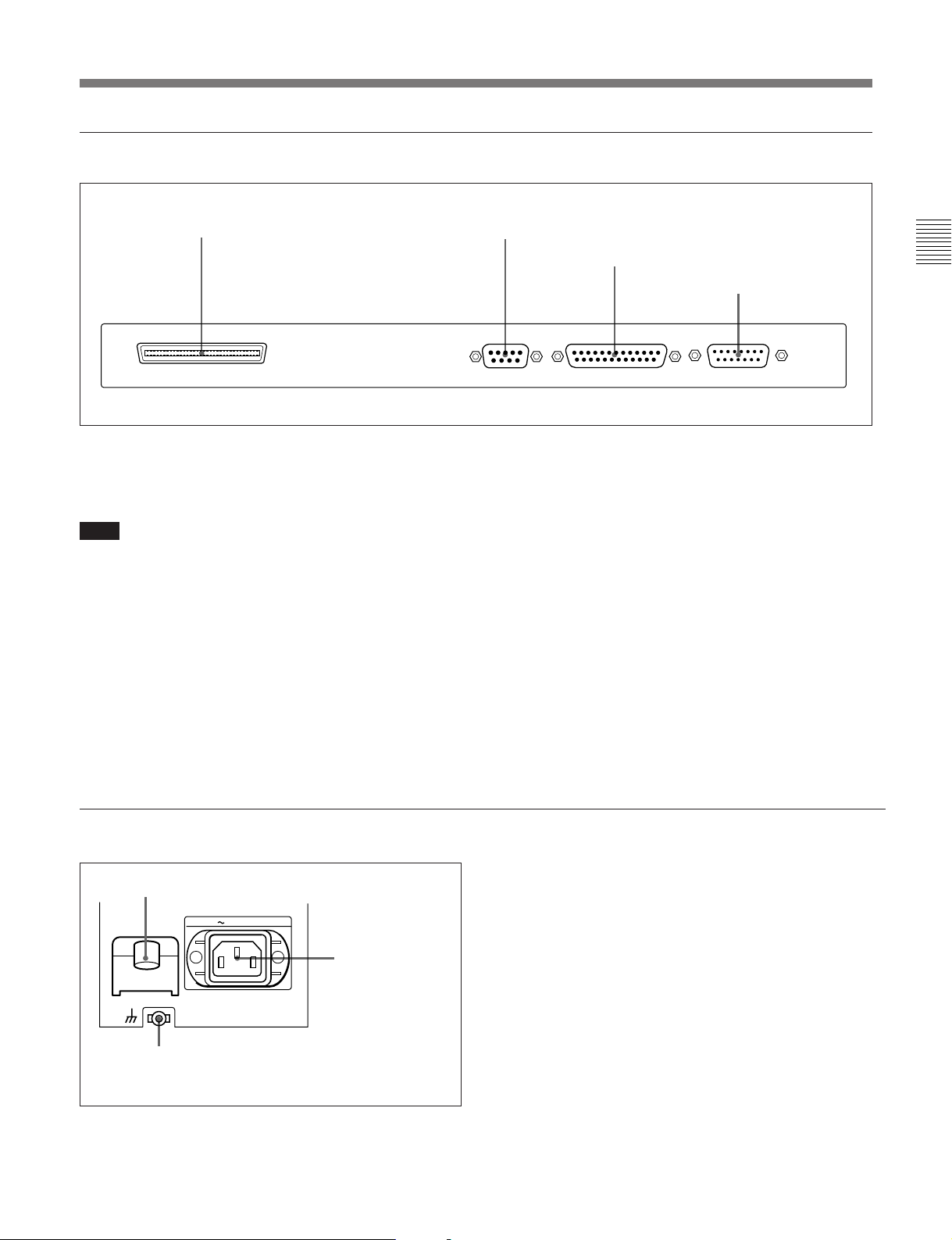
5 External device connectors
1 SCSI connector
SCSI REMOTE(9P) RS-232C VIDEO CONTROL
1 SCSI connector (68-pin)
Use this for connection to another device supporting
SCSI 2.
Note
If this connector is not used, be sure to attach a SCSI
terminator. If no SCSI terminator is attached, the hard
disk may malfunction.
2 REMOTE (9P) connector (D-subminiature 9pin)
For editing with two DNW-A100/A100P units, or with
another D-1, D-2, or Betacam VTR controlled by a
BVE-series editor such as a BVE-900/910/2000/9000/
9000P/9100/9100P, use a 9-pin remote control cable
for connection to the other device.
2 REMOTE (9P) connector
3 RS-232C connector
4 VIDEO CONTROL
connector
3 RS-232C connector (D-subminiature 25-pin)
Use this for monitoring and diagnosis of the state of
this unit from an external computer, using ISR
(Interactive Status Reporting).
4 VIDEO CONTROL connector (D-subminiature
15-pin)
For remote control of the internal digital video
processor, connect an optional BVR-50/50P Remote
Control Unit or similar.
Always power off this unit before connecting the
remote control unit.
Chapter 2 Location and Function of Parts
6 Power supply section
2 BREAKER button
BREAKER
3 Ground terminal
AC IN
1 AC IN connector
1 AC IN connector
Use the supplied power cord to connect this to an AC
outlet.
2 BREAKER button
This jumps out if an excess current flows on the
primary side of the AC power circuit.
3 Ground terminal
Connect this to ground.
Chapter 2 Location and Function of Parts 2-25
Page 34

Page 35
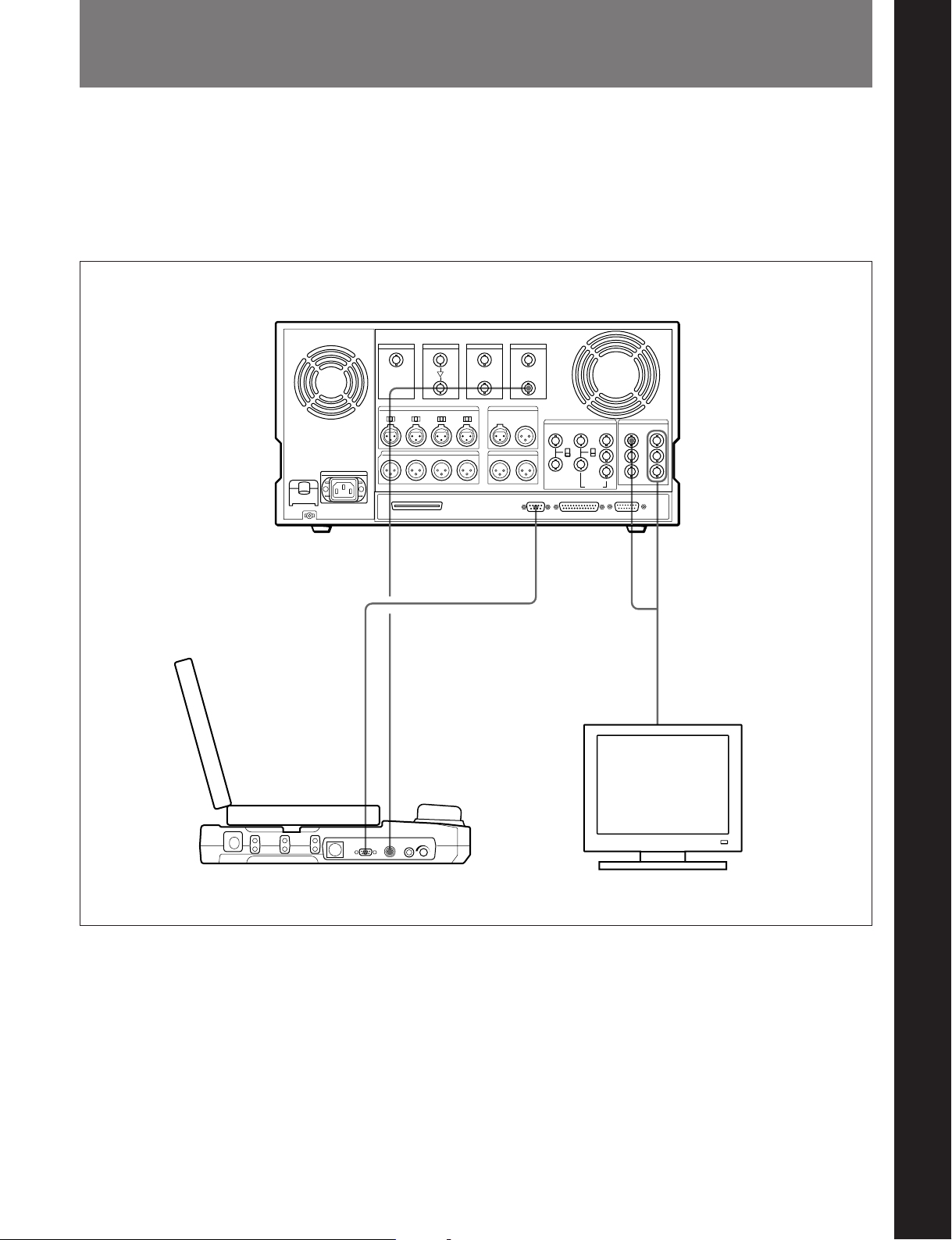
3-1 Connections to External Devices
This section gives examples of how to connect an
external editor to the unit, or how to use the unit
connected to an analog device such as a Betacam SP
VTR.
•Connection to a DNE-50/50P external editor
DNW-A100/A100P
Chapter 3 Preparations
Chapter 3 Preparations
DNE-50/50P
SDI DIGITAL
OUTPUT
REMOTE (9P) SDI IN
REMOTE (9P) COMPONENT or
COMPOSITE VIDEO
OUTPUT
Video monitor
Chapter 3 Preparations 3-1
Page 36
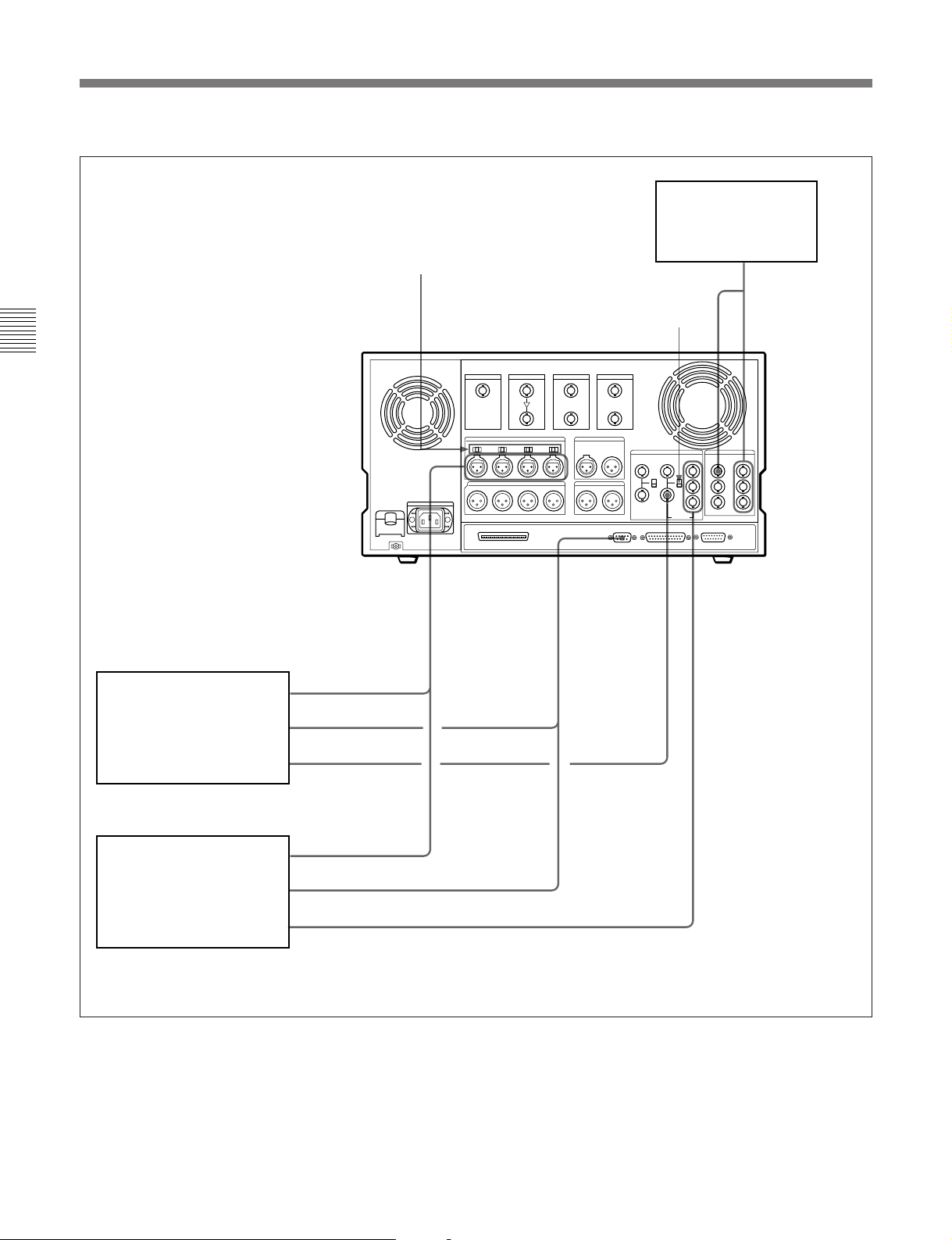
3-1 Connections to External Devices
•Connection to an analog device
Chapter 3 Preparations
AUDIO INPUT CH1 to CH4 LEVEL switches:
set according to the analog input level
and the impedance. (See page 2-23.)
DNW-A100/A100P/A50/
A50P/A45/A45P, DVR-28/
28P/20/20P D2 VTR, BVH3000/3000PS or other 1-inch
VTR (player)
a)
DNW-A100/
A100P
AUDIO
INPUT CH1
to CH4
AUDIO OUTPUT CH1
to CH4 (analog)
REMOTE (9P)
VIDEO OUTPUT
(composite)
75 Ω termination switch:
set to OFF when using an analog
composite video signal bridge
connection, and otherwise to ON.
REMOTE (9P) COMPOSITE
VIDEO INPUT
Video monitor
COMPONENT
or COMPOSITE
VIDEO
OUTPUT
COMPONENT
VIDEO INPUT
BVW-75/70/65/60 series
Betacam SP VTR
a)
(player)
a) You cannot connect more than one external device as the player to the unit.
AUDIO OUTPUT CH1 to CH4 (analog)
REMOTE (9P)
VIDEO OUTPUT (component)
3-2 Chapter 3 Preparations
Page 37
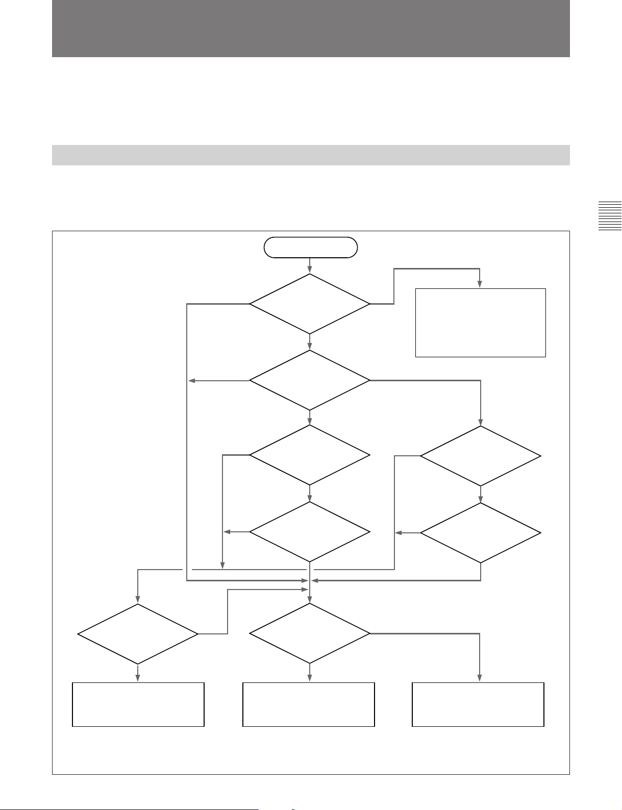
3-2 Reference Signals for Video Output and Servo System
This section describes how reference signals for the
video output signals and servo system are selected.
The output from the internal reference video signal
generator is supplied to the output video signal and
servo circuits as a reference signal.
3-2-1 External Sync Signal for the Internal Reference Video Signal Generator
The internal reference video signal generator is
synchronized either to a reference video signal or to an
input video signal. Depending on the settings of the
Other than tape
only or hard disk
a)
only
specification?
EXT AUTO1
Setting of extended
menu item 309?
OUT REF switch on the subsidiary control panel and
extended menu item 309, and the input signal
selection, the external synchronization status is as
shown in the following flowchart.
Start
Device
Recorder
hard disk
only
Recorder tape
only
The internal reference video
signal is the signal selected
according to the flowchart in
Section 3-2-2 “Reference Signal
for the Server System”.
Chapter 3 Preparations
Is a signal input to
the connector selected
with the VIDEO INPUT
SELECT switch?
Yes
Synchronize to the input video
signal selected with the VIDEO
INPUT SELECT switch.
No
INPUT
VIDEO
Yes
Setting of the OUT
REF switch?
Currently recording
or editingc)?
Is a signal input to
the REF. VIDEO
INPUT connector?
Synchronize to the reference
video signal input to the REF.
VIDEO INPUT connector.
AUTO2
REF
No
Yes
INPUT
VIDEO
b)
Yes
No
Setting of the OUT
REF switch?
REF
Currently recordingb)?
No
No external synchronization.
a) VTR or hard disk only operation, with an external device (EXT) specified as the player regardless of what device is specified as the recorder.
b) Currently recording: status in which recording on tape or the hard disk is being carried out regardless of what device is specified as the recorder.
c) Currently editing: status in which buttons in the editing mode setting section have been set for assemble or insert editing.
Chapter 3 Preparations 3-3
Page 38
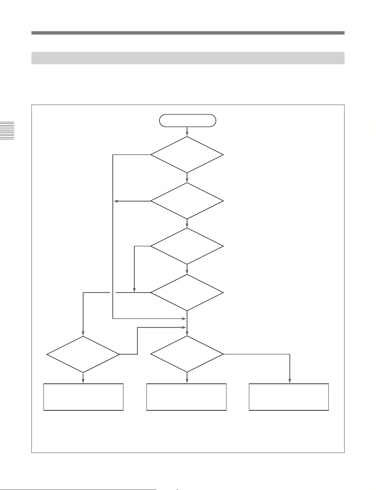
3-2 Reference Signals for Video Output and Servo System
3-2 Reference Signals for Video Output and Servo System
3-2-2 Reference Signal for the Servo System
The VTR automatically selects either the input video
signal or the output from the internal reference video
signal generator as the reference signal for the servo
Chapter 3 Preparations
No
EXT
INPUT
VIDEO
system. Which of the two signals is selected depends
on the operational status of the VTR, as shown in the
following flowchart.
Start
VTR or hard disk only
operationa)?
Yes
Setting of extended
menu item 309?
AUTO1
AUTO2
Setting of the OUT
REF switch?
REF
Yes
Is a signal input to
the commector selected
with the VIDEO INPUT
SELECT switch?
Yes
Lock the servo to the input
video signal selected with the
VIDEO INPUT SELECT switch.
a) VTR or hard disk only operation, with an external device (EXT) specified as the player regardless of what
device is specified as the recorder.
b) Currently recording: status in which recording on tape or the hard disk is being carried out regardless of what
device is specified as the recorder.
c) Currently editing: status in which buttons in the editing mode setting section have been set for assemble or
insert editing.
No
Synchronize to the reference
video signal input to the REF.
VIDEO INPUT connector.
Currently
recordingb) or
editingc)?
No
Is a signal input to
the REF. VIDEO
INPUT connector?
Yes
No
Internal synchronization.
3-4 Chapter 3 Preparations
Page 39
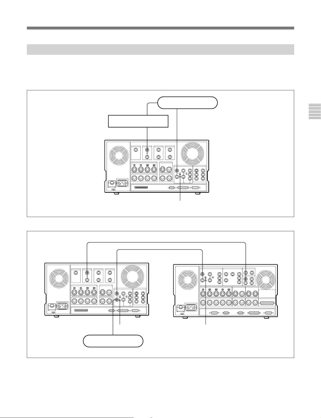
3-2-3 Connecting Reference Signals
Connect reference signals as shown below, according
to the way in which the unit is to be used.
•Connections for recording from a switcher or signal generator
Reference signal
Switcher or signal generator
SDI DIGITAL INPUT REF. VIDEO INPUT
DNW-A100/A100P
75 Ω termination switch: ON
•Connections for recording from an external VTR (player)
SDI DIGITAL INPUT
REF. VIDEO
INPUT
Chapter 3 Preparations
SERIAL V/A
OUTPUT
DNW-A100/
A100P
(recorder)
REF. VIDEO
INPUT
Reference signal
75 Ω termination switch: OFF
75 Ω termination switch: ON
DVW-A510/A510P/
510/510P series
(player)
Chapter 3 Preparations 3-5
Page 40
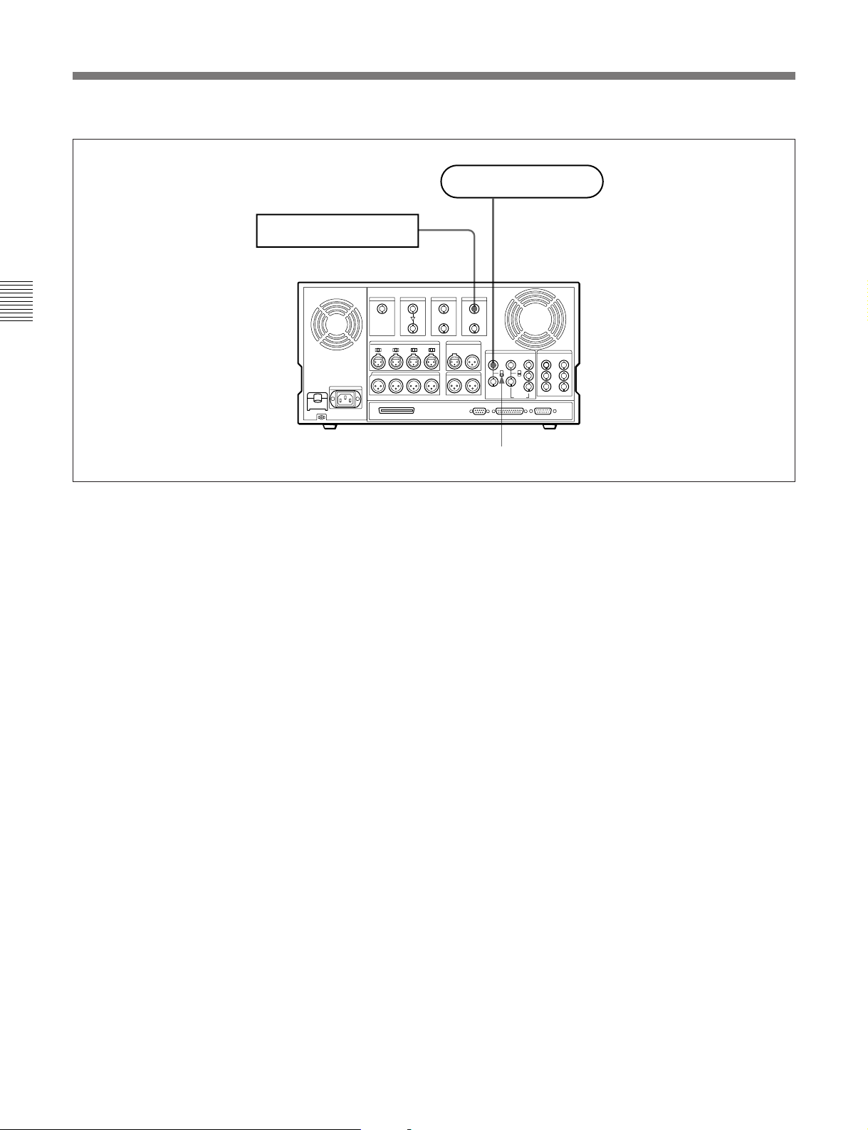
3-2 Reference Signals for Video Output and Servo System
•Connections for playback
Chapter 3 Preparations
Reference signal
Serial monitor
SDI DIGITAL OUTPUT REF. VIDEO INPUT
DNW-A100/A100P
75 Ω termination switch: ON
3-6 Chapter 3 Preparations
Page 41

3-3 Setup
The principal setup operations before operating this
unit can be carried out using setup menus.
The setup menus of this unit comprise a basic menu,
an extended menu, and a disk file management menu.
The contents of these menus are as follows.
Basic menu:
•Items relating to the hours meter
•Items relating to operation
•Items relating to menu banks
Extended menu:
•Items relating to the control panels
•Items relating to the remote control interface
• Items relating to editing operations
•Items relating to preroll
•Items relating to tape protection
•Items relating to the time code generator
•Items relating to video control
•Items relating to audio control
•Items relating to digital processing
Disk file management menu:
Items relating to the creation and management of files
on the built-in hard disk.
For detailed information about the items, except for the
basic menu items relating to the hours meter, of these menus
and how to use them, see Chapter 7, “Menu System”.
For details of the basic menu items relating to the hours
meter, see Section 8-5, “Digital Hours Meter” (page 8-3).
This unit allows four different sets of menu settings to
be saved in what are termed “menu banks” numbered 1
to 4. Saved sets of menu settings can be recalled for
use as required.
Chapter 3 Preparations
For more information about the menu banks, see the section
“Menu bank operations (menu items B01 to B14)” (page
7-8) .
Chapter 3 Preparations 3-7
Page 42
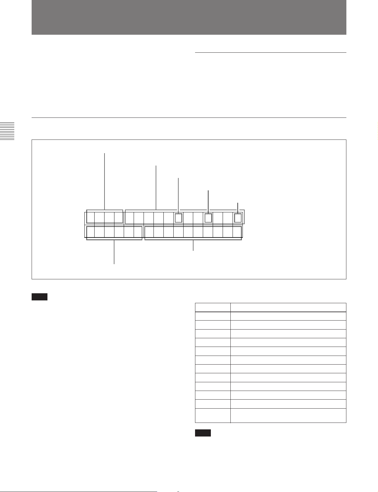
3-4 Superimposed Character Information
3-4 Superimposed Character Information
When the CHARACTER switch on the subsidiary
control panel is set to ON, the video signal output from
the COMPOSITE VIDEO OUTPUT 3 (SUPER)
connector contains superimposed character
information, including time code, menu settings, and
alarm messages.
Information displayed
Chapter 3 Preparations
Adjusting the character display
You can adjust the position, size and type of the
superimposed characters using the basic menu.
For details of the basic menu, see Section 7-2, “Basic
Menu” (page 7-1).
1 Types of time data
Time data
2 Drop frame mode of time code reader (for 525
mode only)
3 Drop frame mode of time code
generator (for 525 mode only)
4 VITC field
TCR. 23 : 59 . 40 . 18*
[TP ] SHTL STILL
5 Device selection
Note
The display shown above corresponds to the factory
default settings of the unit.
Changing the setting of basic menu item 005 allows
different time data to be displayed in the bottom line of
the display.
For details of basic menu item 005, see Section 7-2-1,
“Items in the Basic Menu” (page 7-1).
6 Operation mode
1 Types of time data
Display Meaning
CTL CTL counter data
TCR LTC reader time code
UBR LTC reader user’s bits
TCR. VITC reader time code
UBR. VITC reader user’s bits
TCG Time code generator time code
UBG Time code generator user’s bits
IN IN point
OUT OUT point
AI Audio IN point
AO Audio OUT point
DUR Duration between any two of the four edit
points (IN, OUT, audio IN, audio OUT)
3-8 Chapter 3 Preparations
Note
If the time data or user’s bits cannot be read correctly,
they will be displayed with an asterisk. For example,
“T*R”, “U*R”, “T*R.” or “U*R.”.
Page 43
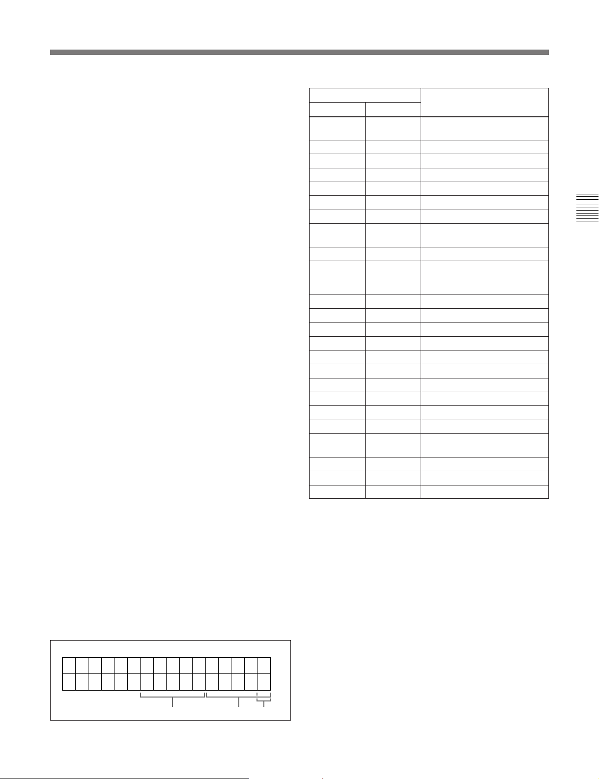
2 Drop frame mode for time code reader (for 525
mode only)
“.”: Drop frame mode
“:”: Non-drop-frame mode
3 Drop frame mode for time code generator (for
525 mode only)
“.”: Drop frame mode (factory preset)
“:”: Non-drop-frame mode
4 VITC field
“ ” (blank): Fields 1 and 3
“*”: Fields 2 and 4
5 Device selection
Indication of the device selected on the control panel.
This is displayed in one of the following three formats
depending on the unit’s status.
•[device name indication]: SELF mode
(RECORDER button and PLAYER button both unlit)
or 9-pin remote control mode (9P indicator lit)
•P [device name indication]: Player mode (PLAYER
button lit)
•R [device name indication]: Recorder mode
(RECORDER button lit)
The device name indications used for this display are
as follows.
EXT: EXT
TP: TAPE
MST: DISK MASTER
PGM: DISK PROGRAM
D.P: DISK PLAYER PORT (hard disk playback
being carried out through 9-pin remote control)
D.R: DISK RECORDER PORT (hard disk recording
being carried out through 9-pin remote control)
Display
Block A Block B
TAPE
UNTHD
STDBY OFF Standby off mode
T.RELEASE Tape tension released
STOP Stop mode
F.FWD Fast forward mode
REW Rewind mode
PREROLL Preroll mode
PLAY Playback mode (servo
PLAY Playback mode (servo locked)LOCK
PLAY Deviation
from normal
speed (%)
REC Record mode (servo unocked)
REC LOCK Record mode (servo locked)
EDIT Edit mode (servo unlocked)
EDIT LOCK Edit mode (servo locked)
JOG STILL A still picture in jog mode
JOG FWD Jog mode in forward direction
JOG REV Jog mode in reverse direction
SHTL (Speed) Shuttle mode
VAR (Speed) Variable mode
FEED (Speed) Feed play mode
SPD (Speed) Initial speed setting for feed
PREVIEW Preview mode
AUTO EDIT Automatic editing mode
REVIEW Review mode
Operation mode
Cassette is not loaded.
unlocked)
Capstan override mode
play
Chapter 3 Preparations
6 Operation mode
The field is divided into three blocks, A, B and C.
•Block A displays the operation mode.
•Block B displays the servo lock status or tape speed.
•Block C displays a p mark to indicate an edit section
during automatic editing.
A
BC
Chapter 3 Preparations 3-9
Page 44
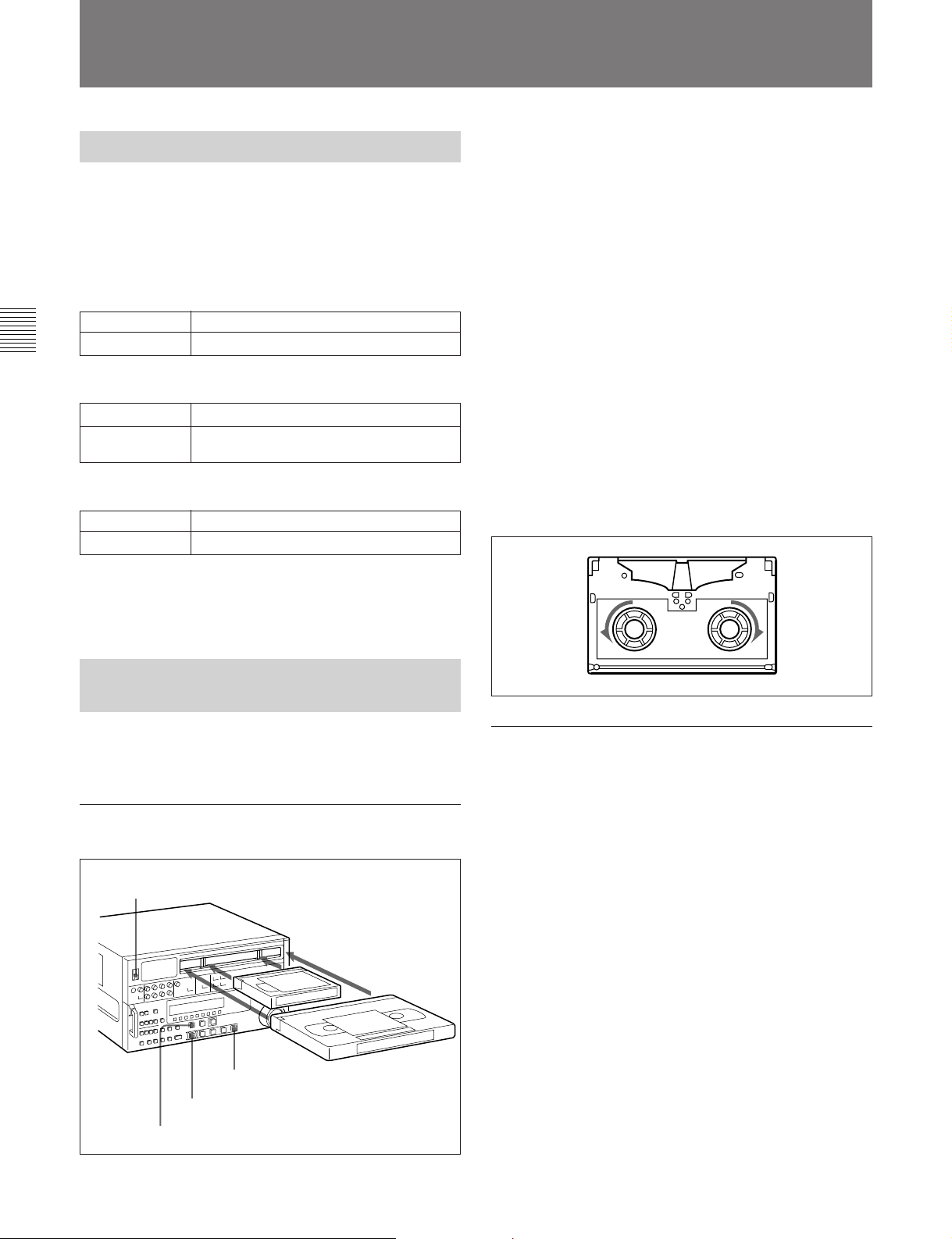
3-5 Cassettes
3-5 Cassettes
This unit uses a 1/2-inch tape width for both recording
and playback. You can use Betacam SX cassettes,
Betacam SP cassettes (metal tape), or UVW cassettes
(metal tape).
Chapter 3 Preparations
The oxide tapes recorded in Betacam format can be
used for playback only.
3-5-1 Cassette Types
Betacam SX cassettes
Small cassettes BCT-12SX/22SX/32SX/60SX
Large cassettes BCT-64SXL/94SXL/124SXL/184SXL
Betacam SP cassettes (metal tape)
Small cassettes
Large cassettes BCT-5MLA/10MLA/20MLA/30MLA/60MLA/
Small cassettes UVWT-10MA/20MA/30MA
Large cassettes UVWT-60MLA/90MLA
BCT-5MA/10MA/20MA/30MA
90MLA
UVW cassettes (metal tape)
1 Turn the POWER switch on.
2 Check the following points, before inserting the
cassette in the orientation shown in the figure.
•Check that message “ERROR-10” is not shown in
the time data display area 1.
•Check that there is no slack in the tape.
The cassette is drawn into the unit, and the
STANDBY and STOP buttons light.
If message “ERROR-10” appears in the time data display
area 1 , there is moisture condensation in the unit. For steps
to take when “ERROR-10” is displayed, see Section 8-4,
“Moisture Condensation” (page 8-2).
Removing slack from the tape
Press in one of the reels with a finger, and turn gently
in the direction shown by the arrows until there is no
slack in the tape.
3-5-2 Inserting and Ejecting
Cassettes
It is not possible to insert or eject a cassette unless the
unit is powered on.
Inserting a cassette
1
2
Small
cassette
STOP button
EJECT button
STANDBY button
Large cassette
Ejecting a cassette
Press the EJECT button.
If the tape slacks inside the unit, pressing the EJECT button
may not eject the cassette. For information about how to
remove the cassette in such a case, refer to the Maintenance
Manual.
3-10 Chapter 3 Preparations
Page 45
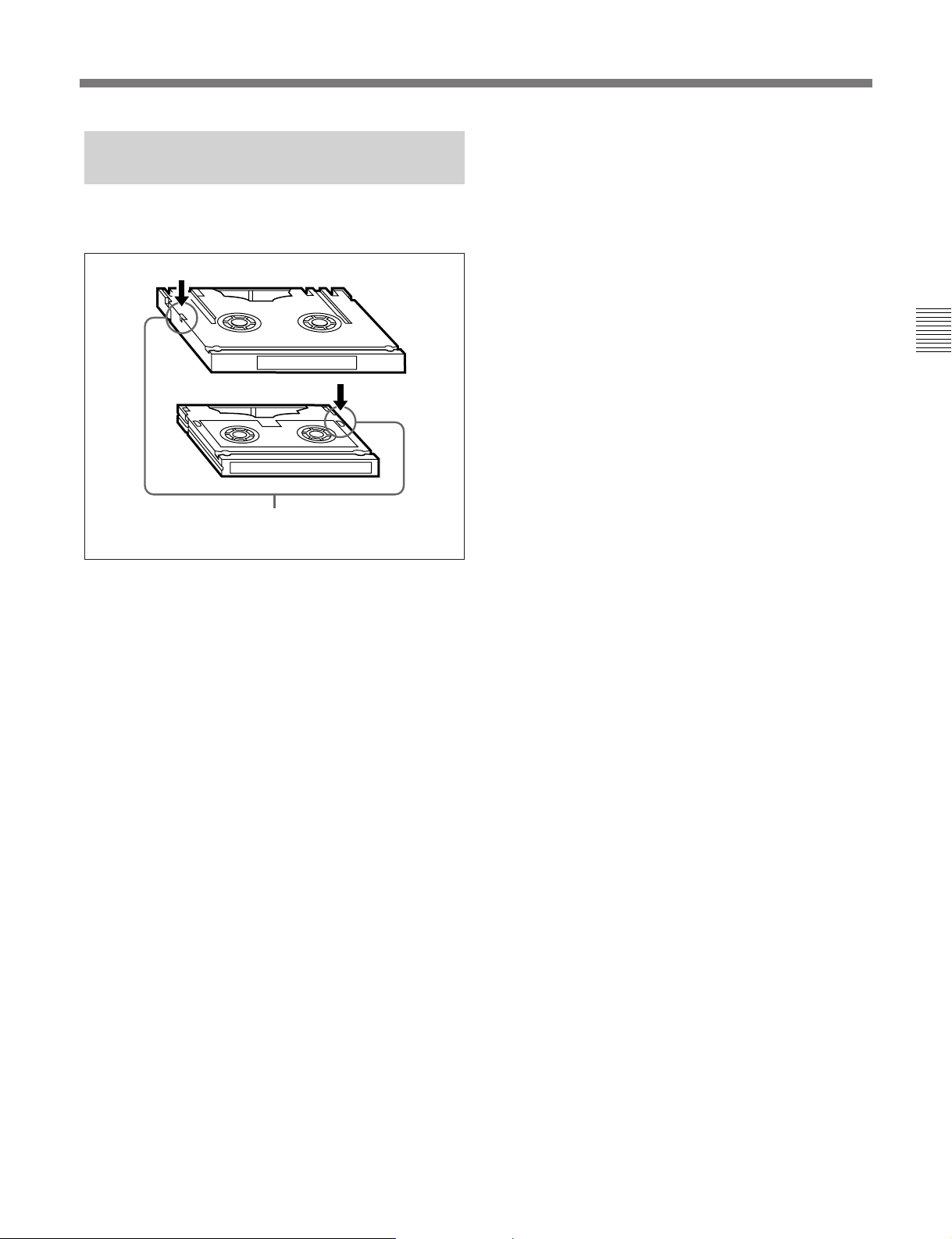
3-5-3 Preventing Accidental
Erasure of Recordings
To prevent a tape from being inadvertently erased,
press in the red erase-protect plug on the cassette.
Large cassette
Small cassette
Press in the red erase-protect plug. (“ON”)
Return this plug to its original position to enable recording on the
tape again. (“OFF”)
Chapter 3 Preparations
Chapter 3 Preparations 3-11
Page 46

Page 47

4-1 Recording
This section describes recording on the VTR and hard
disk built into the unit.
4-1-1 Preparations for Recording
Chapter 4 Recording and Playback
Switch settings
Before beginning recording, make any necessary
switch settings.
VIDEO INPUT SELECT switch
(see page 2-3): select the input
video signal
POWER switch: ON
For details of the settings of each of the switches, refer to
the pages indicated in parenthesis.
Audio selection function selector switch (see page 2-3):
select the input audio signal
AUDIO INPUT/MONITOR SELECT buttons (Before Version 2.00)
AUDIO INPUT/MIXING/MONITOR SELECT buttons (Version 2.00
or later) (see page 2-4): select the audio channel(s) to be monitored
REMOTE/LOCAL switch (see page 2-7):
9P indicator off
Chapter 4 Recording and Playback
REC controls (see page 2-3):
adjust the audio recording
levels (see page 4-2)
PB.EE button (see page 2-9): lit
REC INHIBIT switch (see page 2-21): OFF
Device specification buttons (see page 2-12):
select the device on which operations are to
be carried out (see page 4-2)
CTL/TC/UB button (see page 2-9): select
the time data to be displayed
Chapter 4 Recording and Playback 4-1
Page 48
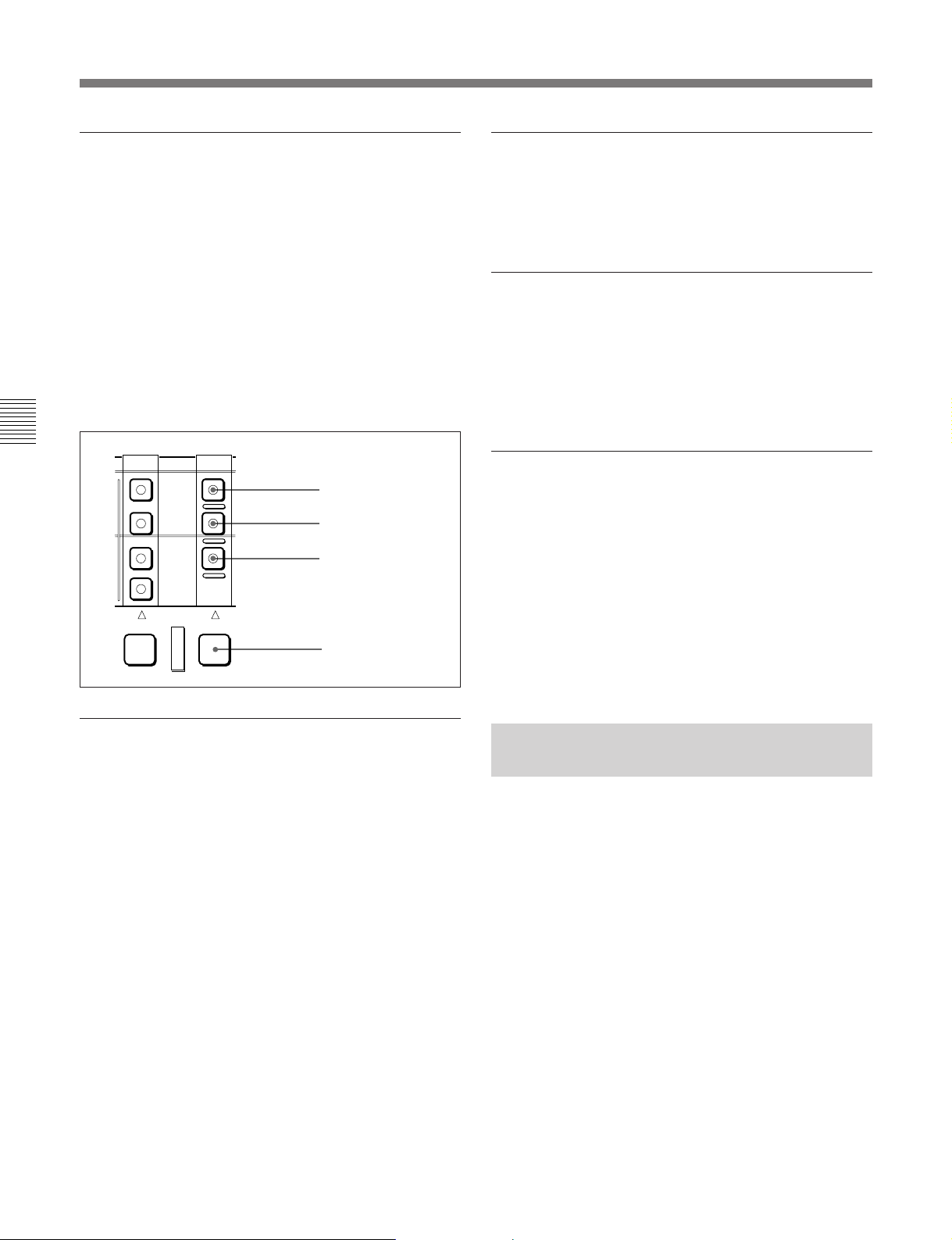
4-1 Recording
Selecting the device on which operations
are to be carried out
Carry out one of the following operations depending
on which of the built-in VTR or hard disk is subject to
operations.
•To carry out operations on the built-in VTR
Hold down the RECORDER button, and press the
TAPE button in the RECORDER row, turning it on.
• To carry out operations on the hard disk
Hold down the RECORDER button, and press the
DISK PROGRAM or DISK MASTER button in the
RECORDER row, turning it on.
Chapter 4 Recording and Playback
PLAYER RECORDER
DISK
PRORRAM
DISK
MASTER
TAPE
EXT
DISK
PROGRAM button
DISK
MASTER button
TAPE button
RECORDER button
To change the display range of the audio
level indications
Press the DISPLAY FULL/FINE switch (see page 2-
5).
To monitor the simultaneous playback of
the recorded video and audio signals
Make a setting with extended menu item 316 to enable
the CONFI playback function.
For details, see section 7-3, “Extended Menu” (page 7-9).
To use the emphasis function
To add emphasis to the analog input audio signal or
analog playback audio signal, set the EMPHASIS
switch on the subsidiary control panel to the ON
position.
When the signal to which emphasis has been applied is
played back, it is automatically subjected to
deemphasis processing.
Using the emphasis-deemphasis processing enables the
dynamic range to be improved by reducing highfrequency noise.
Adjusting the audio recording levels
When carrying out audio recording at a
reference level
Leave the REC controls pressed in. The audio signals
will be recorded at a preset reference level (a reference
0 dB indication for an input of +4 dBm).
Manually adjusting the recording levels
For each channel, pull out the REC control in the
upper control panel, and adjust so that the audio level
indication is 0 dB for an average volume. Carry out
the adjustment in E-E mode.
For details of selecting the E-E mode, see the description of
the REC button in the tape/disk transport control section
(page 2-16) and the PB.EE button in the monitor/menu/
display setting section (page 2-9).
4-1-2 Recording Time Code and
User Bit Values
There are three ways of recording time code, as
follows:
•Setting an initial value, then recording the output of
the internal time code generator
•Recording the output of the internal time code
generator synchronized to an external time code
generator
•Recording an external time code without
modification
4-2 Chapter 4 Recording and Playback
Page 49
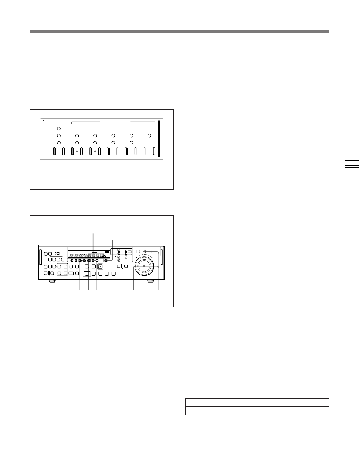
To set an initial value then record the time
code
flashing digit position to the right, and turning the
search dial counterclockwise moves the flashing
digit position to the left.
If necessary, change the settings in the time code
setting section (see page 2-6).
Set the INT/EXT switch to INT, and the PRESET/
REGEN switch to PRESET.
TC GENERATOR
FREE
RUN
REGEN
REC
RUN
PRESET/REGEN switch: PRESET
NDF
DF
ON
VITC
LTC
AUTO
VITC
TC
INT
PRESET
EXT
INT/EXT switch: INT
To set an initial time code value
Use the following procedure.
Time data display area 2
RESET button
4 Hold down the JOG button, then turn the search
dial to change the value in the flashing digit
position.
5 Until all the digits are set as required, repeat steps
3 and 4.
6 Press the SET button.
The HOLD button goes off.
When the FREE RUN/REC RUN switch is set to
FREE RUN, the time code value immediately
starts advancing.
To set the time code value to the real time
With the switches in the time code setting section set
as follows, carry out the procedure under the heading
above, “To set an initial time code value.” In steps 4
and 5, set the value slightly after the current time, then
carry out step 6 at the instant the real time catches up
with the setting.
INT/EXT switch: INT
PRESET/REGEN switch: PRESET
FREE RUN/REC RUN switch: FREE RUN
DF/NDF switch: DF
Chapter 4 Recording and Playback
12634
1 Set the CTL/TC/UB switch to TC.
2 Press the HOLD button.
The button lights, and in the time data display area
2, the first digit of the value (8 digits: hours,
minutes, seconds, and frames) begins to flash.
To set all digits to zero
Press the RESET button.
3 Turn the search dial to select the digit to be
changed.
Turning the search dial clockwise moves the
Setting a user bit value
The user bit values recorded on the time code track
provide for eight hexadecimal digits, which can be
used to hold the date, time, event number or other
information.
Use the following procedure.
1 Set the CTL/TC/UB switch to UB.
2 Carry out the procedure in steps 2 to 6 under the
heading above, “To set an initial time code value.”
You can set each digit to any hexadecimal value,
represented by 0 to 9, and A to F. Hexadecimal
digits A to F appear in the seven-segment display
as follows.
Digit A B C D E F
Display AbCdEF
Chapter 4 Recording and Playback 4-3
Page 50
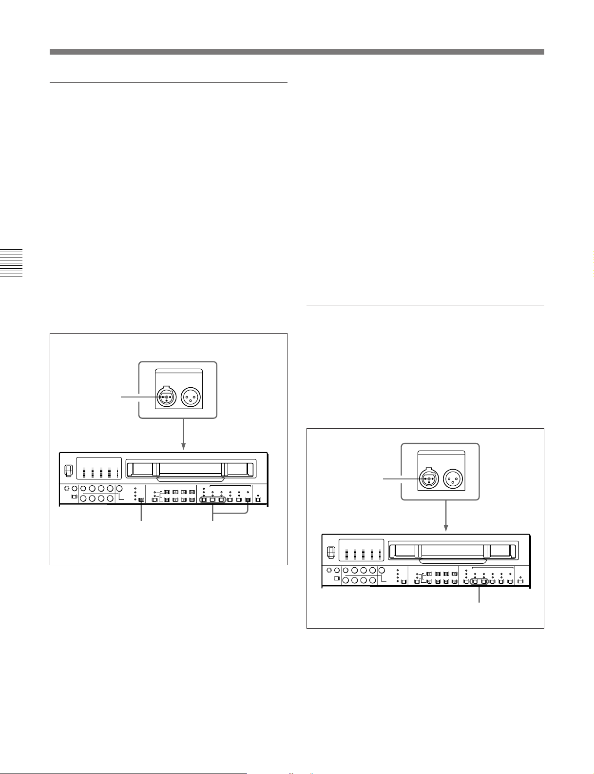
4-1 Recording
To synchronize the internal time code
generator to an external signal
Use this method to synchronize the time code
generators of a number of VTRs, or to record the
playback time code signal from an external VTR
without deterioration of the signal waveform.
In this case the settings of the FREE RUN/REC RUN
switch and DF/NDF switch are ignored.
You can synchronize the internal time code generator
to either of the following external time codes.
•The time code output (LTC) of an external time code
generator or external VTR connected to the TIME
CODE IN connector of the unit
•The time code (VITC) present in a video signal input
Chapter 4 Recording and Playback
to the unit
To synchronize the internal time code generator to an
external signal, use the following procedure.
TIME CODE IN connector
IN OUT
1
TIME CODE
2 Set the switches as follows:
INT/EXT switch: EXT
PRESET/REGEN switch: REGEN
VITC switch: ON (when recording VITC)
TC switch: LTC or VITC according as you are
synchronizing to LTC or VITC (If set to
AUTO, LTC is used.)
This starts the internal time code generator running
in synchronization with the external time code
generator.
Once the internal time code generator is
synchronized with the external time code
generator, even if the external time code generator
connection is removed, the internal time code
generator continues to run.
To record an external time code without
modification
Using this method has no effect on the running of the
internal time code generator.
To record the playback time code from an external
VTR, the method under the heading above, “To
synchronize the internal time code generator to an
external signal,” is recommended.
12
(VIDEO INPUT
SELECT
switch)
1 • When synchronizing to an external time code
output (LTC)
Connect the time code output of the external time
code generator or external VTR to the TIME
CODE IN connector.
•When synchronizing to the time code (VITC) in
an input video signal
With the VIDEO INPUT SELECT switch, select
an input video signal containing VITC.
TIME CODE
IN OUT
1
2
1 Connect the time code output of the external time
code generator to the TIME CODE IN connector.
2 Set the switches as follows:
INT/EXT switch: EXT
PRESET/REGEN switch: PRESET
4-4 Chapter 4 Recording and Playback
Page 51
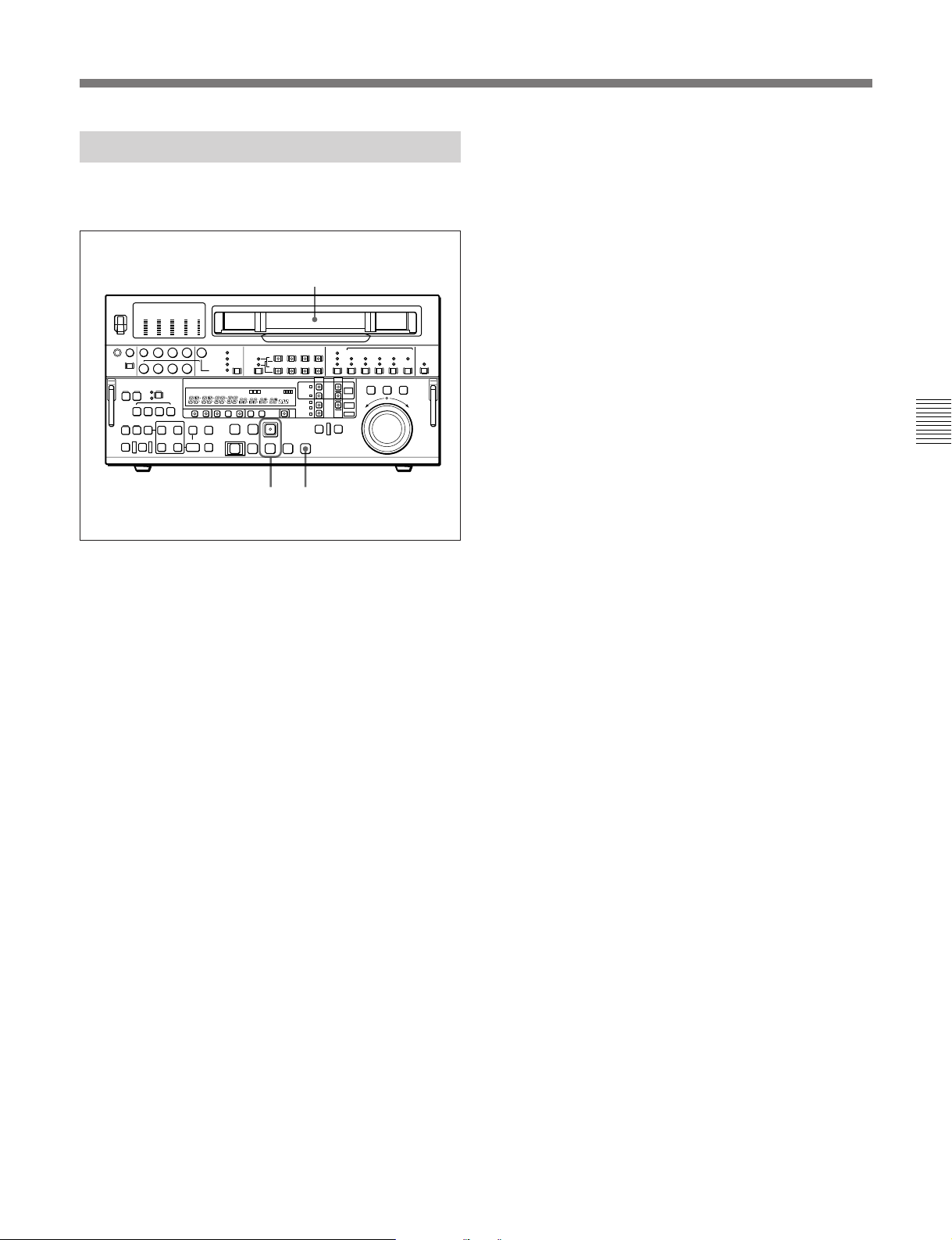
4-1-3 Recording Procedure
If you record to the end of the tape
The tape is automatically rewound, and stops.
To record, use the following procedure.
1
23
1 When the device subject to operations is TAPE,
insert a cassette.
For details, see the section “Inserting a cassette” (page
3-10).
If you record to the end of the hard disk
The hard disk stops after automatically returning to the
position where recording was started.
Chapter 4 Recording and Playback
2 Hold down the REC button, and press the PLAY
button.
•When TAPE is the device subject to operations
Recording starts, the servo locks, and the SERVO
indicator lights.
•When MASTER is the device subject to
operations
Recording starts and the TOTAL/REMAIN time
display changes with the progress of recording.
When PROGRAM is the device subject to
operations, you cannot carry out recording by
pressing the REC button and the PLAY button.
3 To stop recording, press the STOP button.
When MASTER is the device subject to
operations, the hard disk stops after automatically
returning to the position where recording was
started.
Chapter 4 Recording and Playback 4-5
Page 52
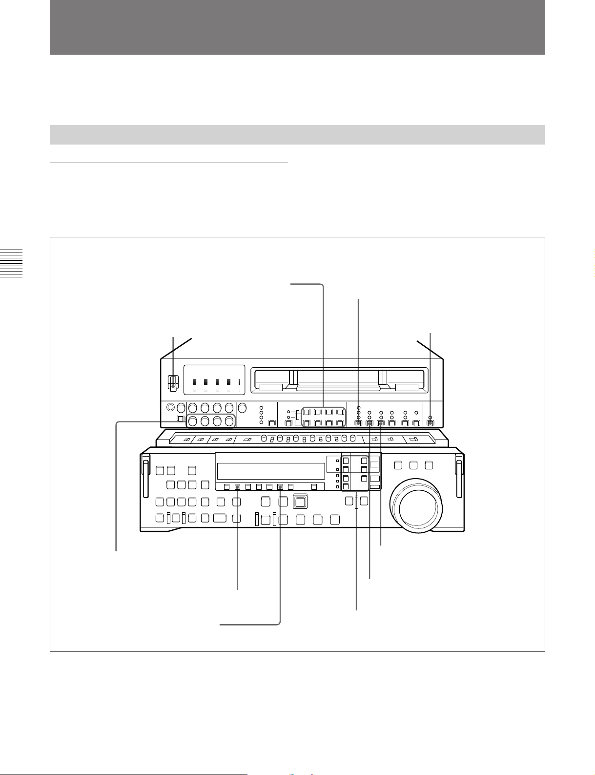
4-2 Playback
4-2 Playback
This section describes playback from the VTR and
hard disk built into the unit.
4-2-1 Preparations for Playback
Switch settings
Before beginning playback, make any necessary
switch settings.
Chapter 4 Recording and Playback
AUDIO INPUT/MONITOR SELECT buttons (Before
Version 2.00)
AUDIO INPUT/MIXING/MONITOR SELECT buttons
(Version 2.00 or later) (see page 2-4): select the audio
channel(s) to be monitored
POWER switch: ON
For details of the settings of each of the switches, refer to
the pages indicated in parenthesis.
TC switch (see page 2-6):
select the time code to be
displayed
REMOTE/LOCAL switch (see page 2-7):
9P indicator off
PB controls (see page 2-5):
adjust the audio playback
levels
PB button (see page 2-9): lit
CTL/TC/UB button (see page 2-9 ):
select the time data to be displayed
4-6 Chapter 4 Recording and Playback
PRESET/REGEN switch (see page 2-6):
select the output time code
INT/EXT switch (see page 2-6): INT
Device specification buttons (see page 2-12):
selecting the device on which operations are
to be carried out (see page 4-2)
Page 53
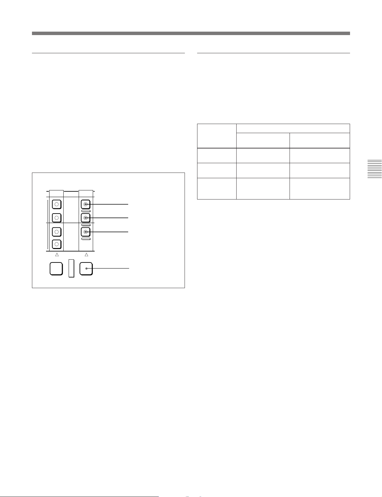
Selecting the device on which operations
are to be carried out
Carry out one of the following operations depending
on which of the built-in VTR or hard disk is subject to
operations.
•To carry out operations on the built-in VTR
Hold down the RECORDER button, and press the
TAPE button in the RECORDER row, turning it on.
•To carry out operations on the hard disk
Hold down the RECORDER button, and press the
DISK PROGRAM or DISK MASTER button in the
RECORDER row, turning it on.
DISK
PRORRAM
DISK
MASTER
TAPE
EXT
DISK
PROGRAM button
DISK
MASTER button
TAPE button
Time data selection
Displayed time data
Use the CTL/TC/UB button to select one of CTL
(control), time code, and user bit values. When you
select time code, the data displayed is determined by
the setting (LTC/AUTO/VITC) of the TC switch as
follows.
TC switch
setting
LTC LTC recorded on
VITC VITC recorded on
AUTO LTC or VITC
a) • When playing back DISK MASTER: Continuous time
code beginning with the time code value of the hard
disk position where the recorded file starts.
• When playing back DISK PROGRAM: Continuous
time code beginning with time code value 0 assigned to
the beginning of the program.
Displayed data
When playing
back tape
tape
tape
(automatically
switched)
When playing back
hard disk
LTC recorded on hard
disk
VITC recorded on
hard disk
Virtual file time code
a)
Chapter 4 Recording and Playback
PLAYER RECORDER
RECORDER button
Output time code
The settings of the PRESET/REGEN switch and
extended menu item 606 determine whether the time
code output from the TIME CODE OUT connector is
the time code read by the internal time code reader
(REGEN), or the playback time code (PRESET).
For details of the PRESET/REGEN switch settings, see page
2-6.
Chapter 4 Recording and Playback 4-7
Page 54
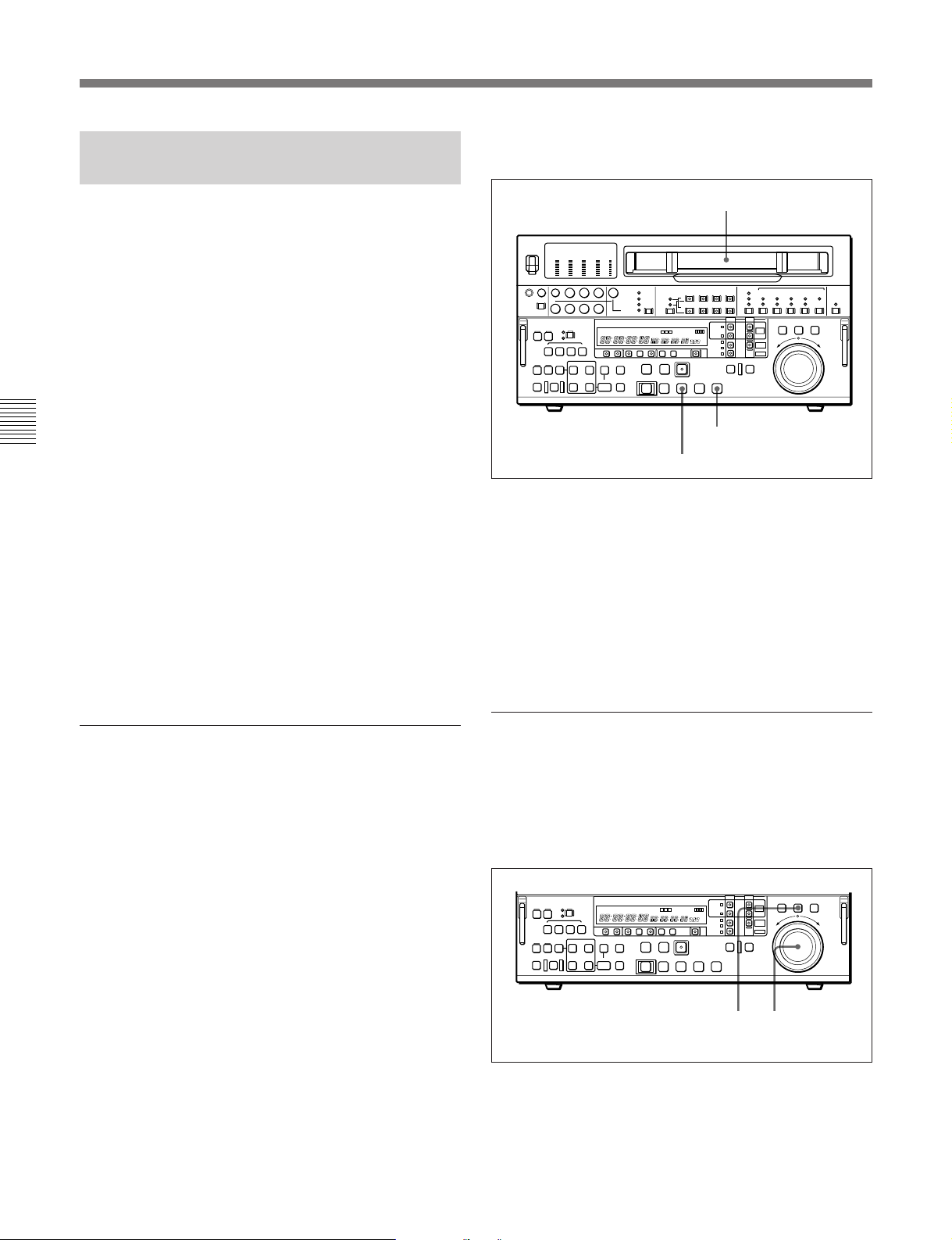
4-2 Playback
4-2-2 Playback/Feed Play
Procedures
This section describes the following types of playback
which the unit can carry out:
•Normal playback
Playback at normal (×1) speed
•Playback in jog mode
Variable speed playback, with the speed determined
by the speed of turning the search dial
•Playback in shuttle mode
Variable speed playback, with the speed determined
by the angular position of the search dial
Chapter 4 Recording and Playback
•Playback in variable mode
Variable speed playback, with the speed finely
determined by the angular position of the search dial
•Playback using the capstan override function (when
using the unit as a VTR)
The playback speed is adjusted temporarily according
to the angular position of the search dial, to align the
playback phase with that of another VTR.
•Playback in feed mode
Playback at any speed selected in the range of 0.1 to
4 times normal speed. High-speed data transfer
through the SDDI DIGITAL OUTPUT connectors is
possible.
To stop playback
Press the STOP button.
Cassette compartment
STOP button
PLAY button
If you play back to the end of the tape
The tape is automatically rewound, and stops.
When using the Dolby noise reduction system
When using an analog Betacam cassette, you can use
Dolby C noise reduction for audio playback.
To activate the Dolby noise reduction system, set the
DOLBY NR switch on the subsidiary control panel to
ON.
Normal playback
When the device on which operations are being carried
out is TAPE, insert a cassette.
For details of how to insert a cassette, see Section 3-5-2,
“Inserting and Ejecting Cassettes” (page 3-10).
To start playback
Press the PLAY button.
Playback starts, the servo locks, and the SERVO
indicator lights.
Playback in jog mode
In jog mode, you can control the speed of playback by
the speed of turning the search dial. The playback
speed range is ±1 times normal speed.
To carry out playback in jog mode, use the following
procedure.
1 1,2,3
1 Press the JOG button or search dial so that the JOG
button is lit.
Pressing the search dial toggles between jog mode
and shuttle mode.
4-8 Chapter 4 Recording and Playback
Page 55
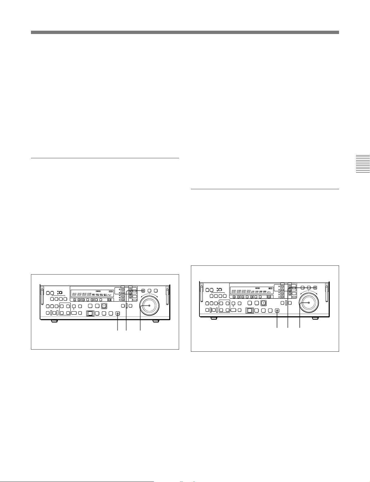
2 Turn the search dial in the desired direction, at the
speed corresponding to the desired playback speed.
Playback in jog mode starts.
The search dial function to toggle between jog
mode and shuttle mode every time being pressed
can be prohibited by changing the setting of
extended menu item 101.
3 To stop playback in jog mode, stop turning the
search dial.
The search dial function to toggle between jog
mode and shuttle mode every time being pressed
can be prohibited by changing the setting of
extended menu item 101.
Playback in shuttle mode
In shuttle mode, you can control the speed of playback
by the angular position of the search dial. The range of
playback speed is as follows:
•Using a Betacam SX tape: ±50 times
•Using an analog Betacam tape: ±35 times (DNWA100/A50/A45) ±42 times (DNW-A100P/A50P/
A45P)
•Using the hard disk: ±100 times
There are detents on the search dial at the still position
and at ±10 times normal speed.
To carry out playback in shuttle mode, use the
following procedure.
To return to normal-speed playback
Press the PLAY button.
To alternate between normal-speed playback
and shuttle mode playback
Set the search dial to the position corresponding to the
desired shuttle playback speed, then switch between
normal-speed playback and shuttle playback by
pressing the PLAY and SHUTTLE buttons alternately.
For intermittent shuttle mode playback, press the
STOP and SHUTTLE buttons alternately.
Playback in variable mode
In variable mode, you can finely control (47 steps) the
speed of playback in the range of ±1 times normal
speed.
There are detents on the search dial at the still position
and at ±1 times normal speed.
To carry out playback in variable mode, use the
following procedure.
Chapter 4 Recording and Playback
13 1,2,3
1 Press the SHUTTLE button or search dial so that
the SHUTTLE button is lit.
Pressing the search dial toggles between jog mode
and shuttle mode.
2 Turn the search dial to the desired angle
corresponding to the desired playback speed.
Playback in shuttle mode starts.
3 To stop playback in shuttle mode, return the search
dial to the center position, or press the STOP
button.
1 2,33
1 Press the VAR button, turning it on.
2 Turn the search dial to the desired angle
corresponding to the desired playback speed.
Playback in variable mode starts.
3 To stop playback in variable mode, return the
search dial to the center position, or press the
STOP button.
Chapter 4 Recording and Playback 4-9
Page 56
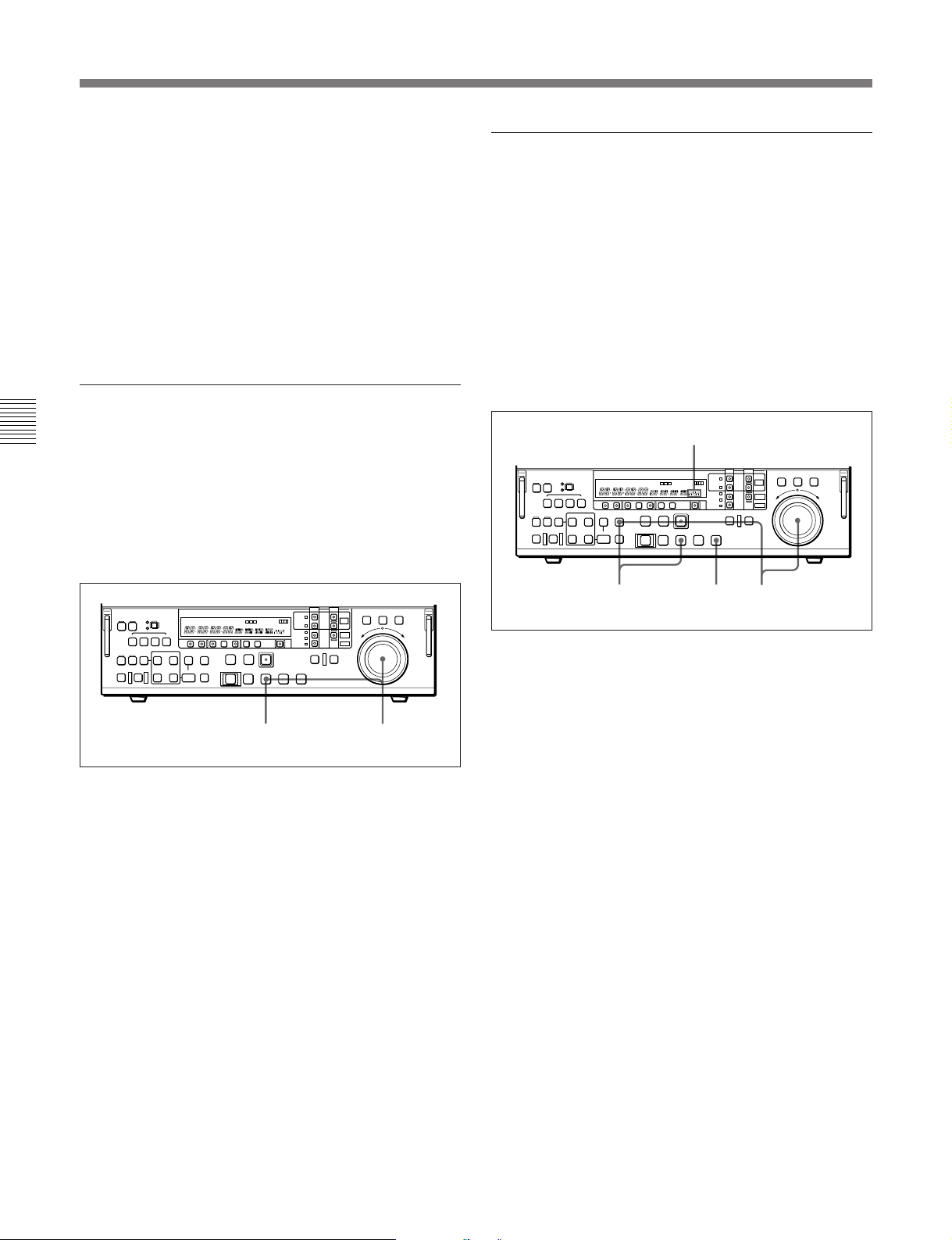
4-2 Playback
To return to normal-speed playback
Press the PLAY button.
To alternate between normal-speed playback
and variable mode playback
Set the search dial to the position corresponding to the
desired variable playback speed, then switch between
normal-speed playback and variable playback by
pressing the PLAY and VAR buttons alternately.
For intermittent variable mode playback, press the
STOP and VAR buttons alternately.
Playback using the capstan override
function
Chapter 4 Recording and Playback
When using the unit as a VTR, you can use the capstan
override function to adjust the playback speed
temporarily. The range of speed adjustment is ±15%
in steps of 1%. This function is convenient for
playback phase synchronization with another VTR
playing back the same program.
Carrying out playback in feed mode
When the recorder is TAPE (using a Betacam SX tape)
or MASTER, and the player is EXT, you can use feed
mode to play back at any speed from 0.1 to 4 times
normal. You can select the playback speed in steps of
0.1 times normal speed. The playback output is output
from the SDDI DIGITAL OUTPUT connectors. This
therefore allows high-speed dubbing to another device
equipped with an SDDI input connector.
Use the following procedure to carry out feed mode
playback.
Event display area
21
1 Hold down the PLAY button, and turn the search
dial in the desired direction to adjust the playback
speed.
The SERVO indicator goes off.
2 When the adjustment is completed, release the
PLAY button.
The tape transport returns to normal speed, and the
SERVO indicator comes on again.
231
1 Hold down the FEED button, and turn the search
dial to set the playback speed.
While you hold down the FEED button, the
playback speed setting for feed mode (initially the
maximum setting) appears in the event display area
as a percentage of normal speed. (For example,
four times normal speed is shown as “400”.)
2 Hold down the FEED button, and press the PLAY
button.
Both buttons light, and playback in feed mode
starts.
3 Where you wish to stop playback, press the STOP
button.
Playback stops.
4-10 Chapter 4 Recording and Playback
Page 57

Feed mode playback when the device on
which operations are being carried out is
PROGRAM
In general, playback is limited to normal speed, but
when in the disk file management menu simple edit
mode and GOP SW editing are selected, feed mode
playback is possible up to a maximum of twice normal
speed.
Notes
•In simple edit mode, insert editing is not possible for
the video and audio channels individually.
•For GOP SW editing, the editing accuracy is 1 frame.
For details of disk file management menu operations, see
Section 7-4, “Disk File Management Menu” (page 7-25).
Chapter 4 Recording and Playback
Chapter 4 Recording and Playback 4-11
Page 58

Page 59
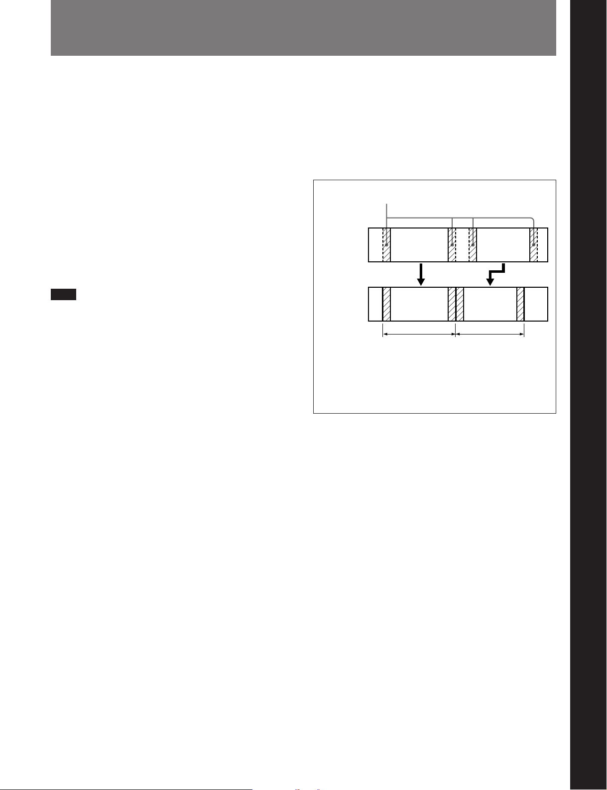
5-1 Overview
Chapter 5 Editing Using the Built-in Hard Disk
For editing using the built-in hard disk, you can carry
out editing between the built-in VTR or an external
VTR and the hard disk, or editing on the hard disk
alone.
In either case, editing is carried out with PROGRAM
specified as the recorder device.
In this system, “PROGRAM” refers to editing data
which determines the sequence in which video and
audio data recorded on the hard disk is to be played
back. On the hard disk, the video and audio data itself
is managed in a notional device called “MASTER”. If
MASTER is specified as the recorder device, it is
possible to record video and audio data, but not to
carry out editing.
Note
After carrying out operations on this unit using the
hard disk, before powering the unit off be sure to press
the EJECT button to close the files on the hard disk.
Powering off the unit with files left open may result in
a loss of system data from the hard disk.
Background information
A section of source material selected by an editing
operation carried out with PROGRAM specified as the
recorder is stored on MASTER as what is termed an
“event”. A margin before and after the edit IN and
OUT points is added to the event, and the resulting
data is then managed on MASTER as a file.
Margin
Data on
player tape
File on hard
disk (DISK
MASTER)
Margin length
Before Version 2.00: Fixed at approximately 3 seconds.
Version 2.00 or later: Varies according to the preroll time
setting of basic menu item 001. Approximately 3 seconds
when the preroll time is 5 seconds (factory default).
Event 1 Event 2
File 1
Event 2Event 1
File 2
Chapter 5 Editing Using the Built-in Hard Disk
The margin is used when modifying edit points, for
example, but in general it is not necessary to be aware
of the margin during editing operations.
Chapter 5 Editing Using the Built-in Hard Disk 5-1
Page 60
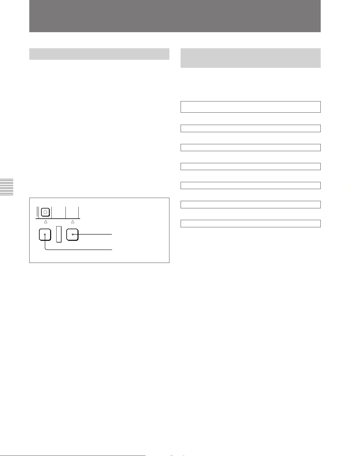
5-2 Basic Editing Operations
5-2 Basic Editing Operations
5-2-1 Control Modes
You can use the following control modes for carrying
out editing with this unit.
•PLAYER mode
The state in which the PLAYER button has been
pressed and turned on (and the RECORDER button is
off). You can control the player from the control
panel of this unit.
•RECORDER mode
The state in which the RECORDER button has been
pressed and turned on (and the PLAYER button is
off). You can control the recorder from the control
panel of this unit.
•SELF mode
The state in which both the PLAYER button and
RECORDER button are off. In this state, you can
control the device specified as the recorder.
Chapter 5 Editing Using the Built-in Hard Disk
EXT
PLAYER RECORDER
RECORDER button
5-2-2 Sequence of Editing
Operations
The following flowchart outlines the sequence of basic
editing operations.
Specifying the devices on which operations are being carried out
(page 5-4)
.
Selecting the editing mode (page 5-4)
.
Setting the recorder and player edit points (page 5-7)
.
Previewing the edit segments (page 5-10)
.
Modifying edit points as necessary (page 5-15)
.
Carrying out the edit (page 5-15)
.
Checking the editing results as necessary (page 5-16)
PLAYER button
5-2 Chapter 5 Editing Using the Built-in Hard Disk
Page 61
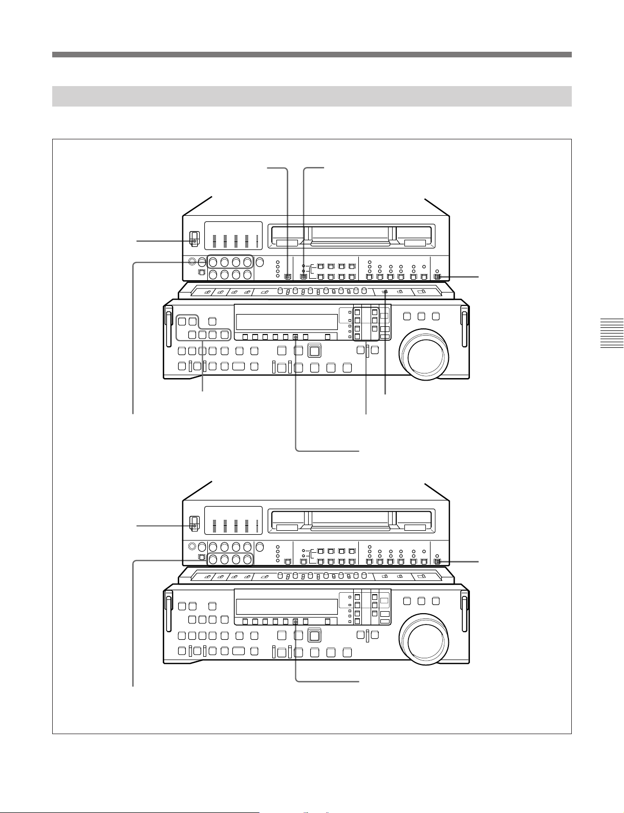
5-2-3 Switch Settings
Before beginning editing, set the switches as follows.
VIDEO INPUT SELECT switch (see page 2-3): select
the input video signal
POWER switch: ON
Editing mode setting section
(page 2-8): selecting the
REC controls (see page 2-3):
adjust the audio recording
levels (see page 4-2)
editing mode (page 5-4)
Audio selection function selector switch (see page 2-3):
select the input audio signals
Recorder (MASTER,
PROGRAM)
REMOTE/LOCAL
switch (see page 2-7):
9P indicator off
Chapter 5 Editing Using the Built-in Hard Disk
REC INHIBIT switch (see page 2-21): OFF
Device specification buttons (see page 2-12): select the device
on which operations are to be carried out (see page 5-4)
CTL/TC/UB button (see page 2-9): TC or CTL
POWER switch: ON
PB controls (see page 2-5): adjust the
audio playback levels
Player (when EXT =
DNW-A100/A100P)
REMOTE/LOCAL
switch (see page 2-7):
9P indicator lit
CTL/TC/UB button (see page 2-9): TC or CTL
Chapter 5 Editing Using the Built-in Hard Disk 5-3
Page 62
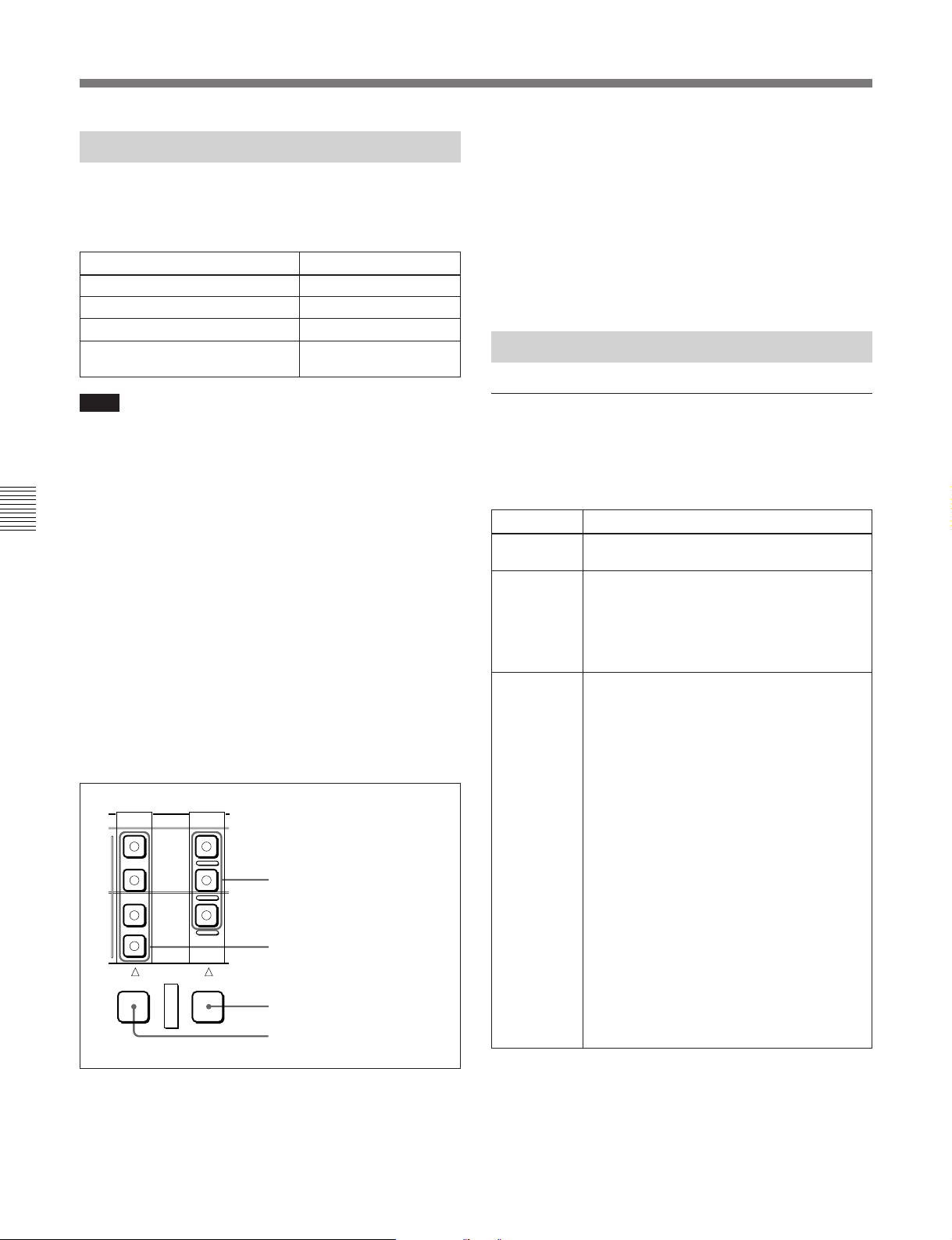
5-2 Basic Editing Operations
5-2-4 Specifying Devices
Devices which can be specified
You can specify any of the following four devices as
recorder or player.
Device to be specified Button to be pressed
Built-in VTR TAPE
Built-in hard disk (for recording)
Built-in hard disk (for editing) DISK PROGRAM
External VTR connected to the
REMOTE-IN(9P) connector
Note
The following device specifications are not possible:
•Specifying EXT (external VTR) as the recorder
•Specifying PROGRAM as the player and MASTER
as the recorder
Chapter 5 Editing Using the Built-in Hard Disk
For details of the operations involved in editing with an
external VTR as the player and the built-in VTR as the
recorder, see Chapter 6, “Editing Without Using the Builtin Hard Disk (Two-VTR Editing).”
To make a device specification
To specify the recorder, hold down the RECORDER
button, and to specify the player, hold down the
PLAYER button, then press the TAPE button, DISK
MASTER button, DISK PROGRAM button, or EXT
button according to the device you wish to specify.
The corresponding device indicator in the
RECORDER or PLAYER column lights.
DISK
PROGRAM
DISK
MASTER
TAPE
DISK MASTER
EXT
RECORDER device specification
buttons
For details, see the section “Nonlinear editing and the
setting of the EDITING MODE button” (page 5-6).
If there is a contradiction in the device
specifications
If for example you specify TAPE for both PLAYER
and RECORDER, the device indicators flash. In this
case, make the required correct device setting.
5-2-5 Selecting the Editing Mode
Editing modes which can be selected
The editing modes which can be selected depend on
the device specified as the recorder, as shown in the
following table.
Recorder Selectable editing modes
TAPE Assemble editing / all-channel insert editing
(ASSEMBLE/ALL)
MASTER Assemble editing / all-channel insert editing
(ASSEMBLE/ALL)
When MASTER is the recorder, only
appended recording of video and audio
material is possible. It is not possible to
specify recorder IN and OUT points.
PROGRAM • In simple edit mode (when the SIMPLE
EDIT indicator is lit):
Assemble editing / all-channel insert editing
(ASSEMBLE/ALL)
• In full edit mode (when the FULL EDIT
indicator is lit):
Insert editing for separate channels
(VIDEO, and AUDIO CH-1 to AUDIO CH-4)
It is possible to carry out separate editing
for each of the video, and audio 1 to audio
4 channels.
The selection of simple edit mode or full edit
mode is made in the disk file management
menu. For details, see page 5-6.
EXT
PLAYER RECORDER
PLAYER device specification
buttons
RECORDER button
PLAYER button
When PROGRAM is specified as the recorder, check
the setting (INS or OVL) of the EDITING MODE
button.
5-4 Chapter 5 Editing Using the Built-in Hard Disk
When PROGRAM is specified as the
recorder, carry out the EDITING MODE
button setting (INS or OVL).
For details, see the section, “Nonlinear
editing and the setting of the EDITING
MODE button” (page 5-6).
For details of the concepts of assemble editing and insert
editing, see the section “Assemble editing and insert
editing” (page 5-5).
Page 63
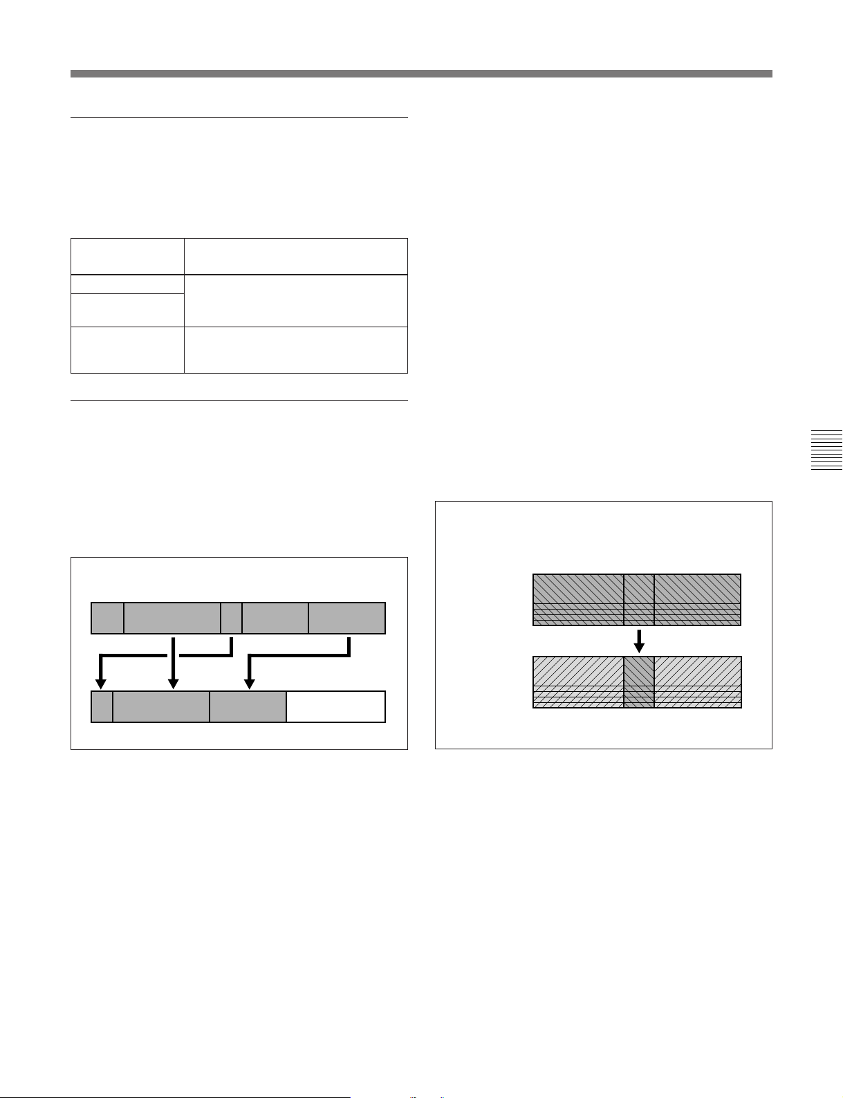
To select the editing mode
To select the editing mode, first press any button in the
assemble assemble/insert editing mode selection
section which is lit, turning it off, then carry out one of
the following operations.
Editing mode to
be selected
Assemble editing Press the ASSEMBLE/ALL button,
All-channel insert
editing
Separate channel
insert editing
Operation
turning it on.
Press any of the VIDEO, and AUDIO
CH-1 to AUDIO CH-4 buttons for the
corresponding channel, turning it on.
Assemble editing and insert editing
Assemble editing (with TAPE as the recorder)
The material from the player is recorded, appended
after the existing recorded material on the recorder.
The video and audio information, and the time code
and CTL signal (if TAPE is the recorder) are all newly
recorded together.
Insert editing (with PROGRAM as the
recorder)
The material from the player is inserted into existing
recorded material on the recorder. This can be done
with no loss of picture continuity (picture breakup) at
the joins.
•With all-channel insert editing (ASSEMBLE/ALL),
the video and all audio channels are recorded
together.
In this mode, it is also possible to specify the end of
the recorded video as the recorder IN point for the
next event to be recorded so that the next event can
be added directly to the existing video.
When you specify an editing section (event) on the
source tape and carry out editing with PROGRAM
specified as the recorder, the event is recorded on the
hard disk (MASTER). At this time, a margin before
and after the IN and OUT points of the event is added
automatically. The resulting data comprising the
event and the margins is then managed on MASTER
as a file.
Concept of all-channel insert editing
(When EDITING MODE button is set to OVL)
Chapter 5 Editing Using the Built-in Hard Disk
Concept of assemble editing
Video and audio material on player
Video and audio material on recorder
If you record video information at an intermediate
point in an existing recording, at the end of the inserted
recording the picture continuity will be lost.
The CTL signal must be recorded on the tape for at
least the preroll time before the recorder IN point.
If time code is already recorded before the editing start
point, time code will be recorded continuously from
the existing time code.
Video and audio material on player
Video
Audio channels
1 - 4
Video
Audio channels
1 - 4
Video and audio material on recorder
Chapter 5 Editing Using the Built-in Hard Disk 5-5
Page 64
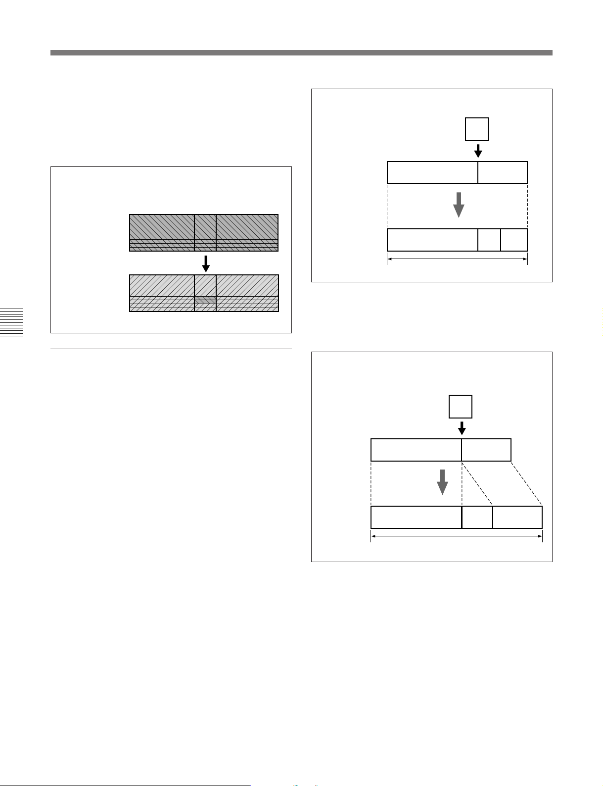
5-2 Basic Editing Operations
•With separate channel insert editing, you can specify
independent IN and OUT points for each of the video
channel and audio channels 1 to 4.
The setting of the EDITING MODE button is
ignored, and the insert editing is always carried out in
OVL mode.
If item C from the player is inserted with the boundary between
A and B specified as the IN point
C
Concept of all-channel insert editing
(When inserting only channels 1 and 2 audio)
Video and audio material on player
Video
Audio channels
1 - 4
Video
Audio channels
1 - 4
Video and audio material on recorder
Chapter 5 Editing Using the Built-in Hard Disk
Nonlinear editing and the setting of the
EDITING MODE button
Nonlinear editing is carried out when PROGRAM is
specified as the recorder. In this case there is no
physical rearrangement of the video and audio
material. Rather, a list is made of the data to be
recalled from the hard disk, since data can be recalled
from the hard disk with instant access in any order.
For the purposes of editing operations, however, it is
not necessary to be aware of this difference in the way
the created program is stored.
For nonlinear insert editing, the effect of editing
operations depends on the setting of the EDITING
MODE button as follows. Make the appropriate
setting for the type of editing you wish to carry out.
Before editing
After editing
AB
AB
The duration does not change.
C
When the EDITING MODE button is set to INS
(insert)
Material after the edit point on the recorder is shifted
by insert editing.
If item C from the player is inserted with the boundary between
A and B specified as the IN point
C
Before
editing
After editing
The duration is increased by the length of C.
AB
ACB
When the EDITING MODE button is set to OVL
(overlay)
Material in the editing section on the recorder is
overwritten by insert editing.
5-6 Chapter 5 Editing Using the Built-in Hard Disk
Necessary conditions for selecting the INS
mode
It is only possible to select the INS mode with the
EDITING MODE button when all the following
conditions hold:
•PROGRAM is selected as the recorder.
•ASSEMBLE/ALL is selected as the editing mode.
•The recorder IN point has been set and the OUT point
has not been set.
•The unit is not in SELF mode (in SELF mode, the
PLAYER and RECORDER buttons are not lit).
If these conditions do not all hold, the setting of the
EDITING MODE button is ignored, and nonlinear
editing is always carried out in OVL mode.
Page 65
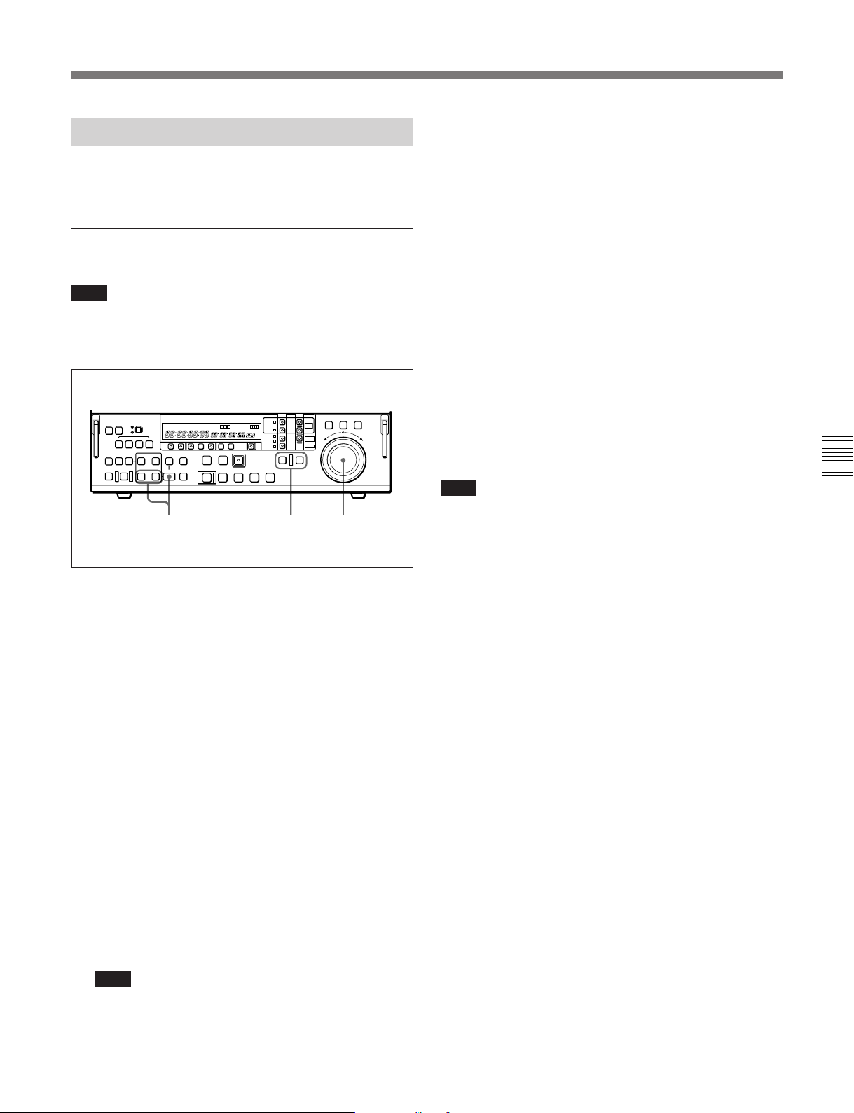
5-2-6 Setting Edit Points
4 Repeat steps 1 to 3 until all the necessary edit
points are set.
Set the edit points for editing between the recorder and
player.
To set an edit point
Note
When MASTER is specified as the player, it is not
possible to specify a pair of IN and OUT points over
different files.
132
When the IN points on both the recorder and
player are set, the PREVIEW/REVIEW button and
AUTO EDIT button flash, and it becomes possible
to carry out a preview or editing operation.
However, when editing an event for the first time
for the purpose of creating a program, it is not
necessary to specify the recorder IN point.
Automatic setting of edit points
Editing requires four edit points: the IN and OUT
points on both the recorder and player. However, once
any three of these points are defined, the last point is
set automatically. For example, if you set the recorder
IN and OUT points, and the player IN point, the player
OUT point is set automatically.
Note
In the following cases, the DELETE button or either
the IN button or the OUT button begins to flash and
you cannot carry out editing:
Chapter 5 Editing Using the Built-in Hard Disk
1 Press the RECORDER button or PLAYER button
to select the device on which you will set the edit
point.
The button which you have pressed lights.
2 Turn the search dial in jog or shuttle mode, and cue
up to the required edit point.
For details of playback in jog or shuttle mode, see the
sections “Playback in jog mode” (page 4-8) and
“Playback in shuttle mode” (page 4-9).
3 At the point at which you wish to set the IN point
or OUT point, hold down the ENTRY button and
press the IN button or OUT button as the case may
be.
When the IN point or OUT point is set, the IN
button or OUT button respectively lights.
Note
When the hard disk (MASTER or PROGRAM) is
specified as the player or recorder, be sure to set
the IN and OUT points so that the duration
between them is at least 16 frames.
When the DELETE button flashes
•The OUT point is before the IN point.
•All four of the recorder IN and OUT points and the
player IN and OUT points have been set.
•MASTER is selected as the player and the player IN
and OUT points are in different files.
•The following conditions regarding event durations
are not met.
(Before Version 2.00): Every event has at least 16
frames.
(Version 2.00 or later): Every event has at least 4
frames and any two adjacent events have a total of
32 frames or more.
Use the DELETE button to delete a redundant edit
point, or set the edit points correctly.
For details of deleting edit points, see Section 5-2-7,
“Modifying and Deleting Edit Points” (page 5-8).
Chapter 5 Editing Using the Built-in Hard Disk 5-7
Page 66

5-2 Basic Editing Operations
To display the time value for an edit point
You can display the time value for an edit point in the
device specification and display section (see page
2-10). The IN point appears in time data display area
1, and the OUT point in time data display area 2.
Time data display area 1
Time data display area 2
21
1 Press the RECORDER button or PLAYER button
Chapter 5 Editing Using the Built-in Hard Disk
to select the device on which you wish to check the
edit point.
1 Press the RECORDER button or PLAYER button
to select the device on which you wish to check the
duration.
The button you have pressed lights.
2 Hold down both the IN button and OUT button.
While you hold down the buttons, the duration is
displayed across time data display areas 1 and 2.
5-2-7 Modifying and Deleting
Edit Points
If the edit points are not set correctly, for example if an
OUT point is before a corresponding IN point, the
DELETE button flashes, and it is not possible to carry
out a preview or editing operation. In this case, either
modify the erroneous edit point, or first delete it and
then enter it correctly.
The button you have pressed lights.
2 Hold down the IN button or OUT button according
to the edit point you wish to check.
While you hold down the button, the IN indicator
or OUT indicator of time data display area 1 or 2
lights, and the time value of the edit point is
displayed.
To display the duration between two edit
points
You can display the duration between two edit points
in the following three cases, in the device specification
and display section (see page 2-10).
•When both the IN point and OUT point are set: the
duration of the segment between the two points
•When one only of the IN point and OUT point is set:
the duration of the segment between the point which
is set and the current position
•When neither of the IN point and OUT point is set:
the duration of the previous editing segment
The duration is displayed across time data display
areas 1 and 2, thus: “DURATION 00:01:10:00”.
To display a duration, use the following procedure.
Modifying an edit point
To modify an edit point, use the following procedure.
21
1 Press the RECORDER button or PLAYER button
to select the device on which you wish to modify
the edit point.
The button you have pressed lights.
5-8 Chapter 5 Editing Using the Built-in Hard Disk
Page 67
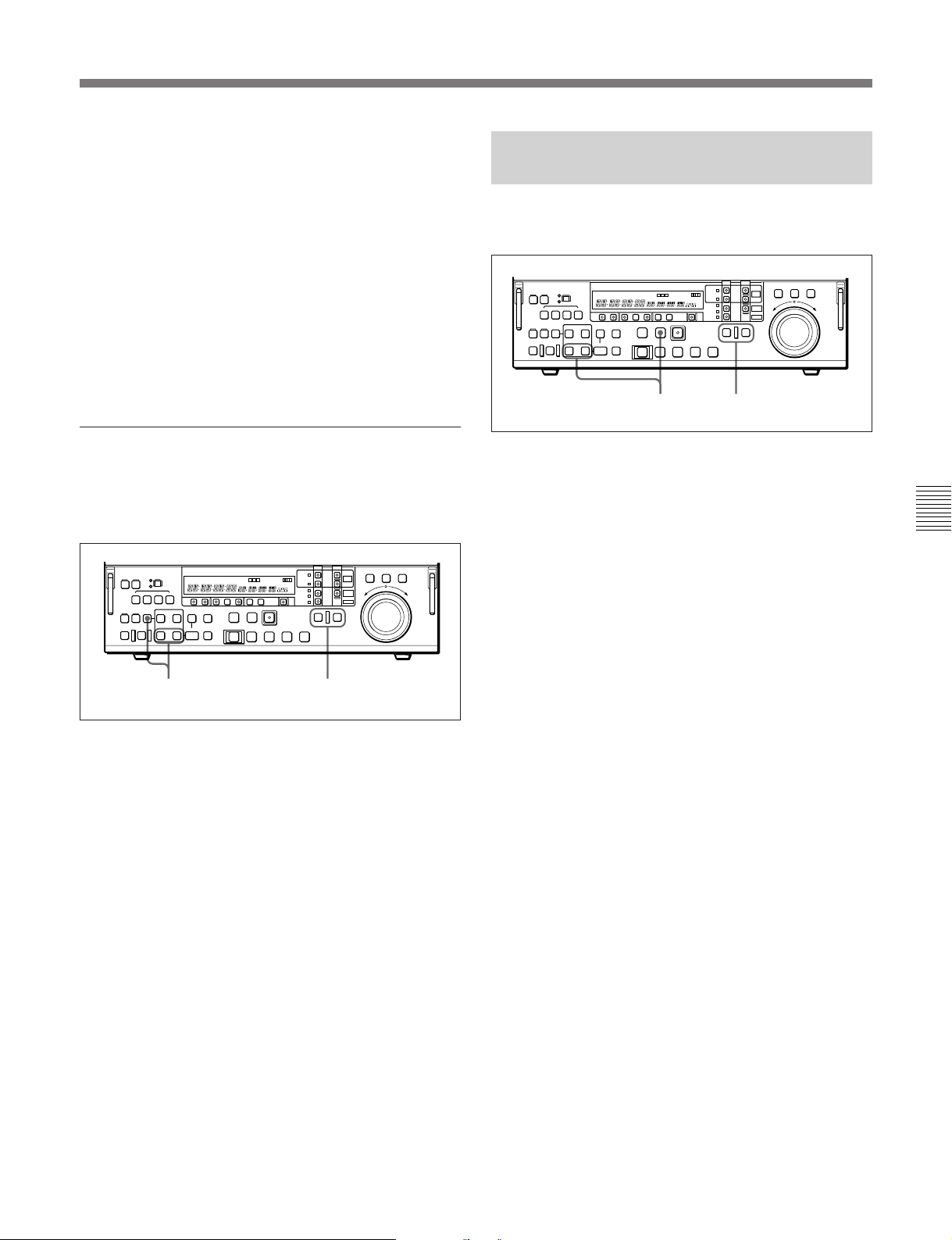
2 Hold down the IN button or OUT button according
to the edit point you wish to modify, and turn the
search dial as follows:
•To advance the edit point: the forward direction
•To delay the edit point: the reverse direction
The time value for the IN or OUT point displayed
in time data display area 1 or 2 increases or
decreases according to the direction in which you
turn the search dial.
3 When the modification is completed, release the
button you pressed in step 2.
Deleting an edit point
To delete an edit point, use the following procedure.
You can use the same procedure whether or not the
DELETE button is flashing.
5-2-8 Cue-up to Edit Points and
Preroll
To preroll to an edit IN point or cue up to any edit
point, use the following procedure.
12
1 Press the RECORDER button or PLAYER button
to select the device on which you wish to operate.
The button you have pressed lights.
Chapter 5 Editing Using the Built-in Hard Disk
2 • To cue up to an edit point
Hold down the IN button or OUT button
according to the edit point to which you wish to
cue up, and press the PREROLL button.
2 1
1 Press the RECORDER button or PLAYER button
to select the device on which you wish to delete the
edit point.
The button you have pressed lights.
2 Hold down the DELETE button and press the lit
IN button or OUT button according to the edit
point you wish to delete.
The IN point or OUT point is deleted according to
which button you pressed, and the DELETE button
goes off.
To restore a deleted edit point
To restore an edit point immediately after deleting it,
hold down the IN button or OUT button according to
the edit point you wish to restore, and press the
RECALL button.
This cues up to the edit point you have selected.
•To preroll
Press the PREROLL button.
This cues up to a position 5 seconds before the
edit IN point, and stops.
To change the preroll time
The factory default setting for the preroll time is 5
seconds, but basic menu item 001 allows you to
change this to any value from 0 to 30 seconds. If you
change the preroll time, make sure that the setting is
not longer than the recording length before the edit IN
point.
Note that for automatic editing, the preroll time setting
on the recorder takes precedence.
For details of the basic menu, see Section 7-2, “Basic
Menu” (page 7-1).
Chapter 5 Editing Using the Built-in Hard Disk 5-9
Page 68

5-2 Basic Editing Operations
5-2-9 Preview
When you have set the edit points, the PREVIEW/
REVIEW button flashes, indicating that you can carry
out a preview.
To carry out a preview, use the following procedure.
1 Press the RECORDER button, turning it on.
2 Press the PREVIEW/REVIEW button.
Chapter 5 Editing Using the Built-in Hard Disk
The PREVIEW/REVIEW button changes from
flashing to continuously lit, and the preview is
carried out.
At the end of the preview, the PREVIEW/
REVIEW button goes off.
To stop the preview
Press the STOP button.
To return to the IN point or OUT point
Press the PREROLL button and the IN button or OUT
button simultaneously.
To return to the preroll point
Press the PREROLL button.
After the preview, make adjustments to the edit points,
then repeat the preview as necessary.
Monitor output
During previews and editing, the monitor output video
depends on the settings shown in the following table.
Monitor output video during previews and editing
Device
specification
Player Recorder
a)
EXT
12
TAPE TAPE Editing not possible
PROGRAM
MASTER TAPE
TAPE
MASTER B-P-B B-P-B Editing
PROGRAM R-P-P B-P-B P-P-P P-P-P
MASTER B-P-B P-P-PB-P-B –
PROGRAM R-B-B B-P-B – P-P-P
TAPE
MASTER Editing not possible
PROGRAM R-P-R - -P-B
MASTER Editing not possible
PROGRAM R-P-R - -P-B –
During previews
RECORDER
mode
b)
R-P-P
b)
R-B-B B-P-B – P-P-P
b)
R-B-B B-P-B – P-P-P
PLAYER
mode
B-P-B
SELF
mode
R-P-P R-P-P
not
possible
–
a) Only when the external input is other than SDDI.
b) Assemble mode editing only.
c) When an OUT point is set, program information is saved
to the hard disk but there is no output to the monitor.
If you execute an edit before setting the OUT point and
set the OUT point during the edit, the editing mode
becomes R-P- - (no postroll).
d) Monitor output switching from R to P will not exactly
represent the results of editing.
e) When audio editing only is performed in SELF mode,
monitor output will be R-P-R.
f) When audio editing only is performed on Version 2.00
or later units, monitor output will be R-P-R.
During
editing
d)
P-P-P
e)
f)
c)
c)
For details of how to modify or delete edit points, see
Section 5-2-7, “Modifying and Deleting Edit Points” (page
5-8).
5-10 Chapter 5 Editing Using the Built-in Hard Disk
Page 69
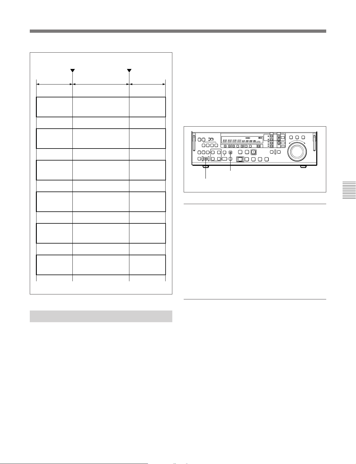
Preroll
R-P-R
Recorder
playback
B-P-B
Edit segment
Player playback
To carry out automatic editing in feed mode, hold
down the FEED button and press the AUTO EDIT
OUT pointIN point
button.
This increase the data transfer rate to the maximum
Postroll
Recorder
playback
possible, and carries out the automatic edit.
For details of the procedure for feed mode settings, see the
section “Playback in jog mode” (page 4-8).
On how to make settings for full edit mode and simple edit
mode, see Section 7-4, “Disk File Management Menu”
(page 7-25).
Black image
(mute)
R-B-B
Recorder
playback
R-P-P
Recorder
Playback
P-P-P
Player playback Player playback Player playback
- - P-B
No preroll is
made.
Player playback
Black image (mute)
Player playback Player playback
Player playback
Black image
(mute)
Black image
(mute)
Black image
(mute)
FEED button
AUTO EDIT button
Chapter 5 Editing Using the Built-in Hard Disk
Monitor output
The monitor output video during editing and previews
depends on device specification and other settings.
For details, see the table “Monitor output video during
previews and editing” on the previous page.
Monitoring during automatic editing in feed
mode
The monitor output is P-P-P.
Stopping the editing operation
5-2-10 Carrying Out Editing
When you have set the edit points, press the AUTO
EDIT button when it is flashing.
The AUTO EDIT button changes from flashing to
continuously lit, and the editing operation begins.
At the end of the editing operation, the AUTO EDIT
button goes off.
Carrying out high-speed editing in feed mode
When the built-in VTR is specified as the player (using
Betacam SX tape) and the built-in hard disk
(MASTER or PROGRAM) is specified as the
recorder, you can carry out high-speed automatic
editing in feed mode (maximum speed: 3 times
normal speed in full edit mode or 4 times normal speed
in simple edit mode).
You can use either of the following methods to stop an
editing operation in progress:
•Hold down the OUT button and press the ENTRY
button.
The point where you press the two buttons becomes
the OUT point, and editing stops.
•Press the STOP button.
This aborts the editing, and the AUTO EDIT button
and PREVIEW/REVIEW button flash. The IN and
OUT point settings are unchanged, and you can carry
out a preview or re-execute the automatic editing.
Chapter 5 Editing Using the Built-in Hard Disk 5-11
Page 70
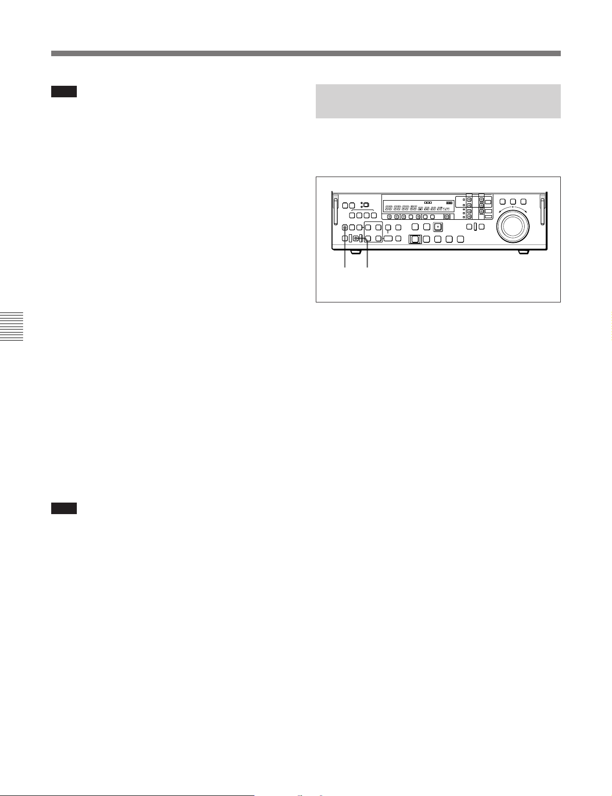
5-2 Basic Editing Operations
Note
When MASTER or PROGRAM is specified as the
player and PROGRAM is specified as the recorder,
executing the automatic editing with the recorder OUT
point set causes the program information to be saved to
the hard disk and no image to be output to the monitor.
As a result, it is not possible to abort the editing
operation. It is, however, possible to undo the effect of
the editing operation after it has completed. (See the
next section 5-2-11, “Undoing an Editing
Operation.”)
Reviewing the editing results
After carrying out an editing operation, you can carry
out a review, to check the editing results on the
monitor.
To carry out a review, press the PREVIEW/REVIEW
button after carrying out the edit and before you set
any new edit points or make other settings.
Chapter 5 Editing Using the Built-in Hard Disk
The PREVIEW/REVIEW button lights, and the review
is carried out.
At the end of the review the PREVIEW/REVIEW
button goes off, and the recorder returns to the OUT
point.
5-2-11 Undoing an Editing
Operation
When PROGRAM is specified as the recorder, you can
use the following procedure to undo the effect of the
immediately previous automatic editing operation.
12
1 Immediately after the automatic editing operation
has completed, press the UNDO button, turning it
on.
The AUTO EDIT button flashes.
2 Press the AUTO EDIT button.
To adjust the edit points and reexecute the
edit after automatic editing
Hold down the RECALL button or DELETE button,
and press the ENTRY button to recall the edit points.
After adjusting the edit points, press the AUTO EDIT
button to carry out the edit again.
Note
When PROGRAM is specified as the recorder, and the
EDITING MODE button is set to INS, the event
pertaining to an automatic editing operation is inserted
at the recorder IN point. An event already present at
the recorder IN point is not overwritten, but slides
forward.
For details of how to adjust edit points, see Section 5-2-7,
“Modifying and Deleting Edit Points” (page 5-8).
This undoes the effect of the immediately previous
automatic editing operation, and the UNDO button
goes off.
Aborting the undo operation before carrying
out step 2
Press the UNDO button again, turning it off.
This returns to the state before you carried out step 1.
5-12 Chapter 5 Editing Using the Built-in Hard Disk
Page 71

5-2-12 Standalone Editing
This refers to editing using as the player an external
device which cannot be controlled remotely through
the REMOTE-IN(9P) connector. For example, you
can record a color bar signal from a signal generator in
the joints between the events of an already completed
program.
Carrying out standalone editing
To carry out standalone editing using the built-in hard
disk, specify EXT as the player and PROGRAM as the
recorder.
First use the VIDEO INPUT SELECT switch to select
the signal being generated by the signal generator
connected to the unit, then with both the PLAYER
button and RECORDER button off (the SELF mode),
set the IN point.
The AUTO EDIT button flashes, and it is now possible
to carry out automatic editing.
If necessary, you can also first set the OUT point.
Chapter 5 Editing Using the Built-in Hard Disk
To record an external signal in SELF mode
specifying MASTER as the recorder
Press the REC button and PLAY button
simultaneously.
Chapter 5 Editing Using the Built-in Hard Disk 5-13
Page 72
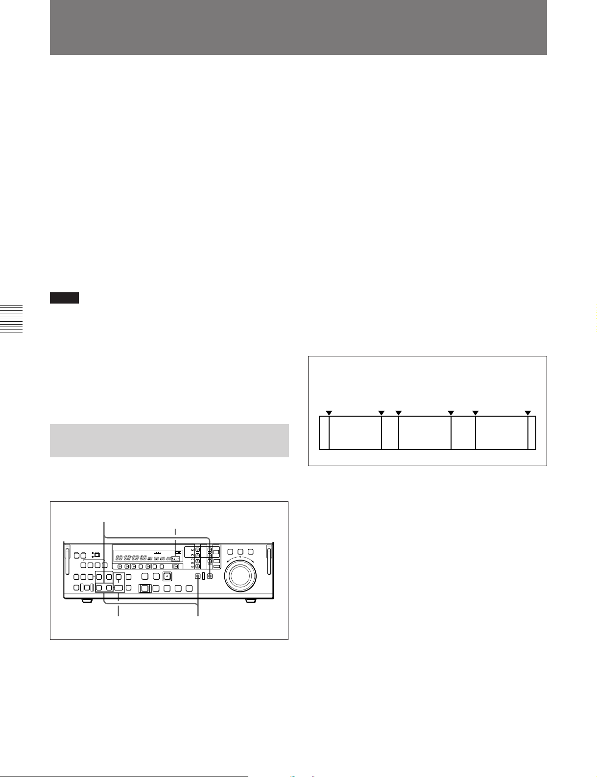
5-3 Multi-Event Editing
5-3 Multi-Event Editing
On the device specified as the player, it is possible to
set up to 100 sets of player IN and OUT points, and
then to edit (playback and record) continuously the
segments defined by these IN and OUT points (the
segments being hereafter referred to as “events”).
When TAPE is specified as the player and PROGRAM
as the recorder, roughly specifying a number of edit IN
and OUT points on the tape and carrying out multievent editing allows you to reduce the editing time and
improve the efficiency with which the hard disk
capacity is used. After carrying out multi-event
editing, you can adjust the edit points of each event.
For details of how to adjust edit points after carrying out
multi-event editing, seeSection 5-4-1, “Modifying Edit
Points After Carrying Out Editing” (page 5-17).
Notes
•It is not possible to carry out multi-event editing with
TAPE specified as the recorder.
Chapter 5 Editing Using the Built-in Hard Disk
•It is possible to specify only an IN point on the
recorder.
•The event specifications are lost when the system is
powered off or when the player specification is
changed.
1 Set both of the player IN and OUT points.
If you specify the player IN point to be after the
OUT point
The DELETE button flashes.
Holding down the DELETE button, press the IN or
OUT button to delete the player IN or OUT point,
then enter the correct value.
2 Holding down the EVENT button, press the
ENTRY button.
The event defined by the player IN and OUT
points set in step 1 is saved; the EVENT button
lights, and the event number is displayed in the
event display area.
(The event numbers start from 1, and continue in
sequence 2, 3, 4, etc.)
Repeat steps 1 and 2 for each of the events
(maximum 100) you wish to save.
Events saved on the player tape
IN point
OUT
point
IN point
OUT
point
IN point
OUT
point
5-3-1 Saving Event
Specifications
To save event specifications use the following
procedure.
3
Event display area
21
Event 1
Event 2
Event n
3 Set either the recorder IN point or OUT point.
(This step is not required when MASTER is the
recorder.)
If both recorder IN and OUT points are set
(Before Version 2.00)
The recorder OUT point is ignored.
(Version 2.00 or later)
The DELETE button flashes.
Holding down the DELETE button, press the OUT
button to delete the recorder OUT point.
5-14 Chapter 5 Editing Using the Built-in Hard Disk
Page 73
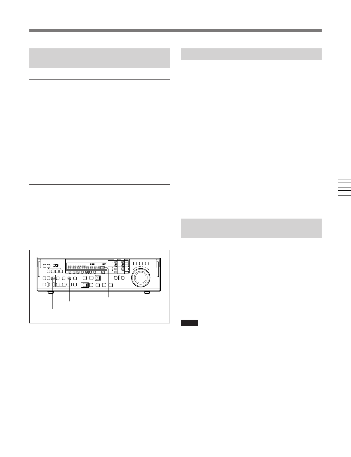
5-3-2 Modifying and Deleting
Events
Modifying the event IN and OUT points
Once an event has been saved, it is not possible to
modify the IN and OUT points. First delete the event,
then save a new version with the required settings.
For details of how to adjust edit points before saving the
event, see Section 5-2-7, “Modifying and Deleting Edit
Points” (page 5-8).
For details of how, after carrying out editing, to recall an
event from the program and modify it, see Section 5-4-1,
“Modifying Edit Points After Carrying Out Editing” (page
5-17).
Deleting an event
When events are saved, you can delete them
sequentially from the newest event.
To delete the newest event, hold down the DELETE
button and press the EVENT button.
This deletes the newest event, and the event number
shown in the event display area is decremented by one.
EVENT button
DELETE button
Event display area
5-3-3 Preview
When it is possible to carry out a preview, the
PREVIEW/REVIEW button flashes.
To carry out the preview, press the PREVIEW/
REVIEW button.
•In the case of an event not yet saved (the IN button
and OUT button are both lit, and the EVENT button
is off)
The current event only is previewed.
•After an event is saved (the IN button and OUT
button are both off, and the EVENT button is lit)
All of the saved events are previewed as a continuous
editing segment.
In either case, only the player playback video for the
editing segment is monitored. (Player preview)
If, however, MASTER or PROGRAM is the player
and PROGRAM is the recorder, then the recorder
playback video for the preroll and postroll segments
can also be monitored (R-P-R preview).
5-3-4 Carrying Out Multi-Event
Editing
When the events have been saved, and you can carry
out multi-event editing, the AUTO EDIT button
flashes.
To carry out the multi-event editing, press the AUTO
EDIT button.
The AUTO EDIT button changes from flashing to
continuously lit, and the editing operation starts.
When the editing operation completes, the AUTO
EDIT button goes off.
Chapter 5 Editing Using the Built-in Hard Disk
By repeating this operation, you can delete any number
of consecutive events.
If all the events are deleted, the EVENT button goes
off.
Notes
•When you carry out the editing, the saved events are
deleted.
•In the multi-event editing process, if there are edit
points set but not saved as an event, they are ignored.
Chapter 5 Editing Using the Built-in Hard Disk 5-15
Page 74

5-3 Multi-Event Editing
Monitoring during editing
During editing, you can monitor the player events in
the same way as in a preview.
Note
When MASTER or PROGRAM is specified as the
player and PROGRAM is specified as the recorder,
executing the multi-event editing causes the program
information to be saved to the hard disk and no image
to be output to the monitor.
Stopping the editing operation (with TAPE or
EXT specified as the player)
To stop a multi-event editing operation in progress,
press the STOP button.
Reviewing the editing results
After carrying out an editing operation, you can carry
out a review, to check the editing results on the
Chapter 5 Editing Using the Built-in Hard Disk
monitor.
To carry out a review, press the PREVIEW/REVIEW
button after carrying out the edit and before you set
any new edit points or make modifications.
The PREVIEW/REVIEW button lights, and the review
is carried out.
At the end of the review the PREVIEW/REVIEW
button goes off, and the recorder returns to the OUT
point of the last event.
5-16 Chapter 5 Editing Using the Built-in Hard Disk
Page 75

5-4 Special Nonlinear Editing Operations
This section describes the following special editing
operations which you can use for nonlinear editing on
the unit:
•Modifying edit points after carrying out editing
•Deleting an arbitrary segment after carrying out
editing
•Reordering events after carrying out editing
5-4-1 Modifying Edit Points After
Carrying Out Editing
You can recall an event from a created program and
modify the edit points.
With PROGRAM specified as the recorder, and with
both the PLAYER button and RECORDER button off
(the SELF mode), carry out the following procedure.
4 Holding down RECALL button, press the EVENT
button, turning it on.
The IN and OUT points of the event you selected
in step 3 are recalled and the IN button and OUT
button come on.
Aborting the modification of the edit points
Press the RECALL button once more, turning it
off.
5 Carry out either of the following operations.
•Hold down the IN button or OUT button (or
AUDIO IN button or AUDIO OUT button)
according to the edit point you wish to modify,
and turn the search dial to adjust the edit point.
•Hold down the ENTRY button, and press the IN
button or OUT button (or AUDIO IN button or
AUDIO OUT button) according to the edit point
you wish to modify, and set a new value.
Chapter 5 Editing Using the Built-in Hard Disk
6 Press the AUTO EDIT button, carrying out edit
point modification.
4253 (3)61
1 Select the editing mode.
•For assemble editing or all-channel insert
editing
Press the ASSEMBLE/ALL button, turning it on.
•For separate channel insert editing
Press one of the VIDEO, and AUDIO CH-1 to
AUDIO CH-4 buttons, turning it on.
When the ASSEMBLE/ALL button is lit, you can
select INS (insert) or OVL (overlay) mode. In
other cases, OVL is selected automatically. The
editing results depend on which of INS and OVL is
selected.
For details, see the section “Nonlinear editing and the
setting of the EDITING MODE button” (page 5-6).
2 Press the PLAY button to start playing back the
program.
Notes
•For an event which has different edit points specified
for different channels, when you have selected
assemble editing or all-channel insert editing (the
ASSEMBLE/ALL button is lit), it is not possible to
modify the edit points.
•Events within a program comprise data recorded as
files on the hard disk MASTER. It is not possible to
modify the edit points outside the range of data
physically present.
Data on hard
disk MASTER
Events
within the
program
Extension of events in this way is not possible.
File
Event
Event
3 At any point in the event of which you wish to
modify an edit point, press the STOP button or
press the search dial to stop the playback.
Chapter 5 Editing Using the Built-in Hard Disk 5-17
Page 76
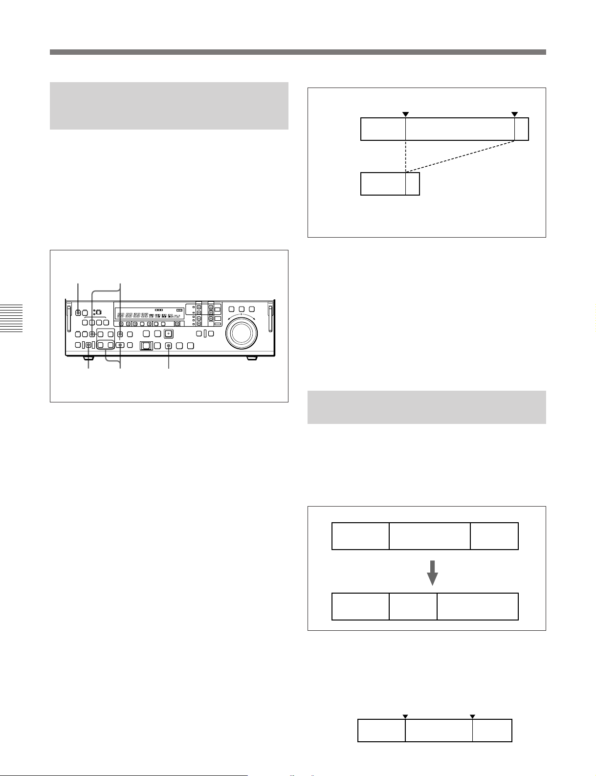
5-4 Special Nonlinear Editing Operations
5-4-2 Deleting an Arbitrary
Segment After Carrying Out
Editing
You can delete an arbitrary segment from a created
program.
With PROGRAM specified as the recorder, and with
both the PLAYER button and RECORDER button off
(the SELF mode), carry out the following procedure.
(This operation is only possible when the editing mode
selection is such that the ASSEMBLE/ALL button is
lit.)
1
Chapter 5 Editing Using the Built-in Hard Disk
4
IN point OUT point
Before
deletion
After
deletion
Frames are deleted from the IN point frame to the frame
before the OUT point frame. The OUT point frame is not
deleted.
To delete the entire segment after the IN point
Carry out the procedure described above without
setting an OUT point.
To delete the entire segment before the OUT
point
Carry out the procedure described above without
setting an IN point. (The OUT point frame is not
deleted.)
Deleted segment
5
32
1 Press the ASSEMBLE/ALL button, turning it on.
2 Press the PLAY button to start playing back the
program.
3 At the required positions, hold down the ENTRY
button and press the IN button or OUT button to
define the segment to be deleted.
4 Hold down the DELETE button, and press the
EVENT button.
The DELETE button and EVENT button light, and
the PREVIEW/REVIEW button and AUTO EDIT
button begin to flash.
Aborting the deletion of the segment
Press the DELETE button once more, turning it
off.
5-4-3 Reordering Events After
Carrying Out Editing
By applying the operations described above, you can
change the order of events within a program.
This section describes the sequence of operations
required to reorder events as shown in the following
figure.
Before reordering the events
Event 1
After reordering the events
Event 1 Event 3 Event 2
Event 2 Event 3
1 Specify PROGRAM as both recorder and player.
5 Press the AUTO EDIT button.
This deletes the segment defined in step 3 from the
program.
5-18 Chapter 5 Editing Using the Built-in Hard Disk
2 Specify the IN and OUT points of event 2 as the
player IN and OUT points.
Player IN point
Event 1 Event 2 Event 3
Player OUT point
Page 77
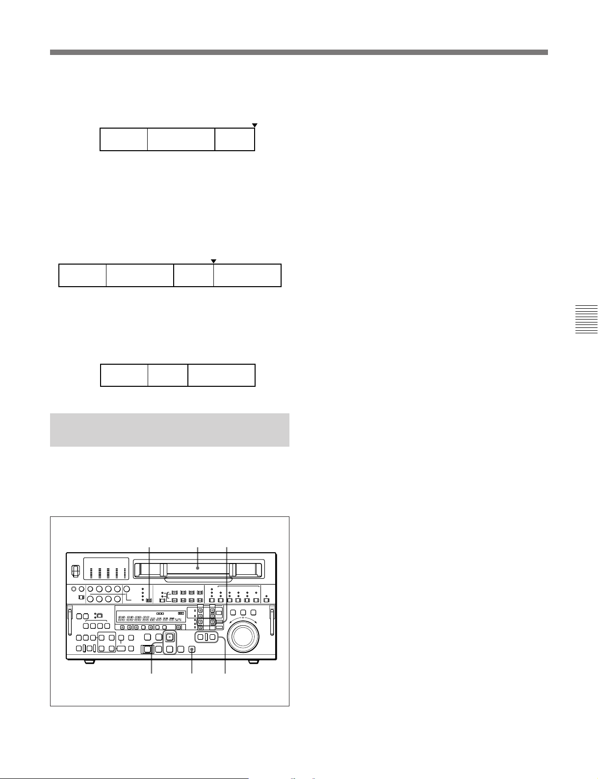
3 Specify the OUT point of event 3 as the recorder
IN point.
Recorder IN point
Event 1 Event 2 Event 3
The AUTO EDIT button and PREVIEW/REVIEW
button light.
1 Make sure the PLAYER button and RECORDER
button are both off. (SELF mode)
If either or both of them are on, press them, turning
them off.
2 Use the VIDEO INPUT SELECT switch to select
the input signal.
3 Insert a cassette.
4 Carry out automatic editing.
This records event 2 at the recorder IN point.
Recorder IN point
Event 2 Event 3 Event 2Event 1
5 Use the procedure described in Section 5-4-2,
“Deleting an Arbitrary Segment After Carrying
Out Editing” to delete original event 2 between
events 1 and 3.
Event 1
5-4-4 Simultaneous Recording
on Tape and the Hard Disk
An external signal input to the unit can be recorded on
tape and on the hard disk simultaneously. To do this,
specify EXT as the player and MASTER as the
recorder, then proceed as follows.
Event 3 Event 2
2 5
3
4 Hold down the PLAY button and press the REC
button.
Recording on the hard disk (DISK MASTER)
starts.
5 Press the TAPE button in the PLAYER row or
RECORDER row.
The TAPE button starts flashing.
While the TAPE button is flashing, the tape/disk
transport control section on the lower control panel
is operable to control the tape transport.
6 Hold down the PLAY button and press the REC
button.
Recording on the tape starts.
7 To stop recording, operate as follows.
• To stop recording on the tape
Press the STOP button.
•To stop recording on the hard disk
Press the PLAYER button or RECORDER
button, turning the flashing TAPE button off, then
press the STOP button.
Chapter 5 Editing Using the Built-in Hard Disk
4,6 7
To eject the cassette
Press the TAPE button, causing it to start flashing,
then press the EJECT button
1,(7)
Chapter 5 Editing Using the Built-in Hard Disk 5-19
Page 78
5-5 Summary of Editing Operations
5-5 Summary of Editing Operations
The following figure summarizes the general flow of
operations in a typical multi-event editing operation
from material originally acquired on tape.
Specify TAPE as the player and PROGRAM as the recorder.
.
Turn the ASSEMBLE/ALL button on.
.
Specify the editing segments on the player. (Save the events.)
.
Set the recorder IN point.
• This step is necessary when adding editing to an existing
.
program. When creating a new program, it is not
necessary.
The AUTO EDIT button and PREVIEW/REVIEW button flash.
.
Carry out automatic editing.
Chapter 5 Editing Using the Built-in Hard Disk
• When using Betacam SX tape, high-speed editing is
possible.
.
For details, see the section “Carrying out high-speed
editing in feed mode” (page 5-11)
The program is created.
(The data for the events is recorded as files on the hard
disk (DISK MASTER).)
Reference for operations:
Section 5-2-4, “Specifying Devices” (page 5-4)
Reference for operations:
Section 5-2-5, “Selecting the Editing Mode” (page 5-4)
References for operations:
Section 5-2-6, “Setting Edit Points” (page 5-7)
Section 5-3-1, “Saving Event Specifications” (page 5-14)
Reference for operations:
Section 5-2-6, “Setting Edit Points” (page 5-7)
References for operations:
Section 5-2-10, “Carrying Out Editing” (page 5-11)
Section 5-3-4, “Carrying Out Multi-Event Editing” (page 5-15)
When modification of edit points or other
operations are necessary after carrying out
editing
See Section 5-4-1, “Modifying Edit Points After Carrying
Out Editing” (page 5-17).
5-20 Chapter 5 Editing Using the Built-in Hard Disk
Page 79
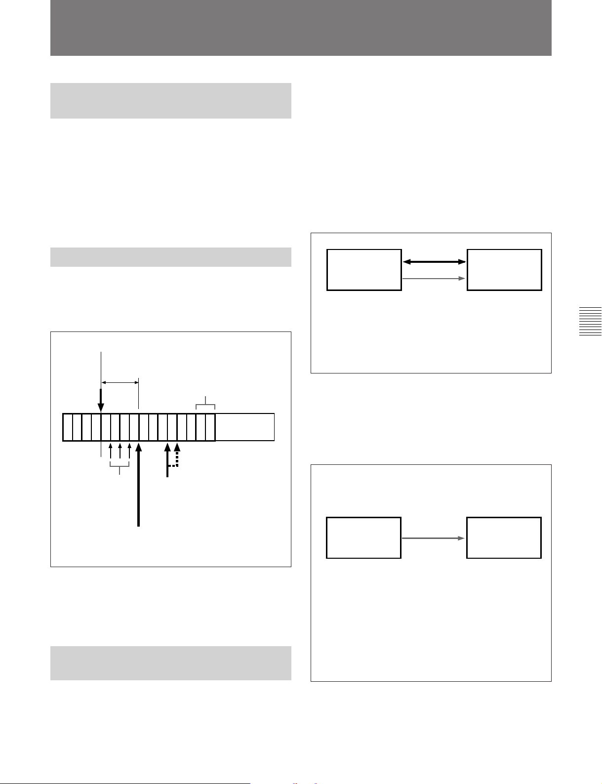
5-6 Points to Remember About Editing
Therefore, when editing to tape from the start of your
5-6-1 Automatic Previews in Tape
Editing
When editing with TAPE selected as the recorder, a
preview is conducted automatically when you press the
AUTO EDIT button and edit execution begins after the
preview.
Tracking information about the IN points on the tape is
required in automatic editing. This information is
collected during the preview.
5-6-2 Tape Editing Precision
program, you should insert about 30 seconds of
throwaway cuts in the preroll segment at the start of
the program.
You can use either of the following two methods to
insert throwaway cuts into a program that has already
been created.
Inserting cuts by insert editing with an
external player
Use insert editing to insert throwaway cuts from an
external player at the start of your program.
External player
9-pin remote
control
This unit (recorder)
Tape editing is carried out as assemble editing in units
of GOPs (Group of Picture = 2 frames). Tape editing
precision is ±1 frame. The smallest editing segment
that can be set is 2 GOPs (4 frames).
Current editing point
Minimum editing
segment (4 frames)
GOP = 2 frames
Tape
Unrecorded
section
No new edit points
can be set here.
If you set an IN point here, the unit
executes the edit after automatically
shifting the IN point by 1 frame.
You can execute an
edit after setting an
IN point here.
There is no fixed relationship between odd-numbered
or even-numbered frames and GOP divisions. The
relationship depends on current conditions.
5-6-3 Preroll In Editing From
Hard Disk to Tape
Output
Play back the tape
containing the
throwaway cuts.
Audio and
video signals
Settings on this unit
Player: EXT
Recorder: PROGRAM
Edit channel: Assemble
(ASSEMBLE/ALL button lit)
Edit mode: Insert (INS indicator lit)
Input
Recording signals from an external signal
generator
Manually record signals from an external signal
generator to this unit’s hard disk (MASTER), then
insert them as throwaway cuts at the start of your
program.
Step 1: Manually record signals from an external signal
generator to this unit’s hard disk (MASTER) as throwaway
cuts.
External signal
generator
Generate the signals
to be used as
throwaway cuts.
Step 2: Set up the unit as described below and use insert
editing to insert the throwaway cut signals recorded to the
hard disk (MASTER) in step 1 at the start of your program.
Settings on this unit
Player: MASTER
Recorder: PROGRAM
Edit channel: Assemble (Assemble/ALL button lit)
Edit mode: Insert (INS indicator lit)
Signals
This unit (recorder)
Audio and video
input
Settings on this unit
Player: EXT
Recorder: MASTER
Chapter 5 Editing Using the Built-in Hard Disk
When you select TAPE as the recorder and MASTER
or PROGRAM as the player, preroll is required for
both the recorder and player.
Chapter 5 Editing Using the Built-in Hard Disk 5-21
Page 80
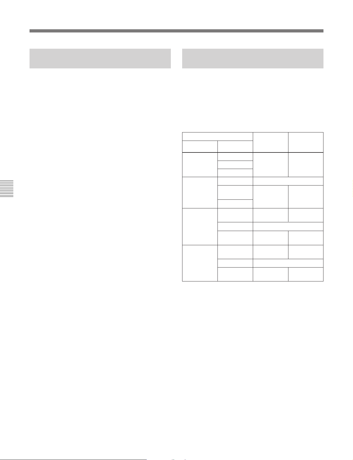
5-6 Points to Remember About Editing
5-6-4 Limitations When Editing
With MASTER as Player
Player IN and OUT points cannot be located in
different files.
When you execute an edit without setting an OUT
point, the edit ends automatically at the end point of
the player (MASTER) file. Continuous editing of
several files is not possible.
Multi-event editing
Events can be registered in different files, but a single
event cannot extend across different files.
Chapter 5 Editing Using the Built-in Hard Disk
5-6-5 Control of the Audio and
Video Recording Levels
During execution of an automatic edit, you can control
the audio recording level and video recording level by
rotating the REC and VIDEO knobs on the upper
control panel and the VIDEO knob on the subsidiary
control panel. The following table shows the knobs
employed, according to the device specification and
the signals controlled.
c)
d)
e)
Video
recording
level
Subsidiary
c)
panel
Subsidiary
panel
Subsidiary
d)
panel
Subsidiary
panel
Subsidiary
e)
panel
Device specification
Player Recorder
a)
EXT
TAPE TAPE Editing not possible
PROGRAM TAPE
MASTER TAPE REC knob
TAPE REC knob VIDEO knob
MASTER
PROGRAM
MASTER REC knob
PROGRAM
MASTER Editing not possible
PROGRAM REC knob
MASTER Editing not possible
PROGRAM REC knob
Audio
recording
level
REC knob
a) Only when external input is other than SDDI.
b) Only when composite video input signals are selected.
Otherwise control is not possible.
c) Only when using Betacam or Betacam SP tape.
Otherwise control is not possible.
d) Control is possible only during editing in SELF mode
started by pressing the EVENT button and the AUDIO
EDIT button simultaneously on Version 2.00 or later
units.
In this case, by setting extended menu items 321 and 322
to EXT, you can control signals re-input via external
devices such as a video effector and an audio mixer.
e) Control is possible only during editing started by pressing
the EVENT button and the AUDIO EDIT button
simultaneously on Version 2.00 or later units.
In this case, by setting extended menu items 321 and 322
to EXT, you can control signals re-input via external
devices such as a video effector and an audio mixer.
b)
5-22 Chapter 5 Editing Using the Built-in Hard Disk
Page 81
6-1 Automatic Editing
.
Chapter 6 Editing Without Using the Built-in Hard Disk (Two-VTR Editing)
This section describes how to carry out automatic
editing using the VTR built into the unit and an
external VTR connected to the unit using the
REMOTE-IN(9P) connector.
6-1-1 Overview
Editing mode
Editing with the VTR built into the unit and an
external VTR is always carried out as assemble
editing. This is the editing mode in which successive
portions of the edited result are recorded on the end of
the already completed section. The CTL signal, video
signal, audio signal, and timecode are all newly
recorded on the tape.
Using CTL to interpolate timecode values
When you are using timecode values as edit point
addresses, the timecode must be recorded on the tape
in correct time sequence (i.e. the sections must be in
strictly ascending time order).
If the timecode values are all in correct time sequence,
then if there are any discontinuities in the timecode,
the unit allows them to be interpolated using the CTL
counter.
Sequence of editing operations
The following flowchart outlines the sequence of
operations in automatic editing with two VTRs.
Setting the recorder and player edit points
(page 6-3)
.
Previewing the edit segments
(page 6-6)
.
Amending edit points as necessary
(page 6-4)
.
Carrying out the edit
(page 6-8)
.
Checking the editing results as necessary
(page 6-8)
Notes on video output to the monitor
In E-E mode, the video output of the unit is delayed by
the time for video circuit processing with respect to the
input video signal.
For playback to be carried out in editing mode with
both the player and recorder specified, you can use
extended menu item 701 to delay the V-SYNC phase,
aligning it with the video output of the unit. (This is
not possible for playback operations described in
Chapter 4, “Recording and Playback”.)
Chapter 6 Editing Without Using the Built-in Hard Disk (Two-VTR Editing)
Recording timecode
For automatic editing, regardless of the settings of the
INT/EXT switch and PRESET/REGEN switch,
timecode is recorded continuously from the previous
timecode recorded on the tape. Using extended menu
item 610, it is also possible to record time code
according to the settings in the time code setting
section on the lower control panel.
Chapter 6 Editing Without Using the Built-in Hard Disk (Two-VTR Editing) 6-1
Page 82
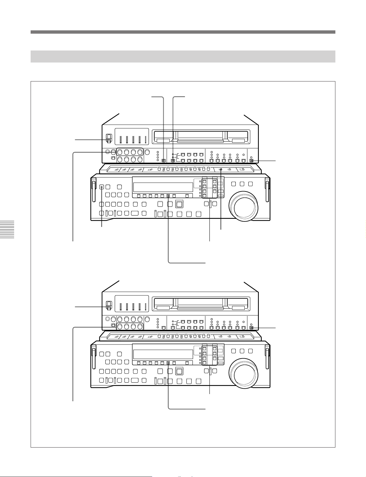
6-1 Automatic Editing
6-1-2 Switch Settings
Before beginning editing, set the switches as follows.
VIDEO INPUT SELECT switch (see
page 2-3): select the input video signal
POWER switch:
ON
ASSEMBLE/ALL button (see page 2-8):
Chapter 6 Editing Without Using the Built-in Hard Disk (Two-VTR Editing)
REC controls (see page 2-3):
adjust the audio recording levels
(see page 4-2)
lit
Audio selection function selector switch (see page 2-3):
select the input audio signal
Recorder
REMOTE/LOCAL
switch (see page 2-7):
9P indicator off
REC INHIBIT switch (see page 2-21): OFF
Device specification buttons (see page 2-12):
• RECORDER: TAPE
• PLAYER: EXT
CTL/TC/UB button (see page 2-9): TC
or CTL
POWER switch:
ON
PB controls (see page 2-5):
adjust the audio playback
levels
6-2 Chapter 6 Editing Without Using the Built-in Hard Disk (Two-VTR Editing)
Player
(DNW-A100/A100P)
REMOTE/
LOCAL switch
(see page 2-7):
9P indicator lit
Device specification buttons (see page 2-12):
RECORDER n TAPE
CTL/TC/UB button (see page 2-9): TC or CTL
Page 83
6-1-3 Setting Edit Points
Set the edit points for assemble editing between the
recorder and player.
To set an edit point
132
1 Press the RECORDER button or PLAYER button
to select the VTR on which you will set the edit
point.
The button which you have pressed lights.
Automatic setting of edit points
Editing requires four edit points: the IN and OUT
points on both the recorder and player. However, once
any three of these points are defined, the last point is
set automatically. For example, if you set the recorder
IN and OUT points, and the player IN point, the player
OUT point is set automatically.
Note
In the following cases, the DELETE button begins to
flash and you cannot carry out automatic editing.
•The OUT point is before the IN point.
•All four of the recorder IN and OUT points and the
player IN and OUT points have been set.
Use the DELETE button to delete a redundant edit
point, or set the edit points correctly.
For details of deleting edit points, see the section
“Deleting an edit point” (page 6-5).
To display the time value for an edit point
You can display the time value for an edit point in the
device specification and display section (see page
2-10). The IN point appears in time data display area
1, and the OUT point in time data display area 2.
Chapter 6 Editing Without Using the Built-in Hard Disk (Two-VTR Editing)
2 Turn the search dial in jog or shuttle mode, and
position the tape at the required edit point.
For details of playback in jog or shuttle mode, see the
sections “Playback in jog mode” (page 4-8) and
“Playback in shuttle mode” (page 4-9).
3 At the point at which you wish to set the IN point
or OUT point, hold down the ENTRY button and
press the IN button or OUT button as the case may
be.
When the IN point or OUT point is set, the IN
button or OUT button respectively lights.
4 Repeat steps 1 to 3 until all the necessary edit
points are set.
When the IN points on both the recorder and
player are set, the PREVIEW/REVIEW button and
AUTO EDIT button flash, and it becomes possible
to carry out a preview or editing operation.
Chapter 6 Editing Without Using the Built-in Hard Disk (Two-VTR Editing) 6-3
Time data display area 1
Time data display area 2
12
1 Press the RECORDER button or PLAYER button
to select the VTR on which you wish to check the
edit point.
The button you have pressed lights.
2 Hold down the IN button or OUT button according
to the edit point you wish to check.
While you hold down the button, the IN indicator
or OUT indicator of time data display area 1 or 2
lights, and the time value of the edit point is
displayed.
(Continued)
Page 84
6-1 Automatic Editing
To display the duration of an edit
You can display the duration between two edit points
in the following three cases, in the device specification
and display section (see page 2-10).
•When both the IN point and OUT point are set: the
duration of the segment between the two points
•When only one of the IN point and OUT point is set:
the duration of the segment between the point
which is set and the current tape position
•When neither of the IN point and OUT point is set:
the duration of the previous editing segment
The duration is displayed across time data display
areas 1 and 2, thus: “DURATION 00:01:10:00”.
To display a duration, use the following procedure.
1 Press the RECORDER button or PLAYER button
to select the VTR on which you wish to check the
duration.
The button you have pressed lights.
2 Hold down both the IN button and OUT button.
6-1-4 Modifying and Deleting
Edit Points
If the edit points are not set correctly, for example if an
OUT point is before a corresponding IN point, the
DELETE button flashes, and it is not possible to carry
out a preview or editing operation. In this case, either
modify the erroneous edit point, or first delete it and
then enter it correctly.
Modifying an edit point
To modify an edit point, use the following procedure.
Time data display area 1
Time data display area 2
Chapter 6 Editing Without Using the Built-in Hard Disk (Two-VTR Editing)
While you hold down the buttons, the duration is
displayed across time data display areas 1 and 2.
132
1 Press the RECORDER button or PLAYER button
to select the VTR on which you wish to modify the
edit point.
The button you have pressed lights.
2 Hold down the IN button or OUT button according
to the edit point you wish to modify, and turn the
search dial as follows:
•To advance the edit point: the FORWARD
direction
•To delay the edit point: the REVERSE direction
The time value for the IN or OUT point displayed
in time data display area 1 or 2 increases or
decreases according to the direction in which you
turn the search dial.
3 When the modification is completed, release the
6-4 Chapter 6 Editing Without Using the Built-in Hard Disk (Two-VTR Editing)
button you pressed in step 2.
Page 85
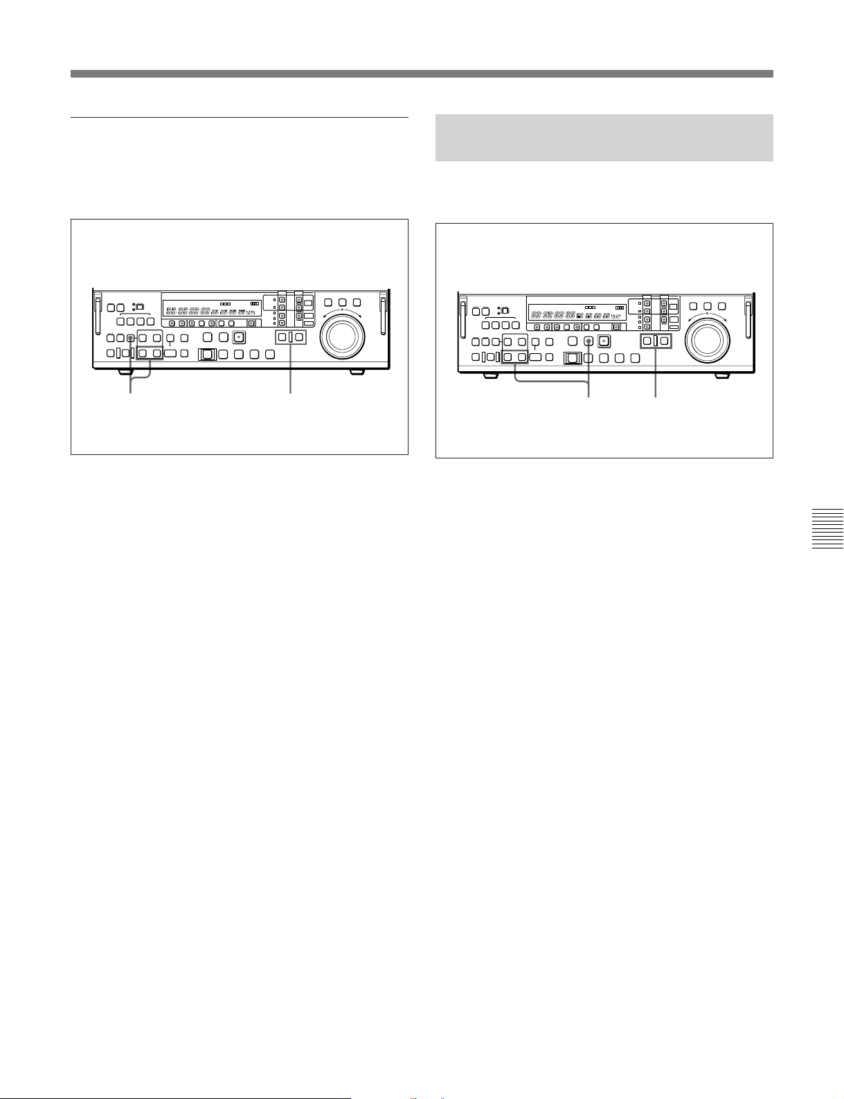
Deleting an edit point
To delete an edit point, use the following procedure.
You can use the same procedure whether or not the
DELETE button is flashing.
6-1-5 Cue-up to Edit Points and
Preroll
To preroll to an edit IN point or cue up to any edit
point, use the following procedure.
12
1 Press the RECORDER button or PLAYER button
to select the VTR on which you wish to delete the
edit point.
The button you have pressed lights.
2 Hold down the DELETE button and press the IN
button or OUT button according to the edit point
you wish to delete.
The IN point or OUT point is deleted according to
which button you pressed, and the DELETE button
goes off.
To restore a deleted edit point
To restore an edit point immediately after deleting it,
hold down the IN button or OUT button according to
the edit point you wish to restore, and press the
RECALL button.
12
1 Press the RECORDER button or PLAYER button
to select the VTR on which you wish to operate.
The button you have pressed lights.
Chapter 6 Editing Without Using the Built-in Hard Disk (Two-VTR Editing)
2 • To cue up to an edit point
Hold down the IN button or OUT button
according to the edit point to which you wish to
cue up, and press the PREROLL button.
This cues up to the edit point you have selected.
•To preroll
Press the PREROLL button.
The tape is wound back to a position 5 seconds
before the edit IN point, and stops.
To change the preroll time
The factory default setting for the preroll time is 5
seconds, but you can use basic menu item 001 to
change this to any value from 0 to 30 seconds. If you
change the preroll time, make sure that the setting is
not longer than the recording length before the edit IN
point.
Note that for automatic editing, the preroll time setting
on the recorder takes precedence.
For more information about the basic menu, see Section 7-2,
“Basic Menu” (page 7-1).
Chapter 6 Editing Without Using the Built-in Hard Disk (Two-VTR Editing) 6-5
Page 86
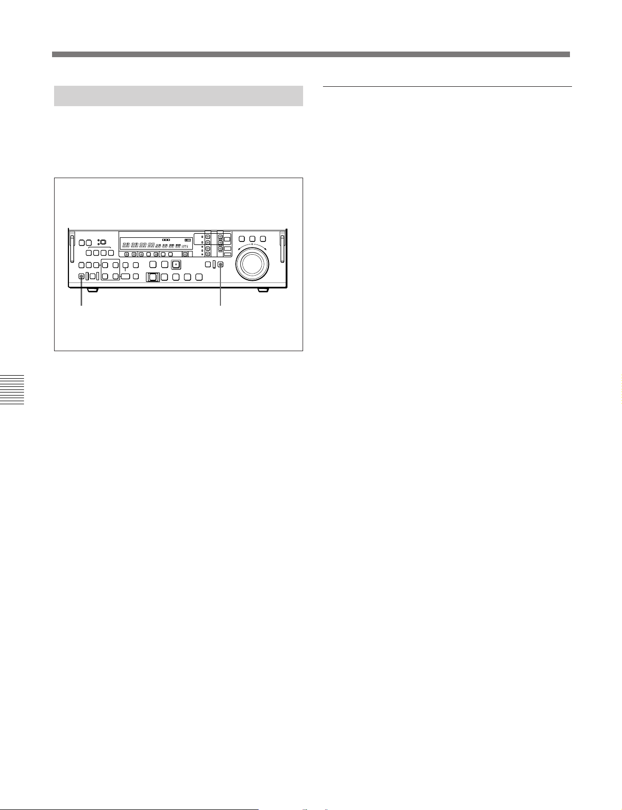
6-1 Automatic Editing
6-1-6 Preview
When you have set the edit points, the PREVIEW/
REVIEW button flashes, indicating that you can carry
out a preview.
To carry out a preview, use the following procedure.
2 1
1 Press the RECORDER button, turning it on.
Monitor output
During a preview, you can monitor the playback video
on a monitor connected to the recorder. The type of
video depends on the current settings.
For details, see the table “Monitor output video during
previews and editing” in Section 5-2-9 “Preview”, referring
to the case when the player is EXT and the recorder is
TAPE.
2 Press the PREVIEW/REVIEW button.
Chapter 6 Editing Without Using the Built-in Hard Disk (Two-VTR Editing)
The PREVIEW/REVIEW button changes from
flashing to continuously lit, and the preview is
carried out.
At the end of the preview, the PREVIEW/
REVIEW button goes off.
To stop the preview
Press the STOP button.
The tape stops at the position where you pressed
the button.
To return the tape to the preroll point
Press the PREROLL button.
To return the tape to the IN point or OUT point
Press the PREROLL button and the IN button or OUT
button simultaneously.
After the preview, make adjustments to the edit points,
then repeat the preview as necessary.
For details of how to modify or delete edit points, see
Section 6-1-4, “Modifying and Deleting Edit Points” (page
6-4).
6-6 Chapter 6 Editing Without Using the Built-in Hard Disk (Two-VTR Editing)
Page 87
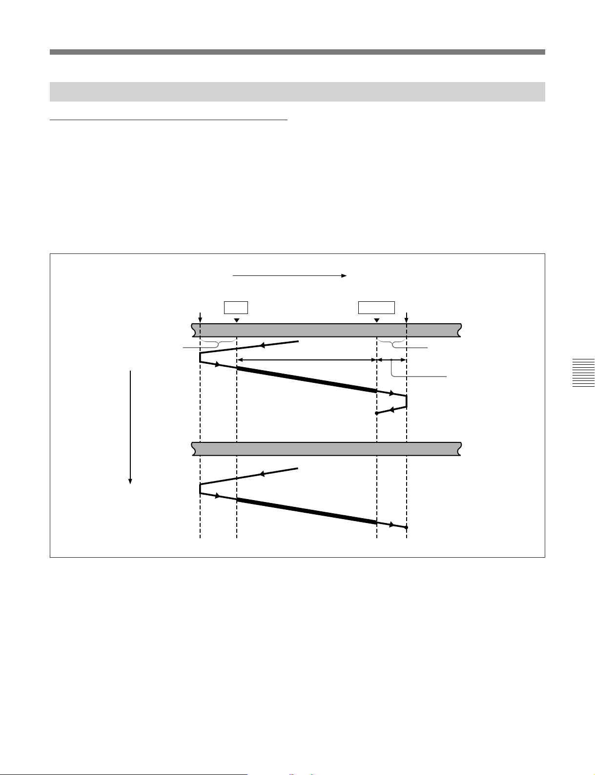
6-1-7 Carrying Out Automatic Editing
Overview
When you carry out automatic editing, the recorder
and player operate as shown in the following figure, to
copy the video and audio signals between the IN and
OUT points on the player to the segment between the
IN and OUT points on the recorder.
Preroll point
Recorder
Preroll
IN point
Monitor output
During execution of an automatic edit, you can
monitor the playback video on a monitor connected to
the recorder. The type of video depends on the current
settings.
For details, see the table “Monitor output video during
previews and editing” in Section 5-2-9 “Preview”, referring
to the case when the player is EXT and the recorder is
TAPE.
Tape transport
OUT point
Assemble editing
Postroll point
Postroll
Recording
overlap
Chapter 6 Editing Without Using the Built-in Hard Disk (Two-VTR Editing)
Time flow
Player
Playback
Stop
Stop
Chapter 6 Editing Without Using the Built-in Hard Disk (Two-VTR Editing) 6-7
Page 88

6-1 Automatic Editing
Starting automatic editing
When you have set the edit points, press the flashing
AUTO EDIT button.
The AUTO EDIT button changes from flashing to
continuously lit, and the automatic editing operation
begins.
At the end of the editing operation, the AUTO EDIT
button goes off.
RECALL button
ENTRY button
OUT button
AUTO EDIT button
PREVIEW/REVIEW button
Reviewing the editing results
After carrying out an editing operation, you can carry
out a review, to check the editing results on the
monitor.
To carry out a review, after carrying out the edit, and
before you set any new edit points or make other
settings, press the PREVIEW/REVIEW button.
The PREVIEW/REVIEW button lights, and the review
is carried out.
At the end of the review the PREVIEW/REVIEW
button goes off, and the tape returns to the OUT point.
After automatic editing, to adjust the edit
points and reexecute the edit
Hold down the RECALL button or DELETE button,
and press the ENTRY button to recall the edit points.
After adjusting the edit points, press the AUTO EDIT
button to carry out the edit again.
For details of how to adjust edit points, see Section 6-1-4,
“Modifying and Deleting Edit Points” (page 6-4).
Chapter 6 Editing Without Using the Built-in Hard Disk (Two-VTR Editing)
To change the OUT point after starting
automatic editing operation
After starting the automatic editing operation, to end
the operation before the preset OUT point, hold down
the ENTRY button and press the OUT button.
The position where you pressed the button becomes
the OUT point, and editing ends.
To abandon automatic editing
Press the STOP button.
The automatic editing operation is abandoned. At the
same time, the PREVIEW/REVIEW button and
AUTO EDIT button start flashing, and the state before
the editing was started is restored.
In this case, the IN and OUT points already set are
preserved so that you can carry out a preview or
automatic editing operation again by pressing the
PREVIEW/REVIEW button or AUTO EDIT button.
6-8 Chapter 6 Editing Without Using the Built-in Hard Disk (Two-VTR Editing)
Page 89
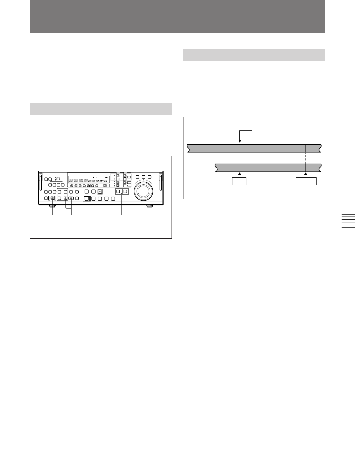
6-2 Special Automatic Editing Methods
This section describes the following automatic editing
methods:
•Quick editing
•Continuous editing
•Standalone editing
6-2-1 Quick Editing
After selecting the edit mode, you can save on editing
time by setting the edit points and executing the edit at
the same time.
For quick editing, use the following procedure.
2 13
6-2-2 Continuous Editing
After an automatic editing operation, the recorder
automatically returns to the OUT point. For the
second and subsequent editing operations, you can
continue editing by simply specifying the IN and OUT
points on the player. In this case the current OUT
point on the recorder becomes the new IN point.
Previous OUT point =
Recorder
Previous editing segment
Player
IN point
After automatic editing of one edit segment, to carry
out continuous editing use the following procedure.
next IN point
Next editing segment
OUT point
1 When operating the player, press the PLAYER
button, turning it on, and when operating the
recorder, press the RECORDER button, turning it
on, then stop the tapes on both the player and the
recorder at the positions you wish to make the
respective IN points.
2 Press the AUTO EDIT button.
Editing starts.
3 Watching the editing on the monitor, at the
position you wish to make the OUT point, hold
down the ENTRY button and press the OUT
button.
Editing ends.
The point at which you started the editing becomes
the IN point, and the point at which you ended the
editing becomes the OUT point.
1 Set the player IN and OUT points.
On the recorder the OUT point for the previous
edit becomes the new IN point.
2 Press the PREVIEW/REVIEW button to carry out
a preview.
3 Press the AUTO EDIT button.
This executes the edit.
When the editing operation is completed, the
recorder stops at the OUT point, and the player
stops 2 seconds after the OUT point.
By repeating this process, you can carry out
continuous editing.
Chapter 6 Editing Without Using the Built-in Hard Disk (Two-VTR Editing)
If you want to preview
In step 1, after setting the recorder or player IN point,
press the PREVIEW/REVIEW button.
Chapter 6 Editing Without Using the Built-in Hard Disk (Two-VTR Editing) 6-9
Page 90

6-2 Special Automatic Editing Methods
6-2-3 Standalone Editing
This refers to editing using as the player an external
device which cannot be controlled remotely through
the REMOTE-IN(9P) connector. For example, you
can record a color bar signal from a signal generator in
the joints between the events of an already completed
program.
Carrying out standalone editing
To carry out standalone editing, specify EXT as the
player and TAPE as the recorder.
First use the VIDEO INPUT SELECT switch to select
the signal being generated by the signal generator
connected to the unit, then with both the PLAYER
button and RECORDER button off (the SELF mode),
set the IN point.
The AUTO EDIT button flashes, and it is now possible
to carry out automatic editing.
If necessary, you can also first set the OUT point.
Chapter 6 Editing Without Using the Built-in Hard Disk (Two-VTR Editing)
6-10 Chapter 6 Editing Without Using the Built-in Hard Disk (Two-VTR Editing)
Page 91
7-1 Menu System Configuration
Chapter 7 Menu System
The menu system of this unit comprises the basic
menu, extended menu and disk file management menu.
•Basic menu
This menu is used to make settings relating, for
example, to the following.
-the hours meter
-the preroll time
-the character information superimposed on the
output to the monitor
-switching between the 525/60 (NTSC) system and
625/50 (PAL) system
-the menu banks for retaining menu settings
7-2 Basic Menu
7-2-1 Items in the Basic Menu
For detailed information about menu operation relating to
the hours meter, see Section 8-5 “Digital Hours Meter”
(page 8-3).
•Extended menu
This menu is used to make a wide range of settings
relating to the functions of this unit, for example, the
control panel functions, video and audio control, and
digital data processing.
•Disk file management menu
This menu is used to make settings relating to the
creation and management of files on the built-in hard
disk.
The basic menu contains the following items.
default settings are indicated by an enclosing box.
In the “Settings” column of the table, the factory
Item number Item name Settings
001 PREROLL TIME 0S ... 5S ... 30S: Set the preroll time to between 0 and 30 seconds. A preroll time
a)
002
a), b)
003
004 SYCHRONIZE When editing using this unit as a controller and an external VTR connected to this
a) When setting items 002, 003, 009, and 011, watch the
monitor screen, and adjust to the required state.
CHARACTER HPOSITION
CHARACTER VPOSITION
of at least 5 seconds is recommended when using this unit for editing.
Adjust the horizontal screen position of the character information output from the
COMPOSITE VIDEO OUTPUT 3 (SUPER) connector for superimposed display
on the monitor.
00 ... 14 ... 24 (525 mode)/00 ... 12 ... 22 (625 mode): The hexadecimal value 00
is for the far left of the screen and 24 (decimal 36) for the far right. Increasing
the value moves the position of the characters to the right.
Adjust the vertical screen position of the first line of the characters information
output from the COMPOSITE VIDEO OUTPUT 3 (SUPER) connector for
superimposed display on the monitor.
00 ... 56 ... 6A (525 mode)/00 ... 6A ... 81 (625 mode): The hexadecimal value
00 is for the top of the screen and 6A (decimal 106) for the bottom. Increasing
the value lowers the position of the characters.
unit via a 9-pin remote control cable, this item determines whether or not to
operate the two units in phase synchronization.
ON : Operate in phase synchronization.
OFF: Do not operate in phase synchronization.
b) When displaying time code values, there is a slight time
delay. Therefore, when creating a tape for off-line
editing, the information inserted in the upper half of the
screen may be delayed by one frame.
Chapter 7 Menu System
(Continued)
Chapter 7 Menu System 7-1
Page 92
7-2 Basic Menu
Item number Item name Settings
005 DISPLAY INFORMATION
006 LOCAL FUNCTION
007 TAPE TIMER DISPLAY Determines whether to display the CTL count in 12-hour mode or 24-hour mode.
008 MONITORING
009
011
Chapter 7 Menu System
a) When setting items 002, 003, 009, and 011, watch the
SELECT
ENABLE
SELECTION FOR VTRTO-VTR EDIT
a)
a)
CHARACTER TYPE Determines the type of characters such as time code output from the
CHARACTER V-SIZE Determines the vertical size of characters such as time code output from the
Determines the kind of character information to be output from the COMPOSITE
VIDEO OUTPUT 3 (SUPER) connector when the CHARACTER switch on the
subsidiary control panel is set to ON.
T&STA : Time data display information and the unit’s status.
T&UB: Time data display information and the user’s bits.
T&CTL: Time data display information and CTL.
T&T: Time data display information and time code (LTC or VITC).
TIME: Time code (LTC or VITC) only.
If there is a overlap between the setting of this item and the setting of the control
panel, it is automatically avoided. For example, if CTL is selected on the control
panel and this menu item setting is T&CTL, then CTL and LTC are output.
Determines which buttons on the control panel are enabled when this unit is
controlled from external equipment.
DIS: All buttons and switches are disabled.
ST&EJ : Only the STOP button and EJECT button are enabled.
ENA: All buttons and switches except the RECORDER button and PLAYER
button are enabled.
+ –12H: 12-hour mode
24H: 24-hour mode
For recorder-player editing with only one monitor connected to the recorder,
determines whether the recorder is forced into E-E mode when the recorder’s
PLAYER button is pressed to view the player’s playback signals on the monitor.
MANU: Do not force the recorder into E-E mode.
AUTO: Force the recorder into E-E mode.
COMPOSITE VIDEO OUTPUT 3 (SUPER) connector for superimposed display
on the monitor.
WHITE: White letters on a black background.
BLACK: Black letters on a white background.
W/OUT: White outline letters.
B/OUT: Black outline letters.
COMPOSITE VIDEO OUTPUT 3 (SUPER) connector for superimposed display
on the monitor.
×1: Standard size
×2: 2 times standard size
×3: 3 times standard size
×4: 4 times standard size
monitor screen, and adjust to the required state.
7-2 Chapter 7 Menu System
Page 93
Item number Item name Settings
013 525/625 SYSTEM
SELECT
Specify whether to enable switching between the 525 (NTSC) and 625 (PAL)
systems.
OFF: Do not enable system switching.
Before using this menu
item, consult the person
responsible for the
ON: Enable system switching.
Setting this item to ON and switching the system enables the unit to operate in
the system switched to.
installation.
The basic and extended menu settings are saved separately for 525 (NTSC)
mode and 625 (PAL) mode.
Limitations when using the DNW-A100/A50/A45 in 625 mode
• Betacam and Betacam SP tape cannot be played back.
• Composite input cannot be recorded.
• When NTSC signals are recorded on the hard disk, the hard disk cannot be
used for recording or playback. In this case, HD525 is displayed in the time data
display area. In order to use the hard disk again, use the disk file management
(see page 7-25)
menu
to delete all files.
• Color frame synchronization with external reference video signals cannot be
performed.
Limitations when using the DNW-A100P/A50P/A45P in 525 mode
• Betacam and Betacam SP tape cannot be played back.
• Composite input cannot be recorded.
• When PAL signals are recorded on the hard disk, the hard disk cannot be used
for recording or playback. In this case, HD625 is displayed in the time data
display area. In order to use the hard disk again, use the disk file management
(see page 7-25)
menu
to delete all files.
• Color frame synchronization with external reference video signals cannot be
performed.
B01 RECALL BANK 1 Set to ON to recall menu settings from menu bank 1.
B02 RECALL BANK 2 Set to ON to recall menu settings from menu bank 2.
B03 RECALL BANK 3 Set to ON to recall menu settings from menu bank 3.
B04 RECALL BANK 4 Set to ON to recall menu settings from menu bank 4.
B11 SAVE BANK 1 Set to ON to save current menu settings to menu bank 1.
B12 SAVE BANK 2 Set to ON to save current menu settings to menu bank 2.
B13 SAVE BANK 3 Set to ON to save current menu settings to menu bank 3.
B14 SAVE BANK 4 Set to ON to save current menu settings to menu bank 4.
B20 RESET SETUP Set to ON to reset current active settings to factory default values.
Chapter 7 Menu System
Chapter 7 Menu System 7-3
Page 94

7-2 Basic Menu
This section describes the basic menu displays and
how to change the settings.
For information about how to use item 013, see the section
“Switching between 525/625 line systems (menu item 013)”
(page 7-6), and for information about how to use items B01
to B14, see the section “Menu bank operations (menu items
B01 to B14” (page 7-8).
Displaying the menus
Press the MENU button, turning it on.
Chapter 7 Menu System
The F FWD button and VAR button light, and the
setting of the currently selected menu item appears in
the time data display.
7-2-2 Basic Menu Operations
VAR button
Time data display
F FWD button
MENU button
To display the full item name
Hold down the F FWD button.
Item name (all characters)
To display the item group name
Items in the menu are arranged in groups, by the 100’s
digit of the item number. To display the name of the
group to which the currently selected item belongs,
hold down the VAR button.
Item group name
Output from COMPOSITE VIDEO OUTPUT 3
(SUPER) connector
If the CHARACTER switch on the subsidiary control
panel is set to ON, then when you display a menu item
on the time data display, a full-screen version also
appears on a monitor connected to the COMPOSITE
VIDEO OUTPUT 3 (SUPER) connector as shown in
the following figure.
Group name for the
currently selected
item
Cursor indicating the
currently selected
item
*HO1:OPE HOURS - 102
HO2:DRUM HOURS - 52
HOURS METER
-------
Item number
(flashing)
Item name
(first three characters)
7-4 Chapter 7 Menu System
Setting
Page 95
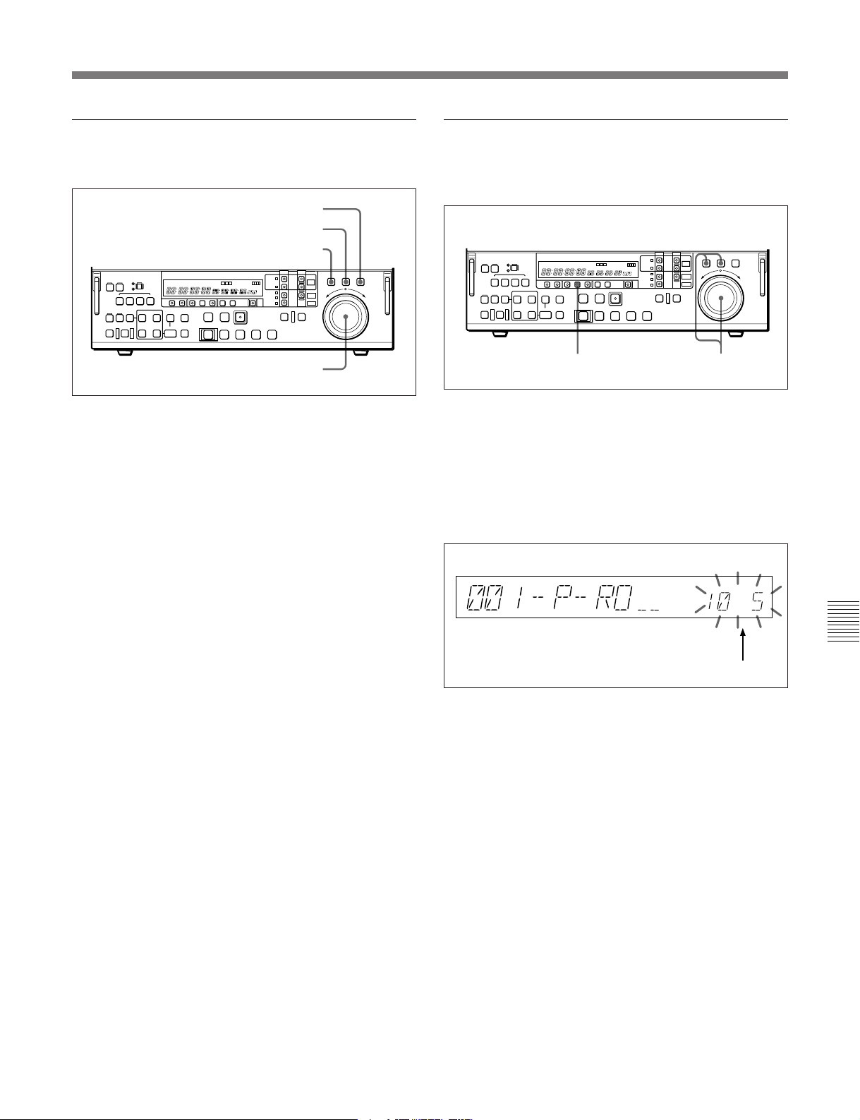
Changing the currently displayed menu
item
VAR button
JOG button
SHUTTLE button
Changing a menu item setting value
To change the setting value of the currently displayed
menu item, use the following procedure.
Search dial
Turn the search dial.
Turning the search dial in the forward direction
increments the item number, and turning it in the
reverse direction decrements the item number.
If you press the SHUTTLE button or JOG button,
turning it on, then turn the search dial, the item number
changes at a rate depending on the search dial position
(when the SHUTTLE button is lit) or on the search
dial rotation rate (when the JOG button is lit).
To skip from one item group to the next
Hold down the VAR button, and turn the search dial.
12
1 Holding down the SHUTTLE button or JOG
button, turn the search dial.
The setting value changes at a rate depending on
the search dial position (when the SHUTTLE
button is lit) or on the search dial rotation rate
(when the JOG button is lit).
Chapter 7 Menu System
Setting value (flashes while changing)
2 When the desired setting value is displayed, press
the SET button.
This saves the new setting value, and the menu
display disappears from the time data display.
To abandon making a change
Press the MENU button before pressing the SET
button.
The menu display disappears from the time data
display, without the new setting value being saved.
Chapter 7 Menu System 7-5
Page 96
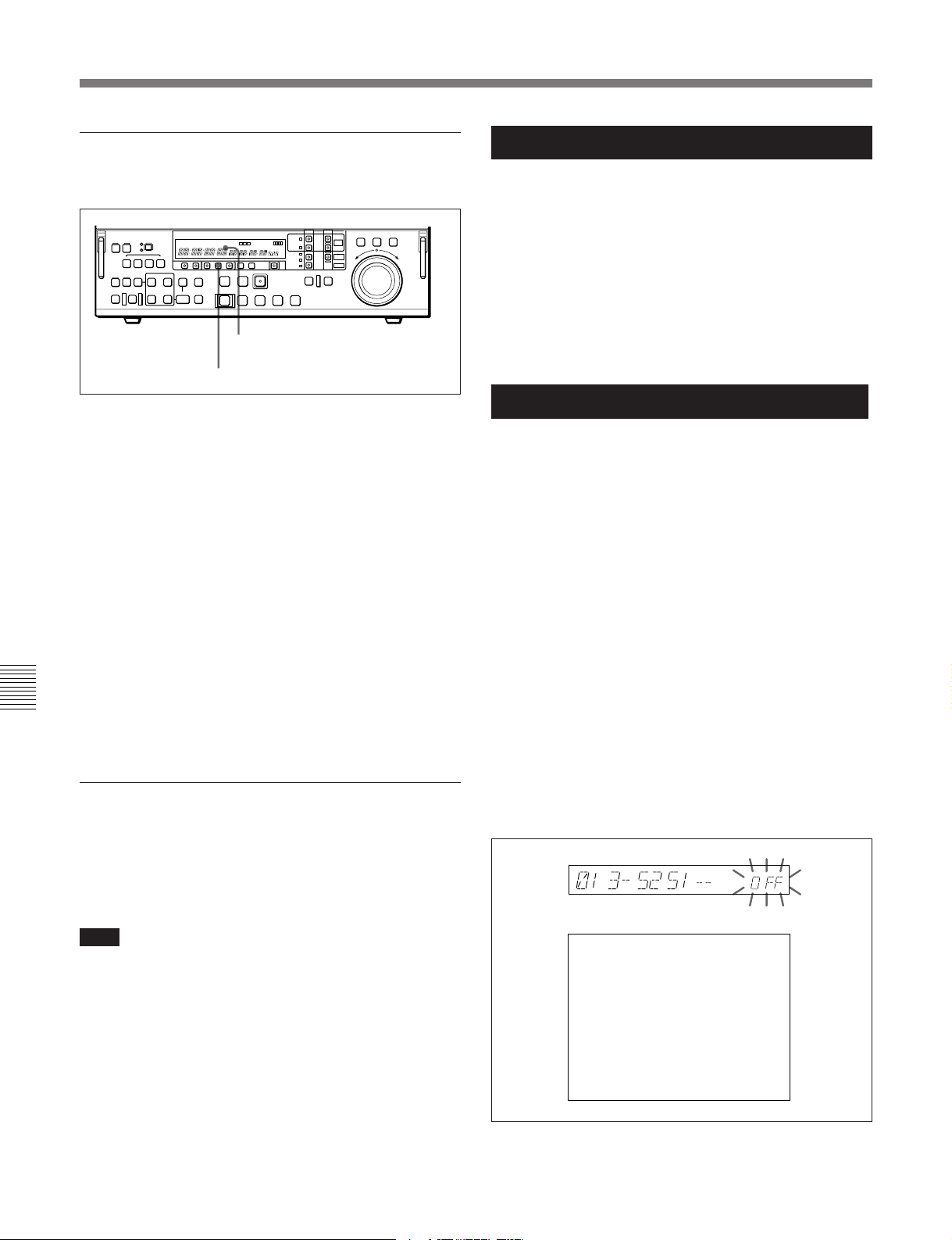
7-2 Basic Menu
Resetting the menu settings to their
factory default values (menu item B20)
Time data display
SET button
1 Set menu item B20 RESET SETUP to ON.
“PUSH SET BTN” appears in the time data
display, and “Push SET button” appears on the
monitor screen.
2 Press the SET button.
The current active menu settings (see page 7-8) are
reset to their factory default settings.
Limitations when using the DNW-A100/A50/A45 in 625
mode
•Betacam and Betacam SP tape cannot be played back.
•Composite input cannot be recorded.
•When NTSC signals are recorded on the hard disk,
the hard disk cannot be used for recording or
playback. In this case, HD525 is displayed in the time
data display area. In order to use the hard disk again,
use the disk file management menu (see page 7-25) to
delete all files.
•Color frame synchronization with external reference
video signals cannot be performed.
Limitations when using the DNW-A100P/A50P/A45P in
525 mode
•Betacam and Betacam SP tape cannot be played back.
•Composite input cannot be recorded.
•When PAL signals are recorded on the hard disk, the
hard disk cannot be used for recording or playback.
In this case, HD625 is displayed in the time data
display area. In order to use the hard disk again, use
the disk file management menu (see page 7-25) to
delete all files.
•Color frame synchronization with external reference
video signals cannot be performed.
3 Press the SET button again.
Chapter 7 Menu System
Switching between 525/625 line systems
(menu item 013)
Using the following procedure, you can set basic menu
item 013, 525/625 SYSTEM SELECT, to “ON”, and
then switch between 525 (NTSC) and 625 (PAL).
Note
Before carrying out this operation, consult the person
responsible for the installation.
The settings are saved and the menu display
disappears from the time data display.
(The following procedure shows by way of example
how to switch from a 525 (NTSC) system to a 625
(PAL) system.)
1 Select menu item 013.
The time data display and the monitor screen
connected to the COMPOSITE VIDEO OUTPUT
3 (SUPER) connector show the following displays.
Time data display
Monitor screen
ITEM-013
525/625 SYSTEM
SELECT
OFF
7-6 Chapter 7 Menu System
Page 97
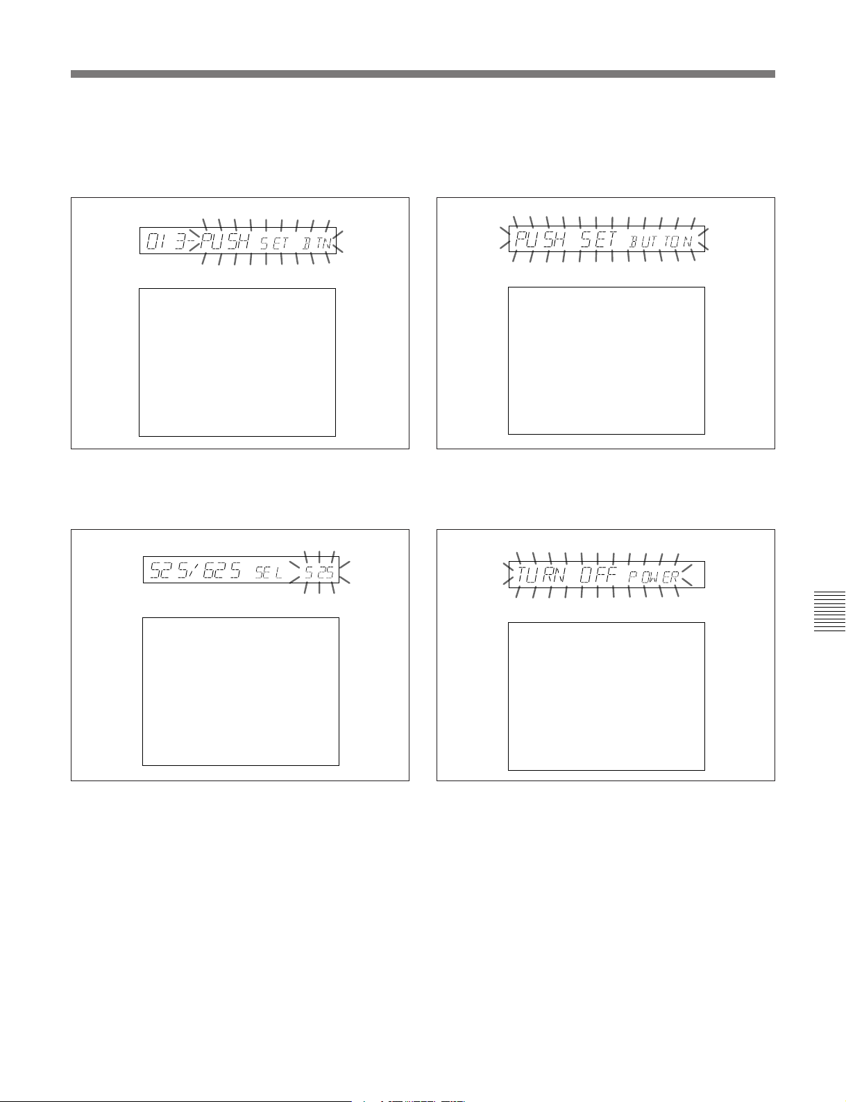
2 Holding down the JOG button, turn the search dial
to change the setting from “OFF” to “ON”.
4 Holding down the JOG button, turn the search dial
to change the setting from “525” to “625”.
The displays change as follows.
Time data display
Monitor screen
ITEM-013
525/625 SYSTEM
SELECT
Push SET button!!
3 Press the SET button.
The displays change as follows.
Time data display
The displays change as follows.
Time data display
Monitor screen
525/625 SYSTEM SELECT
625
Push SET button!!
ON
------ Caution -----All user data on the
disk will be lost.
5 Press the SET button.
The displays change as follows.
Time data display
Monitor screen
525/625 SYSTEM SELECT
525
If the 525/625 setting
is changed, turn power
off and on!
------ Caution -----All user data on the
disk will be lost.
Monitor screen
525/625 SYSTEM SELECT
625
Turn off/on POWER!!
------ Caution -----All user data on the
disk will be lost.
To abandon the 525/625 setting operation
Press the MENU button a required number of
times to exit from the menu.
6 Turn the POWER switch off momentarily, then on
again.
This switches from a 525 (NTSC) to 625 (PAL)
system; the 525 indicator goes off, and the 625
indicator lights.
The menu settings disappear from the time data
display, which returns to the normal indications.
Chapter 7 Menu System
Chapter 7 Menu System 7-7
Page 98

7-2 Basic Menu
Menu bank operations (menu items B01 to
B14)
This unit allows four different complete sets of menu
settings to be saved in what are termed “menu banks”
numbered 1 to 4. Saved sets of menu settings can be
recalled for use as required.
To jump to menu item B01
You can recall any required menu item by turning the
search dial after pressing the MENU button.
If you press the MENU button first, then the CTL/TC/
UB button, you can jump directly to menu item B01 or
H01. The recalled menu item toggles between B01
and H01 every time you press the CTL/TC/UB button.
Saving the current active menu settings
Set one of menu items B11 SAVE BANK 1 to B14
SAVE BANK 4 to ON, depending on which of the
menu banks you wish to save in, then press the SET
button.
Recalling settings from a menu bank
Set one of menu items B01 RECALL BANK 1 to B04
RECALL BANK 4 to ON, depending on which of the
menu banks you wish to recall from, then press the
SET button.
Chapter 7 Menu System
Current active
menu settings
Recall
Save
Recall
Save
Recall
Save
Menu bank 1
Menu bank 2
Menu bank 3
Recall
7-8 Chapter 7 Menu System
Save
Menu bank 4
Page 99
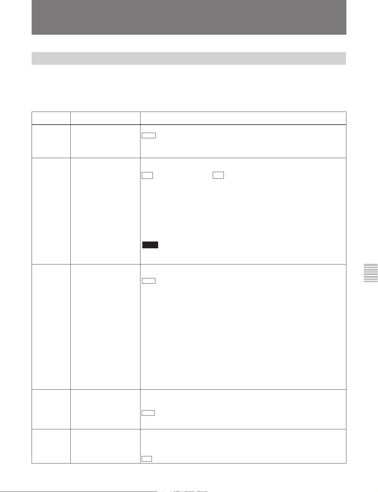
7-3 Extended Menu
7-3-1 Items in the Extended Menu
The extended menu contains the following items.
In the “Settings” column of the table, the factory
default settings are indicated by an enclosing box.
Menu items in the 100s, relating to the control panels
Item number
101 SELECTION FOR
102
(Before
Version 2.00)
102
(Version 2.00
or later)
Item name Settings
SEARCH DIAL ENABLE
MAXIMUM TAPE SPEED
(Enabled only when the
DNW-A100/A50/A45 is in
525 mode or the DNWA100P/A50P/A45P is in
625 mode.)
MAXIMUM SPEED
Select how the unit enters the search mode.
DIAL : Turning the search dial switches to search mode at all times except during
recording/editing.
KEY: One of the JOG, SHUTTLE, and VAR buttons must be pressed to switch to
search mode.
Select the maximum tape speed in the search mode when using an analog
cassette.
×35 (DNW-A100/A50/A45) / ×42 (DNW-A100P/A50P/A45P) : The maximum
speed for rewind and fast forward, and the maximum speed setting of the
search dial in shuttle mode is 35 times normal (DNW-A100/A50/A45) or 42
times normal (DNW-A100P/A50P/A45P).
×35/24 (DNW-A100/A50/A45) / ×42/24 (DNW-A100P/A50P/A45P): The
maximum speed for rewind and fast forward is 35 times normal (DNW-A100/
A50/A45) or 42 times normal (DNW-A100P/A50P/A45P), and the maximum
speed setting of the search dial in shuttle mode is 24 times normal.
×24: The maximum speed for rewind and fast forward, and the maximum speed
setting of the search dial in shuttle mode is 24 times normal.
Note
When using a digital cassette, regardless of this setting the maximum speed is 50
times normal.
Select the fast forward and rewind tape speed during tape playback, and the
search mode speed during playback from tape or hard disk.
MAX : Perform fast forward, rewind, and search mode playback at the maximum
speeds.
MX/24: Perform fast forward and rewind at the maximum speeds, and search
mode playback at up to 24 times normal speed.
×24: Perform fast forward and rewind at 24 times normal speed, and search
mode playback at up to 24 times normal speed.
Chapter 7 Menu System
Maximum fast forward and rewind speeds
• Analog cassette: 35 times (DNW-A100/A50/A45) or 42 times (DNW-A100P/
A50P/A45P) normal speed.
• Digital cassette: 80 times normal speed
Maximum search mode speeds
• Analog cassette: 35 times (DNW-A100/A50/A45) or 42 times (DNW-A100P/
A50P/A45P) normal speed.
• Digital cassette: 50 times normal speed
• Hard disk: 100 times normal speed
104 AUDIO MUTING TIME Select the length of time for which audio muting occurs when the unit switches to
playback either from stopped or from still playback in the search mode (for
Betacam compatible playback only).
OFF : Set the audio muting time to zero (i.e. no muting).
0.1S ... 1.0S: Set the audio muting time from 0.1 seconds to 1.0 second, in 0.1-
second increments.
105 REFERENCE SYSTEM
ALARM
Select whether or not to display a warning when the video/audio reference signal
selected by the OUT REF switch on the subsidiary control panel, is not supplied
or is out of phase with the input video signal.
OFF: No warning.
ON : Flash the STOP button as a warning.
(Continued)
Chapter 7 Menu System 7-9
Page 100
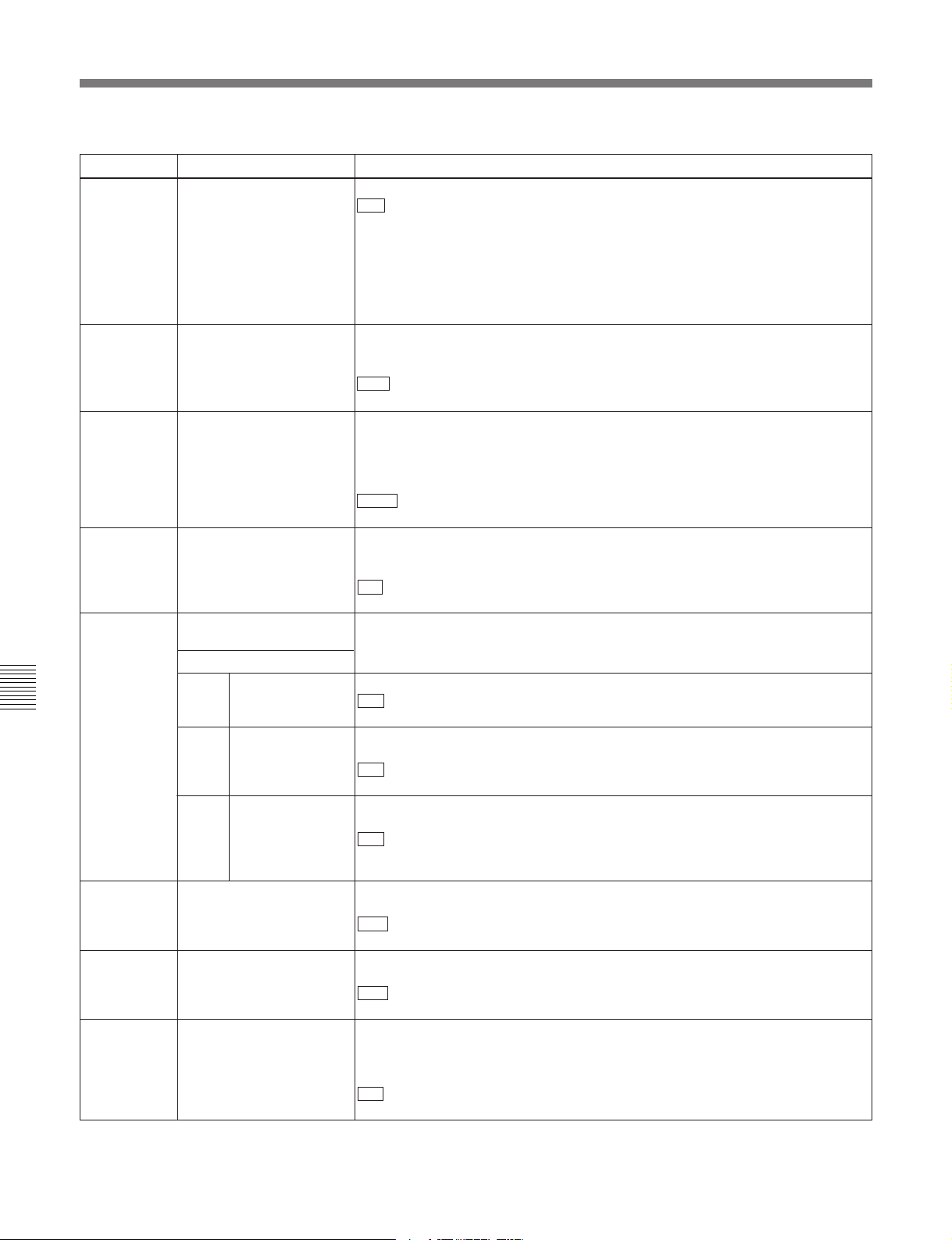
7-3 Extended Menu
Item number Item name
106 CAPSTAN LOCK Select the capstan servo lock mode.
107 REC INHIBIT LAMP
108 AUTO EE SELECT
109
118 KEY INHIBIT SWITCH
Chapter 7 Menu System
119 VARIABLE SPEED LIMIT
120 CTL LOCK IN VAR/SHTL Select whether the tape transport should be phase-locked to the CTL signal
122 AUTO EE WITH ANALOG
Menu items in the 100s, relating to the control panels (continued)
FLASHING
FORCED EE WHEN
TAPE UNTHREAD
EFFECTIVE AREA
Sub-item
118-1
118-2 MON./ INPUT
118-3 CONTROL
IN KEY PANEL CONTROL
TAPE
REMOTE
SELECT
SEL
PANEL
Settings
SW : The capstan servo lock mode is determined by the CAPSTAN LOCK switch
on the subsidiary control panel.
2F: The capstan servo locks every two fields regardless of the setting of the
CAPSTAN LOCK switch on the subsidiary control panel.
4F: The capstan servo locks every four fields regardless of the setting of the
CAPSTAN LOCK switch on the subsidiary control panel.
8F (For 625 mode only): The capstan servo locks every eight fields regardless of
the setting of the CAPSTAN LOCK switch on the subsidiary control panel.
Select whether or not to flash the REC INHIBIT indicator when the REC INHIBIT
switch on the subsidiary control panel is set to OFF and the REC inhibit plug on
the cassette is pressed in.
OFF : Do not flash the REC INHIBIT indicator.
ON: Flash the REC INHIBIT indicator.
When a digital cassette is inserted and the PB and PB.EE buttons on the lower
control panel are set to the PB/EE mode, select the VTR modes in which input
video and audio signals are automatically handled in EE mode.
When an analog cassette is inserted, regardless of the menu setting the PB mode
is always selected.
S/F/R : In STOP/EJECT/F.FWD/REW modes
STOP: In STOP/EJECT modes
During tape threading and unthreading, and when no cassette is inserted, select
whether the PB and PB.EE buttons on the lower control panel control the output
signal PB/EE setting.
ON : No control by the PB and PB.EE buttons (the signal is always an EE signal).
OFF: Control by the PB and PB.EE buttons.
Select which switches and buttons can be operated when the KEY INHIBIT
switch on the subsidiary control panel is set to ON. The following sub-items
control different sets of switches and buttons independently.
Select whether the REMOTE/LOCAL switch in the upper control panel is enabled.
DIS : Disabled.
ENA: Enabled.
Select whether the AUDIO INPUT / MONITOR SELECT buttons in the upper
control panel are enabled.
DIS : Disabled.
ENA: Enabled.
Select which switch and button operations can be carried out from the control
panel of this unit or an external control panel connected to this unit.
DIS : All switches and buttons are disabled.
EDIT: All switches and buttons for editing operations are disabled.
ENA: All switches and buttons are enabled.
Select the playback speed range when carrying out playback in variable mode
from the control panel of this unit.
OFF : –1 to +1 times normal speed.
ON: 0 to +1 times normal speed.
during playback in variable or shuttle mode.
OFF : Not phase-locked.
ON: Phase-locked at the following speeds: –1, –0.5, 0.5, and 1.0 times normal.
Select whether or not the setting of item 108 also applies to an analog cassette.
Item 108 selects the VTR modes in which input video and audio signals are
automatically handled in EE mode, when a digital cassette is inserted and the PB
and PB.EE buttons on the lower control panel are set to the PB/EE mode.
DIS : When an analog cassette is inserted, always use PB mode.
ENA: When an analog cassette is inserted, follow the setting of item 108.
7-10 Chapter 7 Menu System
 Loading...