

Sony SAT-B55, DirecTV SAT-A55, DirecTV SAT-B55, DirecTV SAN-18D3, DirecTV RM-Y802 Service Manual
...
SAT-A55 RM-Y802
SAT-B55 RM-Y139
SAN-18D3
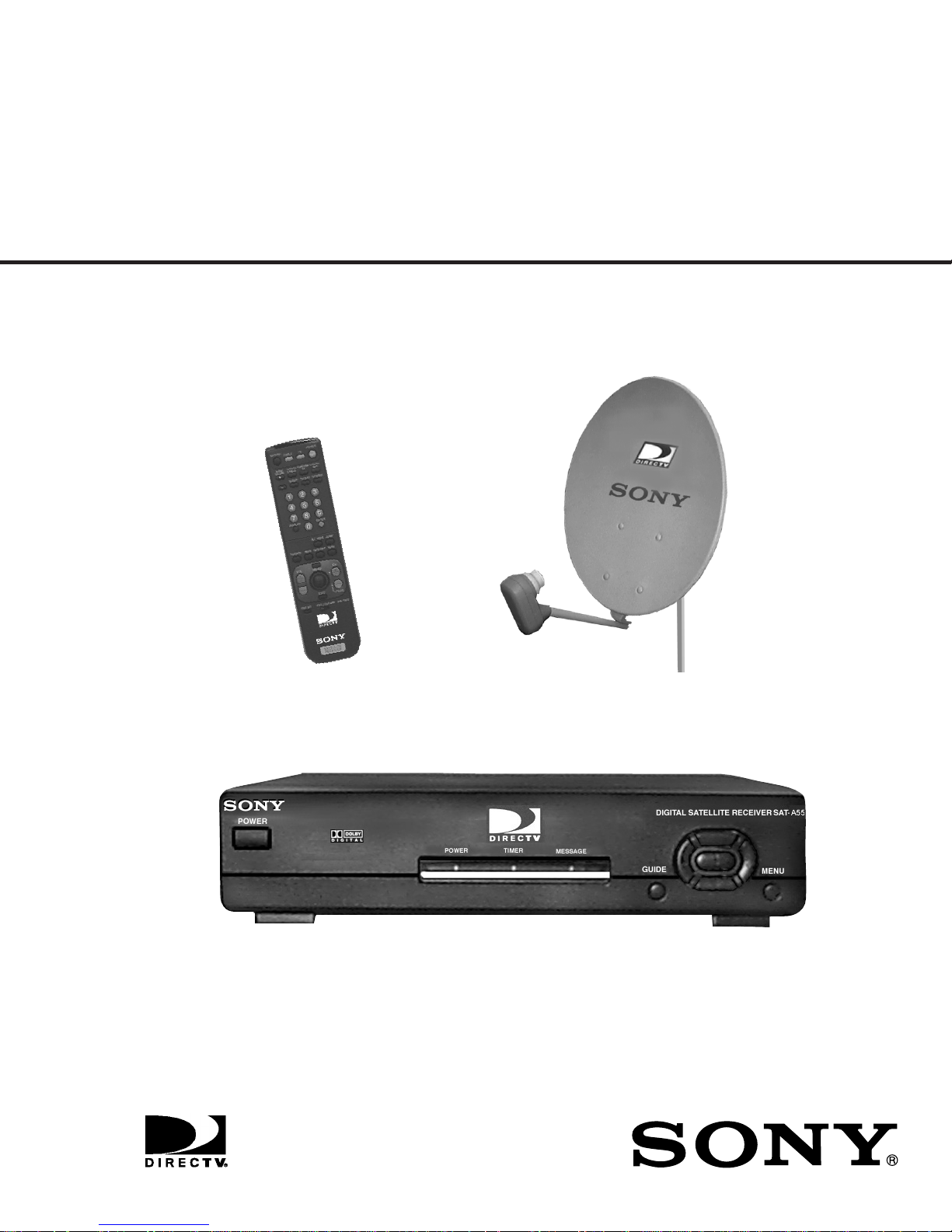
SERVICE MANUAL
RM-Y802
U.S. Model
SAN-18D3
DIGITAL SATELLITE RECEIVER/SATELLITE ANTENNA
SAT-A55
SAT-A55/B55
FOR DIGITAL SATELLITE RECEIVER:
SPECIFICATIONS
Input Jacks
Output Jacks
Input Frequency
Power Requirements
Power Consumption
Dimensions (w/h/d)
Weight
UHF/VHF 75 ohm F-type
Satellite Antenna 75 ohm F-type
RF Remote Antenna (SAT-A55 only)
AC Power (120V, 60 Hz)
S-VIDEO OUT 4-pin mini DIN
VIDEO (RCA jacks) (2)
AUDIO R/L (RCA jacks) (2)
VHF (SAT)/UHF 75 ohms F-Type
Low Speed Data, 9-pin D-Sub Female
Telephone Line (RJ11)
VCR control (1) VCR Controller (or monoaural cable for Sony SmartFile VCRs)
Optical output (1) (SAT-A55 only)
950 - 1450 Mhz / 950-2150 Mhz
120V AC, 60 Hz
20 W max.
5/8
x 9 inches
11 x 2
280 x 66.5 x 228.5 mm
SAT-A55 SAT-B55
Set: 6.0 lb (2.7 kg) Set: 5.4 lb (2.5 kg)
Unit: 3.6 lb (1.6 kg) Unit: 3.4 lb (1.5 kg)
Supplied Accessories
Remote Commander RM-Y802 (SAT-A55)
Remote Commander RM-Y139 (SAT-B55)
Size AA Batteries (2)
Access Card (1)
Audio/Video Cable (1)
S-VIDEO Cable (1) (SAT-A55 only)
Coaxial RF Cable (1)
RF Remote Antenna (1) (SAT-A55 only)
VCR Controller (1)
Telephone Cable (1)
AC Power Cord (1)
Optional Sony-brand DSS Accessories
Local TV Antenna ANJ-AA1
Installation Kit ANJ-DS2
Amplifier EAC-DA1
Diplexer EAC-DD1
Voltage Switch ECA-DV2
RF Universal Remote Commander
Remote Control RM-Y802
Design and specifications subject to change without notice.
— 2 —
FOR SATELLITE ANTENNAS:
SAT-A55/B55
Input Frequency
Output Frequency
Output Connector
Power Consumption
Supply Voltage
Dimensions (w/h/d)
Weight
12.2 - 12.7 GHz
950 - 1450 MHz
F-Type Female
3.0 W max.
DC + 10.5 - 14.0 V for RHCP
DC + 15.5 - 21.0 V for LHCP
5/8
18
x 31 x 18
473 x 787 x 643 mm
8 lbs 6 oz (3.8 kg)
5/16
inches
SAFETY CHECK-OUT
1. Check the area of your repair for unsoldered or poorlysoldered connections. Check the entire board surface for
solder splashes and bridges.
2. Check the interboard wiring to ensure that no wires are
“pinched” or contact high-wattage resistors.
3. Check that all control knobs, shields, covers, ground
straps, and mounting hardware have been replaced. Be
absolutely certain that you have replaced all the insulators.
4. Look for unauthorized replacement parts, particularly
transistors, that were installed during a previous repair.
Point them out to the customer and recommend their
replacement.
LEAKAGE TEST
SAFETY CHECK-OUT
Supplied
Accessories
Optional
Accessories
5. Look for parts which, though functioning, show obvious
signs of deterioration. Point them out to the customer and
recommend their replacement.
6. Check the line cords for cracks and abrasion. Recommend the replacement of any such line cord to the
customer.
7. Check the B+ and HV to see if they are specified
values. Make sure your instruments are accurate; be
suspicious of your HV meter if sets always have low HV.
8. Check the antenna terminals, metal trim, “metallized”
knobs, screws, and all other exposed metal parts for AC
leakage using one of the methods listed.
Weatherboot 2pcs
Signal Seeker 1pc
Snap-in Clip (dual type) 1pc
Bolt for Ground Terminal 1pc
Bolt for LNB Support Arm 2pcs
Installation Kit ANJ-DS2
Amplifier EAC-DA1
Diplexer EAC-DD1
Voltage Switch ECA-DV2
Multi-Room A/V
Distribution System MDR-D1
Coaxial Cable 25' SAK-C25
Coaxial Cable 75' SAK-C75
Flat Cable SAK-F1
The AC leakage from any exposed metal part to earth
ground and from all exposed metal parts to any exposed
metal part having a return to chassis, must not exceed 0.5
mA (500 microamperes). Leakage current can be measured by any one of three methods.
1. A commercial leakage tester, such as the Simpson 229
or RCA WT-540A. Follow the manufacturers’ instructions
to use these instruments.
2. A battery-operated AC milliammeter. The Data
Precision 245 digital multimeter is suitable for this job.
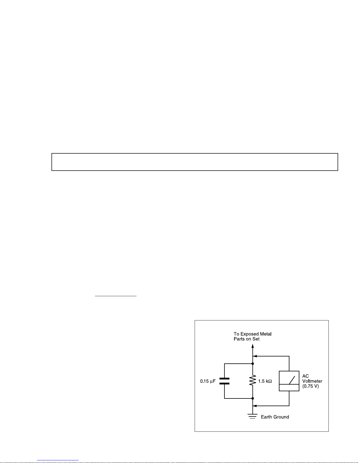
3. Measuring the voltage drop across a resistor by means
of a VOM or battery-operated AC voltmeter. The “limit”
indication is 0.75 V, so analog meters must have an
accurate low-voltage scale. The Simpson 250 and Sanwa
SH-63Trd are examples of passive VOMs that are
suitable. Nearly all battery operated digital multimeters
that have a 2 VAC range are suitable. (See Figure 1)
Figure 1. Using an AC voltmeter to check AC leakage.
— 3 —
SAT-A55/B55
TABLE OF CONENTS
Section Title Page
1. General --------------------------------------------------------------------------- 5
2. Disassembly
2-1. Upper Case Removal ---------------------------------------------------- 1 2
2-2. H Board Removal --------------------------------------------------------- 12
2-3. A, SC Board Removal --------------------------------------------------- 12
3. Service Test ---------------------------------------------------------------------- 12
4. Diagrams
4-1. Block Diagram -------------------------------------------------------------- 15
4-2. Circuit Boards Location --------------------------------------------------- 18
4-3. Schematic Diagrams and Printed Wiring Boards ----------------- 18
Schematic Diagrams of SC Board------------------------------ 19
Schematic Diagrams of HB Board------------------------------ 20
Schematic Diagram of A Board (1/4) -------------------------- 21
Schematic Diagram of A Board (2/4) -------------------------- 24
Schematic Diagram of A Board (3/4) -------------------------- 27
Schematic Diagram of A Board (4/4) -------------------------- 30
A Board PCB and Components Location --------------------- 3 3
4-4. Semiconductors ------------------------------------------------------------ 37
5. Exploded Views
5-1. SAT-A55/B55 Chassis ---------------------------------------------------- 38
5-2. SAN-18D3-------------------------------------------------------------------- 39
6. Electrical Parts List --------------------------------------------------------------- 40
SAFETY-RELATED COMPONENT WARNING !!
Components identified by shading and the critical mark
on the schematic diagrams, e xploded views, and in the
parts list are cr itical for safe operation. Replace these
with Sony parts whose part numbers appear as shown
in this manual or in supplements published by Sony.
Circuit adjustments that are critical for safe operation
are identified in this manual. Follow these procedures
whenever critical components are replaced or improper
operation is suspected.
!
— 4 —
— 5 —
SAT-A55/B55
The operating instructions mentioned here are partial abstracts from the
Operating Manual. The page numbers referenced here reflect those of the
Operating Instruction Manual.
SECTION 1
GENERAL
8
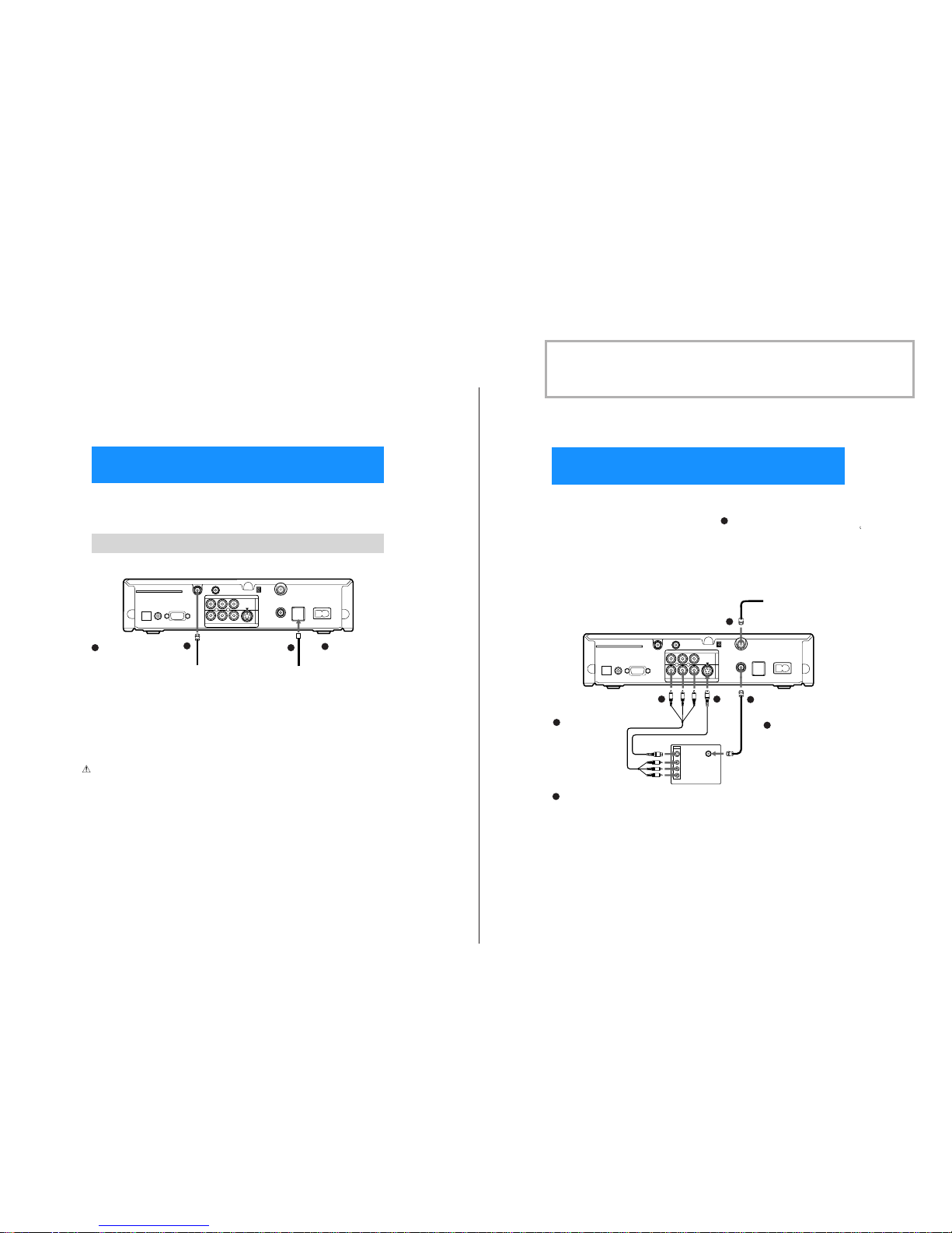
The SATELLITE IN jack sends power to, and receives satellite signals
from, the Satellite Dish Antenna. The telephone line connection
periodically sendsinformation about your receiver and Access Card to
your service provider.
Connections are shown using the SAT-A55 model. Any differences in connecting the SAT-B55
model are noted in the text.
ACCESS CARD
LOW SPEED DATA
VCR CONTROL
DIGITAL
OUT
(OPTICAL)
SATELLITE IN
RF REMOTE
R
L(MONO)
VIDEO OUT
AUDIO
VIDEO
S VIDEO
CH3
CH4
VHF/UHF IN
VHF(SAT)/UHF
OUT
TEL LINE
AC IN~
1
2
Digital Satellite Receiver
Connect the SATELLITE IN
jack to your Satellite Dish
Antenna using RG-6
coaxial cable.
RG-6 Coaxial Cable from
Satellite Dish Antenna
Telephone Cord
Connect the TEL LINE
jack to a telephone
line wall jack using
the supplied
telephone cord.
Note
• Your Satellite DishAntenna
Installation Instructions
provides detailedinstruc tions
on how toinstall RG-6 coaxial
cable fromyour Satellite Dish
Antenna.
CAUTION
Only connectyour authorized
Satellite DishAntenna to the
SATELLITE IN jackas described
in theInstallation Instructions.
Connecting any o ther equipment
to thisjack could resultin damage
to theequipme nt and/or receiver.
1
1
2
2
Step 2: Connecting the Satellite Dish Antenna
and Telephone Line
9
PLUS™ Digital Satellite Receiver
Connect your TVto the Digital Satellite Receiver as shownbelow. Refer
to your TV’s instruction manual for more information.
ACCESS CARD
LOW SPEED DATA
VCR CONTROL
DIGITAL
OUT
(OPTICAL)
SATELLITE IN
RF REMOTE
R
L(MONO)
VIDEO OUT
AUDIO
VIDEO
S VIDEO
CH3
CH4
VHF/UHF IN
VHF(SAT)/UHF
OUT
TEL LINE
AC IN~
1
2
VHF/UHF
VIDEO
L(MONO)
R
S VIDEO
IN
-AUDIO-
If you have a local TV antenna or cable
company service
Connectit to theVHF/UHF IN jackon yourDigital
Satellite Receiveru sing a coaxial cable or RF
adapter (not supplied).
You canview local stations using yourTV controls
.
Note
You mustuse the VHF(SAT)/UHF OUT jackto
connectto your TVor VCRwhen a localTV antenna
or cablecompany service is connected to the
VHF/UHFIN jack (see“2c” below and on page10)
.
If your TV has A/V input
jacks
Connect the VIDEOOUT
jacksonyourDigital
Satellite Receiverto the
A/Vinput jackson yourTV
using thesupplied A/V
cable.(Besuretomatchthe
colors ont hejacks with the
colored plugson the A/V
cable.)
If your TV has an S-Video
input
Use anS-Video cable
instead ofthe yellow video
connection.S-Video cableis
suppliedwith the SAT-A55
modeland is an optional
accessorywith theSAT-B55
model.
If yourTV has only one
audio input, connectit to
the L(MONO) jack onthe
receiver.
If your TV does not have
A/V jacks
Connect theVHF(SAT)/UHF
OUT jackto the VHF/UHF
input jackon your TV using
coaxial cable.
Setthe CH3/CH4switc hto the
channel thatdoes not carry offairbroadcastsinyourarea.
Note
With this connection,your
input sourcei s channel 3 or
channel 4 dependingon how
you setthe CH3/CH4 switch
on thereceiver.
Digital Satellite Receiver
Coaxial
Cable
A/V Cable
VIDEO
(yellow)
OR
S-Video
S-Video
Cable
TV
Coaxial
Cable
1
1
2a
2a
2b
2b
2c
2c
Step 3: Connecting Your TV
— 6 —
SAT-A55/B55
10
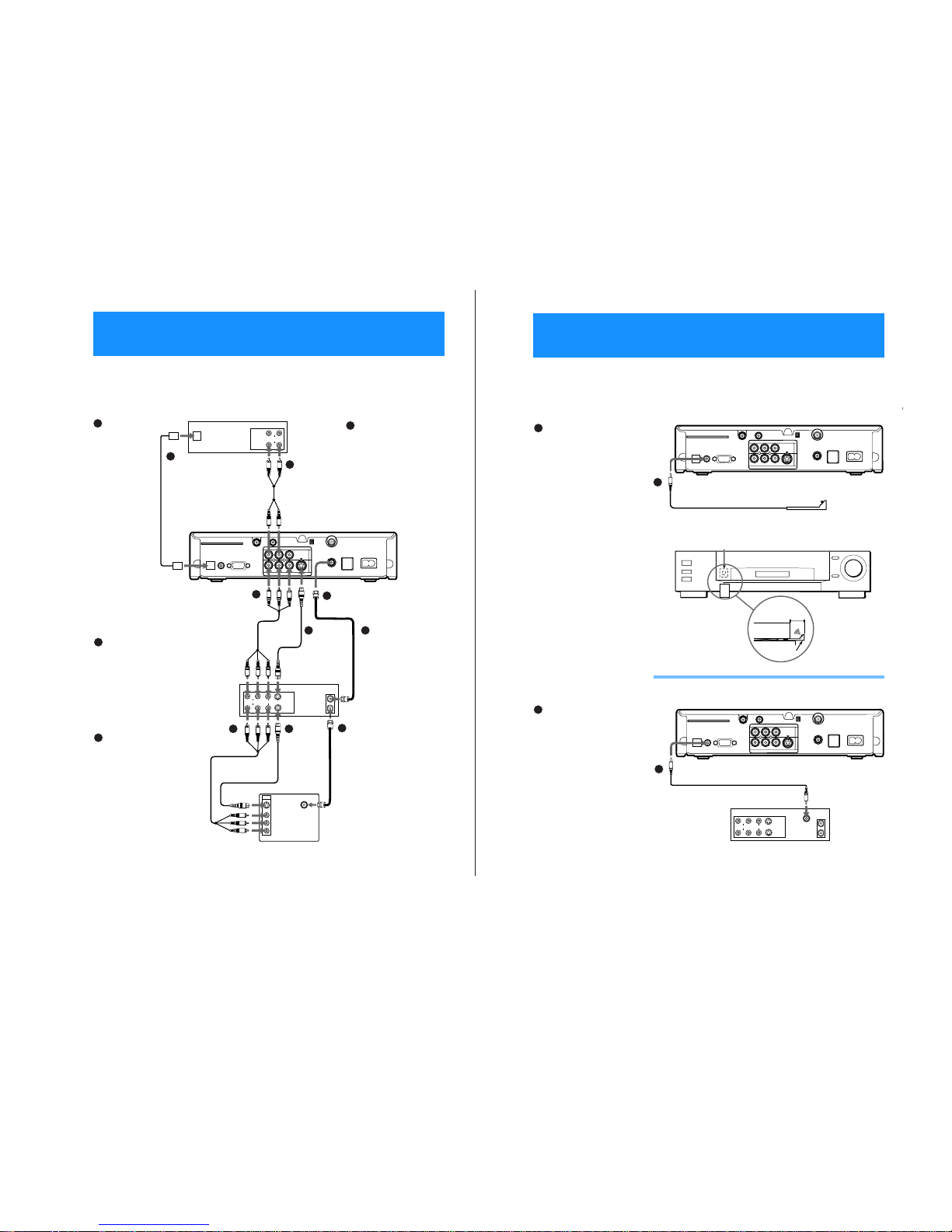
You can record programs by adding a VCR. You can also connect your
Digital Satellite Receiver to an audio system for enh anced sound
enjoyment.
VHF/UHF
VIDEO
L(MONO)
-AUDIOR
S VIDEO
IN
VIDEO
S VIDEO
AUDIO
LINE
IN
LINE
OUT
IN
OUT
ACCESS CARD
LOW SPEED DATA
VCR CONTROL
DIGITAL
OUT
(OPTICAL)
SATELLITE IN
RF REMOTE
R
L(MONO)
VIDEO OUT
AUDIO
VIDEO
S VIDEO
CH3
CH4
VHF/UHF IN
VHF(SAT)/UHF
OUT
TEL LINE
AC IN~
1
2
LINE
IN
LINE
OUT
AUDIO
OPTICAL
IN
If you have a
digital or Dolby
Digital audio
system (SAT-A55
only)
Connect the
DIGITAL OUT
(OPTICAL)ofthe
Digital Satellite
Receiver to the
optical digital
input ofyouraudio
system.
z
Tip
If youconnect your
Digital Satellite
Receivertoa Dolby
Digital receiver,set
the Dolby Digital
optionof the Audio
display to Auto
Select. See “Setting
Audio Options
(AUDIO)” on page
64 for more
information.
Audio Receiver
If you have a stereo
or Dolby
®
Pro Logic®
audio system
Connect the upp er
AUDIO Rand L(MONO)
jacks on theDigital
Satellite Receiver to the
audioinputsofyour
stereo amplifier.
If your TV and VCR have A/V
jacks
Connectthe VIDEOOUT jacks of
your Digital Satellite Receiverto
the A/V inputjacks of your VCR
using the supplied A/V cable.
Then, connect the A/V output
jacks of your VCRto the A/V
input jacks of your TV using an
A/Vcable.(Besuretomatchthe
colors on the jacks with the
colored plugs on theA/V cable.)
If your TV and VCR have
S-Video jacks
Use an S-Video cable insteadof
the yellow video connection.
S-Video cable is supplied with
the SAT-A55model and is an
optional accessory with the
SAT-B55 model.
z
Tip
To allow your Digital Sa tellite
Receiver to control the recording
functions of your VCR, see “Step
5: Connecting the VCR
Controller” on page 11.
Stereo
Cable
Optical Cable
(SAT-A55 only)
(optional Sony
accessoryPOC-15A)
Digital Satellite Receiver
If your TV and VCR do
not have A/V jacks
Connect the VHF(SAT)/
UHF OUT jackon the
Digital SatelliteReceiver to
the VHF/UHF input jack
on your VCR using coaxial
cable.
Then, connect the VHF/
UHFoutputjackonyour
VCR to the VHF/UHF
input jackon yourTV using
coaxial cable.
Set theCH3/CH4 switch to
the channel that does not
carry off-air broadcasts in
your area.
Note
With this connection,
your input source is
channel 3 or channel 4
depending on how you
set the CH3/CH4 switch
on your VCR.
A/V Cable
VIDEO
(yellow)
OR
S-Video
S-Video
Cable
Coaxial
Cable
TV
1a
1a
1b
1b
2a
2a
2b
2b
2a 2b
2c
2c
VCR
2c
A/V Cable
VIDEO
(yellow)
OR
S-Video
S-Video
Cable
Coaxial
Cable
Step 4: Adding a VCR and Audio System
11
PLUS™ Digital Satellite Receiver
Connect the VCR Controller to allow the Timer & Rec feature to
automatically operate your VCR.
See “Setting Up the VCR Control Feature” on page 26 for information
about setting up the Digital Satellite Receiver to work with your VCR.
ACCESS CARD
LOW SPEED DATA
VCR CONTROL
DIGITAL
OUT
(OPTICAL)
SATELLITE IN
RF REMOTE
R
L(MONO)
VIDEO OUT
AUDIO
VIDEO
S VIDEO
CH3
CH4
VHF/UHF IN
VHF(SAT)/UHF
OUT
TEL LINE
AC IN~
1
2
1
/
2
"
to 1
"
ACCESS CARD
LOW SPEED DATA
VCR CONTROL
DIGITAL
OUT
(OPTICAL)
SATELLITE IN
RF REMOTE
R
L(MONO)
VIDEO OUT
AUDIO
VIDEO
S VIDEO
CH3
CH4
VHF/UHF IN
VHF(SAT)/UHF
OUT
TEL LINE
AC IN~
1
2
VIDEO
S VIDEO
AUDIO
LINE
IN
LINE
OUT
IN
OUT
CPD IN
To allow the Digital
Satellite Receiver to
control your VCR
Connectthe VCRController
to the VCR CONTROLjack
on the receiver.
If you are using a Sony
SmartFile VCR to take
advantage of the Program Data
Download feature
Use this connection instead of the
VCR Controller connection.For
information about setting up t he
VCR Control feature,see page 26.
FordetailsabouttheProgramData
Download feature, referto your
SmartFile VCROperating
Instructions.
Digital Satellite Receiver
VCR Controller
Cable
VCR Controller
IR Sensor VCR (front view)
VCR (side view)
VCR
Controller
Connecting a Sony SmartFile™ VCR
Digital Satellite Receiver
Monaural Cable (supplied with
SmartFile VCR)
Sony SmartFile VCR
In front of the VCR
Place theVCR Controller underand in
front of the VCR.
The VCR Controller must extend just
in front of the infrared sensor of the
VCR.
z
Tip
If the infrared sensor isno t marked
on yourVCR, shine a flashlightinto
the front panel of the VCR tolocate
the sensor.
1b
1b
1a
1a
Step 5: Connecting the VCR Controller
— 7 —
SAT-A55/B55
12
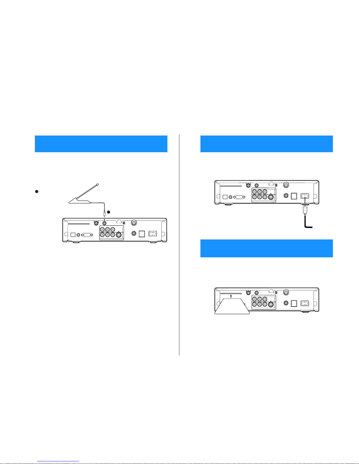
With the SAT-A55 model you can connect the RF Antenna and operate
the Digital Satellite Receiver when installed in a cabinet or from another
room in your house using the rem ote control. See page 32 for information
about how to set up the Digital Satellite Receiver to use the R F feat ure.
ACCESS CARD
LOW SPEED DATA
VCR CONTROL
DIGITAL
OUT
(OPTICAL)
SATELLITE IN
RF REMOTE
R
L(MONO)
VIDEO OUT
AUDIO
VIDEO
S VIDEO
CH3
CH4
VHF/UHF IN
VHF(SAT)/UHF
OUT
TEL LINE
AC IN~
1
2
If you want to use the RF
feature
Connect the RFAntenna to
theRFREMOTEjackofthe
Digital Satellite Receiver.
Then,placetheRFAntenna
in a convenient location.
RF Antenna
Digital Satellite Receiver
Notes
• Do not place the RF Antenna
directly on top of the Digital
Satellite Receiver or any other
metal object. For best results,
placetheRF Antenna in avisible
location.
• The operatingran ge of the
remote control is about 100 feet
when using the RF feature. This
may decrease due to ambient
reception conditions, weak
batteries, etc.
1
1
Step 6: Connecting the RF Antenna
(SAT-A55 only)
13
After all other connections are complete, connect the AC Power Cord to
the Digital Satellite Receiver. Then connect the AC Power Cord to a
power outlet.
After you insert the Access Card and your Satellite Dish Antenna is
installed, you are ready to begin enjoying digital satellite programming.
Call DIRECTV at 1-800-DIRECTV (347-3288) to begin service.
ACCESS CARD
LOW SPEED DATA
VCR CONTROL
DIGITAL
OUT
(OPTICAL)
SATELLITE IN
RF REMOTE
R
L(MONO)
VIDEO OUT
AUDIO
VIDEO
S VIDEO
CH3
CH4
VHF/UHF IN
VHF(SAT)/UHF
OUT
TEL LINE
AC IN~
1
2
AC Power Cord
to power outlet
Digital Satellite Receiver
ACCESS CARD
LOW SPEED DATA
VCR CONTROL
DIGITAL
OUT
(OPTICAL)
SATELLITE IN
RF REMOTE
R
L(MONO)
VIDEO OUT
AUDIO
VIDEO
S VIDEO
CH3
CH4
VHF/UHF IN
VHF(SAT)/UHF
OUT
TEL LINE
AC IN~
1
2
Digital Satellite Receiver
Access Card
Step 7: Connecting the AC Power Cord
Step 8: Inserting the Access Card
— 8 —
SAT-A55/B55
14
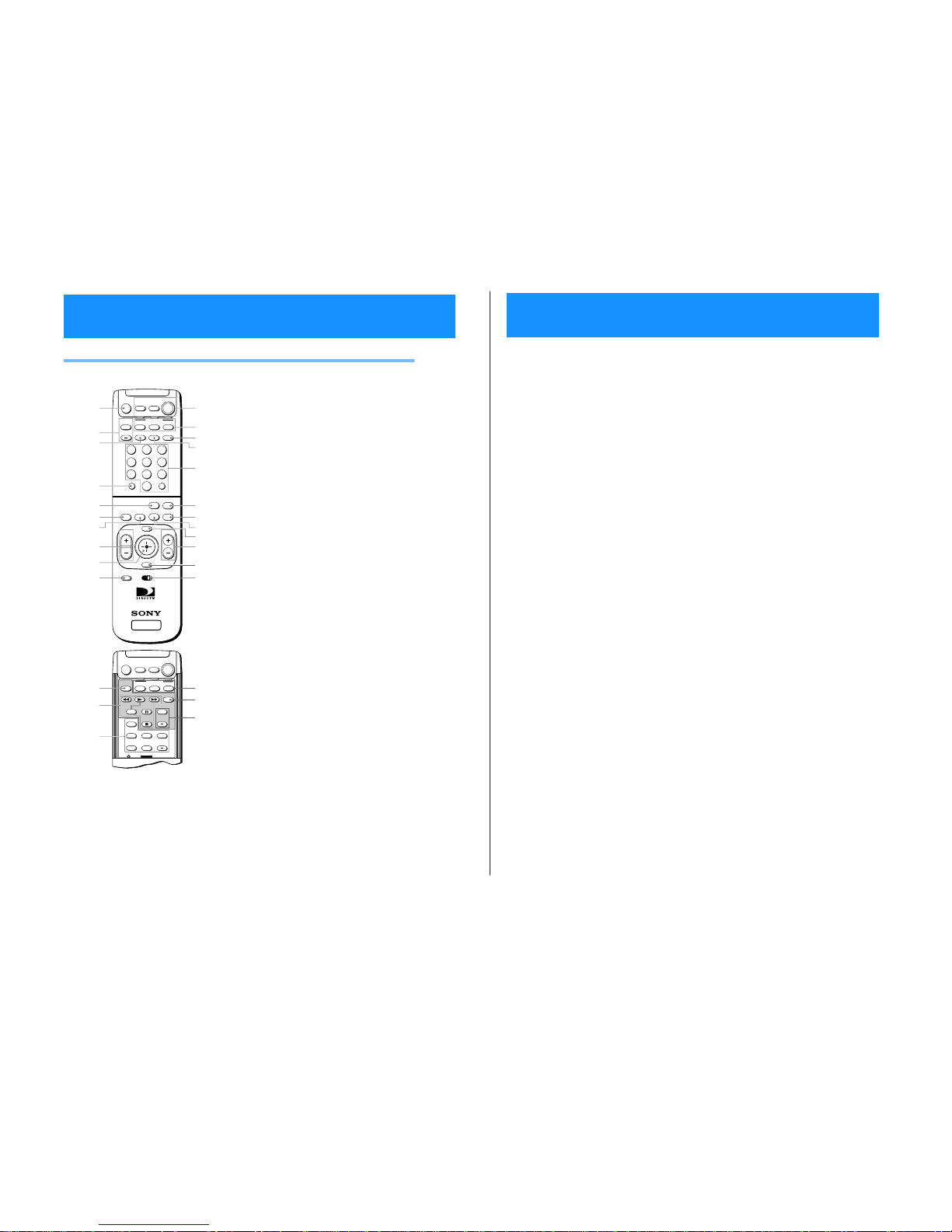
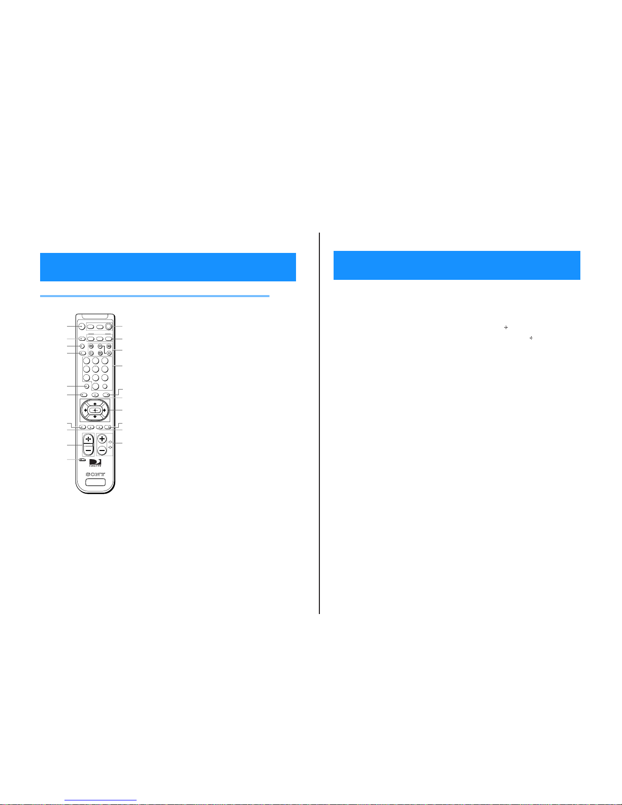
RM-Y802 Remote Control (SAT-A55 model)
Note
You may need to set up the remote control to operate your
other audio/video equipment. See “Setting Up the Remote
Control” on page 65 fordetails.
1 MUTING button
Mutes the volume. Press again torestore the
volume. To operate your TV, you must first set
up the remote control (see page 65).
2 AUDIO VOLUME buttons
Adjust the volume of your audio receiver. To
operateyouraudio receiver, you must firstsetup
the remote control (see page 65).
3 SLEEP button
Sets the TV to turn off automatically after a
certain amount of time (if your TV has the Sleep
feature). To operate your TV, you must first set
up the remote control (see page 65).
4 DISPLAY button
Opens the program information display for the
current program.
5 ALT AUDIO button
Switches among the available audio broadcasts.
6 FAVORITE button
Opens the Favorite Stations guide.
7 INDEX button
Opens the Station Index.
8 VOL buttons
Adjust the volume. To operate your TV, you
must first set up the remote control (see page 65).
9 Joystick
Moving the joystick up, down, left, and right
moves the highlight in on-screen displays. Press
the joystick to select the highlighted item.
q; CODE SET button
Lets you program the remote control to operate
your TV and other audio/video equipment (see
page 65).
SLEEP
TV/SAT
TV/VIDEO
SATELLITE
RECEIVER
ALT AUDIO
JUMP
GUIDE
INDEXFAVORITE
VOL
RM-Y802
VTR3 2 DVD AMP
MENU
EXIT
CH
CATEGORY
CODE SET
+
2
8
3
4
5
6
9
FUNCTION
SAT
CABLE
AUDIO
VOLUME
ENTERDISPLAY
1
7
TV
0
MUTING
CABLE TV
POWER
1
2
3
4
5
6
8
9
0
7
qs
qd
qg
qh
qj
ql
w;
ws
qk
qf
qa
SAT
wa
-
-
POSITION
CH
SWAP PIP
+
TV
SAT
CABLETV/VTR
FUNCTION
-
-
AUDIO OFF
CH
+
POWER
MUTING
CABLE TV
POWER
wh
wj
wk
wd
wg
wf
SAT
Viewing Pictures From Your DIRECTV PLUS™ Digital Satellite Receiver
Using Your Remote Control
1
5
qa POWER buttons
Turn on and off the Digital Satellite Receiver and
other audio/video equipment. To operate your
TV and other audio/video equipment, you must
first set up the remote control (see page 65).
qs FUNCTION buttons
Select the equipment (CABLE, TV or SAT) that
you want to operate. The indicators light up to
show which device theremote control is
operating. To operate your TV or cable box, you
must first set up the remote control (see page 65).
qd TV/VIDEO button
Switches between the various inputs of your TV.
To operate your TV, youmust first set up the
remote control (see page 65).
qf TV/SAT button
Switches the output of your Digital Satellite
Receiver between regular TV and satellite
broadcasts. To receive regular TV broadcasts,
youmusthavealocalTVantennaorcable
company connection (see page 9).
qg 0–9 and ENTER buttons
Change channels directly, and enter numerical
values in on-screen displays.
qh JUMP button
Changes channels to the previously tuned
channel.
qj GUIDE button
Opens the Program Guide.
qk CATEGORY button
Opens the Category Guide.
ql MENU button
Opens the Main Menu.
w; CH buttons
Change channels. When a program guide is
open, pressingtheCH buttons pages throughthe
guide.
wa EXIT button
Closes all on-screen displays including program
guides and menus.
ws VTR3/2/DVD/AMP switch
Sets the remote to operate other devices in your
A/V system. To operate these other devices, you
must first set up the remote control (see page 65).
wd TV/VTR button
Switches between the TV and VTR (VCR) inputs
of your TV. To operateyour TV, you must first
set up the remote control (see page 65).
wf VCR Control buttons
Operate VCR features such as play, record,
pause, stop, andfastwind.Tooperate your VCR,
you mustfirstsetup the remote control (see page
65).
wg PIP control buttons
Operate the Picture-in-picture features of your
TV (if your TV has PIP).TooperateyourTV,you
must first set up the remote control (see page 65).
wh FUNCTION buttons
Select the equipment (CABLE, TV or SAT) that
you want to operate. The indicators light up to
show which device theremote control is
operating. To operate your TV or cable box, you
must first set up the remote control (see page 65).
wj POWER button
Turns on or off the equipment selected with the
VTR3/2/DVD/AMP switch.
wk CH +/– buttons
Change channels in numerical order on the
equipment selected with the VTR3/2/DVD/
AMP switch.
— 9 —
SAT-A55/B55
16
RM-Y139 Remote Control (SAT-B55 model)
Note
You may need to set up the remote control to operate your
other audio/video equipment. See “Setting Up the Remote
Control” on page 65 fordetails.
1 MUTING button
Mutes the volume. Press again torestore the
volume. To operate your TV, you must first set
up the remote control (see page 65).
2 TV/VIDEO button
Switches between the inputs ofyour TV. To
operate yourTV,you must first set up the remote
control (see page 65).
3 TV/VTR button
Switches between the inputs ofyour VCR. To
operateyourVCR,youmustfirstsetupthe
remote control (see page 65).
4 TV/SAT button
Switches the output of your Digital Satellite
Receiver between regular TV and satellite
broadcasts. To receive regular TV broadcasts,
you must have a local TV antenna or cable
company connection (see page 9).
5 DISPLAY button
Opens the program information display for the
current program.
6 INDEX button
Opens the Station Index.
7 JUMP button
Changes channels to the previously tuned
channel.
8 EXIT button
Closes all on-screen displays including program
guides and menus.
CH
VOL
GUIDE
CATEGORYINDEX
ENTER
TV/VTR
FUNCTION
SAT
TVTV/VIDEO
DISPLAY
TV
POWER
PAGE
SAT
MUTING
VTR
VTR
TV/SAT
FAVORITEMENUJUMP EXIT
CODE SET
RM-Y139
SATELLITE
RECEIVER
0
1283
456
79
1
2
3
4
5
6
8
9
0
7
qs
qd
qf
qj
w;
qk
qa
qg
qh
ql
Using Your Remote Control (continued)
17
9 VOL buttons
Adjust the volume. To operate your TV, you
must first set up the remote control (see page 65).
q; CODE SET button
Lets you program the remote control to operate
your TV and other audio/video equipment (see
page 65).
qa POWER buttons
Turn on and off the Digital Satellite Receiver, TV
and VTR (VCR). To operateyour TV or VTR
(VCR), you must first setup the remote control
(see page 65).
qs FUNCTION buttons
Select the equipment (SAT, TV, VTR) that you
want to operate. The indicators light up to show
which device the remote control is operating. To
operate your T V or VTR (VCR), youmust first set
up the remote control (see page 65).
qd VCR Control buttons
Operate VCR features such as play, record,
pause, stop, and fast wind. To operate yourVTR
(VCR), you must first setup the remote control
(see page 65).
qf 0–9 and ENTER buttons
Change channels directly and enter numerical
values in on-screen displays.
qg GUIDE button
Opens the Program Guide.
qh CATEGORY button
Opens the Category Guide.
qj Arrow and buttons
The arrow buttons move the highlight in
on-screen displays. The button selects the
highlighted item.
qk FAVORITE button
Opens the Favorite Stations guide.
ql MENU button
Opens the Main Menu.
w; CH/PAGE buttons
Change channels. When a program guide is
open, these buttons page through the guide.

SAT-A55/B55
3
7
continued
not broadcast all of the languages in the Default Audio pop-up
(see page 64).
lost or forgotten your passcode, contact your service provider.
the Locks & Limits (see page 58).
Blocked are set as you want them (see pages 53–56). Then, make
sure that the system is locked (see page 57).
Favorite Stations guide (see page 41).
highlight appears in the Media Window display, you must press
the button to complete your selection (see page 37).
Contact your service provider for details.
information (station, start time, etc.) about programs that you
telephone line (see page 8).
youmustcontactyourserviceprovidertoordertheprogram.
provider.
• Make sure the system is not locked (see page 58).
• Use the Program Guide to access the station (see page 37).
• If the message “Purchase information not available” appears,
• YourAccess Card may be full. If so, contact your service
•Itmaybetoolatetoordertheprogramyouwant.Ifso,checkfor
have ordered.
other show times (see page 45).
• See “Checking Pay Per View Purchases” on page 59 to get
• Highlight and select the program. Although the program you
• Check the default language setting. The program provider may
• Some programs may not offer audio tracks.
Language of audio track is incorrect or audio
Problem What you can do
You cannot order a pay per view program • Make sure your Digital Satellite Receiver is connected to a
®
You cannot find the station of the pay per
view program that you ordered
You cannot cancel a pay per view order • Youcannot cancel pay per view orders that you have watched.
The program highlighted in the Program
Guide does not appear
You cannot see any Favorite Stations • Set up your personal Favorite Titles before you try to use the
You cannot access the Locks & Limits screens • The system must be unlocked before you can make changes to
Locks & Limits feature not working properly • Make sure that the Spending, Rating, Pay Per View, and Stations
track is not available
You cannot unlock the system • Make sure that you entered the passcode correctly.If you have
Yourservice provider can tell you to which stations you
subscribe.
skipped (see pages 50–51).
coming from the satellite to your Satellite Dish Antenna. To limit
any negative effects during degraded conditions, make sure that
your professionalinstallerhasaimedyour Satellite Dish Antenna
copy protection at the discretion of the copyright owner. You
may want to connect the Digital Satellite Receiver directly to
your TV.
(see pages 7–13).
sourceto which you connected your Digital Satellite Receiver, for
example, channel 3 or 4, Video 1 or 2 (see pages 9–10).
Satellite Dish Antenna.
Digital Satellite Receiver is more than 100 feet, you must use the
Sony Amplifier EAC-DA1.
Satellite Receiver.
Digital SatelliteReceiver.This could improvepicturequalityonly
if you are using the UHF/VHF IN jack of the Digital Satellite
example), call your service provider to have your programming
activated.
• Some pay per view programs may be protected by Macrovision
• Check the connections to your TV and other equipment
• Make sure that your TV and other equipment are set to the input
• Check the Satellite Dish Antenna’s signal strength (see page 23).
• Make sure the RG-6 coaxial cable is properly connected to the
•IfthecabledistancebetweentheSatelliteDishAntennaandthe
• Make sure your Access Card is inserted correctly (see page 13).
• Move any antenna cables that may be directly above your Digital
Receiver to connecta local TV antenna or cable company service.
• Change the setting of the CH3/CH4 switch on the back of the
so that you are receiving a high signal strengthlevel (see page 23,
• Heavy rain or snow may degrade the strength of the signal
wait a few minutes, then plug in the AC Power Cord again.
or refer to your Satellite Dish Antenna Installation Instructions).
• If the AC Power Cord is plugged in, unplug the AC P ower Cord,
• Make sure the station you are trying to access is not set to be
you select a channel (see page 20).
• Make sure the system is not locked (see page 58).
• Use the Program Guide to access the station (see page 37).
• Press the SAT FUNCTION button on the remote control before
Troubleshooting
Problem What you can do
Poor picture quality or no picture • If you are receiving only a few stations, (only 2 or 3 channels for
— 10 —
You cannot access a program • Make sure you subscribe to the station you are trying to access.
Poor picture quality or no picture when
it rains or snows
You cannot turn on the unit • Make sure that the AC Power Cord is plugged in (see page 13).
72

— 11 —
SAT-A55/B55
74
You cannot record programs with your VCR • Make sure that your VCR is connected correctly (see page 10).
•IfyouwanttousetheVCRControlfeature,makesurethatthe
VCR Controller is connected correctly (seepage11).Also make
sure that you have selected the correct VCR Manufacturer Code
(see page 27).
• If you are using the VCR Control feature to record a future
program, make sure that your VCR is turned off beforethe
program begins. The VCR Controlfeaturewill turn on the VCR
and start recording.
• Make sure that the program you are trying to recorddoesn't
conflict with any Locks & Limits you have set.
• If you are trying to record a pay perviewprogram, you must first
order the program(see page 45).
• Some pay perview programs may be protected by Macrovision
copy protection at the discretion of the copyright owner.If so, it
may not be possible to record these programs.
Access Card problems • Make sure your Access Card is inserted correctly (see page 13).
• Contact your service provider with any other Access Card
problems.
Remote control does not work • Make sure that the batteriesare inserted correctly and that the
batteries are not weak (see page7).
• Remove and then reinsert the batteries without pressing any
buttons on the remote control.
• To operate your TV or other equipment,make sure that the
remote control is set up to operate that equipment (see page 65).
If thebatteriesare removed or become weak,youmay need to set
up the remote control to operate other equipment again.
• Pres s the FUNCTION button on the remote control of the
equipment you want to operate (SAT, TV,VTR, and/or CABLE).
These buttons will flash to show which equipment the remote
control is set to operate.
• SAT-A55 model only: If there is a problem when using the RF
function, check thattheRF Antenna is connected correctly
(see page 12).
• SAT-A55 model only: Makesurethatthe remote control and the
Digital Satellite Receiver are both using the same security code
(see page 33–34).
Audio noise • SAT-A55modelonly: If you connect the DIGITAL OUT jack to
equipment that is not Dolby Digital compatible, settheDolby
Digital option to “off” (see page 64). Not all optical jacks on
audio systems are Dolby Digital compatible.
“Frozen” picture or display • Press both the GUIDEand ARROW DOWN buttons at the same
time on the front panel of the Digital Satellite Receiver to reset
the receiver.
Problem What you can do
If you are unable to resolve problemswithyoursystem,see“CustomerSupport” inside the front cover.
Troubleshooting
(continued)
 Loading...