

Sony HDC2500, HDC2550, HDC2400, DigitalHDVS HDC2570, HDC1700 Operation Manual

HD COLOR CAMERA
HDC2500
HDC2400
HDC2550
OPERATION MANUAL [English]
1st Edition (Revised 2)
Before operating the unit, please read this manual thoroughly
and retain it for future reference.
You are cautioned that any changes or modifications not
expressly approved in this manual could void your authority to
operate this equipment.
WARNING
To reduce the risk of fire or electric shock,
do not expose this apparatus to rain or
moisture.
To avoid electrical shock, do not open the
cabinet. Refer servicing to qualified
personnel only.
For laser-related devices
(HDC2500/2400/Option HKC-FB20 installed)
This HD Color Camera is classified as a CLASS 1 LASER
PRODUCT.
Diese HD-Farbkamera ist als LASERPRODUKT DER
KLASSE 1 eingestuft.
Tämä HD-värikamera on luokiteltu 1. LUOKAN
LASERTUOTTEEKSI.
Den här HD-färgkameran klassificeras som en
LASERPRODUKT AV KLASS 1.
CAUTION
Use of controls or adjustments or performance of
procedures other than those specified herein may result in
hazardous radiation exposure.
CAUTION
The use of optical instruments with this product will
increase eye hazard.
All interface cables used to connect peripherals must be
shielded in order to comply with the limits for a digital device
pursuant to Subpart B of Part 15 of FCC Rules.
This device complies with Part 15 of the FCC Rules. Operation
is subject to the following two conditions: (1) this device may
not cause harmful interference, and (2) this device must
accept any interference received, including interference that
may cause undesired operation.
For the customers in Canada
This Class A digital apparatus complies with Canadian ICES-
003.
For the customers in Europe
This product with the CE marking complies with the EMC
Directive issued by the Commission of the European
Community.
Compliance with this directive implies conformity to the
following European standards:
• EN55103-1: Electromagnetic Interference(Emission)
• EN55103-2: Electromagnetic Susceptibility(Immunity)
This product is intended for use in the following
Electromagnetic Environments: E1 (residential), E2
(commercial and light industrial), E3 (urban outdoors), E4
(controlled EMC environment, ex. TV studio).
The manufacturer of this product is Sony Corporation, 1-7-1
Konan, Minato-ku, Tokyo, 108-0075 Japan.
The Authorized Representative for EMC and product safety is
Sony Deutschland GmbH, Hedelfinger Strasse 61, 70327
Stuttgart, Germany. For any service or guarantee matters
please refer to the addresses given in separate service or
guarantee documents.
For the customers in Taiwan only
For the customers in the U.S.A.
This equipment has been tested and found to comply with the
limits for a Class A digital device, pursuant to Part 15 of the
FCC Rules. These limits are designed to provide reasonable
protection against harmful interference when the equipment is
operated in a commercial environment. This equipment
generates, uses, and can radiate radio frequency energy and,
if not installed and used in accordance with the instruction
manual, may cause harmful interference to radio
communications. Operation of this equipment in a residential
area is likely to cause harmful interference in which case the
user will be required to correct the interference at his own
expense.
2
AVERTISSEMENT
Afin de réduire les risques d’incendie ou
d’électrocution, ne pas exposer cet
appareil à la pluie ou à l’humidité.
Afin d’écarter tout risque d’électrocution,
garder le coffret fermé. Ne confier
l’entretien de l’appareil qu’à un personnel
qualifié.

Pour les clients au Canada
Cet appareil numérique de la classe A est conforme à la
norme NMB-003 du Canada.
Pour les clients en Europe
Ce produit portant la marque CE est conforme à la Directive
sur la compatibilité électromagnétique (EMC) émise par la
Commission de la Communauté européenne.
La conformité à cette directive implique la conformité aux
normes européennes suivantes :
• EN55103-1 : Interférences électromagnétiques (émission)
• EN55103-2 : Sensibilité électromagnétique (immunité)
Ce produit est prévu pour être utilisé dans les environnements
électromagnétiques suivants : E1 (résidentiel), E2
(commercial et industrie légère), E3 (urbain extérieur) et E4
(environnement EMC contrôlé, ex. studio de télévision).
Le fabricant de ce produit est Sony Corporation, 1-7-1 Konan,
Minato-ku, Tokyo, 108-0075 Japon.
Le représentant autorisé pour EMC et la sécurité des produits
est Sony Deutschland GmbH, Hedelfinger Strasse 61, 70327
Stuttgart, Allemagne. Pour toute question concernant le
service ou lagarantie, veuillez consulter les adresses
indiquées dans les documents de service ou de garantie
séparés.
an die in den separaten Kundendienst- oder
Garantiedokumenten aufgeführten Anschriften.
WARNUNG
Um die Gefahr von Bränden oder
elektrischen Schlägen zu verringern, darf
dieses Gerät nicht Regen oder Feuchtigkeit
ausgesetzt werden.
Um einen elektrischen Schlag zu
vermeiden, darf das Gehäuse nicht
geöffnet werden. Überlassen Sie
Wartungsarbeiten stets nur qualifiziertem
Fachpersonal.
Für Kunden in Europa
Dieses Produkt besitzt die CE-Kennzeichnung und erfüllt die
EMV-Richtlinie der EG-Kommission.
Angewandte Normen:
• EN55103-1: Elektromagnetische Verträglichkeit
(Störaussendung)
• EN55103-2: Elektromagnetische Verträglichkeit
(Störfestigkeit)
Für die folgenden elektromagnetischen Umgebungen: E1
(Wohnbereich), E2 (kommerzieller und in beschränktem
Maße industrieller Bereich), E3 (Stadtbereich im Freien) und
E4 (kontrollierter EMV-Bereich, z.B. Fernsehstudio).
Der Hersteller dieses Produkts ist Sony Corporation, 1-7-1
Konan, Minato-ku, Tokyo, 108-0075 Japan.
Der autorisierte Repräsentant für EMV und Produktsicherheit
ist Sony Deutschland GmbH, Hedelfinger Strasse 61, 70327
Stuttgart, Deutschland. Bei jeglichen Angelegenheiten in
Bezug auf Kundendienst oder Garantie wenden Sie sich bitte
3

Table of Contents
Overview..................................................................... 5
Features ...........................................................................5
System Configuration.......................................................9
Locations and Functions of Parts.......................... 12
Accessory Attachments..................................................12
Controls and Connectors ...............................................12
Preparations............................................................. 19
Attaching a Lens ............................................................19
Adjusting the Flange Focal Length.................................19
Attaching a Viewfinder ...................................................19
Attaching the Cable Clamp Belt (Supplied)....................21
Adjusting the Shoulder Pad Position..............................22
Mounting the Camera to a Tripod ..................................22
Adjustments and Settings for Shooting................ 24
Adjusting the Black Balance and White Balance ...........24
Setting the Electronic Shutter.........................................26
Setting the Focus Assist Functions................................27
Setting the Camera Outputs ................................... 29
Viewfinder Screen Status Display.......................... 31
Menu Operations ..................................................... 32
Starting Menu Operations ..............................................32
Selecting Pages .............................................................33
Setting the Menu Items ..................................................34
Editing the USER Menu .................................................35
Menu List.................................................................. 39
Menu Tree......................................................................39
OPERATION Menu ........................................................43
PAINT Menu...................................................................49
MAINTENANCE Menu ...................................................53
FILE Menu......................................................................57
DIAGNOSIS Menu .........................................................59
Appendix .................................................................. 61
Precautions ....................................................................61
Error Messages..............................................................61
Using a USB Drive ................................................... 62
Specifications .......................................................... 63
HDC2500 .......................................................................63
HDC2400 .......................................................................64
HDC2550 .......................................................................65
Optional Accessories/Related Equipment......................66
Dimensions ....................................................................67
Notice Concerning Software Governed by the GNU
GPL/LGPL................................................................. 68
Table of Contents
4

Overview
The HDC2500, HDC2400 and HDC2550 are 2/3-type highdefinition portable video cameras equipped with CCD for
2,200,000 pixels.
The differences among the models are shown below:
HDC2500 HDC2400 HDC2550
CCD Progressive IT Progressive IT Progressive IT
Video format
coverage
Built-in filters Optical ND filers (clear, 1/4ND, 1/8ND,
* 2× slow motion format.
Features
1080/50i, 1080/59.94i, 1080/
23.98PsF, 1080/24PsF, 1080/25PsF,
1080/29.97PsF, 1080/50P, 1080/
59.94P, 720/59.94P, 720/50P, 1080/
100i*, 1080/119.88i*, 720/100P*, 720/
119.88P*
1/16ND, 1/64ND)
Optical CC filters (cross, 3200K,
4300K, 6300K, 8000K)
Electric filter (5600K)
1080/59.94i, 720/59.94P, 1080/50i,
720/50P
Optical ND filters (clear, 1/4ND, 1/
16ND, 1/64ND)
Optical cross filter
Electric filter (5600K)
1080/59.94i, 720/59.94P, 1080/50i,
720/50P
Optical ND filers (clear, 1/4ND, 1/8ND,
1/16ND, 1/64ND)
Optical CC filters (cross, 3200K,
4300K, 6300K, 8000K)
Electric filter (5600K)
High picture quality and high performance
HDC2400/2500/2550 features a 2/3-type wide progressive IT
CCD for 2,200,000 pixels and a signal processing LSI, both
newly developed to help achieve a high level of image quality
via improved S/N, high resolution, and low smear compared to
previous models. A 16-bit AD converter allows for optimal
picture quality and enhanced black reproduction.
Slow motion via 2× speed recording
1080/50i-59.94i and 720/50P-59.94P formats are supported,
as well as 1080/23.98PsF-24PsF-25PsF-29.97PsF and 1080/
50P-59.94P progressive formats, and 1080/100i-119.88i and
720/100P-119.88P slow-motion 2× speed recording formats.
For the models that do not support this function by default, use
optional accessories to use this function. For details, see
“Optional Accessories” (page 7).
Digital extender function
The central part of the viewfinder picture is digitally magnified
to twice its size.
The digital extender function prevents the decrease in
sensitivity (F-drop) that occurs when the lens extender
function is used.
Note
This function does not operate when a 2x slow motion format
is selected.
This function also reduces the resolution of images to onehalf.
Aberration correction function
This camera features ALAC 2.0 (Auto Lens Aberration
Compensation).
When an achromatic lens is used, this function reduces
chromatic aberration of magnification automatically.
For details on achromatic lenses, contact a Sony sales
representative or Sony service representative.
Standard 3G optical digital transmission unit
(HDC2500/2400)
3G optical digital transmission of signals between the camera
and camera control unit (CCU) is included, and allows the
following kinds of video signal transmission and system
configurations:
• 1080/50P-59.94P progressive video signal transmission
• Transmission of 2× speed recording signals such as 1080/
100i-119.88i for production of slow-motion video
• Transmission of HD prompter, HD TRUNK, and network
TRUNK signals that utilize empty bands during 1080/50i-
59.94i and 720/50P-59.94P operation
• Dual camera system for transmitting video signals from two
HDC2500/2400 cameras to two CCUs using just one optical
fiber/multi-cable
• Subcamera system for transmitting video signals from both
an HDC2500/2400 and another subcamera-such as the
HDC-P1-using just one optical fiber/multi-cable and
outputting their signals from one CCU
Triax transmission (HDC2550)
HDC2550 utilizes a triax transmission system and supports
1080/50i-59.94i and 720/50P-59.94P formats.
Overview
5

Various color-reproduction functions
Adaptive-matrix function
This function accurately controls calculation factors for
performing accurate color conversion when shooting. This
makes precise color conversion possible even when shooting
under conditions that would otherwise exceed the color
conversion range of traditional matrix functions, such as under
strong monochromatic blue light sources.
Multimatrix color correction
In addition the standard 6-axis matrix function, the camera has
a multimatrix function that permits you to adjust the hue and
chroma for color components in 16-axis directions
independently. This is quite useful in color matching among
multiple cameras.
Knee saturation
Change of hue and decrease in chroma that occur in
highlighted areas can be compensated.
This enables reproduction of natural skin tones under strong
lighting.
Low key saturation
Saturation in low-key zones can be compensated. Thus,
compensation for color reproduction in all zones is enabled in
combination with matrix color compensation and knee
saturation functions.
Selection of multiple gamma tables
Seven types of standard and 4 types of hyper gamma tables
are provided with this camera. The hyper gamma values
enable cinemalike image creations with wide dynamic range,
which are different from those achieved with conventional
video gamma.
User gamma
Gamma tables created with CvpFileEditor™ can be saved to
a “Memory Stick,” or registered to HDC2500/2400 from the
MSU-1000/1500 or RCP-1500 series.
Versatile detail control functions
Skin-tone detail function/Natural skin detail
function
Like HDC1500R/1400R/1550R, this function allows control
(emphasis or suppression) of the detail level for just a certain
hue or chroma area in the image, by creating a detail gate
signal from color components of your specified hue, such as
skin tones. The detail levels of three hues can be adjusted
independently at the same time.
HDC2500/2400/2550 features the natural skin detail function,
which allows for adjustment of the detail gate signal, allowing
even more vivid distinction of areas like skin that you want to
make smooth while selectively keeping areas like eyebrows
that don’t require smoothing.
Detail boost-frequency control
The boost frequency can be adjusted from 20 to 30 MHz. This
allows the thickness of the detail signal to be set appropriately
for the subject, thus enabling high-definition image
expression.
H/V ratio control
The ratio between horizontal and vertical detail can be
adjusted.
White/black limiter
The white and black details can be limited independently.
Focus assist functions
The VF detail function and focus assist indicator function
facilitate focusing.
VF detail
Various functions are provided for the VF detail signal, which
can be added only on images on the viewfinder screen in order
to facilitate focusing in various situations: Functions for
coloring the VF detail signal, flickering the VF detail signal by
adding modulation, thickening the VF detail signal, and
changing the VF detail level according to the zoom position.
Focus assist indicator
The focusing level indicator on the viewfinder screen provides
a guide for focusing. The best focus setting can be easily
determined by observing fluctuation of the level indicator as a
guide.
Numerous viewfinder functions
Wide variety of viewfinder display options
Along with items such as operation messages, a zebra
pattern, a safety-zone marker, and a center marker, camera
settings may also be displayed on the viewfinder screen.
Furthermore, there are other indicators arranged above and
below the viewfinder, such as a tally lamp, battery warning
indicator, and an indicator to tell you that one or more settings
are other than standard. This makes it simple to check the
status of the camera.
Menu-based setting operation function
Selections and settings for viewfinder display items, a safetyzone marker or center marker, screen size marker, etc. can be
made quickly and easily using setup menus displayed on the
viewfinder screen or an external monitor.
PinP function
The return video signal can be displayed on the viewfinder in
picture-in-picture mode.
Note
The PinP function cannot be used during stand-alone
operation, and cannot be used with the HD TRUNK FRAME
SYNCHRO function simultaneously.
Wide variety of input/output interfaces
(HDC2500/2400)
In addition to 3G/HD/SD-SDI output and HD/SD-SDI input,
HDC2500/2400 features a wide variety of input/output
interfaces, including the following:
Network TRUNK function (HDC2500/2400)
The network TRUNK function (LAN port) allows for data
transmission between the camera and CCU at speeds of up to
6
Overview

1 Gbps. This allows for a multitude of new system
configurations, such as connecting several IP transmission
cameras as subcameras.
possible. This enables the same total longitudinal size as a
standard studio-use camera, for operability equivalent to that
of a standard studio-use camera.
Note
The network TRUNK transfer rate differs depending on the
video format. Jumbo frames are not supported.
HD TRUNK function (HDC2500/2400)
The new HD TRUNK function uses 3G optical transmission
supports sending HD-SDI-equivalent digital data (not an HDSDI video signal) from the HDC2500/2400 to an HDCU2000/
2500.
Note
The HD TRUNK function can only be used when a single
format is selected and the network TRUNK function is set to
OFF.
HD prompter function (HDC2500/2400)
The new HD prompter function on HDC2500/2400 supports
sending HD-SDI-equivalent digital data (not an HD-SDI signal)
separate from the return video signal from an HDCU2000/
2500 to the HDC2500/2400.
Note
The HD prompter function can only be used when a single
format is selected and the network TRUNK function is set to
OFF.
Position-adjustable shoulder pad
The position of the shoulder pad can be adjusted for stable
shooting according to the build of the camera operator, the
type of lens in use, or the shooting style.
A low-repulsion shoulder pad (position fixed) is available as an
option (Part No.: A-8286-346-A).
Function-assignable switches
The function-assignable switches on the side panel can be
assigned to your desired function, such as electronic colortemperature conversion.
These switches can be synchronized with the assignable
switches on viewfinder models such as HDVF-EL75 and
HDVF-C550W, and can be used to operate the viewfinder
functions such as MAGNIFICATION, etc.
Also, two function-assignable switches are on the upper part
of the handle, and can be used to set the viewfinder functions
such as MAGNIFICATION, etc.
USB connector
Connect a USB drive to the USB connector to record and read
data. Setup menu settings can also be saved to and loaded
from the USB drive.
Prevention of electrical shock
When the power connection is unsafe, the power supply from
the connected Camera Control Unit will be shut off.
User-friendly operation
Spirit level display function
HDC2500/2400/2550 features a spirit level function, which
enables you to display the amount of camera roll on the view
finder screen and monitor. By checking the level of the
camera, more stable shooting can be achieved.
Carbon-graphite outer cover
The HDC2500/2400/2550 outer cover is made of carbon
graphite. Much lighter and stronger than plastic, it can easily
withstand intense movement under the toughest shooting
conditions.
Unit-body with low center of gravity
HDC2500/2400/2550, like the previous HDC1500 series,
adopts a stylish appearance with low-slung design. When
used in combination with the HDLA1500-series Large Lens
Adaptor, it permits the viewfinder to be mounted at a low
position, making the viewfinder position closer to the optical
axis of the lens.
Swing handle and VF slide mechanism
A slight protrusion of the upper front part of the handle enables
stable holding of the camera while you are shooting, by
holding the front part of the handle. Furthermore, the movable
range of a front-rear slide mechanism for the viewfinder
attachment has been widened to provide the best balance for
shooting with the camera on your shoulder. The swing handle
mechanism allows for mounting and usage on the HDLA1500
series, making forward shifting with a large-scale viewfinder
Optional accessories
You can add new functions and compatibility with other video
formats by embedding the following optional accessories.
For details on optional accessories, contact a Sony sales
representative or Sony service representative.
For specifications or more detailed information on optional
accessories, refer to the Operation Manual of each accessory.
HKC-DF20 Dual Optical Filter Unit
Embedding the HKC-DF20 Dual Optical Filter Unit allows for a
2-filter (a CC filter and ND filter) configuration.
HZC-PSF20 Support software for PsF format
Embedding HZC-PSF20 PsF format-compatible software
makes creation of 1080/24PsF, 1080/23.98PsF, 1080/25PsF
and 1080/29.97PsF formats possible.
HZC-PRV20 Software for progressive support
Embedding HZC-PRV20 progressive format-compatible
software makes creation of 1080/50P and 1080/59.94P
formats possible.
HZC-DFR20 Dual-speed software
By using the HZC-DFR20 dual-speed-compatible software,
1080/100i, 1080/119.88i, 720/100P and 720/119.88P 2× slowmotion recording is available.
Overview
7

HKC-FB20 Optical Fiber Transmission Adaptor
Embedding HKC-FB20 into HDC2550 makes optical
transmission possible.
HKC-TR20 Triax Transmission Adaptor
Embedding HKC-TR20 into HDC2500/2400 makes triax
transmission possible.
HKC-CN20 Side Panel Attachment Kit
HKC-CN20 must be used to attach HKC-FB20 to HDC2550, or
HKC-TR20 to HDC2500/2400.
8
Overview
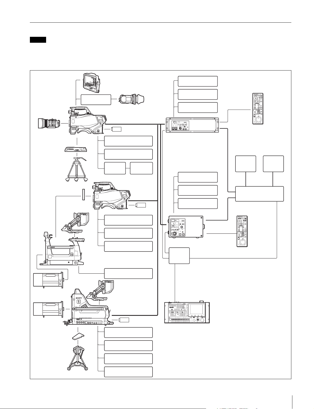
System Configuration
Note
Production of some of the peripherals and related devices shown in the figures has been discontinued. For advice on choosing
devices, please contact your Sony dealer or a Sony sales representative.
Connection example
HDVF-550/C730W/C550W/EL75
Zoom Lens
(for ENG/EFP)
VCT-14
Tripod Attachment
Tripod
Camera hangers
HDVF-EL70
HDVF-700A
Viewfinder
BKW-401 Viewfinder
Rotation Bracket
a)
Viewfinder
HDC2500
HDC2400
Optical Fiber Cable
USB drive
Return Video Selector
CAC-6
Intercom Headset
CAC-12
Microphone
holder
CAC-6
Return Video Selector
HDVF-20A
HDVF-200
HDVF-C30WR
HDVF-C35W
Viewfinder
Microphone
HDC2500
HDC2400
USB drive
HDCU2000
Camera Control Unit
LAN cable
HKCU1001
HKCU1003
HKCU2007
HKCU1001
HKCU1003
HKCU2007
CCA-5
RCP-1000-series
Remote Control Panel
BNC
Picture
Monitor
Video Router
BNC
Waveform
Monitor
Zoom lens
(for studio use)
V-wedge shoe
(supplied with
tripod)
Tripod
HDLA1500-series
Large Lens Adaptor
Zoom Lens
(for studio use)
Intercom Headset
Microphone
BKP-7911 Script Holder
Viewfinder
HDVF-EL70
HDVF-700A
HDC2000
USB drive
CAC-6
Return Video Selector
Intercom Headset
Microphone
BKP-7911 Script Holder
HDCU2500
Camera Control Unit
Hub
LAN cable
MSU-1000-series
Master Setup Unit
a) Supplied with HDLA1500-series Large Lens Adaptor
Part number: A-1128-405-A
CCA-5
RCP-1000-series
Remote Control Panel
Overview
9
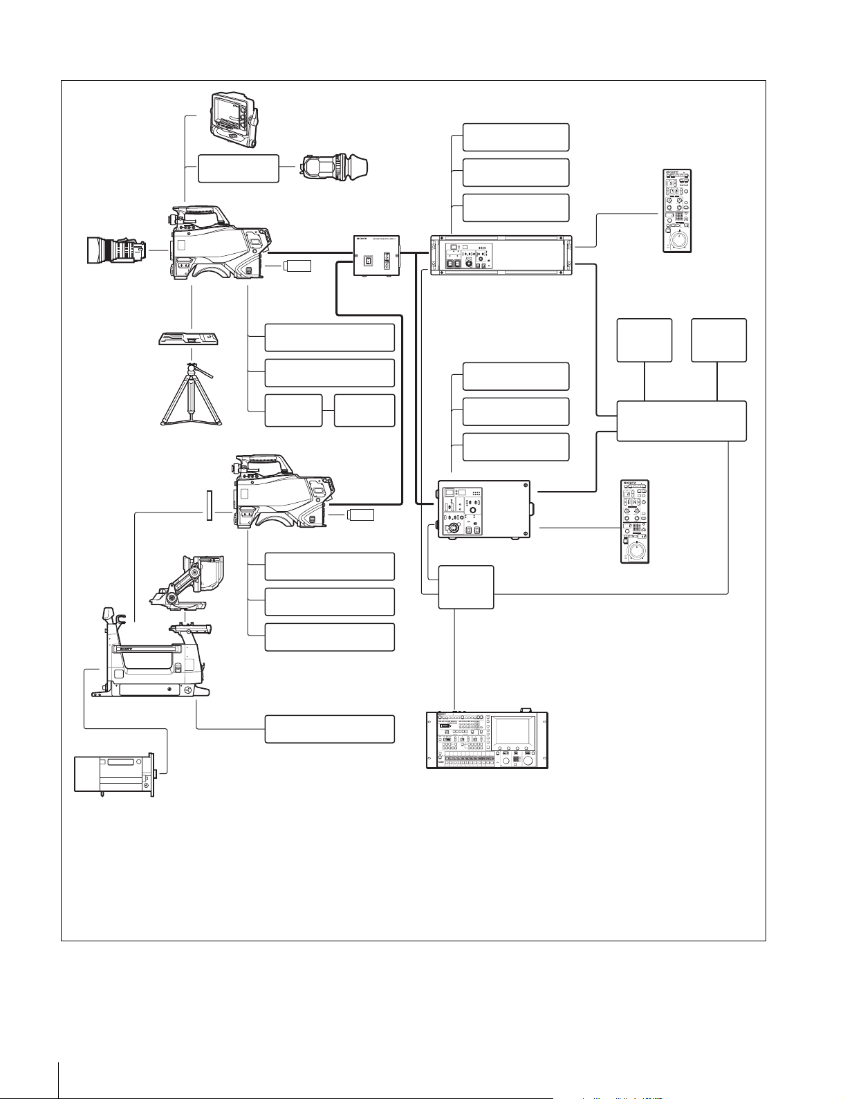
Connection example 2 (HDC2550)
HDVF-550/C730W/C550W
Viewfinder
BKW-401
Viewfinder
Rotation Bracket
Zoom Lens
(for ENG/EFP)
VCT-14
Tripod
Attachment
HDC2550
USB drive
CAC-6
Return Video Selector
Triax Cable
HDVF-20A
HDVF-200
HDVF-C30WR
HDVF-C35W
Viewfinder
HDFX100
HD Triax
CCU Adaptor
b)
Optical Fiber
Cable
a)
/EL75
a)
HDCU2000 HD Camera
Control Unit
HKCU1001
HKCU1003
HKCU2007
CCA-5
RCP-1000-series
Remote Control Panel
BNC
Picture
Monitor
Waveform
Monitor
Tripod
Camera hangers
HDVF-EL70/700A
Viewfinder
c)
HDLA1500-series
Large Lens Adaptor
Intercom Headset
CAC-12
Microphone
holder
Microphone
HDC2550
Triax cable
USB drive
CAC-6
Return Video Selector
Intercom Headset
Microphone
BKP-7911 Script Holder
HKCU1001
LAN cable
HKCU1003
Video Router
HKCU2007
b)
HDCU2500
Camera Control Unit
Hub
LAN cable
CCA-5
BNC
RCP-1000-series
Remote Control Panel
10
MSU-1000-series
Master Setup Unit
Zoom Lens
(for studio use)
a) The HDVF-550/C730W/C550W and HDVF-C35W function as
monochrome viewfinders when monitoring a return video with the
HDC2550.
b) The maximum Triax cable length between the HDC2550 and the
HDFX100 depends on the type of cable.
For details, refer to the Operation Manual of the HDFX100.
c) Supplied with HDLA1500-series Large Lens Adaptor
Part number: A-1128-405-A
Overview
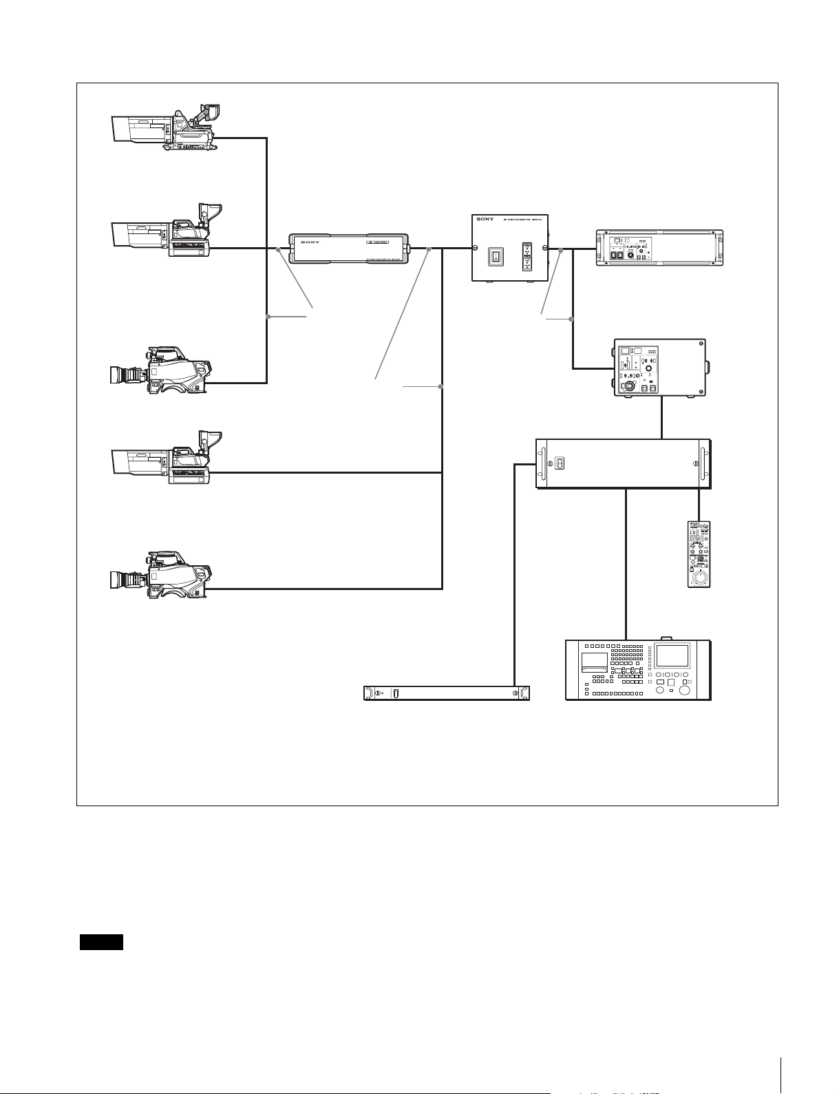
Connection example 3
HDC2000
HD Color Video Camera
+Large Lens Adaptor
HDTX100
HD Triax Camera Adaptor
HDFX100
HD Triax CCU Adaptor
HDCU2000
HD Camera Control Unit
HDC2500/2400
HD Color Video Camera
+Large Lens Adaptor
HDC2500/2400
HD Color Video Camera
HDC2550 HD Color Video Camera
+Large Lens Adaptor
+HDVF-C730W/C950W Electronic Viewfinder
HDC2550 HD Color Video Camera
1)
2)
Optical fiber
cable
Tr i a x c a bl e
Optical fiber
cable
HDCU2500
HD Camera Control Unit
CNU-700 Camera
Command Network Unit
RCP-1000-series
Remote Control Panel
VCS-700 Video Selector
Maximum cable run with Triax cable
The maximum Triax cable length between the HDC2500/
2400/2550 and the HDFX100 or between the HDFX100 and
the HDTX100 depends on the type of cable.
For details, refer to the Operation Manual of the HDFX100/
HDTX100.
Notes
• The viewfinders function as monochrome viewfinders when
monitoring a return video using the HDFX100 and the
HDTX100.
MSU-1000/1500 Master Setup Unit
1) HDC2500 with Large Lens Adaptor attached is illustrated.
2) HDC2500 is illustrated.
• The skin gate signal is superimposed on the camera video
signal. When tally becomes ON, the skin gate signal is
forced to OFF.
Overview
11
Locations and Functions of Parts
H
Accessory Attachments
D
H
ERIES
T S
A
RM
LTI F O
U
M
qd
qs
a VF (viewfinder) connector (20-pin)
Connect the cable of the viewfinder (not supplied).
1
2
3
4
5
6
7
8
9
0
qa
j LENS connector (12-pin)
Connect the lens cable. The camera can control the lens
functions through this cable.
k Tripod mount
Attach the VCT-14 Tripod Attachment when mounting the
camera on a tripod.
l Camera number
Insert the supplied camera number label. You can display the
camera number.
I
T
L
U
M
m Shoulder pad
You can adjust the position so that you can get the best
balance for shooting with the camera on your shoulder.
For details, see “Adjusting the Shoulder Pad Position” on page
22.
b Shoulder strap fitting post
Attach one end of a shoulder strap (not supplied) to this fitting
post, and the other end to the fitting post on the other side of
the camera.
c Accessory shoe
To attach an accessory using a 1/4-inch screw.
d Viewfinder left-right positioning ring
Loosen this ring to adjust the viewfinder position towards the
left or right.
e Viewfinder front-rear positioning lever and lock knob
Loosen the lever and knob to adjust the viewfinder position
towards the front or rear.
For details on adjusting the viewfinder position, see “Attaching
a Viewfinder” on page 19.
f Lens cable clamp
To secure the cable of the lens (not supplied).
g Lens fixing lever
To secure the lens in the lens mount.
h Lens mount cap
The cover can be removed by moving the lens fixing lever
upwards. Always keep the lens mount covered with this cap
when a lens is not attached.
i Lens mount
To attach a lens.
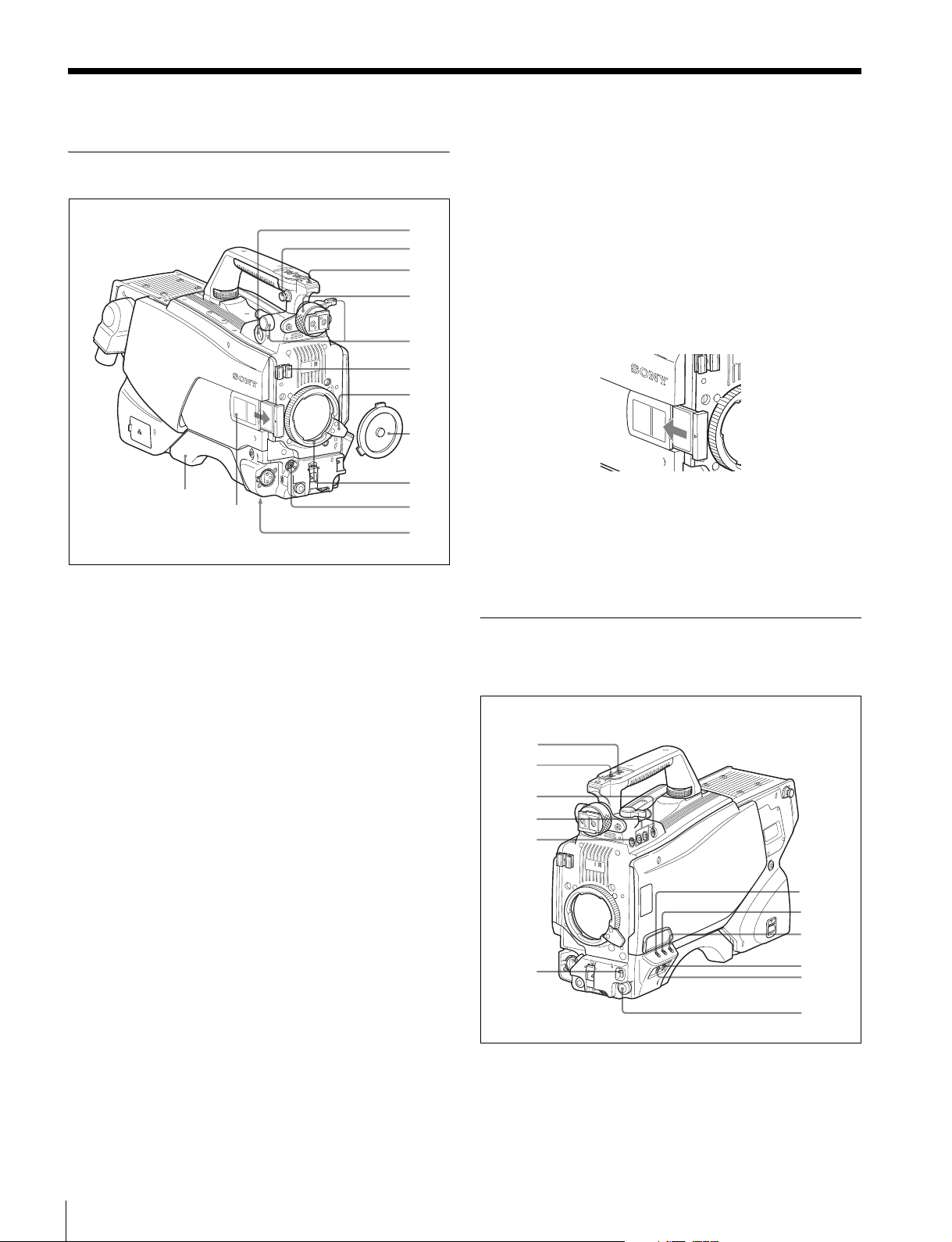
Controls and Connectors
Front right
1
2
3
4
5
HD
MULTI FORMAT SERIES
7
8
9
6
a INCOM (intercom 1) button
The intercom 1 microphone is turned ON while this button is
held pressed.
You can also assign other functions to this button, using the
menu displayed on the viewfinder screen.
0
qa
qs
Locations and Functions of Parts
12

b RET 1 (return video 1) button
The return video 1 signal from the camera control unit is
monitored on the viewfinder screen while this button is
pressed. It function the same as the RET 1 button on the side
(page 14) and that on the operation panel on the rear of the
camera (page 16 or 17).
You can also assign other functions to this button, using the
menu displayed on the viewfinder screen.
c Assignable switch
You can assign a function using the menu displayed on the
viewfinder screen.
d Filter select buttons
HDC2500/2550
You can switch the built-in ND and CC (color temperature
conversion) filters by pressing the selectors while holding the
FILTER LOCAL button depressed.
Pressing the left button selects the available ND filters (clear,
1/4ND, 1/8ND, 1/16ND,1/64ND) in sequence. Pressing the
right button selects the available CC filters (cross, 3200K,
4300K, 6300K, 8000K) in sequence.
HDC2400
You can switch the built-in optical filters (clear, 1/4ND,
1/16ND,1/64ND, cross) by pressing either of these buttons
while holding the FILTER LOCAL button depressed.
e FILTER LOCAL button
While holding this button depressed, press either of the filter
select buttons to select the built-in optical filters.
i WHITE BAL (white balance memory selection) switch
To select the white balance adjustment method or the memory
used to store the adjusted value when the camera is used in
standalone status without connecting a camera control unit.
PRST (preset): White balance is adjusted to a preset value
corresponding to a color temperature of 3200K.
A or B: Selects memory A or B.
j DISPLAY switch
The functions of the DISPLAY switch are as follows:
DISPLAY: Characters and messages showing the camera
settings and operating status may be displayed on the
viewfinder screen.
OFF: Status messages will not appear on the viewfinder
screen.
MENU: Menus for camera settings will be displayed on the
viewfinder screen.
k STATUS/CANCEL switch
STATUS: When no menu is displayed on the viewfinder
screen, the status information of this camera is displayed.
CANCEL: When a menu is displayed on the viewfinder
screen, you can cancel any changed settings or return
the display to the previous menu.
l MENU SEL (menu select) knob/ENTER button (rotary
encoder)
To select settings from menus displayed on the viewfinder
screen (by rotating the knob) and to confirm settings (by
pushing the button).
f AUTO W/B BAL (white and black balance automatic
adjustment) switch
To automatically adjust white and black balance when the
camera is used in standalone status without connecting to the
camera control unit.
WHT: Automatically adjust white balance.
BLK: Automatically adjust black balance.
g GAIN switch
To select the gain of the video amplifier based on lighting
conditions when the camera is used in standalone status
without connecting a camera control unit.
When shipped from the factory, the values set are L = 0 dB, M
= 6 dB, and H = 12 dB.
h OUTPUT (output signal selection)/AUTO KNEE switch
To select the signal (color bar signal or camera’s video signal)
to be used as output to a VTR, the viewfinder or a video
monitor when the camera is used in standalone status without
connecting a camera control unit.
When the camera’s video signal is being used as output, the
auto knee function may be used.
The relationship between the switch setting and the output
signal and auto knee function is shown in the table below.
OUTPUT AUTO KNEE Function
BARS OFF Output is a color bar signal.
CAM OFF Output is the camera’s video signal.
The auto knee circuit is disabled.
CAM ON Output is the camera’s video signal.
The auto knee circuit is enabled.
Note
When a camera control unit or a remote control device, such
as an MSU or RCP-series Remote Control Panel, is
connected, the functions of 6 to 9 are controlled from the
external control device and the controls on the camera are
disabled.
Locations and Functions of Parts
13

Front left
1
2
3
4
OFF: Not to supply a power to the connected microphone.
e SHUTTER switch
For setting the electronic shutter functions when the camera is
used in standalone status without connecting a camera control
unit.
OFF: The electronic shutter does not function.
ON: The electronic shutter is activated.
SEL: The shutter speed and shutter mode change each time
D
H
IES
ER
T S
A
TI FORM
L
U
M
the switch is set to this position.
For details, see “Setting the Electronic Shutter” on page 26.
f INTERCOM LEVEL control
To adjust the intercom/earphone volume level.
The intercom level adjustment is enabled when the
5
6
7
INTERCOM 1 and 2 LEVEL/MIC switches (on the SY-type
operation panel, page 15) or the LEVEL switch (on the
European-type operation panel, page 17) on the rear of the
camera are set to “FRONT.”
a NETWORK TRUNK connector (RJ-45 8-pin) (HDC2500/
2400)
Connects a device connected to the CCU’s NETWORK
TRUNK connector to the network.
Caution
• For safety, do not connect the connector for peripheral
device wiring that might have excessive voltage to this port.
Follow the instructions for this port.
• When you connect the LAN cable of the unit to peripheral
device, use a shielded-type cable to prevent malfunction
due to radiation noise.
ATTENTION
Par mesure de sécurité, ne raccordez pas le connecteur pour
le câblage de périphériques pouvant avoir une tension
excessive à ce port. Suivez les instructions pour ce port.
VORSICHT
Aus Sicherheitsgründen nicht mit einem PeripheriegerätAnschluss verbinden, der zu starke Spannung für diese
Buchse haben könnte. Folgen Sie den Anweisungen für diese
Buchse.
b RET 1 (return video 1) button
The return video 1 signal from the camera control unit is
monitored on the viewfinder screen while this button is
pressed. It function the same as the RET 1 buttons on the
handle (page 13) and that on the operation panel on the rear
of the camera (page 16 or 17).
You can also assign other functions to this button, using the
menu displayed on the viewfinder screen.
c MIC 1 IN (microphone 1 input) connector (XLR 3-pin)
Connect a microphone.
This connector and the AUDIO IN CH-1 connector (page 18)
on the operation panel on the rear of the camera are
alternately activated with the CH1 audio input select switch
(page 18).
g RET 2 (return video 2) button
When this button is pressed, the picture on the viewfinder
screen changes to the return video signal selected with the
RET 2 select switch (page 15 or 16) on the operation panel on
the rear of the camera.
You can also assign other functions to this button, using the
menu displayed on the viewfinder screen.
Rear
3
Shoulder strap fitting
post (page 12)
Operation panel
(page 15)
4
5
6
1
2
a DC power supply out connector (2-pin)
Supplies power to an external device up to 2.5 A.
b CAMERA POWER switch
CCU: Power is supplied from the camera control unit.
EXT: Power is supplied through the DC IN connector.
7
Connector panel
(page 17)
8
d MIC (microphone) power switch
+48V: To supply a power of +48 V to the connected
microphone.
Locations and Functions of Parts
14
c Tally lamp and switch
ON: The tally lamp lights when a tally signal is input to the
connected camera control unit or a call signal is
generated in response to pressing of a CALL button.
OFF: The tally lamp is prevented from lighting.
d CCU (Camera Control Unit) connector (optical/
electrical multi-connector) (HDC2500/2400)
Connect a camera control unit using an optical electrocomposite cable.
d HDFX (HD Triax CCU) connector (Triax connector)
(HDC2550)
Connect the HDFX100 HD Triax CCU Adaptor using a Triax
cable. A camera control unit can be connected via the
HDFX100.
e SDI 1 (serial digital interface 1) connector (BNC-type)
(HDC2500/2400)
For 3G-SDI, HD-SDI or HD PROMPTER signal output.
f SDI 2 (serial digital interface 2) connector (BNC-type)
(HDC2500/2400)
For HD-SDI signal output or HD TRUNK signal input. During
stand-alone operation, also used for inputting an HD-SDI
return signal. When RET (return) is set to 1, this is displayed
in the viewfinder.
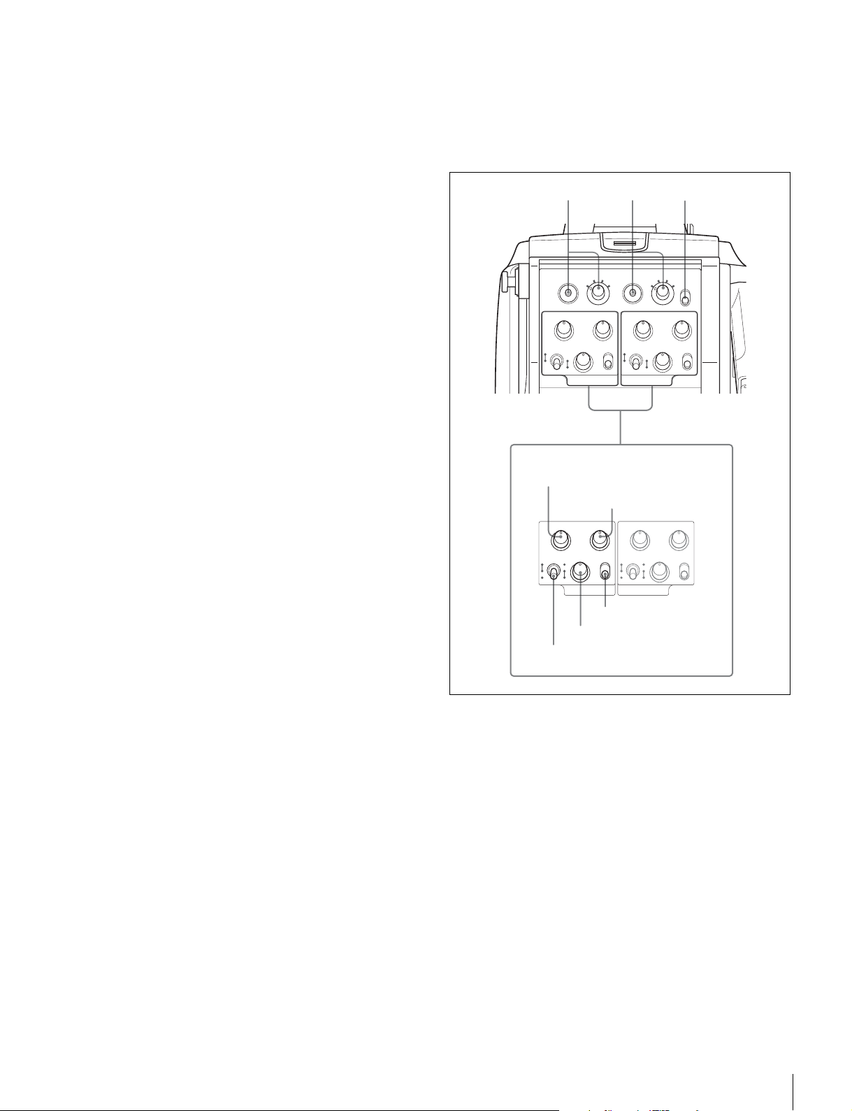
Operation panel
SY type: For JN/SY/UC (USA, Canada, East Asia and other
countries) models (for NTSC areas)
For details on the differences among models, see “Overview”
on page 5.
234
a
RET1
PGM1 PGM2
LEVEL
MIC
REAR
ON
FRONT
OFF ENG
INTERCOM 1
1
INCOM
23
PROD
4
23
RET2
1
PGM1 PGM2
LEVEL
MIC
REAR
ON
FRONT
OFF ENG
INTERCOM 2
INCOM
LIGHT
4
ON
OFF
PROD
g PROMPTER2 connector (BNC-type) (HDC2500/2400)
For prompter 2 signal output
Available only when connecting a camera control unit with a
prompter 2 input connecter.
During stand-alone operation, also used for inputting a VBS
return signal. When RET (return) is set to 2, this is displayed
in the viewfinder.
h CALL button
When this button is pressed, the red tally lamp of the RCP1000-series Remote Control Panel or the MSU-1000-series
Master Setup Unit will light. Use to call the operator of the RCP
or MSU.
PGM1 control
PGM2 control
PGM1 PGM2
LEVEL
MIC
REAR
ON
FRONT
OFF ENG
INTERCOM 1
INCOM
PROD
PGM1 PGM2
LEVEL
MIC
REAR
ON
FRONT
OFF ENG
INTERCOM 2
INCOM
PROD
Line select switch
INCOM level control
LEVEL/MIC switch
a INTERCOM1 and INTERCOM2 controls and switches
There are PGM1 and 2 controls incorporated with a line select
switch, a LEVEL/MIC switch, and INCOM level control each
for intercom line 1 and 2.
PGM1 (program 1) control
Adjust the audio listening level of program 1.
PGM2 (program 2) control
Adjust the audio listening level of program 2.
LEVEL/MIC switch
REAR/ON: The intercom headset microphone is turned on.
The intercom audio listening level is adjusted with the
INCOM level control.
REAR/OFF: The intercom headset microphone is turned off.
The intercom audio listening level is adjusted with the
INCOM level control.
Locations and Functions of Parts
15

FRONT/OFF: The intercom headset microphone is turned off.
The intercom audio listening level is adjusted with the
INCOM level control and the INTERCOM LEVEL control
on the front of the camera (page 14).
INCOM level control
Adjust the intercom audio listening level.
Line select switch
Select the intercom line.
PROD: Producer line
ENG: Engineer line
b RET 1 (return video 1) button and select switch
Press the button to display the return video signal selected
with the switch on the viewfinder screen.
European type: For CE (Europe) and E (China and South
Asia) models (for PAL areas)
For details on the differences among models, see “Overview”
on page 5.
234
23
RET1
1
ENG PROD
4
23
RET2
1
PGM1 PGM2
LIGHT
4
ON
OFF
c RET 2 (return video 2) button and select switch
If you use an additional return video system in addition to
return video 1, press the button to display the return video
signal selected with the switch on the viewfinder screen.
Note
The RET 1 button has priority over the RET 2 button if both
buttons are pressed.
If RET 1 and RET 2 buttons are pressed at the same time, the
two buttons function as the RET 3 button when setting
<RETURN> 12 of the OPERATION menu.
d LIGHT switch
Set to ON to illuminate the operation panel.
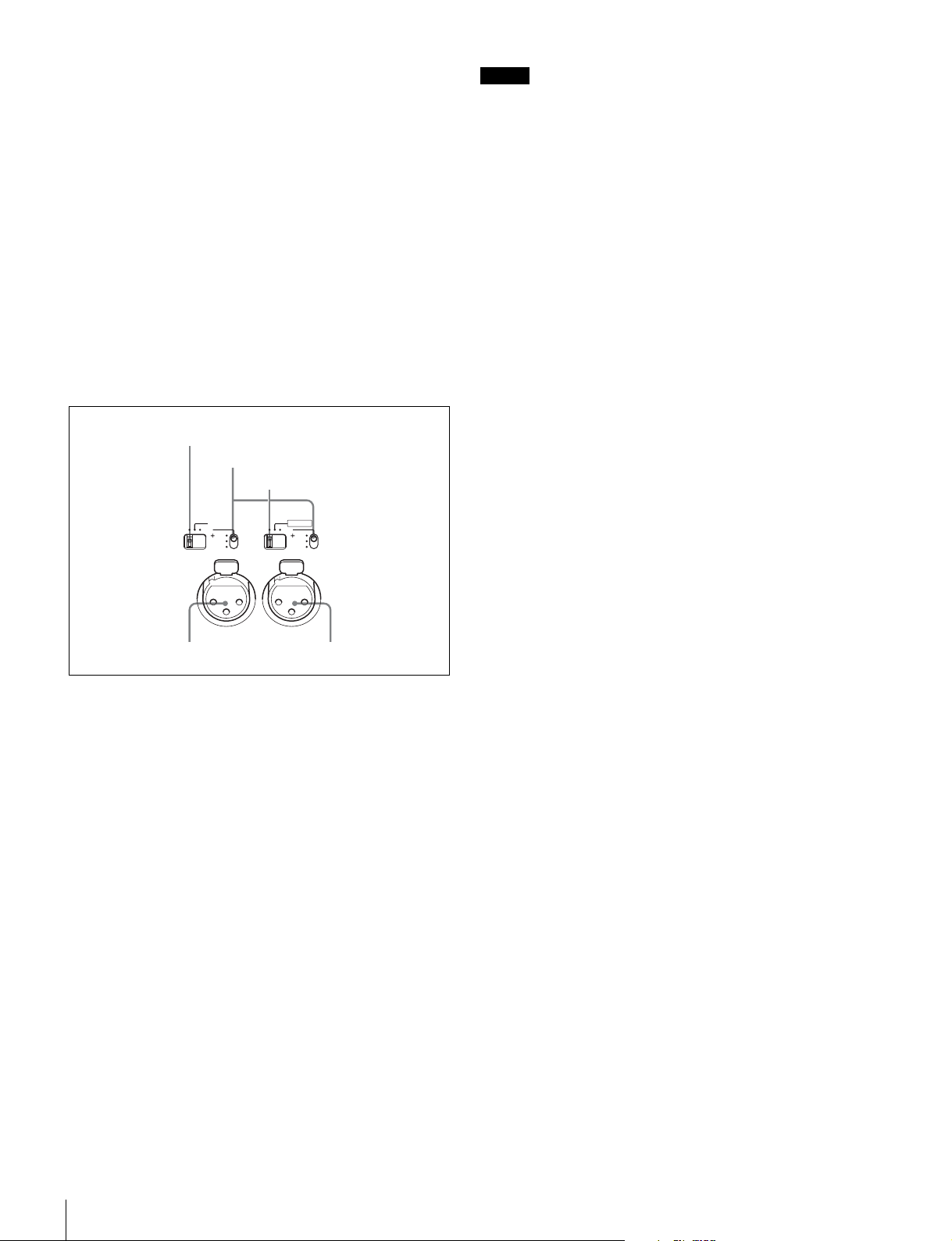
MIC
LINE1
PROD
OFF
ENG
INTERCOM 1
MIC
PROD
LINE2
ENG
INTERCOM 2
LEVEL
TRACKER
REAR
OFF
FRT
a
PGM2 control
PGM1 control
PROD control
ENG control
ENG PROD
MIC
PROD
LINE1
OFF
ENG
INTERCOM 1
PGM1 PGM2
MIC
TRACKER
PROD
LINE2
OFF
ENG
INTERCOM 2
LEVEL
REAR
FRT
MIC LINE1 switch
MIC LINE2 switch
TRACKER control
LEVEL switch
a INTERCOM1 and INTERCOM2 controls and switches
The reception level controls are common to intercom 1 and
intercom 2. The talk lines can be set independently for
intercom 1 and intercom 2.
Locations and Functions of Parts
16
ENG (engineer line) control:
Adjust the intercom audio listening level of the engineer line.
PROD (producer line) control
Adjust the intercom audio listening level of the producer line.
PGM1 (program 1) control
Adjust the audio listening level of program 1.
PGM2 (program 2) control
Adjust the audio listening level of program 2.
TRACKER control
Adjust the intercom audio listening level at the TRACKER
connector (page 17) on the connector panel when using the
connector for intercom.
MIC LINE1 (intercom microphone line 1) switch
Select the talk line for intercom 1.
PROD: To talk over the producer line

OFF: To turn off the headset microphone for intercom line 1.
OFF
+48V
MIC
FRONT MIC
PROMPTER
/GEN
LOCK
RET CTRL
AUDIO IN
CH1 CH2
TEST
OUT
SDI
MONI
DC IN 10.5-17V
LINE
OFF
+48V
MIC
AES/EBU
LINE
EARPHONE
REMOTE
DC OUT
CRANETRACKER
ENG: To talk over the engineer line
MIC LINE2 (intercom microphone line 2) switch
Select the talk line for intercom 2.
PROD: To talk over the producer line
OFF: To turn off the headset microphone for intercom line 2.
ENG: To talk over the engineer line
LEVEL switch
REAR: The intercom audio listening level is adjusted with the
controls on this panel.
FRT: The intercom audio listening level is adjusted with the
INTERCOM LEVEL control on the front of the camera.
b RET 1 (return video 1) button and select switch
The return video signal selected with the switch is displayed
on the viewfinder screen while the button is pressed.
c RET 2 (return video 2) button and select switch
When other return video systems are used in addition to return
video 1, you can monitor the signal selected with the switch on
the viewfinder screen while pressing the button.
Note
The RET 1 button has priority over the RET 2 button if both
buttons are pressed.
If RET 1 and RET 2 buttons are pressed at the same time, the
two buttons function as the RET 3 button when setting
<RETURN> 12 of the OPERATION menu.
d LIGHT switch
Set to ON to illuminate the operation panel.
Connector panel
1
2
3
4
5
6
7
qd
a EARPHONE jack (stereo minijack)
For connecting an earphone or headset to hear the intercom
audio.
b DC OUT (DC power supply output) connector (4-pin)
To supply power to devices such as a wireless receiver
(optional) (max. 0.5 A).
8
9
0
qa
qs
c CRANE connector (12-pin)
For external interface, such as viewfinder (and external data
with HDC2500/2400).
d USB connector (for connecting a USB drive)
Connect a USB drive to save or load the settings data file.
For details, see “Using a USB drive” (page 62).
e TRACKER connector (10-pin)
For external interface, such as intercom and tally.
f RET CTRL (return control) connector (6-pin)
For connection to a CAC-6 Return Video Selector.
g DC IN (DC power supply input) connector (XLR 4-pin)
Used for connection to the AC-DN10 AC Adaptor to supply
power to the camera.
h INTERCOM1 and 2 (intercom 1 and 2) connectors (XLR
5-pin)
Used for input and output of intercom audio signals if an XLR
5-pin headset is connected.
The INTERCOM 1 connector can be used for communication
over the engineer line even when the power is off, as long as
the power LED is lit in red.
i REMOTE connector (8-pin)
For connection to an RCP-1000/1500-series Remote Control
Panel, or MSU-1000/1500 Master Setup Unit.
Note
When the camera is connected to a CCU, do not connect any
remote control device, such as RCP and MSU, to this
connector.
j PROMPTER/GENLOCK (prompter 1 signal output/
external gen-lock signal input) connector (BNC-type)
The PROMPTER function is available only when a camera
control unit is connected.
The GENLOCK IN function and RET IN function are available
when a camera control unit is not connected.
GENLOCK IN: For input of an external gen-lock signal (VBS
or 3-level sync) during stand-alone operation.
RET IN: For input of the return video signal during stand-alone
operation.
The connector accepts analog HD signals only. SDI
signals are not acceptable. Supply a signal of 1080i
(720P is not acceptable).
The signal supplied to this connector cannot be fed as
RET OUT from the TEST OUT or SDI OUT connector.
This is displayed in the viewfinder regardless of which
RET is selected. CHARACTER will not be overlapped for
the displayed RET 3 signal.
PROMPTER: For output of the prompter 1 signal (valid only
when a camera control unit is connected). When a
camera control unit having two prompter inputs is
connected, the signal of input 1 is output from this
connector.
Locations and Functions of Parts
17
k TEST OUT connector (BNC-type)
To output the analog signal.
This also supplies the VBS signal, an HD signal nearly equal
to the signal output from the VF connector, an HD-SYNC
signal, or an SD-SYNC signal depending on which of these
you have selected on the menu.
For details on the output signals, see “Setting the Camera
Outputs” (page 29).
l SDI-MONI (serial digital interface) connector (BNC-
type)
For HD-SDI or SD-SDI signal output.
For details on the output signals, see “Setting the Camera
Outputs” (page 29).
m AUDIO IN CH1 and CH2 connectors (XLR 3-pin) and
switches
Connect audio signals. An input select switch and microphone
power switch are provided for each channel.
CH1 audio input select switch
Microphone power switches
CH2 audio input select switch
Note
To supply +12 V power, contact a Sony sales representative
or Sony service representative.
FRONT MIC
MIC
LINE
48V
OFF
AUDIO IN
CH 1
AUDIO IN CH1 connector AUDIO IN CH2 connector
LINE
AES/EBU
MIC
48V
OFF
CH 2
CH1 audio input select switch
Set to the appropriate position according to the equipment
connected to the AUDIO IN CH1 connector.
LINE: When a line-level (0 dBu) signal source is connected
FRONT MIC: When using the microphone connected to the
MIC 1 IN connector
MIC: When an external microphone is connected
CH2 audio input select switch
Set to the appropriate position according to the equipment
connected to the AUDIO IN CH2 connector.
LINE: When a line-level (0 dBu) signal source is connected
AES/EBU: When a digital audio signal is connected (The
signal must be in synchronization with the camera
output). With HDC2550, the signal will not be transmitted
to CCU.
MIC: When an external microphone is connected
Microphone power switches
When a microphone is connected to the corresponding AUDIO
IN connector, set whether or not to supply a power to the
microphone.
+48V: To supply a power of +48 V
OFF: Not to supply a power
(No function has been assigned to the lowermost position. No
power is supplied to the microphone.)
Locations and Functions of Parts
18
Preparations
Note
The various parts of the lens used in adjusting the flange focal
length are in different positions on different lenses. Refer to
the operation manual for the particular lens.
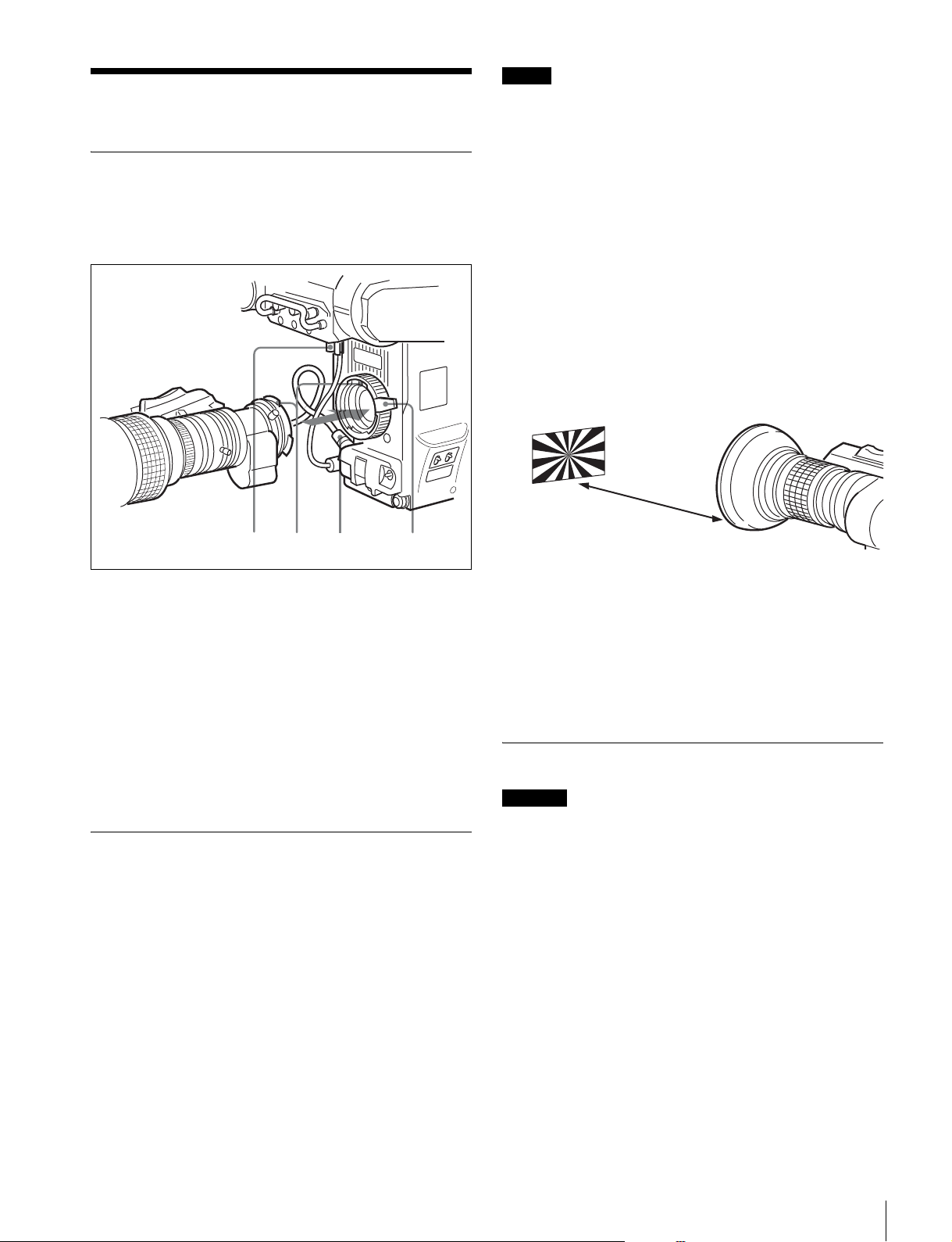
Attaching a Lens
For information on handling lenses, refer to the lens’ operation
manual.
Attaching procedure
1,3425
1 Push the lens fixing lever upwards and remove the
lens mount cap from the lens mount.
2 Align the lens’ alignment pin with the notch in the
upper part of the lens mount and insert the lens into
the mount.
Adjusting procedure
1 Set the iris control to manual, and open the iris fully.
2 Place a flange focal length adjustment chart
approximately 3 meters from the camera and adjust
the lighting to get an appropriate video output level.
3 Loosen the Ff (flange focal length) ring lock screw.
4 With either manual or power zoom, set the zoom ring
to telephoto.
5 Aim at the flange focal length adjustment chart and
turn the focus ring to focus the image.
About 3 meters (10 ft)
6 Set the zoom ring to wide angle.
7 Turn the Ff ring to bring the chart into focus. Take
care not to move the distance ring.
8 Repeat steps 4 through 7 until the image is in focus at
both telephoto and wide angle.
3 While supporting the lens, push the lens fixing lever
downwards to secure the lens.
4 Connect the lens cable to the LENS connector.
5 Secure the lens cable with the cable clamp.
Adjusting the Flange Focal Length
Adjustment of the flange focal length (the distance between
the lens mount attachment plane and the imaging plane) is
necessary in the following situations:
• The first time a lens is attached
• When changing lenses
• If the focus is not sharp at both telephoto and wide angle
when zooming
The flange focal length can be more precisely adjusted by
using the focus assist indicators.
See “Displaying the focus assist indicators” on page 28 for the
focus assist indicators.
9 Tighten the Ff ring lock screw.
Attaching a Viewfinder
Caution
When the viewfinder is attached, do not leave the camera with
the eyepiece facing the sun. Direct sunlight can enter through
the eyepiece, be focused in the viewfinder and cause fire.
Attaching a viewfinder
The instructions are made using the HDVF-20A/200/C30WR/
C35W viewfinder as an example.
For details on the viewfinder, refer to the instruction manual of
the viewfinder.
Preparations
19
VF connector
Viewfinder stopper
D
H
S
RIE
T SE
A
RM
LTI F O
U
M
MIC 1 IN connector
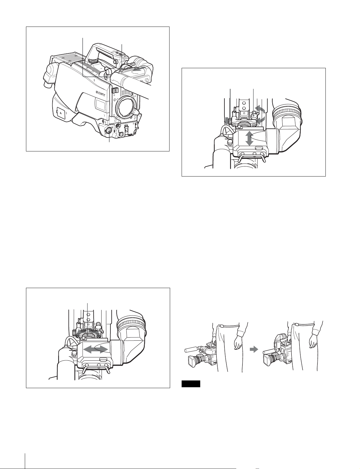
1 Slide the viewfinder in the direction of the arrow.
The viewfinder stopper automatically pops down.
2 Slide the viewfinder left or right to move it into a good
viewing position.
3 Tighten the viewfinder left-right positioning ring.
To adjust the position forward or backward
Viewfinder front-rear
LOCK knob
positioning lever
2 Loosen the viewfinder left-right positioning ring, slide
the viewfinder side to side to the most convenient
position and tighten the ring. (See “To adjust the
position to the left or right” below.)
3 Connect the viewfinder cable to the VF connector of
the camera.
4 Connect the microphone cable to the MIC 1 IN
connector of the camera.
Adjusting the viewfinder position
The viewfinder position may be adjusted towards the front and
rear and to the left and right to make it easy to see into it.
To adjust the position to the left or right
Viewfinder left-right positioning ring
1 Loosen the viewfinder front-rear positioning lever
and LOCK knob.
2 Slide the viewfinder towards the front or rear of the
camera to move it into a good viewing position.
3 Tighten the viewfinder front-rear positioning lever
and LOCK knob.
Detaching the viewfinder
Loosen the viewfinder left-right positioning ring, pull the
viewfinder stopper, then pull out the viewfinder by sliding it in
the direction opposite to that when attached.
Keeping the viewfinder from hitting your leg
(using BKW-401)
To keep the viewfinder from bumping your leg when carrying
the camera, install the BKW-401 Viewfinder Rotation Bracket
(optional) and rotate the viewfinder upwards.
1 Loosen the viewfinder left-right positioning ring.
Preparations
20
Note
Lock the viewfinder in a slightly forward position before
rotating it upwards. If the viewfinder is in its rearmost position,
the arm of the viewfinder rotation bracket will strike the grip.
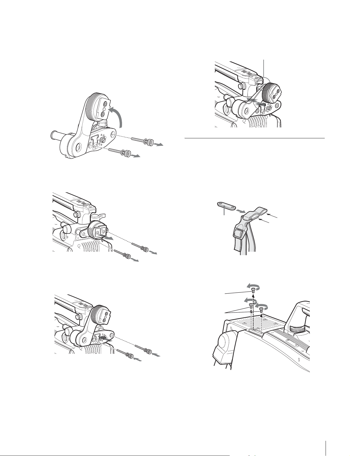
Attaching procedure of the BKW-401
1 Turn the arm of the rotation mechanism assembly of
the BKW-401 in the direction of the arrow in the
following illustration.
Next, using a hexagonal wrench 3 mm across flats,
remove the bolts (M4 × 8) together with the washers,
to separate the rotation mechanism assembly from
the viewfinder front-back positioning mechanism
assembly.
4 Adjust the front-rear position so that the camera
handle does not interfere when you rotate the BKW401 arm upwards.
Not to interfere
Attaching the Cable Clamp Belt (Supplied)
2 In the same manner as step 1, remove the viewfinder
shoe of the camera from the front-rear positioning
mechanism.
3 Using the two bolts (M4 × 8) and the washers removed
from the camera in step 2, attach the rotation
mechanism assembly of the BKW-401 to the camera.
Hexagon
socket bolts
(M4 × 8)
You can secure the camera cable to the camera by attaching
the supplied cable clamp belt.
1 Insert the belt bracket into hole A or B of the cable
clamp belt.
Belt bracket
B
A
2 Remove two +B3×5 screws and a blind screw shown
in the figure below from the camera.
Blind screw
×5 screws
+B3
Preparations
21
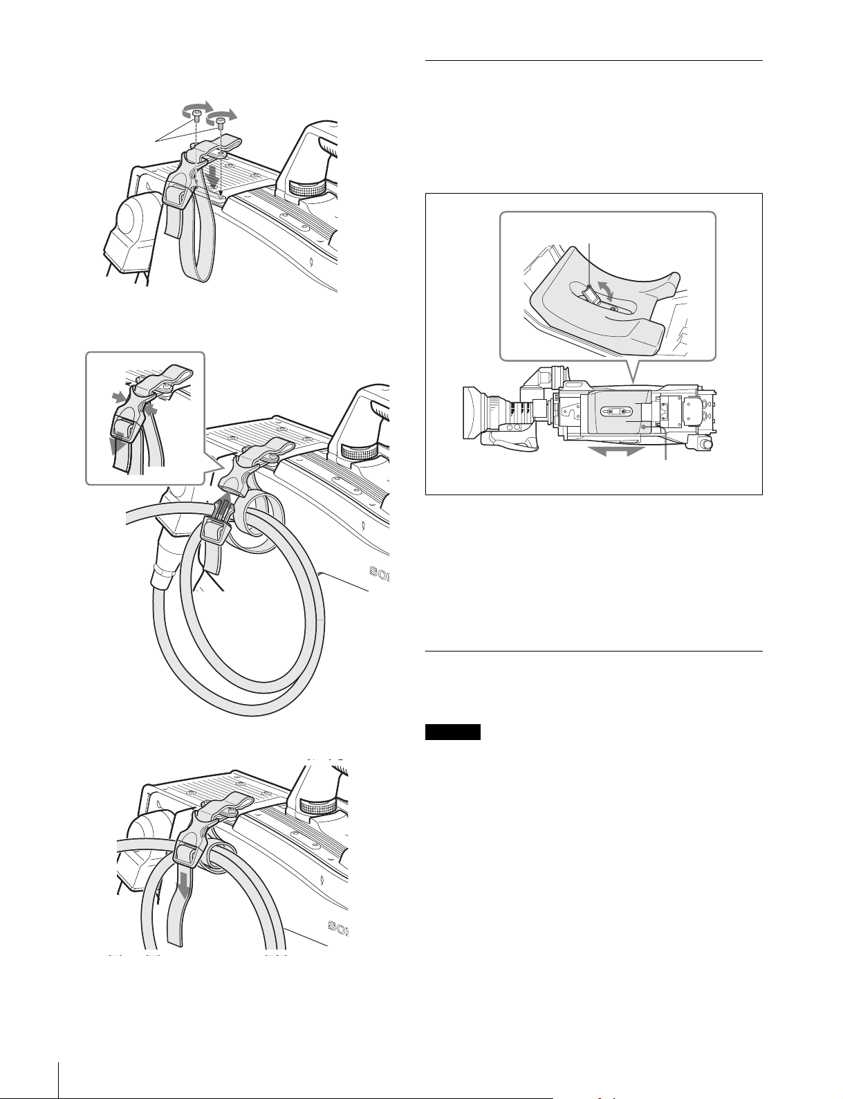
3 Secure the cable clamp belt to the camera, using the
two supplied +B3×8 screws.
+B3×8 screws
4 1 Release the buckle, 2 bundle the cable with the
belt, 3 then lock the buckle again.
1
Adjusting the Shoulder Pad Position
You can shift the shoulder pad from its center position (factory
setting) backward by up to 10 mm (3/8 inch) or forward by up
to 25 mm (1 inch). This adjustment helps you get the best
balance for shooting with the camera on your shoulder.
Adjusting procedure
Shoulder pad lock lever
1,3
3
2
Camera cable
5 Adjust the length by pulling down the end of the belt.
Bottom of the camera
2
Shoulder pad
1 Raise the lever in the center of the shoulder pad to
unlock the shoulder pad.
2 Slide the shoulder pad backward or forward until it is
in the most convenient position.
3 Move the lever down to lock the shoulder pad in the
selected position.
Mounting the Camera to a Tripod
Mount the camera to a tripod using a VCT-14 Tripod
Attachment.
Caution
• Select an appropriate hole from among those at the bottom
of the tripod attachment considering the balance of the
weight of the camera and the tripod attachment. If an
inappropriate hole is selected, the camera may fall over.
• Check that the size of the selected hole matches that of the
screw of the tripod. If they do not match, the tripod
attachment cannot be attached to the tripod securely.
22
Preparations
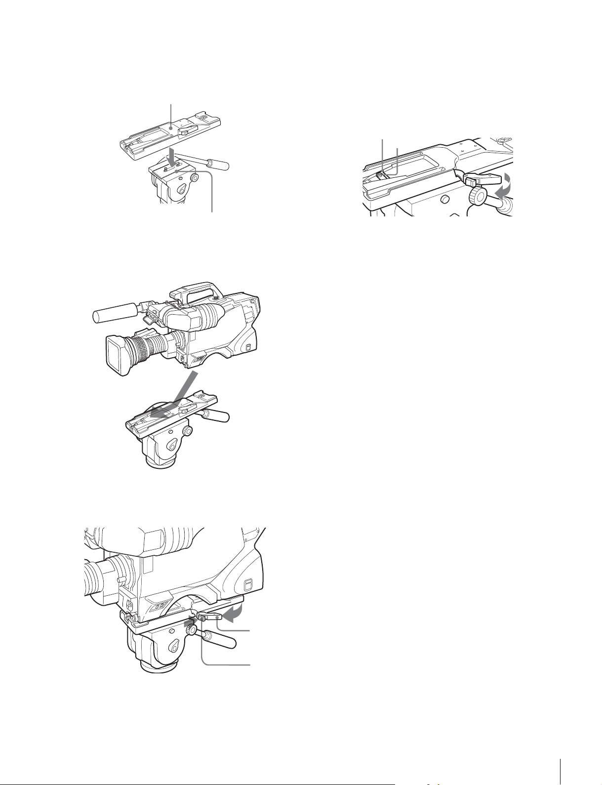
Mounting procedure
1 Attach the tripod attachment to the tripod and secure
it with the screw.
Tripod attachment
If the pin of the tripod attachment does not return to
its original position
After removing the camera, if the pin of the tripod attachment
does not return to its original position, hold down the red
button and move the lever in the direction of the arrow to return
the pin to its original position. It is not possible to mount a
camera with the pin not seated.
Platform of the tripod
2 Place the camera on the tripod attachment, and slide
forward it along the groove of the tripod attachment
until it clicks.
Original position
Pin
To remove the camera from the tripod attachment
Hold down the red button and pull the lever in the direction of
the arrow.
Lever
Red button
Preparations
23
Adjustments and
Automatic adjustment of black balance begins.
In automatic adjustment of black balance, both the black set
and black balance are adjusted.
Settings for Shooting
Adjusting the Black Balance and White Balance
In order to maintain high picture quality, it is necessary to set
the black balance and white balance appropriately for the
conditions.
Note
When a camera control unit or a remote control device-such
as the MSU or RCP series-is connected, control is performed
from the RCP/MSU, and the switches on the camera are
disabled.
Black balance adjustment
The black balance needs adjustment in situations like the
following:
• The first time the camera is used
• When the camera is used after a long period of disuse
• When the surrounding temperature changes greatly
• When the gain value is changed using the setup menus
Normally, there is no need to adjust the black balance every
time the camera is turned on.
White balance adjustment
Always readjust the white balance when lighting conditions
change.
About the viewfinder screen
After the process of adjusting the black balance or white
balance begins, messages about the progress and results of
the adjustment will be displayed on the viewfinder screen.
During adjustment, a message like the one in the figure below
will be displayed on the viewfinder screen.
ABB:EXECUTING
When the adjustment process is completed, the message
“ABB: OK” will be displayed. The adjusted value is
automatically stored in memory.
Notes
• During black balance adjustment, the iris will be
automatically closed.
• During black balance adjustment, the gain switching circuit
will work automatically, and the viewfinder screen will flicker
several times. This is not a malfunction.
When automatic black balance adjustment fails
If the automatic black balance adjustment process does not
end successfully, the error message “ABB: NG” will be
displayed on the viewfinder screen for approximately three
seconds.
If this error message is displayed, try black balance
adjustment again.
If the error message continues to be displayed after several
attempts, the camera requires internal inspection.
About black balance memory
The black balance values stored in memory will be preserved
even when the camera power is turned off.
Note
Adjusted values set through automatic adjustment, and other
settings, are stored in the camera’s memory and preserved
even when the camera power is turned off.
Adjusting the black balance
Push the AUTO W/B BAL switch toward BLK (downward).
AUTO W/B BAL switch
Adjustments and Settings for Shooting
24
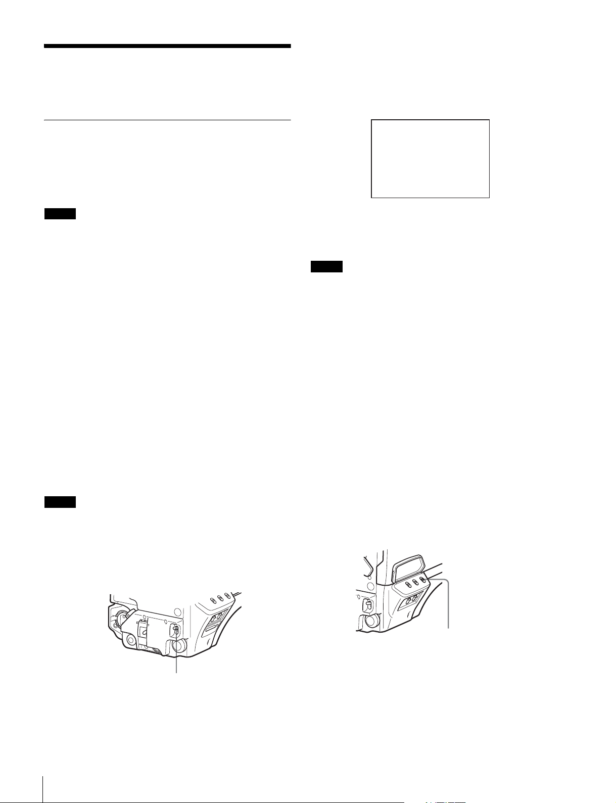
Adjusting the white balance
1 Set the WHITE BAL switch to A or B.
WHITE BAL switch
2 Select the filter setting according to the lighting
conditions.
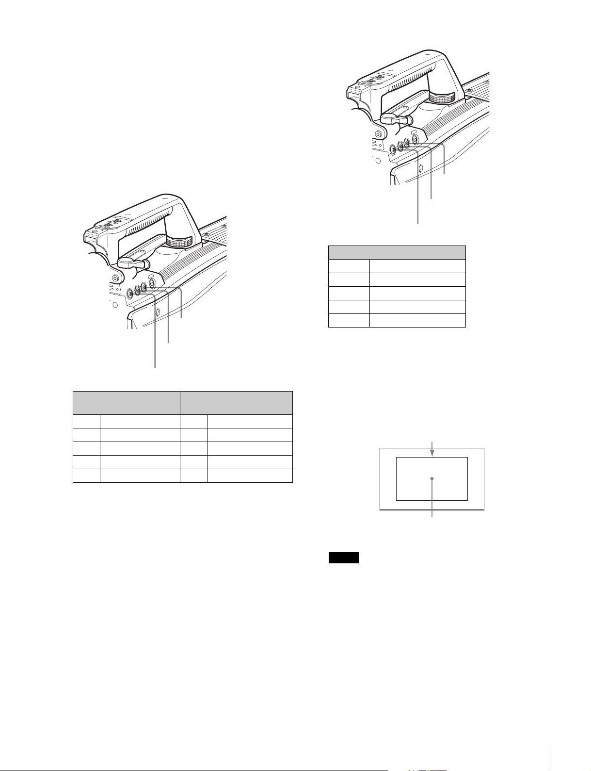
• HDC2500/2550
HD
MULTI FORMA
T SERIES
HD
MULTI FORMA
T SERIES
To select the ND filter
Press the ND filter select button while holding the FILTER
LOCAL button depressed.
Each press of the select button switches the available ND
filters (clear, 1/4ND, 1/8ND, 1/16ND,1/64ND) in
sequence.
To select the CC filter
Press the CC filter select button while holding the FILTER
LOCAL button depressed.
Each press of the select button switches the available CC
filters (cross, 3200K, 4300K, 6300K, 8000K) in sequence.
CC filter select button
Filter select DOWN button
Filter select UP button
FILTER LOCAL button
Optical filter
1 clear
21/4 ND
3 1/16 ND
4 1/64 ND
5cross
ND filter select button
FILTER LOCAL button
ND filter Color temperature
conversion filter
1 clear A cross filter
2 1/4 ND B 3200K (clear)
3 1/8 ND C 4300K
4 1/16 ND D 6300K
5 1/64 ND E 8000K
• HDC2400
Press the filter select UP or DOWN button while holding
the FILTER LOCAL button depressed.
Each press of the UP or DOWN button switches the
available optical filters in sequence.
3 Place a white pattern in the same lighting conditions
as the subject, and zoom in on it so that a white area
is obtained in the screen to satisfy the positional and
quantitative requirements illustrated below.
A white object (white cloth, a white wall, etc.) near the
subject may be used in place of a white pattern.
A rectangle centered in the screen. The length of the sides
must be at least 70% of the height and width of the screen.
Within this rectangle, there must be an area of white greater
than 10% of the entire screen.
Note
Be careful not to have any spots of high illumination in the
rectangle.
4 Adjust the lens iris opening.
With a manually adjusted lens: Set the opening to an
appropriate value.
With a lens which has automatic iris control: Set the
lens’ automatic/manual iris control switch to
automatic.
Adjustments and Settings for Shooting
25

5 Push the AUTO W/B BAL switch to WHT and release
the switch.
AUTO W/B BAL switch
The switch will return to the center position, and adjustment
will be performed.
During adjustment, the message “AWB: EXECUTING” will be
displayed on the viewfinder screen.
A message like the one in the figure below will be displayed,
and the adjustment process will complete. The adjusted value
will be automatically stored in the memory (A or B) selected in
step 1.
AWB:OK
Setting the Electronic Shutter
This section explains the different modes which can be used
for the electronic shutter and gives the procedures for setting
the shutter mode and shutter speed.
Note
When a camera control unit or a remote control device, such
as MSU-1000/1500 Master Setup Unit and RCP-1000/1500series Remote Control Panel, is connected, the electronic
shutter is controlled from the external control device and
control on the camera are disabled.
About the shutter modes
The shutter modes that can be used with the electronic shutter
of the camera and the shutter speeds that may be selected are
as follows:
Shutter modes and speeds
Shutter mode Shutter speeds* Usage
Standard 1/100, 1/125, 1/250,
ECS (Extended
Clear Scan)
1/500, 1/1000, 1/2000
seconds
Continuously variable in
the range of 60.00 Hz to
4300 Hz
Use to obtain clear images
of quickly moving subjects
Use to obtain images on
video monitors without
horizontal striping
Note
When using a zoom lens with automatic iris control capability,
1)
hunting
may occur. Adjust the lens’ iris gain control (labeled
IG, IS, S, etc.).
1)
Hunting: The automatic iris responds over and over, and the image
repeatedly darkens and lightens.
For more information, refer to the lens’ operation manual.
When automatic white balance adjustment fails
If the white balance adjustment process does not end
successfully, the error message “AWB: NG” will be displayed
on the viewfinder screen for approximately three seconds.
If this error message is displayed, try white balance
adjustment again.
If the error message continues to be displayed after several
attempts, the camera requires internal inspection.
When there is no time to adjust the white balance
Set the WHITE BAL switch to PRST. The white balance will be
set automatically according to the filter settings.
About white balance memory
The white balance values stored in memory will be preserved
even when the camera power is turned off.
There are two white balance memories, A and B. When the
AUTO W/B BAL switch is pushed to the WHT side, the white
balance will be adjusted automatically according to the filter
settings. The adjusted value will be stored in the selected
memory. Each memory can store up to five adjusted values,
for a total of 10.
* The values in the table are those with 59.94i. With other formats, the
available values are different.
Note
With artificial lighting, particularly fluorescent lights and
mercury vapor lamps, the brightness appears to be constant,
but in fact the strength of the red, green, and blue components
varies with the power supply frequency. This phenomenon is
known as “flicker.” When using the electronic shutter under
these lighting conditions, there are certain cases in which the
flicker is more noticeable. In particular, color flicker is evident
when the power frequency is 60 Hz. In areas where the power
frequency is 50 Hz, setting the shutter speed to 1/100 second
will reduce the flicker.
Selecting the shutter mode and speed
The shutter mode, and the shutter speed in standard mode,
are set using the SHUTTER switch.
Adjustments and Settings for Shooting
26
 Loading...