

Page 1
Trinitron Data Display Monitor
DDM-2801CU
DDM-2802CU
DDM-2802CNU
DDM-2811CU
3-856-966-05 (2)
取扱説明書
お買い上げいただき、ありがとうございます。
警告
この取扱説明書には、事故を防ぐための重要な注意事項と製品の取り
扱いかたを示しています。この取扱説明書と別冊の 「安全のために」
をよくお読みのうえ、製品を安全にお使いください。お読みになった
あとは、いつでも見られるところに必ず保管してください。
ページ
2
電気製品は安全のための注意事項を守らない
と、火災や人身事故になることがあります。
Operating Instructions page 8
Before operating the unit, please read this manual thoroughly and retain
it for future reference.
Mode d’emploi page 16
Avant la mise en service de cet appareil, prière de lire attentivement ce
mode d’emploi que l’on conservera pour toute référence ultérieure.
Bedienungsanleitung Seite 22
Vor der Inbetriebnahme lesen Sie diese Anleitung sorgfältig durch und
bewahren Sie sie zum späteren Nachschlagen auf.
1996 Sony Corporation
Page 2
日本語
この取扱説明書では下記の機種について説明しています。
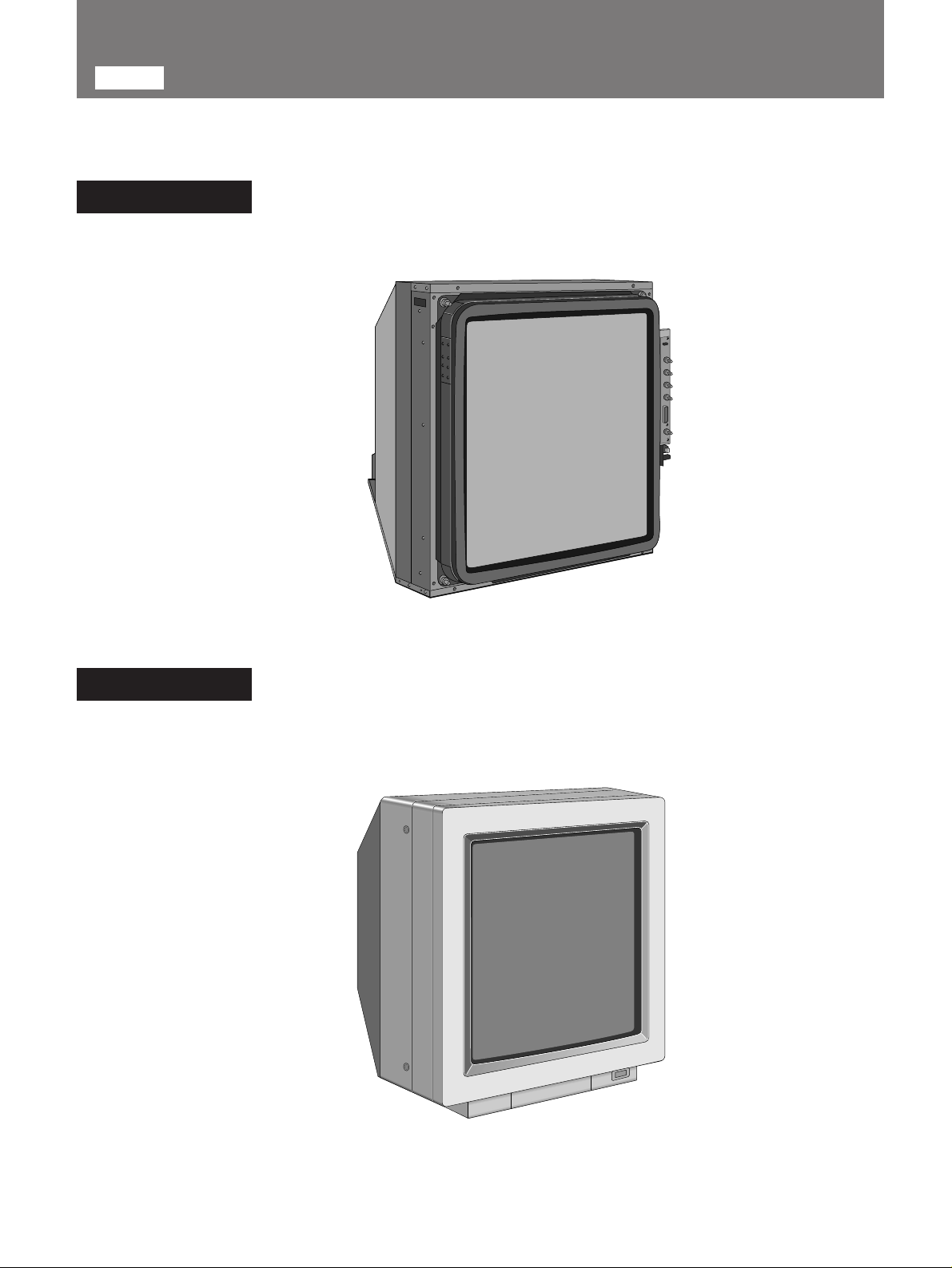
シャーシモデル
DDM-2801CU/DDM-2811CU
外装付きモデル
DDM-2802CU/DDM-2802CNU
2
Page 3
目次
特長
特長 ...........................................................................................
お使いになる前に ....................................................................
安全上のご注意....................................................................
電源電圧 ...............................................................................
各モデルの仕向地 ................................................................
取り扱い上のご注意 ............................................................
各部の名称と働き ....................................................................
前面 .......................................................................................
裏面 .......................................................................................
主な仕様....................................................................................
お使いになる前に
3
3
シリーズは、超高解像度ラスター走査方式のグラ
DDM
フィック用ディスプレイです。
3
3
●超高密度画面
3
3
4
4
300MHz
レームの画素が、
有する、きわめて高密度な画面を実現。きめの細かいグラ
フィック画像が得られます。
におよぶ超高帯域ビデオ回路の開発により、1フ
ドット(横)×
2,048
2,048
6
7
●有効画面20インチ(縦)×20インチ(横)
有効画面の縦横比1:1。32型トリニトロン受像管の採用
により、正方形のブラウン管有効画面を実現しました。
●マルチレイヤーオプチカルコーティングを採用。
外光反射の少ない画面が得られます。
ライン(縦)を
このディスプレイは、一般のテレビ受像機としてはご使用になれません。
安全上のご注意
この装置は、情報処理装置等電波障害自主規制協議会
(
)の基準に基づくクラスA情報技術装置です。この
VCCI
装置を家庭環境で使用すると電波妨害を引き起こすこと
があります。この場合には使用者が適切な対策を講ずる
よう要求されることがあります。
電源電圧
各モデルは
正しい電源電圧でお使いください。
各モデルの仕向地
DDM-2801CU/DDM-2802CU/
感電を防ぐために
DDM-2802CNU
DDM-2811CU
内部には電圧の高い部分があり、手を触れると危険です。
内部の点検が必要なときは、お買い上げいただいた営業窓口
にご相談ください。
異物
内部に燃えやすいものや金属、水などが入ると故障や事故の
原因になります。
衝撃
持ち運びの際は衝撃を与えないように、特にブラウン管(画
面)にはご注意ください。
取り扱い上のご注意
使用・保管場所
長期間ご愛用いただくため、次のような場所での使用および
保管は避けてください。
極端に暑い所や寒い所。
•
(推奨使用温度は+
湿気、ほこりの多い所。
•
激しい振動のある所。
•
強い磁気を発生するものの近く。
•
強力な電波を発生するテレビ、ラジオの送信所の近く。
•
直射日光の当たる所。
•
AC100〜240V
℃〜+30℃)
20
の電源電圧範囲で動作します。
北半球
南半球
3
Page 4
各部の名称と働き
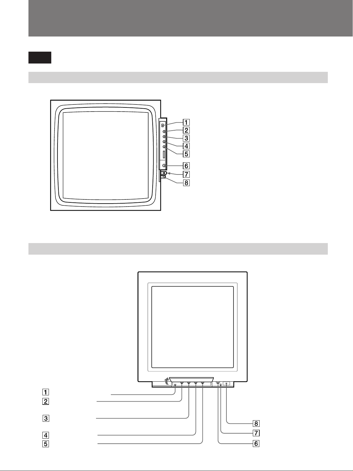
前面
DDM-2801CU/DDM-2811CU
DDM-2802CU/DDM-2802CNU
DEGAUSS
H STAT
V STAT
V CENT
BRIGHT
CONT
電源ランプ
POWER
つまみ
つまみ
つまみ
つまみ
つまみ
スイッチ
スイッチ
4
DEGAUSS
H STAT
V STAT
V CENT
BRIGHT
つまみ
つまみ
つまみ
つまみ
スイッチ
POWER
電源ランプ
CONT
つまみ
スイッチ
Page 5
デガウス
1
DEGAUSS
電源を入れたまま消磁したいとき、このスイッチを1回押
します。再度使用するときは
い。
(消磁)スイッチ
5
分以上間隔をおいてくださ
ブライト
5
BRIGHT
画面の明るさを調整します。通常はセンタークリック位
置で使用します。
(明るさ)つまみ
2
H STAT
画面中心部のコンバージェンス調整に使います。赤と青
の縦線が緑の線に重なるように調整します。
赤い線が右へ、
青い線が左へ動く。
3
V STAT
み
画面中心部のコンバージェンス調整に使います。赤と青
の横線が緑の線に重なるように調整します。
B
G
R
青い線が下へ
赤い線が上へ動く。
4
V CENT
画面の垂直方向のセンター位置を調整します。
(水平スタティックコンバージェンス)つまみ
RGB
(シャーシモデル)
外装付き
モデル
(垂直スタティックコンバージェンス)つま
)(
BGR
赤い線が左へ、
青い線が右へ動く。
R
(シャーシモデル)
G
B
外装付き
モデル
(垂直方向センタリング)つまみ
赤い線が下へ、
青い線が上へ動く。
)(
明るくなる。 暗くなる。
6
7 電源ランプ
(コントラスト)つまみ
CONT
画面のコントラストを調整します。
コントラストが
強くなる。
POWER
パワー
8
POWER
裏面の
MAIN
込むと、画像が現れます。このとき、オートデガウス回
路が作動しますので、約
もう一度押すと画像が消えます。
(シャーシモデル)
外装付き
モデル
(シャーシモデル)
スイッチをONにすると点灯します。
(電源)スイッチ
サーキットブレーカーがONのときに押し
)(
コントラストが
弱くなる。
外装付き
モデル
)(
秒間画像が揺れます。
5
(シャーシモデル)
画像が上へ動く。 画像が下へ動く。
外装付き
モデル
)(
5
Page 6
各部の名称と働き
裏面
R/G/B/
LANDING SENSOR
I/F
MAIN
1
R/G/B
(赤)、G(緑)、B(青)の映像信号の入力端子。内部で
R
50
2
LANDING SENSOR
ランディングセンサー(
ランディング(色むら)を補正するための端子です。
3
I/F
画ひずみ、コンバージェンス、色温度などの調整をする
とき、この
ロールするためのコントローラー(
します。
メイン
4
MAIN
通常、使用するときは、I側を
押し込んでおきます(
入力端子
端子
サーキットブレーカー
入力端子(
Ωに終端されています。
ランディング センサー
BNC
DDM-LS10
端子(
D-sub 15
(インターフェース端子)に外部からコント
I/F
ピン)
サーキットブレーカー
ON
端子
型)
端子(8ピン)
)を接続して、ミス
DDM-RM10
)。
)を接続
入力端子
HD
入力端子
VD
POWER
FAILURE
ROTATION
AC IN
パワー
7
POWER
前面の
フェイラー
8
FAILURE
回路に異常が生じると点灯します。このランプが点灯し
たときは、すぐに
お買い上げいただいた営業窓口にご相談ください。
9
ROTATION
画面の回転を調整します。ドライバーなどを使って回し
てください。
画像が時計回
りに回転する。
0
AC IN
AC
ランプ(緑)
POWER
スイッチをONにすると、点灯します。
ランプ(赤)
サーキットブレーカーを切り、
MAIN
ロテーション
(回転)半固定つまみ
端子
電源コンセントに接続します。
ランプ
ランプ
半固定つまみ
端子
画像が反時計回
りに回転する。
5
6
入力端子(
HD
水平同期信号の入力端子。内部で75Ωに終端されていま
す。
入力端子(
VD
垂直同期信号の入力端子。内部で75Ωに終端されていま
す。
BNC
BNC
型)
型)
6
1、5、6
い。
につなぐ接続ケーブルは二重シールドタイプをご使用くださ
Page 7
主な仕様
システム
有効表示画面
表示可能画素
映像増幅器 周波数帯域
最大輝度
幾可学ひずみ 全画面で、画面の高さの
受像管 高精細度トリニトロンカラー受像管
2114本/60Hz
ター走査方式(水平表示時間
498×498mm(幅/
ドット(横)×
2,048
パルス応答:Tr、Tf共
80cd/m
2
0.31mm
蛍光体
P22
度偏向
90
透過率
69
コンバージェンス
ノンインターレース、ラス
高さ)
ライン(縦)
2,048
60Hzから300MHz
±
以内
3dB
1.6ns
以上
%の半径の円以内
1
蛍光体トリオピッチ
%
5.734µS
以下
C
B
A
A部:0.3mm
B部:0.5mm
C部:0.7mm
以下
以下
以下
)
その他
動作温度
動作湿度
保存温度 −10℃〜60℃
保存湿度
最大外形寸法/質量
型 名
10℃〜40
10%〜95
5%〜95
DDM-2801CU
DDM-2811CU
DDM-2802CU
DDM-2802CNU
付属品 取扱説明書(1)
安全のために(1)
℃
%
%
最大外形寸法(突起部含む)
(幅/高さ/奥行き)
694×673×760mm
×
729×776mm
690
質 量
約
95kg
約
103kg
仕様および外観は改良のため予告なく変更することが
ありますが、ご了承ください。
254mm
457mm
入力
映像信号
外部同期信号
電源
R.G.B
HD、VD
AC100〜240V
50 – 60Hz ±10
消費電力 最大
:
BNC、0.714Vp-p
:
BNC、TTL
負極性(75Ω終端)
、
%
450W (500VA)
、正極性(50Ω終端)
7
Page 8

English
Table of ContentsOwner’ s Record
The model and serial numbers are located at the rear of the
unit. Record these numbers in the spaces provided below.
Refer to them whenever you call upon your dealer regarding
this product.
Model No. Serial No.
WARNING........................................................................... 9
Features ............................................................................ 10
Precautions ....................................................................... 10
Location and Function of Controls .................................... 12
Front panel .................................................................. 12
Rear panel................................................................... 14
Specifications .................................................................... 15
8
Page 9
WARNING
To prevent fire or shock hazard, do not
expose the unit to rain or moisture.
For the customers in the USA
Warning-This equipment has been tested and found to
comply with the limits for a Class A digital device, pursuant
to Part 15 of the FCC Rules. These limits are designed to
provide reasonable protection against harmful interference
when the equipment is operated in a commercial
environment. This equipment generates, uses, and can
radiate radio frequency energy and, if not installed and used
in accordance with the instruction manual, may cause
harmful interference to radio communications. Operation of
this equipment in a residential area is likely to cause harmful
interference in which case the user will be required to
correct the interference at his own expense.
You are cautioned that any changes or modifications not
expressly approved in this manual could void your authority
to operate this equipment.
The shielded interface cable recommended in this manual
must be used with this equipment in order to comply with
the limits for a digital device pursuant to Subpart B of Part
15 of FCC Rules.
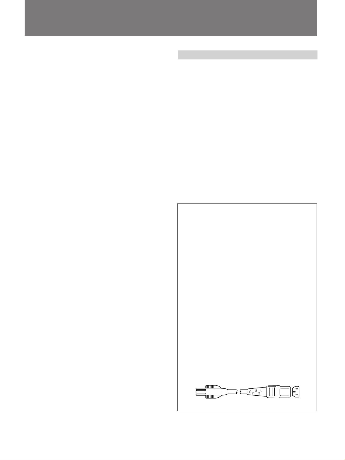
NOTICE
This notice is applicable for USA/Canada only.
If shipped to USA/Canada, install only a UL LISTED/CSA
LABELED power supply cord meeting the following
specifications:
SPECIFICATIONS
Plug Type Nema-Plug 5-15p
Cord Type SVT or SJT, minimum 3 × 18,
AWG
Length Maximum 15 feet
Rating Minimum 7 A, 125 V
NOTICE
Cette notice s’applique aux Etats-Unis et au Canada
uniquement.
Si cet appareil est exporté aux Etats-Unis ou au Canada,
utiliser le cordon d’alimentation portant la mention UL
LISTED/CSA LABELED et remplissant les conditions
suivantes:
SPECIFICATIONS
Type de fiche Fiche Nema 5-15 broches
Cordon Type SVT ou SJT, minimum 3 × 18
AWG
Longueur Maximum 15 pieds
Tension Minimum 7 A, 125 V
9
Page 10

Features Precautions
The DDM series is a super-high-resolution graphic display
monitor which employs a raster scanning method.
Super high density graphic display
An extremely high resolution 2,048 dots (horizontal) × 2,048
lines (vertical) per frame has been made possible through
the development of a 300 MHz band width video amplifier.
20-inch by 20-inch useful screen size
The 32-inch Trinitron picture tube with a 1:1 aspect ratio
presents a square picture.
Multi-layer optical coating
This minimizes ambient light reflection.
This unit will not operate as a normal TV receiver/monitor.
Power requirement
The monitor operates from single phase power, within the
following nominal voltage ranges:
DDM-2801CU/2811CU/2802CU/2802CNU: AC100 - 240V
Destination of each model
DDM-2801CU
DDM-2802CU
DDM-2802CNU
DDM-2811CU
The northern hemisphere
The southern hemisphere
Safety
• Should any liquid or solid object fall into the cabinet,
unplug the unit and have it checked by qualified personnel
before operating it any further.
• Unplug the unit from the wall outlet if it is not to be used
for a long period of time.
Operating Environment
• Temperature: The air temperature in the immediate
surrounding vicinity of an operating monitor, or air
temperature within the structure in which it is operating (for
example within a console), is likely to be greater than the
average ambient room temperature. It is important,
therefore, when installing the monitor, to ensure that the
air temperature in this operating environment of the
monitor does not exceed the maximum allowable
temperature limit of 40 degrees Celsius.
• Air Flow: The level of air flow required for safe operation of
the monitor must not be compromised or reduced in any
way by the condition of its operating environment.
Installation
• Allow adequate air circulation to prevent internal heat
build-up. Do not place the unit on surfaces such as rugs,
blankets or near curtains which might block the ventilation
holes.
• Do not install the unit in a location near heat sources such
as radiators or air ducts, or in a place subject to direct
sunlight, excessive dust, moisture, mechanical vibration,
or shock.
Transportation
• Do not throw away the original carton and packing
materials. They make an ideal container in which to
transport the unit.
When shipping, repack the unit as illustrated on the
carton.
• When carrying, handle with care so as not to expose the
unit to shock, especially to the picture tube.
If you have any questions or problems about this unit,
consult your Sony representative.
10
Page 11

This instruction manual covers the following models.
Chassis model
DDM-2801CU/DDM-2811CU
Bezel and cabinet (B/C) model
DDM-2802CU/DDM-2802CNU
11
Page 12

Location and Function of Controls
Front panel
DDM-2801CU/DDM-2811CU
DEGAUSS switch
H STAT control
V STAT control
V CENT control
BRIGHT control
CONT control
Power indicator
POWER switch
DDM-2802CU/DDM-2802CNU
DEGAUSS switch
H STAT control
V STAT control
POWER switch
12
V CENT control
BRIGHT control
Power indicator
CONT control
Page 13

1 DEGAUSS switch
This switch demagnetizes the screen. Momentarily
press this switch with the power turned on. Wait for 5
minutes or more before activating the switch again.
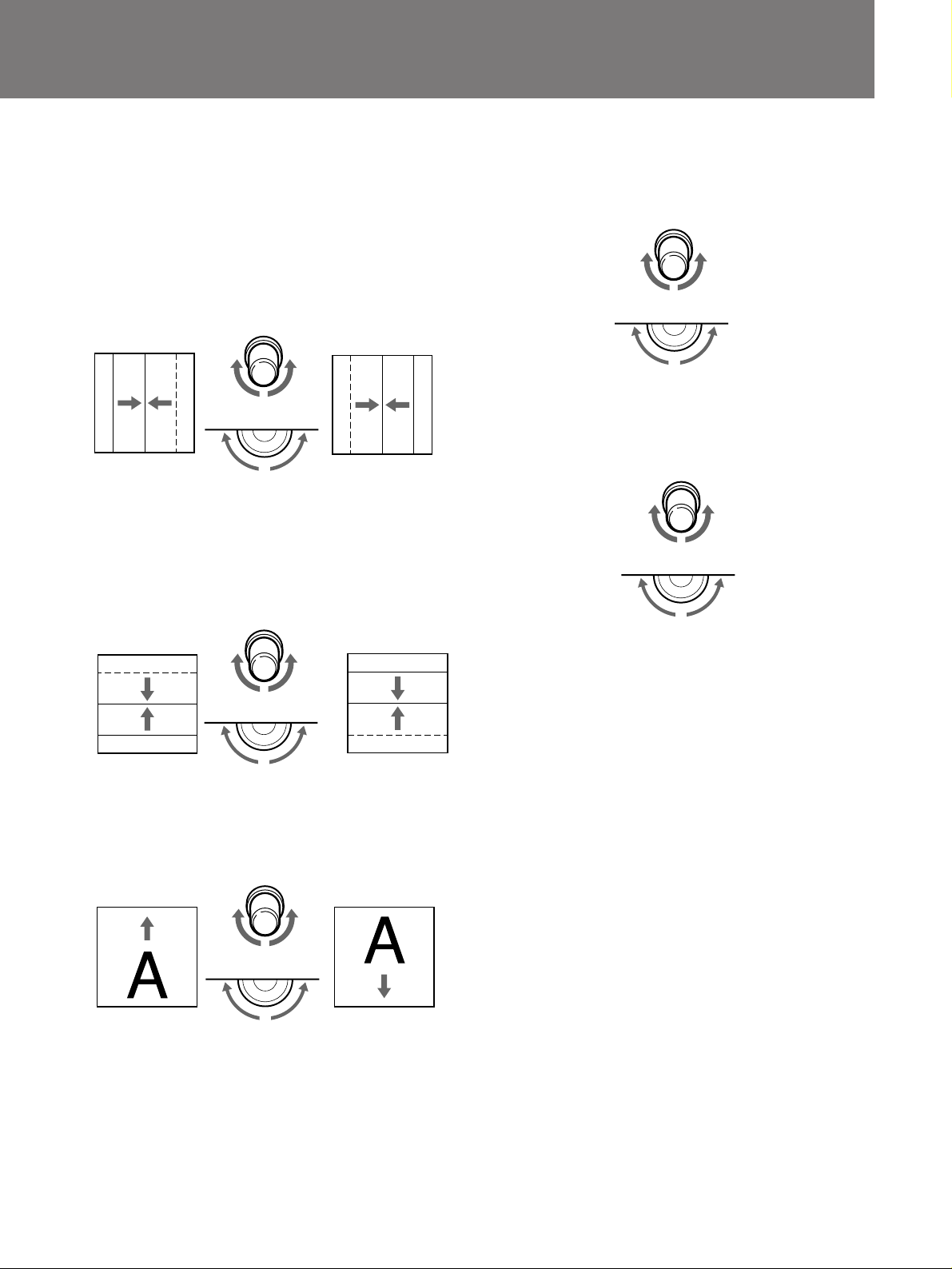
2 H STAT control
This control adjusts the convergence at the center of
the screen, so that the vertical red and blue lines
converge with the green line.
5 BRIGHT control
This control adjusts the picture brightness. Normally set
the control at the center detent position.
For a brighter
picture
(Chassis model)
For a darker
picture
RGB
Move red line to the
right, and blue line to
the left
(Chassis model)
(B/C model)
BGR
Move red line to the
left,and blue line to
the right
3 V STAT control
This control adjusts the convergence at the center of
the screen, so that the horizontal red and blue lines
converge with the green line.
B
G
R
Move red line
upward, and blue line
downward
(Chassis model)
(B/C model)
R
G
B
Move red line
downward, and
blue line upward
4 V CENT control
This control adjusts the vertical position of the picture.
(B/C model)
6 CONT control
This control adjusts the picture contrast.
(Chassis model)
(B/C model)
For less contrastFor more contrast
7 Power indicator
This indicator lights when the POWER switch is turned
on.
8 POWER switch
When the MAIN circuit breaker on the rear panel is
turned on, press the POWER switch to turn on the
display. At this time, automatic degaussing will be
activated causing the picture to shake for about 5
seconds. To turn off the display, press the POWER
switch again.
Move the picture
upward
(Chassis model)
(B/C model)
Move the picture
downward
13
Page 14

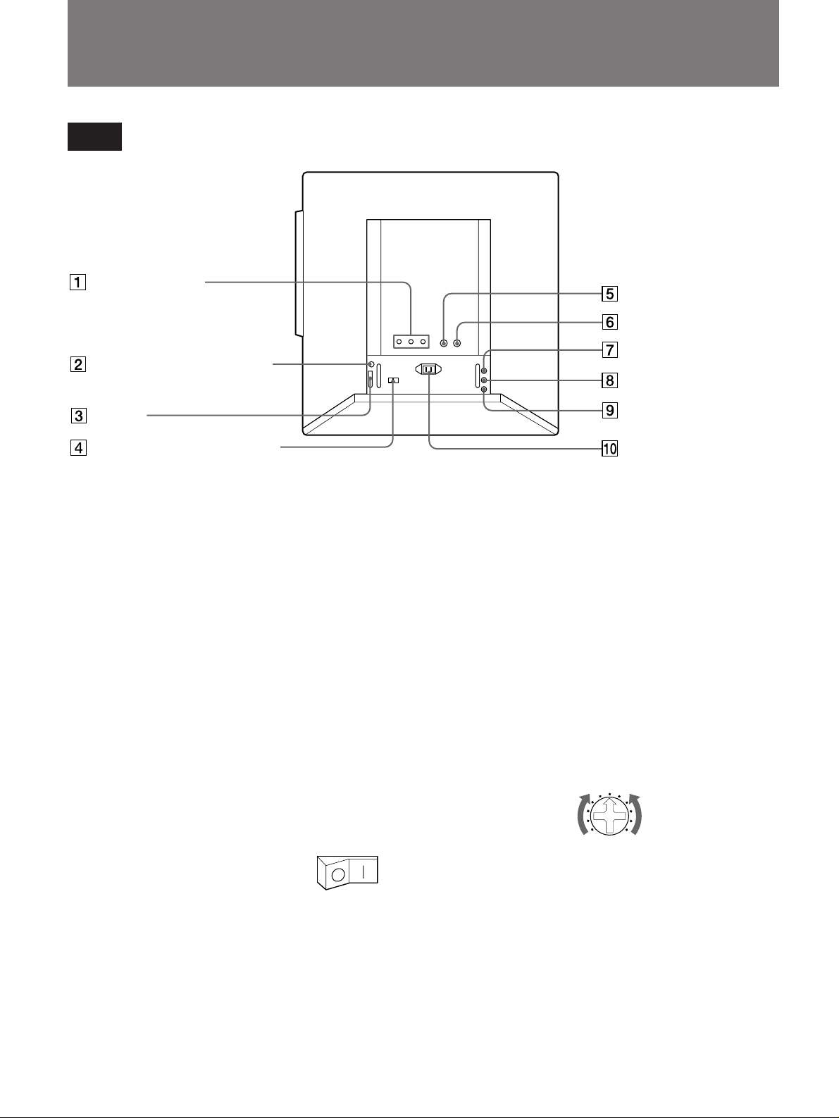
Location and Function of Controls
Rear panel
R/G/B VIDEO IN
connectors
LANDING SENSOR
connector
I/F connector
MAIN circuit breaker
1 R/G/B VIDEO IN connectors (BNC type)
These connectors are used for inputting the R (red), G
(green) and B (blue) signals. The connectors are
terminated at 50 ohms.
2 LANDING SENSOR connector (8 pin)
This connector is used when adjusting uneven color by
connecting the optional landing sensor DDM-LS10.
3 I/F connector (D-sub 15 pin)
This I/F (interface) connector is used when externally
adjusting distortion, convergence, color temperature,
etc. by connecting the optional Remote controller DDMRM10.
4 MAIN circuit breaker
Set this circuit breaker to the I (on)
position when using this unit.
HD input connector
VD input connector
POWER indicator
FAILURE indicator
ROTATION control
AC IN socket
7 POWER indicator (green)
This indicator lights when the POWER switch on the
front panel is turned on.
8 FAILURE indicator (red)
This indicator lights when the circuits inside the unit are
not functioning correctly. Should this lamp light up, turn
off the MAIN circuit breaker and consult Sony
representative.
9 ROTATION CONTROL
This control adjusts the picture rotation. Use a
screwdriver etc. to turn the control.
Rotate the picture
clockwise
Rotate the picture
counterclockwise
5 HD input connector (BNC type)
This connector is used for inputting horizontal drive
pulses (HD). The connector is terminated at 75 ohms.
6 VD input connector (BNC type)
This connector is used for inputting vertical drive pulses
(VD). The connector is terminated at 75 ohms.
14
0 AC IN socket
Connect an AC power cord here.
Note
When connecting to 1, 5 and 6, use a double-shielded coaxial
cable.
Page 15

Specifications
System 2,114 lines, 60 Hz non-interlaced, Raster
Picture size 498 (w) × 498 (h) mm (19.6 × 19.6 inches)
Addressable pixels
Video amplifier Band width; 60 Hz to 300 MHz ±3 dB
Maximum brightness
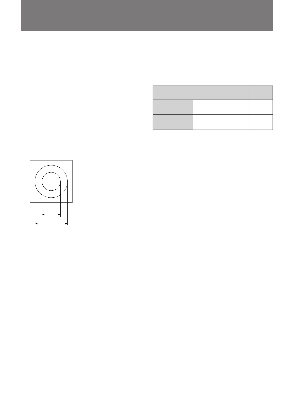
Geometric distortion
Picture tube Super fine-pitch Trinitron color tube
Convergence
scanning system
(Horizontal display time 5.734 µS)
2,048 dots (H) × 2,048 lines (V)
Pulse rise/fall time: 1.6 ns or less
More than 80 cd/m2 (at screen center)
Within the area of a circle whose radius equals
1% of the picture height at all area of the pictrue.
0.31 mm phosphor trio pitch
P22 phosphor
90 degree deflection
69% total optical transmission
Zone A:
Zone B:
Zone C:
≦0.3 mm (0.013 inch)
≦0.5 mm (0.020 inch)
≦0.7 mm (0.030 inch)
C
B
A
Others
Operating temperature
Operating humidity
Storage temperature
Storage humidity
Dimensions and Mass
Model
DDM-2801CU
DDM-2811CU
DDM-2802CU
DDM-2802CNU
Accessaries Operating instructions (1)
Design and specifications are subject to change without notice.
10°C to 40°C (47°F to 104°F)
10% to 95%
–10°C to 60°C (17°F to 140°F)
5% to 95%
Dimensions including
projecting parts (w/h/d)
Approx. 694 × 673 × 760 mm
(273/8 × 261/2 × 30 inches)
Approx. 690 × 729 × 776 mm
(271/4 × 283/4 × 305/8 inches)
Mass
Approx. 95 kg
(210 lb)
Approx. 103 kg
(227 lb)
254 mm
1
/
(10
8 inches)
457 mm
(18 inches)
Inputs
Video inputs R.G.B:
Sync inputs HD, VD:
Power requirements
Power consumption
BNC, 50 ohms terminated
0.714 Vp-p, positive
BNC, 75 ohms terminated
TTL, negative
AC 100 to 240 V, 50 – 60 Hz ±10%
Maximum 450 W (500 VA)
15
Page 16

Français
Table des matièresAvertissement
Afin d’éviter tout risque d’incendie ou d’électrocution, ne pas
exposer cet appareil à la pluie ou à l’humidité.
Afin d’écarter tout risque d’électrocution, garder le coffret
fermé. Ne confier l’entretien de l’appareil qu’à un personnel
qualifié.
Caractéristiques
Les appareils de la série DDM sont des moniteurs à
affichage de donnée couleur de très haute résolution qui
utilisent une méthode de balayage par quadrillage.
Ecran graphique à super haute densité
La définition extrêmement élevée de 2048 points
horizontaux par 2048 lignes verticales par trame est
obtenue grâce au développement d’un ampliticateur vidéo à
bande passante de 300 MHz.
Dimension d’écran utilisable de 20 × 20 pouces
Le tube image Trinitron de 32 pouces au format d’image 1:1
présente une image carrée.
Revêtement optique multicouche
Il diminue les réflexions de la lumière ambiante.
16
Caractéristiques ................................................................ 16
Prècautions ....................................................................... 16
Emplacement et fonction des commandes ....................... 18
Panneau frontal ........................................................... 18
Panneau arrière........................................................... 20
Spécifications .................................................................... 21
Précautions
Cet appareil ne fonctionnera pas comme récepteur/moniteur
de télévision ordinaire.
Puissance de raccordement
Le moniteur fonctionne par alimentation à phase unique,
dans les plages de tension nominale suivantes:
DDM-2801CU/2811CU/2802CU/2802CNU: CA 100 - 240 V.
Destination de chaque modèle
DDM-2801CU
DDM-2802CU
DDM-2802CNU
DDM-2811CU
Sécurité
• Si un solide ou liquide tombait à l’intérieur du coffret,
débrancher l’appareil et le faire vérifier par un réparateur
qualifié avant de le remettre en service.
• Débrancher l’appareil du secteur s’il ne doit pas être utilisé
pendant une période prolongée.
Environnement d’exploitation
• Température: La température de l’air aux alentours
immédiats d’un moniteur allumé, ou la température de l’air
à l’intérieur de la structure dans laquelle il fonctionne
(dans une console par exemple), est susceptible d’être
plus élevée que la température ambiante de la pièce.
C’est pourquoi il est important, lors de l’installation du
moniteur, de veiller à ce que la température de l’air dans
l’environnement d’exploitation du moniteur ne dépasse
pas la limite de température maximale acceptable de
40°C.
• Flux d’air: Le niveau de flux d’air requis pour un
fonctionnement en toute sécurité du moniteur ne doit pas
être remis en question ou réduit quelle que soit la situation
de l’environnement d’exploitation.
Installation
• Prévoir une circulation d’air adéquate pour éviter une
surchauffe à l’intérieur de l’appareil. Ne pas placer
l’appareil sur des surfaces telles que les tapis,
couvertures, ou à proximité de rideaux, qui risqueraient
d’obstruer les fentes d’aération.
• Ne pas placer l’appareil près de sources de chaleur telles
radiateurs ou conduits d’aération, ou dans des endroits
soumis au rayonnement solaire direct, à la poussière ou
l’humidité excessives, des vibrations mécaniques ou des
chocs.
Transport
• Ne pas jeter le carton et les matériaux d’emballage. Ils
seront très utiles pour déplacer l’appareil. Lors du
transport de l’appareil, le remballer comme illustré sur le
carton.
• Lors de son transport, procéder avec précaution pour
éviter d’exposer l’appareil, et surtout le tube image, à des
chocs.
Pour toute question ou en cas de problèmes relatifs à cet
appareil, s’adresser à un représentant Sony.
Hémisphère Nord
Hémisphère Sud
Page 17

Ce mode d’emploi couvre les modèles suivants.
Modèle châssis
DDM-2801CU/DDM-2811CU
Modèle Bezel et coffret (B/C)
DDM-2802CU/DDM-2802CNU
17
Page 18

Emplacement et fonction des commandes
Panneau frontal
DDM-2801CU/DDM-2811CU
Commutateur DEGAUSS
Réglage H STAT
Réglage V STAT
Réglage V CENT
Réglage BRIGHT
Réglage CONT
Témoin d’alimentation
Interrupteur POWER
DDM-2802CU/DDM-2802CNU
Commutateur DEGAUSS
Réglage H STAT
Réglage V STAT
Réglage V CENT
Réglage BRIGHT
Interrupteur POWER
Témoin d’alimentation
Réglage CONT
18
Page 19

1 Commutateur DEGAUSS
Pour démagnétiser l’écran, appuyer momentanément
sur ce commutateur lorsque l’appareil est sous tension.
Attendre 5 minutes ou plus avant d’activer de
nouveau le commutateur.
2 Réglage H STAT
Régler la convergence au centre de l’écran de façon
que les lignes verticales rouge et bleue convergent sur
la ligne verte.
5 Réglage BRIGHT
Sert à régler la luminosité de l’image. Normalement, le
laisser sur la position de butée centrale.
pour une image
plus claire
(Modèle châssis)
pour une image
plus sombre
RGB
La ligne rouge à
droite, et la ligne
bleue à gauche
(Modèle châssis)
(Modèle B/C)
BGR
La ligne rouge à
gauche, et la ligne
bleue à droite
3 Réglage V STAT
Régler la convergence au centre de l’écran de façon
que les lignes horizontales rouge et bleue convergent
sur la ligne verte.
B
G
R
La ligne rouge en
haut, en la ligne
bleue en bas
(Modèle châssis)
(Modèle B/C)
R
G
B
La ligne rouge en
bas, et la ligne
bleue en haut
(Modèle B/C)
6 Réglage CONT
Sert à régler le contraste de l’image.
pour augmenter
le contraste
(Modèle châssis)
(Modèle B/C)
pour diminuer
le contraste
7 Témoin d’alimentation
S’allume lorsque l’appareil est sous tension.
8 Interrupteur POWER
Lorsque le disjoncteur principal MAIN du panneau
arrière est enclenché, appuyer sur l’interrupteur
POWER pour allumer la console de visualisation. A ce
moment, la démagnétisation automatique sera activée
et l’image va trembler pendant environ 5 secondes.
Pour éteindre la console de visualisation, appuyer de
nouveau sur l’interrupteur POWER.
4 Réglage V CENT
Sert à régler la position verticable de l’image.
(Modèle châssis)
Pour déplacer
l’image vers le
haut
(Modèle B/C)
Pour déplacer
l’image vers le bas
19
Page 20

Emplacement et fonction des commandes
Panneau arrière
Connecteurs R/G/B
VIDEO IN
Connecteur LANDING
SENSOR
Connecteur I/F
Disjoncteur MAIN
1 Connecteurs R/G/B VIDEO IN (type BNC)
Servent à entrer les signaux rouges (R), verts (G) et
bleus (B). La borne des connecteurs est de 50 ohms.
2 Connecteur LANDING SENSOR (8 broches)
Ce connecteur s’emploie lors du réglage de couleurs
inégales par raccordement du capteur d’orientation
cardinale, le DDM-LS10, disponible en option.
3 Connecteur I/F (D-sub à 15 broches)
Ce connecteur I/F (interface) est utilisé pour ajuster la
distorsion, la convergence, la température de couleur,
etc, de l’extérieur en raccordant la télécommande,
DDM-RM10, disponible en option.
4 Disjoncteur MAIN
Laisser ce disjoncteur enfoncé du
côté I (en service) pendant
l’utilisation de cet appareil.
5 Connecteur d’entrée HD (type BNC)
Sert à entrer les impulsions d’entraînement horizontal.
La borne du connecteur est de 75 ohms.
6 Connecteur d’entrée VD (type BNC)
Sert à entrer les impulsions d’entraînement vertical. La
borne du connecteur est de 75 ohms.
Connecteur d’entrée HD
Connecteur d’entrée VD
Témoin POWER
Témoin FAILURE
Réglage ROTATION
Prise AC IN
7 Témoin POWER (vert)
S’allume lorsque l’interrupteur d’alimentation (POWER)
du panneau frontal est allumé.
8 Témoin FAILURE (rouge)
S’allume lorsque les circuits à l’intérieur de l’appareil ne
fonctionnent pas correctement.
Si ce témoin venait à s’allumer, désactiver le disjoncteur
MAIN et consulter le représentant Sony.
9 Réglage ROTATION
Sert à régler la rotation de l’image. Utipiser un
tournevis, ou autre, pour tourner la commande.
Faites pivoter
l’image dans le
sens horaire.
Faites pivoter
l’image dans le
sens antihoraire.
0 Prise AC IN
Raccorder le cordon d’alimentation secteur à cette
prise.
Remarque
Lors du raccordement à 1, 5, et 6, utiliser un cable coxial à
double blindage.
20
Page 21

Spécifications
Système 2114 lignes, 60 Hz non entrelacé, système de
Dimensions de l’image
Pixels adressables
Amplificateur vidèo
Luminosité maximale
Distorsion géométrique
Tube image Tube couleur Trinitron à pas de quadrillage super
Convergence
balayage par quadrillage
(Temps d’affichage horizontal 5,734 µs)
498 (l) × 498 (h) mm (19,6 × 19,6 pouces)
2.048 points (H) × 2.048 lignes (V)
Largeur passante: 60 Hz – 300 MHz ±3 dB
Temps de montée/descente de l’impulsion:
1,6 ns ou moins
Plus de 80 cd/m2 (au centre de l’écran)
Dans la zone d’un cercle dont le diamètre est égal
à 1% de la hauteur de l’image recouvrant foute la
zone de l’image.
fin
Pas de 0,31 mm par paquet de trois
luminophores
Luminophore P22
Déflexion de 90 degrés
Transmission optique totale de 69%
Zone A:
Zone B:
Zone C:
≦ 0,3 mm (0,013 pouce)
≦ 0,5 mm (0,020 pouce)
≦ 0,7 mm (0,030 pouce)
Autres spécifications
Température d’utilisation
Humidité ambiante
Température de stockage
Humidité de stockage
Dimensions et poids
Pour les
modèles
DDM-2801CU
DDM-2811CU
DDM-2802CU
DDM-2802CNU
Accessoire Mode d’emploi (1)
La conception et les spécifications sont modifiables sans préavis.
10°C à 40°C (47°F à 104°F)
10% à 95%
–10°C à 60°C (17°F à 140°F)
5% à 95%
Dimensions hors tout
(l/h/p)
Env. 694 × 673 × 760 mm
(273/8 × 261/2 × 30 pouces)
Env. 690 × 729 × 776 mm
(271/4 × 283/4 × 305/8 pouces)
Poids
Env. 95 kg
(210 livres)
Env. 103 kg
(227 livres)
C
B
A
254 mm
1
/
8 po.)
(10
457 mm
(18 po.)
Entrées
Entrées vidéo R.G.B:
BNC à borne de 50 ohms
Entrées de synchronisation
Puissances de raccordement
Consommation Maxi. 450 W (500 VA)
0,714 Vc-c, positive
HD, VD:
BNC à borne de 75 ohrns
TTL, négative
100 à 240 V CA, 50 – 60 Hz ±10%
21
Page 22

Deutsch
InhaltsverzeichnisVorsicht
Um Feuergefahr und die Gefahr eines elektrischen
Schlages zu vermeiden, darf das Gerät weder Regen noch
Feuchtigkeit ausgesetzt werden.
Um einen elektrischen Schlag zu vermeiden, darf das
Gehäuse nicht geöffnet werden. Überlassen Sie
Wartungsarbeiten stets nur einem Fachmann.
Dieses Gerät ist nur für den Gebrauch in Gewerbe und
Leichtindustrie bestimmt. Es entspricht der Klasse A, es
erfüllt nicht die Grenwerte der Klasse B. In Deutschland
muß der Erwerber eine spezielle Betriebserlaubnis bei der
zuständigen Außenstelle des BAPT-beantragen, um dieses
Gerät betreiben zu dürfen.
EN55022/1987 Klasse A
EN50082-1/1992
EN60555-2/1987
Achtung bei der Netzverbindung
• Verwenden Sie das mitgelieferte Netzkabel.
für 220 bis 240 V Wechselstrom
• Warten Sie nach dem Ausschalten des Geräts mindestens
30 Sekunden, bevor Sie das Netzkabel lösen. In dieser
Zeit kann sich die statische Elektrizität auf der Oberfläche
der Kathodenstrahlröhre entladen.
• Nach dem Einschalten wird die Kathodenstrahlröhre für
ca. 5 Sekunden entmagnetisiert. Dadurch wird ein starkes
magnetisches Feld um den Metallrand der Röhre erzeugt,
das Daten auf Magnetbändern oder Disketten, die sich in
der Nähe befinden, beschädigen könnte. Bitte plazieren
Sie daher keine magnetischen Aufzeichnugsgeräte und
Bänder/Disketten in unmittelbarer Nähe.
Besondere Merkmale
Der Grafikmonitor DDM mit Rasterabtastung zeichnet sich
durch eine äußerst hohe Auflösung aus.
Hochauflösende graphische Darstellung
Dank des Videoverstärkers mit einer Bandbreite von 300
MHz erreicht der Monitor eine extrem hohe Auflösung von
2.048 Punkten (horizontal) × 2.048 Linien (vertikal) pro
Vollbild.
Nutzbare Bildschirmgröße von 20 × 20 Zoll
Die 32-Zoll-Trinitron-Bildröhre liefert ein quadratisches Bild
mit einem Bildseitenverhältnis von 1:1.
Mehrlagige optische Beschichtung
Reflexionen von Umgebungslicht werden minimiert.
22
Besondere Merkmale ........................................................ 22
Zur besonderen Beachtung .............................................. 22
Lage und Funktion der Bedienungselemente ................... 24
Vorderseite .................................................................. 24
Rückseite..................................................................... 26
Technische Daten ............................................................. 27
Zur besonderen
Beachtung
Dieses Gerät kann nicht als normales TV-Gerät/Monitor
verwendet werden.
Betriebsspannung
Der Monitor arbeitet mit einer Einphasenstromversorgung,
und zwar innerhalb der folgenden Nennspannungsbereiche:
DDM-2801CU/2811CU/2802CU/2802CNU: 100 - 240 V
Wechselstrom.
Bestimmungsgebiet der einzelnen Modelle
DDM-2801CU
DDM-2802CU
DDM-2802CNU
DDM-2811CU
Zur Sicherheit
• Sollte Flüssigkeit oder ein fester Gegenstand in das
Geräteinnere gelangen, trennen Sie das Gerät vom Netz,
und lassen Sie es von einem Fachmann überprüfen, bevor
Sie es weiterverwenden.
• Bei längerer Nichtverwendung des Gerätes trennen Sie es
von der Wandsteckdose ab.
Betriebsumgebung
• Temparatur : Die Lufttemparatur in unmittelbarer Nähe
eines Monitors im Betriebszustand, oder die
Lufttemperatur innerhalb eines Gebildes, in dem er
betrieben wird (z.B. in einer Konsole), wird wahrscheinlich
höher sein als die durchschnittliche Zimmertemparatur
seiner Umgebung. Es ist daher wichtig bei der Installation
des Monitors sicherzustellen, daß die Lufttemparatur in
der Betriebsumgebung des Monitors nicht die maximal
erlaubte Temperatur von 40 Grad Celsius Überschreitet.
• Luftzirkulation : Das Niveau der benötigten Luftzirkulation
zum sicheren Betrieb eines Monitors, darf nicht durch
Bedingungen oder Verhältnisse seiner Betriebsumgebung
beeinträchtigt oder reduziert werden.
Zur Aufstellung
• Achten Sie auf ausreichende Luftzirkulation, um einen
internen Hitzestau zu vermeiden. Stellen Sie das Gerät
nicht auf weichen Unterlagen (Teppichen, Decken usw.)
und auch nicht in der Nähe von Wandbehängen Gardinen
usw. auf, da sonst die Ventilationsöffnungen blockiert
werden können.
• Stellen Sie das Gerät nicht in der Nähe von Wärmequellen
wie Heizungen und Warmluftauslässen auf, und schützen
Sie es vor direktem Sonnenlicht, übermäßigem Staub,
Feuchtigkeit, Vibrationen und Stößen.
Zum Transport
• Werfen Sie den Karton und das Verpackungsmaterial
nicht weg. Sie sind ideal für den Transport des Monitors
geeignet. Wenn Sie das Gerät transportieren müssen,
verpacken Sie es, wie auf dem Karton abgebildet.
• Achten Sie bei einem Transport unbedingt darauf, daß der
Monitor, besonders die Bildröhre, keinen Stößen
ausgesetzt wird.
Bei weiterführenden Fragen und Problemen bezüglich
dieses Gerätes wenden Sie sich an Ihre SonyNiederlassung.
Nördliche Hemisphäre
Südliche Hemisphäre
Page 23

Diese Bedienungsanleitung behandelt die folgenden Modelle.
Chassis-Modell
DDM-2801CU/DDM-2811CU
Einbau- und Gehäuse-Modell (B/C)-Modell
DDM-2802CU/DDM-2802CNU
23
Page 24

Lage und Funktion der Bedienungselemente
Vorderseite
DDM-2801CU/DDM-2811CU
Entmagnetisierungsschalter (DEGAUSS)
Horizontal-Konvergenzregler (H STAT)
Vertikal-Konvergenzregler (V STAT)
Vertikal-Zentrierregler (V CENT)
Helligkeitsregler (BRIGHT)
Kontrastregler (CONT)
Einschalt-Anzeige
Netzschalter (POWER)
DDM-2802CU/DDM-2802CNU
Entmagnetisierungsschalter (DEGAUSS)
Horizontal-Konvergenzregler
(H STAT)
Vertikal-Konvergenzregler
(V STAT)
Vertikal-Zentrierregler (V CENT)
Helligkeitsregler (BRIGHT)
Netzschalter (POWER)
Einschalt-Anzeige
Kontrastregler (CONT)
24
Page 25

1 Entmagnetisierungsschalter (DEGAUSS)
Zum Entmagnetisieren des Bildschirms: Diesen
Schalter bei eingeschaltetem Gerät kurz drücken, dann
mindestens fünf Minuten warten und ernuet drücken.
2 Horizontal-Konvergenzregler (H STAT)
Die Konvergenzeinstellung ist so vorzunehmen, daß die
vertikale rote und blaue Linie in der Bildschimmitte mit
der grünen Linie zusammenfällt.
5 Helligkeitsregler (BRIGHT)
Zur Einstellung der Bildhelligkeit. Normalerweise sollte
dieser Regler in der einrastenden Mittelposition stehen.
für helleres Bild für dunkleres Bild
(Chassis-Modell)
RGB
zum Verschieben der
roten Linie nach
rechts und der
blauen Linie nach
links
(Chassis-Modell)
(B/C-Modell)
BGR
zum Verschieben der
roten Linie nach links
und der blauen Linie
nach links
3 Vertikal-Konvergenzregler (V STAT)
Die Konvergenzeinstellung ist so vorzunehmen, daß die
horizontale rote und blaue Linie in der Bildschirmmitte
mit der grünen Linie zusammenfällt.
B
G
R
zum Varschieben der
roten Linie nach oben
und der blauen Linie
nach unten
(Chassis-Modell)
(B/C-Modell)
R
G
B
zum Verschieben der
roten Linie nach
unten und der blauen
Linie nach oben
(B/C-Modell)
6 Kontrastregler (CONT)
Zur Einstellung des Bildkontrastes
für höheren
Kontrast
(Chassis-Modell)
(B/C-Modell)
für geringeren
Kontrast
7 Einschalt-Anzeige
Leuchtet bei eingeschaltetem POWER-Schalter auf.
8 Netzschalter (POWER)
Wenn der MAIN-Schalter an der Rückseite
eingeschaltet ist, kann das Gerät am POWER-Schalter
ein- und ausgeschaltet werden. Beim Einschalten wird
automatisch eine Entmagnetisierung ausgeführt, wobei
das Bild ca. fünf Sekunden lang zittert.
4 Vertikal-Zentrierregler (V CENT)
Zur Einjustierung der vertikalen Bildposition
(Chassis-Modell)
zum Verschieben
nach oben
(B/C-Modell)
zum Verschieben
nach unten
25
Page 26

Lage und Funktion der Bedienungselemente
Rückseite
R/G/B-Videoeingänge
(R/G/B VIDEO IN)
Buchse für Strahlauswertungssensor
(LANDING SENSOR)
Fernsteuerbuchse (I/F)
Hauptsicherungsschalter (MAIN)
1 R/G/B-Videoeingänge (R/G/B VIDEO IN)
(BNC-Buchse)
Zur Zuleitung der Rot-, Grün- und Blau-Signale. Die
Buchsen besitzen eine Impedanz von 50 Ohm.
2 Buchse für Strahlauswertungssensor
(LANDING SENSOR) (8pol)
Zur Einjustierung einer gleichmäßigen Farbverteilung
kann hier ein Strahlauswertungssensor DDM-LS10
angeschlossen werden.
HorizontalansteuerungsEingang (HD)
VertikalansteuerungsEingang (VD)
Einschalt-Anzeige (POWER)
Fehler-Anzeige (FAILURE)
Rotationsregler (ROTATION)
Netzanschluß (AC IN)
7 Einschalt-Anzeige (POWER) (grün)
Leuchtet, wenn der POWER-Schalter an der
Vorderseite eingeschaltet ist.
8 Fehler-Anzeige (FAILURE) (rot)
Leuchtet bei einer Störung der internen Schaltkreise.
Wenn diese Anzeige leuchtet, schalten Sie den
Trennschalter MAIN aus, und wenden Sie sich an Ihren
Sony-Kundendienst.
3 Fernsteuerbuchse (I/F) (D-Sub 15pol)
Zum Anschluß der getrennt erhältlichen Steuereinheit
DDM-RM10, die eine Einstellung von Bildgeometrie,
Konvergenz, Farbtemperatur usw, ermöglicht.
4 Hauptsicherungsschalter (MAIN)
Lassen Sie den Schalter während
der Verwendung dieses Gerätes in
der gedrückten (I) Position.
5 Horizontalansteuerungs-Eingang (HD)
(BNC-Buchse)
Zur Zuleitung des Horizontalansteuerimpulses. Der
Eingang besitzt eine Impedanz von 75 Ohm.
6 Vertikalansteuerungs-Eingang (VD)
(BNC-Buchse)
Zur Zuleitung des Vertikalansteuerimpulses. Der
Eingang besitzt eine Impedanz von 75 Ohm.
26
9 Rotationsregler (ROTATION)
Zum Einstellen der Bildrotation. Drehen Sie den Regler
mit einem Schraubenzieher o.ä.
Drehen des
Bildes im
Uhrzeigersinn
Drehen des Bildes
gegen den
Uhrzeigersinn
0 Netzanschluß (AC IN)
Zum Anschluß des Netzkabels.
Hinweis
Zum Anschluß an die Buchsen 1, 5, und 6, sollte doppelt
abgeschirmtes Koaxialkabel verwendet werden.
Page 27

Technische Daten
Auflösung und Abtastsystem
Bildgröße 498 × 498 mm (B/H)
Adressierbare Punkte
Videoverstärker Bandbreite: 60 Hz bis 300 MHz ±3 dB
Max. Helligkeit über 80 cd/m2 (im Bildschirmzentral)
Geometrische Verzeichnungen
Bildröhre Super-feinzeichnende Trinitron-Farbbildröhre,
Konvergenz
2.114 Zeilen, 60 Hz ohne Zeilensprung,
Rasterabtastung (horizontale Zeilendauer
5,734 µs)
2.048 horizontal × 2.048 vertikal
Anstiegs-/Abfallzeit: 1,6ns oder weniger
Über den ganzen Bildschirm sind die
geometrischen Verzeichnungen kleiner als ein
Kreis, dessen Radius 1% der Bildschirmhöhe
entspricht
0,31 mm Phosphor-Triostreifen. Phosphor P22,
Ablenkung 90°, optische Durchlässigkeit
insgesamt 69%
Zone A:
Zone B:
Zone C:
≦0,3 mm
≦0,5 mm
≦0,7 mm
C
B
A
Weitere Daten
Betriebstemperatur
Betriebsfeuchtigkeit
Lagertemperatur
Lagerfeuchtigkeit
Abmessungen und Gewicht
Modell
DDM-2801CU
DDM-2811CU
DDM-2802CU
DDM-2802CNU
Zubehör Bedienungsanleitung (1)
Änderungen, die dem technischen Fortschritt dienen, bleiben
vorbehalten.
10°C bis 40°C
10% bis 95%
–10°C bis 60°C
5% bis 95%
Abmessungen einschließlich
vorspringender Teile (B/H/T)
ca. 694 × 673 × 760 mm
ca. 690 × 729 × 776 mm
Gewicht
ca.
95 kg
ca.
103 kg
254 mm
457 mm
Eingänge
Videoeingänge
Synchroneingang
Stromversorgung
Leistungsaufnahme
R, G, B:
BNC, Impedanz 50 Ohm, Spannung 0,714
Vss, Video positiv
HD, VD:
BNC, Impedanz 75 Ohm, TTL, negativ
100 - 240 V Wechselstrom,
50 - 60 Hz ±10%
Max. 450 W (500 VA)
27
Page 28

Printed in Japan
 Loading...