

Sony GV-D200, D200E, D800, D800E Service manual
GV-D200/D200E/D800/D800E
SERVICE MANUAL
Ver 1.0 2000. 09
Photo : GV-D800E
NTSC MODEL : GV-D200/D800
PAL MODEL : GV-D200E/D800E
Function difference table
Model
Function
LCD
GV-D200/200E
—
VCR
System
Video recording system
2 rotary heads
Helical scanning system
Audio recording system
Rotary heads, PCM system
Quantization: 12 bits (Fs 32 kHz,
stereo 1, stereo 2), 16 bits (Fs 48 kHz,
stereo)
Video signal
GV-D200/D800:
NTSC color, EIA standards
GV-D200E/D800E:
PAL colour, CCIR standards
Recommended cassette
Hi8
Recording/playback time
(GV-D200/D800: using
120 min. Hi8 video cassette)
(GV-D200E/D800E: using
90 min. Hi8 (PAL) video cassette)
SP mode: 1 hour
LP mode: 1 hour and 30 minutes
Fastforward/rewind time
(GV-D200/D800: using
120 min. Hi8 video cassette)
(GV-D200E/D800E: using
90 min. Hi8 (PAL) video cassette)
Approx. 5 minutes and 15 seconds
/Digital8 video cassette
GV-D800/D800E
4.0 inches
SPECIFICATIONS
Input/output
connectors
S video input
4-pin mini DIN
Luminance signal: 1 Vp-p, 75 ohms,
unbalanced
GV-D200/D800:
Chrominance signal: 0.286 Vp-p
GV-D200E/D800E:
Chrominance signal: 0.3 Vp-p,
75 ohms, unbalanced
S video output
4-pin mini DIN
Luminance signal: 1 Vp-p, 75 ohms,
unbalanced
GV-D200/D800:
Chrominance signal: 0.286 Vp-p
GV-D200E/D800E:
Chrominance signal: 0.3 Vp-p,
75 ohms, unbalanced
Audio/Video input
AV MINIJACK
Video: 1 Vp-p, 75 ohms, unbalanced,
sync negative
Audio: 327 mV, input impedance
more than 47 kiloohms
Video output
Phono jack, 1 Vp-p, 75 ohms,
unbalanced, sync negative
Audio output
Phono jacks (2) 327 mV, output
impedance less than 1 kiloohm
RFU DC OUT
Special minijack DC 5 V
DV input/output
4-pin connector
Headphone jack
Stereo minijack (ø 3.5 mm)
LANC
Stereo mini-minijack (ø 2.5 mm)
LCD screen (GV-D800/D800E)
Picture
4.0 type
80.6 × 60.5 mm (3 1/4 × 2 1/2 in.)
Total dot number
123,200 (560 × 220)
General
Power requirements
7.2 V (battery pack)
8.4 V (AC power adaptor)
Average power consumption
(when using the battery pack)
GV-D800/D800E only
During playback using LCD
4.9 W
During playing back when you close
the LCD panel
3.0 W
Operating temperature
0 °C to 40 °C (32 °F to 104 °F)
Storage temperature
–20 °C to +60 °C (–4 °F to +140 °F)
jack
US Model
Canadian Model
GV-D200/D800
AEP Model
UK Model
E Model
GV-D200E/D800E
B MECHANISM
For MECHANISM ADJUSTMENT, refer to
the “8mm Video MECHANICAL
ADJUSTMENT MANUAL
Dimensions (Approx.)
GV-D200/D200E:
148 × 50 × 135 mm
(5 7/8 × 2 × 5 3/8 in.)
GV-D800/D800E:
148 × 65 × 135 mm
(5 7/8 × 2 5/8 × 5 3/8 in.) (w/h/d)
Mass (approx.)
GV-D200/D200E:
660 g (1 lb 7 oz)
GV-D800/D800E:
930 g (2 lb)
excluding the battery pack and
cassette
Supplied accessories
See page 2.
AC power adaptor
Power requirements
100 - 240 V AC, 50/60 Hz
Power consumption
23 W
Output voltage
DC OUT: 8.4 V, 1.5 A in the
operating mode
Operating temperature
0 °C to 40 °C (32 °F to 104 °F)
Storage temperature
–20 °C to +60 °C (–4 °F to +140 °F)
” (9-973-801-11).
— Continued on next page —
DIGITAL VIDEO CASSETTE RECORDER

Dimensions (approx.)
125 × 39 × 62 mm
(5 × 1 9/16 × 2 1/2 in.) (w/h/d)
excluding projecting parts
Mass (approx.)
280 g (9.8 oz) excluding power cord
Cord length (approx.)
Power cord: 2 m (6.6 feet)
Connecting cord: 1.6 m (5.2 feet)
Design and specifications are subject
to change without notice.
• SUPPLIED ACCESSORIES
Make sure that the following accessories are supplied with your VCR.
21
43
SAFETY-RELATED COMPONENT WARNING!!
COMPONENTS IDENTIFIED BY MARK 0 OR DOTTED LINE WITH
MARK 0 ON THE SCHEMATIC DIAGRAMS AND IN THE PARTS
LIST ARE CRITICAL TO SAFE OPERATION. REPLACE THESE
COMPONENTS WITH SONY PARTS WHOSE PART NUMBERS
APPEAR AS SHOWN IN THIS MANUAL OR IN SUPPLEMENTS
PUBLISHED BY SONY.
1 AC-L10A/L10B/L10C AC power adaptor (1),
Mains lead (1)
23A/V converting cable (1)
ATTENTION AU COMPOSANT AYANT RAPPORT
LES COMPOSANTS IDENTIFÉS P AR UNE MARQUE 0 SUR LES
DIAGRAMMES SCHÉMA TIQUES ET LA LISTE DES PIÈCES SONT
CRITIQUES POUR LA SÉCURITÉ DE FONCTIONNEMENT. NE
REMPLACER CES COMPOSANTS QUE PAR DES PIÈSES SONY
DONT LES NUMÉROS SONT DONNÉS DANS CE MANUEL OU
DANS LES SUPPÉMENTS PUBLIÉS PAR SONY.
À LA SÉCURITÉ!
A/V connecting cable (1)
4 21-pin adaptor (1)
GV-D200E/D800E only
SAFETY CHECK-OUT
After correcting the original service problem, perform the following
safety checks before releasing the set to the customer.
1. Check the area of your repair for unsoldered or poorly-soldered
connections. Check the entire board surface for solder splashes
and bridges.
2. Check the interboard wiring to ensure that no wires are
"pinched" or contact high-wattage resistors.
3. Look for unauthorized replacement parts, particularly
transistors, that were installed during a previous repair . Point
them out to the customer and recommend their replacement.
4. Look for parts which, through functioning, show obvious signs
of deterioration. Point them out to the customer and
recommend their replacement.
5. Check the B+ voltage to see it is at the values specified.
6. Flexible Circuit Board Repairing
• Keep the temperature of the soldering iron around 270˚C
during repairing.
• Do not touch the soldering iron on the same conductor of the
circuit board (within 3 times).
• Be careful not to apply force on the conductor when soldering
or unsoldering.
— 2 —

TABLE OF CONTENTS
SERVICE NOTE
1. POWER SUPPLY DURING REPAIRS ····························· 6
2. TO TAKE OUT A CASSETTE WHEN NOT EJECT
(FORCE EJECT) (1) ·························································· 6
3. TO TAKE OUT A CASSETTE WHEN NOT EJECT
(FORCE EJECT) (2)
(TO TAKE OUT A CASSETTE WITHOUT
HURTING THE TAPE) ······················································ 7
SELF-DIAGNOSIS FUNCTION
1. SELF-DIAGNOSIS FUNCTION······································· 8
2. SELF-DIAGNOSIS DISPLAY ·········································· 8
3. SERVICE MODE DISPLAY ············································· 8
3-1. Display Method ·································································· 8
3-2. Switching of Backup No. ··················································· 8
3-3. End of Display····································································8
4. SELF-DIAGNOSIS CODE TABLE ···································9
2-4. PD-130, LS-56 BOARDS (D800, D800E MODEL) ······2-4
2-5. LCD WINDOW CABINET ASSEMBLY (SP-901, 902)
(D800, D800E MODEL) ·················································2-5
2-6. BATTERY PANEL ASSEMBLY, BATTERY TERMINAL
BOARD, DC-IN CONNECTOR·····································2-6
2-7. VC-250, FU-145 BOARDS·············································2-6
2-8.
CONTROL SWITCH BLOCK (FK-78), LOADING LID ··
2-9. MECHANISM DECK, MAIN FRAME ASSEMBLY ···2-7
2-10. CABINET (R) BLOCK ASSEMBLY, JACK FRAME
(IO-68, IR-38 BOARDS) ················································2-8
2-11. EX-36 BOARD, FP-570 FLEXIBLE BOARD···············2-9
2-12. UPPER CABINET ASSEMBLY,
LCD BLOCK ASSEMBLY (D800, D800E MODEL)····2-9
2-13. HINGE UNIT, FP-569 FLEXIBLE BOARD
(D800, D800E MODEL) ···············································2-10
2-14. CIRCUIT BOARDS LOCATION ·································2-12
2-15. FLEXIBLE BOARDS LOCATION ······························2-13
2-7
1. GENERAL
Getting started
Using this manual ··································································1-1
Checking supplied accessories ··············································1-1
Step 1 Preparing the power supply ········································1-1
Connecting to the mains ····················································· 1-1
Using with a battery pack (not supplied) ···························· 1-2
Step 2 Inserting a cassette····················································· 1-2
Basic operations
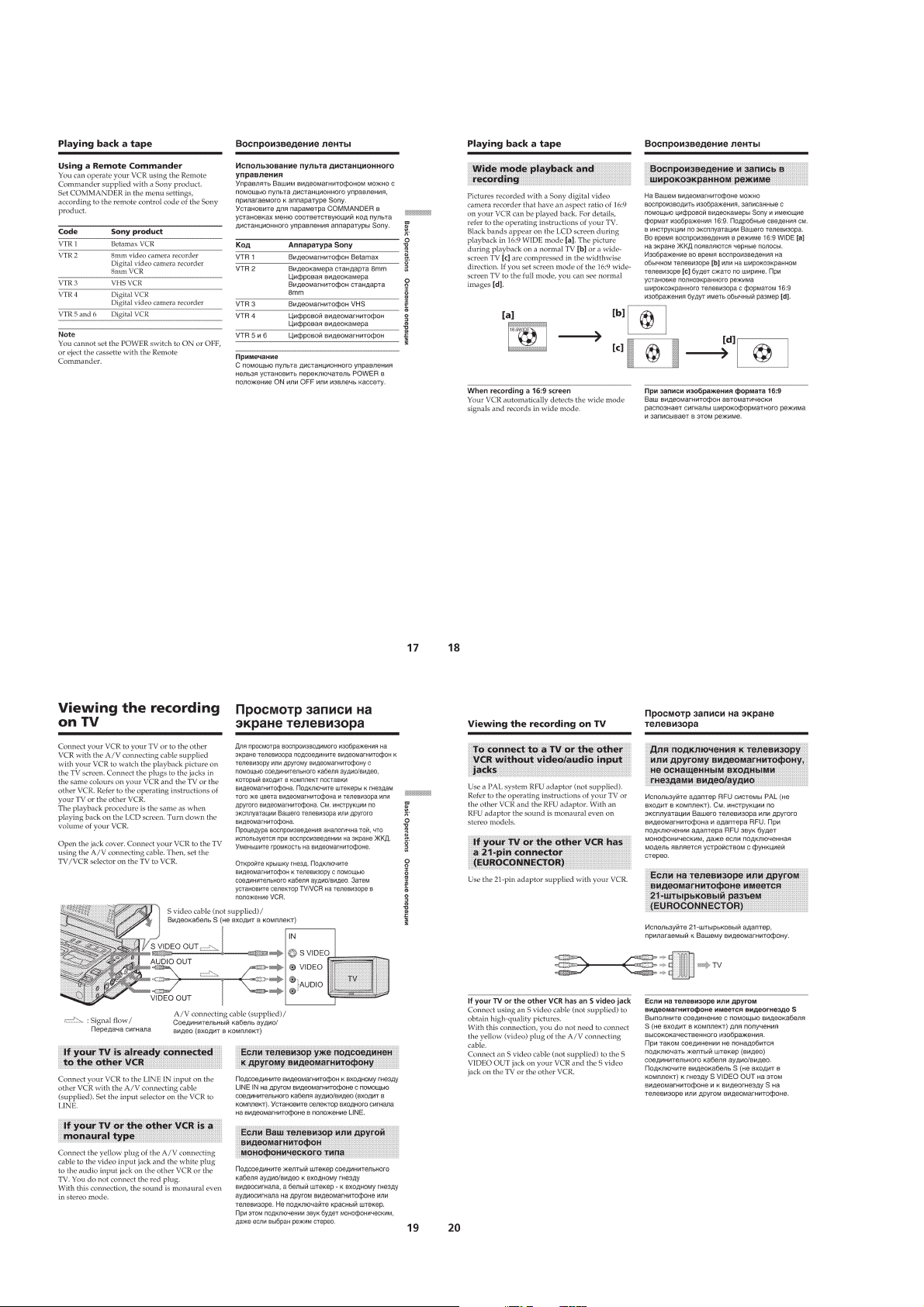
Playing back a tape ······························································· 1-3
Viewing the recording on TV ················································1-4
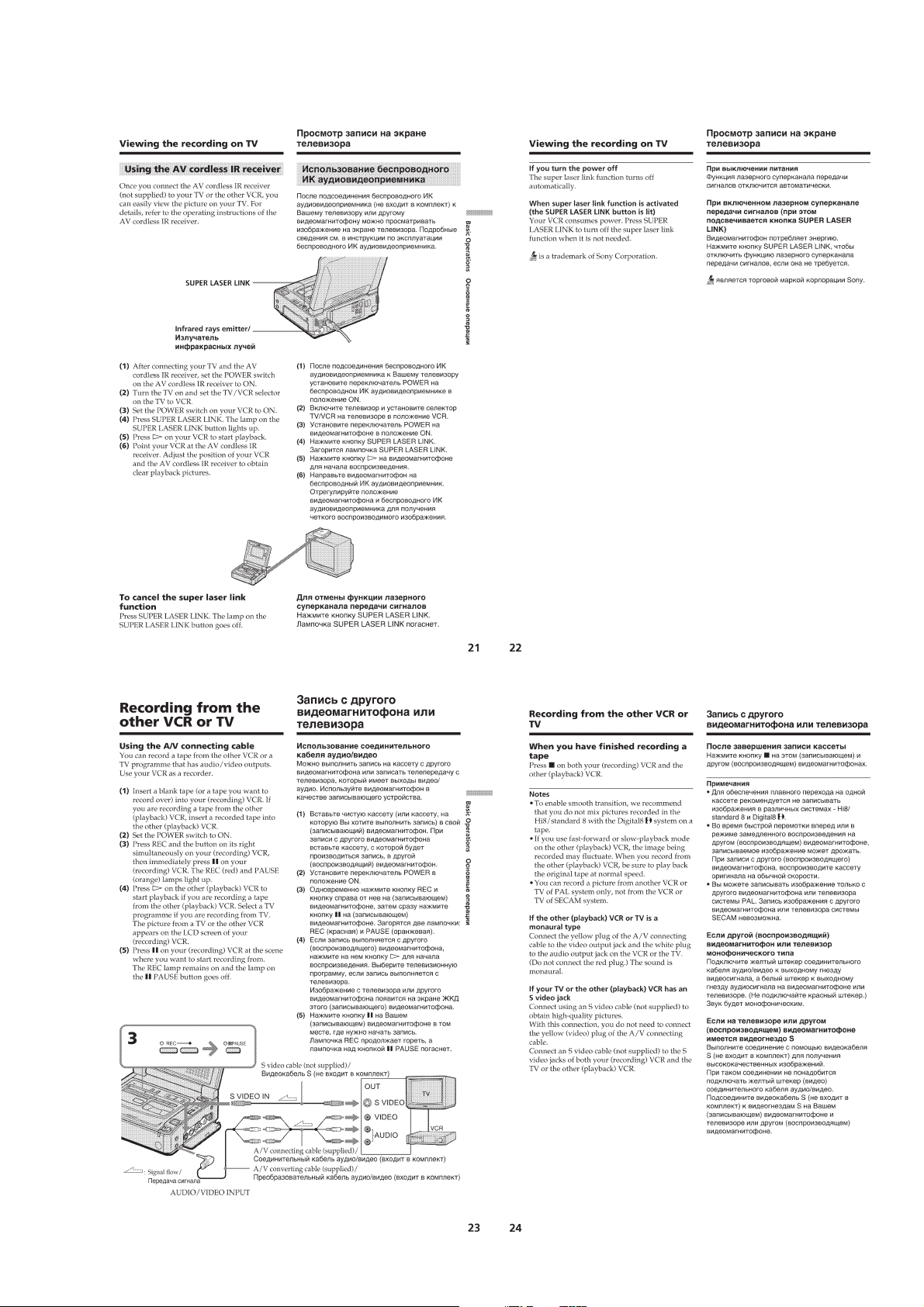
Recording from the other VCR or TV ···································1-5
Advanced operations
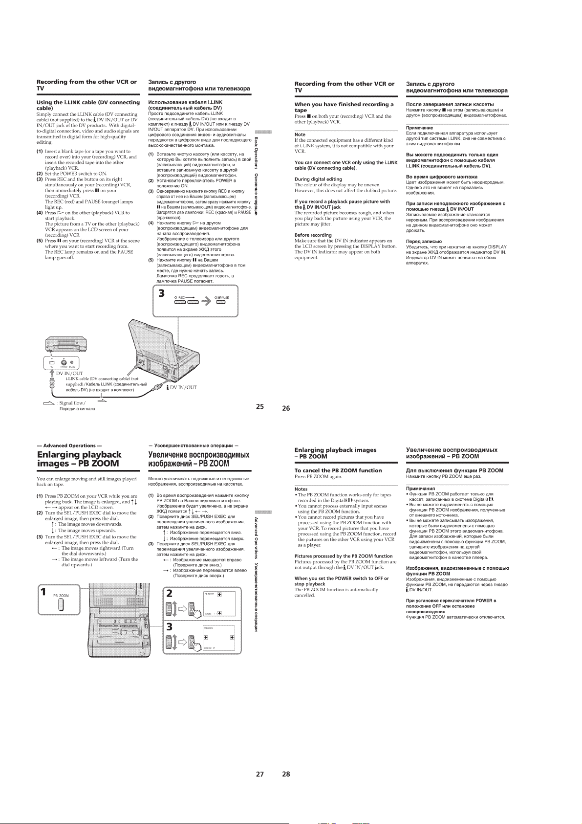
Enlarging playback images – PB ZOOM ······························1-6
Watching a tape with special effects – Picture effect·············1-7
Watching a tape with special performances – Digital effect··1-7
Quickly locating a scene – Zero set memory·························1-8
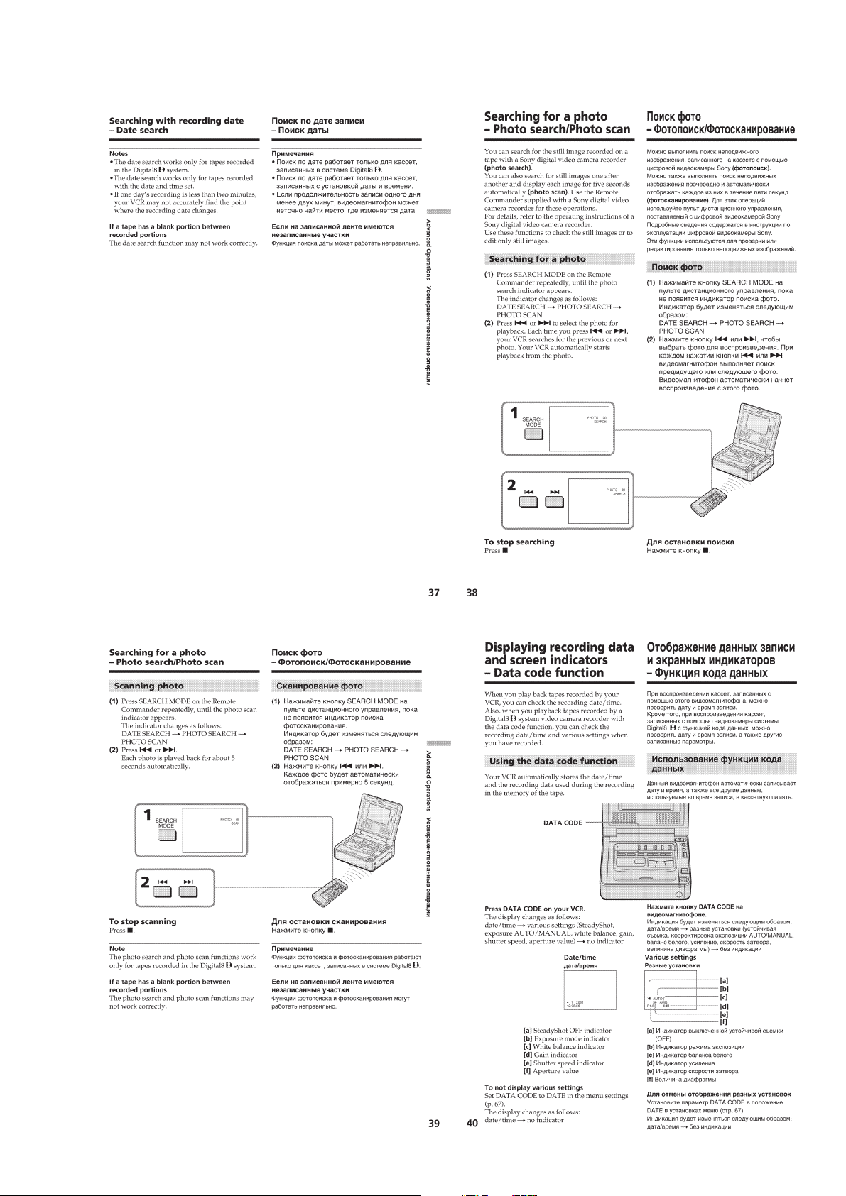
Searching with recording date – Date search ························1-8
Searching for a photo – Photo search/Photo scan··················1-9
Displaying recording data and screen indicators
– Data code function ······························································1-9
Superimposing a title ···························································1-10
Making your own titles ························································1-10
Editing
Dubbing a tape ·····································································1-11
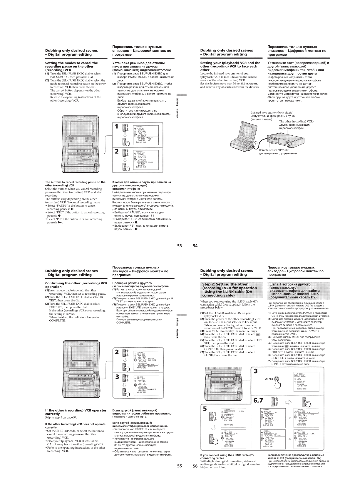
Dubbing only desired scenes – Digital program editing ·····1-12
Using with an analogue video unit and a personal computer
– Signal convert function·····················································1-15
Inserting a scene from the other (playback) VCR
– Insert Editing ····································································1-15
Customizing your VCR
Changing the menu settings·················································1-16
Resetting the date and time··················································1-17
Additional information
Digital8
About i.LINK·······································································1-19
Troubleshooting ···································································1-19
Self-diagnosis display ··························································1-20
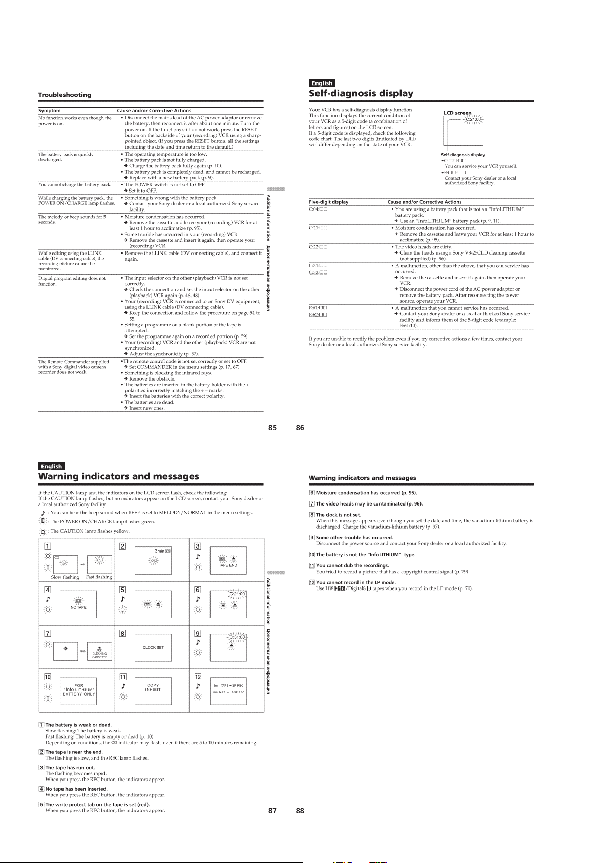
Warning indicators and messages ········································1-20
Using your VCR abroad ······················································ 1-21
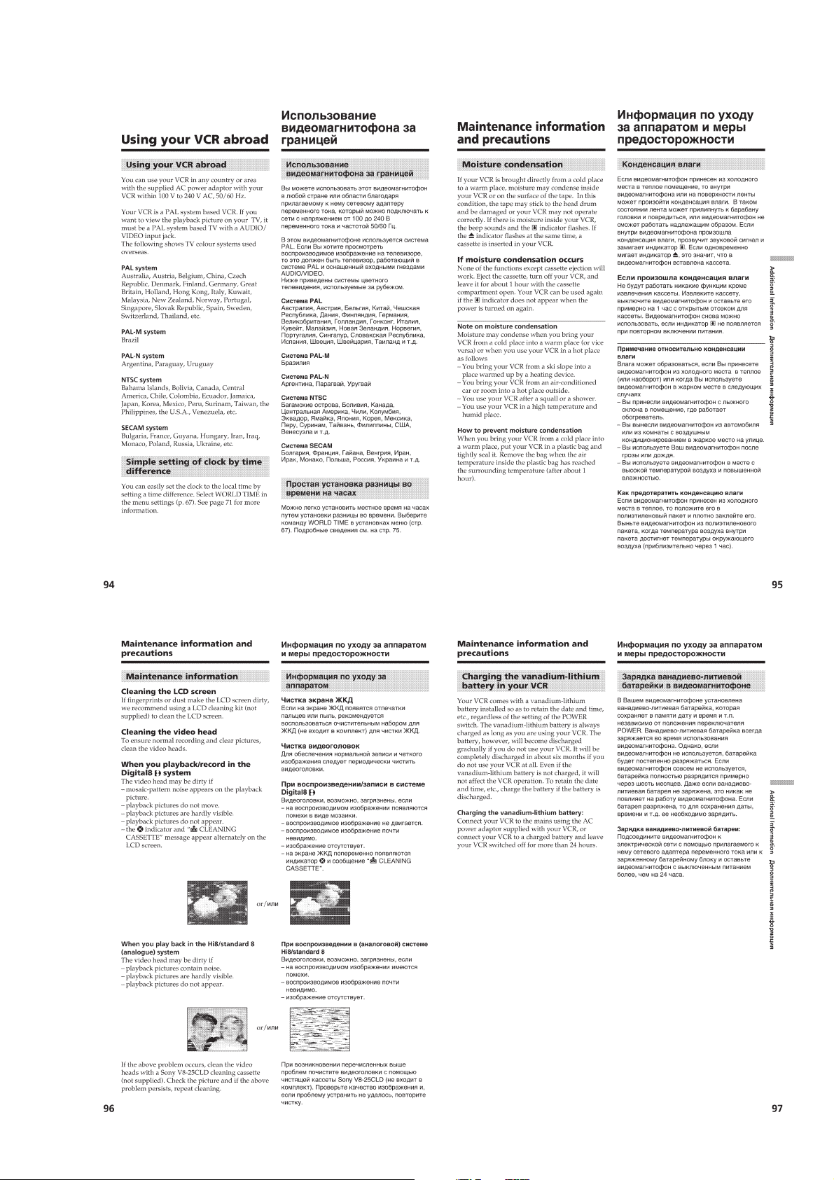
Maintenance information and precautions···························1-21
Quick reference
Identifying the parts and controls ········································ 1-22
system, recording, and playback·······················1-18
2. DISASSEMBLY
2-1. CASSETTE LID ASSEMBLY ········································2-2
2-2. BOTTOM CABINET ASSEMBLY, FP-571 FLEXIBLE
BOARD (LITHIUM BATTERY) ····································2-2
2-3.
LCD CABINET ASSEMBLY (D800, D800E MODEL)··
2-3
3. BLOCK DIAGRAMS
3-1. OVERALL BLOCK DIAGRAM (1/4) ···························3-1
3-2. OVERALL BLOCK DIAGRAM (2/4) ···························3-3
3-3. OVERALL BLOCK DIAGRAM (3/4) ···························3-5
3-4. OVERALL BLOCK DIAGRAM (4/4) ···························3-7
3-5. POWER BLOCK DIAGRAM (1/2)································3-9
3-6. POWER BLOCK DIAGRAM (2/2)······························3-11
4. PRINTED WIRING BOARDS AND
SCHEMATIC DIAGRAMS
4-1. FRAME SCHEMATIC DIAGRAM (1/2)·······················4-1
FRAME SCHEMATIC DIAGRAM (2/2)·······················4-3
4-2. PRINTED WIRING BOARDS AND
SCHEMATIC DIAGRAMS ············································4-5
• VC-250 (REC/PB AMP, DAC, DV INTERFACE,
AD CONVERTER, Y/C PROCESSOR, LINE A/D,
LINE I/O, IR, AUDIO I/O, DRUM/CAPSTAN
MOTOR DRIVE, MECHA CONTROL, HI CONTROL,
DC/DC CONVERTER, CONNECTION)
PRINTED WIRING BOARD ·························4-7
• VC-250 (REC/PB AMP)(1/16)
SCHEMATIC DIAGRAM····························4-11
• VC-250 (PB AMP, DAC)(2/16)
SCHEMATIC DIAGRAM····························4-13
• VC-250 (DV INTERFACE)(3/16)
SCHEMATIC DIAGRAM····························4-15
• VC-250 (DV INTERFACE)(4/16)
SCHEMATIC DIAGRAM····························4-17
• VC-250 (AD CONVERTER)(5/16)
SCHEMATIC DIAGRAM····························4-19
• VC-250 (Y/C PROCESSOR)(6/16)
SCHEMATIC DIAGRAM····························4-21
• VC-250 (LINE A/D)(7/16)
SCHEMATIC DIAGRAM····························4-23
• VC-250 (LINE IN/OUT)(8/16)
SCHEMATIC DIAGRAM····························4-25
• VC-250 (IR)(9/16)
SCHEMATIC DIAGRAM····························4-27
• VC-250 (MECHANISM CONTROL)(10/16)
SCHEMATIC DIAGRAM····························4-29
• VC-250 (AUDIO I/O)(11/16)
SCHEMATIC DIAGRAM····························4-31
• VC-250 (DRUM/CAPSTAN MOTOR DRIVE)(12/16)
SCHEMATIC DIAGRAM····························4-33
• VC-250 (MECHA CONTROL)(13/16)
SCHEMATIC DIAGRAM····························4-35
• VC-250 (HI CONTROL)(14/16)
SCHEMATIC DIAGRAM····························4-37
— 3 —

• VC-250 (DC/DC CONVERTER)(15/16)
SCHEMATIC DIAGRAM····························4-39
• VC-250 (CONNECTION)(16/16)
SCHEMATIC DIAGRAM····························4-41
• FP-575 (LANC), IO-68 (AV IN/OUT)
PRINTED WIRING BOARDS ·····················4-43
• IO-68 (AV IN/OUT)
SCHEMATIC DIAGRAM····························4-45
• FU-145 (DC/DC CONVERTER)
PRINTED WIRING BOARD ·······················4-47
• FU-145 (DC/DC CONVERTER)
SCHEMATIC DIAGRAM····························4-49
• PD-130 (LCD DRIVER, BACK-LIGHT)
PRINTED WIRING BOARD ·······················4-51
• LS-56 (LCD SWITCH)
PRINTED WIRING BOARD ·······················4-54
• PD-130 (LCD DRIVER, BACK-LIGHT)(1/2)
SCHEMATIC DIAGRAM····························4-55
• PD-130 (BACK-LIGHT)(2/2)
SCHEMATIC DIAGRAM····························4-57
• IR-38 (IR TRANSMITTER),
CONTROL SWITCH BLOCK (FK-78)
PRINTED WIRING BOARDS ·····················4-59
• CONTROL SWITCH BLOCK (FK-78)
SCHEMATIC DIAGRAM····························4-61
• EX-36 (MULTI CONNECTOR)
PRINTED WIRING BOARD ·······················4-63
• EX-36 (MULTI CONNECTOR)
SCHEMATIC DIAGRAM····························4-65
• FP-571 (BATTERY), FP-249 (S/T REEL)
PRINTED WIRING BOARDS ·····················4-67
4-3. WAVEFORMS ······························································4-68
4-4. MOUNTED PARTS LOCATION ·································4-70
5. ADJUSTMENTS
1. Before starting adjustment···············································5-1
1-1. Adjusting items when replacing main parts and boards.·5-2
5-1. ADJUSTMENT PREPARATIONS·································5-3
1-1. PREPARATIONS BEFORE ADJUSTMENT·················5-3
1-1-1.List of Service Tools ························································5-3
5-2. MECHANISM SECTION ADJUSTMENT····················5-4
2-1. Hi8/STANDARD8 MODE··············································5-4
2-1-1.OPERA TING WITHOUT CASSETTE ··························5-4
2-1-2.TAPE PATH ADJUSTMENT··········································5-4
1. Preparations for Adjustment············································ 5-4
2-2. DIGITAL8 MODE ··························································5-5
2-2-1.HOW TO ENTER RECORD MODE WITHOUT
CASSETTE ····································································· 5-5
2-2-2.HOW TO ENTER PLAYBACK MODE WITHOUT
CASSETTE ····································································· 5-5
2-2-3.OVERALL TAPE PATH CHECK ···································5-5
1. Recording of the tape path check signal·························· 5-5
2. Tape path check ······························································· 5-5
5-3. ELECTRICAL ADJUSTMENT······································5-6
3-1. PREPARATIONS BEFORE ADJUSTMENTS ·············· 5-6
3-1-1.Equipment to Required····················································5-6
3-1-2.Precautions on Adjusting·················································5-7
3-1-3.Adjusting Connectors ······················································5-7
3-1-4.Connecting the Equipment ·············································· 5-8
3-1-5.Alignment Tape ·······························································5-9
3-1-6.Input/output Level and Impedance ································5-10
3-2. INITIALIZATION OF C, D, E, F, 7, 8 PAGE DATA ···5-11
3-2-1.INITIALIZATION OF C, D, 8 PAGE DATA ················5-11
1. Initializing the C, D, 8 Page Data··································5-11
2. Modification of C, D, 8 Page Data ································5-11
3. C Page Table ··································································5-11
4. D Page Table··································································5-12
5. 8 Page Table···································································5-13
3-2-2.INITIALIZATION OF E, F, 7 PAGE DATA ·················5-14
1. Initializing the E, F, 7 Page Data ···································5-14
2. Modification of E, F, 7 Page Data ·································5-14
3. F Page Table ··································································5-14
4. E Page Table ··································································5-15
5. 7 Page Table···································································5-16
3-3. SYSTEM CONTROL SYSTEM ADJUSTMENT········5-17
1. Serial No. Input ·····························································5-17
1-1. Company ID Input·························································5-17
1-2. Serial No. Input ·····························································5-17
2. Battery End Adjustment ················································5-19
3-4. SERVO AND RF SYSTEM ADJUSTMENT ···············5-20
1. REEL FG Adjustment (VC-250 Board) ························5-20
2. PLL fo & LPF fo Pre-Adjustment (VC-250 Board)······5-20
3. Switching Position Adjustment (VC-250 Board)··········5-21
4. AGC Center Level and APC & AEQ Adjustment ·········5-21
4-1. Preparations before adjustments····································5-21
4-2. AGC Center Level Adjustment (VC-250 Board) ··········5-21
4-3. APC & AEQ Adjustment (VC-250 Board) ···················5-22
4-4. Processing after Completing Adjustments ···················· 5-22
5. PLL fo & LPF fo Final Adjustment (VC-250 Board) ···5-23
6. Hi8/Standard8 Switching Position Adjustment
(VC-250 Board)·····························································5-23
7. CAP FG Offset Adjustment (VC-250 board) ················5-24
3-5. VIDEO SYSTEM ADJUSTMENTS·····························5-25
1.
27MHz Origin Oscillation Adjustment (VC-250 board) ··
2. Chroma BPF fo Adjustment (VC-250 Board)···············5-25
3. S VIDEO OUT Y Level Adjustment (VC-250 Board) ··5-26
4. S VIDEO OUT Chroma Level Adjustment
(VC-250 Board)·····························································5-26
5.
VIDEO OUT Y, Chroma Level Check (VC-250 Board) ··
Hi8/Standard8 Y/C Output Level Setting (VC-250 Board)·
6.
7.
Hi8/standard 8mm AFC fo Adjustment (VC-250 board) ··
3-6. IR TRANSMITTER ADJUSTMENTS·························5-29
1.
IR Video Carrier Frequency Adjustment (VC-250 board)··
2. IR Video Deviation Adjustment (VC-250 board) ··········5-29
3. IR Audio Deviation Adjustment (VC-250 board) ·········5-30
3-7. AUDIO SYSTEM ADJUSTMENTS ····························5-31
1.
Hi8/Standard8 AFM BPF fo Adjustment (VC-250 board)··
2. Hi8/Standard8 AFM 1.5 MHz Deviation Adjustment
(VC-250 board) ·····························································5-32
3. Hi8/Standard8 AFM 1.7 MHz Deviation Adjustment
(VC-250 board) ·····························································5-32
4. Digital8 Playback Level Check ·····································5-32
5. Overall Level Characteristics Check ·····························5-32
6. Overall Distortion Check···············································5-32
7. Overall Noise Level Check············································5-33
8. Overall Separation Check·············································· 5-33
3-8. LCD SYSTEM ADJUSTMENT (GV-D800/D800E) ···5-34
1. LCD Initial Data Input (1)·············································5-34
2. LCD Initial Data Input (2)·············································5-35
3. VCO Adjustment (PD-130 board)·································5-35
4. RGB AMP Adjustment (PD-130 board)························5-36
5. Contrast Adjustment (PD-130 board)····························5-36
6. COM AMP Adjustment (PD-130 board)·······················5-37
7. V-COM Adjustment (PD-130 board) ····························5-37
8. White Balance Adjustment (PD-130 board)··················5-38
5-4. SERVICE MODE··························································5-39
4-1. ADJUSTMENT REMOTE COMMANDER ················5-39
1. Using the Adjustment Remote Commander··················5-39
2. Precautions Upon Using the Adjustment Remote
Commander ··································································· 5-39
4-2. DATA PROCESS···························································5-40
4-3. SERVICE MODE··························································5-41
1. Setting the Test Mode ····················································5-41
2. Emergence Memory Address ········································5-41
5-25
5-27
5-27
5-28
5-29
5-31
— 4 —

2-1. C Page Emergence Memory Address ····························5-41
2-2. F Page Emergence Memory Address ····························5-42
2-3. EMG Code (Emergency Code) ·····································5-42
2-4. MSW Code ····································································5-43
3. Bit V alue Discrimination ···············································5-44
4. Switch check (1) ····························································5-44
5. Switch check (2) ····························································5-44
6. Switch check (3) ····························································5-44
7. Switch check (4) ····························································5-45
8. Record of Use check······················································5-45
9. Record of Self-diagnosis check ·····································5-46
6. REPAIR PARTS LIST
6-1. EXPLODED VIEWS ······················································6-1
6-1-1.OVERALL SECTION-1 ················································· 6-1
6-1-2.OVERALL SECTION-2 ················································· 6-2
6-1-3.LCD SECTION (D800/D800E MODEL) ·······················6-3
6-1-4.MECHANISM SECTION···············································6-4
6-1-5.CASSETTE COMPARTMENT ASSEMBLY ················6-5
6-1-6.LS CHASSIS ASSEMBLY ·············································6-6
6-1-7.MECHANISM CHASSIS ASSEMBLY ························· 6-7
6-2. ELECTRICAL PARTS LIST ··········································6-8
— 5 —

SERVICE NOTE
1. POWER SUPPLY DURING REPAIRS
In this unit, about 10 seconds after power is supplied (8.4V) to the battery terminal using the service power code (J-6082-223-A), the power
is shut off so that the unit cannot operate.
These following two methods are available to prevent this. Take note of which to use during repairs.
Method 1:
Connect the adjustment remote commander RM-95 (J-6082-053-B) to the LANC jack, and set the HOLD switch to the “ADJ” side.
Method 2:
Use the DC IN terminal. (Use the AC power adaptor. (AC-L10, AC-VQ800 etc.))
2. TO TAKE OUT A CASSETTE WHEN NOT EJECT (FORCE EJECT) (1)
1 Remove the power supply (Battery or AC power adaptor).
2 Push the EJECT switch and open the cassette lid.
3 Refer to 2-2. to remove the cabinet (lid) assembly.
4 Refer to 2-2. to remove the cabinet (bottom) assembly.
5 Add 5V from the regulated power supply between Pin 5, 6 of CN4401 (ULD5V +) and Pin 7, 8 of CN4401 (ULD5V –), and unload
the cassette.
VC-250 board
CN4401
8
ULD
5V
1
Regulated
power supply (+5V)
— 6 —
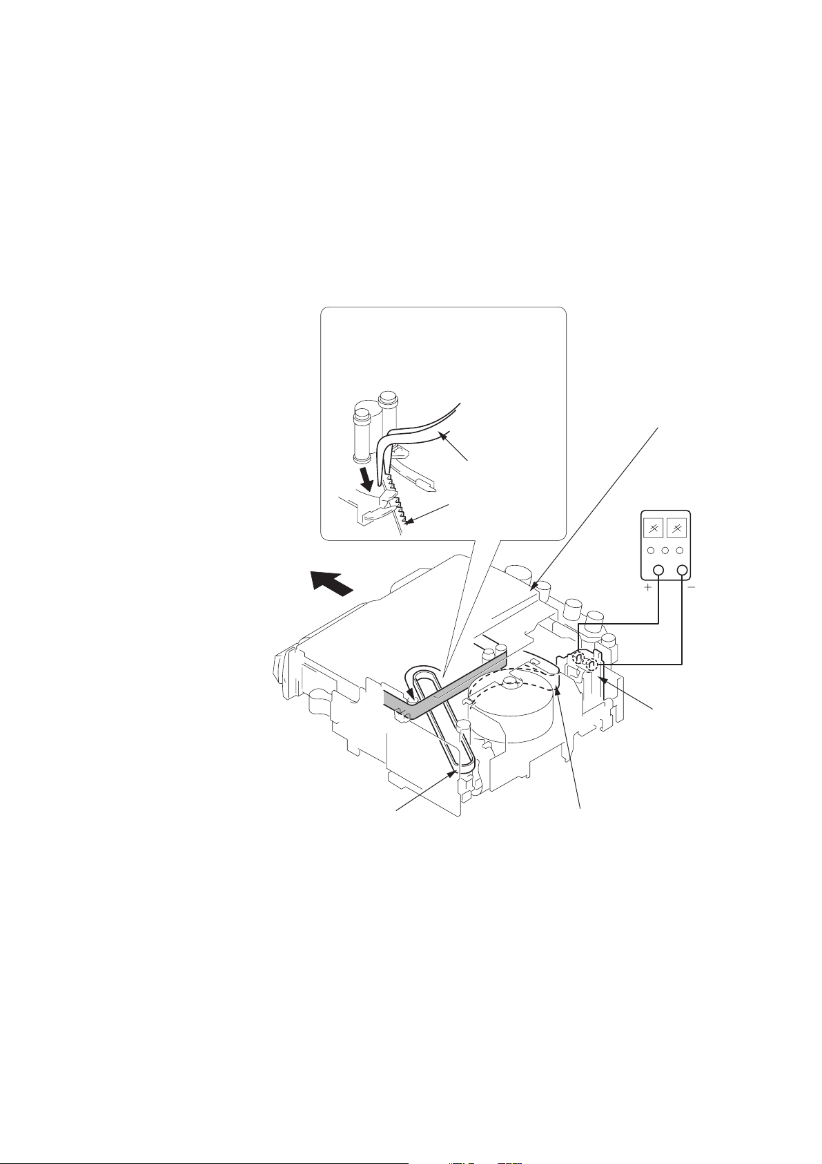
3. TO TAKE OUT A CASSETTE WHEN NOT EJECT (FORCE EJECT) (2)
(TO TAKE OUT A CASSETTE WITHOUT HURTING THE TAPE)
1 Disconnect the power supply (Battery or AC adaptor)
2 Refer to 2-2. to remove the cabinet (lid) assembly.
3 Refer to 2-2. to remove the cabinet (bottom) assembly.
4 Refer to 2-1. to remove the Cassette (lid) assembly.
5 Refer to 2-6 to 2-8. to remove the LCD block (GV-D800/D800E only) and the cabinet (upper) assembly.
6 Remove the FU-145 board.
7 Refer to 2-9. to remove the lid frame assembly.
8 Add +5V from the regulated power supply and unload with a pressing the cassette lid.
9
Pull the timing belt in the direction of
A
arrow
the cassette lid (take care not to damage)
to adjust the bending of a tape.
with a pincette while pressing
Press the cassette lid not to rise
the cassette compartment
0
Let go your hold the cassette
lid and rise the cassette
compartment to take out a cassette.
Timing belt
Pincette
Timing belt
Regulated
power supply
(+5V)
Loading motor
Adjust the bending of a tape
— 7 —
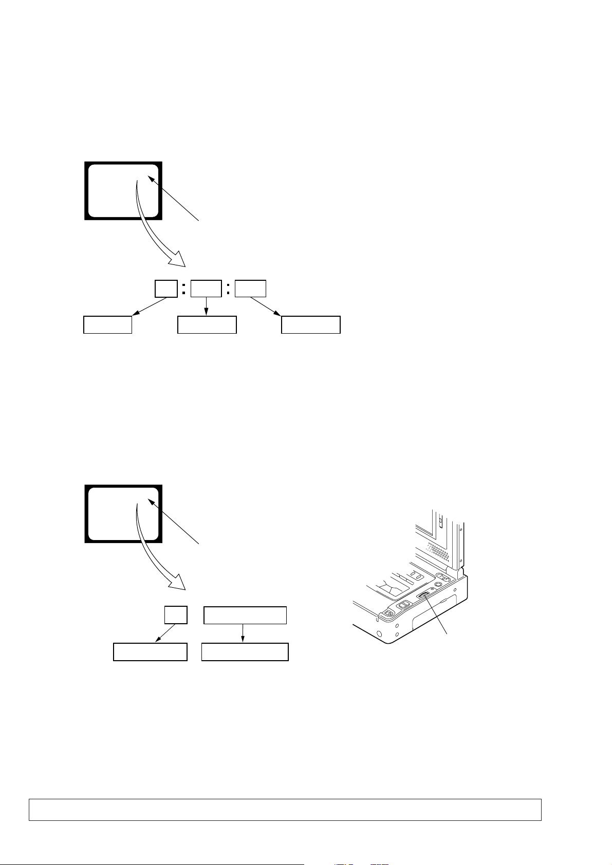
SELF-DIAGNOSIS FUNCTION
1. SELF-DIAGNOSIS FUNCTION
When problems occur while the unit is operating, the self-diagnosis
function starts working, and displays on the LCD screen or monitor
TV (Note) what to do. This function consists of two display; selfdiagnosis display and service mode display.
Details of the self-diagnosis functions are provided in the Instruction
manual.
LCD screen or monitor TV
C : 3 1 : 1 1
Repaired by:
C : Corrected by customer
H : Corrected by dealer
E : Corrected by service
engineer
Blinks at 3.2Hz
3 1C
Block
Indicates the appropriate
step to be taken.
E.g.
31 ....Reload the tape.
32 ....Turn o n power again.
1 1
2. SELF-DIAGNOSIS DISPLAY
When problems occur while the unit is operating, the counter of the
viewfinder shows a 4-digit display consisting of an alphabet and
numbers, which blinks at 3.2 Hz. This 5-character display indicates
the “repaired by:”, “block” in which the problem occurred, and
“detailed code” of the problem.
Note: Set the DISPLAY in the menu system to V-OUT/LCD only for the
model with LCD screen, and press the DISPLAY button.
Detailed Code
Refer to page 9.
Self-diagnosis Code Table.
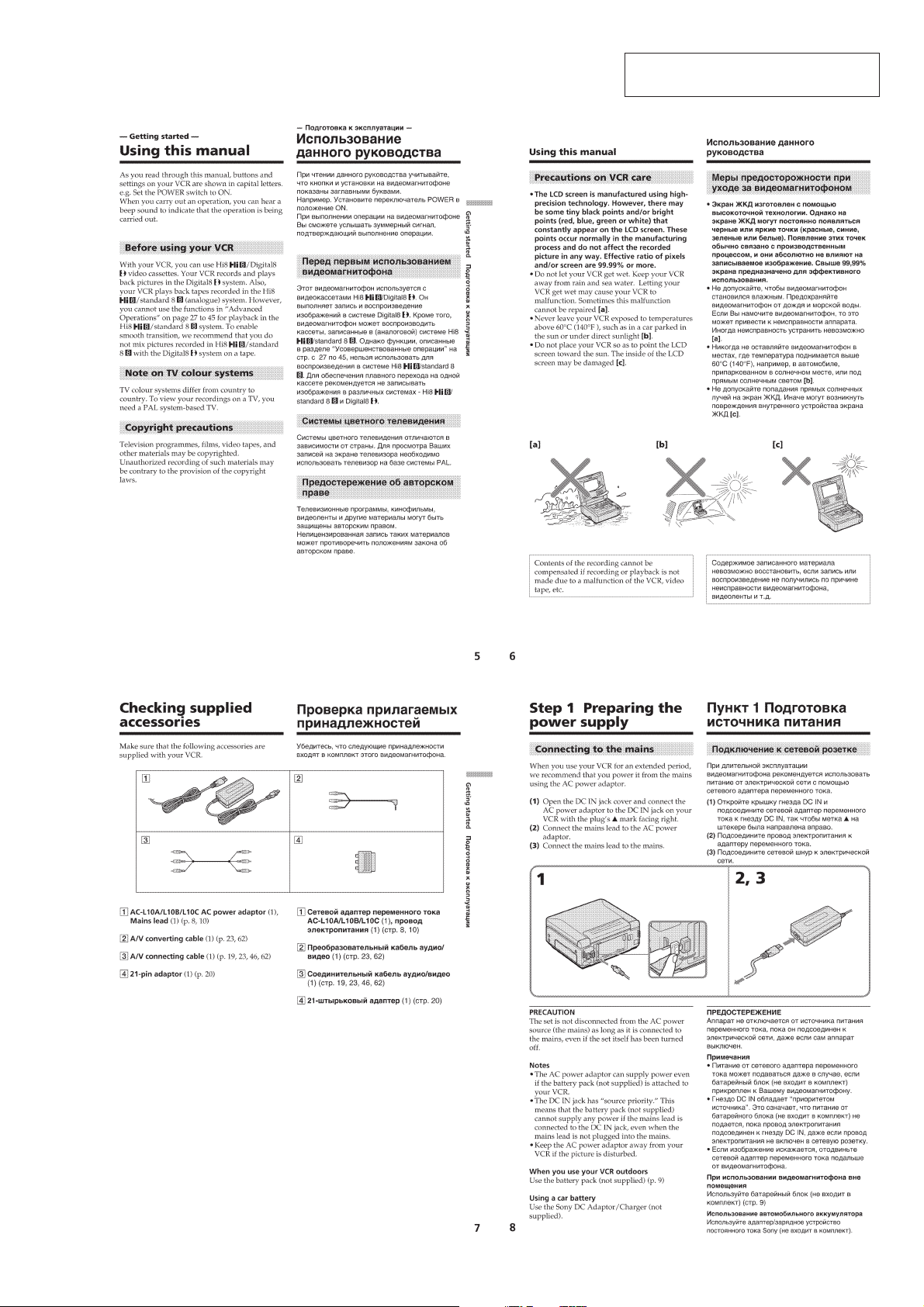
3. SER VICE MODE DISPLAY
The service mode display shows up to six self-diagnosis codes shown in the past.
3-1. Display Method
While pressing the “STOP” key , set the PO WER switch from OFF to ON, and continue pressing the “STOP” ke y for 10 seconds continuously .
The service mode will be displayed, and the counter will show the backup No. and the 5-character self-diagnosis codes.
LCD screen or monitor TV
[3] C : 3 1 : 1 1
Lights up
[3]
Backup No.
Order of previous errors
3-2. Switching of Backup No.
By rotating the control dial, past self-diagnosis codes will be shown in order. The backup No. in the [] indicates the order in which the
problem occurred. (If the number of problems which occurred is less than 6, only the number of problems which occurred will be shown.)
[1] : Occurred first time [4] : Occurred fourth time
[2] : Occurred second time [5] : Occurred fifth time
[3] : Occurred third time [6] : Occurred the last time
C : 3 1 : 1 1
Control dial
self-diagnosis codes
3-3. End of Display
Turning OFF the power supply will end the service mode display.
Note: The “self-diagnosis displa y” data will be backed up by the coin-type lithium battery of FP-571 flexible board. When this coin-type lithium ba ttery
is removed, the “self-diagnosis display” data will be lost by initialization.
— 8 —

4. SELF-DIAGNOSIS CODE TABLE
Self-diagnosis Code
Function
Repaired by:
C
C
C
C
C
C
C
C
C
C
C
C
C
C
C
C
C
C
C
C
C
C
C
Block
04
21
22
31
31
31
31
31
31
31
31
31
31
31
31
32
32
32
32
32
32
32
32
Detailed
Code
00
00
00
10
11
20
21
22
23
24
30
40
42
10
11
20
21
22
23
24
30
40
42
Symptom/State
Non-standard battery is used.
Condensation.
Video head is dirty.
LOAD direction. Loading does not
complete within specified time
UNLOAD direction. Loading does not
complete within specified time
T reel side tape slacking when unloading
Winding S reel fault when counting the
rest of tape.
T reel fault.
S reel fault.
T reel fault.
FG fault when starting capstan.
FG fault when starting drum.
FG fault during normal drum operations.
LOAD direction loading motor time-
out.
UNLOAD direction loading motor
time-out.
T reel side tape slacking when
unloading.
Winding S reel fault when counting the
rest of tape.
T reel fault.
S reel fault.
T reel fault.
FG fault when starting capstan.
FG fault when starting drum
FG fault during normal drum
operations
Correction
Use the info LITHIUM battery.
Remove the cassette, and insert it again after one hour.
Clean with the optional cleaning cassette.
Load the tape again, and perform operations from the beginning.
Load the tape again, and perform operations from the beginning.
.
Load the tape again, and perform operations from the beginning.
Load the tape again, and perform operations from the beginning.
Load the tape again, and perform operations from the beginning.
Load the tape again, and perform operations from the beginning.
Load the tape again, and perform operations from the beginning.
Load the tape again, and perform operations from the beginning.
Load the tape again, and perform operations from the beginning.
Load the tape again, and perform operations from the beginning.
Remove the battery or power cable, connect, and perform
operations from the beginning.
Remove the battery or power cable, connect, and perform
operations from the beginning.
Remove the battery or power cable, connect, and perform
operations from the beginning.
Remove the battery or power cable, connect, and perform
operations from the beginning.
Remove the battery or power cable, connect, and perform
operations from the beginning.
Remove the battery or power cable, connect, and perform
operations from the beginning.
Remove the battery or power cable, connect, and perform
operations from the beginning.
Remove the battery or power cable, connect, and perform
operations from the beginning.
Remove the battery or power cable, connect, and perform
operations from the beginning.
Remove the battery or power cable, connect, and perform
operations from the beginning.
— 9 —
SECTION 1
GENERAL
GV-D200/D200E/D800/D800E
This section is extracted from instruction
manual. (GV-D800E model)
1-1

1-2

1-3
1-4
1-5
1-6

1-7

1-8
1-9

1-10

1-11

1-12
1-13

1-14

1-15

1-16

1-17

1-18
1-19
1-20
1-21
 Loading...