

Sony Cyber-shot DSC-P71, Cyber-shot DSC-P71M Service Manual
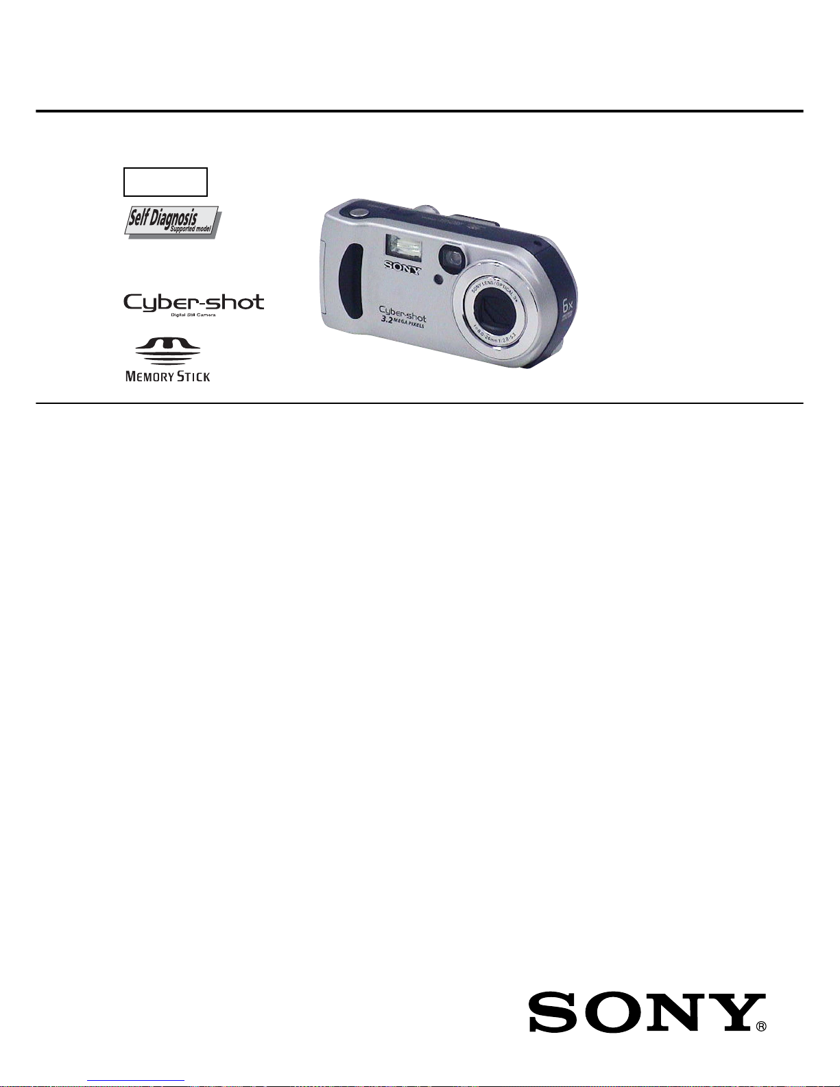
SERVICE MANUAL
DIGITAL STILL CAMERA
US Model
DSC-P71/P71M
Canadian Model
AEP Model
UK Model
E Model
Hong Kong Model
Australian Model
Chinese Model
Korea Model
Tourist Model
Japanese Model
DSC-P71
Level 3
SPECIFICATIONS
This service manual contains information for Japanese model as well.
Ver 1.2 2002. 11
DSC-P71/P71M
System
Image device
8.93mm (1/1.8 type) color
CCD
Primary color filter
Effective pixels number of camera
Approx. 3 210 000 pixels
Lens
3×zoom lens
f=8~24.0 mm (35 mm camera
conversion: 39 to 117mm)
F2.8~5.3
Exposure control
Automatic,
Scene Selection (3 mode)
White balanceAutomatic, Daylight, Cloudy,
Fluorescent, Incandescent
Data formats Moving images: MPEG1
Still images: JPEG, GIF F(for Clip
Motion)
Recording media
“Memory Stick”
Flash Recommended distance
0.5 to 3.8 m (1.6 to 12.5
ft) (W)
0.5 to 2.5 m (1.6 to 8.2 ft) (T)
(when ISO sensitivity is set to Auto)
Output connectors
VIDEO OUT jack
Minijack
1 Vp-p, 75 ohm, unbalanced, sync
negative
USB jack mini-B
LCD screen
LCD panel used
3.8 cm (1.5 type) TFT drive
Total number of dots
123 200 (560x220) dots
Power, etc.
Power AA nickel hydride batteries (2)
2.4 V
AC- LS1 AC powe r ad apt or
(not supplied), 4.2 V
Power consumption (when recording)
2.1W
Operating temperature range
0° to
+
40°C (32° to+104°F)
Storage temperature range
−
20° to +60°C (−4° to+140°F)
Dimensions
124.9 ×58 ×43.6 mm (5 ×2
3
/
8
1 3/4inches)
(W/H/D, protruding portions not
included)
Mass
284 g (10 oz) (camera, two batteries,
“Memory Stick” and wrist strap
included)
BC-CS1 Ni-MH battery charger
Power requirements
AC 100 to 240V 50/60Hz
2.2 W
Output voltage
DC 1.8V 180/110 mA 2
Dimensions 70 ×29 ×74 mm (2
7
/8×1 3/16×3
inches) (W/H/D)
Mass Approx. 70g (2 oz)
Operating temperature range
0° to +40°C (32° to +104°F)
AC-LS1 AC power adaptor (not
supplied)
Power requirements
AC 100 – 240 V, 50/60 Hz
Rated output voltage
DC 4.2 V, 1.5 A
External dimensions
105 ×36 ×56 mm (4
1
/4× ×
1 7/
16
2 1/4)(W/H/D, protruding parts not
included)
Mass Approx. 180 g (6 oz)
(adaptor only)
Operating temperature range
0° to
+
40°C (32° to+104°F)
Storage temperature range
−
20° to+60°C (−4° to +140°F)
Accessories
•Video connector cable (1)
•R6 (size AA) Ni-MH batteries (2)
•Ni-MH Battery charger (1)
•Power cord (mains lead) (1)
•USB cable (1)
•Wrist strap
•“Memory Stick” (16MB) (1)
•CD-ROM (USB driver: SPVD-008) (1)
•CD-ROM (for Customer registration) (1)
•Operation Instructions (1)
Design and specifications are subject to change
without notice.
×

– 2 –
DSC-P71/P71M
1. Check the area of your repair for unsoldered or poorly-soldered connections. Check the entire board surface for solder
splashes and bridges.
2. Check the interboard wiring to ensure that no wires are
“pinched” or contact high-wattage resistors.
3. Look for unauthorized replacement parts, particularly transistors, that were installed during a previous repair. Point them
out to the customer and recommend their replacement.
4. Look for parts which, though functioning, show obvious signs
of deterioration. Point them out to the customer and recommend their replacement.
5. Check the B+ voltage to see it is at the values specified.
6. Flexible Circuit Board Repairing
•Keep the temperature of the soldering iron around 270 ˚C
during repairing.
• Do not touch the soldering iron on the same conductor of
the circuit board (within 3 times).
• Be careful not to apply force on the conductor when sol-
dering or unsoldering.
SAFETY CHECK-OUT
After correcting the original service problem, perform the following
safety checks before releasing the set to the customer.
ATTENTION AU COMPOSANT AYANT RAPPORT
À LA SÉCURITÉ!
LES COMPOSANTS IDENTIFIÉS P AR UNE MARQUE 0
SUR LES DIAGRAMMES SCHÉMA TIQUES ET LA LISTE
DES PIÈCES SONT CRITIQUES POUR LA SÉCURITÉ
DE FONCTIONNEMENT. NE REMPLACER CES COMPOSANTS QUE PAR DES PIÈCES SONY DONT LES
NUMÉROS SONT DONNÉS DANS CE MANUEL OU
DANS LES SUPPLÉMENTS PUBLIÉS PAR SONY.
SAFETY-RELATED COMPONENT WARNING!!
COMPONENTS IDENTIFIED BY MARK 0 OR DOTTED
LINE WITH MARK 0 ON THE SCHEMATIC DIAGRAMS
AND IN THE PARTS LIST ARE CRITICAL TO SAFE
OPERATION. REPLACE THESE COMPONENTS WITH
SONY PARTS WHOSE PART NUMBERS APPEAR AS
SHOWN IN THIS MANUAL OR IN SUPPLEMENTS PUBLISHED BY SONY.
UNLEADED SOLDER
Boards requiring use of unleaded solder are printed with the leadfree mark (LF) indicating the solder contains no lead.
(Caution: Some printed circuit boards may not come printed with
the lead free mark due to their particular size)
: LEAD FREE MARK
Unleaded solder has the following characteristics.
• Unleaded solder melts at a temperature about 40 ˚C higher than
ordinary solder.
Ordinary soldering irons can be used but the iron tip has to be
applied to the solder joint for a slightly longer time.
Soldering irons using a temperature regulator should be set to
about 350 ˚C .
Caution: The printed pattern (copper foil) may peel away if the
heated tip is applied for too long, so be careful!
• Strong viscosity
Unleaded solder is more viscous (sticky, less prone to flo w) than
ordinary solder so use caution not to let solder bridges occur
such as on IC pins, etc.
• Usable with ordinary solder
It is best to use only unleaded solder but unleaded solder may
also be added to ordinary solder.
CAUTION
Use of controls or adjustments or performance
procedures other than those specified herein may
result in hazardous radiation exposure.
Table for differences of function
Model DSC-P71
DSC-P71M
(Note)
Destination
US, Canadian, AEP, UK
US
E, J, Hong Kong,
Australian, Chinese,
Korea, Tourist
Note: DSC-P71M is the same as DSC-P71 (US model) except packing materials.
Therefore, information about DSC-P71 (US model) in the text is applied.

– 3 –
DSC-P71/P71M
SERVICE NOTE ................................................................... 5
Self-diagnosis Display .......................................................... 6
1. GENERAL
Before using your camera ....................................................... 1-2
Identifying the Parts................................................................. 1-4
Preparing batteries .................................................................. 1-5
Charging the batteries ............................................................. 1-5
Inserting the batteries ............................................................. 1-6
Using an external power source ............................................. 1-7
Using your camera abroad...................................................... 1-7
Turning on/off your camera ..................................................... 1-8
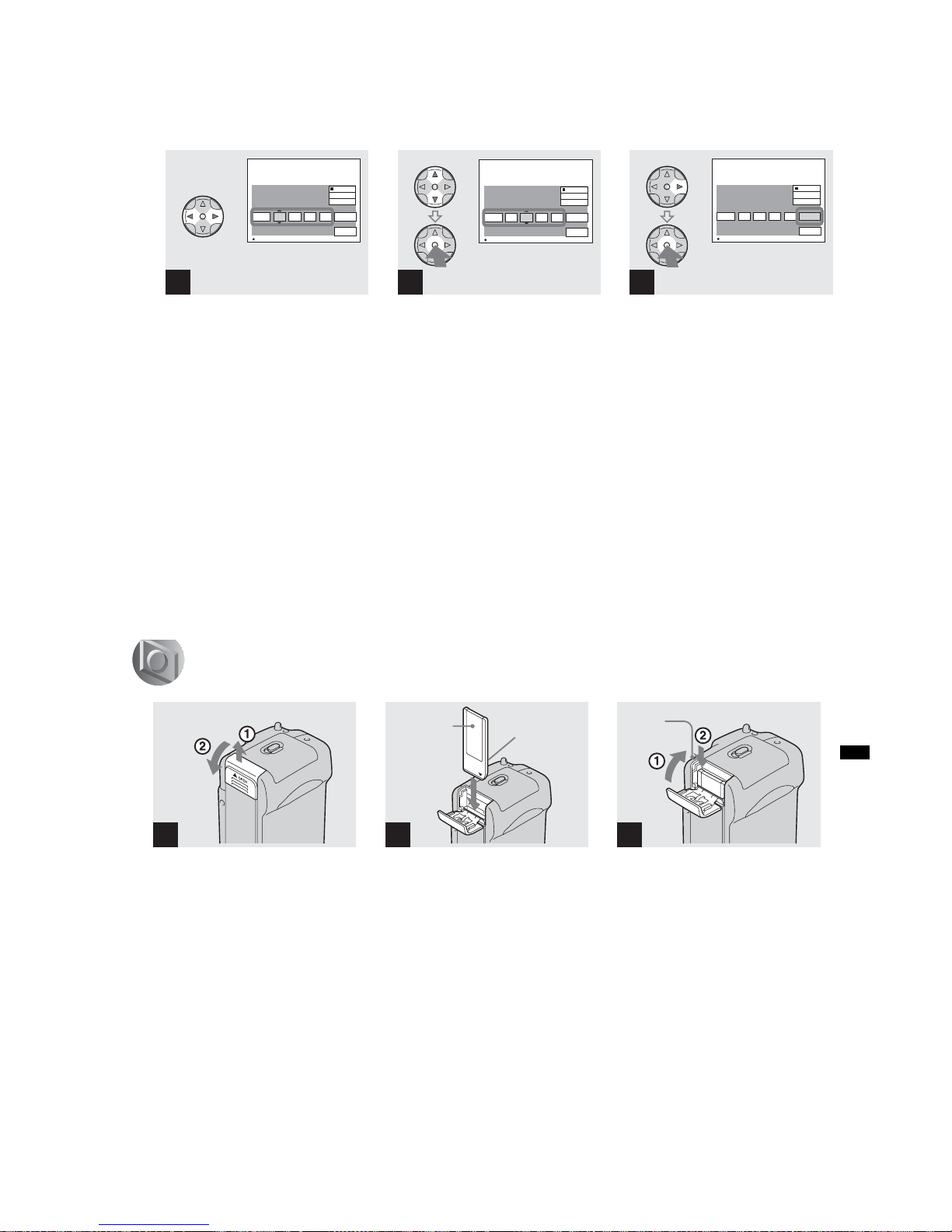
How to use the control button ................................................. 1-8
Setting the data and time ........................................................ 1-8
Inserting and removing a “Memory Stick” ............................... 1-9
Deciding the still image size and image quality...................... 1-10
Basic still image shooting (using auto adjustment mode) ...... 1-11
Viewing images on the LCD screen of your camera .............. 1-16
Viewing images on a TV screen .............................................. 1-17
Deleting still images ................................................................ 1-17
Formatting a “Memory Stick” ................................................... 1-19
Copying still images to your Computer ................................... 1-20
Installing the USB driver.......................................................... 1-20
Preparing your camera............................................................ 1-21
Connecting your camera to your computer............................. 1-21
Copying images....................................................................... 1-22
Viewing the images on your computer.................................... 1-24
For Macintosh users ................................................................ 1-25
How to setup and operate your camera.................................. 1-25
Troubleshooting ....................................................................... 1-39
Warning and Messages........................................................... 1-42
Self-Diagnostics Display.......................................................... 1-43
Menu items .............................................................................. 1-44
SET UP items .......................................................................... 1-46
The LCD screen ...................................................................... 1-48
2. DISASSEMBLY
2-1. Cabinet (Rear) Block Assembly .................................... 2-2
2-2. PK-064 Board ................................................................ 2-2
2-3. LCD Module................................................................... 2-3
2-4. Cabinet (Front) Block Assembly.................................... 2-3
2-5. Cabinet (Upper) Block Assembly .................................. 2-4
2-6. ST-075 Board................................................................. 2-4
2-7. Lens Block Assembly .................................................... 2-5
2-8. Memory Stick Connector............................................... 2-5
2-9. CD-392 Board ............................................................... 2-6
2-10. JK-231 Board ................................................................ 2-6
2-11. SY-075 Board ................................................................ 2-7
Service Position (SY-075 Board: Side B)...................... 2-7
Service Position (SY-075 Board: Side A)...................... 2-8
2-12. Circuit Boards Location ................................................. 2-9
2-13. Flexible Board Location................................................. 2-10
3. BLOCK DIAGRAMS
3-1. Overall Block Diagram .................................................. 3-1
3-2. Camera Block Diagram 1 .............................................. 3-3
3-3. Camera Block Diagram 2 .............................................. 3-5
3-4. Lens Motor Drive Block Diagram .................................. 3-7
3-5. Video Flash Mode Control Block Diagram.................... 3-9
3-6. LCD Block Diagram....................................................... 3-11
3-7. Power Block Diagram 1................................................. 3-13
3-8. Power Block Diagram 2................................................. 3-15
TABLE OF CONTENTS
Section Title Page Section Title Page
4. PRINTED WIRING BOARDS AND
SCHEMATIC DIAGRAMS
4-1. Frame Schematic Diagrams.......................................... 4-1
Frame Schematic Diagram (1/2) ................................... 4-1
Frame Schematic Diagram (2/2) ................................... 4-3
4-2. Schematic Diagrams ..................................................... 4-5
CD-392 (CCD IMAGER) ............................................... 4-7
CH-109 (CAMERA PROCESS) .................................... 4-9
SY-075 (1/8) (CAMERA DSP) ....................................... 4-11
SY-075 (2/8) (VIDEO, MEMORY) ................................. 4-13
SY-075 (3/8) (LENS DRIVE) ......................................... 4-15
SY-075 (4/8) (SH DSP) ................................................. 4-17
SY-075 (5/8)
(FLASH MEMORY CLOCK GENERATOR) .................. 4-19
SY-075 (6/8) (CONNECTOR)........................................ 4-21
SY-075 (7/8) (DC IN) ..................................................... 4-23
SY-075 (8/8) (DC/DC CONVERTER)............................ 4-25
PK-064 (1/3) (FRONT CONTROL) ............................... 4-27
PK-064 (2/3) (LCD DRIVE, TIMING GENERATOR)..... 4-29
PK-064 (3/3) (CONTROL SWITCH) ............................. 4-31
JK-231 (JACK) ............................................................... 4-32
ST-075 (FLASH DRIVE) ................................................ 4-33
4-3. Printed Wiring Boards ................................................... 4-37
CD-392 .......................................................................... 4-39
CH-109 .......................................................................... 4-41
SY-075 ........................................................................... 4-43
PK-064........................................................................... 4-47
JK-231 ........................................................................... 4-51
ST-075 ........................................................................... 4-53
4-4. Waveforms..................................................................... 4-57
4-5. Parts Location ............................................................... 4-61
5. ADJUSTMENTS
Before Starting Adjustment ..................................................... 5-1
1-1. Adjusting Items when Replacing
Main Parts and Boards.................................................. 5-2
5-1. Camera Section Adjustments........................................ 5-3
1-1. Preparations Before Adjustment ................................... 5-3
1-1-1. List of Service Tools ................................................. 5-3
1-1-2. Preparations............................................................. 5-4
1-1-3. Discharging of the Flashlight Power Supply............ 5-4
1-1-4. Precautions .............................................................. 5-6
1. Setting the Switch .................................................... 5-6
2. Order of Adjustments ............................................... 5-6
3. Subjects.................................................................... 5-6
4. Preparing the Flash Adjustment Box ....................... 5-7
1-2. Initialization of A, B, D, E, F, 7, 9 Page Data ................ 5-8
1-2-1. Initialization of A, D Page Data ................................ 5-8
1. Initializing A, D Page Data ....................................... 5-8
2. Modification of A, D Page Data ................................ 5-8
3. A Page Table ............................................................ 5-8
4. D Page Table ............................................................ 5-8
1-2-2. Initialization of B, E, F, 7, 9 Page Data .................... 5-9
1. Initializing B, E, F, 7, 9 Page Data ........................... 5-9
2. Modification of B, E, F, 7, 9 Page Data.................... 5-9
3. B Page Table ............................................................ 5-9
4. E Page Table ............................................................ 5-9
5. F Page Table............................................................. 5-10
6. 7 Page Table............................................................. 5-11
7. 9 Page Table............................................................. 5-11
1-3. Video System Adjustment ............................................. 5-12
1. Composite Video Level Adjustment .............................. 5-12
1-4. Camera System Adjustments ....................................... 5-13
Data Setting During Camera System Adjustments .............. 5-13
Picture Frame Setting ........................................................... 5-14
Check on the Oscilloscope ................................................... 5-14
1. Flange Back Adjustment
(Using the minipattern box)........................................... 5-15
2. Flange Back Adjustment
(Using the flange back adjustment chart
and Subject More than 500 m Away) ............................ 5-16

– 4 –
DSC-P71/P71M
Section Title Page
* The color reproduction frame is shown on page 201.
3. Flange Back Check ....................................................... 5-17
4. F No. Compensation...................................................... 5-18
5. Mechanical Shutter Adjustment .................................... 5-18
6. Light Value Adjustment ................................................. 5-19
7. Mixed Color Cancel Adjustment.................................... 5-19
8. Auto White Balance 3200K Standard Data Input ......... 5-20
9. Auto White Balance 3200K Check 1............................. 5-21
10. Auto White Balance 3200K Check 2............................. 5-22
11. Auto White Balance 5800K Standard Data Input ......... 5-23
12. Auto White Balance 5800K Check 1............................. 5-24
13. Auto White Balance 5800K Check 2............................. 5-25
14. Color Reproduction Adjustment .................................... 5-26
15. CCD White Defect Compensation ................................ 5-27
16. CCD Black Defect Compensation................................. 5-28
17. CCD Linearity Check..................................................... 5-29
18. Strobe White Balance Adjustment ................................ 5-30
19. AF Illumination Check ................................................... 5-32
1-5. LCD System Adjustments ............................................. 5-33
1. LCD Initial Data Input (1) .............................................. 5-34
2. LCD Initial Data Input (2) .............................................. 5-34
3. Backlight Current Adjustment (PK-064 Board)............. 5-35
4. VCO Adjustment (PK-064 Board) ................................. 5-35
5. PSIG Gray Adjustment (PK-064 Board) ....................... 5-36
6. D Range Adjustment (PK-064 Board) .......................... 5-36
7. Black Limit Adjustment (PK-064 Board) ....................... 5-37
8. Contrast Adjustment (PK-064 Board) ........................... 5-37
9. Center V oltage Adjustment (PK-064 Board) ................. 5-38
10. V-COM DC Adjustment (PK-064 Board)....................... 5-38
11. White Balance Adjustment (PK-064 Board) ................. 5-39
5-2. Service Mode ................................................................ 5-40
2-1. Adjusting Remote Commander ..................................... 5-40
1. Used the Adjusting Remote Commander ..................... 5-40
2. Precautions upon Using the Adjusting
Remote Commander ..................................................... 5-40
2-2. Data Process ................................................................. 5-41
2-3. Service Mode ................................................................ 5-42
1. Setting the Test Mode.................................................... 5-42
2. Bit V alue Discrimination ................................................ 5-42
3. Switch Check (1) ........................................................... 5-42
4. Switch Check (2) ........................................................... 5-43
5. LED Check .................................................................... 5-43
6. Self Diagnosis Code...................................................... 5-43
6. REPAIR PARTS LIST
6-1. Exploded Views ............................................................. 6-1
6-1-1. Cabinet (Front) Section............................................ 6-1
6-1-2. Cabinet (Rear) Assembly......................................... 6-2
6-1-3. Lens Block Assembly ............................................... 6-3
6-2. Electrical Parts List ....................................................... 6-4
– 5 –
DSC-P71/P71M
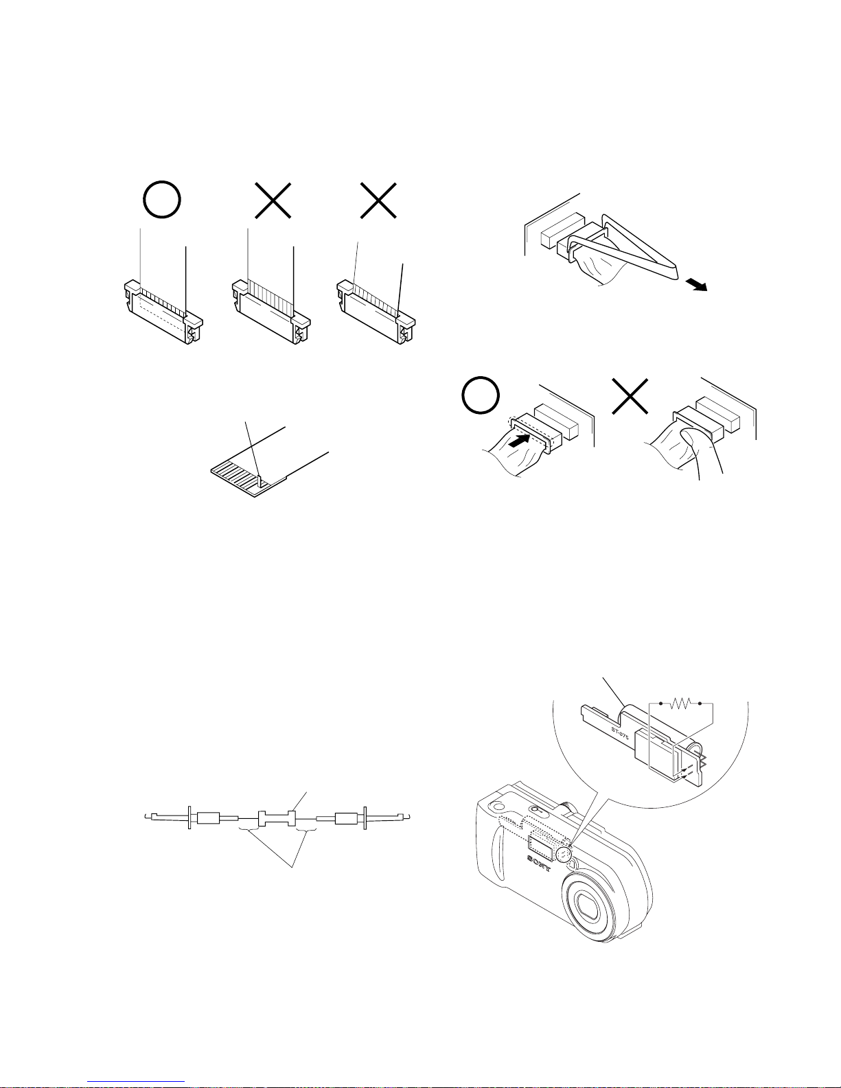
[Discharging of the ST-075 board’s charging capacitor
(C510)]
The charging capacitor (C510) of the ST-075 board is charged up
to the maximum 300 V potential.
There is a danger of electric shock by this high voltage when the
battery is handled by hand. The electric shock is caused by the
charged voltage which is kept without discharging when the main
power of the unit is simply turned off. Therefore, the remaining
voltage must be discharged as described below.
Preparing the Short Jig
To preparing the short jig, a small clip is attached to each end of a
resistor of 1 kΩ /1 W (1-215-869-11).
Wrap insulating tape fully around the leads of the resistor to prevent electrical shock.
1 kΩ/1 W
Wrap insulating tape.
Discharging the Capacitor
Short-circuit between the positive and the negative terminals of
charged capacitor with the short jig about 10 seconds.
SERVICE NOTE
• NOTE FOR REPAIR
Make sure that the flat cable and flexible board are not cracked of
bent at the terminal.
Do not insert the cable insufficiently nor crookedly.
Cut and remove the part of gilt
which comes off at the point.
(Be careful or some
pieces of gilt may be left inside)
When remove a connector, don’t pull at wire of connector.
It is possible that a wire is snapped.
When installing a connector, don’t press down at wire of connector.
It is possible that a wire is snapped.
R:1 kΩ/1 W
(Part code:
1-215-869-11)
Capacitor
– 6 –
DSC-P71/P71M
Display Code
C:32:ss
C:13:ss
E:61:ss
E:91:ss
Countermeasure
Turn the power off and on again.
Format the “Memory stick”.
Insert a new “Memory Stick”.
Checking of lens drive circuit.
Cause
Trouble with hardware.
Unformatted memory stick is inserted.
Memory stick is broken.
When failed in the focus and zoom
initialization.
Abnormality when flash is being
charged.
Checking of flash unit or replacement
of flash unit.
Caution Display During Error
SYSTEM ERROR
FORMAT ERROR
MEMORY STICK ERROR
—
[Description on Self-diagnosis Display]
Self-diagnosis display
• C: ss: ss
You can reverse the camera malfunction yourself. (However , contact your Sony dealer or local
authorized Sony service facility
when you cannot recover from
the camera malfunction.)
• E: ss: ss
Contact your Sony dealer or local authorized Sony service facility.
Battery pack was installed or removed
when using the AC adaptor.
Turn the power off and on again.
Insert a battery pack correctly. Battery pack is not inserted correctly.
E:92:ss
1-1
DSC-P71/P71M
SECTION 1
GENERAL
This section is extracted from
DSC-P31/P71 instruction manual.
2
To prevent fire or shock hazard, do
not expose the unit to rain or
moisture.
If you have any questions about this product,
you may call:
Sony Customer Information Services Center
1-800-222-SONY (7669)
The number below is for the FCC related
matters only.
CAUTION
You are cautioned that any changes or
modifications not expressly approved in this
manual could void your authority to operate
this equipm en t.
WARNING
For the Customers in the U.S.A.
This symbol is intended to
alert the user to the presence
of uninsulated “dangerous
voltage” within the product’s
enclosure that may be of
sufficient magnitude to
constitute a risk of electric
shock to persons.
This symbol is intended to
alert the user to the presence
of important operating and
maintenance (servicing)
instructions in th e lite ratu re
accompanying the appliance.
Declaration of Conformity
Trade Name: SONY
Model No.: DSC-P31
Responsible Party:Sony Electronics Inc.
Address: 680 Kinderkamack
Road, Oradell, NJ
07649 USA
Telephone No.: 201-930-6972
This device complies with Part 15 of the
FCC Rules. Operation is subject to the
following two conditions: (1) This device
may not cause harmful interference, and
(2)this device must accept any interference
received, including interference that may
cause undesired operation.
Declaration of Conformity
Trade Name: SONY
Model No.: DSC-P71
Responsible Party:Sony Electronics Inc.
Address: 680 Kinderkamack
Road, Oradell, NJ
07649 USA
Telephone No.: 201-930-6972
This device complies with Part 15 of the
FCC Rules. Operation is subject to the
following two conditions: (1) This device
may not cause harmful interference, and
(2)this device must accept any interference
received, including interference that may
cause undesired operation.
3
Note:
This equipment has been tested and found to
comply with the lim its fo r a C la ss B d ig ital
device, pursuant to Part 15 of the FCC Rules.
These limits are designed to provide
reasonable protection against harmful
interferenc e in a re sid e n tia l in stalla tio n . T h is
equipment generates, uses, and can radiate
radio frequency energy and, if not installed
and used in accordance with the instructions,
may cause harmful interference to radio
communications. However, there is no
guarantee that interference will not occur in a
particular installation. If this equipment does
cause harmful interference to rad io or
television reception, which can be determined
by turning the equipment off and on, the user
is encouraged to try to correct the interference
by one or more of the following measures:
—Reorient or relocate the receiving antenna.
—Increase the separation between the
equipment and receiver.
—Connect the equipment into an outlet on a
circuit different from that to which the
receiver is connected.
—Consult the dealer or an experienced
radio/TV technician for help.
The supplied interface cable must be used
with the equipment in order to comply with
the limits fo r a digital device pursuant to
Subpart B of Part 15 of FCC Rules.
RECYCLING NICKEL-METAL
HYDRIDE BATTERIES
Nickel-metal hydride batteries
are recyclable.
You can help preserve our
environment by returning your
used rechargeable batteries to the
collection and recycling location nearest you.
For more information regardin g re c y clin g o f
rechargeable batteries, call toll free
1-800-822-8837, or
visit http://www .rbrc.org/.
CAUTION
TO PREVENT ELECTRIC SHOCK, DO NOT
USE THIS POLARIZED AC PLUG WITH AN
EXTENSION CORD, RECEPTACLE OR
OTHER OUTLET UNLESS THE BLADES
CAN BE FULLY INSERTED TO PREVENT
BLADE EXPOSURE.
A moulded plug complying with BS 1363 is
fitted to this equipment for your safety and
convenience.
Should the fuse in the plug supplied need to be
replaced, a 5 AMP fuse approved by ASTA or
BSI to BS 1362, (i.e. marked with or
mark) must be used.
If the plug supplied with this equipment has a
detachable fuse cover, be sure to attach the
fuse cover after you change the fuse. Never
use the plug without the fuse cover. If you
should lose the fuse cover, please contact your
nearest Sony service station.
Directive:EMC Directive 89/336/EEC,
92/31/EEC
This equipment complies with the EM C
regulations when used under the following
circumstances:
•Residential area
•Business district
•Light-industry district
(This equipment complies with the E MC
standard regulations EN55022 Class B.)
For the Customers in the U.S.A.
and Canada
CAUTION:
To reduce the risk of hazards, use only
USA/UL Certified power supply cord set,
cord is Type SPT-2 or heavier, minimum
NO.18 AWG copper, one end is provided
with a moulded-on male attachment plug
cap (with a specified NEMA
configuration), and the other end is
provided with a moulded-on female
connector body (with a specified IEC nonindustrial type configuration).
NOTICE FOR THE
CUSTOMERS IN THE UNITED
KINGDOM
For the Customers in Germany

1-2
DSC-P71/P71M
4
This product has been tested and found
compliant with the limits sets out on the EMC
Directive for using connection cables shorter
than 3 mete rs.
The electromagnetic fields at the specific
frequencies may influence the picture and
sound of this camera.
For the Customers in the U.S.A.
and Canada
THIS CLASS B DIGIT AL DEVICE
COMPLIES WITH PART 15 OF THE FCC
RULES AND THE CANAD IAN ICES-003
OPERA TION IS SUBJECT TO THE
FOLLOWING TWO CONDITIONS:
(1) THIS DEVICE MA Y NOT CAUSE
HARMFUL INTERFERENCE, AND
(2)THIS DEVICE MUST ACCEPT ANY
INTERFERENCE RECEIVED,
INCLUD ING INTE RFE REN CE T HAT MAY
CAUSE UNDESIRED OPERATION.
Attention for the Customers in
Europe
Attention
“Memory Stick”
N50
5
Before using your camera
Trial recording
Before you record one-time events, you may
want to make a trial recording to make sure
that the camera is working correctly.
No compensation for contents of the
recording
Contents of the recording cannot be
compensated for if recording or playback is
not possible due to a malfunction of your
camera or recording medium, etc.
Notes on image data compatibility
•This camera conforms with the Design Rules
for Camera File Systems universal standard
established by the JEITA (Japan Electronics
and Information Technology Industries
Association).
•Playback of images recorded with your
camera on other equipment and playback of
images recorded or edited with other
equipment on your camera are not
guaranteed.
Precaution on copyright
Television programs, films, video tapes, and
other materials may be copyrighted.
Unauthorized recording of such materials may
be contrary to the provision of the copyright
laws.

1-3
DSC-P71/P71M
6
Do not shake or strike the camera
In addition to malfunctions and inability to
record images, this may render the “Memory
Stick” unusable or image data breakdown,
damage or loss may occur.
LCD screen, LCD finder (only models
with a finder) and lens
•The LCD screen and the LCD finder are
manufactured using extremely highprecision technology so over 99.99% of the
pixels are operational for effective use.
However, there may be some tiny black
points and/or bright points (white, red, blue
or green in color) that constantly appear on
the LCD screen and the LCD finder. These
points are normal in the manufacturing
process and do not affect the recording in
any way .
•Be careful when placing the camera near a
window or outdoors. Exposing the LCD
screen, the finder or the lens to direct
sunlight for long periods may cause
malfunctions.
Do not get the camera wet
When taking pictures outdoors in the rain or
under similar conditions, be careful not to get
the camera wet. If moisture condensation
occurs, see page 99 and follow the
instructions on how to remo v e it before using
the camera.
7
The auto zoom lens (for the DSC-P71
only)
This camera is equipped with an auto zoom lens.
Be careful not to bump the lens, and be careful
not to apply force to it.
On illustrations
Illustrations used in this manual are of the DSCP71 unless noted otherwise.
The pictures used in this manual
The photographs used as examples of pictures in
this manual are reproduced images, and are not
actual images shot using this camera.
Trademarks
• “Memory Stick,” , “MagicGate Memory
Stick,” and , are trademarks of Sony
Corporation.
• is a trademark of Sony
Corporation.
• Microsoft and Windows are registered
trademarks of the U.S. Microsoft Corporation
in the United States and other countries.
• Macintosh, Mac OS, and QuickTime, are
trademarks or registered trademarks of Apple
Computer, Inc.
• In addition, system and product names used in
this manual are, in general, trademarks or
registered trademarks of their respective
developers or manufacturers. However, the
™
or ® marks not used in all cases in this manual.
1-4
DSC-P71/P71M
10
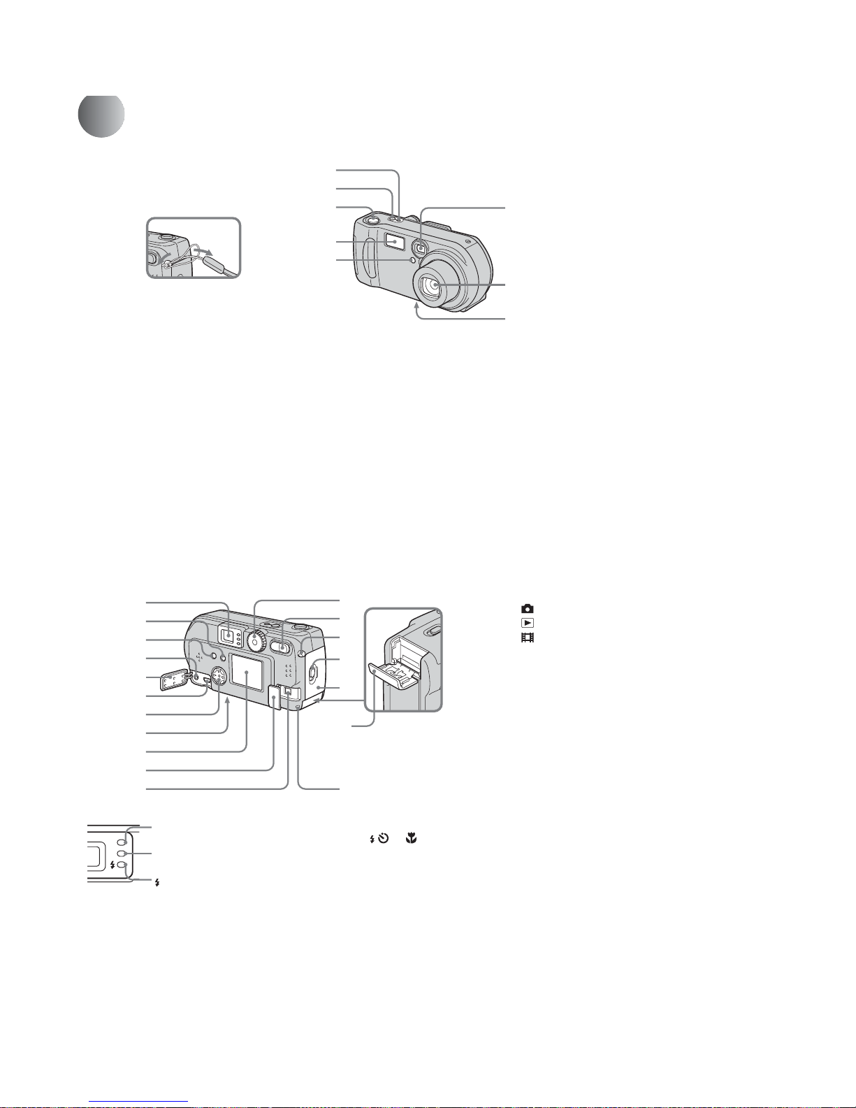
Identifying the parts (DSC-P71)
A POWER ON/OFF lamp (20)
B POWER button (20)
C Shutter button (26)
D Flash (30)
E Self-timer lamp (29)/
AF illuminator (31, 97)
F Finder window
G Lens
H Tripod receptacle (bottom
surface)
• Use a tripod with a screw length of less than
5.5mm (7/32 inch). You will be unable to
firmly secure the camera to tripods having
longer screws, and may damage the camera.
6
7
8
1
2
3
4
5
Attaching
the strap
11
A Finder
B DISPLAY/LCD ON/OFF button
(32)
C MENU button (24)
D VIDEO OUT jack (38)
E Jack cover
F USB jack (47)
G Control button
(Menu on) (v/V/b/B/z) (20)/
(Menu off) ( / /7/) (27, 29, 30)
H RESET button (bottom surface)
(82)
I LCD screen
J DC IN jack cover (19)
K DC IN jack (19)
L Mode dial (21)
: To shoot still images
: To view or edit images
: To shoot mo vies /Clip Motion
images/Multi Burst mode images
SET UP: To set the SET UP items
SCN: To shoot in the SCENE
SELECTION mode
M Zoom button (for shooting) (28)/
Index button (for viewing) (37)
N Wrist strap hook
O Open lever
P Battery cover
Q “Memory Stick” cover
R Access lamp (23)
qh
qj
qg
qk
qd
qf
q
s
1
2
3
4
5
6
7
8
9
q;
qa
Self-timer/recording
lamp (red)
AE/AF lock lamp
(green)
Flash charge lamp
(orange) (30)

1-5
DSC-P71/P71M
14
Preparing batteries
Use the following batteries in this camera.
Acceptable batteries
R6 (size AA) Nickel-Metal Hydride
batteries (2)
– NH-AA-DI (2) (supplied)
– NH-AA-2DI twin-pack (recommended, not
supplied)
Batteries that cannot be used
Manganese batteries, lithium batteries, nicad batteries, alkaline batteries (cannot be
used with the DSC-P71)
* Use of AA alkaline batteries may result in
shorter than desired operating time. (only in the
DSC-P31)
When alkaline batteries are used, take note of
the following information.
• Turn POWER SAVE “ON”, shut the LCD
screen off, and use the Finder to shoot your
images. This will lengthen battery life
(page 16).
• There is a big difference in the performance
of batteries of different types and of batteries
made by different manufacturers. This is
especially true in low temperatures, where
some batteries are noticeably weaker.
You may not be able to shoot in temperatures
below +5°C (41°F).
• The battery remaining indicator may not
display the correct information.
Charging the batteries
,
Insert Nickel-Metal Hydride
batteries into the charger
(supplied).
• Be sure to charge the Nickel-Metal Hydride
batteries supplied with your camera before
using them.
• Be sure to charge the batteries in an
environment where the ambient temperature is
10°C to 30°C (50°F to 86°F). If the batteries are
charged in an environment where the
temperature is outside that range, the batteries
may not charge efficiently.
• Connect the battery charger to an easily
accessible wall outlet (mains) close by. If
something goes wrong while you are using the
charger, immediately shut off the power by
pulling the plug out of the wall outlet.
1
BC-CS1 (supplied)
Insert with the correct polarity +/−
, Connect the charger to a wall
outlet (mains) using the power
cord (mains lead).
Charging starts, and the charge lamp lights.
When the charge lamp goes out, charging is
finished.
• When charging is finished, disconnect the
power cord (mains lead) from the wall outlet
(mains), and remove the Nickel-Metal Hydride
batteries from the charger.
• When transporting the Nickel-Metal Hydride
batteries, be sure to use the battery case
(supplied). If the +/− metal terminals are
shorted, there is a possibility of danger from
excessive heat or fire.
2
To the wall outlet
(mains)
Power cord
(mains lead)
Charge
lamp
Getti
ng starte
d
15
Getting started
Charging the Nickel-Metal
Hydride batteries
• If the poles of the Nickel-Metal Hydride
batteries are dirty, the batteries may not
charge properly. Occasionally clean the poles
of the batteries and the terminals of the
charger by wiping them with a dry cloth.
• At the time of purchase, or when the Nickel-
Metal Hydride batteries haven’t been used for
a long time, they may not fully charge. This is
typical of this type of battery, and is not a
malfunction. If this happens, repeatedly using
up the battery fully, and then recharging it,
should correct the problem.
• Even when Nickel-Metal Hydride batteries
are not being used they loose their charge
naturally over time. It is recommended that
you recharge the batteries just before using
them.
• If you recharge Nickel-Metal Hydride
batteries before fully using up the existing
charge, the so-called memory effect* can
occur, and the low battery warning will be
triggered sooner than expected. Charging the
battery after fully depleting the existing
charge should correct the problem.
* The “memory effect” – the situation in
which a battery temporarily accepts a less
than full charge.
•To use up the batteries completely, put
the camera in “SLIDE SHOW” mode
and leave it that way until the batteries
are used up (page 67).
Precautions to be observed
when charging the batteries
• Do not charge any other batteries except Son y
Nickel-Metal Hydride batteries in the charger
supplied with your camera. If you try to
charge any other type of battery (e.g.,
manganese batteries, alkaline dry cells, or
one-time lithium batteries) than the batteries
specified, those batteries may leak, overheat,
or explode, causing the danger of burns or
other injuries.
• Be sure to charge both Nickel-Metal Hydride
batteries at the same time.
• When the batteries are charged, use them only
in an environment where the temperature
range is 0°C to 40°C (32°F to 104°F).
Otherwise, there is a danger of leaks,
explosions, excessive heat, fire, or electric
shock.
• Do not charge fully charged Nickel Metal
Hydride batteries again. Otherwise, there is a
danger of leaks, explosions, excessive heat,
fire, or electric shock.
• Do not peel off the external seals or damage
the batteries. Never use batteries from which
the seals have been partially or completely
removed, or batteries that have been split in
any way.
Charging time
This represents the time required to charge
fully depleted Nickel-Metal Hydride
batteries using the supplied BC-CS1
charger in an environment where the
ambient temperature is 25°C (77°F).
• Charging is complete in approximately 13
hours. The charge lamp may remain lit longer
than 13 hours, but this is not a malfunction.
• If you use the ACC-CSNQ STAMINA “Super
Quick charge” kit (not supplied), the batteries
will charge faster.
Nickel-Metal
Hydride battery
Charging time
NH-AA-DI × 2
(supplied)
Approx. 13
hours
1-6
DSC-P71/P71M
16
Charging the Nickel-Metal hydride batteries (continued)
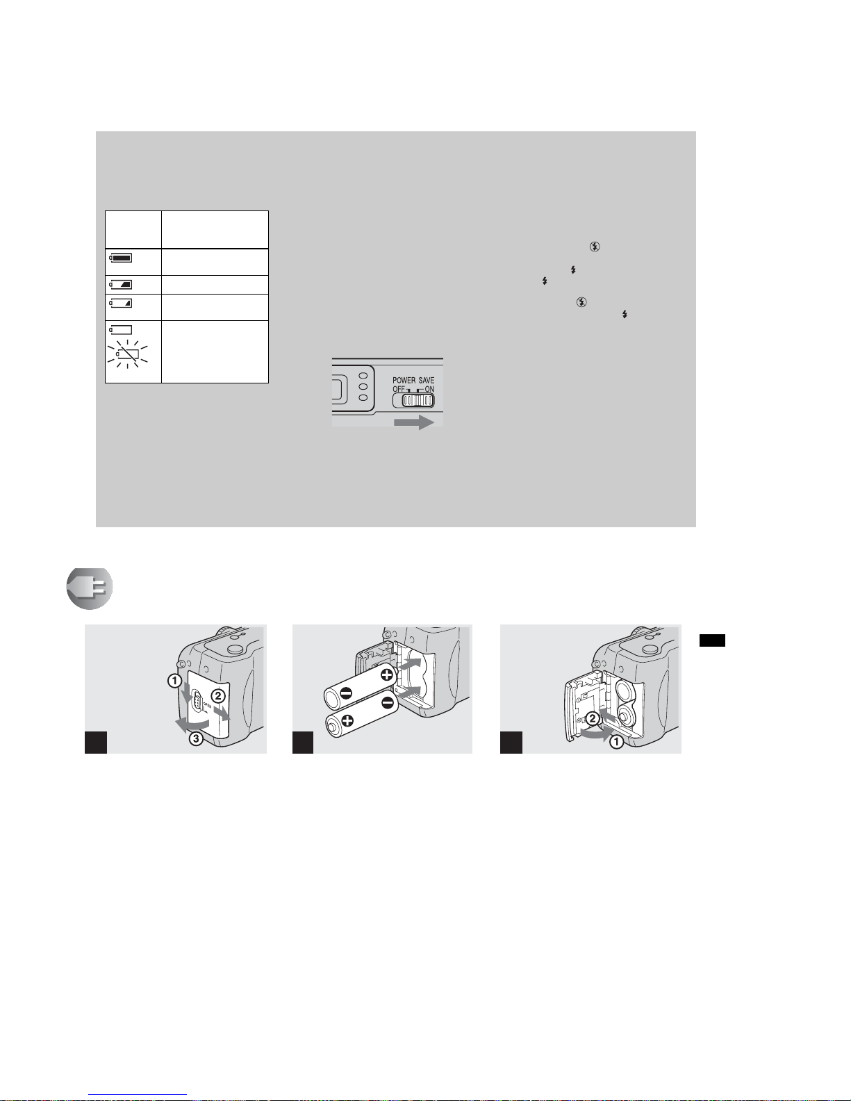
Battery remaining indicator
As the battery power decreases with use,
the Battery remaining indicator displays
the amount of power remaining using the
following symbols.
• If the LCD screen is off, press the DISPLAY/
LCD ON/OFF button to turn it on.
• Based on the conditions under which the
camera is being used and the state of the
charge, or on the environment, this
information may not be correctly indicated.
• When the AC adaptor is being used, the
Remaining battery information is not
displayed.
The POWER SAVE function
When the POWER SAVE function is set
to ON, you can shoot for a longer period of
time.
DSC-P71
Turn the Mode dial to SET UP, and set
“POWER SAVE” in “SETUP 2” to “ON”.
When the camera is shipped from the
factory, this item is set to “ON” (page 98).
DSC-P31
Set the POWER SAVE switch to ON.
When the camera is shipped from the
factory, this switch is set to ON.
When the POWER SAVE function is
ON
• The LCD screen will be darker than it is when
POWER SAVE is set to OFF. You cannot
change the settings for “LCD BACKLIGHT”
at this time (page 98). To make the available
shooting time even longer, it is recommended
that you turn off the LCD screen and use the
Finder to do your shooting (page 32).
• In Flash mode, the “ ” (No flash) is
displayed. If you want to shoot using the
flash, press v ( ) on the control button, and
select “ ” (forced flash) or Auto (page 30).
• When the power turns on, the Flash mode is
normally set to “ ” (No flash).
• When the flash is charging (“ ” the Flash
charge lamp blinks), the LCD screen turns
off.
• In shooting still images, the focus only
focuses when the shutter is pushed down
halfway.
Battery
remaining
indicator
Battery remain ing
guidelines
(A full charge is 100%)
Sufficient power
remaining
Battery half full
Battery low, recording/
playback will stop soon.
Flashing
Change the batteries for
fully charged ones, or
charge these batteries.
17
Getting started
Inserting the batteries
, Open the Battery cover.
Slide it in the direction of the arrow, and it
opens out.
, Insert the batte ries.
Match the
+/−
poles of the batteries to the
+
/
−
marks inside the battery case.
• Occasionally clean the poles of the batteries
and the terminals of the Battery cover by
wiping them with a dry cloth. If the poles of the
batteries or the terminals become covered with
a film of dirt or oil from the skin, the operating
time of the camera can be greatly reduced.
, Close the Battery cover.
Close the Battery cover while holding the
batteries in. Make sure the cover is closed
securely.
To remove the batteries
Stand the camera on end, open the Battery
cover upward, then remove the batteries.
• Make sure you don’t drop the batteries when
opening or closing the Battery cover.
1 2 3
1-7
DSC-P71/P71M
18
Inserting the batteries (continued)
Battery life and the number of
images that can be recorded/
played back
The tables show approximate guidelines
for the length of time the camera can be
used when picture quality is set to
Standard, when you shoot in Flash mode
“”, and when you shoot in Normal
mode in an environment where the
ambient temperature is 25°C (77°F), and
the supplied Nickel-Metal Hydride
batteries are fully charged. The guidelines
for the number of images that can be
recorded or played back allow for
changing the “Memory Stick” as
necessary. Actual results may differ
slightly from these, depending on the
conditions of use.
When shooting* still images
DSC-P71
DSC-P31
* Recording one image every three seconds
When playing back** still images
DSC-P71
DSC-P31
**With the LCD screen on, showing single
images in order, one approximately every
three seconds
Recording*** movies images
*** Continuous recording with a picture size of
160×112
Image
size
R6 (size AA) Ni-MH (2) (supplied)
LCD
screen
Battery
life (min.)
No. of
images
2048×1536
ON Approx. 90 Approx. 1800
OFF Approx. 120 Approx. 2400
640×480
ON Approx. 90 Approx. 1800
OFF Approx. 120 Approx. 2400
Image
size
R6 (size AA) Ni-MH (2) (supplied)
LCD
screen
Battery
life (min.)
No. of
images
1600×1200
ON Approx. 120 Approx. 2400
OFF Approx. 150 Approx. 3000
640×480
ON Approx. 120 Approx. 2400
OFF Approx. 150 Approx. 3000
Image size
R6 (size AA) Ni-MH (2 )
(supplied)
Battery life
(min.)
No. of images
2048×1536 Approx. 230 Approx. 4600
640×480 Approx. 230 Approx. 4600
Image size
R6 (size AA) Ni-MH (2 )
(supplied)
Battery life
(min.)
No. of images
1600×1200 Approx. 280 Approx. 5600
640×480 Approx. 280 Approx. 5600
R6 (size AA) Ni-MH (2 )
(supplied)
LCD screen
ON (min.)
LCD screen
OFF(min.)
DSC-P71 Approx. 120 Approx. 170
DSC-P31 Approx. 150 Approx. 200
19
Getting started
Using an external power source
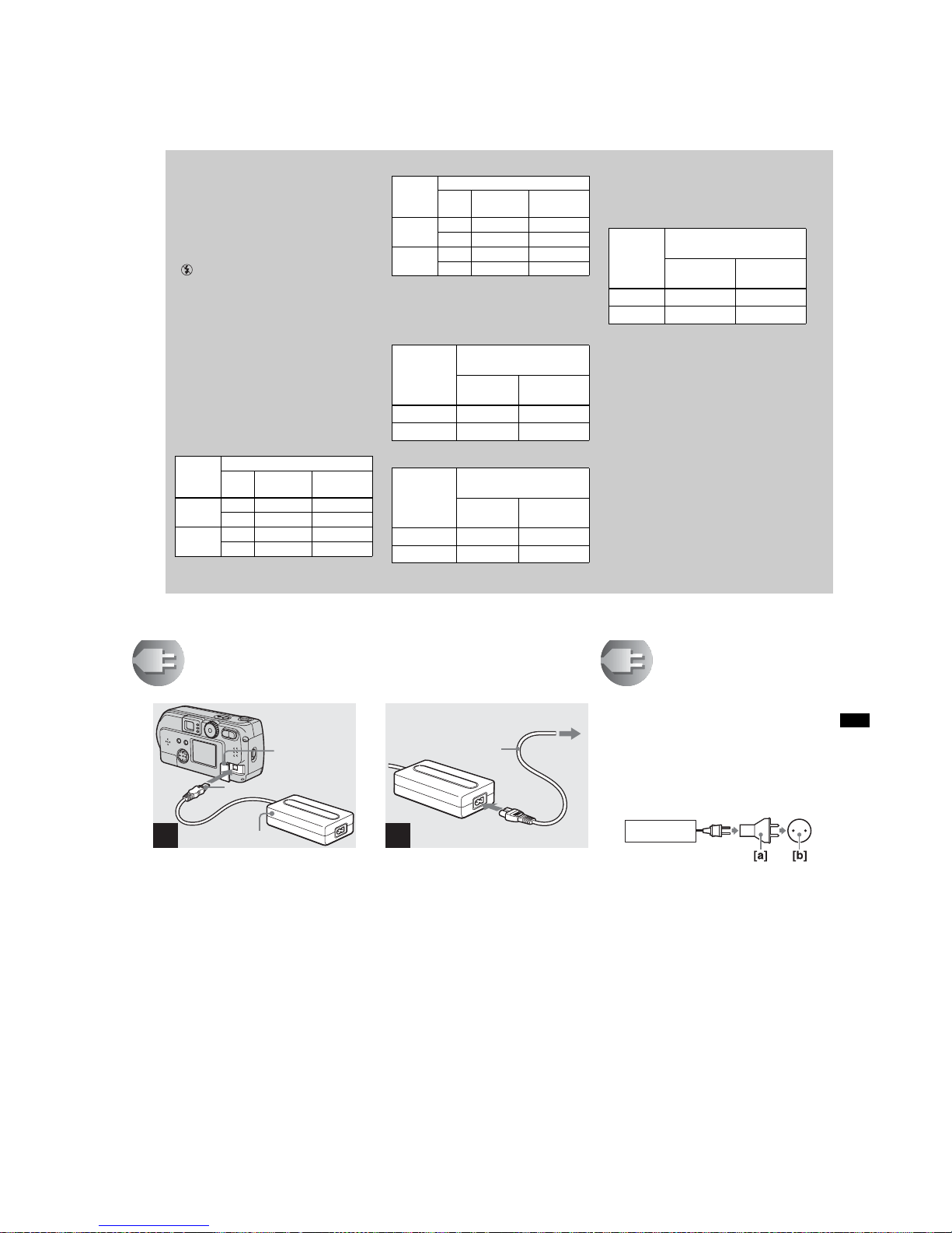
, Open the DC IN jack cover,
then connect the AC-LS1 AC
power adaptor (not supplied)
to the DC IN jack of the ca mera .
Connect the cable with the v mark facing
up.
• Connect the AC power adaptor to an easily
accessible wall outlet (mains) close by. If
something goes wrong while you are using the
adaptor, immediately shut off the power by
pulling the plug out of the wall outlet.
1
DC IN jack
cover
AC power adaptor
(
not supplied
)
DC plug
, Connect the power cord (mains
lead) to the AC power adaptor
and to the wall ou tle t (mains).
• When you have finished using the AC power
adaptor, disconnect it from the DC IN jack of
the camera.
• To use power from an automobile, use a DC
adaptor/Charger (not supplied).
• If you insert or remove the DC plug while you
are using the batteries, the power may shut off.
2
2 To the wall outlet (mains
)
Power cord
(mains lead)
1
Using your camera
abroad
Power sources
You can use your camera in any country or
area with the supplied battery charger
within 100 V to 240 V AC, 50/60 Hz. Use a
commercially available AC plug adaptor
[a], if necessary, depending on the design of
the wall outlet (wall socket) [b].
BC-CS1
1-8
DSC-P71/P71M
20
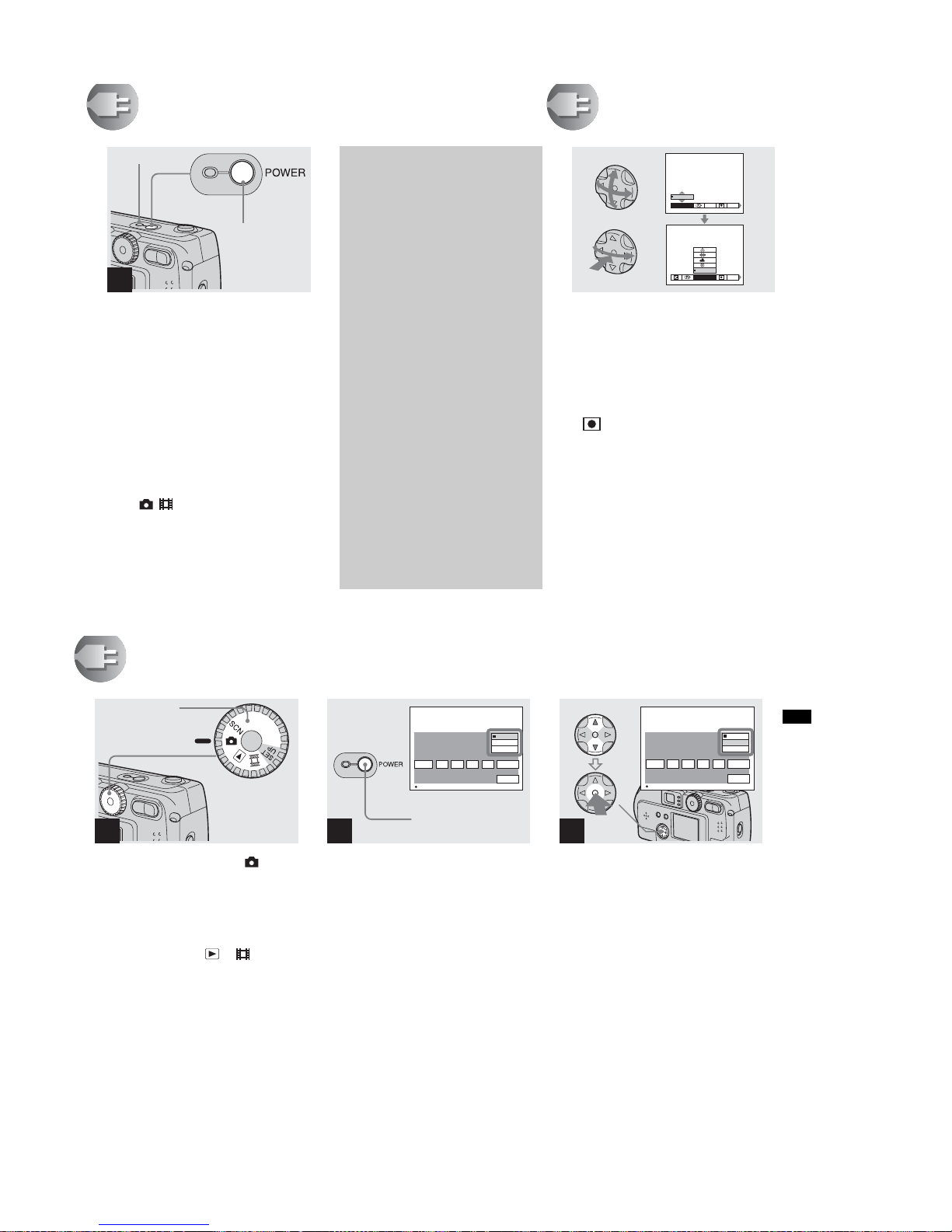
Turning on/off your camera
, Press the POWER button.
The POWER ON/OFF lamp lights in green,
the power is on, and the lens cover opens.
When you turn on your camera for the first
time, the “CLOCK SET” screen appears
(see the next page).
To turn off the power
If you press the POWER button again, the
POWER ON/OFF lamp goes out, and the
camera turns off.
• if you turn the power on when the Mode dial is
set to , , or SCN, the lens begins to move
(DSC-P71 only). Please be careful not to touch
the lens.
1
POWER button
POWER ON/
OFF lamp
The Auto Power Off feature
If no tasks are performed for a while*
when shooting, playing back, or
performing SET UP while using the
batteries, power is automatically shut
off to preserve battery power.
However, in the following
circumstances, even if the battery is
being used to power the camera, the
Auto Power Off feature will not work.
•Movies are being played back
•A slide show is being shown
•There is a plug in the USB terminal
or the VIDEO OUT jack
* When POWER SAVE is set to ON:
approximately 90 seconds
When POWER SAVE is set to OFF:
approximately 3 minutes
How to use the
control button
To change the current settings of the
camera, bring up the menu or SET UP on
the LCD screen (page 55), and use the
control button to make the changes.
For each item, press v/V/b/B to select the
desired value, then press the center z or
b/B to make the setting.
• (Spot light-metering) is not displayed on
the menu of the DSC-P31 (page 61).
WHITE BAL
AUTO
ISO
WB
EV
ISO
0EV
0EV
21
Getting started
Setting the date and time
, Turn the Mode dial to .
• To change values for the time and the date that
have been previously set, change the Mode dial
to SET UP, choose “CLOCK SET” in “SETUP
1” (page 97), then proceed from Step 3.
• You can also carry out this operation when the
mode dial is set to SCN, , or .
, Press the POWER button.
The POWER lamp lights in green and the
“CLOCK SET” screen appears.
, Choose the desired order for
the date, the month and the
year using v/V on the control
button, then push the center z.
You can choose from “Y/M/D” (year/
month/day), “M/D/Y”, and “D/M/Y”.
• If the rechargeable button battery, which
provides the power for saving the time data,
ever loses its charge (page 99), the “CLOCK
SET” screen automatically reappears. If this
happens, reset the date and time by following
the above procedure, starting from Step 3.
1
Mode dial
2
D/M/Y
OK
CANCEL
M/D/Y
Y/M/D
CLOCK SET
2002
/:
/
1
1
12 02
AM
OK
POWER button
3
D/M/Y
OK
CANCEL
M/D/Y
Y/M/D
CLOCK SET
2002
/:
/
1
1
12 02
AM
OK
1-9
DSC-P71/P71M
22
Setting the date and time (continued)
, Choose the year, month, day,
hour, and minute items using
b/B.
A v will be shown above, and a V will be
shown below the item currently selected to
be set.
, Set the desired numerical
value using v/V on the control
button, then press the center
z.
After setting the current numerical value,
move to the next item. Repeat the above
process until all of the items have been set.
• If you choose “D/M/Y” in Step 3, use the 24
hour clock display.
, Choose “OK” using the B on
the control button, and then
press the center z.
After the date and time are set, the clock
will start to keep time.
• To abort the setting process, choose
“CANCEL”, and press the center z.
4
D/M/Y
OK
CANCEL
M/D/Y
Y/M/D
CLOCK SET
2002
/:
/
1
1
12 02
AM
OK
5
D/M/Y
OK
CANCEL
M/D/Y
Y/M/D
CLOCK SET
2002
/:
/
1
7
12 02
AM
OK
D/M/Y
OK
CANCEL
M/D/Y
Y/M/D
CLOCK SET
2002
/:
/
4
7
10 30
PM
OK
6
23
Shooting still images
Inserting and removing a “Memory Stick”
, Open the “Memory Stick”
cover.
Slide the cover in the direction of the arrow
to open it.
, Insert the “M em ory Stick.”
Holding the “Memory Stick” as shown in
the illustration, insert it all the way in until
it clicks.
• Whenever you insert a “Memory Stick,” push it
all the way in until it clicks. If you do not insert
it correctly, a message such as “MEMORY
STICK ERROR” will be displayed on the LCD
screen.
, Close the ”Memory Stick”
cover.
To remove a “Memory Stick”
Open the “Memory Stick” cover, then push
the “Memory Stick” to pop it out.
•Whenever the Access lamp is lit, the
camera is recording or reading out an
image. Never remove the “Memory
Stick” or turn off the power at this time.
1
Bottom
2
Label side
Connector
side
3
Access
lamp
Shooti
ng s
till i
mages

1-10
DSC-P71/P71M
24
Deciding the still image size and image quality
, Turn the Mode dial to , turn
on the power, and then push
the MEN U button.
The menu appears.
• You can also carry out this operation when the
mode dial is set to SCN.
• (Spot light-metering) is not displayed on
the menu of the DSC-P31 (page 61).
, Select “ ” (Image size) using
b/B on the control button. Use
v/V to selec t the desired image
size.
The image size is set.
, Select “ ” (Image quality)
using b/B on the control
button. Use v/V to s ele c t th e
desired image quality.
The image quality is set.
When the setting is completed, press the
MENU button. The menu disappears from
the screen.
• For image quality, you can choose either
“FINE” or “STANDARD”.
• The image size and quality values chosen here
will be preserved even when the camera is
turned off.
1
WHITE BAL
AUTO
ISO
Menu button
2
IMAGESIZE
640 x 480
1280 x 960
1600x1200
2048 (3 : 2)
2048x1536
SO
IMAGE SIZE
640 x 480
1280 x 960
1600 (3 : 2)
1600x1200
DSC-P71 DSC-P31
3
PFX
MODE
FINE
P.QUALITY
STANDARD
FINE
25
Shooting still images
Image size and quality
You can choose image size (number of
pixels) and image quality (compression
ratio) based on the kind of images you
want to shoot. The larger you make the
image size and the higher you make the
image quality, the better your image, but
also the larger the amount of data needed
to preserve your image. This means you
can save fewer images in your “Memory
Stick.”
Choose an image size and quality level
appropriate for the kind of images you
want to shoot.
You can resize the images later (Resize
function, see page 71).
You can choose image size from among
the six options in the following tables.
Image size Examples
2048×1536
(DSC-P71 )
Very fine prints
2048(3:2)
(DSC-P71 )
3:2 prints
1)
1600×1200 Printing A4 size images
1600 (3:2)
(DSC-P31 )
3:2 prints
1)
1280×960 Printing postcard size images
640×480
For images to be attached to e-mail
The number of images* that can be saved in a “Memory Stick”
The number of images that can be saved in FINE (STANDARD) mode are shown below.
(Units: number of images)
* When the shooting mode is normal
For the number of images that can be saved in
other modes, see page 91.
Capacity
8MB 16MB 32MB 64MB 128MB
Image size
2048×1536
(DSC-P 7 1)
5 (9) 10 (18) 20 (36) 40 (72) 80 (144)
2048(3:2)
(DSC-P71)
5 (9) 10 (18) 20 (36) 40 (72) 80 (144)
1600×1200 8 (15) 16 (30) 32 (60) 64 (120) 128 (240)
1600 (3:2)
(DSC-P 3 1)
8 (15) 16 (30) 32 (60) 64 (120) 128 (240)
1280×960 12 (22) 24 (44) 50 (93) 100 (186) 200 (372)
640×480 48 (118) 96 (240) 195 (488) 393 (983) 786 (1966)
• The image size is the screen size used when
viewing the images on a personal computer.
When the images are viewed on the LCD
screen of the camera, they all look the same
size.
• Number of shooting images can differ from
these values according to shooting conditions.
• The image size value (e.g., 2048×1536) is the
number of pixels displayed.
For information how to shoot images to be
used as attachments to e-mail messages,
see page 65.
1)
This option records images in a horizontal to
vertical proportion of 3:2 to match the size of
the print paper used.
1-11
DSC-P71/P71M
26
Basic still image shooting (using auto adjustment mode)
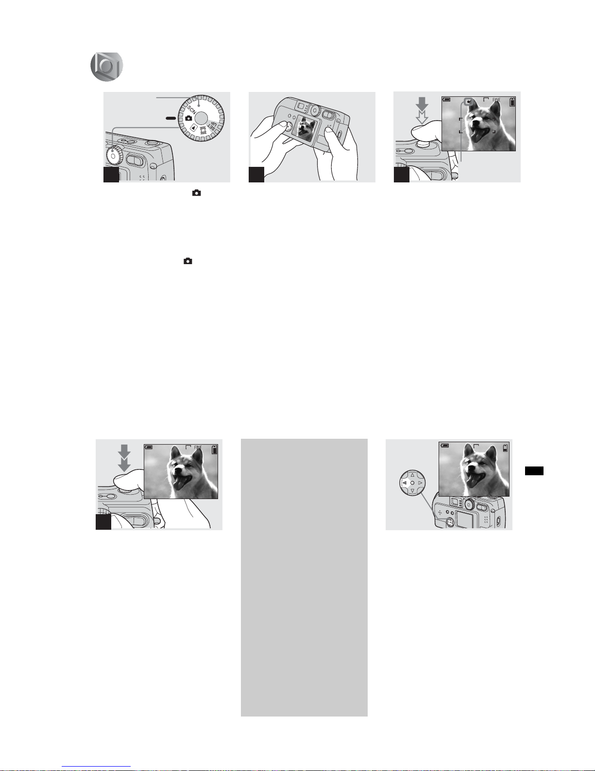
, Set the mode dia l to , and
turn on your camera.
• The lens cover opens when the power is turned
on.
• When the camera is turned on or when using
the zoom, and the lens is moving, don’t touch
the lens assembly (DSC-P71 only) (page 28).
• When the Mode dial is set to , the exposure
and focus are adjusted automatically.
• Clean the lens with a soft cloth if it is dirty
(page 99).
, Hold your camera with your
both hands and position a
subject in the center of the
frame to fo c u s o n .
Do not cover the lens or flash with your
fingers.
• You can choose either Multi-point AF mode or
Center AF as the AF mode (page 58).
, Press and hold the shutter
halfway down.
The camera beeps. When the AE/AF lock
indicator stops flashing and remains on, the
camera is ready for shooting.
• If you remove your finger from the shutter,
shooting will be canceled.
• The minimum focal distance to a subject is 50
cm (19
11
/16 inches) for the DSC-P71, and 10
cm (3
15
/16 inches) for the DSC-P31. To shoot
subjects at distances closer than this, use Macro
mode (DSC-P71 only) (page 28).
• The frame appearing on the LCD screen shows
the limits of the area where the focus will be
adjusted. (For more details on the AF range
finder, see page 58.)
1
Mode dial
2
3
2048
F2.1
50
4
Flashes in
green t Lights up
27
Shooting still images
, Press the shutter fully down.
A beeping sound is heard, the shooting is
completed, and the still image is saved in
the “Memory Stick.” When the Recording
lamp goes out, you can shoot the next
image.
• When you are shooting with the battery, if no
tasks are performed for a while* with the
camera turned on, power is automatically shut
off to preserve battery power (page20).
* When POWER SAVE is set to ON:
approximately 90 seconds
When POWER SAVE is set to OFF:
approximately 3 minutes
Checking the last shot
image (Quick Review)
, Press b (7) on the control
button.
To return to shooting mode, press the
shutter lightly or press b (7) on the control
button again.
To delete the image displayed on the
LCD screen
1 Press MENU button to display the menu.
2 Press B on the control button to select
“DELETE”, then press the center z.
3 Press v on the control button to select
“OK”, then press the center z.
The image will be deleted.
4
2048
About Auto Focus
When you try to shoot a subject that is
hard to focus on, the AE/AF lock
indicator will change to flashing
slowly.
The Auto Focus function may be
difficult to use with in the following
subjects. In such cases, release the
shutter, then try to recompose the shot
and focus again.
• The subject is distant from the camera and
dark
• The contrast of the subject and its
background is poor
• The subject is seen through glass, such as
a window
• A fast-moving subject
• The subject has a reflection, such as that
from a mirror, or there is a luminous body
and a lustrous subject
• A flashing subject.
10:30
PM
2002 7 4100-0029
6/8
REVIEW
2048
1-12
DSC-P71/P71M
28
Using the zoom feature
, Press the Zoom button to
choose the desired image size,
and shoot your image.
The minimum distance needed
to focus on a subject
DSC-P71
50 cm (19
11
/16 inches) for both W (wide
angle) and T (telephoto)
DSC-P31
10 cm (3
15
/16 inches)
• The lens moves when the zoom feature is being
used (DSC-P71 only). Be very careful not to
touch the lens.
• The zoom feature cannot be used when
shooting movies (page 83).
Shooting close-ups (Macro)
(DSC-P71 only)
For close-ups of small subjects like flowers
or insects, shoot using the Macro feature.
You can use this feature for close-ups of
subjects up to the distances specified below.
When the zoom is set all the way to
the W side: distances up to 10 cm (3
15
/16
inches) from the end of the lens
When the zoom is set all the way to
the T side: distances up to 50 cm (19
11
/16
inches) from the end of the lens
2048
4
T
W
2048
4
T
W
W (wide-angle) T (telephoto)
Digital zoom
DSC-P71
When the zoom exceeds 3x,
enlargement is carried out using digital
processing of the image. The image can
then be enlarged up to 6x using the
digital zoom feature. Because picture
quality deteriorates when digital zoom
is used, set “DIGITAL ZOOM” in SET
UP to “OFF” when this feature is not
needed (page 97).
DSC-P31
The DSC-P31 does not have an optical
zoom. It has only a 3x digital zoom.
There is no Digital zoom item in SET
UP.
• When you are using digital zoom, you
cannot confirm the image using the finder.
• When you are using the digital zoom
feature, the Auto focus frame is not
displayed.
T
W
The T side of this line shows
the extent of digital zoom
29
Shooting still images
, Turn the Mode dial to , and
press B () on the control
button.
(Macro) will appear on the LCD screen.
• If the menu is currently displayed, press the
MENU button first and the menu will
disappear.
• You can perform this operation even when the
Mode dial is set to SCN (other than Landscape
mode) (page 34), or .
, Center the subject in the frame,
and shoot the image.
To return to normal shooting
Press B () on the control button one more
time. disappears from the LCD screen.
• Use the LCD screen to shoot when using the
Macro feature. If you use the finder, the limits
of what you see and what you actually shoot
may be different.
Using the self-timer
, Turn the Mode dial to , and
press V () on the control
button.
(Self-timer) will appear on the LCD
screen.
• If the menu is currently displayed, press the
MENU button first and the menu will
disappear.
• You can also carry out this operation when the
mode dial is set to SCN, or .
1
2048
4
2
2048
1
2048
4

1-13
DSC-P71/P71M
30
, Center the subject in the frame,
and press the shutter all the
way down.
The Self-timer lamp (page 10 for the DSCP71, page 12 for the DSC-P31) will blink in
orange, and you will hear a beeping sound.
The image will be shot within
approximately 10 seconds.
To cancel the self-timer in the middle
of the operation
Press V () on the control button one more
time.
• If you stand in front of the camera and press the
shutter, the focus and the exposure may not be
correctly set.
Selecting a flash mode
, Turn the mode dial to select ,
and press v () on the control
button repeatedly to select a
flash mode.
Flash mode has the following features.
No indicator (Auto): Based on the
lighting conditions, the camera will decide
if there is enough light, and will use the
flash accordingly (factory setting).
(forced flash): The flash will be used
regardless of the amount of ambient light.
(no flash): The flash will not be used.
Each time you press the button, the display
changes as follows.
When POWER SAVE is OFF
No indicator (Auto) t (forced flash) t
(no flash)
When POWER SAVE is ON
(no flash) t No indicator (Auto) t
(forced flash)
• If the menu is currently displayed, press the
MENU button first and the menu will
disappear.
• You can change the brightness of the flash
using “FLASH LEVEL” in the settings menu
(page 93).
• When Flash mode is set to Auto or (forced
flash), and you look at the LCD screen in a dark
place, you may notice some “noise” in the
image, but this will have no effect on the image
you shoot.
• While the flash is being charged, the Flash
charging lamp blinks. When charging is
completed, the lamp goes out.
• When you press the shutter button halfway
down while the flash is flashing, ( ) the Flash
charge lamp turns on.
2
2048
F2.3
3
0EV
50
2048
4
31
Shooting still images
To reduce “red-eye” when
recording live subjects
When the flash begins to strobe before
the image is shot, the red-eye
phenomenon is reduced. In SET UP,
set “RED EYE REDUCTION” to
“ON” (page 97). “ ” will be displayed
on the LCD screen.
• The amount of red-eye reduction possible
varies according to the individual. In
addition, the distance to the subject, and
whether or not the subject has seen the
flash begin to strobe may also reduce the
effectiveness of the red-eye reduction
process.
m
Shooting with th e AF
illumina to r
This is additional lighting provided to
assist in focussing when shooting in dark
places.
Set “AF ILLUMINATOR” (page 97) in
SET UP to “AUTO”. When shooting,
“” is displayed; the AF illuminator
will flash automatically during the time
between when the shutter is pressed
halfway down and the focus locks.
• When the AF illuminator flashes, but
sufficient light does not reach the subject
(the maximum recommended distance for
this feature is 2.8m (9.2 ft.) (wide), 1.8m (5.9
ft.) (tele) in DSC-P71, 2.5m (8.2 ft.) in DSCP31, or the subject has weak contrast, the
camera may not focus properly.
• The light from the AF illuminator may miss
the center of the image somewhat, but as
long as it reaches the subject, the camera will
focus properly.
• When the focus is adjusted manually , the AF
illuminator doesn’t function.
• Under the following conditions, the AF
illuminator will not function.
– When shooting in Twilight landscape
mode
– When shooting in Landscape mode
• The AF illuminator is a bright light. There
are no safety hazards, but when shooting at
short distances, do not aim it directly at the
subject’s eyes.
ON
2048
ON
6
1-14
DSC-P71/P71M
32
Shooting with the finder
The finder is convenient when you want to
save battery power, or when it is difficult to
confirm the image using the LCD screen.
Each time you press the DISPLAY/LCD
ON/OFF button, the display changes in the
following order.
When the LCD screen display is off (only
warning messages are displayed)
• For further details on the items displayed, see
page 103.
• Just as with the AE/AF lock indicator on the
LCD screen display, when the AE/AF lock
lamp of the Finder section stops flashing and
remains lit, you can start shooting again
(page 26).
• When the LCD screen display is turned off, the
digital zoom does not function (page 28).
• When the LCD screen display is turned off, if
you press the (Flash mode)/ (Self-timer)/
(Macro, DSC-P71) or (Spot lightmetering, DSC-P31), the image will be
displayed on the screen for approximately 2
seconds so you can check or change the setting.
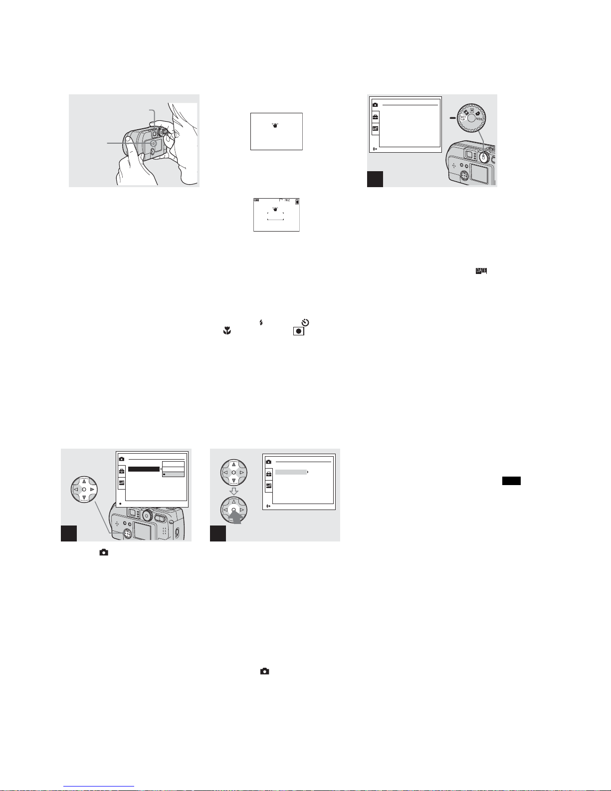
Shooting with the date and
time inserted
, Turn the mode dial to SET UP.
The SET UP menu is displayed.
• When images are shot with the date and time
inserted, the date and time cannot be removed
later.
• When shooting images with the date and time
inserted, the actual date and time are not
displayed on the LCD screen, instead, “ ” is
displayed in the upper left portion of the LCD
screen. The actual date and time are displayed
when the image is played back.
• When you have chosen a date format, you can
choose [Insert the correct date and time]
(page 21), and the information will be inserted
in the format you chose.
• The “DIGITAL ZOOM” item is not displayed
on the SET UP screen of the DSC-P31
(page 28).
Finder
DISPLAY/
LCD
ON/OFF
button
2048
4
r
LCD screen display is OFF
r
Screen display is set to ON.
1
CAMERA
MOVING IMAGE :
DATE/TIME :
DIGITAL ZOOM :
RED EYE REDUCTION :
AF ILLUMINATOR :
MPEG MOVIE
OFF
ON
OFF
OFF
SELECT
33
Shooting still images
,
Select (
CAMERA
) using
v/V
on the control button and
press
B
.
Select “
DATE/TIME
” using
v/V
and press
B.
, Choose the type of data to be
inserted using v/V on the
control button, then press the
center z.
DAY/TIME: Inserts the day and the time of
shooting into the image
DATE: Inserts the year, the month and the
date of shooting into the image
OFF: Does not insert date/time data into the
image
After the setting have been completed, turn
the mode dial to , and continue your
shooting.
• You can also carry out this operation when the
mode dial is set to SCN.
• The settings made here will be saved even
when the power is turned off.
2
CAMERA
MOVING IMAGE :
DATE/TIME :
DIGITAL ZOOM :
RED EYE REDUCTION :
AF ILLUMINATOR :
DAY&TIME
DATE
OFF
OK
3
CAMERA
MOVING IMAGE :
DATE/TIME :
DIGITAL ZOOM :
RED EYE REDUCTION :
AF ILLUMINATOR :
MPEG MOVIE
Y/M/D
ON
OFF
OFF
SELECT
1-15
DSC-P71/P71M
34
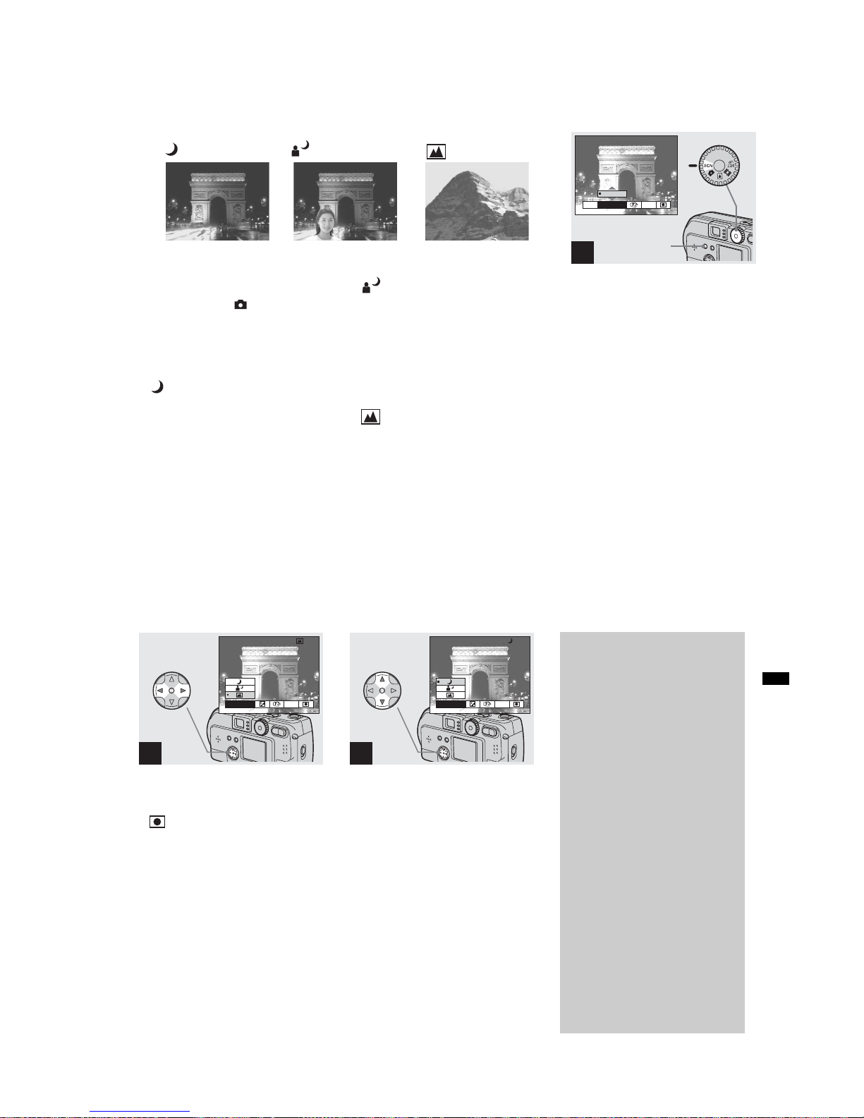
Shooting according to scene conditions
(SCENE SELECTION)
Ordinarily shoot with the camera set to set
to Auto (Mode dial: ), but when shooting
at night, shooting people at night , or
shooting landscapes, use the modes listed
below to increase the quality of your
images.
Twilight mode
Under dark lighting conditions, you can
shoot using the Twilight mode, and still get
good images. However, because the shutter
speed is slower under these conditions, we
recommend you use a tripod.
• The flash cannot be used.
Twilight portrait mode
Use this mode when shooting people in the
foreground at night.
Because the shutter speed is slow, it is
recommended that you use a tripod.
• Allows you to shoot images of people in the
foreground with distinct outlines without losing
the feeling that you are shooting at night.
• The flash can be used.
Landscape mode
Focuses on images far away, so is
convenient for shooting landscapes at a
distance.
• You cannot shoot in Macro mode.
, Turn the mode dial to SCN, and
press the MENU button.
The menu appears.
Twilight mode
Twilight portrait mode
Landscape mode
1
WB
EVSCN
0EV
0EV
MENU button
35
Shooting still images
, Select “SCN” using b/B on the
control button.
• (Spot light-metering) is not displayed on
the menu of the DSC-P31 (page 61).
, Select the desired mode using
v/V on the control button.
The mode will be set to your choice.
When the setting is completed, press the
MENU button. The menu disappears from
the screen.
• When you cancel Scene selection, set the mode
dial to something other than SCN.
• The settings made here will be saved even
when the power is turned off.
2
WB
SCN
3
WB
SCN
NR slow shutter
In Twilight or Twilight portrait mode,
when the shutter speed exceeds a 1/2
second, “NR” is displayed before the
shutter speed indication, and the
camera automatically changes to the
NR slow shutter mode.
The NR slow shutter mode removes
noise from recorded images, providing
clear, crisp images. To eliminate the
effects of vibration, use of a tripod is
recommended.
Press the shutter all the way down.
r
“CAPTURING” is displayed on the
screen.
Then the screen turns black.
r
Next, “PROCESSING” is displayed.
Finally, when “PROCESSING”
disappears, the image has been
recorded.
1-16
DSC-P71/P71M
36
Viewing images on the LCD screen of your
camera
You can see the images you shoot with this
camera almost immediately on the LCD
screen. This camera offers the following
three methods for viewing your images.
Single (Single image display)
You can view one image at a time,
occupying the entire screen.
Index (9 images display)
Nine images will be displayed
simultaneously in separate panels on the
screen.
Index (3 images display)
Three images will be displayed
simultaneously in separate panels on the
screen. Various items of image information
will also be displayed.
FILE BACK/NEXT VOLUME
10:30
PM
2002 7 4100-0028
6/8
640
•
SINGLE
•
SINGLE
APERTURE VALUE :
SHUTTER SPEED :
EXPOSURE VALUE :
ISO
:
F2.2
1/125
0.0
100
10:30
PM
2002 7 4100-0028
Single
(Single image display)
Index
(9 images display)
Index
(3 images display)
• For movies, see page 75.
• For information on the various symbols
displayed, see page 105.
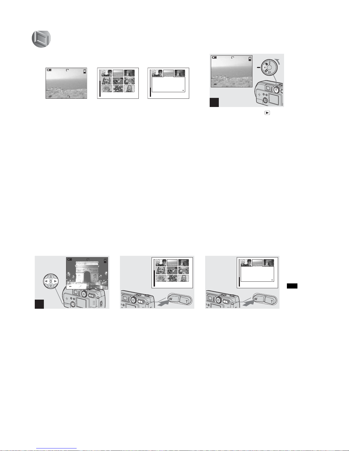
Viewing single images
, Turn the mode dial to , and
turn on the power.
The last image you shot will be displayed.
1
FILE BACK/NEXT
10:30
PM
2002 7 4100-0028
6/8
640
Viewi
ng s
till i
mages
37
Viewing still images
, Select Still Im age us ing b/B on
the control button.
b : Displays the previous image.
B : Displays the next image.
Viewing Index
(9 or 3 images display)
, Press the Zoom W button once.
The display switches to the Index (9
images) screen.
To display the previous (next) Index
screen
Press v/V/b/B on the control button to
move the yellow frame up/down/left/right.
, Press the Zoom W button once
more.
The display switches to the Index (3
images) screen.
When you press v/V on the control button,
the remaining image information is
displayed.
To display the previous (next) Index
screen
Press b/B on the control button.
To return to the Single image screen
Repeatedly press the Zoom T button, or
press the center z on the control button.
2
FILE BACK/NEXT
10:30
PM
2002 7 4100-0029
6/8
640
•
SINGLE
•
SINGLE
APERTURE VALUE :
SHUTTER SPEED :
EXPOSURE VALUE :
ISO
:
F2.2
1/125
0.0
100
10:30
PM
2002 7 4100-0028
1-17
DSC-P71/P71M
38
Viewing images on a TV screen
, Using the video connecting
cable, connect the VIDEO OUT
jack of the camera to the Image
of the TV set.
• Connect the video cable to the camera and the
TV set only after confirming that both are
turned off.
, Turn on the power of the TV
set, and set the TV/Video
toggle switch of the TV to
“Video.”
• Depending on your TV set, the name and
location of this switch may be different.
, Turn the Mode dial to and
turn on the camera.
Press b/B on the control button to select an
image.
• When using this feature, it may be necessary to
switch the video output signal to match that of
your TV system (see page 98).
1
VIDEO OUT jack
Video connecting cable
(supplied)
2
TV/Video toggle switch
FILE BACK/NEXT
10:30PM2002 7 4100-0028
6/8
640
3
39
Deleting still images
Watching the playback picture
on TV
If you want to view the playback
picture on a TV, you need a TV having
a video input jack and a video
connecting cable.
The color system of the TV must be the
same as that of your digital still camera.
Check the following list:
NTSC system
Bahama Islands, Bolivia, Canada,
Central America, Chile, Columbia,
Ecuador, Jamaica, Japan, Korea,
Mexico, Peru, Surinam, Taiwan, the
Philippines, the U.S.A., Venezuela, etc.
PAL system
Australia, Austria, Belgium, China,
Czech Republic, Denmark, Finland,
Germany, Holland, Hong Kong, Italy,
Kuwait, Malaysia, New Zealand,
Norway, Portugal, Singapore, Slovak
Republic, Spain, Sweden, Switzerland,
Thailand, United Kingdom, etc.
PAL-M system
Brazil
PAL-N system
Argentina, Paraguay, Uruguay
SECAM system
Bulgaria, France, Guiana, Hungary,
Iran, Iraq, Monaco, Poland, Russia,
Ukraine, etc.
Deleting images
, Turn the Mode dial to and
turn on the camera. Press b/B
on the control button to select
an image to be deleted.
1
FILE BACK/NEXT
10:30
PM
2002 7 4100-0028
5/5
2048
, Press the MENU button, press
b/B on the control button to
select “DELETE”, then press
the center z.
The image has not yet been deleted at this
point.
2
5/5
2048
SLIDEPRINT
PROTECT
OK
DELETE
MENU
button
Deleti
ng s
till i
mages
1-18
DSC-P71/P71M
40
Deleting images (continued)
, Select “OK” using v on the
control button, then press the
center z.
“MEMORY STICK ACCESS” is displayed
on the screen. When this message
disappears, the image has been deleted.
To cancel the deletion
Using V on the control button, choose
“CANCEL”, then press the center z.
3
5/5
2048
OK
DELETE
CANCEL
OK
Deleting on the Index (9 images) screen
, While an Index (9 images)
screen (page 37) is displayed,
press the MENU button, select
“DELETE” using b/B on the
control button, then press the
center z.
1
PROTECT PRINTDELETE
MENU
button
, Select “SELECT” using b/B on
the control button, then press
the center z.
To delete the entire screen
Select “ALL” using b/B on the control
button, then press the center z. Select
“OK” again, and press the center z. To halt
the deletion, select “EXIT”, then press the
center z.
2
CANCEL
DELETE
ALLSELECT
41
Deleting still images
, Select the image you want to
delete using v/V/b/B on the
control button then press the
center z.
The mark appears next to the selected
images. At this point, the images have not
yet been deleted. Put a mark next to all
of the images you want to delete.
• To cancel your selection, press the center z
one more time.
, Press the MENU button, select
“OK” using b/B on the control
button, then press the center
z.
When “MEMORY STICK ACCESS”
disappears, the images have been deleted.
To cancel the deletion
Using b on the control button, select
“EXIT”, then press the center z.
Deleting on the Index (3
images) screen
, While an Index (3 images)
screen (page 37) is displayed,
select the images you want to
delete using b/B on the control
button.
3
TO NEXT
MENU
•
SET
4
EXITDELETE OK
1
•
SINGLE
APERTURE VALUE :
SHUTTER SPEED :
EXPOSURE VALUE :
ISO
:
F2.2
1/125
0.0
100
10:30
PM
2002 7 4100-0028

1-19
DSC-P71/P71M
42
Deleting on the Index (3
images) screen (continued)
, Press the MENU button, and
select “DELETE” using the V
on the control button, then
press the center z.
At this point, the images have not yet been
deleted.
, Select “OK” using v on the
control button, then press the
center z.
When “MEMORY STICK ACCESS”
disappears, the image has been deleted.
To cancel the deletion
Use
V
on the control button to select
“CANCEL”, then press the center z.
2
•
OK
10:30
PM
2002 7 4100-0028
PROTECT
PRINT
DELETE
MENU
button
3
•
OK
10:30
PM
2002 7 4100-0028
OK
DELETE
CANCEL
43
Deleting still images
Formatting a “Memory Stick”
, Insert the “Memory Stick” you
want to format into the cam era.
Turn the mode dial to SET UP,
and turn on the power.
• The term “formatting” means preparing a
“Memory Stick” to record images; this process
is also called “initialization.” The “Memory
Stick” provided with this camera, and those
available commercially, are already formatted,
and can be used immediately. When you
format a “Memory Stick,” be aware that
all of the images in the “Memory Stick”
will be permanently deleted.
, Select
“”
(“SETUP 1”) using
v/V on the control button,
select “FORMAT” by pressing
B. Then, press B, s e le c t " OK"
using v/V, and press the
center z.
To cancel the formatting
Select “CANCEL” using V on the control
button, then press the center z.
, Select “OK” using v/V on the
control button, then press the
center z.
The “FORMATTING” message appears.
When this message disappears, the format
is complete.
1
2
SETUP 1
FORMAT :
FILE NUMBER :
/LANGUAGE :
CLOCK SET :
OK
CANCEL
OK
3
OK
READY?
FORMAT
ALL DATA WILL BE ERASED
CANCEL
O K

1-20
DSC-P71/P71M
44
Copying still images to your computer
Follow the steps below to copy the images
you shot to your computer.
Steps required by your OS
(Operating System)
• Step 1 may be unnecessary depending on your
OS.
• After you complete the installation of the USB
driver, step 1 is unnecessary.
Recommended com puter
environment
Recomm ended Windows environment
OS: Microsoft Windows 98, Windows
98SE, Windows 2000 Professional,
Windows Millennium Edition,
Windows XP Home Edition, or
Windows XP Professional
An OS installed at the factory (not
upgraded) is required for correct
operations. We cannot guarantee
operations for operating systems not
listed above.
CPU: MMX Pentium 200 MHz or faster
USB connector:
Provided as standard equipment
Recommended Macintosh environment
OS: Mac OS 8.5.1, 8.6, 9.0, 9.1, 9.2, or
Mac OS X(v10.0/v10.1)
An OS installed at the factory is
required for correct operations. For
the following models, update your
OS to Mac OS 9.0 or 9.1.
– iMac with Mac OS 8.6 installed at
the factory, and a slot loading type
CD-ROM drive
–iBook or Power Mac G4 with the
Mac OS 8.6 installed at the factory
USB connector:
Provided as standard equipment
• If you connect two or more USB devices to
your computer at one time, some devices,
including your camera, may not work,
depending on the type of USB device.
• Operations are not guaranteed when using a
USB hub.
• Operations are not guaranteed for all the
recommended environments mentioned above.
USB mode
There are two modes for a USB connection,
“NORMAL” and “PTP” modes. The
factory setting is the “NORMAL” mode.
This section describes the USB connection
using the “NORMAL” mode.
Communication with your
computer (for Windows users
only)
If you recover your computer from the
suspend or sleep mode, communication
between your camera and your computer
may not recover at the same time.
When a USB connector is not
provided on your computer
When neither a USB connector nor a
“Memory Stick” slot is provided, you can
copy images using an additional device. See
the Sony Website for details.
OS Steps
Windows 98/98SE/2000/MeSteps 1 to 5
(pages 45 to 53)
Windows XP Steps 2 to 5
(pages 46, 47, 49,
and 53)
Mac OS 8.5.1/8.6/
9.0/9.1/9.2,
Mac OS X (v10.0/v10.1)
Page 54
C
opying s
till i
mages to your computer
45
Copying still images to your computer
1 Installing the USB driver
, Turn on your computer, and
insert the s u p p lied CD-ROM
into the C D -ROM drive.
Do not connect your camera to your
computer at this time.
The opening window appears. If it does not
appear, double-click (My Computer) t
(ImageMixer) in order.
• This section describes how to establish a USB
connection using Windows Me as an example.
Required operations may be different
depending on your OS.
•Shut down all other applications before
installation of the driver.
• When you are using Windows 2000, log on as
Administrators.
, Click “USB Driver” on th e
opening window.
The “InstallShield wizard” appears.
, Click “ N ext.” When the
“Information” window
appears, click “Next,” and eject
the CD-ROM.
The USB driver installation starts. When
the installation is completed, the window
informs you of completion.
1
Opening window
2
Click here
3
Click here
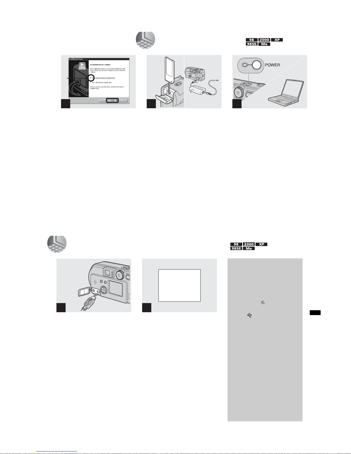
1-21
DSC-P71/P71M
46
, Click “Yes, I want to restart my
computer now,” then click
“Finish.”
Your computer restarts. Then, you can
establish the USB connection.
• You can use the “PIXELA ImageMixer for
Sony” software to copy images to your
computer. To install this software, click
“PIXELA ImageMixer,” on the operating
window, then follow instructions on each
window.
• Be sure to install DirectX when using the
“PIXELA ImageMixer for Sony” software.
Click “DirectX” and follow instructions on
each window. Your computer restarts when the
installation is completed.
4
1
2 Preparing your camera
, Insert the “M emory Stick” with
the images you want to copy
into the camera. Connect the
camera and the AC power
adaptor, and plug the adaptor
into a wa ll o u tlet (mains).
• For further details on the “Memory Stick,” see
page 23.
• For further details on the AC power adaptor,
see page 19.
1
“Memory
Stick”
To the
wall outlet
(mains)
3
AC power 2
adaptor
3
, Turn on the PC and your
camera.
2
47
Copying still images to your computer
3 Connecting your camera to your computer
, Open the jack cover, and
connect the supplied USB
cable to your camera. Then,
connect the other end of the
USB cable to your computer.
• When using a desktop computer, connect the
USB cable to the USB connector on the rear
panel.
• When using Windows XP, the copy wizard
automatically appears on the desktop. Proceed
to page 49.
“USB MODE NORMAL” appears on the
LCD screen of your camera. When a USB
connection is established for the first time,
your computer automatically runs the used
program to recognize your camera. Wait for
a while.
• If “USB MODE NORMAL” is not shown,
confirm that “USB CONNECT” is set to
“NORMAL” in the SET UP settings (page 98).
1
2
USB MODE
NORMAL
a a a a
Removing the USB cable
from your computer or the
“Memory Stick” from your
camera during a USB
connection
For Windows 2000, Me, or XP users
1 Double-click at the lower-right
corner of the desktop.
2 Click (Sony DSC), then click
“Stop.”
3 Confirm the device on the
confirmation window, then click
“OK.”
4 Click “OK.”
5 Disconnect the USB cable or
remove the “Memory Stick.”
For Windows 98 or 98SE users
Carry out only Step 5 above.
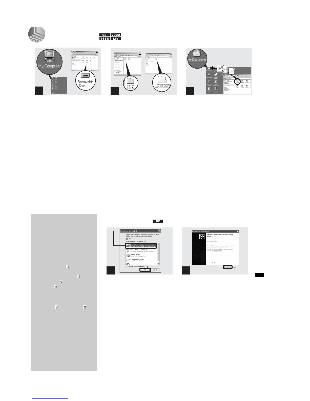
1-22
DSC-P71/P71M
48
4 Copying images
, Double-click “My Computer,”
then double-click “Removable
Disk.”
The contents of the “Memory Stick”
inserted in your camera appear.
• This section describes an example of copying
images into the “My Documents” folder.
• When using Windows XP, see pages 49 to 51.
• When the “Removable Disk” icon is not sho wn,
see the next page.
• You can use the “PIXELA ImageMixer for
Sony” software to copy images to your
computer. For details, see the software’s help
files.
, Double-click “D CIM,” then
double-click “100MSDCF.”
The “100MSDCF” folder opens.
• The “100MSDCF” folder contains the image
files you shot using your camera.
• The folder names vary depending on the type of
images they contain (page 51).
, Drag and drop the image files
into the “My Docum ents”
folder.
The image files are copied to the “My
Documents” folder.
• When you try to copy an image to a folder in
which an image with the same file name is
stored, the overwrite confirmation message
appears. When you want to overwrite the
existing image with the new one, click “Yes.”
When you do not want to overwrite it, click
“No,” then change the file name.
1
2 3
49
Copying still images to your computer
4 Copying images (for
Windows XP users)
, Click “Copy pictures to a folder
on my computer using
Microsoft Scanner and Camera
Wizard, ” then click “OK .”
The “Scanner and Camera Wizard”
appears.
• When following the steps on page 47, the copy
wizard appears on the desktop of your
computer.
, Click “ N e x t.”
The images stored in the “Memory Stick”
are displayed.
When a removable disk
icon is not shown
1 Right-click “My Computer,” then
click “Property.”
The “System Property” window
appears.
2 Confirm if other devices are already
installed.
1 Click “Device Manager.”
2 Double-click “ Other
Devices.”
3 Confirm if there is a “ Sony
DSC” or “ Sony Handycam”
with a mark.
3 If you find either of the devices
above, follow the steps below to
delete them.
1 Click “ Sony DSC” or “
Sony Handycam.”
2 Click “Delete.”
The “Device deletion
confirmation” window appears.
3 Click “OK.”
The device is deleted.
Try the USB driver installation again
using the supplied CD-ROM (page 45).
1
1
2
2
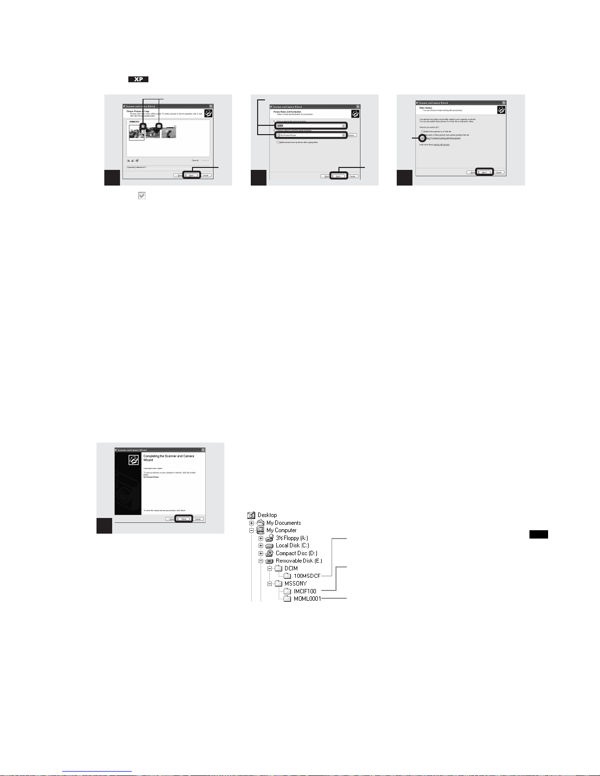
1-23
DSC-P71/P71M
50
4 Copying images (for Windows XP
users) (continued)
, Click to remov e the
checkmark from any images
you do not want to copy to
your computer, then click
“Next.”
The “Picture Name and Destination”
window appears.
, Specify the image file names to
be copied and the copy
destination.
Copying of the images starts. When the task
is completed, the “Other Options” window
appears.
• Copy images into the “My Documents” folder.
, Click “Nothing. I’m finished
working with these pictures,”
then click “Next.”
The “Completing the Scanner and Camera
Wizard” window appears.
3
1
2
4
1
2
5
1
2
51
Copying still images to your computer
, Click “ F inish.”
The wizard closes.
• When you want to continue copying other
images, disconnect the USB cable once and
reconnect it. Then, follow the process from
Step 1.
6
Click here
Image file storage destinations and file names
The image files recorded with your camera
are grouped as folders in the “Memory
Stick,” depending on the recording modes.
Example: when viewing folders on
Windows Me
Folder containing still image/Clip Motion/
Multi Burst mode image data
Folder containing E-mail mode image data
Folder containing Movie data
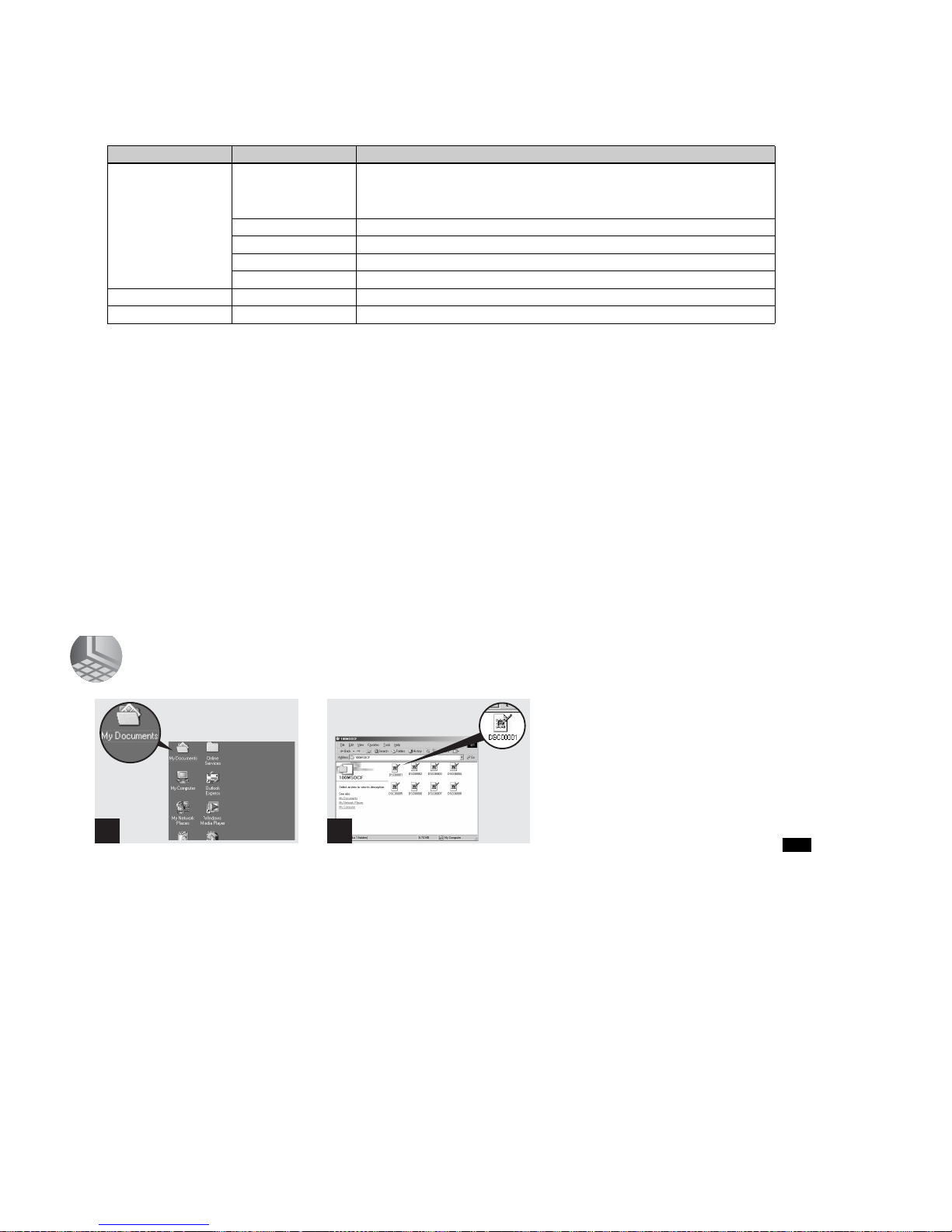
1-24
DSC-P71/P71M
52
Image file storage destinations and file names (continued)
Note on the table
• The meanings of the file names are as above:
ssss stands for any number within the range from 0001 to 9999.
• The numerical portions of the following files are the same.
–A small-size image file shot in E-MAIL mode and its corresponding image file
–An image file shot with Clip Motion and its corresponding index image file
Folder File name File meaning
100MSDCF DSC0ssss.JPG • Still image files sh o t n o rmally
•Still image files sh o t in
–E-MAIL mode (page 65)
–Multi Burst mode (page 64)
CLP0ssss.GIF
• Clip Motion files shot in NORMAL mode (page62)
CLP0ssss.THM
• Index image files of Clip Motion files
shot in NORMAL mode
MBL0ssss.GIF
• Clip Motion files
shot in MOBILE mode (page 62)
MBL0ssss.THM
• Index image files of Clip Motion files
shot in MOBILE mode
IMCIF100 DSC0ssss.JPG
• Small-size image files shot in E-MAIL mode (page65)
MOML0001 MOV0ssss.M P G
• Movie files
shot normally (page 74)
53
Copying still images to your computer
5 Viewing the images on your computer
, Double-click “My Documents”
on the desktop.
The “My Documents” folder opens.
• This section describes the steps followed for
copying images to the “My Documents” folder
on page 48.
• When using Windo ws XP, click “Start”t“My
Documents” in that order.
• You can use the “PIXELA ImageMixer for
Sony” software to view images on your
computer. For details, see the software’s help
files.
, Double-click the desired image
file.
The image file opens.
1 2
 Loading...