

Sony CXLZX-7 Service manual

CX-LZX7
Main Unit
Amplifier section
For the U.S. model
AUDIO POWER SPECIFICATIONS
POWER OUTPUT AND TOTAL HARMONIC
DISTORTION:
With 6-ohm loads, both channels driven, from
120 – 10,000 Hz: rated 60 watts per channel
minimum RMS power, with no more than 10%
total harmonic distortion from 250 milliwatts to
rated output.
North American model:
Continuous RMS power output (reference):
60 + 60 W
(6 ohms at 1 kHz, 10%
THD)
Total harmonic distortion less than 0.05% (6 ohms at
1kHz, 30 W)
European model:
DIN power output (rated): 45 + 45 W
(6 ohms at 1 kHz, DIN)
Continuous RMS power output (reference):
60 + 60 W
(6 ohms at 1 kHz, 10%
THD)
Music power output (reference):
100 + 100 W
(6 ohms at 1 kHz, 10%
THD)
Other models:
The following measured at 220 – 240 V AC, 50/60 Hz
DIN power output (rated): 45 + 45 W
(6 ohms at 1 kHz, DIN)
Continuous RMS power output (reference):
60 + 60 W
(6 ohms at 1 kHz, 10%
THD)
Inputs
AUX IN (RCA pin jacks): Sensitivity 1 V,
impedance 47 kilohms
Outputs
PHONES (stereo mini jack):
accepts headphones with
an impedance of 32 ohms
or more
SPEAKER: accepts impedance of
6 ohms
SUB WOOFER OUT: voltage 1.5 V
CD player section
System Compact disc and dig i tal
audio system
Laser Semiconductor laser
(λ=770 – 810 nm)
Emission duration:
continuous
Frequency response 20 Hz – 20 kHz
Signal-to-noise ratio More than 90 dB
Dynamic range More than 90 dB
Tape deck section
Recording system 4-track 2-channel stereo
Frequency response 100 – 10,000 Hz, using
Sony TYPE I cassettes
Tuner section
FM stereo, FM/AM superheterodyne tuner
FM tuner section
Tuning range
North American model: 87.5 – 108.0 MHz
(100-kHz step)
Other models: 87.5 – 108.0 MHz
(50-kHz step)
Antenna FM lead antenna
Antenna terminals 75 ohms unbalanced
Intermediate frequency 10.7 MHz
SERVICE MANUAL
Ver 1.0 2004.05
• CX-LZX7 is the Amplifier, CD pla yer, Tape
Deck and Tuner section in AWP-ZX7.
Model Name Using Similar Mechanism NEW
CD
Section
TAPE
Section
CD Mechanism Type CDM69CV-F4BD81B2
Base Unit Name BU-F4BD81B2
Optical Pick-up Name KSM-215CFP/C2NP
Model Name Using Similar Mechanism NEW
Tape Transport Mechanism Type CMAL1Z250A
US Model
Canadian Model
AEP Model
UK Model
E Model
9-877-859-01
2004E1679-1
2004.05
SPECIFICATIONS
Sony Corporation
Home Audio Company
Published by Sony Engineering Corporation
— Continued on next page —
MICRO HI-FI COMPONENT SYSTEM
CX-LZX7
P
N
E
K
O
z
P
N
E
O
D
s
A
M
A
D
w
T
P
E
O
A
l
I
AM tuner section
uning range
an-American model: 530 — 1,710 kHz
(with the tuning interval
set at 10 kHz)
531 — 1,710 kHz
(with the tuning interval
set at 9 kHz)
uropean model: 531 — 1,602 kHz
(with the tuning interval
set at 9 kHz)
ther models: 530 — 1,710 kHz
(with the tuning interval
set at 10 kHz)
531 — 1,602 kHz
(with the tuning interval
set at 9 kHz)
ntenna AM loop antenna, externa
antenna terminal
ntermediate frequency 450 kHz
General
ower requirements
orth American model: 120 V AC, 60 Hz
uropean model: 230 V AC, 50/60 Hz
orean model: 220 V AC, 60 Hz
ther models: 120 V, 220 V or
230 — 240 V AC, 50/60 H
Adjustable with voltage
selector
ower consumption
orth American model: 60 W
uropean model: 60 W
0.3 W (in Power Saving
mode)
ther models: 70 W
imensions (w/h/d) incl. projecting parts and control
mplifier/Tuner/Tape/CD section:
Approx. 190 ´ 277
361.4 mm
ass
mplifier/Tuner/Tape/CD section:
Approx. 6.2 kg
esign and specifications are subject to change
ithout notice.
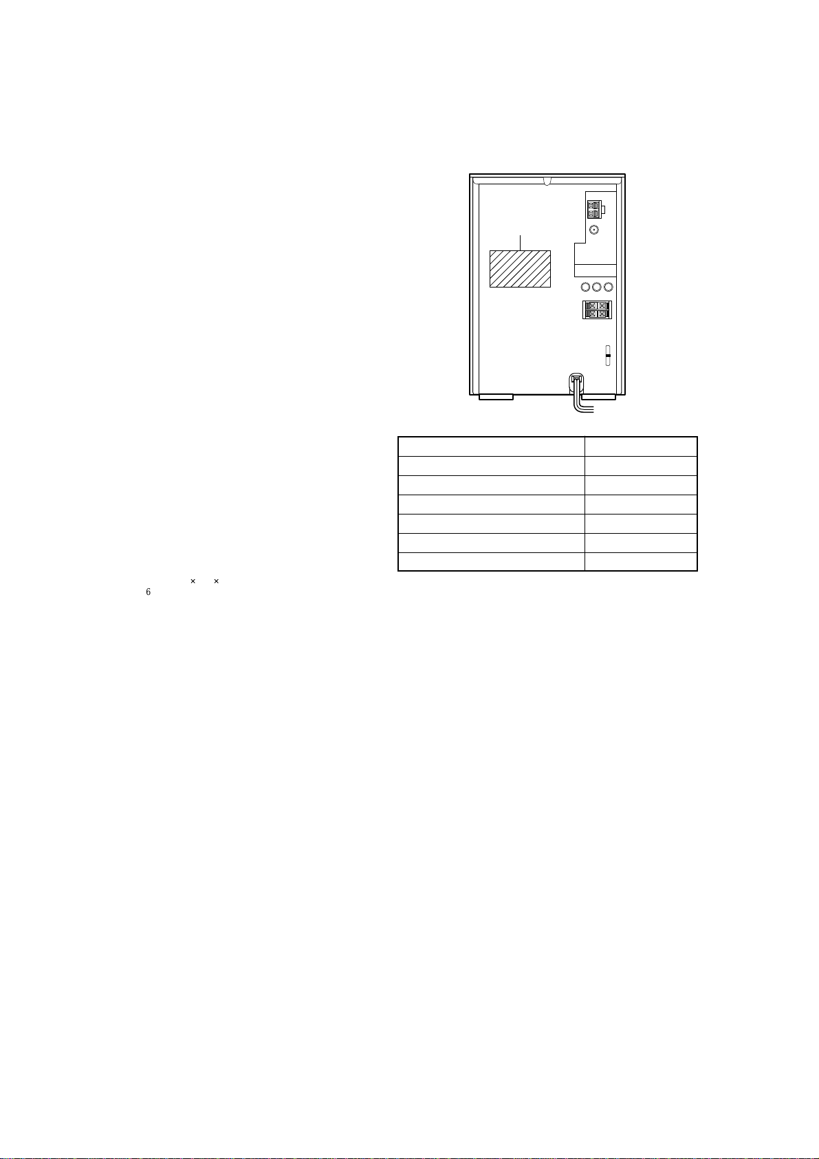
MODEL IDENTIFICATION
— Back Panel —
Part No.
Model Name Part No.
US model 4-254-181-0<
AEP, UK models 4-254-181-1<
E51 model 4-254-181-3<
CND model 4-254-181-4<
SP model 4-254-181-6<
Korean model 4-254-181-7<
´
•Abbreviation
CND : Canadian model
E51 : Chilean and Peruvian models
KR : Korean model
SP : Singapore model
COMPONENTS IDENTIFIED BY MARK 0 OR DOTTED LINE
WITH MARK 0 ON THE SCHEMATIC DIAGRAMS AND IN
THE PARTS LIST ARE CRITICAL TO SAFE OPERATION.
REPLACE THESE COMPONENTS WITH SONY PARTS WHOSE
SAFETY-RELATED COMPONENT WARNING!!
PART NUMBERS APPEAR AS SHO WN IN THIS MANUAL OR
IN SUPPLEMENTS PUBLISHED BY SONY.
ATTENTION AU COMPOSANT AYANT RAPPORT
À LA SÉCURITÉ!
LES COMPOSANTS IDENTIFÉS P AR UNE MARQUE 0 SUR LES
DIAGRAMMES SCHÉMA TIQUES ET LA LISTE DES PIÈCES SONT
CRITIQUES POUR LA SÉCURITÉ DE FONCTIONNEMENT. NE
REMPLACER CES COMPOSANTS QUE PAR DES PIÈSES SONY
DONT LES NUMÉROS SONT DONNÉS DANS CE MANUEL OU
DANS LES SUPPÉMENTS PUBLIÉS PAR SONY.
2

TABLE OF CONTENTS
CX-LZX7
1. SERVICING NOTES ................................................ 4
2. GENERAL ................................................................... 5
3. DISASSEMBLY
3-1. Side Panel (L)(R), Top Panel, Back Panel....................... 8
3-2. CD Mechanism Section................................................... 8
3-3. Front Panel Section ......................................................... 9
3-4. FRONT Board ................................................................. 9
3-5. Cassette Deck Mechanism, USB Board .......................... 10
3-6. Cassette Panel.................................................................. 10
3-7. Power T ransformer .......................................................... 11
3-8. MAIN Board Section....................................................... 11
3-9. CD Mechanism Deck (CDM69CV-F4BD81B2) ............. 12
3-10. Optical Pick-up Section................................................... 12
3-11. Base Unit (BU-F4BD81B2) ............................................ 13
3-12. BD Board, Optical Pick-up (KSM-215CFP/C2NP)........ 13
3-13. SW Board, Bracket (TOP) Assy...................................... 14
3-14. CONNECTOR Board...................................................... 14
3-15. Motor (Stocker) Assy (Stocker)(M761) .......................... 15
3-16. Motor (Roller) Assy (Roller)(M781)............................... 15
3-17. Motor (Mode) Assy (Mode)(M771) ................................ 16
3-18. Rubber Roller (Slider) Assy ............................................ 16
3-19. Timing Belt (Front/Rear)................................................. 17
3-20. Cam (Gear) ...................................................................... 17
3-21. SENSOR Board............................................................... 18
4. ASSEMBLY
4-1. How to Install the Cam (EJECT LOCK)......................... 19
4-2. How to Install the Cam (GEAR) ..................................... 19
4-3. How to Install the Gear (MODE C) ................................ 20
4-4. How to Install the Gear (MODE CAM) .......................... 20
4-5. How to Install the Rotary Encoder (S702),
Gear (STOCKER COMMUNICATION) ........................ 21
4-6. How to Install the Stocker Assy ...................................... 21
5. TEST MODE ............................................................... 22
6. MECHANICAL ADJUSTMENTS......................... 23
8. DIAGRAMS
8-1. Block Diagram — BD/Changer Section — .................... 28
— MAIN Section — ....................................................... 29
8-2. Printed Wiring Boards — BD Section — ....................... 30
8-3. Schematic Diagram — BD Section —............................ 31
8-4. Printed Wiring Boards — Changer Section — ............... 32
8-5. Schematic Diagram — Changer Section —.................... 33
8-6. Printed Wiring Boards — FRONT Section — ................ 34
8-7. Schematic Diagram — FRONT Section — .................... 35
8-8. Printed Wiring Boards — MAIN Section — .................. 36
8-9. Schematic Diagram — MAIN Section 1 —.................... 37
8-10. Schematic Diagram — MAIN Section 2 —.................... 38
8-11. Schematic Diagram — MAIN Section 3 —.................... 39
8-12. Schematic Diagram — MAIN Section 4 —.................... 40
8-13. Schematic Diagram — MAIN Section 5 —.................... 41
8-14. Schematic Diagram
—MAIN Section 6/P ower Section — ............................ 42
8-15. Printed Wiring Boards — Power Section —................... 43
8-16. Printed Wiring Boards — USB Section — ..................... 44
8-17. Schematic Diagram — USB Section —......................... 44
9. EXPLODED VIEWS
9-1. Panel Section ................................................................... 52
9-2. Front Section ................................................................... 53
9-3. Chassis Section................................................................ 54
9-4. CD Mechanism Deck Section 1
(CDM69CV-F4BD81B2) ................................................ 55
9-5. CD Mechanism Deck Section 2
(CDM69CV-F4BD81B2) ................................................ 56
9-6. CD Mechanism Deck Section 3
(CDM69CV-F4BD81B2) ................................................ 57
9-7. CD Mechanism Deck Section 4
(CDM69CV-F4BD81B2) ................................................ 58
9-8. CD Mechanism Deck Section 5
(CDM69CV-F4BD81B2) ................................................ 59
9-9. CD Mechanism Deck Section 6
(CDM69CV-F4BD81B2) ................................................ 60
9-10. CD Mechanism Deck Section 7
(CDM69CV-F4BD81B2) ................................................ 61
9-11. Optical Pick-up Section................................................... 62
7. ELECTRICAL ADJUSTMENTS .......................... 23
10. ELECTRICAL PARTS LIST .................................. 63
3
CX-LZX7
0
er
)
SECTION 1
SERVICING NOTES
Notes on chip component replacement
•Never reuse a disconnected chip component.
• Notice that the minus side of a tantalum capacitor may be
damaged by heat.
Flexible Circuit Board Repairing
•Keep the temperature of soldering iron around 270˚C
during repairing.
• Do not touch the soldering iron on the same conductor of the
circuit board (within 3 times).
• Be careful not to apply force on the conductor when soldering
or unsoldering.
SAFETY CHECK-OUT
After correcting the original service problem, perform the following
safety checks before releasing the set to the customer:
Check the antenna terminals, metal trim, “metallized” knobs, screws,
and all other exposed metal parts for AC leakage. Check leakage as
described below.
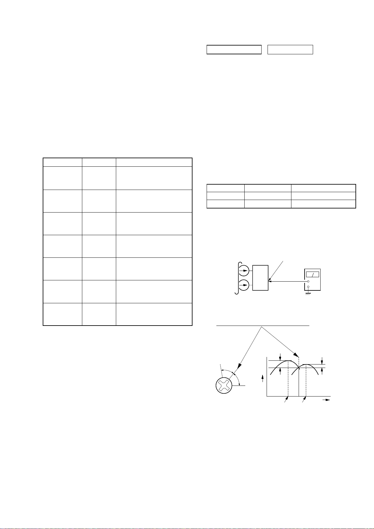
LEAKAGE
The AC leakage from any exposed metal part to earth ground and
from all exposed metal parts to any exposed metal part having a
return to chassis, must not exceed 0.5 mA (500 microamperes).
Leakage current can be measured by any one of three methods.
1. A commercial leakage tester, such as the Simpson 229 or RCA
WT -540A. Follow the manuf acturers’ instructions to use these
instruments.
2. A battery-operated AC milliammeter. The Data Precision 245
digital multimeter is suitable for this job.
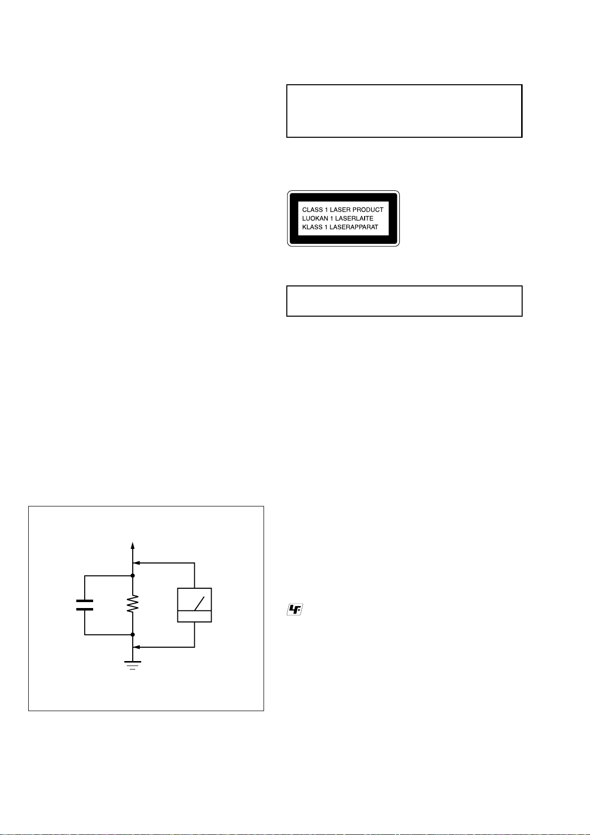
3. Measuring the voltage drop across a resistor by means of a
VOM or battery-operated A C voltmeter . The “limit” indication
is 0.75 V, so analog meters must have an accurate low-v oltage
scale. The Simpson 250 and Sanwa SH-63Trd are examples
of a passive VOM that is suitable. Nearly all battery operated
digital multimeters that have a 2V A C range are suitable. (See
Fig. A)
To Exposed Metal
Parts on Set
1.5 k
.15 µF
Fig.A. Using an AC voltmeter to check AC leakage.
Ω
Earth Ground
AC
voltmet
(0.75 V
CAUTION
Use of controls or adjustments or performance of procedures
other than those specified herein may result in hazardous radiation
exposure.
This appliance is classified as a CLASS 1 LASER product. The
CLASS 1 LASER PRODUCT MARKING is located on the rear
exterior.
Laser component in this product is capable of emitting radiation
exceeding the limit for Class 1.
NOTES ON HANDLING THE OPTICAL PICK-UP
BLOCK OR BASE UNIT
The laser diode in the optical pick-up block may suffer electrostatic
break-down because of the potential difference generated by the
charged electrostatic load, etc. on clothing and the human body.
During repair, pay attention to electrostatic break-down and also
use the procedure in the printed matter which is included in the
repair parts.
The flexible board is easily damaged and should be handled with
care.
NOTES ON LASER DIODE EMISSION CHECK
The laser beam on this model is concentrated so as to be focused on
the disc reflective surface by the objective lens in the optical pickup block. Therefore, when checking the laser diode emission,
observe from more than 30 cm away from the objective lens.
LASER DIODE AND FOCUS SEARCH OPERATION
CHECK
Carry out the “S curve check” in “CD section adjustment” and check
that the S curve waveforms is output three times.
UNLEADED SOLDER
Boards requiring use of unleaded solder are printed with the leadfree mark (LF) indicating the solder contains no lead.
(Caution: Some printed circuit boards may not come printed with
the lead free mark due to their particular size)
: LEAD FREE MARK
Unleaded solder has the following characteristics.
• Unleaded solder melts at a temperature about 40 °C higher
than ordinary solder.
Ordinary soldering irons can be used but the iron tip has to be
applied to the solder joint for a slightly longer time.
Soldering irons using a temperature regulator should be set to
about 350 °C.
Caution: The printed pattern (copper foil) may peel away if
the heated tip is applied for too long, so be careful!
• Strong viscosity
Unleaded solder is more viscou-s (sticky, less prone to flow)
than ordinary solder so use caution not to let solder bridges
occur such as on IC pins, etc.
• Usable with ordinary solder
It is best to use only unleaded solder but unleaded solder may
also be added to ordinary solder.
4

SECTION 2
B
C
D
D
D
D
D
F
i
,
)
)
GENERAL
List of button locations and reference pages
CX-LZX7
This section is extracted
from instruction manual.
How to use this page
Use this page to find the location of buttons and other
parts of the system that are mentioned in the text.
Main unit
ALPHABETICAL ORDER
A – O
ASS control w; (20)
D SYNC 7 (18)
IRECTION ql (17, 18, 19, 22)
ISC 1 – 5 qa (10, 11, 13, 18)
isc slot qs (10)
ISPLAY wd (16, 23)
isplay window 6
UNCTION 5 (9, 10, 13, 14, 15,
17, 19, 26, 29, 31)
-Bass qf (20, 34)
P – Z
PHONES jack ws
PLAY MODE ql (11, 13, 18)
Remote sensor 8
TREBLE control wa (20)
TUNER BAND 4 (14, 15, 19)
TUNING +/– qj (14, 15)
TUNING MODE ql (14, 15)
USB port qh (25, 30)
VOLUME control qg (29)
1
23456 89
Illustration number
r
DISPLAY wd (16, 23)
RR
Name of button/part Reference page
BUTTON DESCRIPTIONS
?/1 (power) 1 (8, 15, 26, 34)
TAPE nN (play) 2 (17, 18
22)
CD NX (play pause) 3 (11)
z REC PAUSE/START 9 (18
Z CD (eject) 0 (9, 10)
Z PUSH qd (17)
./> (go back/go forward
qj (11)
m/M (rewind/fast forward)
qj (9, 11, 15, 17)
x (stop) qk (11, 15, 17, 18)
7
0
wd
ws
wa
w;
ql
qk
qj
qa
qs
qd
qf
qg
qh
5
CX-LZX7
A
A
C
C
C
C
D
D
E
E
)
U
1
2
3
e
4
5
e
6
•
t
•
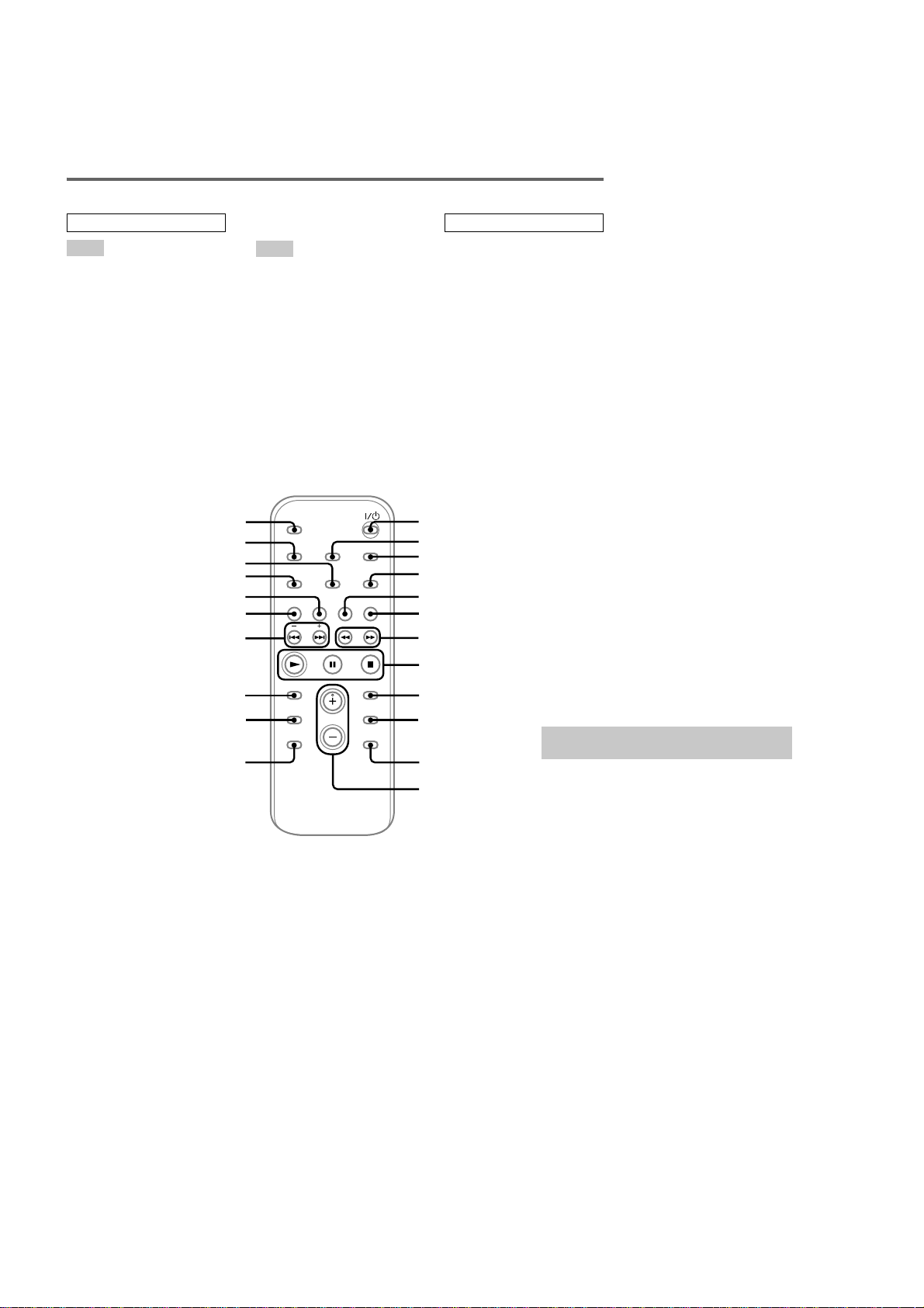
Remote control
ALPHABETICAL ORDER
A – E
LBUM + qa (11, 13, 18)
LBUM – qd (11, 13, 18)
D qk (10, 13, 19)
LEAR qg (13)
LOCK/TIMER SELECT 2
(21, 22)
LOCK/TIMER SET 3 (9, 21,
22)
ISC SKIP 0 (11, 13)
ISPLAY wa (16, 23)
NTER 9 (9, 13, 14, 21, 22)
Q qf (20)
F – Z
FM MODE 4 (16)
FUNCTION 6 (10, 13, 14, 15,
17, 19, 26, 29, 31)
PLAY MODE w; (11, 13)
REPEAT 4 (12)
SLEEP ws (20)
TAPE qj (17, 19)
TUNER BAND 5 (14, 15, 19)
TUNER MEMORY ql (14)
TUNING MODE w; (14, 15)
VOLUME +/– qs (21, 29)
ws
wa
w;
ql
qk
qj
qh
BUTTON DESCRIPTIONS
?/1 (power) 1 (8, 15, 21, 26)
m/M (rewind/fast forward)
7 (11, 15, 17)
X (pause) 8 (11, 17)
x (stop) 8 (11, 17, 18, 22)
N (play) 8 (11, 17)
–/+ (tuning) qh (14, 20)
./> (go back/go forward
qh (9, 11, 21)
1
2
3
4
5
6
7
8
qg
qf
qd
9
q;
qa
qs
Setting the clock
se buttons on the remote for the operation.
Press ?/1 to turn on the system.
Press CLOCK/TIMER SET.
Press . or > repeatedly to set th
hour.
Press ENTER.
Press . or > repeatedly to set th
minute.
Press ENTER.
The clock starts working.
To adjust the clock
1 Press CLOCK/TIMER SET.
2 Press . or > until “CLOCK SET?”
appears, then press ENTER.
3 Do the same procedures as step 3 to 6
above.
Notes
The clock settings are canceled when you disconnec
the power cord or if a power failure occurs.
You cannot set the clock in Power Saving Mode
(page 23).
6
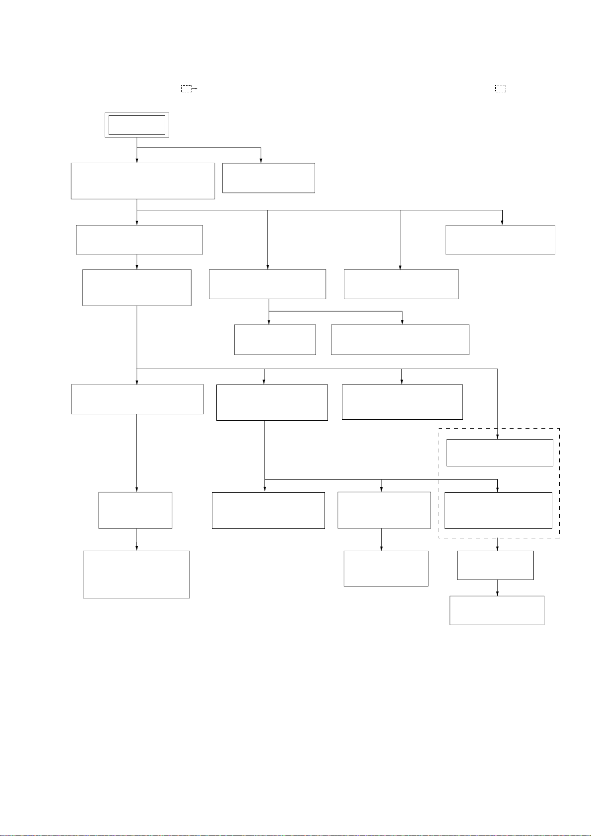
•This set can be disassembled in the order shown below.
•The dotted square with arrow (
SET
) prompts you to move to the next job when all of the works within the dotted square ( ) are completed.
CX-LZX7
SECTION 3
DISASSEMBLY
3-1.SIDE PANEL (L) (R), TOP PANEL,
3-2.CD MECHANISM SECTION
3-9.CD MECHANISM DECK
(CDM69CV-F4BD81B2)
3-10.OPTICAL PICK-UP SECTION
BACK PANEL
(Page 8)
(Page 8)
(Page 12)
(Page 12)
BRACKET (TOP) ASSY
3-6.CASSETTE PANEL
(Page 10)
3-3.FRONT PANEL SECTION
(Page 9)
3-4.FRONT BOARD
(Page 9)
3-13.SW BOARD,
(Page 14)
3-8.MAIN BOARD SECTION
(Page 11)
3-7.POWER TRANSFORMER
(Page 11)
3-5.CASSETTE DECK MECHANISM,
USB BOARD
(Page 10)
3-15.MOTOR (STOCKER)
ASSY (STOCKER) (M761)
(Page 15)
3-14.CONNECTOR BOARD
(Page 14)
3-11.BASE UNIT
(BU-F4BD81B)
(Page 13)
3-12.BD BOARD,
OPTICAL PICK-UP
(KSM-215CFP/C2NP)
(Page 13)
3-16.MOTOR (ROLLER)
ASSY (ROLLER) (M781)
(Page 15)
3-18.RUBBER ROLLER
(SLIDER) ASSY
(Page 16)
3-19.TIMING BELT
(FRONT/REAR)
(Page 17)
3-17.MOTOR (MODE)
ASSY (MODE) (M771)
(Page 16)
3-20.CAM (GEAR)
(Page 17)
3-21.SENSOR BOARD
(Page 18)
7

CX-LZX7
n
))
Note: Follow the disassembly procedure in the numerical order given.
3-1. SIDE PANEL (L)(R), TOP PANEL, BACK PANEL
qa top panel
3 side panel (L)
2 three claws
9 screw
(QT2+3 × 10)
1 four screws
(+BVTP3 × 10(BLK))
qj connector
2p(CN292)
0 screw
(QT2+3 × 10)
qh w
ire (flat type)
15core(CN602)
qs screw
(QT2+3 × 10)
qf screw
(QT2+3 × 10)
7 screw (+BVTP3 × 10(BLK))
qg nine screws
(+BVTP3 × 10(BLK
qk back panel
qd three screws
(QT2+3 × 10)
5 three claws
3-2. CD MECHANISM SECTION
3 screw
(QT2+3 × 10)
5 claw
8 screw
(QT2+3 × 10)
6 side panel (R)
2 w
ire (flat type)
27core (CN901)
4 six screws
(+BVTP3 × 10(BLK))
1 w
ire (flat type)
27core (CN902)
4 screw
(QT2+3 × 10)
6 CD mechanism sectio
8

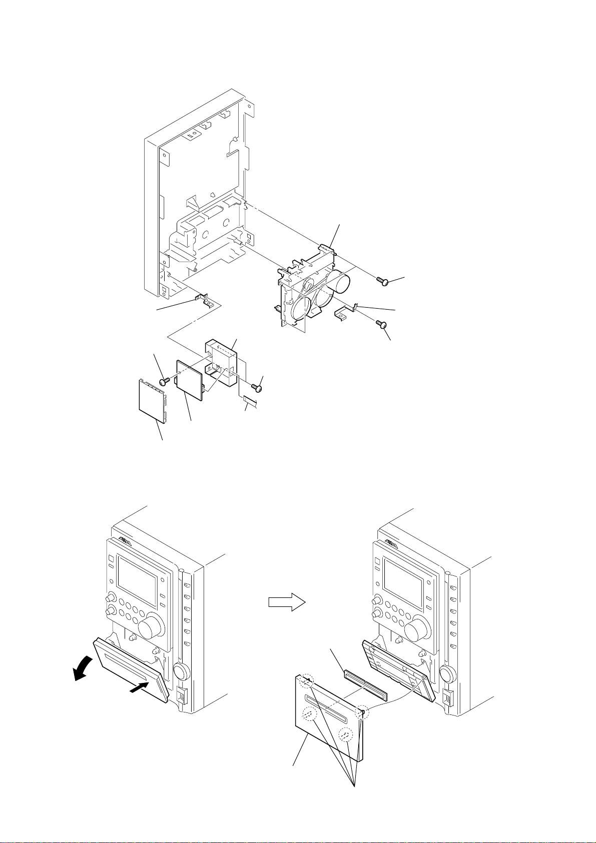
3-3. FRONT PANEL SECTION
3 connector
(CN203)
9 connector
(CN302)
1 w
ire (flat type)
19core (CN904)
4 w
ire (flat type)
7core (CN701)
0 front panel section
2 w
ire (flat type)
8core (
cassette deck mechanism
)
5 two screws
(+BVTP3 × 6)
6 screw
(QT2+3 × 6)
7 screw
(QT2+3 × 6)
8 two claws
8)
CX-LZX7
3-4. FRONT BOARD
2 knob (VOL)
1 two knobs (BT)
9 indicator (BASS),
I-BASS sheet
8 two claws
7 two claws
qa FRONT board
0 w
ire (flat type)
19core (CN905)
5 thirteen screws
(+BVTP3 × 10)
4 HP board
3 screw
(+BVWHTP3 ×
6 screw
(+BVTP3 × 10)
9
CX-LZX7
0)
3-5. CASSETTE DECK MECHANISM, USB BOARD
4 cassette deck mechanism
1 three screws
(+BVTP3 × 1
qa USB shield plate
8 screw
(+BVTP3 × 6)
3-6. CASSETTE PANEL
9 USB board
7 shield case
(USB B)
0 shield case
(USB A)
5 two screws
6 w
ire (flat type)
7core (CN801)
3 shield (DECK)
2 screw
(+BVTP3 × 10)
(+BVTP3 × 10)
10
5 window case
2
1
4 cassette panel
3 four claws
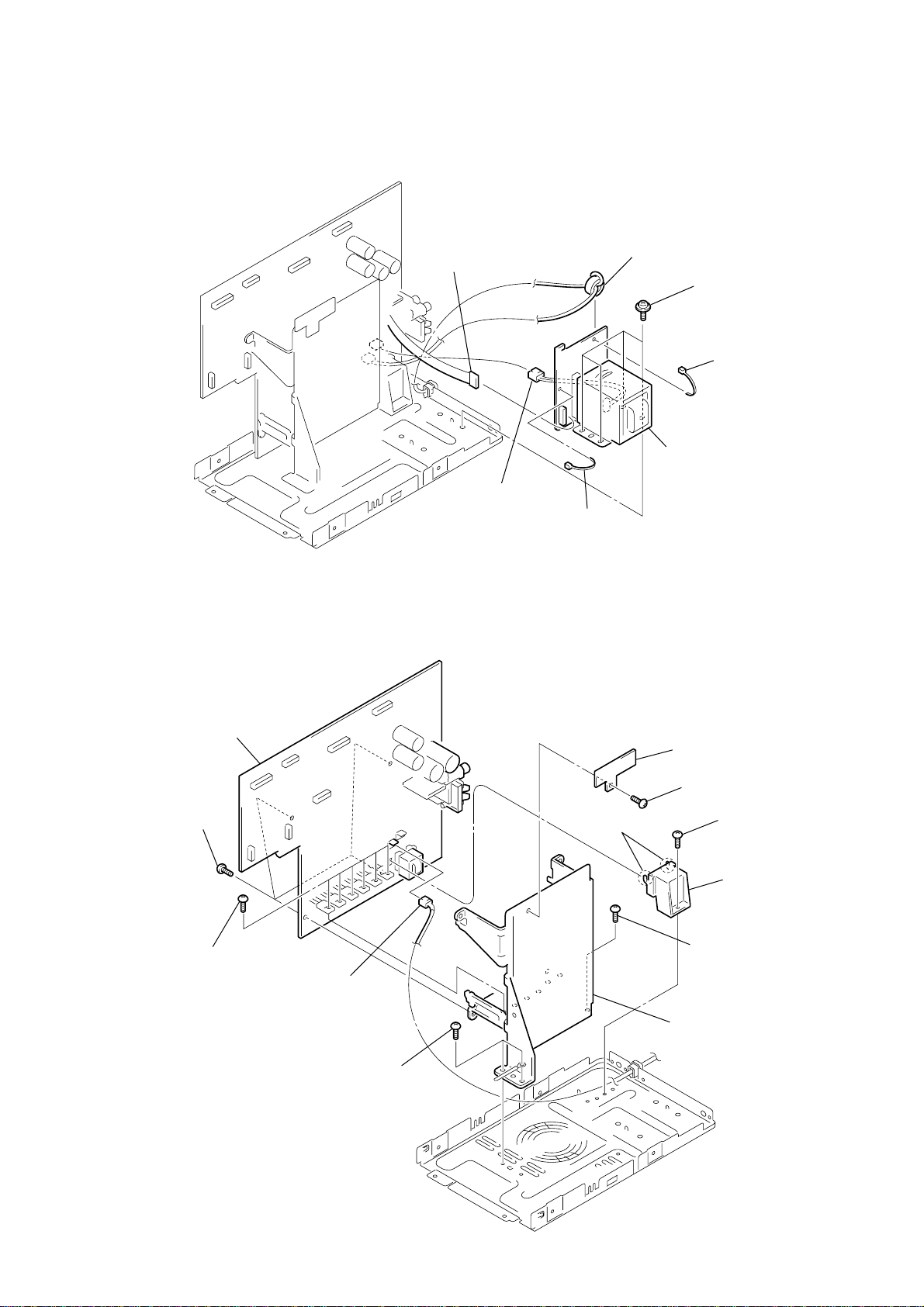
3-7. POWER TRANSFORMER
r
s
R)
)
CX-LZX7
3-8. MAIN BOARD SECTION
2 connector
5p(CN257)
6 connector
2p(CN251)
4 ferrite core
5 four s-screw
(ITC +4- 10
3 cable tie
7 power transforme
1 cable tie
qs MAIN board
8 four screws
(+BVTP3 × 10)
7 six screws
(+BVTP3 × 10)
1 connector
2p(CN202)
6 two screws
(BVIT3B+3- 8R W/O)
3 two claws
0 holder pwb
9 screw
(+BVTP3 × 10)
2 screw
(BVIT3B+3- 8R W/O
4 holder (pwb.PT)
5 screw
(BVIT3B+3- 8R W/O)
qa heat sink assy (MAIN)
11
CX-LZX7
2)
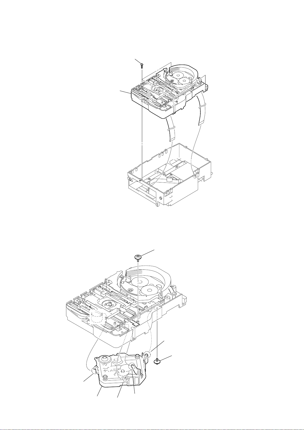
3-9. CD MECHANISM DECK (CDM69CV-F4BD81B2)
1 four screws
(+BVTP3 × 10)
2 CD mechanism deck
(CDM69CV-F4BD81B2)
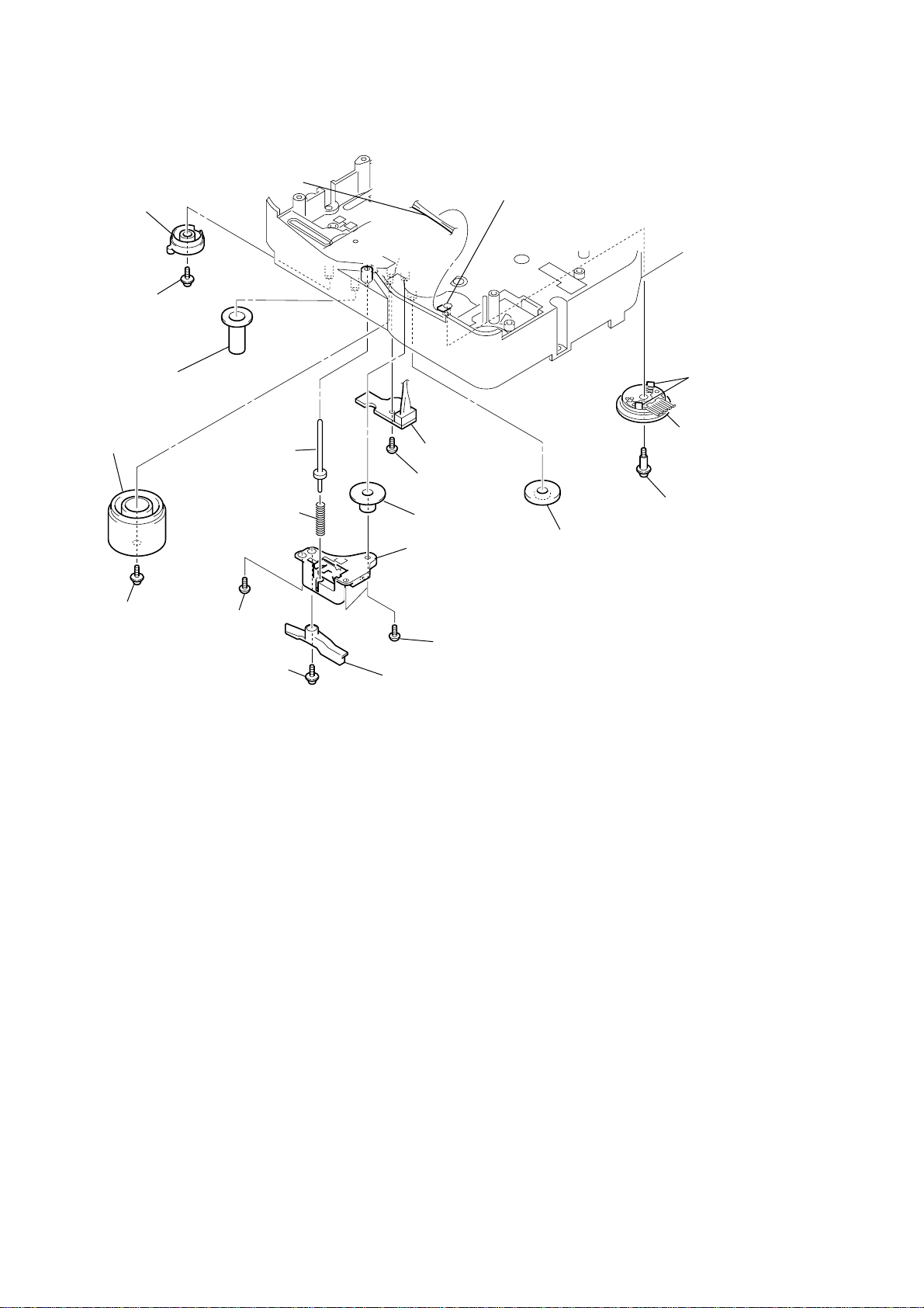
3-10. OPTICAL PICK-UP SECTION
2
screw
(+PTPWH) (M2) (DIA. 7)
3
boss
1 floating
screw
(DIA. 1
12
4
boss
7 optical pick-up section
5
boss
6
boss
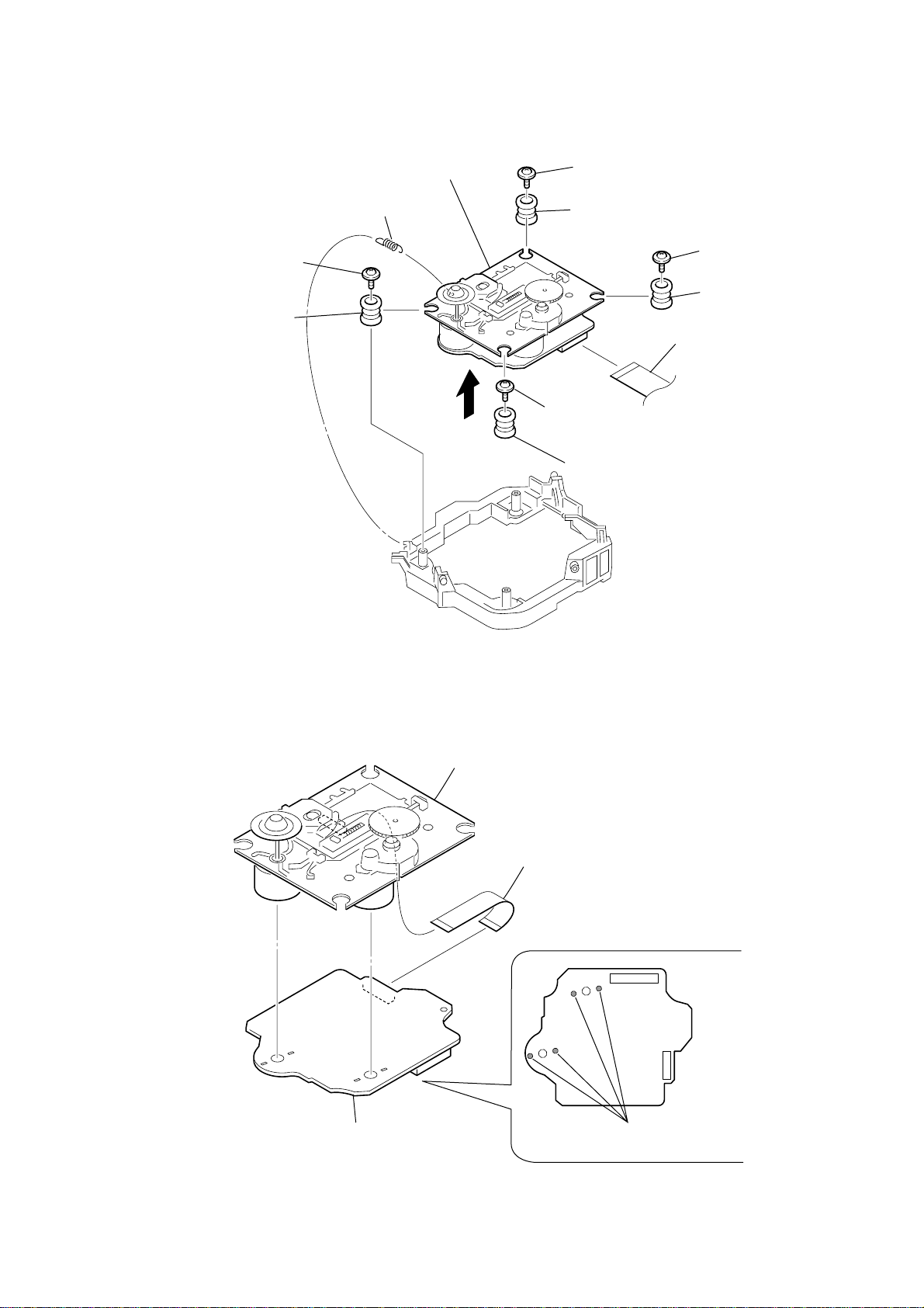
3-11. BASE UNIT (BU-F4BD81B2)
1 tension spring (BU30-1)
qs base unit (BU-F4BD81B2)
8 vibration proof rubber
3 floating screw
(+PTPWHM2.6 × 6)
5 floating screw
(+PTPWHM2.6 × 6)
4 floating screw
(+PTPWHM2.6 × 6)
2 floating screw
(+PTPWHM2.6 × 6)
9 vibration proof rubber
q; vibration proof rubbers
7 vibration proof rubber
qa w
ire (flat type)
19corre (CN202)
6
er
CX-LZX7
3-12. BD BOARD, OPTICAL PICK-UP (KSM-215CFP/C2NP)
3 BD board
4 optical pick-up (KSM-215CFP/C2NP)
2 wire (flat type) (16 core)
1 Remove the sold
(four portions).
13
CX-LZX7
8)
C
8)
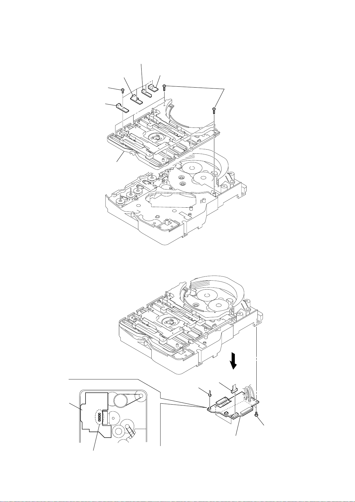
3-13. SW BOARD, BRACKET (TOP) ASSY
3
SW (2) board
1 four
screws
(BTP2.6
×
6)
2
SW (1) board
7
bracket (top) assy
4
SW (3) board
5
SW (4) board
6
six screws
(BVTP2.6
×
3-14. CONNECTOR BOARD
ONNECTOR board
– bottom view –
1
Remove five solders.
5 connector
(CN703)
4 connector
(CN710)
3
2
four screws
(BVTP2.6
6 CONNECTOR board
×
14
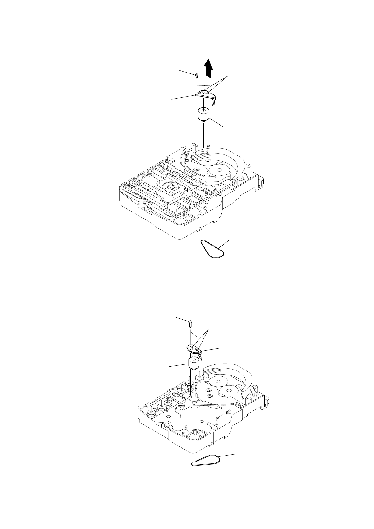
3-15. MOTOR (STOCKER) ASSY (STOCKER)(M761)
rs
y
rd
CX-LZX7
3
two screws
(BVTP2.6
5
stocker motor board
×
4
8)
2
Remove two solde
6 motor (stocker) ass
(stocker) (M761)
1 belt (stocker)
3-16. MOTOR (ROLLER) ASSY (ROLLER)(M781)
3
two screws
2
Remove two solders.
5
motor (roller) assy
(roller)(M781)
4 ROLLER MOTOR
1
belt (roller V)
boa
15
CX-LZX7
M
b
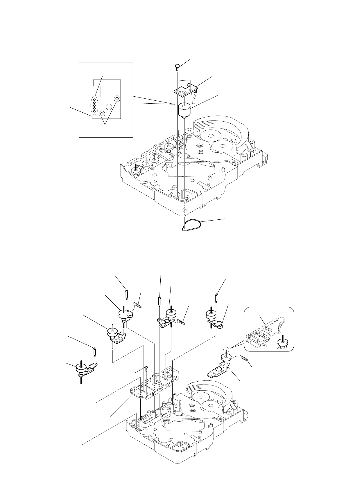
3-17. MOTOR (MODE) ASSY (MODE)(M771)
1
Remove five solders
of rotary encoder.
ODE MOTOR
oard
2
Remove two solders
of motor (M771)
3
two screws
(BVTP2.6
×
8)
4
MODE MOTOR board
6
motor (mode) assy
(mode) (M771)
3-18. RUBBER ROLLER (SLIDER) ASSY
0
rubber roller
(slider 4) assy
qa
rubber roller
(slider 2) assy
qs
step screw
qd
rubber roller
(slider 1) assy
8
qf
screw
(BVTP2.6
step screw
×
9 tension
spring
(slider 2)
8)
5
step screw
7
rubber roller
(slider 1) assy
6 tension spring
(base slider 4)
5
belt (mode V)
1
step screw
2
rubber roller
(slider S) assy
4
bracket (top) assy
3 tension spring
(base slider 5)
rubber roller
(slider 5) assy
16
qg
sub chassis
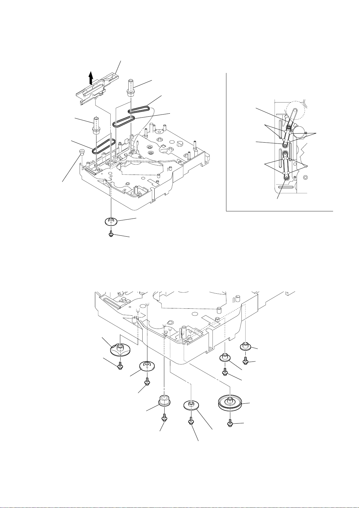
3-19. TIMING BELT (FRONT/REAR)
8)
N
3
slider (mode cam) assy
5
two gears
(center)
6
timing belt
(front)
7
two gears (center)
8
timing belt (rear)
9
timing belt (rear)
When install three timing belts,
its pass under each claws.
timing belt
(rear)
claw
timing belt
(rear)
CX-LZX7
claw
4
gear
(timing)
3-20. CAM (GEAR)
qf cam (gear)
: Note
2
gear (mode cam)
: Note
1
screw
(PTPWH2.6
×
claw
timing belt (front)
Note: Refer to Section 4 assembly (see page 19)
8)
claw
6 gear (mode 5)
qd screw
qs gear(mode cam)
qa screw
(PTPWH2.6 × 8)
0 gear (mode C)
:Note
ote: Refer to assembly
(Section 4).
9 screw
(PTPWH2.6 × 8)
8 gear (mode D)
7 screw (PTPWH2.6 × 8)
5 screw (PTPWH2.6 ×
4 gear (mode 5)
3 screw (PTPWH2.6 × 8)
2 pulley
(mode deceleration)
1 screw(PTPWH2.6 × 8)
17
CX-LZX7
).
3-21. SENSOR BOARD
q; cam (eject lock)
: Note
9 screw
(PTPWH2.6 × 8)
ql harness
qk claw
qd gear (eject lock)
qs cam (BU U/D)
qa screw
(PTPWH2.6 × 8)
8 shaft
(shutter)
7 compression spring
(shutter)
3 screw
(BVTP2.6 × 8)
1 screw
(PTPWH2.6 × 8)
wa SENSOR board
w; screw
(BVTP2.6 × 8)
6 gear (mode A)
5 base (shutter) block
4 two screws
(BVTP2.6 × 8)
2 lever shutter (A)
qh two claws
qj rotary encoder
(S771)
qg screw
(PTPWH2.6 × 8)
qf gear
(mode B)
Note: Refer to Section 4 assembly (see page 19
18
SECTION 4
.
k)
ASSEMBLY
• This set can be assembled in the order shown below.
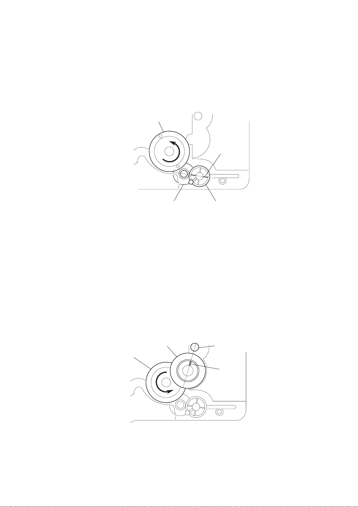
4-1. HOW TO INSTALL THE CAM (EJECT LOCK)
1
Rotate the cam (BU U/D) fully in the direction of arrow.
2
Engage the gear (eject lock) and the gear of the cam (eject loc
aligning the mark with the center of the gear (eject lock).
cam (BU U/D)
CX-LZX7
mark
4-2. HOW TO INSTALL THE CAM (GEAR)
1
Check that the cam (BU U/D) can not be rotated in the direction of arrow
2
Align the mark on the cam (gear) with the boss as shown in the figure
and install the cam (gear).
cam (BU U/D)
gear (eject lock)
– bottom view • front –
cam (gear)
cam (eject lock)
boss
mark
– bottom view • front –
19
CX-LZX7
c
r).
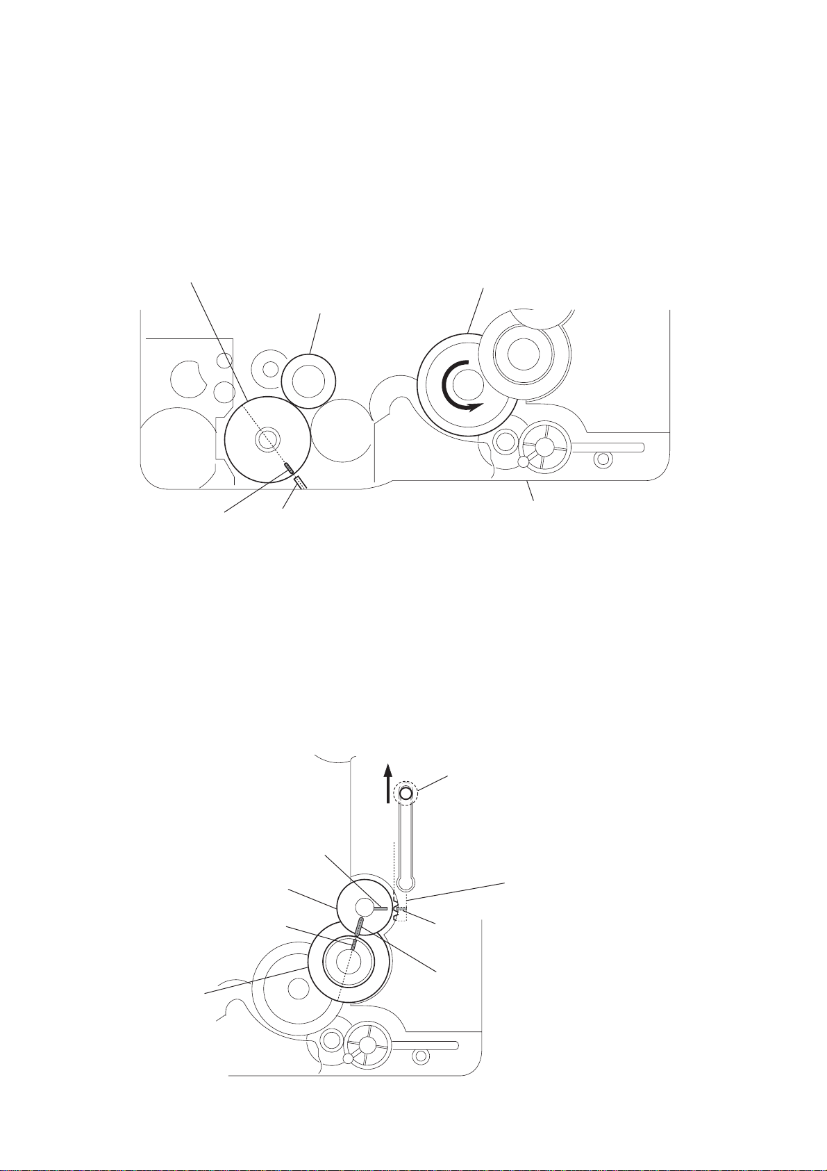
4-3. HOW TO INSTALL THE GEAR (MODE C)
1
Align the mark on the rotary encoder (S771) with the projection of the assy.
2
Check that the cam (BU U/D) can not be rotated in the direction of arrow.
3
Install the gear (
rotary encoder
(S771)
mode
C)
gear (
mode
cam (BU U/D)
C)
mark projection
4-4. HOW TO INSTALL THE GEAR (MODE CAM)
1
Slide the shaft in the direction of arrow.
2
Align mark A on the gear (mode cam) with mark B on the slider (mode cam) assy,
then install the gear (mode cam).
3
Check that mark C on the gear (mode cam) is in alignment with mark D on the cam (gea
mark A
gear (mode cam)
chassis
– bottom view • front –
shaft
slider (mode cam) assy
mark D
am (gear)
– bottom view • front –
mark B
mark C
20
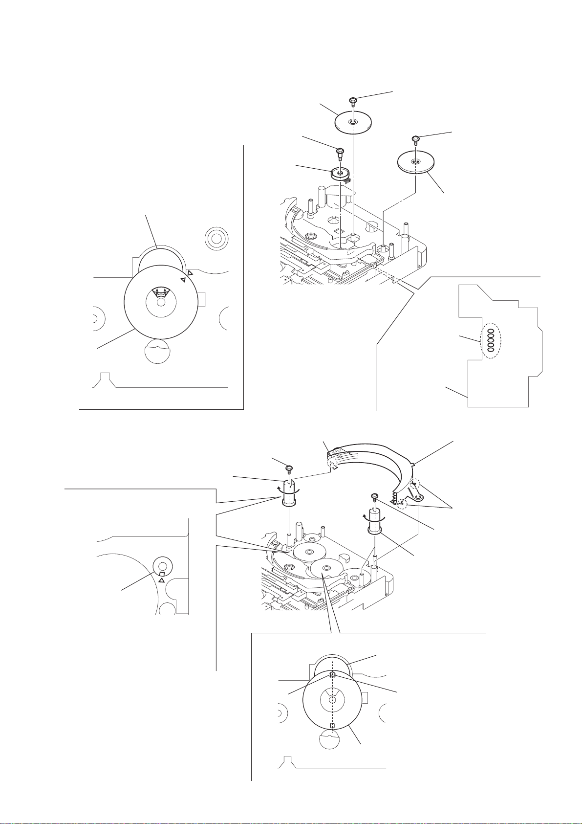
4-5. HOW TO INSTALL THE ROTARY ENCODER (S702), GEAR (STOCKER COMMUNICATION)
)
g
(
c
s
Engage the rotary encoder (S702)
and the gear (stocker communication)
as shown below in the figure.
4 gear
(stocker communication)
3
screw
×
(PWH2
1
6)
rotary encoder
(S702)
5
screw
(PTPWH2.6
×
8)
7
two screws
(PTPWH2.6
CX-LZX7
×
8)
rotary encoder
(S702)
ear
stocker
ommunication)
– rear –
4-6. HOW TO INSTALL THE STOCKER ASSY
3
2
cam
(stocker V)
screw
(PTPWH2.6
×
6 two gears
(stocker communication
2 five
solders
CONNECTOR board
boss
8)
Install the stocker assy
fitting three bosses into the
each groove of cam
then fix by rotating the cam
in the direction of arrow.
boss
5
two screws
(PTPWH2.6
4
two cams
(stocker U/D)
cam
To install three cams, align each groove
of the cam with each f mark on the
chassis as shown in the figure.
screw
– rear –
rotary encoder
(S702)
hole
1
Position the hole on the gear
(stocker communication) on the
screw of the rotary encoder (S702).
gear
(stocker communication)
×
8)
21

CX-LZX7
SECTION 5
TEST MODE
[Cold Reset]
* The cold reset clears all data including preset data stored in the
RAM to initial conditions. Execute this mode when returning
the set to the customer.
Procedure:
1. Press the ?/1 button to turn off the main power.
2. While depressing the i-Bass button, press the ?/1 button.
3. The fluorescent indicator tube does not display any message
and the set is reset.
[Version Display Mode]
*The version of the microcomputer is displayed.
Procedure:
1. Press the ?/1 button to turn the set on.
2. To enter the test mode, press three buttons FUNCTION ,
DISPLAY and i-Bass simultaneously. The version of the
microcomputer is displayed.
[LCD Check]
* All fluorecent segments are tested.
Procedure:
1. Press the ?/1 button to the set on.
2. While depressing the FUNCTION button, Press the DISPLA Y
button.
3. The message “CD TEST” is displayed, the initialization is
performed.
Then all segments of the fluorecent indicator tube are turned on.
[CD Ship Mode]
*This mode moves the optical pick-up to the position durable to
vibration. Use this mode when returning the set to the customer
after repair.
Procedure:
1. Press the ?/1 button to turn the set on.
2. Set the FUNCTION to CD.
3. Press two buttons of Z CD and > simultaneously for more
than two seconds.
4. After a message “MECHA LOCK” is displayed on the
fluorescent indicator tube, the CD ship mode is set and the power
is turned off.
[AM Channel Step 9 kHz/10kHz Selection Mode]
* Either the 9 kHz step or 10 kHz step can be selected for the AM
channel step. (EXCEPT AEP,UK)
Procedure:
1. Set the FUNCTION to AM.
2. While depressing the > button, press the ?/1 button.
3. The channel step is changed over.
[CD Test Mode]
*This mode can run the CD sled motor freely. Use this mode, for
instance, when cleaning the pickup.
Procedure:
1. Press the ?/1 button to turn the set on.
2. While depressing the CD u button, Press the DIRECTION
button. The message “CD TEST” is displayed.
3. With the CD in stop status, press the > button to move the
pickup to outside track, or press the . button to inside
track.
4. When press the CD u button, normal playback is performed.
5. Each time the CD u button is pressed during normal
playback, the tracking servo is switched on or off.
6. To exit this mode, either change to other functions or extract
an AC plug.
[CD Repeat 5 Times Limit Release Mode]
Procedure:
1. Press the ?/1 button to turn the set on.
2. Select the FUNCTION to CD.
3. Press two buttons of > and DIRECTION simultaneously.
4. The repeat all mark blinks and then repeat 5 times limit is
released.
[Disc T ray Lock]
The disc tray lock function for the antitheft of an demonstration
disc in the store is equipped.
Setting Procedure :
1. Press the ?/1 button to turn the set on.
2. Press two buttons of x and Z CD simultaneously for five
seconds.
3. The message “LOCKED” is displayed and the tray is locked.
Releasing Procedure :
1. Press two buttons of x and Z CD simultaneously for five
seconds again.
2. The message “UNLOCKED” is displayed and the tray is
unlocked.
Note : When “LOCKED” is displayed, the tray lock is not released
by turning power on/off with the ?/1 button.
[AMP Test]
*This mode is used to check the function of the amplifier.
Procedure:
1. Press the ?/1 button to turn the set on.
2. While depressing the x button, Press the DISPLAY button.
3. The message “V olume MAX” is displayed, when the VOLUME
knob is rotated clockwise. The message “Volume MIN” is
displayed, when the V OLUME knob is rotated counterclockwise.
4. Each time the BASS or TREBLE knob is turned, the message
“EQ MAX”, “EQ MIN” or “EQ FLAT” is displayed in this
order.
22
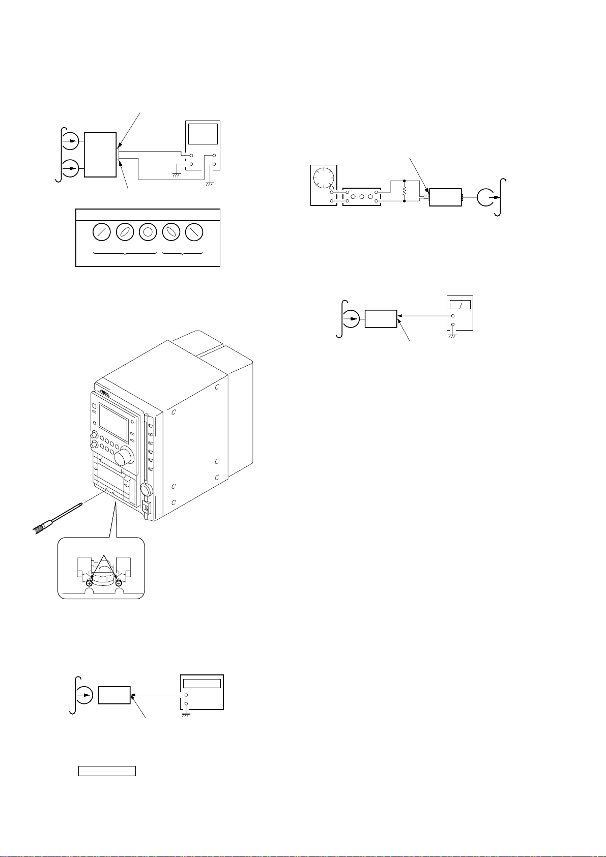
SECTION 6
S
p
n
set
MAIN board
SPEAKER terminal (J201)
L-CH, R-CH
+
–
level meter
test tape
P-4-A100
(10 kHz, – 10 dB)
MECHANICAL ADJUSTMENTS
CX-LZX7
SECTION 7
ELECTRICAL ADJUSTMENTS
• TAPE MECHANISM DECK SECTION
Precaution
1. Clean the following parts with a denatured alcohol-moistened
swab:
record/playback heads pinch rollers
erase head rubber belts
capstan idlers
2. Demagnetize the record/playback head with a head
demagnetizer.
3. Do not use a magnetized screwdriver for the adjustments.
4. After the adjustments, apply suitable locking compound to the
parts adjusted.
5. The adjustments should be performed with the rated power
supply voltage unless otherwise noted.
Torque Measurement
Mode
FWD
FWD
back tension
REV
REV
back tension
FF/REV
FWD tension
REV tension
Torque meter
CQ-102C
CQ-102C
CQ-102RC
CQ-102RC
CQ-201B
CQ-403A
CQ-403R
Meter reading
2.94 – 7.84 mN • m
(30 to 79 g • cm)
(0.42 – 1.11 oz • inch)
0.15 – 0.59 mN • m
2 to 6 g • cm
(0.03 – 0.08 oz • inch)
2.94 – 7.84 mN • m
(30 to 79 g • cm)
(0.42 – 1.11 oz • inch)
2.94 – 7.84 mN • m
(30 to 79 g • cm)
(0.42 – 1.11 oz • inch)
6.86 – 17.64 mN • m
(70 to 179 g • cm)
(0.98 – 2.49 oz • inch)
0.98 mN • m
(10 • cm or more)
(0.14 oz • inch or more)
0.98 mN • m
(10 • cm or more)
(0.14 oz • inch or more)
DECK SECTION
0 dB = 0.775 V
Precaution
1. Demagnetize the record/playback head with a head
demagnetizer.
2. Do not use a magnetized screwdriver for the adjustments.
3. After the adjustments, apply suitable locking compound to the
parts adjust.
4. The adjustments should be performed with the rated power
supply voltage unless otherwise noted.
5. The adjustments should be performed in the order given in this
service manual. (As a general rule, playback circuit adjustment
should be completed before performing recording circuit
adjustment.)
6. The adjustments should be performed for both L-CH and RCH.
7. Switches and controls should be set as follows unless otherwise
specified.
• Test Tape
Tape Signal Used for
P-4-A100 10 kHz, – 10 dB Azimuth Adjustment
WS-48B 3 kHz, 0 dB Tape Speed Check
Record/Playback Head Azimuth Adjustment
Procedure:
1. Mode: Playback
2. Turn the adjustment screw and check output peaks. If the peaks
do not match for L-CH and R-CH, turn the adjustment screw
so that outputs match within 1dB of peak.
Output
level
within
1dB
L-CH
peak
R-CH
peak
within
1dB
Screw
positio
23
L-CH
peak
R-CH
crew
osition
peak
CX-LZX7
t
P
(
e
1)
r
p
)
er
e
A
t
W
(
3. Mode: Playback
MAIN board
est tape
-4-A100
10 kHz, – 10 dB)
L-CH
set
R-CH
in phase 45° 90° 135° 180°
SPEAKER terminal (J20
L-CH
R-CH
waveform of oscilloscope
good
oscilloscop
wrong
H
V
4. After the adjustments, apply suitable locking compound to the
parts adjusted.
Adjustment Location: Record/Playback/Erase Head
Record Bias Adjustment
Procedure:
1. Record mode
MAIN board
AUX IN (J602)
1) 315 Hz
F OSC
2) 10 kHz
attenuator
2. Mode: Playback
i-Bass OFF
BASS 0
TREBLE 0
ecorded
ortion
set
MAIN board speaker terminal (J201
50 mV (–23.8 dB)
600 Ω
set
level met
blank tap
CN-123
+
–
Tape Speed Check
Mode: Playback
adjustment screw
Note: Refer to “3-6. Cassette Panel” (see page 10)
est tape
S-48B
3 kHz, 0 dB)
set
frequency counter
+
–
3. Confirm playback the signal recorded in step 1 become
adjustment level as follows.
Adjustment level: Playback output of 315 Hz to playback output
of 10 kHz: 0 ± 1.0 dB (0 ± 4.5mV).
MAIN board
SPEAKER terminal (J201)
L-CH, R-CH
1. Insert the WS-48B into the deck.
2. Press the TAPE nN button on the deck.
3. Confirm that the frequency counter reads 3,000 ± 90 Hz.
Sample value of Wow and Flutter: 0.3% or less W.RMS (JIS)
(WS-48B)
24
 Loading...