

Sony CXLMN-5 Service manual

CX-LMN5
Power requirements 230 V AC, 50/60 Hz (AEP, UK)
120 V AC, 60 Hz (US, CND, TW)
120 V/220 V/230-240 V AC,
50/60 Hz (E)
220 V AC, 50/60 Hz (KR)
110-240 V AC, 50/60 Hz (TH)
220-240 V AC, 50/60 Hz (SP)
240 V AC, 50/60 Hz (AUS, TW)
MAIN UNIT CX-LMN5
TUNER
AMPLIFIER
CASSETTE DECK
CD PLAYER
GENERAL
Specifications and external appearance are subject to change
without notice.
with ECO mode on: 0.26 W (EXCEPT E)
0.35W (E)
0.25 W (US,CND)
0.26 W (AEP,UK)
0.26 W(TH,KR)
0.35 W(OTHER)
with ECO mode off:15 W (EXCEPT E)
18 W(E)
16 W (US,CND)
15 W (AEP,UK)
18 W (TH,KR)
18 W (OTHER)
FM tuning range 87.5 MHz to 108 MHz
FM usable sensitivity (IHF) 16.8 dBf
FM antenna terminal 75 Ω (unbalanced)
AM tuning range 531 kHz to 1602 kHz (9 kHz Step)
(AEP, UK)
AM usable sensitivity 350 µV/m
AM antenna Loop antenna
Power output Rated: 64 W + 64 W (6 Ω, T. H .D.
1 %, 1 kHz/DIN 45500)
Reference: 80 W + 80 W (6 Ω, T.H . D.
10 %, 1 kHz/DIN 45324)
MUSIC POWER: 220 W + 220 W
Input AUX IN: 1.4 V
Outputs SPEAKERS: 6 Ω or more
PHONES: 32 Ω or more
Track format 4 tracks, 2 channels stereo
Frequency response 100 Hz – 10000 Hz
Recording system AC bias
Heads Recording/playback × 1, erase × 1
Laser Semiconductor laser (λ = 800 nm)
Emission duration: continuous
D/A converter 1 bit dual
Signal-to-noise ratio 85 dB (1 kHz, 0 dB)
Wow and flutter Unmeasurable
Power consumption 85 W (EXCEPT US, CND)
Power consumption in standby mode
Dimensions (w/h/d) Approx. 190 × 277 × 353 mm
Mass Approx. 6.8 kg
Supplied accessories: FM antenna (1)
AM antenna (1)
Speaker cords (2)
Remote commander (1)
Batteries (2)
530 kHz to 1710 kHz (10kHz Step)
(EXCEPT AEP, UK)
531 kHz to 1710 kHz (9kHz Step)
(EXCEPT AEP, UK)
80 W (US, CND)
SERVICE MANUAL
Ver 1.2 2003.09
CX-LMN5 is the Amplifier, CD player, Tape
Deck and Tuner section in XR-MN5.
Model Name Using Similar Mechanism NEW
CD
Section
TAPE
Section
CD Mechanism Type CDM69BV-30CBD64NS
Base Unit Name BU-30CBD64NS
Optical Pick-up Name A-MAX.3
Model Name Using Similar Mechanism NEW
Tape Transport Mechanism T ype CMAL1Z240A
US Model
Canadian Model
AEP Model
UK Model
E Model
Australian Model
9-877-183-03
2003I16-1
© 2003.09
Sony Corporation
Home Audio Company
Published by Sony Engineering Corporation
SPECIFICATIONS
MICRO HI-FI COMPONENT SYSTEM
•Abbreviation
AUS: Australian model.
CND : Canadian model.
SP : Singapore model.
TW : Taiwan model.
KR : Korean model.
TH : Thai model.

CX-LMN5
TABLE OF CONTENTS
1. SERVICING NOTES ······················································· 3
2. GENERAL ·········································································· 4
3. DISASSEMBLY
3-1. Side Panel (L)(R), Top Panel, Back Panel ······················ 7
3-2. CD Mechanism Section ·················································· 7
3-3. Front Panel Section ························································· 8
3-4. FRONT Board································································· 8
3-5. Cassette Deck Mechanism ·············································· 9
3-6. Cassette Panel ································································· 9
3-7. Power Transformer························································ 10
3-8. MAIN Board Section ···················································· 10
3-9. CD Mechanism Deck (CDM69BV-30CBD64NS) ······· 11
3-10. Base Unit Section························································ 11
3-11. Base Unit (BU-30CBD64NS) ····································· 12
3-12. BD Board ···································································· 12
3-13. SW Board, Bracket (TOP) Assy ································· 13
3-14. CONNECTOR Board ················································· 13
3-15. Motor (Stocker) Assy (Stocker)(M761)······················ 14
3-16. Motor (Roller) Assy (Roller)(M781) ·························· 14
3-17. Motor (Mode) Assy (Mode)(M771) ··························· 15
3-18. Rubber Roller (Slider) Assy········································ 15
3-19. Timing Belt (Front/Rear) ············································ 16
3-20. Cam (Gear) ································································· 16
3-21. SENSOR Board ·························································· 17
4. ASSEMBLY
4-1. How to Install the Cam (EJECT LOCK) ············ 18
4-2. How to Install the Cam (GEAR) ························ 18
4-3. How to Install the Gear (MODE C) ··················· 19
4-4. How to Install the Gear (MODE CAM) ············· 19
4-5. How to Install the Rotary Encoder (S702),
Gear (STOCKER COMMUNICATION) ··········· 20
4-6. How to Install the Stocker Assy ························· 20
5. TEST MODE ···································································· 21
6. MECHANICAL ADJUSTMENTS ····························· 22
8. DIAGRAMS······································································ 27
8-1. Block Diagram — BD, Changer Section — ·················28
— Main Section —······························ 29
8-2. Printed Wiring Boards — BD Section — ····················· 30
8-3. Schematic Diagram — BD Section — ························· 31
8-4. Printed Wiring Boards — Changer Section — ············· 32
8-5. Schematic Diagram — Changer Section — ················· 33
8-6. Printed Wiring Boards — Front Section — ·················· 34
8-7. Schematic Diagram — Front Section — ······················ 35
8-8. Printed Wiring Boards — Main Section — ·················· 36
8-9. Schematic Diagram — Main Section 1 — ··················· 37
8-10. Schematic Diagram — Main Section 2 — ················· 38
8-11. Schematic Diagram — Main Section 3 — ················· 39
8-12. Schematic Diagram — Main Section 4 — ················· 40
8-13. Schematic Diagram — Main Section 5 — ················· 41
8-14. Schematic Diagram
— Main Section 6/Power Section — ··············· 42
8-15. Printed Wiring Boards — Power Section — ············· 43
8-16. IC Block Diagrams ····················································· 44
8-17. IC Pin Function Description ······································· 47
9. EXPLODED VIEWS
9-1. Panel Section································································· 49
9-2. Front Section ································································· 50
9-3. Chassis Section ····························································· 51
9-4. CD Mechanism Deck Section 1
(CDM69BV-30CBD64NS) ··········································· 52
9-5. CD Mechanism Deck Section 2
(CDM69BV-30CBD64NS) ··········································· 53
9-6. CD Mechanism Deck Section 3
(CDM69BV-30CBD64NS) ··········································· 54
9-7. CD Mechanism Deck Section 4
(CDM69BV-30CBD64NS) ··········································· 55
9-8. CD Mechanism Deck Section 5
(CDM69BV-30CBD64NS) ··········································· 56
9-9. CD Mechanism Deck Section 6
(CDM69BV-30CBD64NS) ··········································· 57
9-10. CD Mechanism Deck Section 7
(CDM69BV-30CBD64NS) ··········································· 58
9-11. Optical pick-up Section ·············································· 59
7. ELECTRICAL ADJUSTMENTS ······························· 22
SAFETY-RELATED COMPONENT WARNING!!
COMPONENTS IDENTIFIED BY MARK 0 OR DOTTED LINE WITH
MARK 0 ON THE SCHEMATIC DIAGRAMS AND IN THE PARTS
LIST ARE CRITICAL TO SAFE OPERATION. REPLACE THESE
COMPONENTS WITH SONY PARTS WHOSE PART NUMBERS
APPEAR AS SHOWN IN THIS MANUAL OR IN SUPPLEMENTS
PUBLISHED BY SONY.
2
10.ELECTRICAL PARTS LIST ······································· 60
ATTENTION AU COMPOSANT AYANT RAPPORT
À LA SÉCURITÉ!
LES COMPOSANTS IDENTIFÉS PAR UNE MARQUE 0 SUR LES
DIAGRAMMES SCHÉMATIQUES ET LA LISTE DES PIÈCES SONT
CRITIQUES POUR LA SÉCURITÉ DE FONCTIONNEMENT. NE
REMPLACER CES COMPOSANTS QUE PAR DES PIÈSES SONY
DONT LES NUMÉROS SONT DONNÉS DANS CE MANUEL OU
DANS LES SUPPÉMENTS PUBLIÉS PAR SONY.
SECTION 1
r
SERVICING NOTES
CX-LMN5
Notes on chip component replacement
•Never reuse a disconnected chip component.
• Notice that the minus side of a tantalum capacitor may be damaged by heat.
Flexible Circuit Board Repairing
•Keep the temperature of the soldering iron around 270 ˚C during
repairing.
• Do not touch the soldering iron on the same conductor of the
circuit board (within 3 times).
• Be careful not to apply force on the conductor when soldering or
unsoldering.
SAFETY CHECK-OUT
After correcting the original service problem, perform the following
safety check before releasing the set to the customer:
Check the antenna terminals, metal trim, “metallized” knobs, screws,
and all other exposed metal parts for AC leakage.
Check leakage as described below.
LEAKAGE TEST
The AC leakage from any exposed metal part to earth ground and
from all exposed metal parts to any exposed metal part having a
return to chassis, must not exceed 0.5 mA (500 microamperes.).
Leakage current can be measured by any one of three methods.
1. A commercial leakage tester, such as the Simpson 229 or RCA
WT-540A. Follow the manufacturers’ instructions to use these
instruments.
2. A battery-operated AC milliammeter. The Data Precision 245
digital multimeter is suitable for this job.
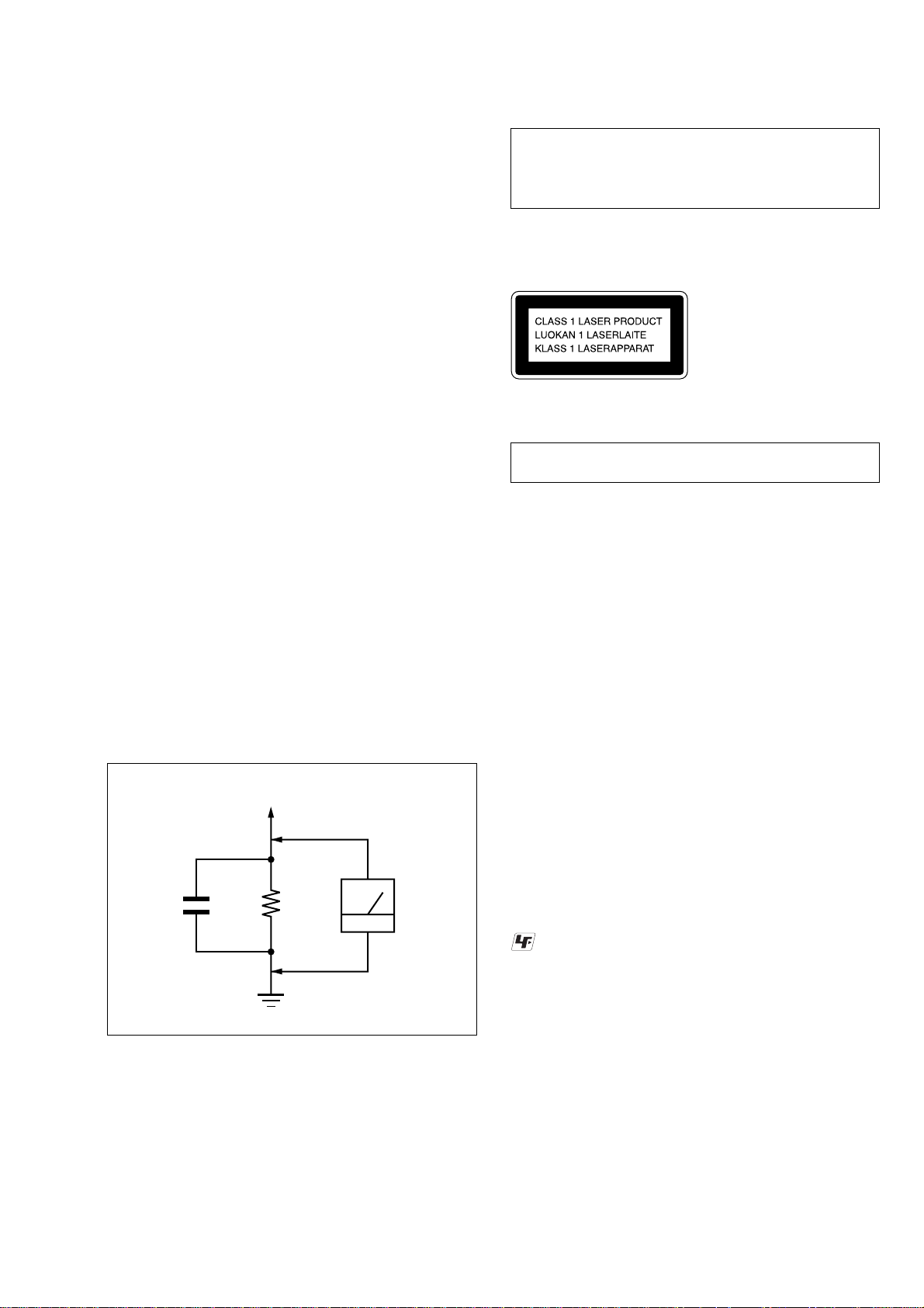
3. Measuring the voltage drop across a resistor by means of a VOM
or battery-operated AC voltmeter. The “limit” indication is 0.75
V, so analog meters must have an accurate low-voltage scale.
The Simpson 250 and Sanwa SH-63Trd are examples of a
passive VOM that is suitable. Nearly all battery operated digital
multimeters that have a 2 V AC range are suitable. (See Fig. A)
CAUTION
Use of controls or adjustments or performance of procedures
other than those specified herein may result in hazardous
radiation exposure.
This appliance is classified as a CLASS 1 LASER product.
The CLASS 1 LASER PRODUCT MARKING is located on
the exterior.
Laser component in this product is capable of emitting radiation
exceeding the limit for Class 1.
NOTES ON HANDLING THE OPTICAL PICK-UP
BLOCK OR BASE UNIT
The laser diode in the optical pick-up block may suffer electrostatic
break-down because of the potential difference generated by the
charged electrostatic load, etc. on clothing and the human body.
During repair, pay attention to electrostatic break-down and also
use the procedure in the printed matter which is included in the
repair parts.
The flexible board is easily damaged and should be handled with
care.
NOTES ON LASER DIODE EMISSION CHECK
The laser beam on this model is concentrated so as to be focused on
the disc reflective surface by the objective lens in the optical pickup block. Therefore, when checking the laser diode emission,
observe from more than 30 cm away from the objective lens.
To Exposed Metal
Parts on Set
1.5 k
0.15 µF
Fig. A. Using an AC voltmeter to check AC leakage.
Ω
Earth Ground
AC
voltmete
(0.75 V)
LASER DIODE AND FOCUS SEARCH OPERATION
CHECK
Carry out the “S curve check” in “CD section adjustment” and check
that the S curve waveforms is output three times.
UNLEADED SOLDER
Boards requiring use of unleaded solder are printed with the leadfree mark (LF) indicating the solder contains no lead.
(Caution: Some printed circuit boards may not come printed with
the lead free mark due to their particular size)
: LEAD FREE MARK
Unleaded solder has the following characteristics.
• Unleaded solder melts at a temperature about 40 ˚C higher than
ordinary solder.
Ordinary soldering irons can be used but the iron tip has to be
applied to the solder joint for a slightly longer time.
Soldering irons using a temperature regulator should be set to
about 350 ˚C .
Caution: The printed pattern (copper foil) may peel away if the
heated tip is applied for too long, so be careful!
• Strong viscosity
Unleaded solder is more viscous (sticky, less prone to flow) than
ordinary solder so use caution not to let solder bridges occur such
as on IC pins, etc.
• Usable with ordinary solder
It is best to use only unleaded solder but unleaded solder may
also be added to ordinary solder.
3
CX-LMN5
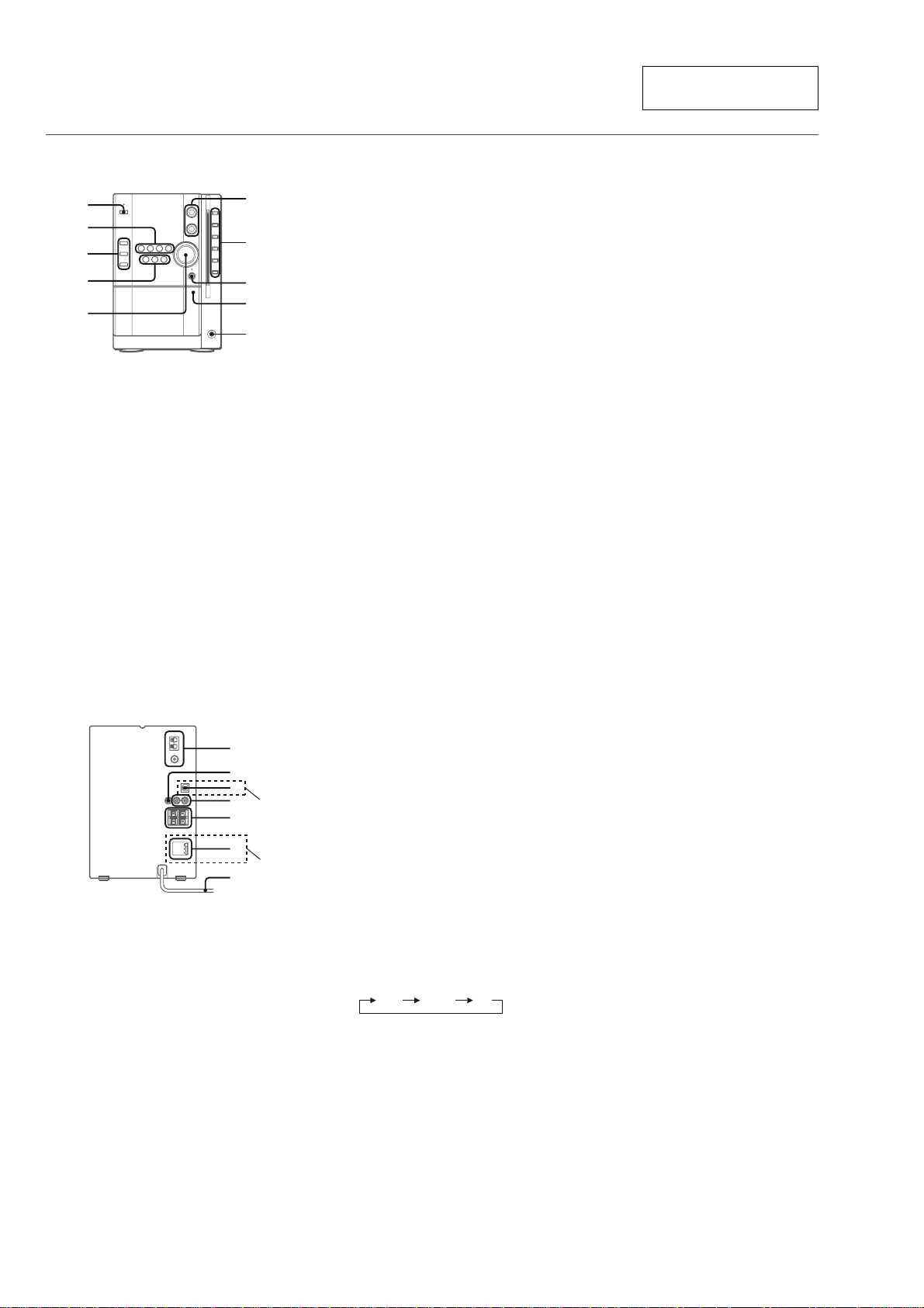
PARTS AND CONTROLS
Main unit: front
Refer to the pages indicated in parentheses for details.
1
2
3
4
5
1 POWER 6STANDBY/ON (8)
Switches the unit on and off (standby).
2 ECD (8, 10-12)
Starts and pauses CD play.
TUNER/BAND (8, 14)
Selects tuner function and the tuner band.
dTAPE (REC MUTING) (8, 17, 19)
Starts playback and changes the playback side.
Also used to enter 4-second blank spaces during
recording.
AUX (8)
Selects the function of external equipment connected to
AUX IN jacks.
6
7
8
9
0
SECTION 2
GENERAL
3 ECO/RDS (8, 14-16)
Sets the ECO mode on or off.
Tuner: Activates RDS features.
SYNCHRO REC (18)
Starts recording and CD play simultaneously.
REC START/REC PAUSE (18-20)
Starts and pauses recording.
4 s (10-12, 17, 18, 20)
CD and Tape: stops playback.
Tuner: clears a preset station.
TUNING f/r-, +t/g(8,10-12,
14, 17, 21, 22)
CD: skips to a previous or a succeeding track when
pressed, searches a track in fast forward or reverse
playback when held down.
Tape: rewinds or fast forwards the tape.
Tuner: manually tunes up or down within the band.
5 VOLUME (9)
Adjusts the volume.
6 TREBLE (9)
Adjusts the treble level.
BASS (9)
Adjusts the bass level.
7 zCD EJECT (10, 12)
Ejects the disc(s).
CD slot buttons (1-5) (8, 10-12)
Selects a disc slot.
Starts CD play for one desired disc.
This section is extracted
from instruction manual.
8 i-Bass/DEMO (4, 9)
Produces rich and clear low frequency sound.
Switches DEMO on and off while the unit is turned off.
9 PUSH EJECTz (17-19)
Opens or closes the cassette holder.
0 PHONES jack
Plug in optional headphones set with a stereo mini plug
(ø3.5 mm). Speaker output is cancelled.
Main unit: rear
Refer to the pages indicated in parentheses for details.
1
2
3
4
(AEP,UK)
5
120V
230-240V
220V
7
6
(E)
1 AM LOOP jack and FM 75 terminal (4)
Plug in the supplied AM and FM antennas.
2 SUB WOOFER3 jack
Connect optional powered sub woofer with a built-in
amplifier to the jack.
3 DIGITAL OUT (OPTICAL) jack (AEP, UK)
CD digital sound signals can be output through this jack.
Use an optical cable to connect digital audio equipment.
Fit an optical cable plug in the DIGITAL OUT (OPTICAL)
jack and push it to connect.
4 AUX IN jacks
Accept analogue sound signals from external equipment.
Connect external equipment using an optional connecting
cable with RCA phono plugs (red plug to R jack, white
plug to L jack). Refer also to the operating instructions
for your equipment.
To switch function to external input, press AUX.
To change a source name in the display of the
AUX function.
Hold down AUX and press POWER while the power is
on.
AUX VIDEO TV
5 SPEAKERS3 terminals (4)
Connect the speaker cords of the supplied speakers.
6 AC power cord (4)
7 VOLTAGE SELECTOR (E)
120 V/220 V/230-240 V AC,50/60Hz
4

CX-LMN5
Remote commander
Refer to the pages indicated in parentheses for details.
1
2
3
4
5
6
7
Buttons with the same or similar names on the main unit
basically have the same function.
1 POWER (8)
2 1–10/0, >10 (10-12, 15, 19, 20)
CD: selects a track of the specified number.
Tuner: tunes in the station with the specified preset
number.
The numbered buttons take on these functions when pressed with
SHIFT held down
CLOCK (8)
Selects clock mode.
TIMER (21, 22)
Selects timer mode.
MUTING (9)
To turn off the sound temporarily.
:
8
9
0
!
@
#
TUNER MODE (15)
Switches between stereo or monaural FM reception.
REV MODE (17, 18, 22)
Selects a reverse mode.
DISC/ALBUM (12)
Selects disc mode or album mode on an MP3-CD.
CD EDIT/CHECK (19, 20)
Selects edited CD recording.
3 SHUFFLE/PROGRAM (11)
Selects shuffle or programmed CD playback mode.
REPEAT (11)
Selects repeat CD playback mode.
4 ALBUM/PRESETN,M (12, 15)
MP3-CD:Skips to a previous or succeeding album.
Tuner: Tunes in a preset station.
f/r,t/g (8, 10-12, 14, 17, 21,
22)
ENTER (8, 14, 15, 21, 22)
Determines the mode.
Stores the received station to preset.
5 ECD (8, 10-12)
TUNER/BAND (8, 14)
dTAPE (8, 17)
AUX (8)
6 DISPLAY (10, 12)
Changes the display in CD playback mode.
DIMMER (8)
Adjusts the display window brightness.
SLEEP (21)
Selects sleep-timer mode.
7 SHIFT
Hold down when pressing a numbered button to change
its function to that printed above the number.
8 DISC SELECT (10, 12)
Selects a desired CD slot.
9 CLEAR (11, 15, 21, 22)
CD: Clears a CD program
Tuner: Clears a preset station.
0 i-Bass (9)
TONE (9)
Selects the bass or treble adjusting mode.
! s (10-12, 17, 18, 20)
@ FUNCTION (18-20)
Switches the active function among TAPE, TUNER, AUX
(VIDEO or TV) and CD.
# VOLUME +,- (9)
ADJUSTMENTS BEFORE OPERATION
POWER
6STANDBY/ON
∗ ECO/RDS
m ,M
∗ AEP,UK : ECO/RDS
EXCEPT
AEP,UK : ECO
Power
Turning the unit on
Press POWER 6STANDBY/ON (POWER on the remote ).
Alternatively, press dTAPE, TUNER/BAND, AUX, ECD
or one of the CD slot buttons (1-5). Playback will start
automatically if a disc or tape is loaded.
Turning the unit off
Press POWER 6STANDBY/ON again.
The unit goes into standby.
Dimmer
The display window brightness can be selected.
Press DIMMER on the remote.
Each press of the button changes between darker and brighter.
u CD,
TUNER/
BAND,
Y TAPE,
AUX
POWER
CLOCK
u CD,
TUNER/
BAND,
Y TAPE,
AUX
SHIFT
DIMMER
ECO mode
Reduces power consumption in standby mode with the following
operations.
Press ECO/RDS. (AEP,UK : ECO/RDS EXCEPT AEP,UK : ECO)
Each press of the button changes the mode as follows;
ECO ON: Power economizing mode is activated.
When the unit turns off, everything on the display clears and
only the red indicator above POWER lights to show that the
power is being supplied.
ECO OFF: Power economizing mode is cancelled.
When the unit turns off, the clock display appears.
Initial mode is ECO OFF.
Standby power consumption
ECO ON: 0.26 W
ECO OFF: 15 W
ENTER
m ,M
Setting the clock
1
In stop mode, hold down SHIFT and press CLOCK
on the remote.
Go to step 3 when the hour of the clock display flashes.
2
Within 6 seconds, press ENTER.
The hour flashes in the display.
3
Press f or g to set the hour , then press
ENTER.
4
Press f or g to set the minute.
Each press changes the time in 1-minute steps.
5
Press ENTER.
The time display stops flashing and the clock starts from
00 seconds.
To display the time while the power is on
Hold down SHIFT and press CLOCK on the remote.
The time will be displayed for 6 seconds.
If " " appears when the unit is turned off
- -:- -
There has been a power interruption. Reset the clock.
5

CX-LMN5
• This set can be disassembled in the order shown below.
SET
SECTION 3
DISASSEMBLY
SIDE PANEL (L) (R), TOP PANEL,
BACK PANEL
CD MECHANISM SECTION FRONT PANEL SECTION
CD MECHANISM DECK
(CDM69BV-30CBD64NS)
BASE UNIT SECTION
BASE UNIT
(BU-30CBD64NS)
BD BOARD
CASSETTE PANEL
FRONT BOARD CASSETTE DECK MECHANISM
SW BOARD,
BRACKET (TOP) ASSY
MOTOR (ROLLER)
ASSY (ROLLER) (M781)
POWER TRANSFORMER
MOTOR (STOCKER)
ASSY (STOCKER) (M761)
RUBBER ROLLER
(SLIDER) ASSY
TIMING BELT
(FRONT/REAR)
MAIN BOARD SECTION
CONNECTOR BOARD
MOTOR (MODE)
ASSY (MODE) (M771)
CAM (GEAR)
SENSOR BOARD
6
Note: Follow the disassembly procedure in the numerical order given.
n
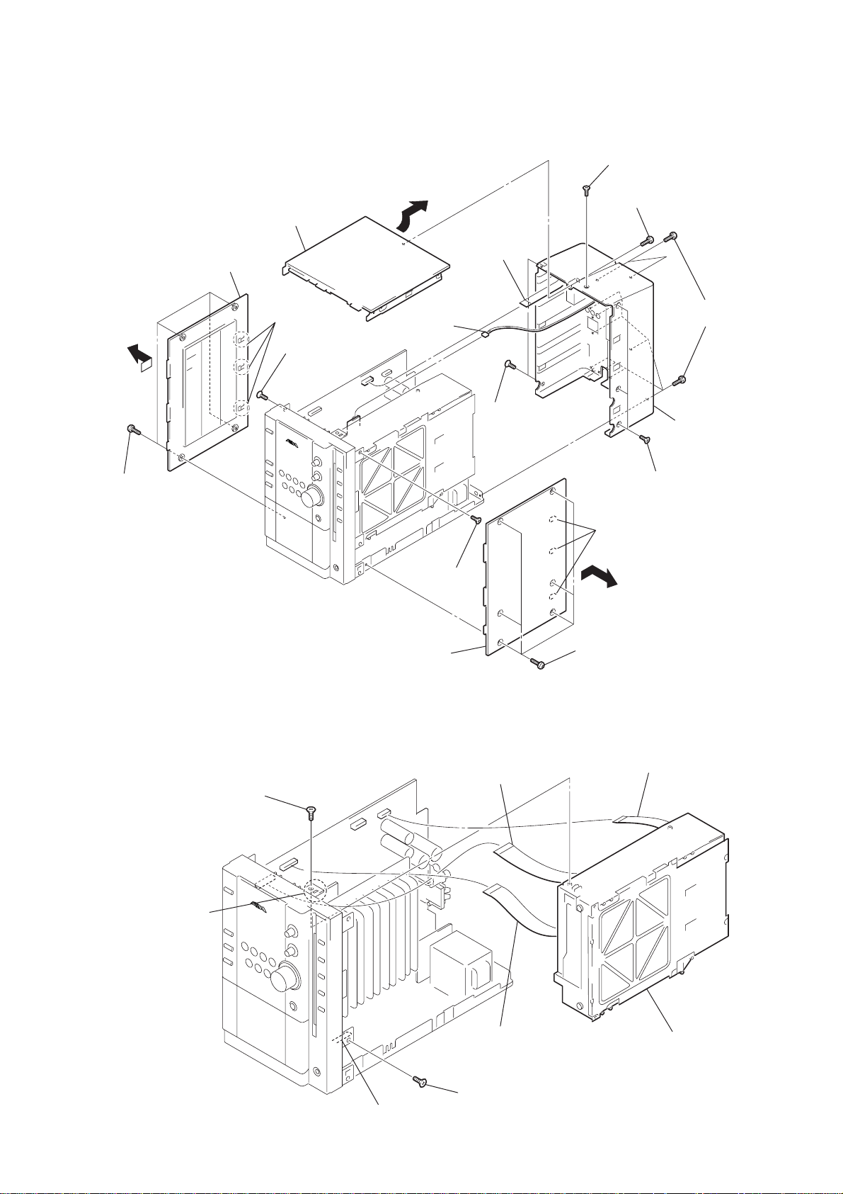
3-1. Side Panel (L)(R), Top Panel, Back Panel
q;
top panel
3
side panel (L)
2
three claws
9
screw
(QT2+3
×
10)
qa
connector
(CN293)
qh
w
ire (flat type)
15p /11P
(CN602)
qs
two screws
×
(QT2+3
10)
qf
screw
(+BVTP3
7
screw (+BVTP3 × 10)
qg
×
10)
ten screws
(+BVTP3
qj
back panel
CX-LMN5
×
10)
1
four screws
(+BVTP3
×
10)
3-2. CD Mechanism Section
4
screw
×
(QT2+3
10)
8
6
side panel (R)
screw
(QT2+3
2
27p (CN901)
×
10)
w
ire (flat type)
5
three claws
4
six screws
(+BVTP3
3
11p (CN601)
qd
three screws
(QT2+3
×
10)
w
ire (flat type)
×
10)
7
claw
6
claw
1
w
ire (flat type)
23p (CN902)
5
screw
×
(QT2+3
10)
8
CD mechanism sectio
7
CX-LMN5
)
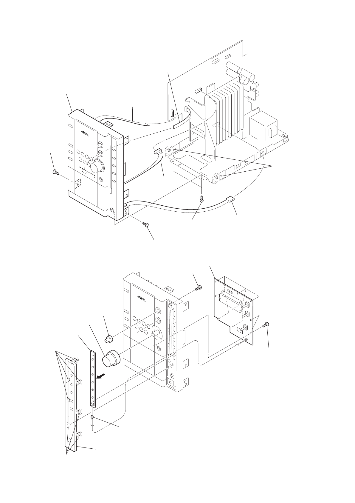
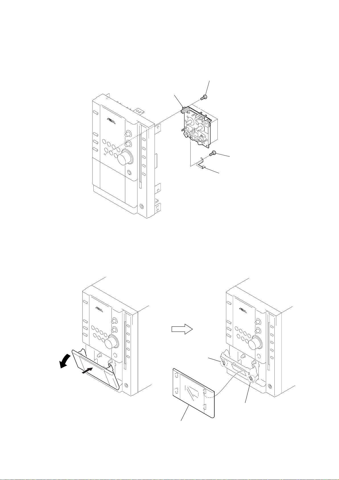
3-3. Front Panel Section
9
front panel section
7
screw
×
(QT2+3
10)
2
w
ire (flat type)
cassette deck mechanism
8p (
1
w
ire (flat type)
17p (CN904)
3
connector
(CN302)
)
8
two claws
3-4. FRONT Board
6
CD-KEY board
2
four claws
8
knob (VOL)
7
two knobs (BT)
6
screw
(QT2+3
1
screw
(+BVTP3
5
two screws
(+BVTP3
×
10)
×
10)
×
10)
q;
FRONT board
4
connector
(CN201)
9
nine screws
(+BVTP3
×
10
5
connector
(CN907)
4
panel (CD)
3
three claws
8
3-5. Cassette Deck Mechanism
)
4
cassette deck mechanism
3
three screws
(+BVTP3
×
10)
2
1
screw
(+BVTP3
shield (DECK)
CX-LMN5
×
10
3-6. Cassette Panel
2
1
3
claw
3
claw
4
cassette panel
9
CX-LMN5
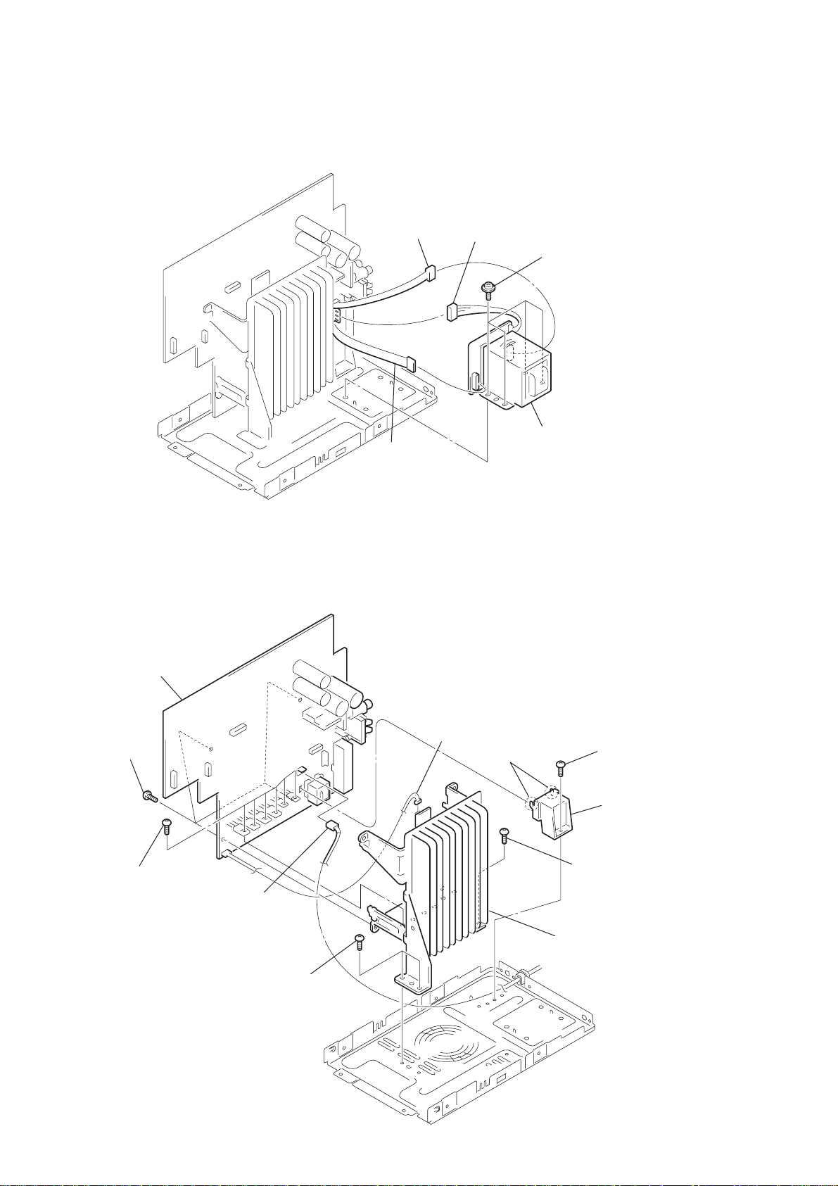
r
)
3-7. Power Transformer
4
connector
(CN256)
2
connector
(CN257)
3
connector
(CN252/ 254)
1
four s-screws
(ITC +4- 10R)
5
power transforme
3-8. MAIN Board Section
qa
MAIN board
9
four s-screws
(IT3B +3 - 8CU)
8
six screws
(+BVTP3
×
10)
1
connector
(CN202)
6
two screws
(BVIT3B+3- 8R W/O)
7
connector
(CN294)
3
two claws
2
screw
(BVIT3B+3- 8R W/O
4
holder (pwb.PT)
5
screw
(BVIT3B+3- 8R W/O)
q;
heat sink assy (MAIN)
10

3-9. CD Mechanism Deck (CDM69BV-30CBD64NS)
)
)
3
four screws
(+BVTP3
4
CD mechanism deck
(CDM69BV-30CBD64NS)
×
10)
1
three screws
(QT2+3
2
holder(CD B
×
CX-LMN5
10)
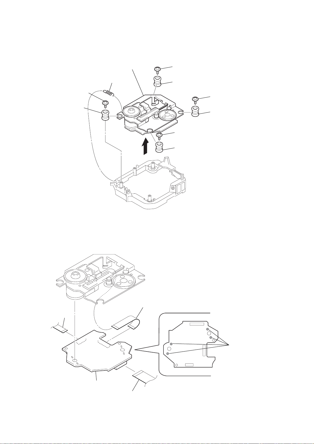
3-10. Base Unit Section
4
boss
2
screw
(+PTPWH) (M2) (DIA. 7)
3
boss
1
floating
screw
(DIA. 12
7
base unit section
5
boss
6
boss
11
CX-LMN5
r
3-11. Base Unit (BU-30CBD64NS)
qa
1
tension spring (BU30-1)
5
floating screw
(+PTPWHM2.6
q;
vibration proof rubbers
×
6)
base unit (BU-30CBD64NS)
6
4
floating screw
(+PTPWHM2.6
9
vibration proof rubber
2
floating screw
(+PTPWHM2.6
7
vibration proof rubber
×
6)
3
floating screw
(+PTPWHM2.6
8
vibration proof rubber
×
6)
×
6)
3-12. BD Board
2
wire (flat type) (11 core)
5
BD board
4
wire (flat type) (16 core)
3
Remove the solde
(four portions).
12
1
wire (flat type) (23 core)

3-13. SW Board, Bracket (TOP) Assy
)
)
3
SW board (2)
1
four
screws
(BTP2.6
×
6)
2
SW board (1)
7
bracket (top) assy
4
SW board (3)
5
SW board (4)
6
six screws
(BVTP2.6
×
CX-LMN5
8
3-14. CONNECTOR Board
– bottom view –
CONNECTOR board
5
connector
(CN703)
4
connector
(CN710)
3
6
CONNECTOR board
2
four screws
(BVTP2.6
×
8
1
Remove five solders.
13
CX-LMN5
s
d
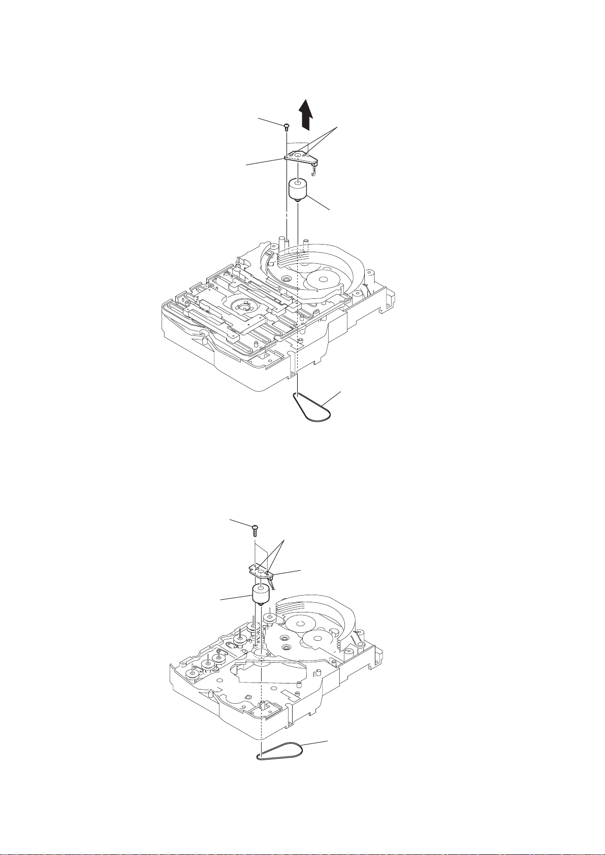
3-15. Motor (Stocker) Assy (Stocker)(M761)
3
two screws
(BVTP2.6
5
stocker motor board
×
4
8)
2
Remove two solder
6
motor (stocker) assy
(stocker) (M761)
1
belt (stocker)
3-16. Motor (Roller) Assy (Roller)(M781)
3
two screws
5
motor (roller) assy
(roller)(M781)
2
Remove two solders.
4
ROLLER MOTOR
1
belt (roller V)
boar
14
3-17. Motor (Mode) Assy (Mode)(M771)
)
1
Remove five solders
of rotary encoder.
MODE MOTOR
board
2
Remove two solders
of motor (M771)
3
two screws
(BVTP2.6
×
8)
4
MODE MOTOR board
6
motor (mode) assy
(mode) (M771)
CX-LMN5
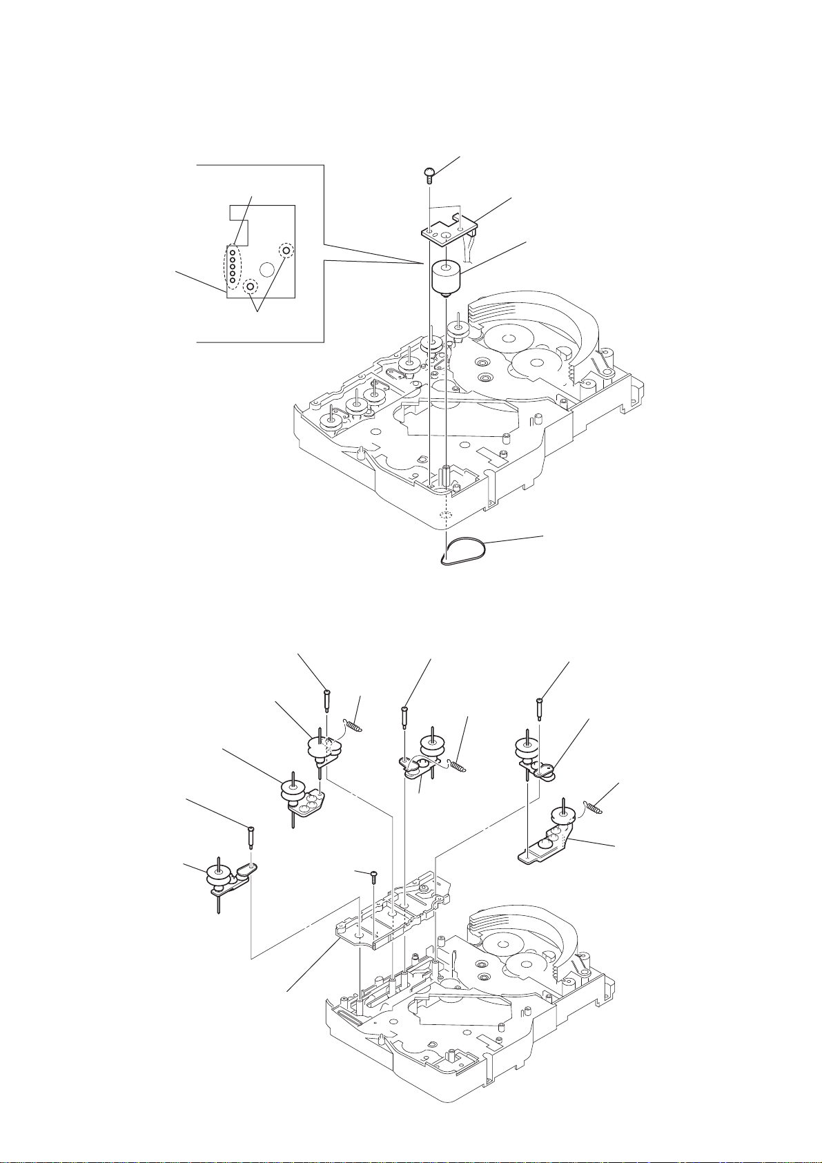
3-18. Rubber Roller (Slider) Assy
8
step screw
0
rubber roller
(slider 4) assy
qa
rubber roller
(slider 2) assy
qs
step screw
qd
rubber roller
(slider 1) assy
qf
screw
(BVTP2.6
9
×
tension
spring
(slider 2)
8)
5
step screw
6
tension spring
(base slider 4)
7
rubber roller
(slider 1) assy
5
belt (mode V)
1
step screw
2
rubber roller
(slider S) assy
3
4
tension spring
(base slider 5
rubber roller
(slider 5) assy
qg
sub chassis
15
CX-LMN5
)
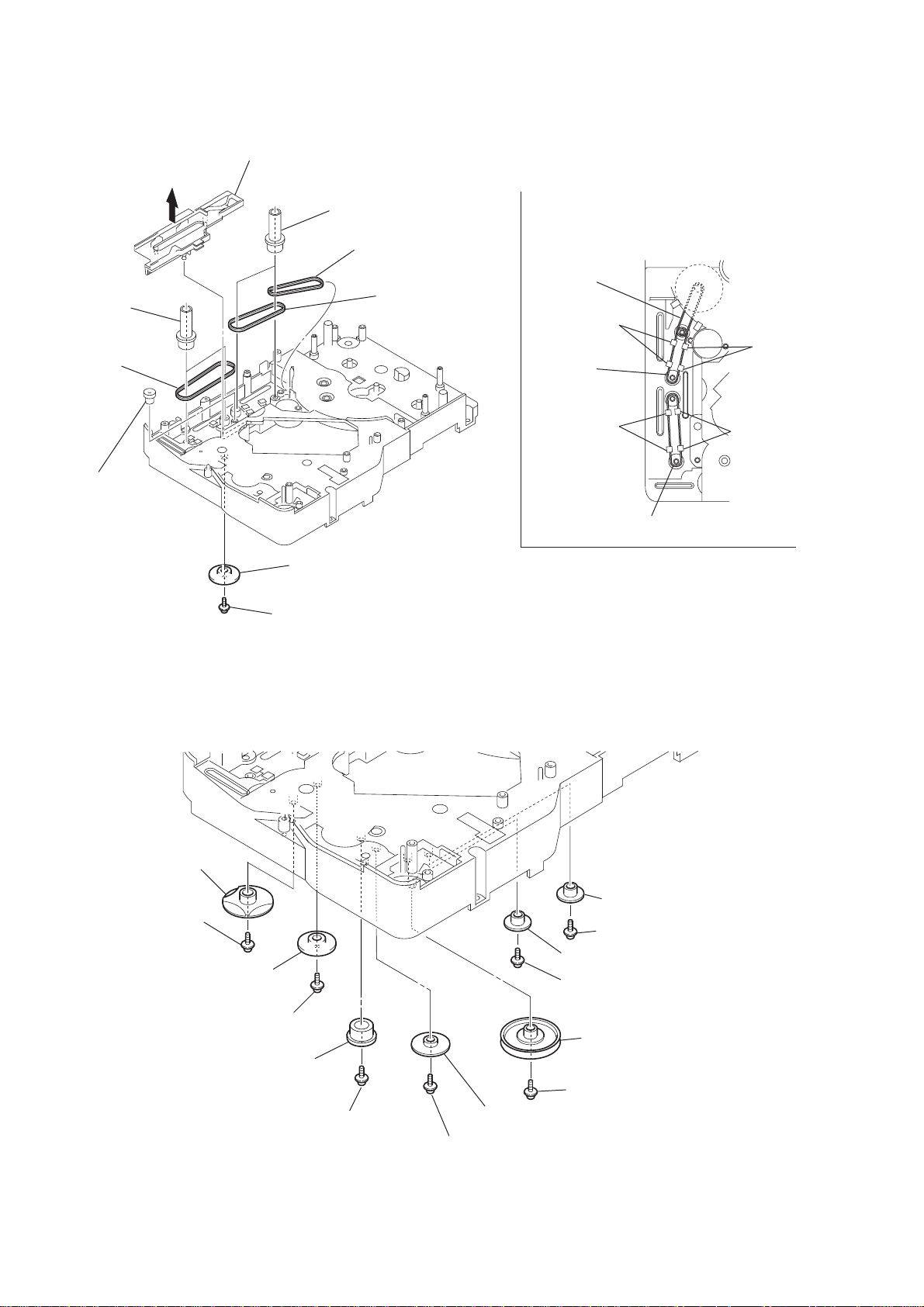
3-19. Timing Belt (Front/Rear)
3
5
two gears
(center)
6
timing belt
(front)
slider (mode cam) assy
7
two gears (center)
8
timing belt (rear)
9
timing belt (rear)
When install three timing belts,
its pass under each claws.
timing belt
(rear)
claw
timing belt
(rear)
claw
4
gear
(timing)
3-20. Cam (Gear)
qf
cam (gear)
: Note
2
gear (mode cam)
: Note
1
screw
(PTPWH2.6
×
claw
timing belt (front)
Note: Refer to assembly (Section 4)
8)
claw
16
qd
screw
qs
gear(mode cam)
qa
screw
(PTPWH2.6
0
Note: Refer to assembly
(Section 4).
×
8)
gear (mode C)
:Note
9
screw
(PTPWH2.6
6
gear (mode 5)
5
screw (PTPWH2.6 × 8
4
gear (mode 5)
3
screw (PTPWH2.6 × 8)
2
pulley
(mode deceleration)
1
screw(PTPWH2.6 × 8)
8
gear (mode D)
×
8)
7
screw (PTPWH2.6 × 8)
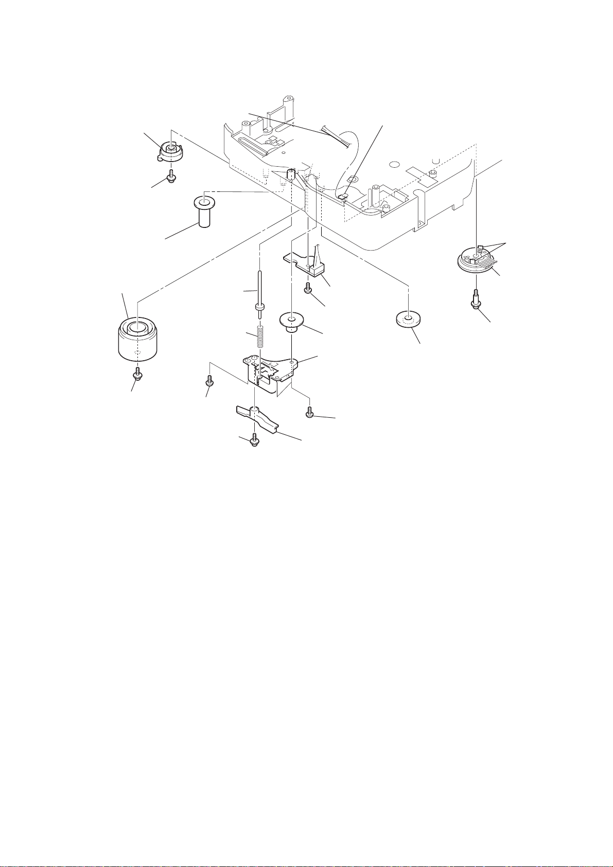
3-21. SENSOR Board
ql
harness
qd
gear (eject lock)
q;
cam (eject lock)
: Note
qh
two claws
qj
rotary encoder
(S771)
qf
gear
(mode B)
w;
screw
(BVTP2.6
×
8)
qg
screw
(PTPWH2.6
×
8)
wa
SENSOR board
8
shaft
(shutter)
7
compression spring
(shutter)
qs
cam (BU U/D)
qa
screw
(PTPWH2.6
×
8)
3
screw
(BVTP2.6
×
8)
1
screw
(PTPWH2.6
×
8)
4
two screws
(BVTP2.6
×
8)
2
lever shutter (A)
5
base (shutter) block
6
gear (mode A)
9
screw
(PTPWH2.6
×
8)
qk
claw
Note: Refer to assembly (Section 4).
CX-LMN5
17

CX-LMN5
• This set can be assembled in the order shown below.
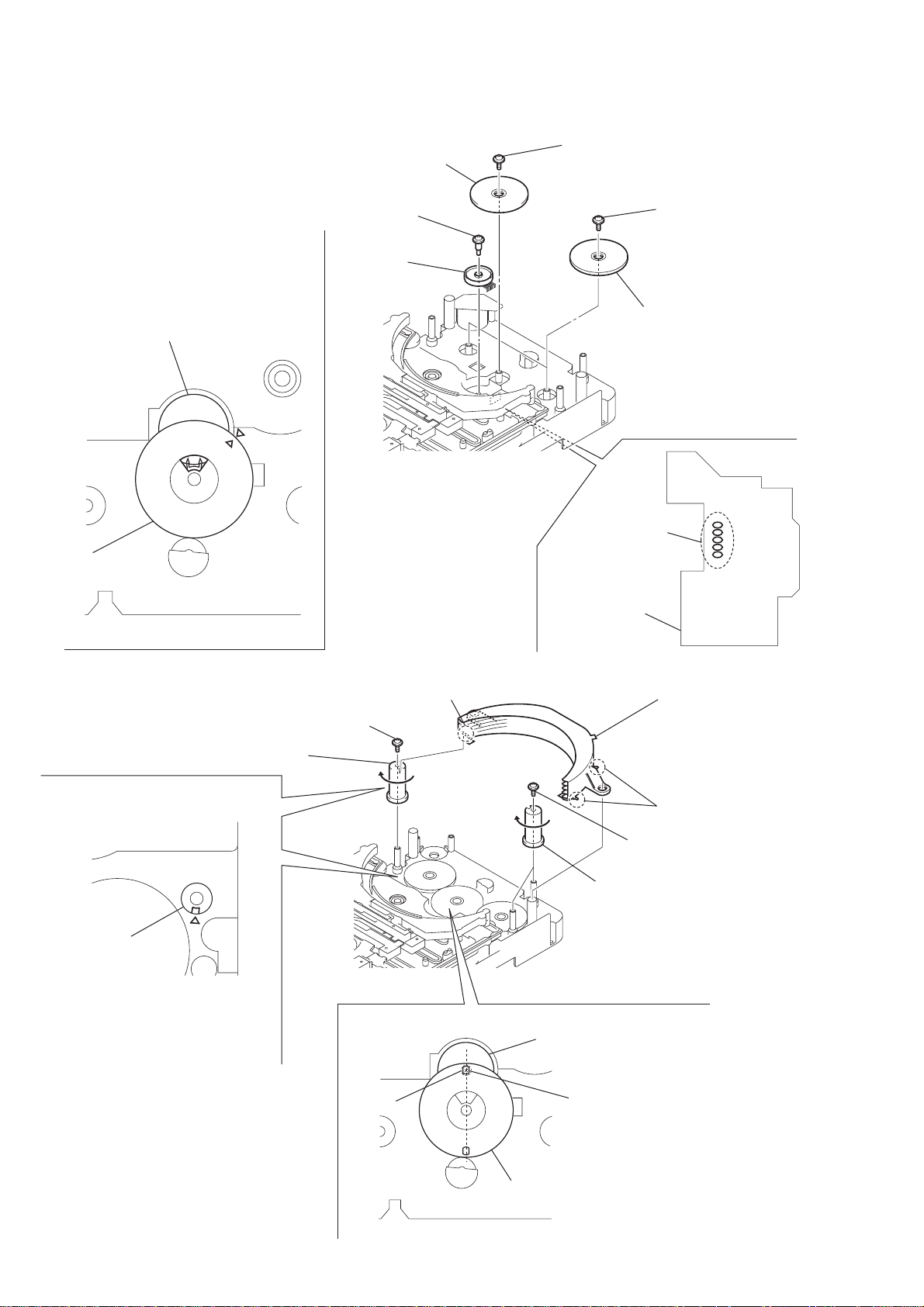
4-1. How to Install the Cam (EJECT LOCK)
1
Rotate the cam (BU U/D) fully in the direction of arrow.
2
Engage the gear (eject lock) and the gear of the cam (eject lock)
aligning the mark with the center of the gear (eject lock).
cam (BU U/D)
SECTION 4
ASSEMBLY
mark
4-2. How to Install the Cam (GEAR)
1
Check that the cam (BU U/D) can not be rotated in the direction of arrow.
2
Align the mark on the cam (gear) with the boss as shown in the figure
and install the cam (gear).
cam (BU U/D)
gear (eject lock)
– bottom view • front –
cam (gear)
cam (eject lock)
boss
mark
18
– bottom view • front –

4-3. How to Install the Gear (MODE C)
1
Align the mark on the rotary encoder (S771) with the projection of the assy.
2
Check that the cam (BU U/D) can not be rotated in the direction of arrow.
3
Install the gear (
rotary encoder
(S771)
mode
C)
gear (
mode
CX-LMN5
cam (BU U/D)
C)
mark projection
4-4. How to Install the Gear (MODE CAM)
1
Slide the shaft in the direction of arrow.
2
Align mark A on the gear (mode cam) with mark B on the slider (mode cam) assy,
then install the gear (mode cam).
3
Check that mark C on the gear (mode cam) is in alignment with mark D on the cam (gear).
mark
gear (mode cam)
chassis
– bottom view • front –
shaft
A
slider (mode cam) assy
cam (gear)
mark
D
– bottom view • front –
mark
mark
B
C
19
CX-LMN5
4-5. How to Install the Rotary Encoder (S702), Gear (STOCKER COMMUNICATION)
4
Engage the rotary encoder (S702)
and the gear (stocker communication)
as shown below in the figure.
rotary encoder
(S702)
gear
(stocker communication)
3
screw
×
(PWH2
1
6)
rotary encoder
(S702)
5
screw
(PTPWH2.6
×
8)
7
two screws
(PTPWH2.6
6
two gears
(stocker communication)
×
8)
gear
(stocker
communication)
– rear –
4-6. How to Install the Stocker Assy
3
screw
(PTPWH2.6
2
cam
(stocker V)
cam
×
2
five
solders
CONNECTOR board
boss
8)
4
two cams
(stocker U/D)
Install the stocker assy
fitting three bosses into the
each groove of cam
then fix by rotating the cams
in the direction of arrow.
boss
5
two screws
(PTPWH2.6
×
8)
To install three cams, align each groove
of the cam with each
chassis as shown in the figure.
f
mark on the
20
screw
– rear –
rotary encoder
(S702)
hole
1
Position the hole on the gear
(stocker communication) on the
screw of the rotary encoder (S702).
gear
(stocker communication)

SECTION 5
TEST MODE
CX-LMN5
[Cold Reset]
* The cold reset clears all data including preset data stored in the
RAM to initial conditions. Execute this mode when returning
the set to the customer.
Procedure:
1. Press the POWER button to turn off the main power.
2. While depressing the x button, press the POWER button.
3. The fluorescent indicator tube does not display any message
and the set is reset.
[Version Display Mode]
*The version of the microcomputer is displayed.
Procedure:
1. Press the POWER button to turn the set on.
2. To enter the test mode, press two buttons x and POWER
simultaneously for more than five seconds. The version of the
microcomputer is displayed.
[FL Tube Check]
* All fluorecent segments are tested.
Procedure:
1. Insert a disc, and extract an AC plug.
2. While depressing the u (CD) button, insert an AC plug to
enter the test mode.
3. The message “CD TEST” is displayed, the initialization is
performed.
Then all segments of the fluorecent indicator tube are turned on.
[CD Ship Mode]
*This mode moves the optical pick-up to the position durable to
vibration. Use this mode when returning the set to the customer
after repair.
Procedure:
1. Press the POWER button to turn the set on.
2. Set the FUNCTION to CD.
3. Press the x button for more than five seconds.
4. After a message “MECHA LOCK” is displayed on the
fluorescent indicator tube, the CD ship mode is set and the power
is turned off.
[AM Channel Step 9 kHz/10kHz Selection Mode]
* Either the 9 kHz step or 10 kHz step can be selected for the AM
channel step. (EXCEPT AEP,UK)
Procedure:
1. Set the FUNCTION to AM.
2. While depressing the TUNER button, press the POWER
button.
3. The channel step is changed over.
[CD Test Mode]
*This mode can run the CD sled motor freely. Use this mode, for
instance, when cleaning the pickup.
Procedure:
1. Extract an AC plug.
2. While depressing the u (CD) button, insert an AC plug to
enter the CD test mode. The message “CD TEST” is displayed.
3. With the CD in stop status, press the > button to move the
pickup to outside track, or press the . button to inside
track.
4. When press the u (CD) button, normal playback is
performed.
5. Each time the u (CD) button is pressed during normal
playback, the tracking servo is switched on or off.
6. To exit this mode, either change to other functions or extract
an AC plug.
[CD Repeat 5 Times Limit Release Mode]
Procedure:
1. Press the POWER button to turn the set on.
2. Select the FUNCTION to CD.
3. Press two buttons of > and u (CD) simultaneously.
4. The repeat all mark blinks and then repeat 5 times limit is
released.
[Disc Tray Lock]
The disc tray lock function for the antitheft of an demonstration
disc in the store is equipped.
Setting Procedure :
1. Press the POWER button to turn the set on.
2. Press two buttons of x and Z (CD EJECT) simultaneously
for five seconds.
3. The message “LOCKED” is displayed and the tray is locked.
Releasing Procedure :
1. Press two buttons of x and Z (CD EJECT) simultaneously
for five seconds again.
2. The message “UNLOCKED” is displayed and the tray is
unlocked.
Note : When “LOCKED” is displayed, the tray lock is not released
by turning power on/off with the POWER button.
[AMP Test]
*This mode is used to check the function of the amplifier.
Procedure:
1. Extract an AC plug.
2. While depressing the AUX button, insert an AC plug to enter
the AMP test mode. The message “AMP TEST” is displayed.
3. The message “Volume MAX” is displayed, when the VOLUME
knob is rotated clockwise. The message “Volume 0” is displayed,
when the VOLUME knob is rotated counterclockwise.
4. Each time the BASS or TREBLE knob is turned, the message
“EQ MAX”, “EQ MIN” or “EQ FLAT” is displayed in this
order.
21

CX-LMN5
set
MAIN board
SPEAKER terminal (J201)
L-CH, R-CH
+
–
level meter
test tape
P-4-A100
(10 kHz, – 10 dB)
SECTION 6
MECHANICAL ADJUSTMENTS
SECTION 7
ELECTRICAL ADJUSTMENTS
• TAPE MECHANISM DECK SECTION
Precaution
1. Clean the following parts with a denatured alcohol-moistened
swab:
record/playback heads pinch rollers
erase head rubber belts
capstan idlers
2. Demagnetize the record/playback head with a head
demagnetizer.
3. Do not use a magnetized screwdriver for the adjustments.
4. After the adjustments, apply suitable locking compound to the
parts adjusted.
5. The adjustments should be performed with the rated power
supply voltage unless otherwise noted.
Torque Measurement
Mode
FWD
FWD
back tension
REV
REV
back tension
FF/REV
FWD tension
REV tension
Torque meter
CQ-102C
CQ-102C
CQ-102RC
CQ-102RC
CQ-201B
CQ-403A
CQ-403R
Meter reading
2.94 – 7.84 mN • m
(30 to 79 g • cm)
(0.42 – 1.11 oz • inch)
0.15 – 0.6 mN • m
2 to 6 g • cm
(0.03 – 0.08 oz • inch)
2.94 – 7.84 mN • m
(30 to 79 g • cm)
(0.42 – 1.11 oz • inch)
2.94 – 7.84 mN • m
(30 to 79 g • cm)
(0.42 – 1.11 oz • inch)
6.86 – 17.64 mN • m
(70 to 179 g • cm)
(0.98 – 2.49 oz • inch)
9.8 mN • m
(100 • cm or more)
(1.4 oz • inch or more)
9.8 mN • m
(100 • cm or more)
(1.4 oz • inch or more)
DECK SECTION
0 dB = 0.775 V
Precaution
1. Demagnetize the record/playback head with a head
demagnetizer.
2. Do not use a magnetized screwdriver for the adjustments.
3. After the adjustments, apply suitable locking compound to the
parts adjust.
4. The adjustments should be performed with the rated power
supply voltage unless otherwise noted.
5. The adjustments should be performed in the order given in this
service manual. (As a general rule, playback circuit adjustment
should be completed before performing recording circuit
adjustment.)
6. The adjustments should be performed for both L-CH and RCH.
7. Switches and controls should be set as follows unless otherwise
specified.
• Test Tape
Tape Signal Used for
P-4-A100 10 kHz, – 10 dB Azimuth Adjustment
WS-48B 3 kHz, 0 dB Tape Speed Check
Record/Playback Head Azimuth Adjustment
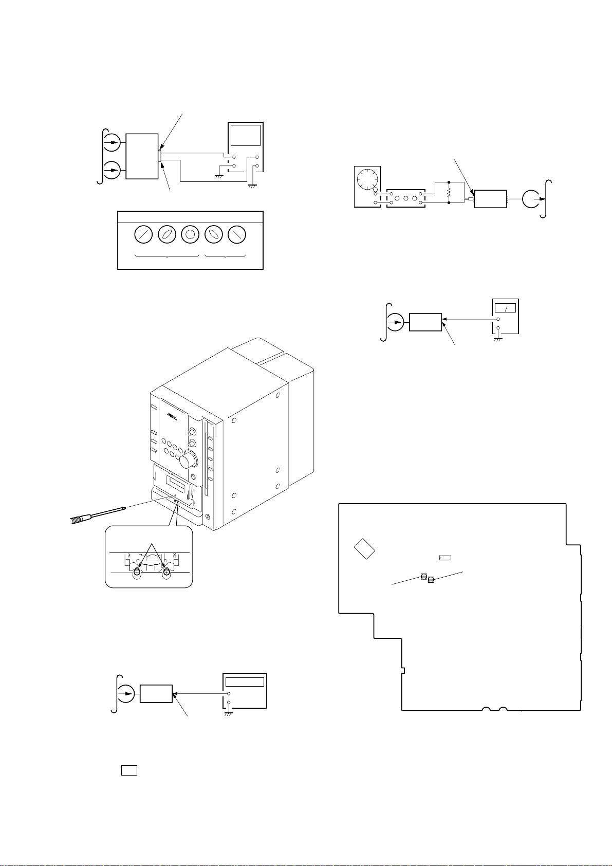
Procedure:
1. Mode: Playback
2. Turn the adjustment screw and check output peaks. If the peaks
do not match for L-CH and R-CH, turn the adjustment screw
so that outputs match within 1dB of peak.
22
L-CH
peak
Screw
position
R-CH
peak
Output
level
within
1dB
L-CH
peak
R-CH
peak
within
1dB
Screw
position
CX-LMN5
+
–
set
recorded
portion
MAIN board speaker terminal (J201)
level meter
attenuator
set
MAIN board
AUX IN (J602)
1) 315 Hz
2) 10 kHz
50 mV (–23.8 dB)
600
Ω
blank tape
CN-123
AF OSC
SFR452
Record Bias
Adjustment(R-CH)
SFR451
Record Bias
Adjustment(L-CH)
IC601
IC901
3. Mode: Playback
MAIN board
test tape
P-4-A100
(10 kHz, – 10 dB)
L-CH
set
R-CH
in phase 45°90°135°180
SPEAKER terminal (J201)
L-CH
R-CH
waveform of oscilloscope
good
oscilloscope
wrong
H
V
°
4. After the adjustments, apply suitable locking compound to the
parts adjusted.
Adjustment Location: Record/Playback/Erase Head
Record Bias Adjustment
Procedure:
1. Record mode
2. Mode: Playback
i-Bass OFF
BASS 0
TREBLE 0
adjustment screw
Note: Refer to “3-6. Cassette Panel” (see page 9)
Tape Speed Check
Mode: Playback
test tape
WS-48B
(3 kHz, 0 dB)
3. Confirm playback the signal recorded in step 1 become
adjustment level as follows.
4. If these levels do not adjustment level, adjustment the SFR451
(L-CH) and SFR452 (R-CH) to repeat steps 1 and 4.
Adjustment level: Playback output of 315 Hz to playback output
of 10 kHz: 0 ± 1.0 dB (0 ± 4.5mV).
Adjustment Location: MAIN board
[MAIN BOARD] – Component Side –
frequency counter
1. Insert the WS-48B into the deck.
2. Press the N button on the deck.
3. Confirm that the frequency counter reads 3,000 ± 90 Hz.
Sample value of Wow and Flutter: 0.3% or less W.RMS (JIS)
set
MAIN board
SPEAKER terminal (J201)
L-CH, R-CH
(WS-48B)
+
–
23
 Loading...