

Sony CXA2500N, CXA2500M Datasheet
Dual REC/PB Preamplifier
Description
The CXA2500M/N is a dual recording/playback preamplifier system bipolar IC which has been developed
for the low voltage operating cassette tape recorder.
Features
• Low quiescent current (VCC = 2V)
PB: ICC = 3.2mA (typ.)
REC: ICC = 5.2mA (typ.)
• Very few external parts
• Built-in Metal/Normal selection switch
• Small switching noise due to internal transient
muting
Applications
3V headphone radio cassette recorders
Structure
Bipolar silicon monolithic IC
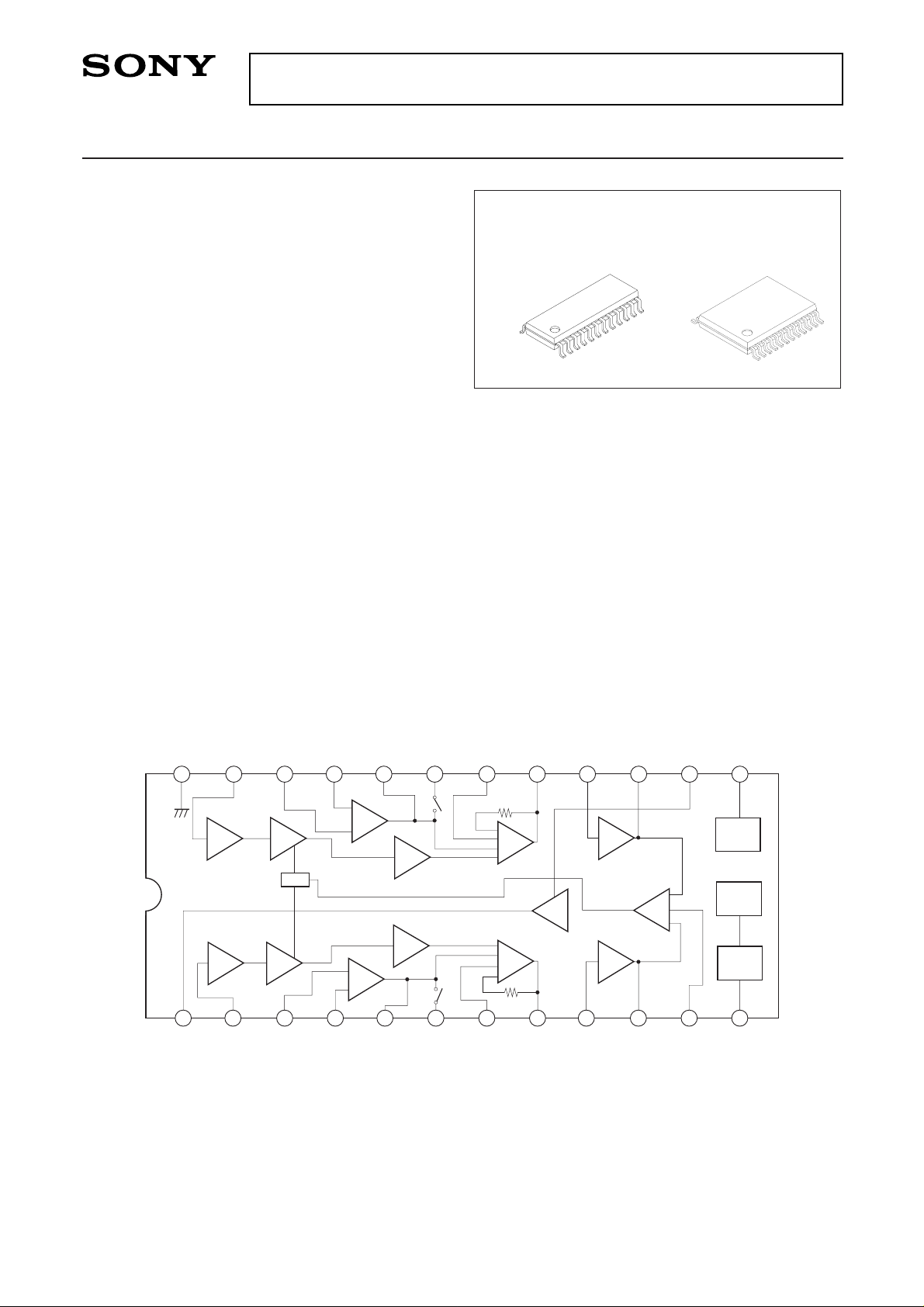
Bock Diagram
Absolute Maximum Ratings (Ta = 25°C)
• Supply voltage VCC 7V
•Operating temperature Topr –20 to +75 °C
• Storage temperature Tstg –65 to +150 °C
• Allowable power dissipation PD
CXA2500M 600 mW
CXA2500N 470 mW
Operating Conditions
Supply voltage PB VCC 1.2 to 3.5 V
REC VCC 1.6 to 3.5 V
– 1 –
E94806B8Y
Sony reserves the right to change products and specifications without prior notice. This information does not convey any license by
any implication or otherwise under any patents or other right. Application circuits shown, if any, are typical examples illustrating the
operation of the devices. Sony cannot assume responsibility for any problems arising out of the use of these circuits.
CXA2500M/N
REFERENCE
MIC INPUT (A)
PB PRE
INPUT (A)
PB NF (A)
PB OUTPUT (A)
PB EQ
SWITCH (A)
TUNER
INPUT (A)
LINE
OUTPUT (A)
REC DRIVE
INPUT (A)
REC DRIVE
OUTPUT (A)
AGC TIME
CONSTANT
TAPE/TUNER
SELECTOR
GROUND
MIC INPUT (B)
PB PRE
INPUT (B)
PB NF (B)
PB OUTPUT (A)
PB EQ
SWITCH (B)
TUNER
INPUT (B)
LINE
OUTPUT (B)
REC DRIVE
INPUT (B)
REC DRIVE
OUTPUT (B)
V
CC
PB/REC
SELECTOR
6dB
22dB
12dB
–0.3dB
20.5dB
MIC
GCA
PB
LINE
REC
AMP
REF
PB/
REC
NORM/
METAL
TAPE/
TUNER
AGC
LINE
AMP
PB
GCA
MIC
REC
AGC
DET
2
3
4
5
6
7
8
9
10
11
12
13
1415
16
17
18
19
20
21
22
23
24
1
CXA2500M
24 pin SOP (Plastic)
CXA2500N
24 pin SSOP (Plastic)
– 2 –
CXA2500M/N
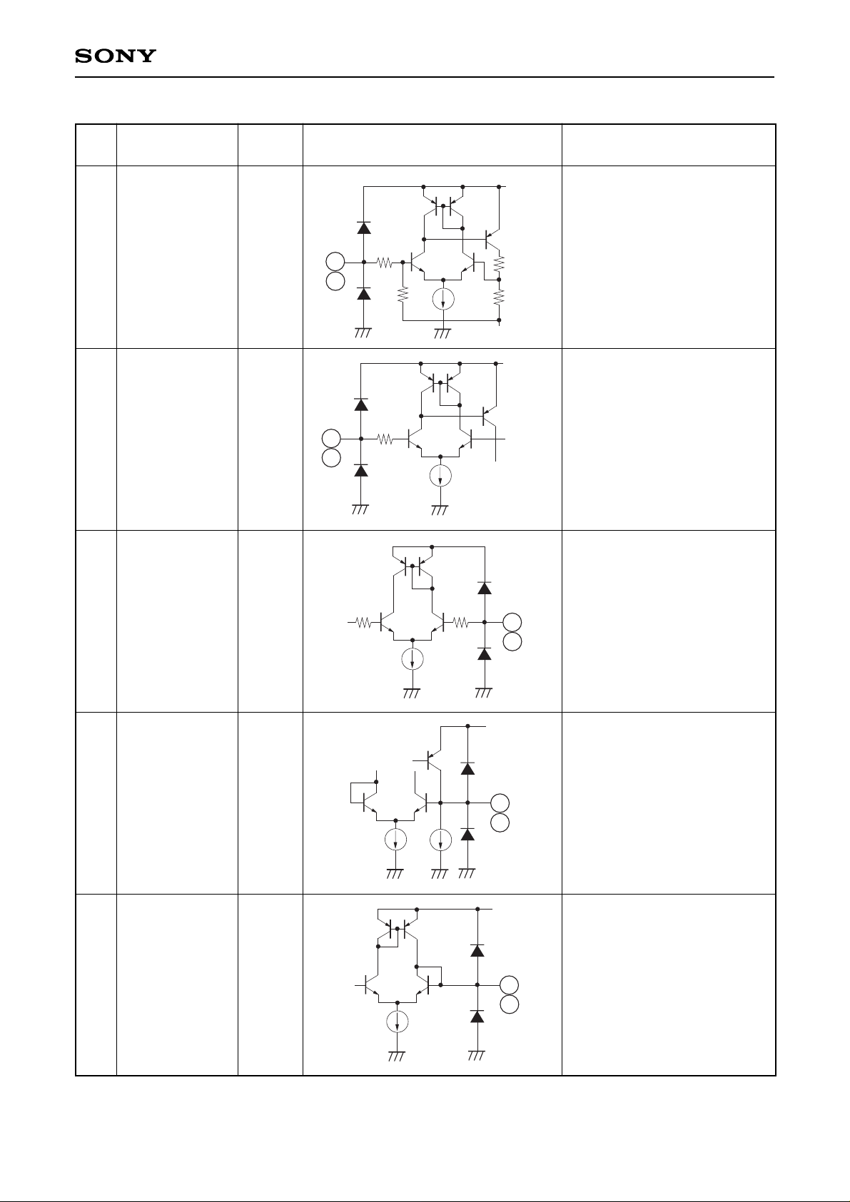
Pin Description Pin voltage is during VCC = 2V
No.
223MIC IN (A)
MIC IN (B)
0.93V MIC preamplifier input
PB preamplifier input
PB equalizer circuit negative
feedback
PB preamplifier output
PB equalizer switch
0.93V
0.93V
0.93V
0.93V
PB PRE IN (A)
PB PRE IN (B)
PB-NF (A)
PB-NF (B)
PB OUT (A)
PB OUT (B)
PB EQ SW (A)
PB EQ SW (B)
3
22
4
21
5
20
6
19
Symbol
Voltage
(Typ.)
Equivalent circuit Description
510
10k
20k
20k
VCC
Vref
2
23
510
VCC
Vref
22
3
510
VCC
Vref
510
4
21
VCC
20
5
VCC
6
19
– 3 –
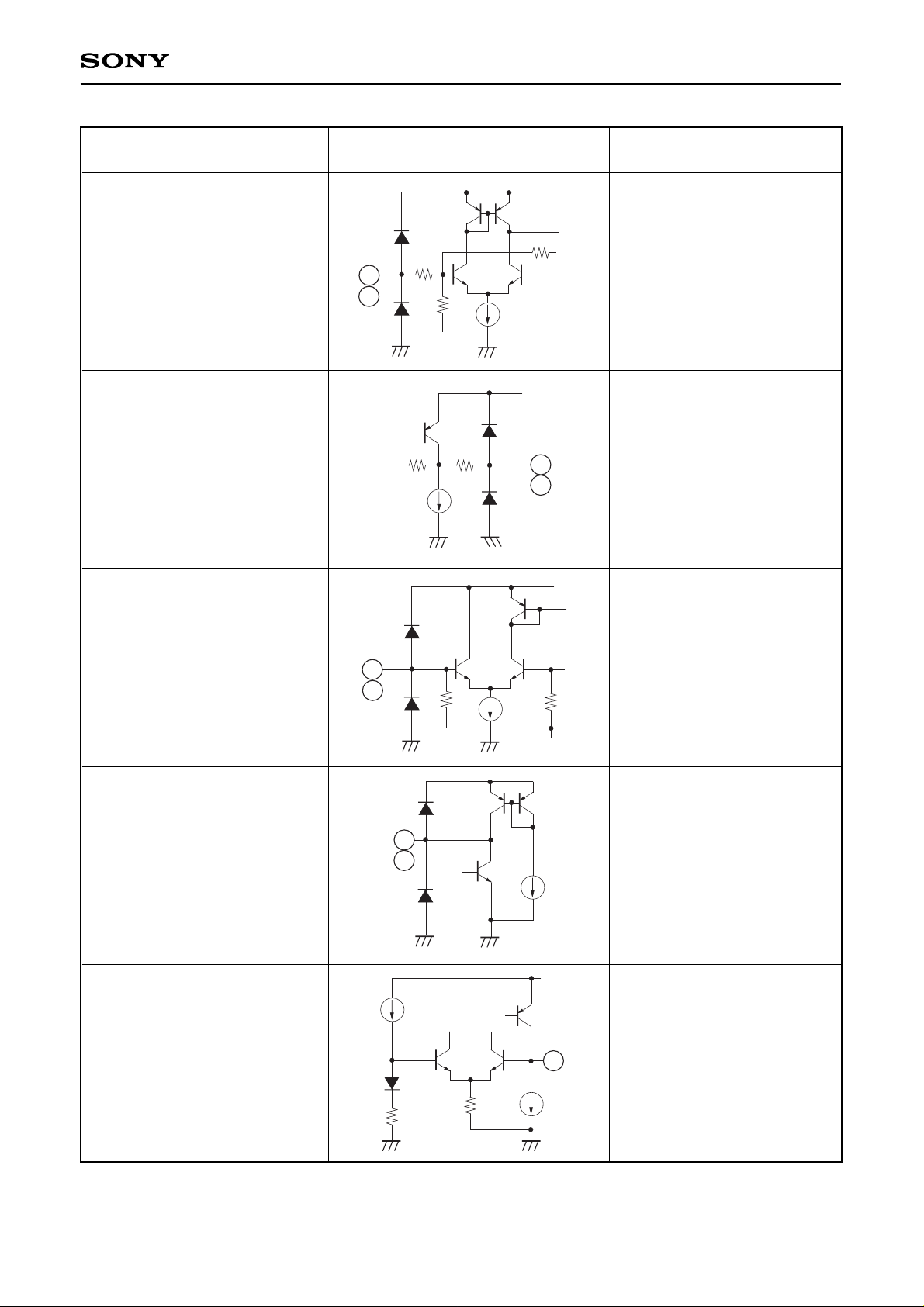
CXA2500M/N
No.
718TUNER IN (A)
TUNER IN (B)
0.93V Tuner input
Line amplifier output
REC drive input
REC drive output
Reference voltage output
0.58V
0.93V
1.0V
0.93V
LINE OUT (A)
LINE OUT (B)
REC AMP IN (A)
REC AMP IN (B)
REC AMP OUT
(A)
REC AMP OUT
(B)
REF
8
17
9
16
10
15
1
Symbol
Voltage
(Typ.)
Equivalent circuit Description
40k
4k
VCC
Vref
40k
18
7
142
40k
VCC
8
17
10k
4k
VCC
Vref
16
9
VCC
10
15
VCC
1
– 4 –
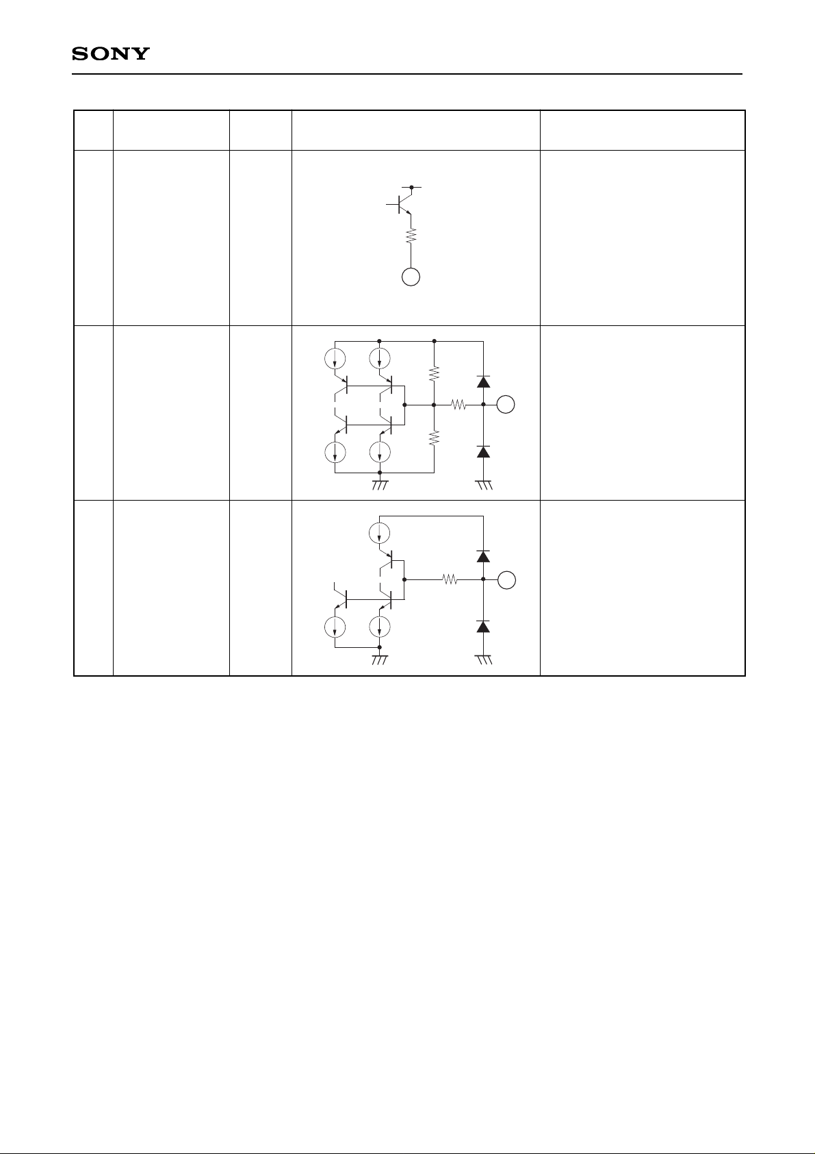
CXA2500M/N
No.
11 AGC TC 0.37V AGC time constant
Tape/tuner selection
During Tape/Normal: 0V
During Tape/Metal: 0.5V
During Tuner Mode: 2.0V
PB/REC selection
During PB = 0V
During REC = 2.0V
0.5V
(Open)
0V
(2.0V)
TAPE/TUNER
PB/REC
12
13
Symbol
Voltage
(Typ.)
Equivalent circuit Description
1k
VCC
11
150k
VCC
142
50k
12
VCC
142
13
 Loading...