

Page 1

CIS-202
Control System Interface
Instruction and Protocol Manual
Release 1.00
Page 2

TABLE OF CONTENTS
Introduction .....................................................................................1
Parts Identification..............................................................................1
Front Panel.............................................................................1
Rear Panel..............................................................................2
CIS-202 RS-232 Protocol
Overview ...............................................................................3
Examples:
Command Number 8
Relay ON ...............................................................................4
Command Number 7
Relay OFF..............................................................................5
Page 3
Introduction
The CIS-202 Control Interface provides four Relay / Contact Closures. The maximum
ratings are:
0.6A 125V AC
0.6A 110V DC
2.0A 30V D C
The CIS-202 can be used either alone or in any combination of CIS-200 series devices, up
to a maximum of 16. Since RS232 is a single-ended data transmission method (between
only one transmitter and one receiver) only one CIS-200 can be used (since it is full two
way), but by utilizing a buffered ‘loop out’ from each unit, up to 15 additional one way
devices (CIS-201 and/or CIS-202) can reside on the the same bus. Each one way device
has its own ID number (1-15), selected by its front panel dip-switch. ID number 0 is
reserved for the CIS-200.
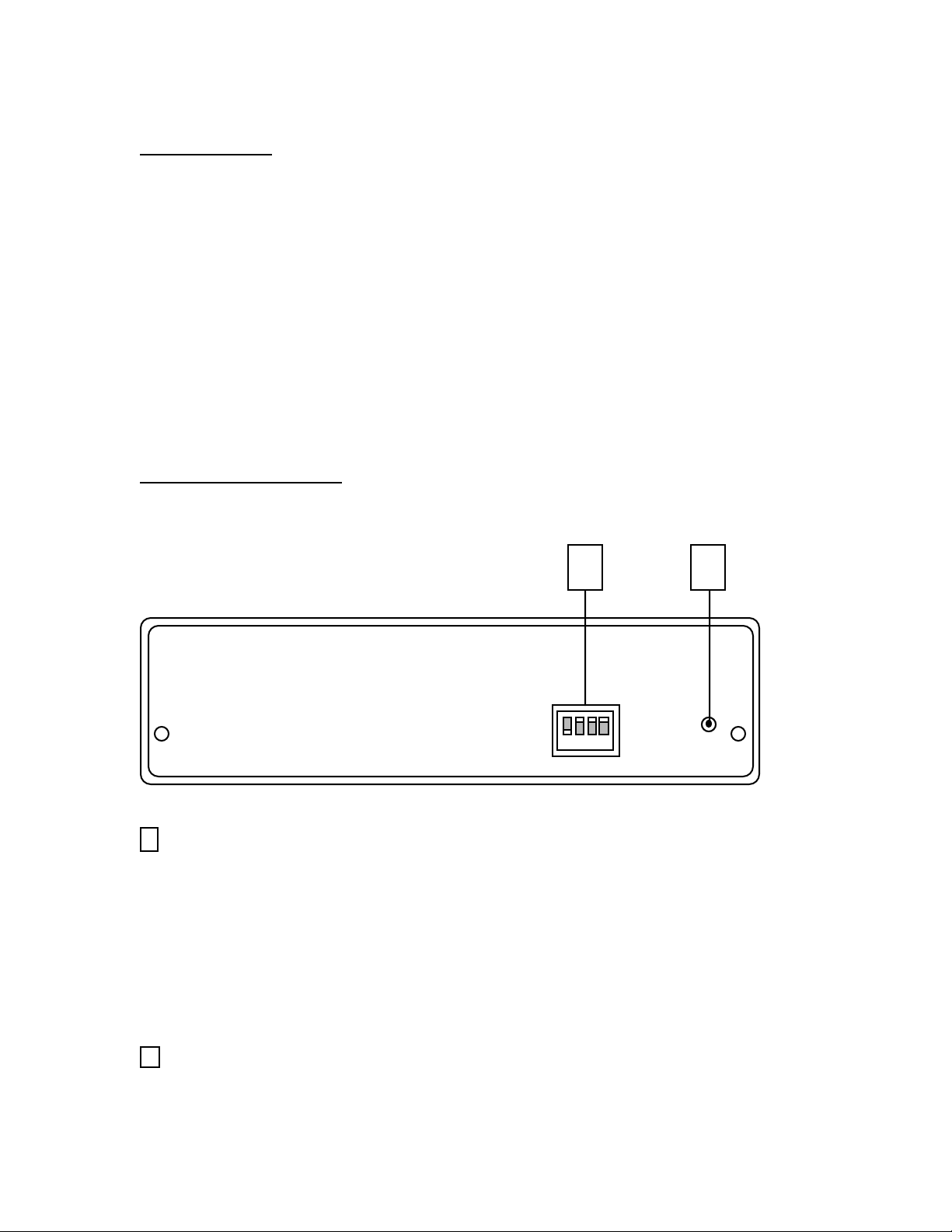
Parts Identification
Front Panel
21
1
ID Select DIP Switch
Selects the ID number for the unit, from 1 to 15. Works as a Binary Switch, i.e.
Switch 1 = 1
Switch 2 = 2
Switch 3 = 4
Switch 4 = 8
Switches add in any combination to equal values from 0 to 15
ID number 0 is reserved for the CIS-200.
2
POWER on LED Indicator
1
Page 4

Rear Panel
1 2 3 4
1
POWER Connector
Input for 9VDC-500mA Power Supply (Supplied)
2
RS232 Connector - (Input)
2 pin Terminal Block Connection to User Interfaces RS232 Control System
Serial Port or Loop Out Connector of other CIS-200 Series Expansion Interface(s).
Typical Wiring Configurations:
CIS- 202 I/O 9-Pin D-Sub
RX < Pin 3 - TX
GND - Pin 5 - GND
CIS- 202 I/O CIS-200 Series Interface
RX < TX
GND - GND
3
RS232 Connector - (Loop Out)
2 pin Terminal Block Connection to Additional CIS-200 Series ExpansionInterface(s).
Typical Wiring Configuration:
RS232 RS232
on CIS- 202 I/O on expansion
TX > RX
GND - GND
4
Relay Connectors
Four Terminal Block Header connectors. Typical Wiring Configuration, Left to Right:
Pin 1 Normally Closed
Pin 2 Common
Pin 3 Normally Open
2
Page 5

CIS-202 RS-232 Protocol
Overview
Transfer Format
Transfer Rate 9600bps
Character Length 8 bits
Parity Check None
Start Bit 1
Stop Bit 1
ID Number
CIS-202 ID Number = Selectable 1 through 15
(ID number 0 is reserved for the CIS-200).
Relay Number
Relay Number Assignments:
Relay 1 = 01H
Relay 2 = 02H
Relay 3 = 04H
Relay 4 = 08H
Note: Multiple relays may be sent by ‘OR-ing’ relay numbers,.i.e,
00H = N/A 04H = Relay 3 08H = Relay 4 0CH = Relay’s 3,4
01H = Relay 1 05H = Relay’s 1,3 09H = Relay’s 1,4 0DH = Relay’s 1,3,4
02H = Relay 2 06H = Relay’s 2,3 0AH = Relay’s 2,4 0EH = Relay’s 2,3,4
03H = Relay’s 1,2 07H = Relay’s 1,2,3 0BH = Relay’s 1,2,4 0FH = All Relays
CIS-202 Protocol Summary
Send Strings (x = ID Number)
Command Terminating
Header No. byte
Relay ON <8xH> <8> <Relay #> <FxH>
Relay OFF <8xH> <9> <Relay #> <FxH>
3
Page 6

Command Number 8
Relay ON
st
1
Byte 2
Attention
Byte
nd
Byte 3
Command
Number
rd
Byte 4
Relay
Number
th
Byte
Terminating
Byte
1st Byte: Attention Byte
<8xH> 80H logically OR’d with ID number.
2nd Byte: Command Number
<8> Relay On
3rd Byte: Relay Number
Relay Number(s) 1 through 4 (see ‘Relay Number’ on page 3 for format)
4th Byte: Terminating Byte
<FxH>F0H logically OR’d with ID number.
Example: Relay ON
CIS-202 ID number 2 - Relays 1 & 4
st
1
Byte 2
nd
Byte
rd
3
Byte 4
08H82H 72H09H
Attention
Byte
Command
Number
Relay
Number(s)
4
th
Byte
Terminating
Byte
Page 7

Command Number 9
Relay OFF
st
1
Byte 2
Attention
Byte
nd
Byte 3
Command
Number
rd
Byte 4
Relay
Number
th
Byte
Terminating
Byte
1st Byte: Attention Byte
<8xH> 80H logically OR’d with ID number.
2nd Byte: Command Number
<9> Relay Off
3rd Byte: Relay Number
Relay Number(s) 1 through 4 (see ‘Relay Number’ on page 3 for format)
4th Byte: Terminating Byte
<FxH>F0H logically OR’d with ID number.
Example: Relay OFF
CIS-202 ID number 2 - Relays 1 & 4
st
1
Byte 2
nd
Byte
rd
3
Byte 4
09H82H 72H09H
Attention
Byte
Command
Number
Relay
Number(s)
5
th
Byte
Terminating
Byte
 Loading...