

Page 1

CIS-201
Control System Interface
Instruction and Protocol Manual
Release 1.00
Page 2

TABLE OF CONTENTS
Introduction .....................................................................................1
Parts Identification..............................................................................1
Front Panel.............................................................................1
Rear Panel..............................................................................2
CIS-201 RS-232 Protocol
Overview ...............................................................................3
Examples:
Command Number 6
Send Control-S Data ..................................................................4
Command Number 7
Send Control-S Data Continuous....................................................5
Stop All Data ....................................................................................6
CIS-201 Protocol Summary...................................................................6
Control-S Product Codes......................................................................6
Control-S Command Codes:
AC3 ...........................................................................................7
AMP ...........................................................................................8
AUDIO SYSTEM / PREAMP ................................................................9
AUDIO TUNER..............................................................................10
CD1, CD2, CD3.............................................................................. 11
DAT .........................................................................................12
DSS .........................................................................................13
DST .........................................................................................14
DVD ......................................................................................... 15
LDP .........................................................................................16
MD .........................................................................................17
CRT PROJECTOR........................................................................... 18
LCD PROJECTOR...........................................................................19
SOUND ADAPTOR .........................................................................20
TAPE .........................................................................................22
TV .........................................................................................23
VCR1, VCR2, VCR3........................................................................24
Page 3
Introduction
The CIS-201 Control Interface is designed to allow both hardwired and infrared control of
Sony audio/video products from an RS232C serial communications device. It provides
four discrete control channels, each with parallel outputs of Control-S and Infrared.
Therefore any command sent via channel 1 will be output by both Control-S and Infrared
outputs 1. If different category products are connected in this way, i.e. a TV to Control-S
1 and a DVD to Infrared 1, that channel can be shared, as each product will only respond to
commands with its own product code.
The CIS-201 can be used either alone or in any combination of CIS-200 series devices, up
to a maximum of 16. Since RS232 is a single-ended data transmission method (between
only one transmitter and one receiver) only one CIS-200 can be used (since it is full two
way), but by utilizing a buffered ‘loop out’ from each unit, up to 15 additional one way
devices (CIS-201 and/or CIS-202) can reside on the the same bus. Each one way device
has its own ID number (1-15), selected by its front panel dip-switch. ID number 0 is
reserved for the CIS-200.
Parts Identification
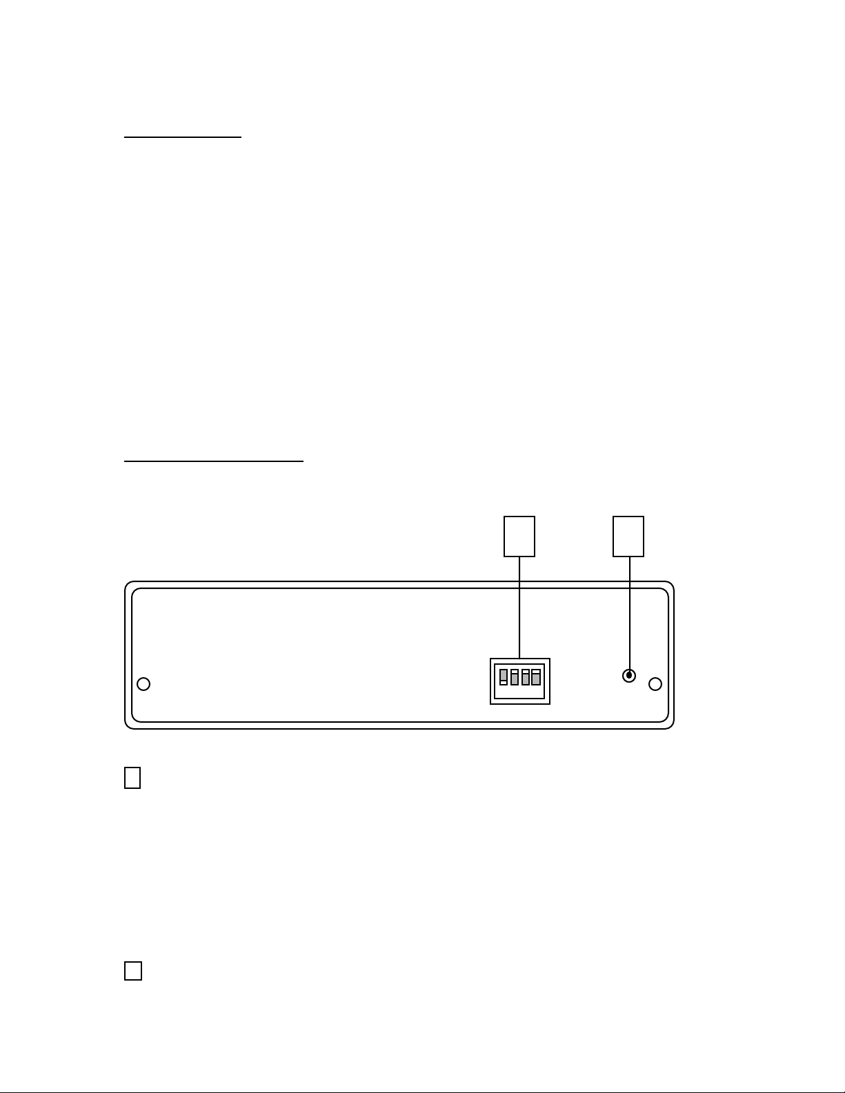
Front Panel
1
ID Select DIP Switch
Selects the ID number for the unit, from 1 to 15. Works as a Binary Switch, i.e.
Switch 1 = 1
Switch 2 = 2
Switch 3 = 4
Switch 4 = 8
Switches add in any combination to equal values from 0 to 15
ID number 0 is reserved for the CIS-200.
21
2
POWER on LED Indicator
1
Page 4
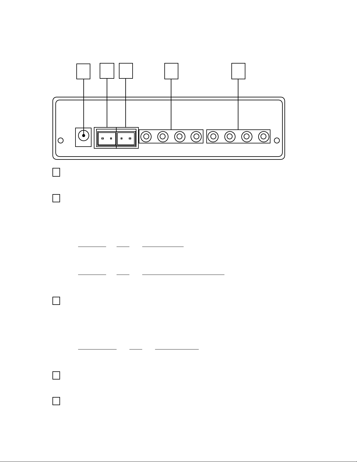
Rear Panel
1 2 3 4 5
1
POWER Connector
Input for 9VDC-500mA Power Supply (Supplied)
2
RS232 Connector - (Input)
2 pin Terminal Block Connection to User Interfaces RS232 Control System
Serial Port or Loop Out Connector of other CIS-200 Series Expansion Interface(s).
Typical Wiring Configurations:
CIS-201 I/O 9-Pin D-Sub
RX < Pin 3 - TX
GND - Pin 5 - GND
CIS-201 I/O CIS-200 Series Interface
RX < TX
GND - GND
3
RS232 Connector - (Loop Out)
2 pin Terminal Block Connection to Additional CIS-200 Series ExpansionInterface(s).
Typical Wiring Configuration:
RS232 RS232
on CIS-201 I/O on expansion
TX > RX
GND - GND
4
CONTROL-S Connectors
Four 1/8” (3.5mm) mono mini phone jacks.
5
INFRARED Connectors
Four 1/8” (3.5mm) mono mini phone jacks. Accepts standard infrared emitters.
2
Page 5

CIS-201 RS-232 Protocol
Overview
Transfer Format
Transfer Rate 9600bps
Character Length 8 bits
Parity Check None
Start Bit 1
Stop Bit 1
ID Number
CIS-201 ID Number = Selectable 1 through 15
(ID number 0 is reserved for the CIS-200).
Channel Number
Control-S / Infrared Channel Assignments:
Channel 1 = 01H
Channel 2 = 02H
Channel 3 = 04H
Channel 4 = 08H
Note: Multiple channels may be sent by ‘OR-ing’ channel numbers,.i.e,
00H = N/A 04H = Ch 3 08H = Ch 4 0CH = Ch’s 3,4
01H = Ch 1 05 H = Ch’s 1,3 09H = Ch’s 1,4 0DH = Ch’s 1,3,4
02H = Ch 2 06 H = Ch’s 2,3 0AH = Ch’s 2,4 0EH = Ch’s 2,3,4
03H = Ch’s 1,2 07H = Ch’s 1,2,3 0BH = Ch’s 1,2,4 0FH = All Channels
Send Strings:
Control-S Send Strings
Send Control-S Data
Send Control-S Data Continuous
Stop ALL Data
3
Page 6
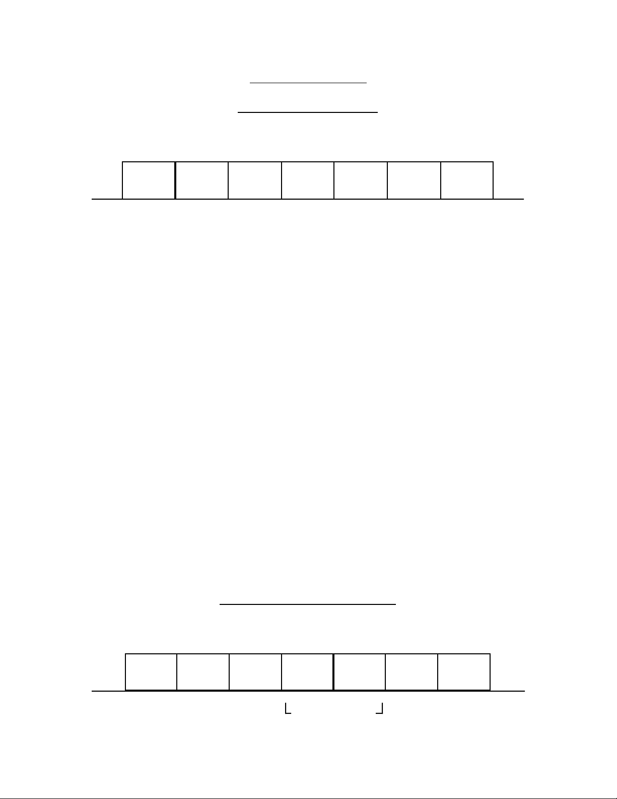
Command Number 6
Send Control-S Data
st
1
Byte 2
Attention
Byte
nd
Byte 3
Command
Number
rd
Byte 4
Channel
th
Byte
Product
code - HI
th
5
Byte
Product
code - LO
th
6
Byte
Command
1st Byte: Attention Byte
<8xH> 80H logically OR’d with ID number.
2nd Byte: Command Number
<6> Send Control-S Data
3rd Byte: Channel
Control-S channel(s) 1 through 4 (see ‘Channel Number’ on page 3 for format)
4th Byte: Product Code HI Byte
5th Byte: Product Code LO Byte
th
7
Byte
Terminating
Byte
6th Byte: Command
7th Byte: Terminating Byte
<FxH>F0H logically OR’d with ID number.
Example: <VCR3> <PLAY>
CIS-201 ID number 5 - Channels 1, 2 & 3
st
Byte
1
nd
2
Byte 3
rd
Byte 4
06H85H 00H07H 14H
Attention
Byte
Command
Number
Channel
Number
th
Byte
Product code: VCR3
th
5
Byte
LO ByteHI Byte
th
6
Byte
24H
Command:
PLAY
th
7
Byte
F5H
Terminating
Byte
4
Page 7
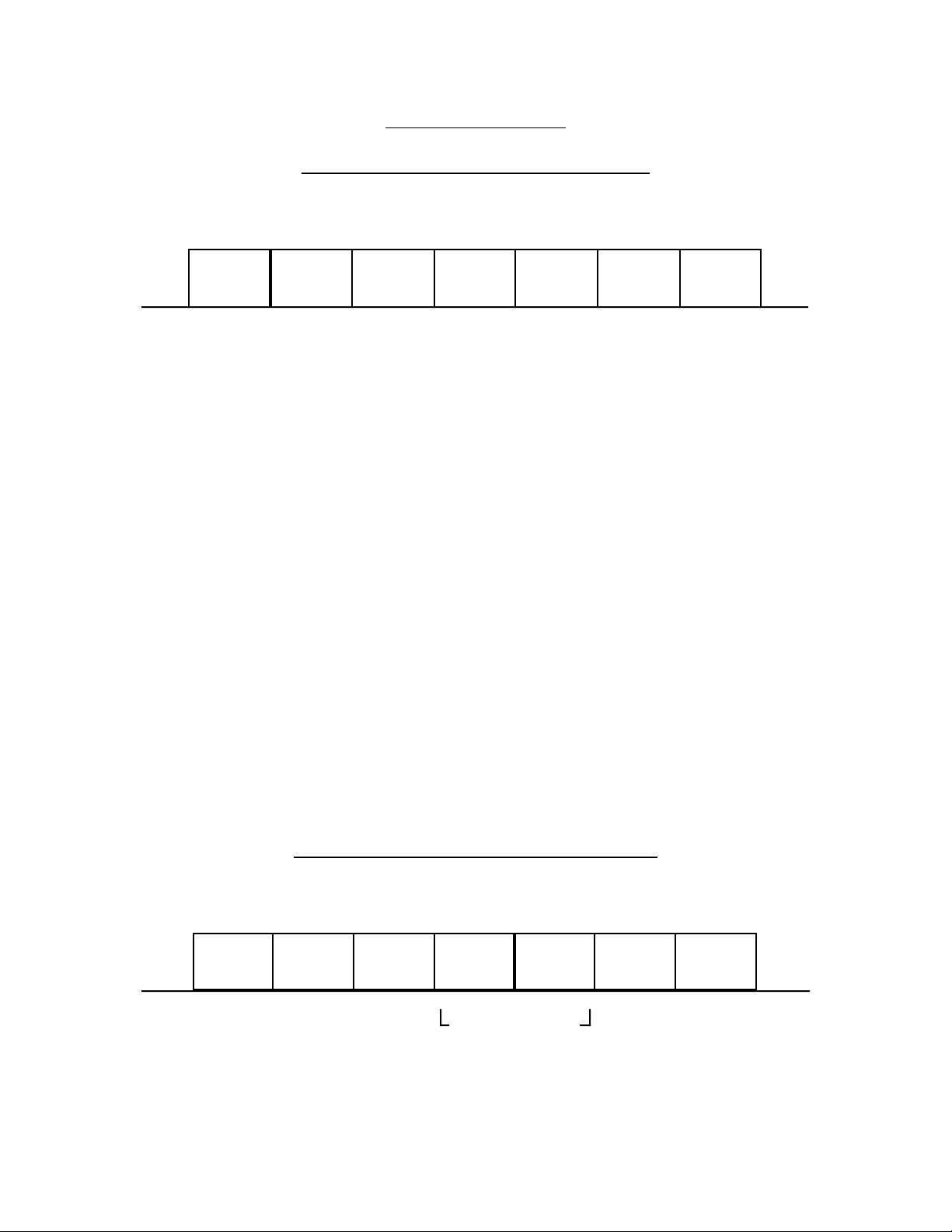
Command Number 7
Send Control-S Data Continuous
st
1
Byte 2
Attention
Byte
nd
Byte 3
Command
Number
rd
Byte 4
Channel
th
Byte
Product
code - HI
th
5
Byte
Product
code - LO
th
6
Byte
Command
1st Byte: Attention Byte
<8xH> 80H logically OR’d with ID number (80H for CIS-200).
2nd Byte: Command Number
<7> Send Control-S Data Continuous
3rd Byte: Channel
Control-S channel(s) 1 through 4 (see ‘Channel Number’ on page 3 for format)
4th Byte: Product Code HI Byte
5th Byte: Product Code LO Byte
th
7
Byte
Terminating
Byte
6th Byte: Command
7th Byte: Terminating Byte
<FxH>F0H logically OR’d with ID number.
Example: <TV> <CHANNEL UP (+)>
CIS-201 ID number 2 - Channel 3
st
Byte
1
nd
2
Byte 3
rd
Byte 4
07H82H 00H04H 10H
Attention
Byte
Command
Number
Channel
Number
th
Byte
Product code: TV
th
5
LO ByteHI Byte
Byte
th
6
Byte
15H
Command
CH UP (+)
th
7
Byte
F2H
Terminating
Byte
5
Page 8

Stop All Data
This command stops all Control-S Continuous data being sent. This must be sent after any
continuous command has been initiated, otherwise the next command(s) sent will be
ignored.
1 Byte: Attention Byte
<9xH> 90H logically OR’d with ID number.
CIS-201 Protocol Summary
Send Strings (x = ID Number)
Command Terminating
Header No. Product Code Command byte
Send Control-S Data <8xH> <3> <Chnl> <Hi> <Lo> <Data> <FxH>
Send Control-S Continuous <8xH> <4> <Chnl> <Hi> <Lo> <Data> <FxH>
Stop ALL Data <9xH>
CONTROL-S PRODUCT CODES
HI byte LO byte PRODUCT
00 10 TV
00 12 VCR 1
00 13 VCR 2
00 14 VCR 3
00 17 LDP
00 1A PROJECTOR
00 40 AMP
00 41 AUDIO TUNER
00 42 AUDIO SYS / PREAMP
00 43 SOUND ADAPTOR
00 44 CD 1
00 45 CD 2
00 46 CD 3
00 47 MD
00 48 TAPE
00 49 D AT
00 60 DS T
00 61 DSS
01 2B DVD
02 2B AC3 PROCESSOR
The following pages contain every available code for each product category. Since
features vary from model to model, not every command will work with every product.
6
Page 9

HI - LO
Category: AC3 Control-S Product Code : 02 - 2B
6th byte CODE NAME
0B INPUT SELECT - NEXT
0C INPUT SELECT - PREV
0D MENU SELECT
13 MASTER VOL - UP
14 MASTER VOL - DOWN
1D REAR BALANCE - R
1E REAR BALANCE - L
21 MUTE ON / OFF
30 EFFECT +
31 EFFECT 3E OFF
43 DOLBY SURROUND
44 MODE
48 BYPASS
49 CENTER +
4A CENTER 4B SUB WOOFER +
4C SUB WOOFER 4E TEST
4F DISPLAY
50 FRONT BALANCR - L
51 FRONT BALANCR - R
52 REAR +
53 REAR -
72 MENU SELECT +
73 MENU SELECT -
74 MENU SELECT DOWN
75 MENU SELECT UP
7
Page 10

HI - LO
Category: AMP Control-S Product Code : 00 - 40
6th byte CODE NAME 6th byte CODE NAME
0 POWER ON / OFF 36 SURROUND
1 1 38 REC OUT OFF
2 2 39 DDS
3 3 3A TREBLE +
4 4 3B TREBLE 5 5 3C BASS +
6 6 3D BASS 7 7 3E SURROUND 1 (OFF)
8 8 3F SURROUND 2 (DOLBY)
9 9 40 SURROUND 3 (HALL)
0A 0 / 10 41 SURROUND 4 (SIMUL)
0D ENTER 42 SURROUND 5
0F MEMORY 44 SURROUND MODE
10 CLEAR 45 SURROUND ON / OFF
11 POWER ON 46 LOUDNESS
12 POWER OFF 47 BASS BOOST / DBFB
13 VOL - UP 48 DEFEAT
14 VOL - DOWN 49 REC OUT LDP
15 EQ + 4A REC OUT VIDEO 1
16 EQ - 4B REC OUT VIDEO 2
17 PHONO 4C REC OUT VIDEO 3
18 TUNER 4D REC OUT PHONO
19 VIDEO 1 4E REC OUT TUNER
1A TAPE 1 4F REC OUT CD
1B TAPE 2 50 REC OUT TAPE 1
1C CD 51 REC OUT TAPE 2
1D BAL - LEFT 52 REC OUT TAPE 3
1E BAL - RIGHT 53 REC OUT AUX 1
1F EFFECT ON / OFF 54 REC OUT AUX 2
20 EQ ON 55 REC OUT AUX 3
21 MUTE 56 REC OUT AUX 4
22 DIGITAL - 2 57 REC OUT TV
23 DIGITAL - 1 58 REAR SPKR ON / OFF
24 VIDEO 3 5A PRESET MODE SEL.
25 TAPE 3 / DAT 5C HIGH - FILTER
26 AUX 1 5D LO - FILTER
27 AUX 2 5E SUB WOOFER ON/OFF
28 TV 5F SPEAKER A
29 LDP 60 SPEAKER B
2A VIDEO 2 61 SPEAKER A+B
2B EQ ON / OFF 6E VIDEO FUNCTION +
2C EQ OFF 6F VIDEO FUNCTION 2D MEMORY 1 70 EFFECT LEVEL
2E MEMORY 2 71 REAR LEVEL
2F MEMORY 3 72 CURSOR UP
30 SURR. BAL - FRONT 73 CURSOR DOWN
31 SURR. BAL - REAR 74 CURSOR LEFT
32 SURR. EFFECT + 75 CURSOR RIGHT
33 SURR. EFFECT - 7B FUNCTION +
34 SURR. DELAY + 7C FUNCTION -
35 SURR. DELAY -
8
Page 11

HI - LO
Category: AUDIO SYSTEM / PREAMP Control-S Product Code : 00 - 42
6th byte CODE NAME 6th byte CODE NAME
0 POWER ON / OFF 31 VIDEO 5
1 1 32 VIDEO 3
2 2 33 VIDEO 4
3 3 34 DIGITAL 1
4 4 35 DIGITAL 2
5 5 36 DAT
6 6 38 CD SYNCRO
7 7 39 REWIND
8 8 3A FF & FWD
9 9 3B REC FWD
0A 10 / ( 0 ) 3C REC STANDBY
0B 11 3D REVERSE
0C 12 3E STOP
0D ENTER 3F PAUSE
0E SIMUL 40 REC REVERSE
0F MEMORY 41 REW & REVERSE
10 TUNER BAND CYCLIC 42 FF & REVERSE
11 POWER ON 43 PLAY
12 POWER OFF 44 TC PROGRAM
13 VOL UP 45 REC MUTE
14 VOL DOWN 46 REW & FWD
15 CH UP / TUNE UP 47 FF & FWD
16 CH DOWN / TUNE DOWN 48 FWD
17 PHONO 4D SOURCE DIRECT
18 TUNER 4E MAIN
19 VIDEO 1 4F DISPLAY
1A TAPE 1 51 DIMMER ON / OFF
1B TAPE 2 52 DIMMER ON (DARK)
1C CD 53 DIMMER OFF (BRIGHT)
1D BAL LEFT 54 REC OUT SET ON/OFF
1E BAL RIGHT 55 REC OUT SET ON
1F START 56 REC OUT SET OFF
20 STOP 57 ON SCREEN ON/OFF
21 MUTE 58 SLEEP
22 MEMORY SCAN 59 WAKE UP
23 MPX MAIN / SUB 5A TIMER ON / OFF
24 MW (AM) 7A CD 2
25 SW 1
26 SW 2
27 AUX 1
28 FM
29 LW
2A VIDEO 2
2B EQ ON / OFF
2C SKIP
2D ( MIX )
2E CUE
2F 33 / 45
30 DIGITAL SELECTOR
9
Page 12

HI - LO
Category: AUDIO TUNER Control-S Product Code : 00 - 41
6th byte CODE NAME 6th byte CODE NAME
0 POWER ON / OFF 46 SHIFT A
1 1 47 SHIFT B
2 2 48 SHIFT C
3 3 4C EQ LINK ON / OFF
4 4 4F DISPLAY
5 5 50 CH TEXT
6 6 51 TV SCAN ON
7 7 52 TV SCAN OFF
8 8 53 TV SCAN ON / OFF
9 9 54 INDEX TUNING +
0A 10 / ( 0 ) 55 INDEX TUNING 0B 11 56 INDEX SELECT
0C 12
0D ENTER
0E SIMUL
0F MEMORY
10 BAND CYCLIC
11 POWER ON
12 POWER OFF
13 TUNE - UP
14 TUNE - DOWN
15 CH - UP
16 CH - DOWN
17 MAIN / SUB
18 STEREO / MONO
1D ( + 10 )
1E ( MIX )
22 MEMORY SCAN
23 AUTO / MANUAL
24 MW (AM)
25 SW 1
26 SW 2
27 TV 1 (LOW/TV CYCLIC)
28 FM
29 LW
2A TV 2 (HIGH)
2B TV 3 (UHF)
34 LINE OUT LEVEL +
35 LINE OUT LEVEL -
39 SHIFT A / B / C
3A SCAN MODE
3E 13
3F 14
40 15
41 16
42 17
43 18
44 19
45 20
10
Page 13

HI - LO
Category: CD1, CD2, CD3 Control-S Product Code : 00 - 44,45,45
6th byte CODE NAME 6th byte CODE NAME
0 POWER ON / OFF 31 DISC 2
1 1 32 DISC 3
2 2 33 DISC 4
3 3 34 DISC 5
4 4 35 DISC 6
5 5 36 DISC 7
6 6 37 DISC 8
7 7 38 DISC 9
8 8 39 SCAN REVERSE
9 9 3A SCAN FORWARD
0A 0 3B SHUFFLE PLAY
0B PROGRAM 3C PREVIOUS INDEX
0C ENTER 3D NEXT INDEX
0D PROGRAM START 3E STOP
0E PROGRAM CHECK 3F PAUSE
0F PROGRAM CLEAR 40 SCAN REV. (SLOW)
10 CLEAR 41 SCAN FWD. (SLOW)
11 POWER ON 42 MUSIC SCAN
12 POWER OFF 43 PREVIOUS DISC
13 VOL - UP 44 NEXT DISC
14 VOL - DOWN 46 PREVIOUS TRACK
15 17 47 NEXT TRACK
16 18 48 PLAY
17 10 49 DSP LEVEL +
18 11 4A DSP LEVEL -
19 12 4B DISPLAY ON / OFF
1A 13 4D DISC 10
1B 14 53 PEAK LEVEL SEARCH
1C 15 54 L / R / STEREO
1D 16 57 ANT - SW
1E (+10 / OVER) 5C DSP 1
1F TIME 5D DSP 2
20 20 5E DSP 3
21 MUTE 5F DSP 4
22 OPEN CLOSE 60 DSP 5
23 19 61 DSP MODE
24 FILE RECALL 62 DSP OFF
25 FILE ERASE 63 FADER
26 START (SEARCH) 65 PLAYER SELECT
27 CONTINUOUS MODE 7A LEVEL FILE
28 CUSTOM INDEX 7B DISC MEMO INPUT MODE
29 FILE 7C EDIT / TIME FADE
2A SINGLE MODE
2B PROGRAM MODE
2C REPEAT A-B
2D A-B CLEAR
2E REPEAT 1 DISC
2F REPEAT ( 1 )
30 DISC 1
11
Page 14

HI - LO
Category: DAT Control-S Product Code : 00 - 49
6th byte CODE NAME 6th byte CODE NAME
0 POWER ON / OFF 5D END ID ERASE
1 1 5F AUTO SKIP
2 2 60 TOC
3 3 63 FADER
4 4 64 MODE 1
5 5 65 MODE 2
6 6 66 MODE 3
7 7 67 MODE 4
8 8 68 MODE 5
9 9 69 MODE 6
11 POWER ON 6A MODE 7
12 POWER OFF 6B MODE 8
13 VOL - UP 6C MODE 9
14 VOL - DOWN 6D MODE 0
17 OPEN / CLOSE 76 SCAN MODE
18 COUNTER MODE 7A PREVIOUS PROGRAM
19 CONTER CLEAR 7B NEXT PROGRAM
1A COUNTER MEMORY 7D TIME SEARCH
1C PROGRAM TIME
1D ABSOLUTE TIME
1E LINEAR COUNTER
1F REMAINING TIME
20 CLOCK
25 ENTER
26 PROGRAM START
27 PROGRAM CHECK
2C RECORDED TIME
3C REPEAT
3D REPEAT A-B
3E STOP
3F PAUSE
40 PLAY
41 REW
42 FF
43 REC
44 REC PLAY
45 REC MUTE
49 SKIP ID WRITE
4A SKIP ID ERASE
4B TEST DISPLAY
4C REW PLAY
4F DISPLAY
51 DATE
52 MARGIN RESET
54 START ID AUTO WRITE
55 START ID WRITE
56 START ID ERASE
57 RENUMBER
5C END ID WRITE
12
Page 15

HI - LO
Category: DSS Control-S Product Code : 00 - 61
6th byte CODE NAME
0 POWER ON / OFF
11
22
33
44
55
66
77
88
99
0A 0
0C ENTER
11 POWER ON
12 POWER OFF
15 CH - UP (+)
16 CH - DOWN (-)
3E MENU
40 DISPLAY
5B EXIT
64 GUIDE
65 FAVORITE
68 CURSOR UP
69 CURSOR DOWN
6A CURSOR RIGHT
6B CURSOR LEFT
6C *
76 JUMP
7B TV / DSS
13
Page 16

HI - LO
Category: DST Control-S Product Code : 00 - 60
6th byte CODE NAME
12 POWER OFF
13 VOL - UP
14 VOL - DOWN
18 TUNER
19 VIDEO 1
1A TAPE 1
1B TAPE 2
1C CD 1
21 MUTE ON / OFF
27 TV / AUX
2A VIDEO 2
65 PRIORITY
7A CD 2
14
Page 17

HI - LO
Category: DVD Control-S Product Code : 01 - 2B
6th byte CODE NAME
0 POWER ON / OFF
11
22
33
44
55
66
77
88
99
0A 0
0C ENTER
0F RETURN
10 CLEAR
11 POWER ON
12 POWER OFF
1F TIME
22 OPEN / CLOSE
24 TITLE
25 DVD MENU
30 DISC 1
31 DISC 2
32 DISC 3
33 DISC 4
34 DISC 5
38 DNR
39 SCAN REVERSE
3A SCAN FORWARD
3C X2 REVERSE
3D X2 FORWARD
3E STOP
3F PAUSE
40 STEP REVERSE
41 STEP FORWARD
46 PREV TRACK
47 NEXT TRACK
48 PLAY
49 DISPLAY
4F SEARCH MODE
57 MENU
58 SLOW REVERSE
59 SLOW FORWARD
5A SUB TITLE ON / OFF
5B SUB TITLE CHANGE
70 AUDIO CHANGE
71 ANGLE CHANGE
73 CURSOR UP
74 CURSOR DOWN
75 CURSOR LEFT
78 CURSOR RIGHT
15
Page 18

HI - LO
0 POWER ON / OFF 39 X1
1 1 3A FWD - ACS
2 2 3B REV - ACS
3 3 3C REPEAT START
4 4 3D REPEAT END
5 5 3E REPEAT A - B
6 6 3F ( + 10 )
7 7 40 DISPLAY ON / OFF
8 8 41 ESCAPE
9 9 46 PROGRAM
0A 0 47 CHAPTER REPEAT
0B CHAPTER 48 CX ON / OFF
0C enter / search / next 49 REVERSE
0D FRAME / TITLE 4A STEP SLOW -
0E AUDIO L 4B SLOW -
0F AUDIO R 4C LOW SPEED -
10 CLEAR 4D INDEX MODE
11 POWER ON 4E X 10
12 POWER OFF 4F X 1/2
13 VOL - UP 50 X 1/8
14 VOL - DOWN 51 X 1/30
15 NEXT INDEX 52 HI SPEED +
16 PREVIOUS INDEX 53 MID SPEED +
17 STILL 54 LOW SPEED +
18 UP 55 SLOW +
19 DOWN 56 STEP SLOW +
1A FWD - SPEED 57 FORWARD
1B REV - SPEED 58 KEY LEVEL UP
1D FWD - X3 59 KEY LEVEL NORMAL
1E REV - X3 5A KEY LEVEL DOWN
1F REMAIN / ELAPSE 5B SURROUND SELECT
20 REPEAT ON / OFF 5C MID SPEED -
21 X2 / X3 5D HI - SPEED -
22 OPEN / CLOSE 5E INPUT SELECT VIDEO
23 STEREO AUDIO MONITOR 5F INPUT SELECT AUDIO
24 PLAY 60 CHECK
25 R - SEARCH (SCAN) 61 SIDE A
26 F - SEARCH (SCAN) 62 SIDE B
27 MEMORY STOP 63 FADER
28 STOP 64 DIGITAL OFF
29 PAUSE 65 DIGITAL EFFECT +
2A SLOW REV SCAN 66 DIGITAL EFFECT -
2B SLOW FWD SCAN 67 STOP MOTION
2C ANT - SW 68 DIGITAL RECALL
2D FWD - STEP 69 FLASH MOTION
2E REV - STEP 6A CHAPTER CATALOG
30 AUTO DIGITAL / ANALOG 6B MULTI SLOW
31 SHUFFLE 6C ONE SHOT MEMORY
32 OPEN 72 SOLARIZATION
33 CLOSE 76 PICTURE SELECT
34 BACK 7A INTRO SCAN
35 AUTO PROGRAM 7B EXECUTE
36 AUTO PAUSE / SPACE 7C MULTI AUTO
37 SINGLE / CONTINUE 7D MULTI MANUAL
38 INDEX WRITE
Category: LDP Control-S Product Code : 00 - 17
6th byte CODE NAME 6th byte CODE NAME
16
Page 19

HI - LO
Category: MD Control-S Product Code : 00 - 47
6th byte CODE NAME 6th byte CODE NAME
00 POWER ON/OFF 30 11 [ P ]
01 1 [ F ] 31 12 [ Q ]
02 2 [ G ] 32 13 [ R ]
03 3 [ H ] 33 14 [ S ]
04 4 [ I ] 34 15 [ T ]
05 5 [ J ] 35 16 [ U ]
06 6 [ K ] 36 17 [ V ]
07 7 [ L ] 37 18 [ W ]
08 8 [ M ] 38 19 [ X ]
09 9 [ N ] 39 AUTO SPACE [ ( ]
0A 10 [ O ] 3A MUSIC SCAN [ ) ]
0B >25 [ / ] 3C CAPS
10 CLEAR 3D NUMBER
11 POWER ON 42 NAME
12 POWER OFF 4D 20 [ Y ]
17 PREV 4E 21 [ Z ]
18 NEXT 4F 22 [ - ]
1D REPEAT [ ? ] 50 23 [ ]
1E A-B [ ? ] 51 24 [ . ]
1F STOP 52 25 [ ' ]
20 PAUSE
24 [ E ]
25 [ D ]
27 CONTINUE [ A ]
28 DISPLAY
29 SCROLL
2A SHUFFLE [ B ]
2B PROGRAM [ C ]
2C PLAY
2D FR
2E FF
2F RECORD
17
Page 20

HI - LO
Category: CRT PROJECTOR Control-S Product Code : 00 - 1A
6th byte CODE NAME 6th byte CODE NAME
0B SWITCHER 1 42 SECOND SWITCHER 6
0C SWITCHER 2 43 SECOND SWITCHER 7
0D SWITCHER 3 44 SECOND SWITCHER 8
0E SWITCHER 4 47 POSITION +
0F SWITCHER 5 48 POSITION -
10 SWITCHER 6 4B ZONE
11 POWER ON 4D CENTER RED
12 POWER OFF 4F CENTER BLUE
13 VOL - UP 50 SIZE
14 VOL - DOWN 51 LINEARITY
15 SWITCHER 7 52 SKEW
16 SWITCHER 8 53 BOW
17 HUE - PURPLE 54 KEY
18 HUE - GREEN 55 PIN CUSHION
19 SHARPNESS - HIGH 56 WHITE BALANCE GAIN
1A SHARPNESS - LO 57 WHITE BALANCE BIAS
1B PJ MUTE PIC 5C BLANKING
1C STATUS ON 62 MEMORY
1D STATUS OFF 75 RESET
1E SECAM 79 NORMAL
1F CLEAR BLUE 7F TEST
20 PAGE
21 AUDIO MUTING PROJECTOR VIDEO MEMORY Codes
24 COLOR - HIGH 55 1 Prod Code HI: 12 LO: 76
25 COLOR - LO 56 2 Prod Code HI: 12 LO: 76
28 CONTRAST - HIGH 57 3 Prod Code HI: 12 LO: 76
29 CONTRAST - LO 49 4 Prod Code HI: 12 LO: 76
2A BRIGHTNESS - HIGH 4A 5 Prod Code HI: 12 LO: 76
2B BRIGHTNESS - LO 4B 6 Prod Code HI: 12 LO: 76
2C INPUT SELECT VIDEO 4C 7 Prod Code HI: 12 LO: 76
2D INPUT SELECT A 5C 8 Prod Code HI: 12 LO: 76
2E INPUT SELECT B 5D 9 Prod Code HI: 12 LO: 76
31 ADJUST RED 5E 10 Prod Code HI: 12 LO: 76
32 ADJUST GREEN 54 SW NO/OFF/GRP Prod Code HI: 12 LO: 76
33 ADJUST BLUE
34 CUTOFF RED
35 CUTOFF GREEN
36 CUTOFF BLUE
37 RGB SIZE
38 RGB SHIFT
39 CURSOR RIGHT
3A CURSOR LEFT
3B CURSOR UP
3C CURSOR DOWN
3D SECOND SWITCHER 1
3E SECOND SWITCHER 2
3F SECOND SWITCHER 3
40 SECOND SWITCHER 4
41 SECOND SWITCHER 5
18
Page 21

HI - LO
Category: LCD PROJECTOR Control-S Product Code : 00 - 1A
6th byte CODE NAME 6th byte CODE NAME
0B SWITCHER 1 63 INPUT SELECT S VIDEO
0C SWITCHER 2 75 RESET
0D SWITCHER 3 7E PATTERN
0E SWITCHER 4
0F SWITCHER 5
10 SWITCHER 6
11 POWER ON
12 POWER OFF
13 VOL - UP
14 VOL - DOWN
15 SWITCHER 7
16 SWITCHER 8
17 HUE - PURPLE
18 HUE - GREEN
19 SHARPNESS - HIGH
1A SHARPNESS - LO
1C STATUS ON
1D STATUS OFF
20 PAGE
21 AUDIO MUTING
24 COLOR - HIGH
25 COLOR - LO
28 CONTRAST - HIGH
29 CONTRAST - LO
2A BRIGHTNESS - HIGH
2B BRIGHTNESS - LO
2C INPUT SELECT VIDEO1
2D INPUT SELECT VIDEO2
2E INPUT SELECT RGB
31 FOCUS IN
32 FOCUS OUT
33 PICTURE SHIFT RIGHT
34 PICTURE SHIFT DOWN
35 PICTURE SHIFT UP
36 PICTURE SHIFT LEFT
3D SECOND SWITCHER 1
3E SECOND SWITCHER 2
3F SECOND SWITCHER 3
40 SECOND SWITCHER 4
41 SECOND SWITCHER 5
42 SECOND SWITCHER 6
43 SECOND SWITCHER 7
44 SECOND SWITCHER 8
47 SELECT +
48 SELECT 49 ZOOM IN
4A ZOOM OUT
4B AUTO
5D SELECT
19
Page 22

HI - LO
e
Category: SOUND ADAPTOR Control-S Product Code : 00 - 43
6th byte CODE NAME 6th byte CODE NAME
0 POWER ON / OFF 33 AUDIO
1 16 Hz 34 DELAY TIME +
2 31.5 Hz 35 DELAY TIME -
3 63 Hz 36 EQ MEMORY >10
4 125 Hz 37 VIDEO 4
5 250 Hz 38 ABSOLUTE CH-1
6 500 Hz 39 RTA IN LINE / MIC
7 1 KHz 3A DISPLAY EQ / RTA
8 2 KHz 3B EQ MEMORY 8
9 4 KHz 3C EQ MEMORY +
0A 8 KHz 3D EQ MEMORY 0B 16 KHz 3E EQ MEMORY 1
0C 32 KHz 3F EQ MEMORY 2
0E SLOPE 40 EQ MEMORY 3
0F MEMORY 41 EQ MEMORY 4
10 EQ CH 42 EQ MEMORY 5
11 POWER ON 43 EQ MEMORY 6
12 POWER OFF 44 EQ MEMORY 7
13 VOL - UP 45 EQ FLAT
14 VOL - DOWN 46 AUTO EQ START/STOP
15 GE - HIGH 47 EQ REVERSE
16 GE - LOW 48 RTA HOLD
17 PEQ BAND 49 CENTER +
18 EQ MEMORY 11 4A CENTER 19 EQ MEMORY 12 4B CENTER WOOFER +
1A TAPE 1 4C CENTER WOOFER 1B TAPE 2 4D ABSOLUTE CH-2
1C CD 4E TEST
1D EQ MEMORY 13 4F MODE SCAN
1E LINE 50 MASTER +
1F EQ ON 51 MASTER -
20 EQ OFF 52 SURROUND +
22 EQ FREQ + 53 SURROUND 23 EQ FREQ - 54 SURROUND CH-1 +
24 L + R 55 SURROUND CH-1 25 L / R / L + R 56 SURROUND CH-2 +
26 AUX 1 57 SURROUND CH-2 27 EQ MEMORY 9 58 SURROUND 9
28 L 59 SURROUND 10
29 R 5A SURROUND 11
2A EQ MEMORY 10 5B SURROUND 12
2B AUX 2 5C SURROUND 1
2C EQ * * 5D SURROUND 2
2D EQ MEMORY 14 5E SURROUND 3
2E EQ ON / OFF 5F SURROUND 4
2F EQ MEMORY 15 60 SURROUND 5
30 VIDEO 1 61 SURROUND 6
31 VIDEO 2 62 SURROUND 7
32 VIDEO 3 63 SURROUND 8
ontinued next pag
20
Page 23

HI - LO
Category: SOUND ADAPTOR Control-S Product Code : 00 - 43
CONTINUED
6th byte CODE NAME
64 1
65 2
66 3
67 4
68 5
69 6
6A 7
6B 8
6C 9
6D 0
6E BAL - LEFT
6F BAL - RIGHT
70 SURROUND >12
72 LPF Fc +
73 LPF Fc 74 HPF Fc +
75 HPF Fc 76 DELAY PROGRAM
7A SURR. CH-1 DELAY TIME +
7B SURR. CH-1 DELAY TIME 7C SURR. CH-2 DELAY TIME +
7D SURR. CH-2 DELAY TIME 7E TEST
21
Page 24

HI - LO
Category: TAPE Control-S Product Code : 00 - 48
6th byte CODE NAME 6th byte CODE NAME
0 POWER ON / OFF 44 NEXT TAPE
1 1 46 REW AMS
2 2 47 FF AMS
3 3 48 PLAY
4 4 49 AUDIO BIAS
5 5 4B Eject A, Open/Close A
6 6 4F DISPLAY
7 7 50 ALC OFF
8 8 51 ALC ON
9 9 52 A COUNTER MEMORY ON/OFF
0A 0 53 ALC ON / OFF
0F CNTR MEM ON / OFF 54 A COUNTER RESET
10 COUNTER RESET 5D ALL REWIND
11 POWER ON 63 FADER
12 POWER OFF 6E TIMER OFF
13 REC LEVEL + 6F TIMER PLAY
14 REC LEVEL - 71 TIMER REC
17 REVERSE 76 CD SYNCRO
18 REC REVERSE
19 REW & REVERSE
1A REW & FWD
1B FF & REVERSE
1C FF & FWD
1F COUNTER A/B
21 TAPE OPERATION
22 EJECT OPEN / CLOSE
23 MONITOR TAPE/SRCE
24 FWD
25 REWIND
26 FF
27 REC FWD
28 STOP
29 PAUSE
2A REC
2B REC MUTE & AMS ON/OFF
2E REPEAT
30 CASSETTE 1
31 CASSETTE 2
32 CASSETTE 3
33 CASSETTE 4
34 CASSETTE 5
39 PAUSE ON
3B SHUFFLE PLAY
3E DECK A
3F DECK B
40 DUBING NORMAL
41 DUBBING HIGH
42 AUTO PAUSE ON/OFF
43 REC A+B
22
Page 25

HI - LO
0 POWER ON / OFF 3C TIMER
1 CH 1 / 1 3D TIMER 2
2 CH 2 / 2 3E TV - ON
3 CH 3 / 3 40 CRT - DISPLAY
4 CH 4 / 4 41 CH RETURN
5 CH 5 / 5 42 TIMER OFF / REPEAT
6 CH 6 / 6 4B REAR VOL - UP
7 CH 7 / 7 4C REAR VOL - DOWN
8 CH 8 / 8 4F SUB CH VOL +
9 CH 9 / 9 50 SUB CH VOL -
0A CH 10 / 10 51 S-COMPOSITE
0B CH 11 / * 52 CATV / AIR
0C CH 12 / ENTER / # 53 NOTCH FILTER
0D CH 13 / 1- 54 SPEAKER OFF
0E CH 14 / 2- 57 ALARM
0F CH 15 / 10KEY/ POS. 5B EXIT
10 CH 16 / CLEAR 5C SUB CH - UP
11 POWER ON 5D SUB CH - DOWN
12 POWER OFF 5E SUB TV / VIDEO
13 VOL - UP 5F PIP ON / OFF
14 VOL - DOWN 60 STILL
15 CH UP (+) 61 FLASH MOTION
16 CH DOWN (-) 62 PIP POSITION
17 HUE - PURPLE 63 CHANGE
18 HUE - GREEN 64 SEARCH / SEEK UP
19 SHARPNESS - HIGH 65 SEARCH /SEEK DOWN
1A SHARPNESS - LO 66 TREBLE +
1B VIDEO - RESET 67 TREBLE -
1C VIDEO - SELECT 68 BASS +
1D BALANCE - LEFT 69 BASS -
1E BALANCE - RIGHT 6C FINE - UP
21 MUTE 6D FINE - DOWN
22 NORMAL 6E AV - OUT
23 MPX MAIN / SUB 6F SHIFT
24 COLOR - HIGH 71 TIMER REC
25 COLOR - LO 75 AFT - ON
26 CH - LOCK 7B STEREO / MONO
27 10'S WAIT
28 PICTURE - HIGH
29 PICTURE - LO 6A CH INDEX 8 Prod Code HI: 00 LO: 8C
2A BRIGHTNESS - HIGH 6C CH INDEX 16 Prod Code HI: 00 LO: 8C
2B BRIGHTNESS - LO 62 POSITION
2C ANT - SW 5F PIP
2D ANT - SW RESET 6D SPLIT Prod Code HI: 00 LO: 8C
2E AUDIO SELECT 78 AUDIO Prod Code HI: 00 LO: 8C
2F RGB / COMPOSITE 63 SWAP Prod Code HI: 00 LO: 8C
30 VIDEO 1 64 OFF Prod Code HI: 00 LO: 8C
31 VIDEO 2 5D CH -
32 VIDEO 3 5C CH +
33 ANALOG RGB - 1 5E TV / VIDEO
34 DIRECT RGB ANA 2 69 REPLAY Prod Code HI: 00 LO: 8C
35 DIGITAL RGB - 1 60 FREEZE
36 DIRECT RGB DIGITAL 2
39 CURSOR RIGHT
3A CURSOR LEFT
Category: TV Control-S Product Code : 00 - 10
6th byte CODE NAME 6th byte CODE NAME
TV Picture In Picture Codes
23
Page 26

HI - LO
e
Category: VCR1, VCR2, VCR3 Control-S Product Code : 00 - 12,13,14
6th byte CODE NAME 6th byte CODE NAME
0 POWER ON / OFF 35 TRACKING
1 CH 1 / 1 36 COUNTER RESET
2 CH 2 / 2 37 ZERO MEMORY ON / OFF
3 CH 3 / 3 38 INDEX WRITE
4 CH 4 / 4 39 X1
5 CH 5 / 5 3B AUDIO MUTE
6 CH 6 / 6 3C SLEEP
7 CH 7 / 7 3E WAKE UP ON / OFF
8 CH 8 / 8 40 RWD & PLAY
9 CH 9 / 9 43 SLOW SPEED UP
0A CH 10 / 10 44 SLOW SPEED DOWN
0B CH 11 / * /10's WAIT 45 PREROLL
0C CH 12 / ENTER / # 46 REVERSE
0D CH 13 / 1- 47 FORWARD
0E CH 14 / 2- 48 ( - X1 )
0F CH 15 49 INDEX ON / OFF
10 CH 16 4A EDIT MONITOR ON/OFF
11 POWER ON 4B ( APS + )
12 POWER OFF 4C ( APS - )
13 VOL - UP 4D INDEX ERASE
14 VOL - DOWN 4E SLOW CUE
15 CH UP (+) 4F SLOW REVIEW
16 CH DOWN (-) 50 TIME SEARCH
17 STILL 51 MENU ON / OFF
18 BLANK SEARCH 52 ANT - TV
19 1 / 10 SLOW 53 INPUT SELECT
1A 1 / 5 SLOW 54 E E
1E AUTO TRACKING 55 MENU EXECUTE
1F REVIEW 56 QUICK TIMER
20 CUE 57 INDEX
21 X2 / X3 58 TIMER SET
22 EJECT 59 NEXT
23 MPX MAIN / SUB 5A BACK
24 PLAY 5B EVENT CLEAR
25 REWIND 5C REC SPEED
26 FF 5D TAPE RETURN
27 REC 5E CRT DISPLAY ON/OFF
28 STOP 5F OPEN / CLOSE
29 PAUSE 60 PROGRAM MENU DISPLAY ON/OFF
2A REC STANDBY 61 CUE SKIP
2B ( REC MUTE ) 62 TITLE INSERT
2C ANT - SW 63 NOISE REDUCER
2D ( FRAME ) 64 DIGITAL OFF
2E REVERSE FRAME 65 DIGITAL EFFECT +
2F ANT - VTR 66 DIGITAL EFFECT -
30 FUNCTION MEMORY 67 STOP MOTION
32 CURSOR UP 68 DIGITAL RECALL
33 CURSOR DOWN 69 FLASH MOTION
34 TRACKING +
ontinued next pag
24
Page 27

HI - LO
Category: VCR1, VCR2, VCR3 Control-S Product Code : 00 - 12,13,14
CONTINUED
6th byte CODE NAME
6D P IN P
70 TIMER CHECK
71 TIMER REC
72 SOLARIZATION
73 MOSAIC
74 DIGITAL ZOOM
75 STROBE AUTO / MANUAL
76 EDIT START / SYNCHRO EDIT
78 DIGITAL SEARCH ON / OFF
7A AUDIO INSERT
7B VIDEO INSERT
7C ASSEMBLE
7D EDIT MARK
HI - LO
Category: VCR PLUS Control-S Product Code : 00 - C6
6th byte CODE NAME
58 VCR+
59 ONCE
5A DAILY
5B WEEKLY
25
 Loading...