

Page 1

CIS-200
Control System Interface
Instruction and Protocol Manual
Release 1.01
Page 2

TABLE OF CONTENTS
Introduction ...................................................................................1
Parts Identification............................................................................ 1
Front Panel...........................................................................1
Rear Panel............................................................................2
Typical System Configuration ..............................................................3
CIS-200 RS-232 Protocol
Overview .............................................................................4
Examples:
Command Number 1
Send A1 Data.........................................................................5
Command Number 2
Request A1 Data ..................................................................... 6
Responses to Send A1 Data
Command Sent ACK................................................................7
Command Sent NACK (busy)..................................................... 8
Responses to Request A1 Data
Receive Data ACK................................................................... 9
Receive Data NACK (busy)........................................................ 10
Command Number 3
Send Control-S Data ................................................................11
Command Number 4
Send Control-S Data Continuous.................................................. 12
Command Number 5
Request Control-S Status........................................................... 13
Responses to Send Control-S Data
Command Sent ACK or Continuous Command Sent ACK.................... 14
Response to Request Control-S Status
Request Control-S Status........................................................... 15
Control-S Commands / Responses
Stop All Data ......................................................................... 16
All Off ACK..........................................................................17
Programmers Notes.......................................................................... 17
CIS-200 Protocol Summary.................................................................17
Page 3

Code Tables:
Control-A1 Product Codes..................................................................18
Control-S Product Codes....................................................................18
Control A1 Request, Answer and Correspondence Codes:
AMP .........................................................................................19
CD .........................................................................................23
DAT .........................................................................................29
MD .........................................................................................31
SOUND ADAPTOR .........................................................................35
TC1 (Tape)....................................................................................37
TUNER........................................................................................39
Control-S Command Codes:
AC3 .........................................................................................46
AMP .........................................................................................47
AUDIO SYSTEM / PREAMP ..............................................................48
AUDIO TUNER..............................................................................49
CD1, CD2, CD3.............................................................................. 50
DAT .........................................................................................51
DSS ......................................................................................... 52
DST .........................................................................................53
DVD ......................................................................................... 54
LDP .........................................................................................55
MD .........................................................................................56
CRT PROJECTOR........................................................................... 57
LCD PROJECTOR...........................................................................58
SOUND ADAPTOR .........................................................................59
TAPE .........................................................................................61
TV .........................................................................................62
VCR1, VCR2, VCR3........................................................................ 63
Page 4
Introduction
The CIS-200 Control Interface is designed to allow hardwired control with two way
communication of Sony audio/video products that use the S-Link control system from an
RS232C serial communications device. S-Link is a general term for Sony audio/video
control systems. S-Link is composed of the following two systems: Control-A1 for audio
components, and Control-S for TVs and video components.
Audio products use the Control-A1 system, a completely new protocol that allows full two
way communication. This makes possible not only component control with transport
status information back, but also exchange of information such as custom file data from a
CD changer. Up to ten components can be linked in daisy chained fashion.
TVs and Video products with the S-Link label use the Control-S system, also referred to as
SIRCS (Sony Infrared Remote Control Standard), which has been in use since the early
1980’s. Although Control-S is a unidirectional protocol, the S-Link system employs
circuitry that allows a component to return confirmation that it has been activated.
Parts Identification
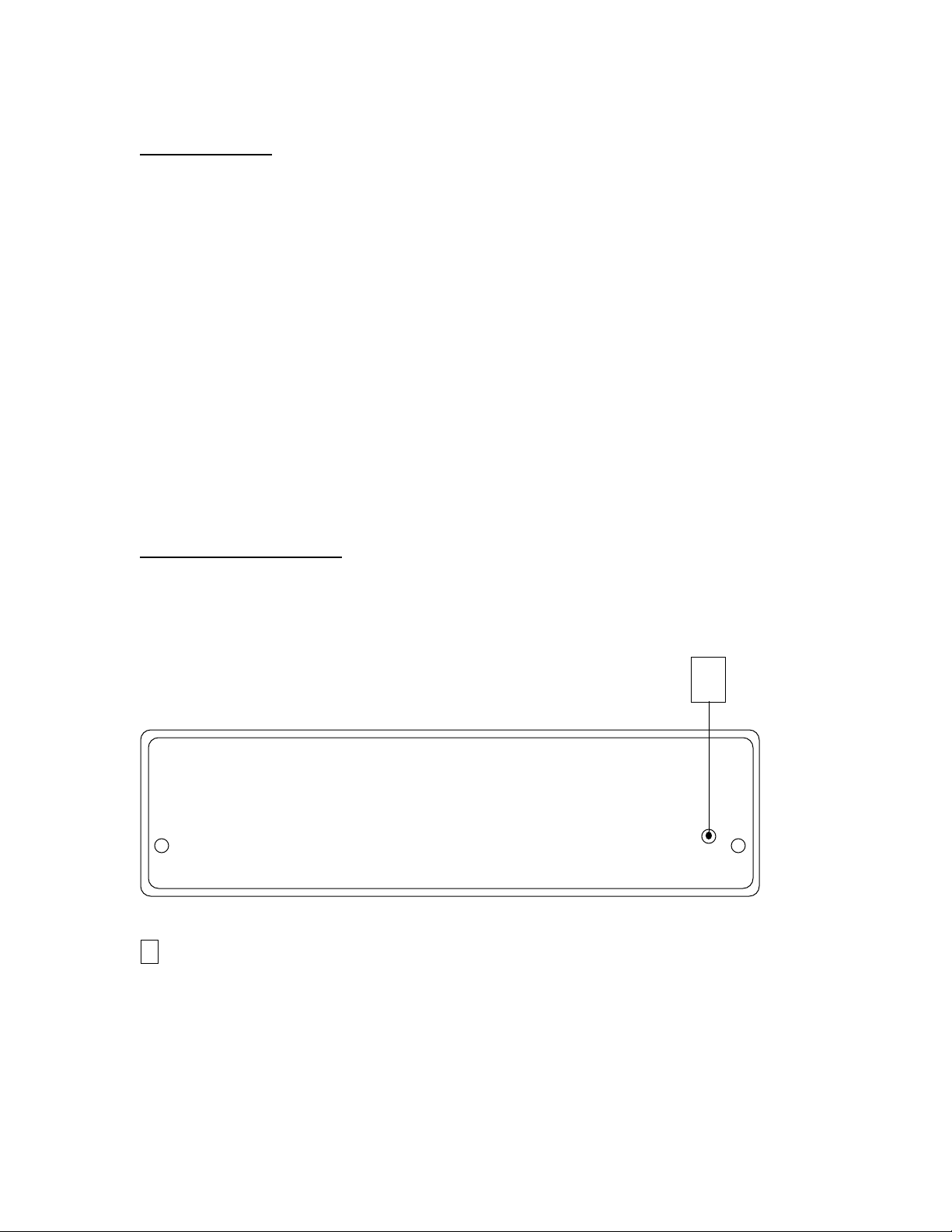
Front Panel
1
POWER on LED Indicator
1
1
Page 5
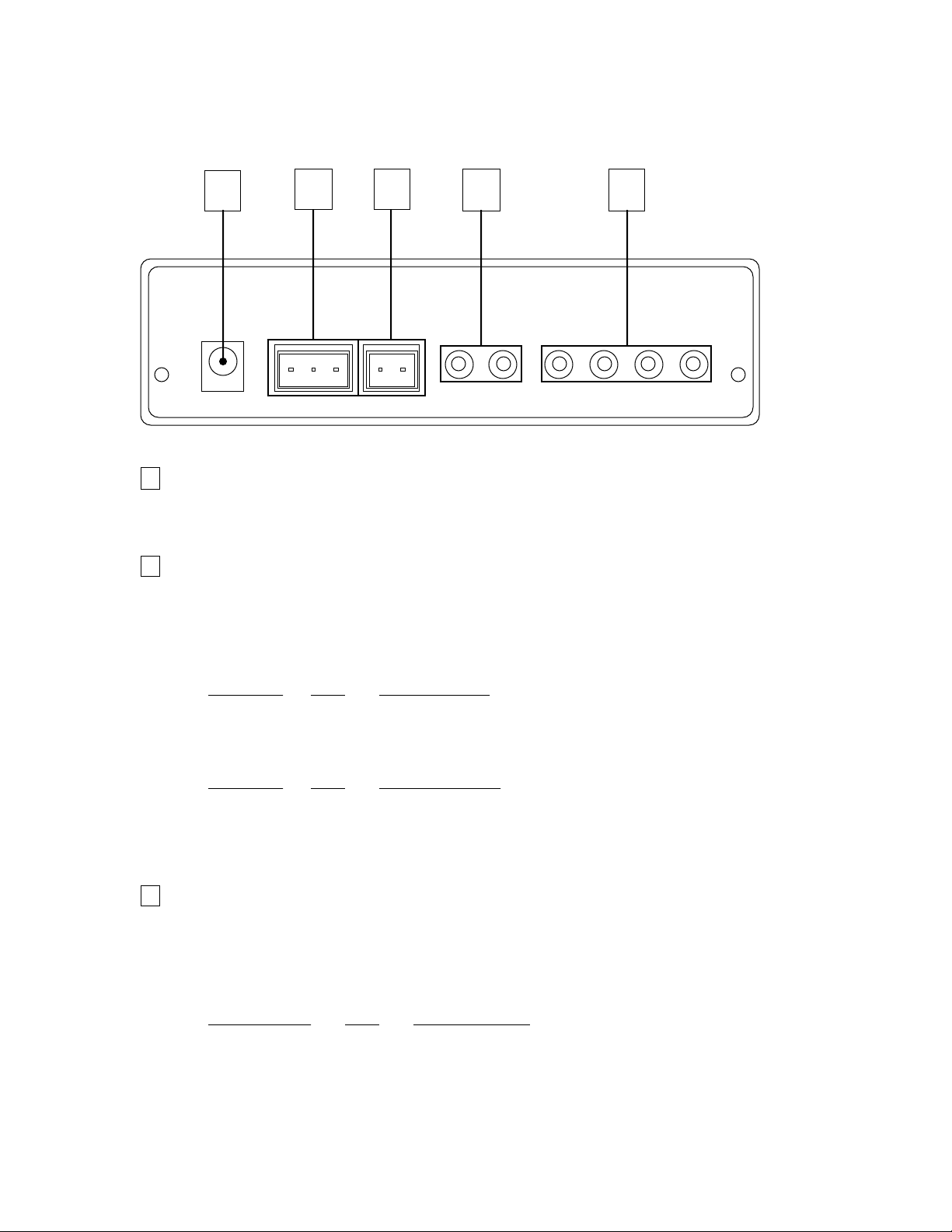
Rear Panel
1 2 3 4 5
1
POWER Connector
Input for 9VDC-500mA Power Supply (Supplied)
2
RS232 Connector
3 pin Terminal Block Connection to User Interfaces RS232 Control System Serial
Port.
Typical Wiring Configurations:
CIS-200 I/O 9-Pin D-Sub
TX > Pin 2 - RX
RX < Pin 3 - TX
GND - Pin 5 - GND
CIS-200 I/O 25-Pin D-Sub
TX > Pin 3 - RX
RX < Pin 2 - TX
GND - Pin 7 - GND
3
LOOP OUT Connector
2 pin Terminal Block Connection to Additional CIS-200 Series ExpansionInterface(s).
Typical Wiring Configuration:
LOOP OUT RS232
on CIS-200 I/O on expansion
TX > RX
GND - GND
2
Page 6
4
S-LINK - A1 Connectors
Two 1/8” (3.5mm) mini phone jacks. Parallel output of one Control-A1 channel.
Supports daisy chain connection of up to ten devices. Note that the CIS-200 counts as
one device.
5
S-LINK - CONTROL-S Connectors
Four 1/8” (3.5mm) mini phone jacks. Individual outputs for four Control-S channels.
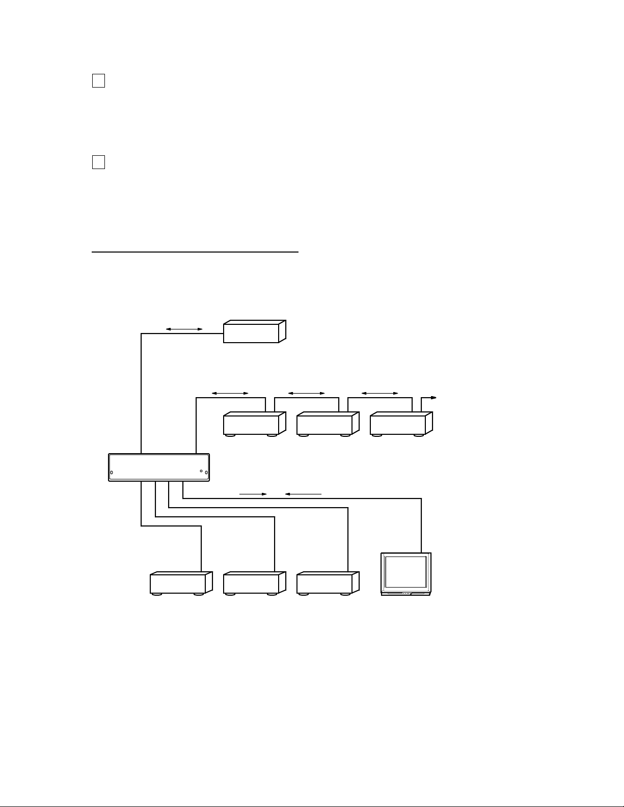
Typical System Configuration
The illustration below represents a typical system setup.
RS232
CONTROL-A1
CIS-200
CONTROL-S
CABLES
DATA
CABLE
DVD player DSS
User Interface
Touch Screen,
Computer, etc.
Receiver MD deckCD changer
DATA DATADATA
DATA STATUS
VCR
Up to Ten
Devices
TV
3
Page 7

CIS-200 RS-232 Protocol
Overview
Transfer Format
Transfer Rate 9600bps
Character Length 8 bits
Parity Check None
Start Bit 1
Stop Bit 1
ID Number
CIS-200 ID Number = 0
Send Strings:
A1 Send Strings
Send A1 Data
Request A1 Data
Control-S Send Strings
Send Control-S Data
Send Control-S Data Continuous
Request Control-S Status
Stop ALL Data
Return/Respond Strings:
A1 Return/Respond Strings
Command Sent ACK
Command Sent NACK (busy)
Receive Data ACK
Receive Data NACK (busy)
Control-S Return/Respond Strings
Command Sent ACK
Continuous Command Sent ACK
Receive Control-S Status
A1/Control-S Common Return/Respond Strings
All OFF ACK
4
Page 8
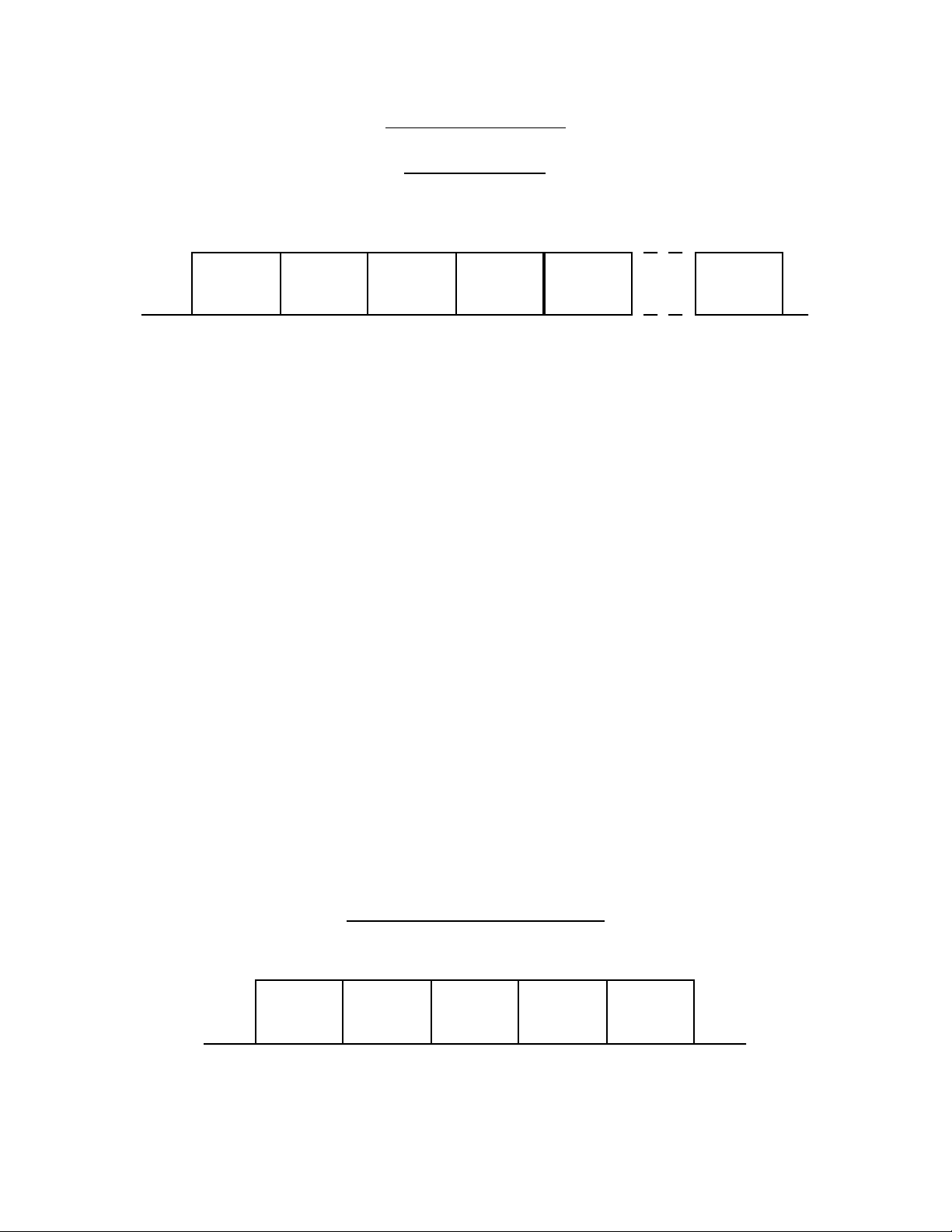
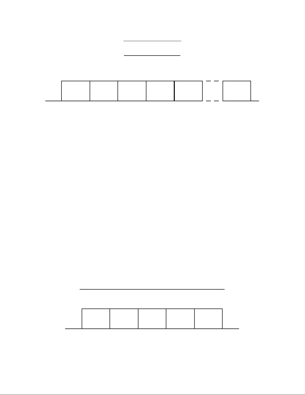
Command Number 1
Send A1 Data
st
1
Byte 2
Attention
Byte
nd
Byte 3
Command
Number
rd
Byte 4
Number
of Bytes
th
Byte
Product
code
5
th
Data
Byte
Data
1st Byte: Attention Byte
<8xH> 80H logically OR’d with ID number (80H for CIS-200).
2nd Byte: Command Number
<1> Send A1 Data
3rd Byte: Number of Bytes
The 3rd byte is equal to the total number of bytes including the 4th byte (Product Code)
to the last data byte.
4th Byte: Product Code
5th Byte: Data
Data can be from 1 to 19 bytes in length
Example: <CD1> <PLAY>
st
1
Byte 2
nd
01H80H 70H02H 01H
Attention
Byte
Command
Number
Byte 3
rd
Byte 4
Number
of Bytes
th
Byte
Product
code:
CD 1
th
5
Byte
Request
code:
PLAY
5
Page 9
Command Number 2
Request A1 Data
st
1
Byte 2
Attention
Byte
nd
Byte 3
Command
Number
rd
Byte 4
Number
of Bytes
th
Byte
Product
code
5
th
Data
Byte
Data
1st Byte: Attention Byte
<8xH> 80H logically OR’d with ID number (80H for CIS-200).
2nd Byte: Command Number
<2> Request A1 Data
3rd Byte: Number of Bytes
The 3rd byte is equal to the total number of bytes including the 4th byte (Product Code)
to the last data byte.
4th Byte: Product Code
5th Byte: Data
Data can be from 1 to 19 bytes in length
Example: <CD3> <TRACK TEXT REQUEST>
st
1
Byte 2
nd
02H80H 72H02H 28H
Attention
Byte
Command
Number
Byte 3
rd
Byte 4
Number
of Bytes
th
Byte
Product
code:
CD 3
th
5
Byte
Request
code:
TRACK
TEXT REQ
6
Page 10
Responses to Send A1 Data
After initiating a Command Number 1 (Send A1 Data) an ‘ACK’ or ‘NACK’ response
must be received before initiating next command.
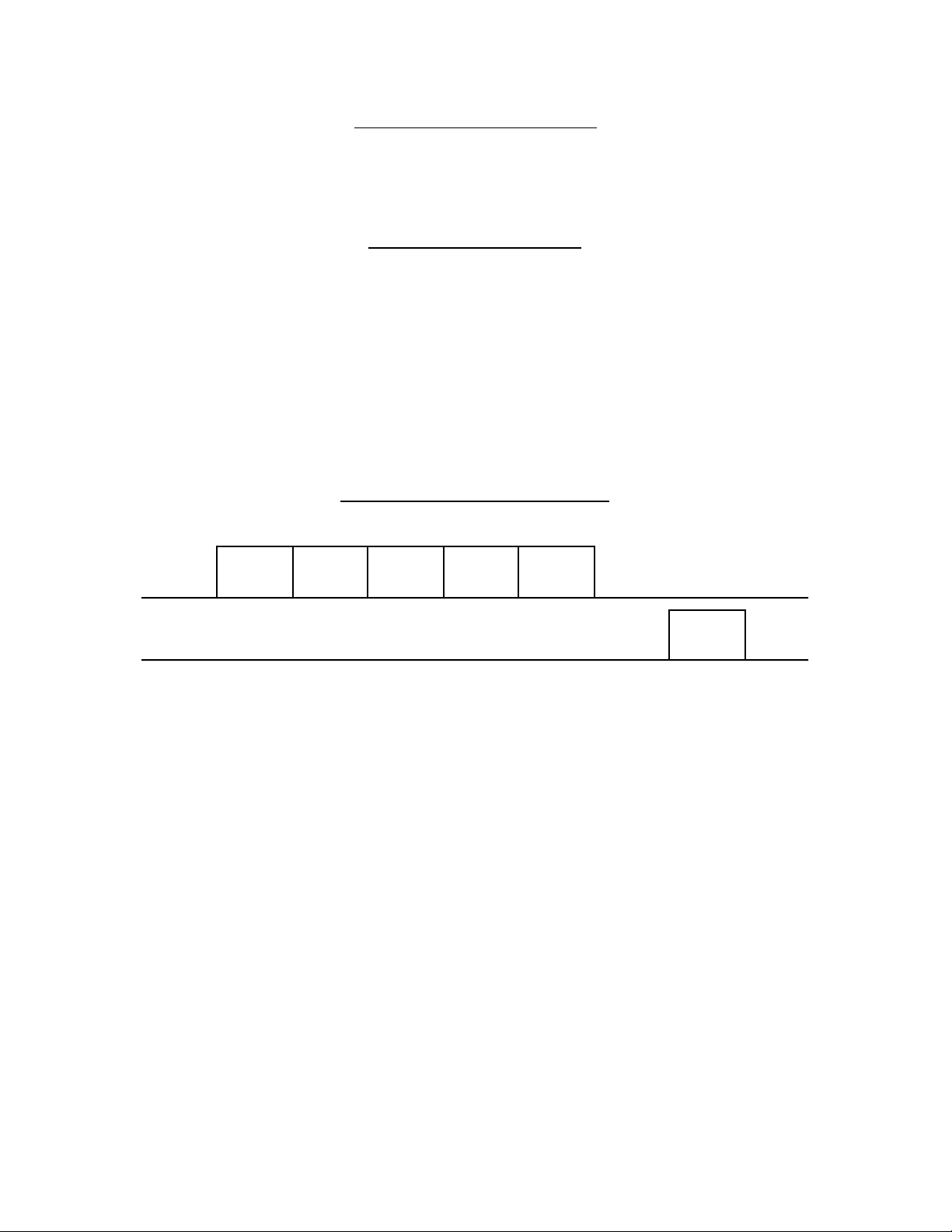
Command Sent ACK
1 Byte: Response
<FDH> Command acknowledged. A1 data sent.
Example: <CD 1> <PLAY >
CD 1 PLAY
TX
RX
01H80H 70H02H
01H
FDH
Command
Sent ACK
7
Page 11
Responses to Send A1 Data
After initiating a Command Number 1 (Send A1 Data) an ‘ACK’ or ‘NACK’ response
must be received before initiating next command.
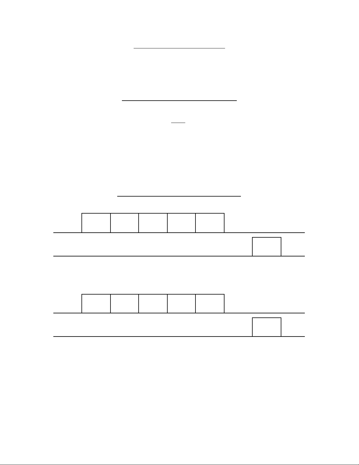
Command Sent NACK (busy)
1 Byte: Response
<FEH> Command received. A1 data NOT sent
Example: <AMP> <POWER ON>
AMP POWER ON
TX
RX
TX
RX
01H80H A0H02H
01H80H A0H02H
41H
FEH
Command
Sent NACK
AMP POWER ON
41H
FDH
Command
Sent ACK
8
Page 12
Responses to Request A1 Data
After initiating Command Number 2 (Request A1 Data) an ‘ACK’ or ‘NACK’ response
must be received before initiating next command.
Receive Data ACK
1st Byte: Response
<FDH> Command acknowledged. A1 data sent.
2nd Byte: Product Code
3rd Byte: Data
Example: <CD3> <TRACK TEXT REQUEST>
TX
RX
TX
RX
TX
RX
st
1
Byte 3
nd
2
72HFDH 00H xxH
Receive
Data ACK
th
Product
Code
Byte
45H48H 4CH 50H 00H 00H
ASCII
‘H’
ASCII
TRACK
CD 3
TEXT REQ
02H80H 72H03H 28H
Byte
rd
Byte 4
th
Byte 5
th
Byte
28H
Language
Code
11
th
Byte
Byte 20
‘P’
th
Byte7
‘E’
TRACK
TEXT DATA
th
9
Byte8
ASCII
‘L’
Track No.
th
10
ASCII
Track No.
00H
Current Track
th
6
Byte
xxH
Copy Control
Flag
th
continued
Byte
9
Page 13

Responses to Request A1 Data
After initiating Command Number 2 (Request A1 Data) an ‘ACK’ or ‘NACK’ response
must be received before initiating next command.
Receive Data NACK (busy)
1 Byte: Response
<FEH> Command received. A1 data NOT sent
VOLUME
AMP
POSITION REQ
TX
RX
TX
RX
02H80H A0H02H
02H80H A0H02H
AMP
VOLUME
POSITION REQ
21H
21H
FDH
Command
Sent ACK
FEH
Command
Sent NACK
A0H
AMP
POSITION DATA
7AH
VOLUME
10
Page 14
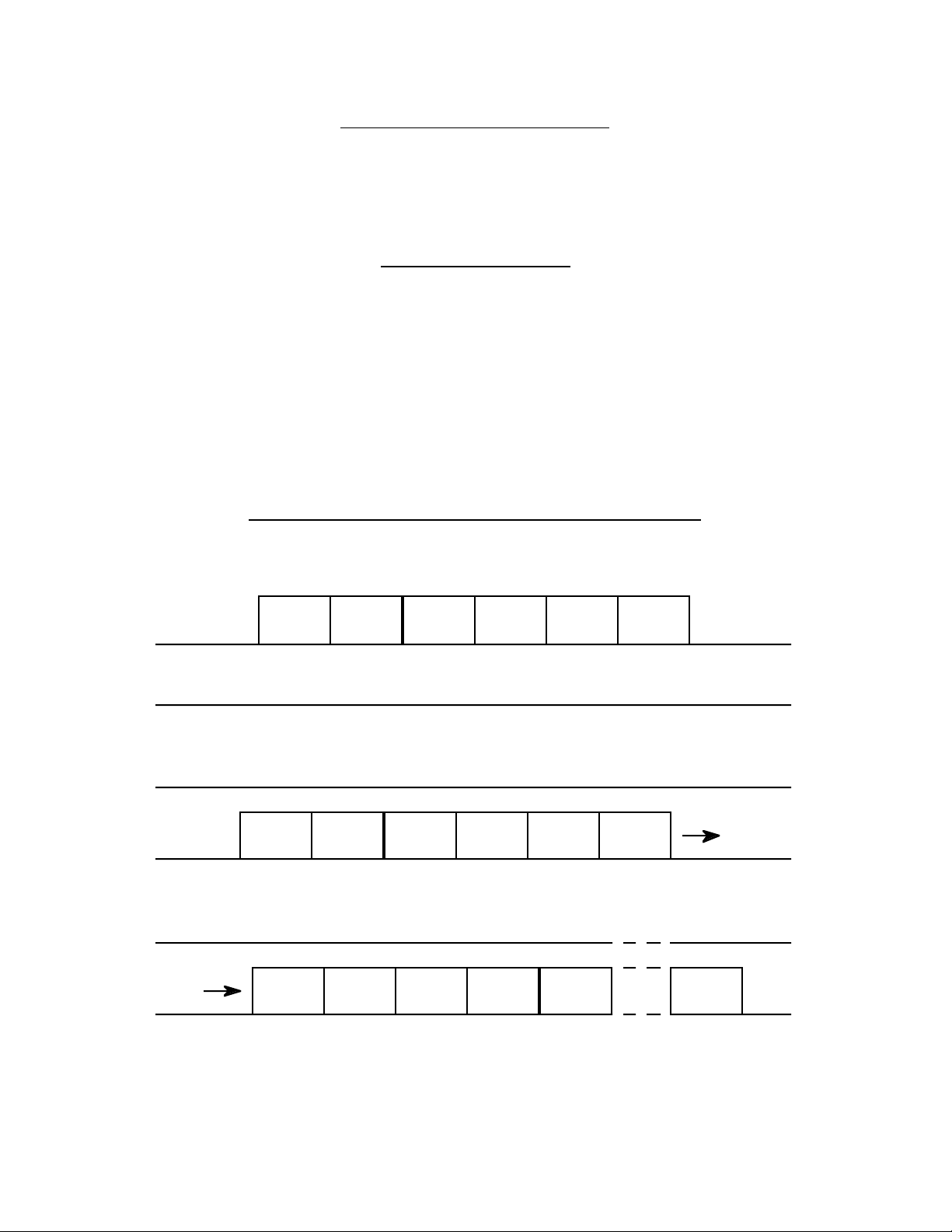
Command Number 3
Send Control-S Data
st
1
Byte 2
Attention
Byte
nd
Byte 3
Command
Number
rd
Byte 4
Channel
th
Byte
Product
code - HI
1st Byte: Attention Byte
<8xH> 80H logically OR’d with ID number (80H for CIS-200).
2nd Byte: Command Number
<3> Send Control-S Data
3rd Byte: Channel
Control-S channel 1 through 4
4th Byte: Product Code HI Byte
5th Byte: Product Code LO Byte
th
5
Byte
Product
code - LO
th
Byte
6
Command
6th Byte: Command
st
1
Byte 2
Attention
Byte
Example: <VCR1> <PLAY>
nd
Byte
rd
3
Byte 4
th
Byte
th
5
03H80H 00H01H 12H
Command
Number
Control-S
Channel
Product code: VCR1
11
LO ByteHI Byte
Byte
th
6
Byte
24H
Command:
PLAY
Page 15
Command Number 4
Send Control-S Data Continuous
st
1
Byte 2
Attention
Byte
nd
Byte 3
Command
Number
rd
Byte 4
Channel
th
Byte
Product
code - HI
1st Byte: Attention Byte
<8xH> 80H logically OR’d with ID number (80H for CIS-200).
2nd Byte: Command Number
<4> Send Control-S Data Continuous
3rd Byte: Channel
Control-S channel 1 through 4
4th Byte: Product Code HI Byte
5th Byte: Product Code LO Byte
th
5
Byte
Product
code - LO
th
Byte
6
Command
6th Byte: Command
st
1
Byte 2
Attention
Byte
Example: <TV> <VOLUME +>
nd
Byte
rd
3
Byte 4
th
Byte
th
5
04H80H 00H03H 10H
Command
Number
Control-S
Channel
Product code: TV
12
LO ByteHI Byte
Byte
th
6
Byte
13H
Command:
VOLUME +
Page 16
Command Number 5
Request Control-S Status
st
1
Byte 2
Attention
Byte
nd
Byte 3
Command
Number
rd
Byte
Channel
1st Byte: Attention Byte
<8xH> 80H logically OR’d with ID number (80H for CIS-200).
2nd Byte: Command Number
<5> Request Control-S Status
3rd Byte: Channel
Control-S channel 1 through 4
Example: <REQUEST STATUS> <Channel 4>
st
1
Byte 2
nd
Byte 3
rd
Byte
05H80H 04H
Attention
Byte
Command
Number
13
Control-S
Channel
Page 17
Responses to Send Control-S Data
After initiating either Command Number 3 (Send Control-S Data) or #4 (Send Control-S
Data Continuous) an ‘ACK’ response must be received before initiating next command.
Command Sent ACK or Continuous Command Sent ACK
1 Byte: Response
<FDH> Command acknowledged. Control-S data sent.
Example: <VCR 1> <PLAY >
PLAYVCR1
TX
RX
03H80H 00H01H
12H
24H
FDH
Command
Sent ACK
14
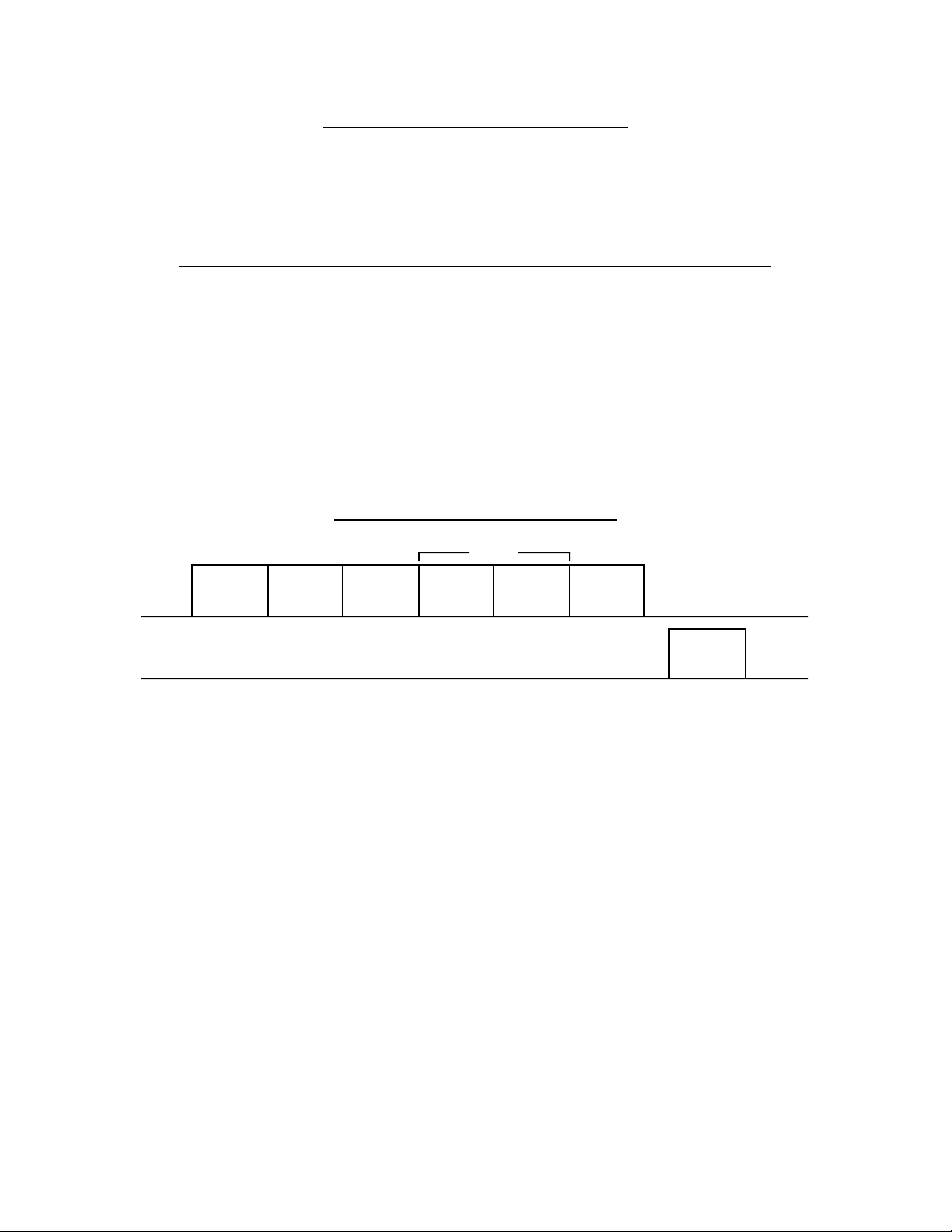
Page 18

Response to Request Control-S Status
After initiating Command Number 5 (Request Control-S Status).
Receive Control-S Status
1st Byte: Response
<FDH> Command acknowledged. Control-S data sent.
2nd Byte: Channel
Control-S channel 1 through 4
3rd Byte: Status
0 = ‘OFF’ , 1 = ‘ON’
Example: <REQUEST STATUS > <Channel 4>
TX
RX
Request Control-S
Status Channel 4
05H80H 04H
FDH
Command
Sent ACK
04H
Channel 4
01H
‘ON’
15
Page 19
Control-S Commands / Responses
Stop All Data
This command stops all Control-S continuous data being sent, and also stops A1 data from
being received. This must be sent after any continuous command has been initiated,
otherwise the next command(s) sent will be ignored.
1 Byte: Attention Byte
<9xH> 90H logically OR’d with ID number (90H for CIS-200).
All Off ACK
1 Byte: Response
<FDH> Command acknowledged. All data stopped
TX
RX
Example: <AMP/VOL+> <STOP ALL DATA>
04H80H 00H01H
AMP VOLUME +
40H
12H
FDH
Command
Sent ACK
STOP ALL DATA
90H
FDH
All Off ACK
16
Page 20

Programmers Notes:
Since CONTROL-A1 is a half-duplex "network" running at an equivalent baud rate of
approximately 600 bps, it is recommended that the following guidelines be observed to
achieve maximum efficiency:
1. The CIS-200 Command #1 (Send A1 Data), is intentionally designed NOT to read back
the A1 returned data, as to achieve a faster response time. It is recommended to use
Command #1 for commands such as "PLAY", "STOP", "PAUSE", etc. that would require
instant response.
2. The CIS-200 Command #2 (Request A1 Data), will read back ALL A1 data on the A1
bus immediately after "ACK" is received. It is recommended to use this command only
when data reception is necessary (i.e. obtaining product status’s) as to minimize A1 "data
clog". After data is received, a "Stop ALL Data" Command (90H) or a subsequent
Command #1 should be sent to minimize data throughput.
CIS-200 Protocol Summary
Send Strings
Command
Header No.
Send A1 Data <80H> <1> <Number of Bytes> <Product Code> <Data>
Request A1 Data <80H> <2> <Number of Bytes> <Product Code> <Data>
Send Control-S Data <80H> <3> <Channel> < Prod_Hi> <Prod_Lo> <Data>
Send Control-S Continuous <80H> <4> <Channel> < Prod_Hi> <Prod_Lo> <Data>
Request Control-S Status <80H> <5> <Channel>
Stop ALL Data <90H>
Return/Respond Strings
A1 Responses: (after initiating command number 1)
Command Sent ACK <FDH>
Command Sent NACK (busy) <FEH>
A1 Responses: (after initiating command number 2)
Receive Data ACK <FDH> <Product Code> <Data>
Receive Data NACK (busy) <FEH>
Control-S Responses: (after initiating commands number 3-4)
Command Sent ACK <FDH>
Continuous Command Sent ACK <FDH>
Control-S Responses: (after initiating command number 5)
Receive Control-S Status <FDH> <Channel> <Status>
A1 / Control-S Common Response
All OFF ACK <FDH>
17
Page 21

Category: AMP Control-A1 Product Code : A0
REQUEST CODES ANSWER CODES
5th byte CODE NAME 3rd byte CODE NAME
04 MUTE OFF 0E NO FUNCTION
05 MUTE ON 0F NON-EXECUTABLE
06 ADAPTOR ON 1B NO FUNCTION NAME
07 ADAPTOR OFF 1E WRITE COMPLETE
08 MONITOR ON 2A FUNCTION NAME DATA
09 MONITOR OFF 40 POWER OFF
0A S. DIRECT ON 41 POWER ON
0B S. DIRECT OFF 51 STATUS DATA
0E STATUS REQ. 70 MODEL NAME DATA
12 VOLUME + 74 MODEL DATA
13 VOLUME 1E OFF CODE
21 VOLUME POSITION REQ.
2A FUNCTION NAME REQ.
33 FUNCTION CHANGE REQ.
40 POWER OFF
41 POWER ON
42 REMOTE OFF
43 REMOTE ON
44 MODEL DATA REQ.
4F MONITOR M-BUS REQ.
70 MODEL NAME REQ.
92 FUNC. NAME WRITE
19
Page 22

Correspondence between Request and Answer Codes
yte
te
Category: AMP Control-A1 Product Code : A0
REQ ANS CODE NAME CODE REQ : 6th byte REQ : 7th byte REQ : 8th byte REQ : 9th byte REQ : 10th b
5th byte 3rd byte LENGTH ANS : 4th byte ANS : 5th byte ANS : 6th byte ANS : 7th byte ANS : 8th by
0E STATUS REQ. 5
51 STATUS DATA 7 AUDIO FUNC. VIDEO FUNC. DATA1 TERMINATING BYTE
A FUNC. DATA V FUNC. DATA DATA1: 00~FF
00 : TUNER b7b6b5:
01 : PHONO 000 fixed
02 : CD b4: ADAPTOR
03 : DAT 0: OFF
04 : MD 1: ON
05 : TAPE1 b3: MONITOR
06 : TAPE2 0: OFF
07 : DIGITAL1 1: ON
08 : DIGITAL2 b2: S. DIRECT
09 : DIGITAL3 0: OFF
0A : AUX1 1: ON
0B : AUX2 b1: MUTE
0C~0F reserved 0: OFF
10 : VIDEO1 10 : VIDEO1 1: ON
11 : VIDEO2 11 : VIDEO2 b0: POWER
12 : VIDEO3 12 : VIDEO3 0: OFF
13 : VIDEO4 13 : VIDEO4 1: ON
14 : VIDEO5 14 : VIDEO5
15 : LDP 15 : LDP
16 : TV 16 : TV
17 : DBS 17 : DBS
18 : VCD 18 : VCD
19 : DVD 19 : DVD
1A~FD reserved 1A~FD reserved
2A FUNCTION NAME REQ. 6 FUNCTION CODE
2A FUNCTION NAME DATA 17 FUNCTION CODE ASCII DATA x 13 byte (Pad "00H" when less than 13 characters)
00 : TUNER
01 : PHONO
02 : CD
03 : DAT
04 : MD
05 : TAPE1
06 : TAPE2
07 : DIGITAL1
08 : DIGITAL2
09 : DIGITAL3
0A : AUX1
0B : AUX2
0C~0F reserved
10 : VIDEO1
11 : VIDEO2
12 : VIDEO3
13 : VIDEO4
14 : VIDEO5
15 : LDP
16 : TV
17 : DBS
18 : VCD
19 : DVD
1A~FD reserved
or 1B NO FUNCTION NAME 3
21 VOLUME POSITION REQ. 5
21 VOLUME POSITION DATA 4 A/D DATA 00-FF
20
Page 23

Correspondence between Request and Answer Codes
yte
5th byte 3rd byte LENGTH ANS : 4th byte ANS : 5th byte ANS : 6th byte ANS : 7th byte ANS : 8th byte
R
D
Category: AMP Control-A1 Product Code : A0
REQ ANS CODE NAME CODE REQ : 6th byte REQ : 7th byte REQ : 8th byte REQ : 9th byte REQ : 10th b
92 • • • FUNCTION NAME WRITE 19 FUNCTION CODE ASCII DATA x 13 byte (Pad "00H" when less than 13 characters)
00 : TUNER
01 : PHONO
02 : CD
03 : DAT
04 : MD
05 : TAPE1
06 : TAPE2
07 : DIGITAL1
08 : DIGITAL2
09 : DIGITAL3
0A : AUX1
0B : AUX2
0C~0F reserved
10 : VIDEO1
11 : VIDEO2
12 : VIDEO3
13 : VIDEO4
14 : VIDEO5
15 : LDP
16 : TV
17 : DBS
18 : VCD
19 : DVD
1A~FD reserved
44 MODEL DATA REQ. 5
74 MODEL DATA 8 AUDIO 1 AUDIO 2 VIDEO 1 VIDEO 2 DATA1
Set the bit for possessed function to "1". b7b6b5:
b0 : TUNER b0 : DIGITAL2 b0 : VIDEO1 b0 : VCD 000 fixed
b1 : PHONO b1 : DIGITAL3 b1 : VIDEO2 b1 : DVD b4: ADAPTOR
b2 : CD b2 : AUX1 b2 : VIDEO3 b2 : reserved 0: OFF
b3 : DAT b3 : AUX2 b3 : VIDEO4 b3 : reserved 1: ON
b4 : MD b4 : reserved b4 : VIDEO5 b4 : reserved b3: T. MONITO
b5 : TAPE1 b5 : reserved b5 : LD b5 : reserved 0: OFF
b6 : TAPE2 b6 : reserved b6 : TV b6 : reserved 1: ON
b7 : DIGITAL1 b7 : reserved b7 : DBS b7 : reserved b2: S. DIRECT
0: OFF
1: ON
b1: MUTE
0: OFF
1: ON
b0: SURROUN
0: OFF
1: ON
21
Page 24

Correspondence between Request and Answer Codes
yte
5th byte 3rd byte LENGTH ANS : 4th byte ANS : 5th byte ANS : 6th byte ANS : 7th byte ANS : 8th byte
Category: AMP Control-A1 Product Code : A0
REQ ANS CODE NAME CODE REQ : 6th byte REQ : 7th byte REQ : 8th byte REQ : 9th byte REQ : 10th b
33 FUNCTION CHANGE REQ. 8 AUDIO VIDEO TERMINATING BYTE
A FUNC. DATA V FUNC. DATA 00~FF
00 : TUNER
01 : PHONO
02 : CD
03 : DAT
04 : MD
05 : TAPE1
06 : TAPE2
07 : DIGITAL1
08 : DIGITAL2
09 : DIGITAL3
0A : AUX1
0B : AUX2
0C~0F reserved
10 : VIDEO1 10 : VIDEO1
11 : VIDEO2 11 : VIDEO2
12 : VIDEO3 12 : VIDEO3
13 : VIDEO4 13 : VIDEO4
14 : VIDEO5 14 : VIDEO5
15 : LDP 15 : LDP
16 : TV 16 : TV
17 : DBS 17 : DBS
18 : VCD 18 : VCD
19 : DVD 19 : DVD
FE : MUTE FE : MUTE
FF : Unchanged FF : Unchanged
51 STATUS DATA 7 AUDIO FUNC. VIDEO FUNC. DATA1 TERMINATING BYTE
A FUNC. DATA V FUNC. DATA DATA1: 00~FF
00 : TUNER b7b6b5:
01 : PHONO 000 fixed
02 : CD b4: ADAPTOR
03 : DAT 0: OFF
04 : MD 1: ON
05 : TAPE1 b3: MONITOR
06 : TAPE2 0: OFF
07 : DIGITAL1 1: ON
08 : DIGITAL2 b2: S. DIRECT
09 : DIGITAL3 0: OFF
0A : AUX1 1: ON
0B : AUX2 b1: MUTE
0C~0F reserved 0: OFF
10 : VIDEO1 10 : VIDEO1 1: ON
11 : VIDEO2 11 : VIDEO2 b0: POWER
12 : VIDEO3 12 : VIDEO3 0: OFF
13 : VIDEO4 13 : VIDEO4 1: ON
14 : VIDEO5 14 : VIDEO5
15 : LDP 15 : LDP
16 : TV 16 : TV
17 : DBS 17 : DBS
18 : VCD 18 : VCD
19 : DVD 19 : DVD
1A~FD reserved 1A~FD reserved
70 MODEL NAME REQ. 5
70 MODEL NAME DATA 17 ASCII DATA x 14 byte (Exactly input upper- and lowercase letters with spaces padded with "00")
22
Page 25

Category: CD1, CD2, CD3 Control-A1 Product Code : 70, 71, 72
age
REQUEST CODES ANSWER CODES
5th byte CODE NAME 3rd byte CODE NAME
00 STOP KEY 00 STOP DONE
01 PLAY KEY 01 PLAY DONE
02 PAUSE KEY 02 EJECT DONE
03 PAUSE ON 03 PAUSE DONE
04 PEAK SEARCH 04 PEAK SEARCH DONE
0A NEXT 05 DISC CHANGE
0B PREV 06 TRACK LAST 30 S
0E STATUS REQ. 07 PGM PAUSE DONE
0F DISC DATA REQ. 09 ONE-TOUCH PLAY REQ.
10 CURSOR LEFT 0A DISC PRESENT
11 CURSOR RIGHT 0B 1 TRACK END
12 CURSOR UP 0D NO DISC
13 CURSOR DOWN 0E NO FUNCTION
14 CURSOR ENTER 0F CANNOT EXECUTE
19 FF 10 NO TRACK MEMO DATA
1A FR 12 NO TOC DATA
1B SLOW FF 13 NO TRACK TIME DATA
1C SLOW FR 14 UNLOAD ON
1E OFF CODE 15 NO DISC TEXT
20 DISC DELETE REQ. 16 NO TRACK TEXT
21 DISC MEMO REQ. 17 (NO ISRC DATA)
22 GROUP BIT REQ. 18 (NO POS DATA)
23 GROUP MEMO REQ. 19 NO GROUP MEMO DATA
26 OTHER TEXT REQ. 1A NO GROUP BIT DATA
28 TRACK TEXT REQ. 1B NO DISC MEMO DATA
2A DISC TEXT REQ. 1C NO DISC DELETE DATA
2C TOC DATA REQ. 1E WRITE COMPLETE
2D TRACK TIME REQ. 20 DISC DELETE DATA
33 DISC/TRACK PLAY 21 DISC MEMO DATA
34 DISC/TRACK PAUSE 22 GROUP BIT DATA
3C FADE IN REQ. 23 GROUP MEMO DATA
3D FADE OUT REQ. 26 OTHER TEXT DATA
40 POWER OFF 27 OTHER TEXT CONTINUED
41 POWER ON 28 TRACK TEXT DATA
42 REMOTE OFF 29 TRACK TEXT CONTINUED
43 REMOTE ON 2A DISC TEXT DATA
44 MODEL DATA REQ. 2B DISC TEXT CONTINUED
46 CONT. MODE 2C GROUP BIT DATA
48 ELASPED TIME OFF 2F ALL TEXT END
49 ELASPED TIME REQ. 30 NO DISC WITH NO.
4A 1 TRACK PAUSE MODE 31 DISC PRESENT WITH NO.
4B (TEXT CANCEL) 32 DISC CHANGE WITH NO.
63 TOC GET END 33 TRACK START (DISC TRACK)
64 TOC GET 34 ELASPED TIME
65 V. TOUCH MODE ON (RF) 35 TOC READ START
66 V. TOUCH MODE OFF 40 POWER OFF
67 V. TOUCH MODE ON (IR) 41 POWER ON
continued next page continued next p
23
Page 26

Category: CD1, CD2, CD3 Product Code : 70, 71, 72
REQUEST CODES continued ANSWER CODES continued
5th byte CODE NAME 3rd byte CODE NAME
70 MODEL NAME REQ. 45 FADE OUT START
72 POS DATA REQ. 47 PEAK REPEAT DONE
76 POINTER POSITION DATA 51 STATUS DATA
80 JOG + 66 V. TOUCH MODE EXIT
81 JOG - 67 IN V. TOUCH MODE
98 DISC MEMO WRITE 70 MODEL NAME DATA
99 GROUP MEMO WRITE 71 TOC DATA
9A TRACK MEMO WRITE 72 POS DATA
73 ISRC DATA
74 MODEL DATA
75 TRACK TIME DATA
24
Page 27

Correspondence between Request and Answer Codes
yte
te
Category: CD1, CD2, CD3 Control-A1 Product Code : 70, 71, 72
REQ ANS CODE NAME CODE REQ : 6th byte REQ : 7th byte REQ : 8th byte REQ : 9th byte REQ : 10th b
5th byte 3rd byte LENGTH ANS : 4th byte ANS : 5th byte ANS : 6th byte ANS : 7th byte ANS : 8th by
21 DISC MEMO REQ. 6 DISC No.
21 DISC MEMO DATA 17 DISC No. ASCII DATA x 13 bytes
01~99 (1 to 99)
00 (100)
9A~FE (100 to 200)
FF (Current Disc)
or 1B NO DISC MEMO DATA 3 ( DISC MEMO REQ. is received but no corresponding data exists.)
20 DISC DELETE REQ. 6 DISC No.
20 DISC DELETE DATA 17 DISC No. DELETE BIT DATA x 13 bytes
01~99 (1 to 99)
00 (100)
9A~FE (100 to 200)
FF (Current Disc)
or 1C NO DISC DELETE DATA 3 ( DISC DELETE REQ. is received but no corresponding data exists.)
23 GROUP MEMO REQ. 6 GROUP No.
23 GROUP MEMO DATA 17 GROUP No. ASCII DATA x 13 bytes
or 19 NO GROUP MEMO DATA 3 ( GROUP MEMO REQ. received but no corresponding data exists.)
22 GROUP BIT REQ. 6 GROUP No.
22 GROUP BIT DATA 17 GROUP No. GROUP BIT DATA x 13 bytes (DISC 1 to 104)
(No Disc =0, Disc present =1)
1st byte 2nd byte 3rd to 12th byte 13th byte
bit 0 DISC 1 DISC 9 • • • DISC 97
bit 1 DISC 2 DISC 10 • • • DISC 98
bit 2 DISC 3 DISC 11 • • • DISC 99
bit 3 DISC 4 DISC 12 • • • DISC 100
bit 4 DISC 5 DISC 13 • • • DISC 101
bit 5 DISC 6 DISC 14 • • • DISC 102
bit 6 DISC 7 DISC 15 • • • DISC 103
bit 7 DISC 8 DISC 16 • • • DISC 104
2C GROUP BIT DATA 17 GROUP No. GROUP BIT DATA x 13 bytes (DISC 105 to 200)
Transmitted after '22' for DISC 105 and subsequent discs, if any. The last byte will be '00"
or 1A NO GROUP BIT DATA 3 ( GROUP BIT REQ. received but no corresponding data exists.)
2C TOC DATA REQ. 6 DISC No.
71 TOC DATA 9 DISC No. 5th byte 6th byte 7th byte 8th byte
01~99 (1 to 99) FTNO LTNO LMIN LSEC
00 (100) (First track No.) (Last track No.) 9th byte
9A~FE (100 to 200) LFRM
FF (Current Disc)
or 12 NO TOC DATA 3 ( TOC DATA REQ. is received but no corresponding data exists.)
2D TRACK TIME REQ. 7 DISC No. TNO (track No.)
75 TRACK TIME DATA 7 DISC No. TNO (track No.) MIN SEC
01~99 (1 to 99)
00 (100)
9A~FE (100 to 200)
FF (Current Disc)
or 13 NO TRACK TIME DATA 3 ( TRACK TIME REQ. is received but no corresponding data exists.)
25
Page 28

Correspondence between Request and Answer Codes
yte
te
d
Category: CD1, CD2, CD3 Control-A1 Product Code : 70, 71, 72
REQ ANS CODE NAME CODE REQ : 6th byte REQ : 7th byte REQ : 8th byte REQ : 9th byte REQ : 10th b
5th byte 3rd byte LENGTH ANS : 4th byte ANS : 5th byte ANS : 6th byte ANS : 7th byte ANS : 8th by
0E STATUS REQ. 5
51 STATUS DATA 8 DATA1 DATA2 00H (fixed) DISC No. Track No.
b7 : fixed to 0 b7 : 01~99 (1 to 99) 00 while stoppe
b6 : fixed to 0 0 : TOC not read 00 (100)
b5 : NO DISC? 1 : TOC read 9A~FE (100 to 200)
0 : Disc present b6 : FF (Current Disc)
1 : No disc 0 : 1DISC mode
b4 : POWER 1 : ALL DISCS
0 : ON b5b4 :
1 : OFF 00 : REPEAT off
b3b2b1b0 : 01 : REPEAT all
0000 : STOP 10 : REPEAT 1
0001 : PLAY 11 : REPEAT A-B
0010 : PAUSE b3b2b1b0 :
0011 : OPEN 0000 : CONTINUE
0100 : TOC PLAY 0001 : SHUFFLE
0101~1110 rsrvd 0010 : PROGRAM
1111 play disabled 0011 : reserved
0100 : PGM1
0101 : PGM2
0110 : PGM3
0111 : reserved
44 MODEL DATA REQ. 5
74 MODEL DATA 5 DISC NO. FEATURE
0F DISC DATA REQ. 3
50 DISC DATA 4 DISC Information
01~99 (1 to 99) b7 : fixed to 0
00 (100) b6 : fixed to 0
9A~FE (100 to 200) b5 : fixed to 0
FF (Current Disc) b4 : GUI support
0 : not supported
1 : supported
b3 : GROUP FILE
0 : not available
1 : available
b2 : LEVEL FILE
0 : not available
1 : available
b1 : DELETE FILE
0 : not available
1 : available
b0 : DISC MEMO
0 : not available
1 : available
b7b6 : Fixed to 0
b5 : TRACK TEXT b2 : LEVEL FILE
0 : not available 0 : not available
1 : available 1 : available
b4 : DISC TEXT b1 : DELETE FILE
0 : not available 0 : not available
1 : available 1 : available
b3 : TRACK MEMO b0 : DISC MEMO
0 : not available 0 : not available
1 : available 1 : available
26
Page 29

Correspondence between Request and Answer Codes
yte
te
s
the
s
the
s
the
Category: CD1, CD2, CD3 Control-A1 Product Code : 70, 71, 72
REQ ANS CODE NAME CODE REQ : 6th byte REQ : 7th byte REQ : 8th byte REQ : 9th byte REQ : 10th b
5th byte 3rd byte LENGTH ANS : 4th byte ANS : 5th byte ANS : 6th byte ANS : 7th byte ANS : 8th by
2A DISC TEXT REQ. 6 DISC No. (if no text is available for the disc, disc memo will be returned, if any)
2A DISC TEXT DATA 20 DISC No. Language Code Copy Control flag ASCII DATA x 14 bytes (pad "00H")
01~99 (1 to 99)
00 (100)
9A~FE (100 to 200)
FF (Current Disc)
2B DISC TEXT CONTINUED 20 PACKET No. ASCII DATA x 16 bytes (the last data is "00H")
Hex, 02 or greater Note: Text data has an undefined length so that it is divided into 16 byte code
and transmitted at 15-ms intervals. The last data is "00H " and any
subsequent data will be padded with "00H". If no more packets are
needed subsequent packet transmission can be canceled by sending
TEXT CANCEL code to the CD player.
or 15 NO DISC TEXT 3 (DISC TEXT REQ. has been received but no corresponding data exists.)
28 TRACK TEXT REQ. 6 No. 00 indicates the current track (If no text is available, track memo will be returned (if any)
28 TRACK TEXT DATA 20 Track No. Language Code Copy Control flag ASCII DATA x 14 bytes (pad "00H")
29 TRACK TEXT CONTINUED 20 PACKET No. ASCII DATA x 16 bytes (the last data is "00H")
Hex, 02 or greater Note: Text data has an undefined length so that it is divided into 16 byte code
and transmitted at 15-ms intervals. The last data is "00H " and any
subsequent data will be padded with "00H". If no more packets are
needed subsequent packet transmission can be canceled by sending
TEXT CANCEL code to the CD player.
or 16 NO TRACK TEXT 3 (TRACK TEXT REQ. has been received but no corresponding data exists.)
26 OTHER TEXT REQ. 7 DATA1 DATA2
26 OTHER TEXT DATA 20 DATA Language Code Copy Control flag ASCII DATA x 14 bytes (pad "00H")
27 OTHER TEXT REQ. 20 PACKET No. ASCII DATA x 16 bytes (the last data is "00H")
Hex, 02 or greater Note: Text data has an undefined length so that it is divided into 16 byte code
and transmitted at 15-ms intervals. The last data is "00H " and any
subsequent data will be padded with "00H". If no more packets are
needed subsequent packet transmission can be canceled by sending
TEXT CANCEL code to the CD player.
or 1F NO OTHER TEXT 3 (OTHER TEXT REQ. has been received but no corresponding data exists.)
• • • 33 TRACK START (ACCESS END) 7 DISC No. Track No. MIN SEC
Equivalent to conventional track gap code. 01~99 (1 to 99) Track length (0AAH if unknown)
Transmitted including the track length,
after an access or upon any change in TNO 9A~FE (100 to 200)
00 (100)
FF (Current Disc)
• • • 34 ELAPSED TIME 7 Track No. INDEX No. MIN SEC
Transmitted if the elapsed time when ELAPSED TIME REQ. has been received. Transmitted at 200-ms intervals during FF/FR
• • • 32 DISC CHANGE with No. 4 DISC No.
Transmitted when changing the disc. 01~99 (1 to 99)
00 (100)
9A~FE (100 to 200)
FF (Current Disc)
27
Page 30

Correspondence between Request and Answer Codes
yte
te
Category: CD1, CD2, CD3 Control-A1 Product Code : 70, 71, 72
REQ ANS CODE NAME CODE REQ : 6th byte REQ : 7th byte REQ : 8th byte REQ : 9th byte REQ : 10th b
5th byte 3rd byte LENGTH ANS : 4th byte ANS : 5th byte ANS : 6th byte ANS : 7th byte ANS : 8th by
72 POS DATA REQ 6 DISC No.
72 POS DATA 12 DISC No.
01~99 (1 to 99)
00 (100)
9A~FE (100 to 200)
FF (Current Disc)
or 18 NO POS DATA 3 (POS DATA REQ. has been received but no corresponding data exists.)
73 ISRC DATA REQ. 5
73 ISRC DATA 17 ISRC DATA x14 bytes (Q data address 3 information)
or 17 NO ISRC DATA 3 (ISRC DATA REQ. has been received but no corresponding data exists.)
33 DISC/TRACK PLAY 7 DISC No. Track No. (PLAY by directly specifying the disc and track)
34 DISC/TRACK PAUSE 7 DISC No. Track No. (PAUSE by directly specifying the disc and track)
32 DISC CHANGE with No. 4 DISC No. Transmitted when changing the disc
30 NO DISC (with No.) 4 DISC No. Transmitted when no disc is found for 33 or 34 command
35 TOC READ START 4 DISC No. Transmitted when starting TOC read after chucking the disc
31 DISC PRESENT with No. 4 DISC No. Transmitted when TOC has been read
01~99 (1 to 99)
00 (100)
9A~FE (100 to 200)
FF (Current Disc)
98 • • • DISC MEMO WRITE 19 DISC No. ASCII DATA x 13 byte (Pad "00H" when less than 13 characters)
01~99 (1 to 99)
00 (100)
9A~FE (100 to 200)
FF (Current Disc)
99 • • • GROUP MEMO WRITE 19 GROUP No. ASCII DATA x 13 byte (Pad "00H" when less than 13 characters)
9A • • • TRACK MEMO WRITE 19 TRACK No. ASCII DATA x 13 byte (Pad "00H" when less than 13 characters)
76 • • • POINTER POSITION DATA 7 X position (0-0B) Y position (0--17) VisionTouch point data (ENTER)
• • • 35 TOC READ START 4 DISC No. Transmitted when starting TOC read after chucking the disc
TOC READ START is transmitted at 2-s intervals during TOC READ.
64 TOC GET 5 Transmitted within 500 ms if another device reads TOC (e.g., upon digital out)
If the CDP receives TOC GET within 1 s of TOC READ START, it will hold the TOC READ state even after TOC READ has been completed.
63 TOC GET END 5 Transmitted once another device has read TOC (the CDP then proceeds to next operation)
3D FADE OUT REQ. 6 FADE TIME (2-30) Fade-out within specified time then mute play
32 FADE IN REQ. 6 FADE TIME (2-30) Fade-in within specified time during PAUSE
70 MODEL NAME REQ. 5
70 MODEL NAME DATA 17 ASCII DATA x 14 byte (Case sensitive. Any empty bytes will be padded with "00")
28
Page 31

Category: DAT1, DAT2 Control-A1 Product Code : 80, 81
REQUEST CODES ANSWER CODES
5th byte CODE NAME 3rd byte CODE NAME
00 STOP KEY 00 STOP
01 PLAY KEY 01 PLAY
02 PAUSE KEY 02 EJECT
03 PAUSE ON 03 PAUSE
04 REC KEY 04 REC PAUSE
05 REC MUTE 08 SHUT OFF & STOP
08 F.F. KEY 0A TAPE IN
09 REW KEY 0B (1 PGM END)
0A NEXT KEY 0C REC PLAY
0B PREV KEY 0D NO TAPE
0C REC PLAY 0E NO FUNCTION
0E STATUS REQ 0F NON-EXCECUTABLE
19 CUE 10 NO TAPE TITLE
1A REVIEW 11 NO PGM TITLE
1E OFF CODE 12 NO TOC DATA
26 (ALL NAME REQ.) 13 NO PGM TIME DATA
28 TRACK NAME REQ. 26 ALL NAME END
2A DISC NAME REQ. 28 TRACK NAME DATA
2C TOC DATA REQ. 29 TRACK NAME CONTINUE
2D TRACK TIME REQ. 2A DISC NAME DATA
32 REMAINING REC TIME REQ. 2B DISC NAME CONTINUE
33 DISC/TRACK PLAY 32 REMAINING REC TIME DATA
34 DISC/TRACK PAUSE 33 PGM TOP CODE (Disc Track)
40 POWER OFF 34 ELASPED TIME
41 POWER ON 40 POWER OFF
42 REMOTE OFF 41 POWER ON
43 REMOTE ON 51 STATUS DATA
44 MODEL DATA REQ. 70 MODEL NAME DATA
46 CONT. MODE 71 TOC DATA
47 ABS. TIME REQ. 74 MODEL DATA
48 TIME OFF 75 TRACK TIME DATA
49 ELASPED TIME REQ.
4A 1 TRACK PAUSE MODE
4B NAME CANCEL
4C RECORDED TIME REQ.
70 MODEL NAME REQ.
90 TRACK NAME WRITE
91 TRACK WRITE CONTINUE
92 DISC NAME WRITE
93 DISC WRITE CONTINUE
29
Page 32

Correspondence between Request and Answer Codes
yte
te
es
the
Category: DAT1, DAT2 Control-A1 Product Code : 80, 81
REQ ANS CODE NAME CODE REQ : 6th byte REQ : 7th byte REQ : 8th byte REQ : 9th byte REQ : 10th b
5th byte 3rd byte LENGTH ANS : 4th byte ANS : 5th byte ANS : 6th byte ANS : 7th byte ANS : 8th by
2C TOTAL TIME REQ. 3
71 TOTAL TIME DATA 8 Total PGM Count TH TM TS TF
or 12 NO TOTAL TIME 3 TOTAL TIME REQ. received but no corresponding data exists
2D PROGRAM TIME REQ. 6 PROGRAM No. (01~99)
75 PROGRAM TIME DATA 8 PROGRAM No. TH TM TS TF
or 13 NO PROGRAM TIME 3 PROGRAM TIME REQ. received but no corresponding data exists
2A TAPE NAME REQ. 5
2A TAPE NAME DATA 20 00H fixed ASCII DATA x 16 byte (Pad "00H" when less than 13 characters)
2B TAPE NAME continue 20 PACKET No. ASCII DATA x 16 byte
Hex, 02 or greater Note: Name data has an undefined length so that it is divided into 16 byte cod
and transmitted at 15-ms intervals. The last data is "00H " and any
subsequent data will be padded with "00H". If no more packets are
needed subsequent packet transmission can be canceled by sending
NAME CANCEL code.
or 10 NO TAPE NAME 3 TAPE NAME REQ. received but no corresponding data exists
34 • • • PROGRAM PLAY 6 PROGRAM No. Playback of a specified program No.
31 • • • PROGRAM PAUSE 6 PROGRAM No. Pause at a directly specified program No.
0E STATUS REQ. 5
51 STATUS DATA 8 DATA1 DATA2 PROGRAM No.
b7 : TAPE b7 : TOC + digits, - digits
0 : OFF 0 : OFF Note : "-" is displayed for "00H" and AAH"
1 : ON 1 : ON
b6b5b4 : b6 : SKIP PLAY
000 fixed 0 : OFF
b3b2b1b0 : 1 : ON
0000 : STOP b5 :
0001 : PLAY 0 : NORMAL mode
0010 : PAUSE 1 : SPECIAL mode
0011 : EJECT b4b3 :
0100 : REC PLAY 00 : REPEAT off
0101 : REC PAUSE 01 : REPEAT all
0110 : FF 10 : REPEAT 1
0111 : REW 11 : REPEAT A-B
1000 : F. AMS b2b1b0 :
1001 : R. AMS 000 : NORMAL
1010 : CUE 001 : RMS
1011 : REVIEW 010~111 reserved
1100~1110 rsrvd
44 MODEL DATA REQ. 5
74 MODEL DATA 4 FEATURE
70 MODEL NAME REQ. 5
70 MODEL NAME DATA 17 ASCII DATA x 14 byte (Exactly input upper- and lowercase letters with spaces padded with "00")
b7b6b5b4 : 0000 fixed
b3 : CLOCK b1 : END ID func.
0 : OFF 0 : OFF
1 : ON 1 : ON
b2 : Skip ID func. b0 : Recording
0 : OFF 0 : OFF
1 : ON 1 : ON
30
Page 33

Category: MD1, MD2 Control-A1 Product Code : 90, 91
REQUEST CODES ANSWER CODES
5th byte CODE NAME 3rd byte CODE NAME
00 STOP KEY 00 STOP
01 PLAY KEY 01 PLAY
02 PAUSE KEY 02 EJECT
03 PAUSE ON 03 PAUSE
04 REC KEY 04 REC PAUSE
08 TIME MACHINE REC 05 DISC CHANGE
0A NEXT 06 TRACK LAST 30S
0B PREV 07 PGM PAUSE
0E STATUS REQ. 0A DISC EXIT
10 CURSOR LEFT 0B 1 TRACK END
11 CURSOR RIGHT 0C REC PLAY
12 CURSOR UP 0D NO DISC
13 CURSOR DOWN 0E NO FUNCTION
14 CURSOR ENTER 0F NON EXECUTABLE
19 FF 10 NO DISC NAME
1A FR 11 NO TRACK NAME
1E OFF CODE 12 NO TOC DATA
20 MOVE REQ. 13 NO TRACK TIME DATA
21 ERASE REQ. 17 NO ISRC DATA
22 COMBINE REQ. 18 NO POS DATA
23 COMBINE MODE REQ. 26 ALL NAME END
25 DIVIDE ADJUST 28 TRACK NAME DATA
26 (ALL NAME REQ.) 29 TRACK NAME CONTINUE
28 TRACK NAME REQ. 2A DISC NAME DATA
2A DISC NAME REQ. 2B DISC NAME CONTINUE
2C TOC DATA REQ. 32 REMAINING REC TIME
2D TRACK TIME REQ. 33 PGM TOP CODE (Disc track)
32 REMAINING REC TIME REQ. 34 ELASPED TIME
33 DISC/TRACK PLAY 40 POWER OFF
34 DISC/TRACK PAUSE 41 POWER ON
40 POWER OFF 51 STATUS DATA
41 POWER ON 61 EDIT COMPLETE
42 REMOTE OFF 62 DIVIDE MODE
43 REMOTE ON 63 COMBINE MODE
44 MODEL DATA REQ. 70 MODEL NAME DATA
46 CONTINUOUS MODE 71 TOC DATA
48 ELASPED TIME OFF 72 POS DATA
49 ELASPED TIME REQ. 73 ISRC DATA
4A 1 TRACK PAUSE MODE 74 MODEL DATA
4B NAME CANCEL 75 TRACK TIME DATA
60 EDIT MODE CANCEL
61 DIVIDE REQ.
62 DIVIDE MODE REQ.
70 MODEL NAME REQ.
72 POS DATA REQ.
73 ISRC DATA REQ.
90 TRACK NAME WRITE
91 TRACK WRITE CONTINUE
92 DISC NAME WRITE
93 DISC WRITE CONTINUE
31
Page 34

Correspondence between Request and Answer Codes
yte
te
s
the
s
the
for
s.
(
ists.)
Category: MD1, MD2 Control-A1 Product Code : 90, 91
REQ ANS CODE NAME CODE REQ : 6th byte REQ : 7th byte REQ : 8th byte REQ : 9th byte REQ : 10th b
5th byte 3rd byte LENGTH ANS : 4th byte ANS : 5th byte ANS : 6th byte ANS : 7th byte ANS : 8th by
2A DISC NAME REQ. 6 DISC No.
2A DISC NAME DATA 20 DISC No. ASCII DATA x 16 bytes (the last data is "00H")
01 to FF (255)
00 is current disc
2B DISC NAME continue 20 PACKET No. ASCII DATA x 16 bytes (the last data is "00H")
Hex, 02 or greater Note: Text data has an undefined length so that it is divided into 16 byte code
and transmitted at 15-ms intervals. The last data is "00H " and any
subsequent data will be padded with "00H". If no more packets are
needed subsequent packet transmission can be canceled by sending
TEXT CANCEL code to the CD player.
or 10 NO DISC NAME 3 (DISC NAME REQ. has been received but no corresponding data exists.)
28 TRACK NAME REQ. 6 TRACK No.
28 TRACK NAME DATA 20 TRACK No. ASCII DATA x 16 bytes (the last data is "00H")
01 to FF (255)
29 TRACK NAME continue PACKET No. ASCII DATA x 16 bytes (the last data is "00H")
Hex, 02 or greater Note: Text data has an undefined length so that it is divided into 16 byte code
and transmitted at 15-ms intervals. The last data is "00H " and any
subsequent data will be padded with "00H". If no more packets are
needed subsequent packet transmission can be canceled by sending
TEXT CANCEL code to the CD player.
or 11 NO TRACK NAME 3 (TRACK NAME REQ. has been received but no corresponding data exists.)
26 ALL NAME REQ. 6 DISC No. Requests all track names of specified disc. Transmitted in the order of
01 to FF (255) disc name, name of track 1, 2, ...., at 15 ms intervals.
00 is current disc
26 ALL NAME END 3 Sent after all data is output
2C TOC DATA REQ. 6 DISC No.
71 TOC DATA 9 DISC No. 5th byte 6th byte 7th byte 8th byte
01 to FF (255) FTNO LTNO LMIN LSEC
00 is current disc (First track No.) (Last track No.) 9th byte
MIN, SEC are BCD code. However,
the second digit for minutes:
A is 100 minutes and F is 150 minute
For example,
123 minutes 50 seconds = C3 50
or 12 NO TOC DATA 3
TOC DATA REQ. has been received but no corresponding data ex
00H
2D TRACK TIME REQ. 7 DISC No. TNO
75 TRACK TIME DATA 7 DISC No. TNO MIN SEC
01 to FF (255) MIN, SEC are BCD code. However, for
00 is current disc the second digit for minutes:
A is 100 minutes and F is 150 minutes.
For example,
123 minutes 50 seconds = C3 50
or 13 NO TRACK TIME DATA 3 (TRACK TIME DATA REQ. has been received but no corresponding data exists.)
32
Page 35

Correspondence between Request and Answer Codes
yte
te
Category: MD1, MD2 Control-A1 Product Code : 90, 91
REQ ANS CODE NAME CODE REQ : 6th byte REQ : 7th byte REQ : 8th byte REQ : 9th byte REQ : 10th b
5th byte 3rd byte LENGTH ANS : 4th byte ANS : 5th byte ANS : 6th byte ANS : 7th byte ANS : 8th by
44 MODEL DATA REQ. 5
74 MODEL DATA 5 Disc count FEATURE
01 to FF (255) b7~b2 b1 : b1 :
000000 fixed Time Machine REC Recording
0 : OFF 0 : OFF
1 : ON 1 : ON
0E STATUS REQ. 5
51 STATUS DATA 8 DATA1 DATA2 DISC No. TRACK NO.
b7b7 b7 : TOC 01 to FF (255) 01 TO FF (255)
00 fixed 0 : not yet read 00 is current disc
b5 : NO DISC? 1 : read ended
0 : DISC LOADED b6 :
1 : NO DISC 0 : 1 DISC mode
b4 POWER 1 : ALL DISCS
0 : ON b5 :
1 : OFF 0 : REC disabled
b3b2b1b0 : 1 : REC ENABLED
0000 : STOP b4b3 :
0001 : PLAY 00 : REPEAT off
0010 : PAUSE 01 : REPEAT all
0011 : EJECT 10 : REPEAT 1
0100 : REC PLAY 11 : REPEAT A-B
0101 : REC PAUSE b2b1b0 :
0110~1110 rsrvd 000 : CONTINUE
1111 playback 001 : SHUFFLE
impossible 010 : PROGRAM
011~111 reserved
• • • 33 PGM TOP (access ended) 7 DISC No. TRACK NO. MIN SEC
Equivalent to in-program code, 01 to FF (255) 01 TO FF (255) MIN, SEC are BCD code. However, for
and transmitted including the 00 is current disc the second digit for minutes:
program length at access end or A is 100 minutes and F is 150 minutes.
a TNO change. For example,
123 minutes 50 seconds = C3 50
• • • 34 ELAPSED TIME 7 TRACK NO. 01H FIXED MIN SEC
01 TO FF (255) MIN, SEC are BCD code. However, for
the second digit for minutes:
A is 100 minutes and F is 150 minutes.
For example,
123 minutes 50 seconds = C3 50
92 • • • DISC NAME WRITE 21 DISC NO. ASCII DATA x 16 bytes (the last data is "00H")
01 to FF (255)
00 is current disc
93 • • • DISC WRITE continue 21 PACKET No. ASCII DATA x 16 bytes (the last data is "00H")
Returns NON-EXECUTABLE Hex, 02 or greater
when the data cannot be received
90 • • • TRACK NAME WRITE 21 TRACK NO. ASCII DATA x 16 bytes (the last data is "00H")
01 TO FF (255)
91 • • • TRACK WRITE continue 21 PACKET No. ASCII DATA x 16 bytes (the last data is "00H")
Returns NON-EXECUTABLE Hex, 02 or greater
when the data cannot be received
33
Page 36

Correspondence between Request and Answer Codes
yte
te
(
ists.)
Category: MD1, MD2 Control-A1 Product Code : 90, 91
REQ ANS CODE NAME CODE REQ : 6th byte REQ : 7th byte REQ : 8th byte REQ : 9th byte REQ : 10th b
5th byte 3rd byte LENGTH ANS : 4th byte ANS : 5th byte ANS : 6th byte ANS : 7th byte ANS : 8th by
33 • • • DISC/TRACK PLAY 7 DISC NO. TRACK NO.
Playback of directly specified 01 to FF (255) 01 TO FF (255)
disc/track 00 is current disc
34 • • • DISC/TRACK PAUSE 7 DISC NO. TRACK NO.
pause of directly specified 01 to FF (255) 01 TO FF (255)
disc/track 00 is current disc
32 REMAINING REC TIME REQ. 6 DISC NO.
32 REMAINING REC TIME DATA 6 DISC NO. MIN SEC
01 to FF (255) MIN, SEC are BCD code. However, for
00 is current disc the second digit for minutes:
72 POS DATA REQ. 6 DISC NO.
72 POS DATA 12 DISC NO. DATA x 8 byte
01 to FF (255)
00 is current disc
or 18 NO POS DATA 3
POS DATA REQ. has been received but no corresponding data ex
A is 100 minutes and F is 150 minutes.
For example,
123 minutes 50 seconds = C3 50
73 ISRC DATA REQ. 5
73 ISRC DATA 17 ISRC DATA x 14 byte
or 17 NO ISRC DATA 3 (ISRC DATA REQ. has been received but no corresponding data exists.)
21 ERASE REQ. 6 TRACK NO. 00 means all tracks (ALL ERASE)
01 TO FF (255)
61 EDIT COMPLETE 3
20 MOVE REQ. 7 TRACK NO. TRACK NO.
before MOVE after MOVE
01 TO FF (255) 2 TO FF (255)
61 EDIT COMPLETE 3
23 COMBINE MODE REQ. 6 TRACK NO.
01 TO FF (255)
63 COMBINE MODE 3
22 COMBINE REQ. 6 TRACK NO.
01 TO FF (255)
61 EDIT COMPLETE 3
62 DIVIDE MODE REQ. 5
62 DIVIDE MODE 3
25 DIVIDE ADJUST 6 ADJ. DATA 00 ~ 7F - - FWD 80 ~ FF - - REV
61 DIVIDE REQ. 5
61 EDIT COMPLETE 3
70 MODEL NAME REQ 5
70 MODEL NAME DATA 17 ASCII DATA x 14 byte (Exactly input upper- and lowercase letters with spaces padded with "00")
34
Page 37

Category: SOUND ADAPTOR Control-A1 Product Code : A3
REQUEST CODES ANSWER CODES
5th byte CODE NAME 3rd byte CODE NAME
04 EQ OFF 0E NO FUNCTION
05 EQ ON 0F NON-EXECUTABLE
08 SURROUND GENRE +1 1B NO PRESET NAME
09 SURROUND MODE +1 1C NO PRESET DATA
0A EFFECT ON 20 CENTER LEVEL DATA
0B EFFECT OFF 21 REAR LEVEL DATA
0C SURROUND ON 28 PRESET DATA
0D SURROUND OFF 2A PRESET NAME DATA
0E STATUS REQ. 2B PRESET NAME CONTINUE
19 CENTER LEVEL + 40 POWER OFF
1A CENTER LEVEL - 41 POWER ON
1B REAR LEVEL + 51 STATUS DATA
1C REAR LEVEL - 70 MODEL NAME DATA
1E OFF CODE 74 MODEL DATA
20 CENTER LEVEL REQ.
21 REAR LEVEL REQ.
28 PRESET DATA
2A PRESET NAME REQ.
31 CENTER MODE SET
34 SURROUND PRESET SET
40 POWER OFF
41 POWER ON
42 REMOTE OFF
43 REMOTE ON
44 MODEL DATA REQ.
70 MODEL NAME DATA
35
Page 38

Correspondence between Request and Answer Codes
yte
te
Category: SOUND ADAPTOR Control-A1 Product Code : A3
REQ ANS CODE NAME CODE REQ : 6th byte REQ : 7th byte REQ : 8th byte REQ : 9th byte REQ : 10th b
5th byte 3rd byte LENGTH ANS : 4th byte ANS : 5th byte ANS : 6th byte ANS : 7th byte ANS : 8th by
0E STATUS REQ. 5
51 STATUS DATA 5 PRESET No. (hex) CENTER MODE
00 : OFF
01 : PHANTOM
02 : NORMAL
03 : WIDE
04 : 3ch LOGIC
05 : reserved
2A PRESET NAME REQ. 6 PRESET No.
2A PRESET NAME DATA 17 PRESET No. ASCII DATA x 13 byte (Pad "00H" when less than 13 characters)
2B PRESET NAME continue 17 PACKET No.
Hex, 02 or greater
or 1B NO PRESET NAME 3
28 PRESET DATA REQ. 6 PRESET No.
28 PRESET DATA 4 PRESET No. DATA
b7b6b5b4b3b2 :
000000 fixed
b1 :
PRESET/USER
0 : PRESET
1 : USER
b0 :
PROLOGIC system
0 : NO
1 : YES
or 1C NO PRESET DATA 3
44 MODEL DATA REQ. 5
74 MODEL DATA 4 SURROUND MODE count
34 SURROUND PRESET SET 6 PRESET No.
51 STATUS DATA 5 PRESET No. (hex) CENTER MODE
31 CENTER MODE SET 6 PRESET No.
51 STATUS DATA 5 PRESET No. (hex) CENTER MODE
21 REAR LEVEL REQ. 5
21 REAR LEVEL DATA 4 DATA
20 CENTER LEVEL REQ. 5
20 CENTER LEVEL DATA 4 DATA
70 MODEL NAME REQ. 5
70 MODEL NAME DATA 17 ASCII DATA x 14 byte (Exactly input upper- and lowercase letters with spaces padded with "00")
36
Page 39

Category: TC1 Control-A1 Product Code : 84
REQUEST CODES ANSWER CODES
5th byte CODE NAME 3rd byte CODE NAME
00 STOP KEY (B) 0 STOP (B)
01 PLAY KEY (B) 1 PLAY (B)
02 PAUSE KEY (B) 2 OPEN (B)
03 PAUSE ON (B) 3 PAUSE (B)
04 REC KEY (B) 4 REC PLAY PAUSE (B)
06 FWD KEY (B) 5 SHUT OFF & CHANGE (B)
07 REV KEY (B) 8 SHUT OFF & STOP
08 F.F. KEY (B) 0A TAPE IN (B)
09 REW KEY (B) 0C REC PLAY (B)
0A F - AMS (B) 0D NO TAPE (B)
0B R - AMS (B) 0E NO FUNCTION
0C REC PLAY KEY (B) 0F NON-EXECUTABLE
0E STATUS REQ 20 STOP (A)
20 STOP KEY (A) 21 PLAY (A)
21 PLAY KEY (A) 22 OPEN (A)
22 PAUSE KEY (A) 23 PAUSE (A)
23 PAUSE ON (A) 24 REC PLAY PAUSE (A)
24 REC KEY (A) 25 SHUT OFF & CHANGE (A)
26 FWD KEY (A) 2A TAPE IN (A)
27 REV KEY (A) 2C REC PLAY (A)
28 F.F. KEY (A) 2D NO TAPE (A)
29 REW KEY (A) 40 POWER OFF
2A F - AMS (A) 41 POWER ON
2B R - AMS (A) 51 STATUS DATA
2C REC PLAY KEY (A) 70 MODEL NAME DATA
40 POWER OFF 74 MODEL DATA
41 POWER ON
42 REMOTE OFF
43 REMOTE ON
44 MODEL DATA REQ.
70 MODEL NAME REQ.
37
Page 40

Correspondence between Request and Answer Codes
yte
te
A
Category: TC1 Control-A1 Product Code : 84
REQ ANS CODE NAME CODE REQ : 6th byte REQ : 7th byte REQ : 8th byte REQ : 9th byte REQ : 10th b
5th byte 3rd byte LENGTH ANS : 4th byte ANS : 5th byte ANS : 6th byte ANS : 7th byte ANS : 8th by
44 MODEL DATA REQ, 5
74 MODEL DATA 4 DATA
b7b6b5b4 :
0000 fixed
b3 :
0 : AMS OFF
1 : AMS ON
b2b1b0 :
000 : Single one-way (only B)
001 : Single one-way (only B)
010 : Double reverse (A: only playback)
011 : Double REC reverse
100 to 111 : reserved
0E STATUS REQ. 5
51 STATUS DATA 6 MODE B-DECK DATA A-DECK DATA (In Single deck mode, A-DECK DAT
b7b6b5b4 : b7 : b7 : is fixed to "00H")
0000 fixed Direction of head Direction of head
b3 : 0 : FWD 0 : FWD
0 : Single 1 : REV 1 : REV
1 : Double deck b6 : b6 :
b2 : Running direction Running direction
0 : NORMAL mode 0 : FWD 0 : FWD
1 : SPECIAL modes 1 : REV 1 : REV
(Special modes : b5 : FWD TAB b5 : FWD TAB
A-B DUBBING, 0 : OFF 0 : OFF
SET PGM, 1 : ON 1 : ON
AUTO BIAS, b4 : REV TAB b4 : REV TAB
etc.) 0 : OFF (one-way) 0 : OFF (one-way)
b1b0 : Direction 1 : ON 1 : ON
00 : - b3 : HALF b3 : HALF
01 : - 0 : OFF 0 : OFF
10 : - 1 : ON 1 : ON
11 : RELAY b2b1b0 : b2b1b0 :
Status (mode) Status (mode)
000 : STOP 000 : STOP
001 : PLAY 001 : PLAY
010 : PAUSE 010 : PAUSE
011 : EJECT 011 : EJECT
100 : REC PLAY 100 : REC PLAY
101 : REC PAUSE 101 : REC PAUSE
110 : FF REW 110 : FF REW
111 AMS 111 AMS
70 MODEL NAME REQ. 5
70 MODEL NAME DATA 17 ASCII DATA x 14 byte (Exactly input upper- and lowercase letters with spaces padded with "00")
38
Page 41

Category: TUNER Control-A1 Product Code : A1
REQUEST CODES ANSWER CODES
5th byte CODE NAME 3rd byte CODE NAME
04 AUTO TUNING - 1 TUNER FUNC REQ.
05 AUTO TUNING + 0E NO FUNCTION
06 AUTO TUNING STOP 0F NON-EXECUTABLE
08 MONO 14 NOW EON
09 STEREO 17 EON END
0A PRESET + 18 NO EON
0B PRESET - 1B NO PRESET NAME
0C MANUAL TUNING + 1D NO PTY
0D MANUAL TUNING - 1E WRITE COMPLETE
0E STATUS REQ. 28 PRESET DATA
0F RDS STATUS REQ. 2A PRESET NAME DATA
28 PRESET DATA REQ. 40 POWER OFF
2A PRESET NAME REQ. 41 POWER ON
30 EON ON/OFF REQ. 50 RDS STATUS DATA
31 PTY SEARCH REQ. 51 STATUS DATA
33 TUNING REQ. 70 MODEL NAME DATA
34 PRESET TUNING REQ. 74 MODEL DATA
40 POWER OFF
41 POWER ON
42 REMOTE OFF
43 REMOTE ON
44 MODE DATA REQ.
70 MODEL NAME REQ.
92 PRESET NAME WRITE
39
Page 42

Correspondence between Request and Answer Codes
yte
te
r.)
Category: TUNER Control-A1 Product Code : A1
REQ ANS CODE NAME CODE REQ : 6th byte REQ : 7th byte REQ : 8th byte REQ : 9th byte REQ : 10th b
5th byte 3rd byte LENGTH ANS : 4th byte ANS : 5th byte ANS : 6th byte ANS : 7th byte ANS : 8th by
2A PRESET NAME REQ. 7 DATA 1 PRESET No.
or 1B NO PRESET NAME 3
2A PRESET NAME DATA 18 DATA 1 PRESET No.
b7 : METHOD 1 (01H or greater,
0 : (Random) for both Random
b6b5b4 : and Band Select
000 fixed types.)
b3b2b1b0 : SHIFT
0000 : None
0001 : A
0010 : B
0011 : C
0100~1111 : P
b7 : METHOD 2
1 : (Band Select)
b6b5b4 :
000 fixed
b3b2b1b0 : BAND
0000 : FM
0001 : AM
0010 : LW
0011 : MW
0100 : SW
0101 : TV
0110~1111 : rsrvd
92 • • • PRESET NAME WRITE 20 DATA 1 PRESET No. ASCII DATA x 13 byte (Pad "00H" when less than 13 cha
b7 : METHOD 1 (01H or greater,
0 : (Random) for both Random
b6b5b4 : and Band Select
000 fixed types.)
b3b2b1b0 : SHIFT
0000 : None
0001 : A
0010 : B
0011 : C
0100~1111 : P
b7 : METHOD 2
1 : (Band Select)
b6b5b4 :
000 fixed
b3b2b1b0 : BAND
0000 : FM
0001 : AM
0010 : LW
0011 : MW
0100 : SW
0101 : TV
0110~1111 : rsrvd
40
Page 43

Correspondence between Request and Answer Codes
yte
te
Category: TUNER Control-A1 Product Code : A1
REQ ANS CODE NAME CODE REQ : 6th byte REQ : 7th byte REQ : 8th byte REQ : 9th byte REQ : 10th b
5th byte 3rd byte LENGTH ANS : 4th byte ANS : 5th byte ANS : 6th byte ANS : 7th byte ANS : 8th by
28 PRESET DATA REQ. 7 DATA 1 PRESET No. STATUS/ BAND Frequency (2 bytes)
28 PRESET DATA DATA 1 PRESET No. b7 : HEX - FM : x0.1MHz - AM : x1KHz
b7 : METHOD 1 (01H or greater, Forced to MONO
0 : (Random) for both Random 0 : OFF
b6b5b4 : and Band Select 1 : ON
000 fixed types.) b6b5b4 :
b3b2b1b0 : SHIFT 000 fixed
0000 : None b2b1b0 : BAND
0001 : A 000 : FM
0010 : B 001 : AM
0011 : C 010 : LW
0100~1111 : P 011 : MW
b7 : METHOD 2 100 : SW
1 : (Band Select) 101 : TV
b6b5b4 : 110~111 reserved
000 fixed
b3b2b1b0 : BAND
0000 : FM
0001 : AM
0010 : LW
0011 : MW
0100 : SW
0101 : TV
0110~1111 : rsrvd
0E STATUS REQ. 6 DATA 1 PRESET No. STATUS/ BAND Frequency (2 bytes)
51 STATUS DATA 8 DATA 1 PRESET No. b7 : HEX - FM : x0.1MHz - AM : x1KHz
b7 : METHOD 1 (01H or greater, Forced to MONO
0 : (Random) for both Random 0 : OFF
b6b5b4 : and Band Select 1 : ON
000 fixed types.) b6 :
b3b2b1b0 : SHIFT Receiving Condition
0000 : None 0 : NOT TUNED
0001 : A 1 : TUNED
0010 : B b5b4 :
0011 : C Tuning mode
0100~1111 : P 00 : NORMAL
b7 : METHOD 2 01 : TUNING 1 : (Band Select) 10 : TUNING +
b6b5b4 : 11 : reserved
000 fixed b3 :
b3b2b1b0 : BAND RDS station?
0000 : FM 0 : Not RDS
0001 : AM 1 : RDS
0010 : LW b2b1b0 : BAND
0011 : MW 000 : FM
0100 : SW 001 : AM
0101 : TV 010 : LW
0110~1111 : rsrvd 011 : MW
100 : SW
101 : TV
110~111 reserved
41
Page 44

Correspondence between Request and Answer Codes
yte
te
Category: TUNER Control-A1 Product Code : A1
REQ ANS CODE NAME CODE REQ : 6th byte REQ : 7th byte REQ : 8th byte REQ : 9th byte REQ : 10th b
5th byte 3rd byte LENGTH ANS : 4th byte ANS : 5th byte ANS : 6th byte ANS : 7th byte ANS : 8th by
33 TUNING REQ. 8 BAND Frequency (2 bytes)
b7b6b5b4 : HEX - FM : x0.1MHz - AM : x1KHz
fixed to 0000
b3b2b1b0 : BAND
0000 : FM
0001 : AM
0010 : LW
0011 : MW
0100 : SW
0101 : TV
0110~1111 : rsrvd
51 STATUS DATA 8 DATA 1 PRESET No. STATUS/ BAND Frequency (2 bytes)
b7 : METHOD 1 (01H or greater, b7 : HEX - FM : x0.1MHz - AM : x1KHz
0 : (Random) for both Random Forced to MONO Transmits after
b6b5b4 : and Band Select 0 : OFF receiving
000 fixed types.) 1 : ON
b3b2b1b0 : SHIFT b6 :
0000 : None Receiving Condition
0001 : A 0 : NOT TUNED
0010 : B 1 : TUNED
0011 : C b5b4 :
0100~1111 : P Tuning mode
b7 : METHOD 2 00 : NORMAL
1 : (Band Select) 01 : TUNING b6b5b4 : 10 : TUNING +
000 fixed 11 : reserved
b3b2b1b0 : BAND b3 :
0000 : FM RDS station?
0001 : AM 0 : Not RDS
0010 : LW 1 : RDS
0011 : MW b2b1b0 : BAND
0100 : SW 000 : FM
0101 : TV 001 : AM
0110~1111 : rsrvd 010 : LW
011 : MW
100 : SW
101 : TV
110~111 reserved
42
Page 45

Correspondence between Request and Answer Codes
yte
te
Category: TUNER Control-A1 Product Code : A1
REQ ANS CODE NAME CODE REQ : 6th byte REQ : 7th byte REQ : 8th byte REQ : 9th byte REQ : 10th b
5th byte 3rd byte LENGTH ANS : 4th byte ANS : 5th byte ANS : 6th byte ANS : 7th byte ANS : 8th by
34 PRESET TUNING REQ. 7
51 STATUS DATA 8 DATA 1 PRESET No. STATUS/ BAND Frequency (2 bytes)
b7 : METHOD 1 (01H or greater, b7 : HEX - FM : x0.1MHz - AM : x1KHz
0 : (Random) for both Random Forced to MONO Transmits after
b6b5b4 : and Band Select 0 : OFF receiving
000 fixed types.) 1 : ON
b3b2b1b0 : SHIFT b6 :
0000 : None Receiving Condition
0001 : A 0 : NOT TUNED
0010 : B 1 : TUNED
0011 : C b5b4 :
0100~1111 : P Tuning mode
b7 : METHOD 2 00 : NORMAL
1 : (Band Select) 01 : TUNING b6b5b4 : 10 : TUNING +
000 fixed 11 : reserved
b3b2b1b0 : BAND b3 :
0000 : FM RDS station?
0001 : AM 0 : Not RDS
0010 : LW 1 : RDS
0011 : MW b2b1b0 : BAND
0100 : SW 000 : FM
0101 : TV 001 : AM
0110~1111 : rsrvd 010 : LW
011 : MW
100 : SW
101 : TV
110~111 reserved
70 MODEL NAME REQ. 5
70 MODEL NAME DATA 17 ASCII DATA x 14 byte (Exactly input upper- and lowercase letters with spaces padded with "00")
OF RDS STATUS REQ. 5
50 RDS STATUS DATA 7 DATA 1 PRESET No. PTY DATA EON DATA1 :
b7 : METHOD 1 (01H or greater, 00H : NONE b7b6b5b4b3b2 :
0 : (Random) for both Random 01H : NEWS 000000 fixed
b6b5b4 : and Band Select 02H : INFO - - - - b1 : Ta
000 fixed types.) b0 : TP
b3b2b1b0 : SHIFT
0000 : None
0001 : A
0010 : B
0011 : C
0100~1111 : P
b7 : METHOD 2
1 : (Band Select)
b6b5b4 :
000 fixed
b3b2b1b0 : BAND
0000 : FM
0001 : AM
0010 : LW
0011 : MW
0100 : SW
0101 : TV
0110~1111 : rsrvd
43
Page 46

Correspondence between Request and Answer Codes
yte
te
Category: TUNER Control-A1 Product Code : A1
REQ ANS CODE NAME CODE REQ : 6th byte REQ : 7th byte REQ : 8th byte REQ : 9th byte REQ : 10th b
5th byte 3rd byte LENGTH ANS : 4th byte ANS : 5th byte ANS : 6th byte ANS : 7th byte ANS : 8th by
31 PTY SEARCH REQ. 6 PTY DATA
00H : NONE
01H : NEWS
51 STATUS DATA 8 DATA 1 PRESET No. STATUS/ BAND Frequency (2 bytes)
1D NO PTY 3 No playback program was found by search
02H : INFO - - - -
b7 : METHOD 1 (01H or greater, b7 : HEX - FM : x0.1MHz - AM : x1KHz
0 : (Random) for both Random Forced to MONO Transmits after
b6b5b4 : and Band Select 0 : OFF receiving
000 fixed types.) 1 : ON
b3b2b1b0 : SHIFT b6 :
0000 : None Receiving Condition
0001 : A 0 : NOT TUNED
0010 : B 1 : TUNED
0011 : C b5b4 :
0100~1111 : P Tuning mode
b7 : METHOD 2 00 : NORMAL
1 : (Band Select) 01 : TUNING b6b5b4 : 10 : TUNING +
000 fixed 11 : reserved
b3b2b1b0 : BAND b3 :
0000 : FM RDS station?
0001 : AM 0 : Not RDS
0010 : LW 1 : RDS
0011 : MW b2b1b0 : BAND
0100 : SW 000 : FM
0101 : TV 001 : AM
0110~1111 : rsrvd 010 : LW
011 : MW
100 : SW
101 : TV
110~111 reserved
92 PRESET NAME WRITE 20 DATA 1 PRESET No. ASCII DATA x 13 byte (Last data is "00H")
b7 : METHOD 1 (01H or greater,
0 : (Random) for both Random
b6b5b4 : and Band Select
000 fixed types.)
b3b2b1b0 : SHIFT
0000 : None
0001 : A
0010 : B
0011 : C
0100~1111 : P
b7 : METHOD 2
1 : (Band Select)
b6b5b4 :
000 fixed
b3b2b1b0 : BAND
0000 : FM
0001 : AM
0010 : LW
0011 : MW
0100 : SW
0101 : TV
0110~1111 : rsrvd
44
Page 47

Correspondence between Request and Answer Codes
yte
te
shift
set
)
Category: TUNER Control-A1 Product Code : A1
REQ ANS CODE NAME CODE REQ : 6th byte REQ : 7th byte REQ : 8th byte REQ : 9th byte REQ : 10th b
5th byte 3rd byte LENGTH ANS : 4th byte ANS : 5th byte ANS : 6th byte ANS : 7th byte ANS : 8th by
30 EON ON/OFF REQ. 6 EON DATA2
00H : OFF
01H : TA
02H : NEWS
03H ; INFO
51 STATUS DATA 8 DATA 1 PRESET No. STATUS/ BAND Frequency (2 bytes)
04H~ reserved
b7 : METHOD 1 (01H or greater, b7 : HEX - FM : x0.1MHz - AM : x1KHz
0 : (Random) for both Random Forced to MONO Transmits after
b6b5b4 : and Band Select 0 : OFF receiving
000 fixed types.) 1 : ON
b3b2b1b0 : SHIFT b6 :
0000 : None Receiving Condition
0001 : A 0 : NOT TUNED
0010 : B 1 : TUNED
0011 : C b5b4 :
0100~1111 : P Tuning mode
b7 : METHOD 2 00 : NORMAL
1 : (Band Select) 01 : TUNING b6b5b4 : 10 : TUNING +
000 fixed 11 : reserved
b3b2b1b0 : BAND b3 :
0000 : FM RDS station?
0001 : AM 0 : Not RDS
0010 : LW 1 : RDS
0011 : MW b2b1b0 : BAND
0100 : SW 000 : FM
0101 : TV 001 : AM
0110~1111 : rsrvd 010 : LW
011 : MW
100 : SW
101 : TV
110~111 reserved
18 NO EON 8
44 MODEL DATA REQ. 5 Band and preset count (4 bytes)
74 MODEL DATA 10 DATA 1 Band type Total preset count Shifts Counts in each
b7 : b7b6 : 0000 : 01~0FH 01~FFH
Presetting method 00 fixed none (0 for none) (Number of pre
0 : Random b5 : TV 0001~0100 : counrts in each
1 : Band by band 0 : OFF reserved shift. 0AH for 10
b6b5b4b3 : 1 : ON 0101 : 10 stations
0000 fixed b4 : SW ∫ (data x2)
b2 : EON 0 : OFF 1111 : 30 stations
0 : OFF 1 : ON
1 : ON b3 : MW
b1 : PTY Search 0 : OFF
0 : OFF 1 : ON
1 : ON b2 : LW
b0 : RDS 0 : OFF
0 : OFF 1 : ON
1 : ON b1 : AM
0 : OFF
1 : ON
b0 : FM
0 : OFF
1 : ON
or 1EH
when 30 stations
45
Page 48

HI - LO
Category: AC3 Control-S Product Code : 02 - 2B
6th byte CODE NAME
0B INPUT SELECT - NEXT
0C INPUT SELECT - PREV
0D MENU SELECT
13 MASTER VOL - UP
14 MASTER VOL - DOWN
1D REAR BALANCE - R
1E REAR BALANCE - L
21 MUTE ON / OFF
30 EFFECT +
31 EFFECT 3E OFF
43 DOLBY SURROUND
44 MODE
48 BYPASS
49 CENTER +
4A CENTER 4B SUB WOOFER +
4C SUB WOOFER 4E TEST
4F DISPLAY
50 FRONT BALANCR - L
51 FRONT BALANCR - R
52 REAR +
53 REAR -
72 MENU SELECT +
73 MENU SELECT -
74 MENU SELECT DOWN
75 MENU SELECT UP
46
Page 49

HI - LO
Category: AMP Control-S Product Code : 00 - 40
6th byte CODE NAME 6th byte CODE NAME
00 POWER ON / OFF 36 SURROUND
01 1 38 REC OUT OFF
02 2 39 DDS
03 3 3A TREBLE +
04 4 3B TREBLE -
05 5 3C BASS +
06 6 3D BASS -
07 7 3E SURROUND 1 (OFF)
08 8 3F SURROUND 2 (DOLBY)
09 9 40 SURROUND 3 (HALL)
0A 0 / 10 41 SURROUND 4 (SIMUL)
0D ENTER 42 SURROUND 5
0F MEMORY 44 SURROUND MODE
10 CLEAR 45 SURROUND ON / OFF
11 POWER ON 46 LOUDNESS
12 POWER OFF 47 BASS BOOST / DBFB
13 VOL - UP 48 DEFEAT
14 VOL - DOWN 49 REC OUT LDP
15 EQ + 4A REC OUT VIDEO 1
16 EQ - 4B REC OUT VIDEO 2
17 PHONO 4C REC OUT VIDEO 3
18 TUNER 4D REC OUT PHONO
19 VIDEO 1 4E REC OUT TUNER
1A TAPE 1 4F REC OUT CD
1B TAPE 2 50 REC OUT TAPE 1
1C CD 51 REC OUT TAPE 2
1D BAL - LEFT 52 REC OUT TAPE 3
1E BAL - RIGHT 53 REC OUT AUX 1
1F EFFECT ON / OFF 54 REC OUT AUX 2
20 EQ ON 55 REC OUT AUX 3
21 MUTE 56 REC OUT AUX 4
22 DIGITAL - 2 57 REC OUT TV
23 DIGITAL - 1 58 REAR SPKR ON / OFF
24 VIDEO 3 5A PRESET MODE SEL.
25 TAPE 3 / DAT 5C HIGH - FILTER
26 AUX 1 5D LO - FILTER
27 AUX 2 5E SUB WOOFER ON/OFF
28 TV 5F SPEAKER A
29 LDP 60 SPEAKER B
2A VIDEO 2 61 SPEAKER A+B
2B EQ ON / OFF 6E VIDEO FUNCTION +
2C EQ OFF 6F VIDEO FUNCTION 2D MEMORY 1 70 EFFECT LEVEL
2E MEMORY 2 71 REAR LEVEL
2F MEMORY 3 72 CURSOR UP
30 SURR. BAL - FRONT 73 CURSOR DOWN
31 SURR. BAL - REAR 74 CURSOR LEFT
32 SURR. EFFECT + 75 CURSOR RIGHT
33 SURR. EFFECT - 7B FUNCTION +
34 SURR. DELAY + 7C FUNCTION -
35 SURR. DELAY -
47
Page 50

HI - LO
Category: AUDIO SYSTEM / PREAMP Control-S Product Code : 00 - 42
6th byte CODE NAME 6th byte CODE NAME
00 POWER ON / OFF 31 VIDEO 5
01 1 32 VIDEO 3
02 2 33 VIDEO 4
03 3 34 DIGITAL 1
04 4 35 DIGITAL 2
05 5 36 DAT
06 6 38 CD SYNCRO
07 7 39 REWIND
08 8 3A FF & FWD
09 9 3B REC FWD
0A 10 / ( 0 ) 3C REC STANDBY
0B 11 3D REVERSE
0C 12 3E STOP
0D ENTER 3F PAUSE
0E SIMUL 40 REC REVERSE
0F MEMORY 41 REW & REVERSE
10 TUNER BAND CYCLIC 42 FF & REVERSE
11 POWER ON 43 PLAY
12 POWER OFF 44 TC PROGRAM
13 VOL UP 45 REC MUTE
14 VOL DOWN 46 REW & FWD
15 CH UP / TUNE UP 47 FF & FWD
16 CH DOWN / TUNE DOWN 48 FWD
17 PHONO 4D SOURCE DIRECT
18 TUNER 4E MAIN
19 VIDEO 1 4F DISPLAY
1A TAPE 1 51 DIMMER ON / OFF
1B TAPE 2 52 DIMMER ON (DARK)
1C CD 53 DIMMER OFF (BRIGHT)
1D BAL LEFT 54 REC OUT SET ON/OFF
1E BAL RIGHT 55 REC OUT SET ON
1F START 56 REC OUT SET OFF
20 STOP 57 ON SCREEN ON/OFF
21 MUTE 58 SLEEP
22 MEMORY SCAN 59 WAKE UP
23 MPX MAIN / SUB 5A TIMER ON / OFF
24 MW (AM) 7A CD 2
25 SW 1
26 SW 2
27 AUX 1
28 FM
29 LW
2A VIDEO 2
2B EQ ON / OFF
2C SKIP
2D ( MIX )
2E CUE
2F 33 / 45
30 DIGITAL SELECTOR
48
Page 51

HI - LO
Category: AUDIO TUNER Control-S Product Code : 00 - 41
6th byte CODE NAME 6th byte CODE NAME
00 POWER ON / OFF 46 SHIFT A
01 1 47 SHIFT B
02 2 48 SHIFT C
03 3 4C EQ LINK ON / OFF
04 4 4F DISPLAY
05 5 50 CH TEXT
06 6 51 TV SCAN ON
07 7 52 TV SCAN OFF
08 8 53 TV SCAN ON / OFF
09 9 54 INDEX TUNING +
0A 10 / ( 0 ) 55 INDEX TUNING 0B 11 56 INDEX SELECT
0C 12
0D ENTER
0E SIMUL
0F MEMORY
10 BAND CYCLIC
11 POWER ON
12 POWER OFF
13 TUNE - UP
14 TUNE - DOWN
15 CH - UP
16 CH - DOWN
17 MAIN / SUB
18 STEREO / MONO
1D ( + 10 )
1E ( MIX )
22 MEMORY SCAN
23 AUTO / MANUAL
24 MW (AM)
25 SW 1
26 SW 2
27 TV 1 (LOW/TV CYCLIC)
28 FM
29 LW
2A TV 2 (HIGH)
2B TV 3 (UHF)
34 LINE OUT LEVEL +
35 LINE OUT LEVEL -
39 SHIFT A / B / C
3A SCAN MODE
3E 13
3F 14
40 15
41 16
42 17
43 18
44 19
45 20
49
Page 52

HI - LO
Category: CD1, CD2, CD3 Control-S Product Code : 00 - 44,45,45
6th byte CODE NAME 6th byte CODE NAME
00 POWER ON / OFF 31 DISC 2
01 1 32 DISC 3
02 2 33 DISC 4
03 3 34 DISC 5
04 4 35 DISC 6
05 5 36 DISC 7
06 6 37 DISC 8
07 7 38 DISC 9
08 8 39 SCAN REVERSE
09 9 3A SCAN FORWARD
0A 0 3B SHUFFLE PLAY
0B PROGRAM 3C PREVIOUS INDEX
0C ENTER 3D NEXT INDEX
0D PROGRAM START 3E STOP
0E PROGRAM CHECK 3F PAUSE
0F PROGRAM CLEAR 40 SCAN REV. (SLOW)
10 CLEAR 41 SCAN FWD. (SLOW)
11 POWER ON 42 MUSIC SCAN
12 POWER OFF 43 PREVIOUS DISC
13 VOL - UP 44 NEXT DISC
14 VOL - DOWN 46 PREVIOUS TRACK
15 17 47 NEXT TRACK
16 18 48 PLAY
17 10 49 DSP LEVEL +
18 11 4A DSP LEVEL -
19 12 4B DISPLAY ON / OFF
1A 13 4D DISC 10
1B 14 53 PEAK LEVEL SEARCH
1C 15 54 L / R / STEREO
1D 16 57 ANT - SW
1E (+10 / OVER) 5C DSP 1
1F TIME 5D DSP 2
20 20 5E DSP 3
21 MUTE 5F DSP 4
22 OPEN CLOSE 60 DSP 5
23 19 61 DSP MODE
24 FILE RECALL 62 DSP OFF
25 FILE ERASE 63 FADER
26 START (SEARCH) 65 PLAYER SELECT
27 CONTINUOUS MODE 7A LEVEL FILE
28 CUSTOM INDEX 7B DISC MEMO INPUT MODE
29 FILE 7C EDIT / TIME FADE
2A SINGLE MODE
2B PROGRAM MODE
2C REPEAT A-B
2D A-B CLEAR
2E REPEAT 1 DISC
2F REPEAT ( 1 )
30 DISC 1
50
Page 53

HI - LO
Category: DAT Control-S Product Code : 00 - 49
6th byte CODE NAME 6th byte CODE NAME
00 POWER ON / OFF 5D END ID ERASE
01 1 5F AUTO SKIP
02 2 60 TOC
03 3 63 FADER
04 4 64 MODE 1
05 5 65 MODE 2
06 6 66 MODE 3
07 7 67 MODE 4
08 8 68 MODE 5
09 9 69 MODE 6
11 POWER ON 6A MODE 7
12 POWER OFF 6B MODE 8
13 VOL - UP 6C MODE 9
14 VOL - DOWN 6D MODE 0
17 OPEN / CLOSE 76 SCAN MODE
18 COUNTER MODE 7A PREVIOUS PROGRAM
19 CONTER CLEAR 7B NEXT PROGRAM
1A COUNTER MEMORY 7D TIME SEARCH
1C PROGRAM TIME
1D ABSOLUTE TIME
1E LINEAR COUNTER
1F REMAINING TIME
20 CLOCK
25 ENTER
26 PROGRAM START
27 PROGRAM CHECK
2C RECORDED TIME
3C REPEAT
3D REPEAT A-B
3E STOP
3F PAUSE
40 PLAY
41 REW
42 FF
43 REC
44 REC PLAY
45 REC MUTE
49 SKIP ID WRITE
4A SKIP ID ERASE
4B TEST DISPLAY
4C REW PLAY
4F DISPLAY
51 DATE
52 MARGIN RESET
54 START ID AUTO WRITE
55 START ID WRITE
56 START ID ERASE
57 RENUMBER
5C END ID WRITE
51
Page 54

HI - LO
Category: DSS Control-S Product Code : 00 - 61
6th byte CODE NAME
00 POWER ON / OFF
01 1
02 2
03 3
04 4
05 5
06 6
07 7
08 8
09 9
0A 0
0C ENTER
11 POWER ON
12 POWER OFF
15 CH - UP (+)
16 CH - DOWN (-)
3E MENU
40 DISPLAY
5B EXIT
64 GUIDE
65 FAVORITE
68 CURSOR UP
69 CURSOR DOWN
6A CURSOR RIGHT
6B CURSOR LEFT
6C *
76 JUMP
7B TV / DSS
52
Page 55

HI - LO
Category: DST Control-S Product Code : 00 - 60
6th byte CODE NAME
12 POWER OFF
13 VOL - UP
14 VOL - DOWN
18 TUNER
19 VIDEO 1
1A TAPE 1
1B TAPE 2
1C CD 1
21 MUTE ON / OFF
27 TV / AUX
2A VIDEO 2
65 PRIORITY
7A CD 2
53
Page 56

HI - LO
Category: DVD Control-S Product Code : 01 - 2B
6th byte CODE NAME
00 POWER ON / OFF
01 1
02 2
03 3
04 4
05 5
06 6
07 7
08 8
09 9
0A 0
0C ENTER
0F RETURN
10 CLEAR
11 POWER ON
12 POWER OFF
1F TIME
22 OPEN / CLOSE
24 TITLE
25 DVD MENU
30 DISC 1
31 DISC 2
32 DISC 3
33 DISC 4
34 DISC 5
38 DNR
39 SCAN REVERSE
3A SCAN FORWARD
3C X2 REVERSE
3D X2 FORWARD
3E STOP
3F PAUSE
40 STEP REVERSE
41 STEP FORWARD
46 PREV TRACK
47 NEXT TRACK
48 PLAY
49 DISPLAY
4F SEARCH MODE
57 MENU
58 SLOW REVERSE
59 SLOW FORWARD
5A SUB TITLE ON / OFF
5B SUB TITLE CHANGE
70 AUDIO CHANGE
71 ANGLE CHANGE
73 CURSOR UP
74 CURSOR DOWN
75 CURSOR LEFT
78 CURSOR RIGHT
54
Page 57

HI - LO
Category: LDP Control-S Product Code : 00 - 17
6th byte CODE NAME 6th byte CODE NAME
00 POWER ON / OFF 39 X1
01 1 3A FWD - ACS
02 2 3B REV - ACS
03 3 3C REPEAT START
04 4 3D REPEAT END
05 5 3E REPEAT A - B
06 6 3F ( + 10 )
07 7 40 DISPLAY ON / OFF
08 8 41 ESCAPE
09 9 46 PROGRAM
0A 0 47 CHAPTER REPEAT
0B CHAPTER 48 CX ON / OFF
0C enter / search / next 49 REVERSE
0D FRAME / TITLE 4A STEP SLOW 0E AUDIO L 4B SLOW -
0F AUDIO R 4C LOW SPEED -
10 CLEAR 4D INDEX MODE
11 POWER ON 4E X 10
12 POWER OFF 4F X 1/2
13 VOL - UP 50 X 1/8
14 VOL - DOWN 51 X 1/30
15 NEXT INDEX 52 HI SPEED +
16 PREVIOUS INDEX 53 MID SPEED +
17 STILL 54 LOW SPEED +
18 UP 55 SLOW +
19 DOWN 56 STEP SLOW +
1A FWD - SPEED 57 FORWARD
1B REV - SPEED 58 KEY LEVEL UP
1D FWD - X3 59 KEY LEVEL NORMAL
1E REV - X3 5A KEY LEVEL DOWN
1F REMAIN / ELAPSE 5B SURROUND SELECT
20 REPEAT ON / OFF 5C MID SPEED -
21 X2 / X3 5D HI - SPEED -
22 OPEN / CLOSE 5E INPUT SELECT VIDEO
23 STEREO AUDIO MONITOR 5F INPUT SELECT AUDIO
24 PLAY 60 CHECK
25 R - SEARCH (SCAN) 61 SIDE A
26 F - SEARCH (SCAN) 62 SIDE B
27 MEMORY STOP 63 FADER
28 STOP 64 DIGITAL OFF
29 PAUSE 65 DIGITAL EFFECT +
2A SLOW REV SCAN 66 DIGITAL EFFECT 2B SLOW FWD SCAN 67 STOP MOTION
2C ANT - SW 68 DIGITAL RECALL
2D FWD - STEP 69 FLASH MOTION
2E REV - STEP 6A CHAPTER CATALOG
30 AUTO DIGITAL / ANALOG 6B MULTI SLOW
31 SHUFFLE 6C ONE SHOT MEMORY
32 OPEN 72 SOLARIZATION
33 CLOSE 76 PICTURE SELECT
34 BACK 7A INTRO SCAN
35 AUTO PROGRAM 7B EXECUTE
36 AUTO PAUSE / SPACE 7C MULTI AUTO
37 SINGLE / CONTINUE 7D MULTI MANUAL
38 INDEX WRITE
55
Page 58

HI - LO
Category: MD Control-S Product Code : 00 - 47
6th byte CODE NAME 6th byte CODE NAME
00 POWER ON/OFF 30 11 [ P ]
01 1 [ F ] 31 12 [ Q ]
02 2 [ G ] 32 13 [ R ]
03 3 [ H ] 33 14 [ S ]
04 4 [ I ] 34 15 [ T ]
05 5 [ J ] 35 16 [ U ]
06 6 [ K ] 36 17 [ V ]
07 7 [ L ] 37 18 [ W ]
08 8 [ M ] 38 19 [ X ]
09 9 [ N ] 39 AUTO SPACE [ ( ]
0A 10 [ O ] 3A MUSIC SCAN [ ) ]
0B >25 [ / ] 3C CAPS
10 CLEAR 3D NUMBER
11 POWER ON 42 NAME
12 POWER OFF 4D 20 [ Y ]
17 PREV 4E 21 [ Z ]
18 NEXT 4F 22 [ - ]
1D REPEAT [ ? ] 50 23 [ ]
1E A-B [ ? ] 51 24 [ . ]
1F STOP 52 25 [ ' ]
20 PAUSE
24 [ E ]
25 [ D ]
27 CONTINUE [ A ]
28 DISPLAY
29 SCROLL
2A SHUFFLE [ B ]
2B PROGRAM [ C ]
2C PLAY
2D FR
2E FF
2F RECORD
56
Page 59

HI - LO
Category: CRT PROJECTOR Control-S Product Code : 00 - 1A
6th byte CODE NAME 6th byte CODE NAME
0B SWITCHER 1 42 SECOND SWITCHER 6
0C SWITCHER 2 43 SECOND SWITCHER 7
0D SWITCHER 3 44 SECOND SWITCHER 8
0E SWITCHER 4 47 POSITION +
0F SWITCHER 5 48 POSITION -
10 SWITCHER 6 4B ZONE
11 POWER ON 4D CENTER RED
12 POWER OFF 4F CENTER BLUE
13 VOL - UP 50 SIZE
14 VOL - DOWN 51 LINEARITY
15 SWITCHER 7 52 SKEW
16 SWITCHER 8 53 BOW
17 HUE - PURPLE 54 KEY
18 HUE - GREEN 55 PIN CUSHION
19 SHARPNESS - HIGH 56 WHITE BALANCE GAIN
1A SHARPNESS - LO 57 WHITE BALANCE BIAS
1B PJ MUTE PIC 5C BLANKING
1C STATUS ON 62 MEMORY
1D STATUS OFF 75 RESET
1E SECAM 79 NORMAL
1F CLEAR BLUE 7F TEST
20 PAGE
21 AUDIO MUTING PROJECTOR VIDEO MEMORY Codes
24 COLOR - HIGH 55 1 Prod Code HI: 12 LO: 76
25 COLOR - LO 56 2 Prod Code HI: 12 LO: 76
28 CONTRAST - HIGH 57 3 Prod Code HI: 12 LO: 76
29 CONTRAST - LO 49 4 Prod Code HI: 12 LO: 76
2A BRIGHTNESS - HIGH 4A 5 Prod Code HI: 12 LO: 76
2B BRIGHTNESS - LO 4B 6 Prod Code HI: 12 LO: 76
2C INPUT SELECT VIDEO 4C 7 Prod Code HI: 12 LO: 76
2D INPUT SELECT A 5C 8 Prod Code HI: 12 LO: 76
2E INPUT SELECT B 5D 9 Prod Code HI: 12 LO: 76
31 ADJUST RED 5E 10 Prod Code HI: 12 LO: 76
32 ADJUST GREEN 54 SW NO/OFF/GRP Prod Code HI: 12 LO: 76
33 ADJUST BLUE
34 CUTOFF RED
35 CUTOFF GREEN
36 CUTOFF BLUE
37 RGB SIZE
38 RGB SHIFT
39 CURSOR RIGHT
3A CURSOR LEFT
3B CURSOR UP
3C CURSOR DOWN
3D SECOND SWITCHER 1
3E SECOND SWITCHER 2
3F SECOND SWITCHER 3
40 SECOND SWITCHER 4
41 SECOND SWITCHER 5
57
Page 60

HI - LO
Category: LCD PROJECTOR Control-S Product Code : 00 - 1A
6th byte CODE NAME 6th byte CODE NAME
0B SWITCHER 1 63 INPUT SELECT S VIDEO
0C SWITCHER 2 75 RESET
0D SWITCHER 3 7E PATTERN
0E SWITCHER 4
0F SWITCHER 5
10 SWITCHER 6
11 POWER ON
12 POWER OFF
13 VOL - UP
14 VOL - DOWN
15 SWITCHER 7
16 SWITCHER 8
17 HUE - PURPLE
18 HUE - GREEN
19 SHARPNESS - HIGH
1A SHARPNESS - LO
1C STATUS ON
1D STATUS OFF
20 PAGE
21 AUDIO MUTING
24 COLOR - HIGH
25 COLOR - LO
28 CONTRAST - HIGH
29 CONTRAST - LO
2A BRIGHTNESS - HIGH
2B BRIGHTNESS - LO
2C INPUT SELECT VIDEO1
2D INPUT SELECT VIDEO2
2E INPUT SELECT RGB
31 FOCUS IN
32 FOCUS OUT
33 PICTURE SHIFT RIGHT
34 PICTURE SHIFT DOWN
35 PICTURE SHIFT UP
36 PICTURE SHIFT LEFT
3D SECOND SWITCHER 1
3E SECOND SWITCHER 2
3F SECOND SWITCHER 3
40 SECOND SWITCHER 4
41 SECOND SWITCHER 5
42 SECOND SWITCHER 6
43 SECOND SWITCHER 7
44 SECOND SWITCHER 8
47 SELECT +
48 SELECT -
49 ZOOM IN
4A ZOOM OUT
4B AUTO
5D SELECT
58
Page 61

HI - LO
age
Category: SOUND ADAPTOR Control-S Product Code : 00 - 43
6th byte CODE NAME 6th byte CODE NAME
00 POWER ON / OFF 33 AUDIO
01 16 Hz 34 DELAY TIME +
02 31.5 Hz 35 DELAY TIME -
03 63 Hz 36 EQ MEMORY >10
04 125 Hz 37 VIDEO 4
05 250 Hz 38 ABSOLUTE CH-1
06 500 Hz 39 RTA IN LINE / MIC
07 1 KHz 3A DISPLAY EQ / RTA
08 2 KHz 3B EQ MEMORY 8
09 4 KHz 3C EQ MEMORY +
0A 8 KHz 3D EQ MEMORY 0B 16 KHz 3E EQ MEMORY 1
0C 32 KHz 3F EQ MEMORY 2
0E SLOPE 40 EQ MEMORY 3
0F MEMORY 41 EQ MEMORY 4
10 EQ CH 42 EQ MEMORY 5
11 POWER ON 43 EQ MEMORY 6
12 POWER OFF 44 EQ MEMORY 7
13 VOL - UP 45 EQ FLAT
14 VOL - DOWN 46 AUTO EQ START/STOP
15 GE - HIGH 47 EQ REVERSE
16 GE - LOW 48 RTA HOLD
17 PEQ BAND 49 CENTER +
18 EQ MEMORY 11 4A CENTER -
19 EQ MEMORY 12 4B CENTER WOOFER +
1A TAPE 1 4C CENTER WOOFER 1B TAPE 2 4D ABSOLUTE CH-2
1C CD 4E TEST
1D EQ MEMORY 13 4F MODE SCAN
1E LINE 50 MASTER +
1F EQ ON 51 MASTER -
20 EQ OFF 52 SURROUND +
22 EQ FREQ + 53 SURROUND -
23 EQ FREQ - 54 SURROUND CH-1 +
24 L + R 55 SURROUND CH-1 -
25 L / R / L + R 56 SURROUND CH-2 +
26 AUX 1 57 SURROUND CH-2 -
27 EQ MEMORY 9 58 SURROUND 9
28 L 59 SURROUND 10
29 R 5A SURROUND 11
2A EQ MEMORY 10 5B SURROUND 12
2B AUX 2 5C SURROUND 1
2C EQ * * 5D SURROUND 2
2D EQ MEMORY 14 5E SURROUND 3
2E EQ ON / OFF 5F SURROUND 4
2F EQ MEMORY 15 60 SURROUND 5
30 VIDEO 1 61 SURROUND 6
31 VIDEO 2 62 SURROUND 7
32 VIDEO 3 63 SURROUND 8
continued next p
59
Page 62

HI - LO
Category: SOUND ADAPTOR Control-S Product Code : 00 - 43
CONTINUED
6th byte CODE NAME
64 1
65 2
66 3
67 4
68 5
69 6
6A 7
6B 8
6C 9
6D 0
6E BAL - LEFT
6F BAL - RIGHT
70 SURROUND >12
72 LPF Fc +
73 LPF Fc -
74 HPF Fc +
75 HPF Fc -
76 DELAY PROGRAM
7A SURR. CH-1 DELAY TIME +
7B SURR. CH-1 DELAY TIME 7C SURR. CH-2 DELAY TIME +
7D SURR. CH-2 DELAY TIME 7E TEST
60
Page 63

HI - LO
Category: TAPE Control-S Product Code : 00 - 48
6th byte CODE NAME 6th byte CODE NAME
00 POWER ON / OFF 44 NEXT TAPE
01 1 46 REW AMS
02 2 47 FF AMS
03 3 48 PLAY
04 4 49 AUDIO BIAS
05 5 4B Eject A, Open/Close A
06 6 4F DISPLAY
07 7 50 ALC OFF
08 8 51 ALC ON
09 9 52 A COUNTER MEMORY ON/OFF
0A 0 53 ALC ON / OFF
0F CNTR MEM ON / OFF 54 A COUNTER RESET
10 COUNTER RESET 5D ALL REWIND
11 POWER ON 63 FADER
12 POWER OFF 6E TIMER OFF
13 REC LEVEL + 6F TIMER PLAY
14 REC LEVEL - 71 TIMER REC
17 REVERSE 76 CD SYNCRO
18 REC REVERSE
19 REW & REVERSE
1A REW & FWD
1B FF & REVERSE
1C FF & FWD
1F COUNTER A/B
21 TAPE OPERATION
22 EJECT OPEN / CLOSE
23 MONITOR TAPE/SRCE
24 FWD
25 REWIND
26 FF
27 REC FWD
28 STOP
29 PAUSE
2A REC
2B REC MUTE & AMS ON/OFF
2E REPEAT
30 CASSETTE 1
31 CASSETTE 2
32 CASSETTE 3
33 CASSETTE 4
34 CASSETTE 5
39 PAUSE ON
3B SHUFFLE PLAY
3E DECK A
3F DECK B
40 DUBING NORMAL
41 DUBBING HIGH
42 AUTO PAUSE ON/OFF
43 REC A+B
61
Page 64

HI - LO
Category: TV Control-S Product Code : 00 - 10
6th byte CODE NAME 6th byte CODE NAME
00 POWER ON / OFF 3C TIMER
01 CH 1 / 1 3D TIMER 2
02 CH 2 / 2 3E TV - ON
03 CH 3 / 3 40 CRT - DISPLAY
04 CH 4 / 4 41 CH RETURN
05 CH 5 / 5 42 TIMER OFF / REPEAT
06 CH 6 / 6 4B REAR VOL - UP
07 CH 7 / 7 4C REAR VOL - DOWN
08 CH 8 / 8 4F SUB CH VOL +
09 CH 9 / 9 50 SUB CH VOL 0A CH 10 / 10 51 S-COMPOSITE
0B CH 11 / * 52 CATV / AIR
0C CH 12 / ENTER / # 53 NOTCH FILTER
0D CH 13 / 1- 54 SPEAKER OFF
0E CH 14 / 2- 57 ALARM
0F CH 15 / 10KEY/ POS. 5B EXIT
10 CH 16 / CLEAR 5C SUB CH - UP
11 POWER ON 5D SUB CH - DOWN
12 POWER OFF 5E SUB TV / VIDEO
13 VOL - UP 5F PIP ON / OFF
14 VOL - DOWN 60 STILL
15 CH UP (+) 61 FLASH MOTION
16 CH DOWN (-) 62 PIP POSITION
17 HUE - PURPLE 63 CHANGE
18 HUE - GREEN 64 SEARCH / SEEK UP
19 SHARPNESS - HIGH 65 SEARCH /SEEK DOWN
1A SHARPNESS - LO 66 TREBLE +
1B VIDEO - RESET 67 TREBLE 1C VIDEO - SELECT 68 BASS +
1D BALANCE - LEFT 69 BASS 1E BALANCE - RIGHT 6C FINE - UP
21 MUTE 6D FINE - DOWN
22 NORMAL 6E AV - OUT
23 MPX MAIN / SUB 6F SHIFT
24 COLOR - HIGH 71 TIMER REC
25 COLOR - LO 75 AFT - ON
26 CH - LOCK 7B STEREO / MONO
27 10'S WAIT
28 PICTURE - HIGH TV Picture In Picture Codes
29 PICTURE - LO 6A CH INDEX 8 Prod Code HI: 00 LO: 8C
2A BRIGHTNESS - HIGH 6C CH INDEX 16 Prod Code HI: 00 LO: 8C
2B BRIGHTNESS - LO 62 POSITION
2C ANT - SW 5F PIP
2D ANT - SW RESET 6D SPLIT Prod Code HI: 00 LO: 8C
2E AUDIO SELECT 78 AUDIO Prod Code HI: 00 LO: 8C
2F RGB / COMPOSITE 63 SWAP Prod Code HI: 00 LO: 8C
30 VIDEO 1 64 OFF Prod Code HI: 00 LO: 8C
31 VIDEO 2 5D CH -
32 VIDEO 3 5C CH +
33 ANALOG RGB - 1 5E TV / VIDEO
34 DIRECT RGB ANA 2 69 REPLAY Prod Code HI: 00 LO: 8C
35 DIGITAL RGB - 1
36 DIRECT RGB DIGITAL 2
39 CURSOR RIGHT
3A CURSOR LEFT
62
Page 65

HI - LO
e
Category: VCR1, VCR2, VCR3 Control-S Product Code : 00 - 12,13,14
6th byte CODE NAME 6th byte CODE NAME
00 POWER ON / OFF 35 TRACKING
01 CH 1 / 1 36 COUNTER RESET
02 CH 2 / 2 37 ZERO MEMORY ON / OFF
03 CH 3 / 3 38 INDEX WRITE
04 CH 4 / 4 39 X1
05 CH 5 / 5 3B AUDIO MUTE
06 CH 6 / 6 3C SLEEP
07 CH 7 / 7 3E WAKE UP ON / OFF
08 CH 8 / 8 40 RWD & PLAY
09 CH 9 / 9 43 SLOW SPEED UP
0A CH 10 / 10 44 SLOW SPEED DOWN
0B CH 11 / * /10's WAIT 45 PREROLL
0C CH 12 / ENTER / # 46 REVERSE
0D CH 13 / 1- 47 FORWARD
0E CH 14 / 2- 48 ( - X1 )
0F CH 15 49 INDEX ON / OFF
10 CH 16 4A EDIT MONITOR ON/OFF
11 POWER ON 4B ( APS + )
12 POWER OFF 4C ( APS - )
13 VOL - UP 4D INDEX ERASE
14 VOL - DOWN 4E SLOW CUE
15 CH UP (+) 4F SLOW REVIEW
16 CH DOWN (-) 50 TIME SEARCH
17 STILL 51 MENU ON / OFF
18 BLANK SEARCH 52 ANT - TV
19 1 / 10 SLOW 53 INPUT SELECT
1A 1 / 5 SLOW 54 E E
1E AUTO TRACKING 55 MENU EXECUTE
1F REVIEW 56 QUICK TIMER
20 CUE 57 INDEX
21 X2 / X3 58 TIMER SET
22 EJECT 59 NEXT
23 MPX MAIN / SUB 5A BACK
24 PLAY 5B EVENT CLEAR
25 REWIND 5C REC SPEED
26 FF 5D TAPE RETURN
27 REC 5E CRT DISPLAY ON/OFF
28 STOP 5F OPEN / CLOSE
29 PAUSE 60 PROGRAM MENU DISPLAY ON/OFF
2A REC STANDBY 61 CUE SKIP
2B ( REC MUTE ) 62 TITLE INSERT
2C ANT - SW 63 NOISE REDUCER
2D ( FRAME ) 64 DIGITAL OFF
2E REVERSE FRAME 65 DIGITAL EFFECT +
2F ANT - VTR 66 DIGITAL EFFECT -
30 FUNCTION MEMORY 67 STOP MOTION
32 CURSOR UP 68 DIGITAL RECALL
33 CURSOR DOWN 69 FLASH MOTION
34 TRACKING + continued next pag
63
Page 66

HI - LO
Category: VCR1, VCR2, VCR3 Control-S Product Code : 00 - 12,13,14
CONTINUED
6th byte CODE NAME
6D P IN P
70 TIMER CHECK
71 TIMER REC
72 SOLARIZATION
73 MOSAIC
74 DIGITAL ZOOM
75 STROBE AUTO / MANUAL
76 EDIT START / SYNCHRO EDIT
78 DIGITAL SEARCH ON / OFF
7A AUDIO INSERT
7B VIDEO INSERT
7C ASSEMBLE
7D EDIT MARK
HI - LO
Category: VCR PLUS Control-S Product Code : 00 - C6
6th byte CODE NAME
58 VCR+
59 ONCE
5A DAILY
5B WEEKLY
64
 Loading...