

Page 1
3-856-227-22(1)
Mini Hi-Fi
Component System
Operating Instructions
Mode d’emploi
Manual de Instrucciones
Manual de instruções
GB
F
E
P
CHC-P33D
© 1996 by Sony Corporation
Page 2
GB
AM
FM
75Ω
AM
FM
75Ω
Chapter 1:
Setting
Up
Connecting the Stereo
Installing the Speakers
Inserting the Batteries
Setting the Clock
4
Connecting the
Stereo
Use the illustrations below to connect your
stereo.
If you want to connect any optional
components to the stereo, see “Connecting
Optional Equipment” in Chapter 6.
STEP 1 Connecting the
Speakers
For speakers installation, see “Installing the
Spearkers”.
Right (R) and Left (L) satellite speakers
Connect the right speaker to the R
connectors and the left speaker to the L
connectors. Connect the grey cords with
white stripes to ‘ and the solid grey cords
to ’.
‘
R
’
‘
L
’
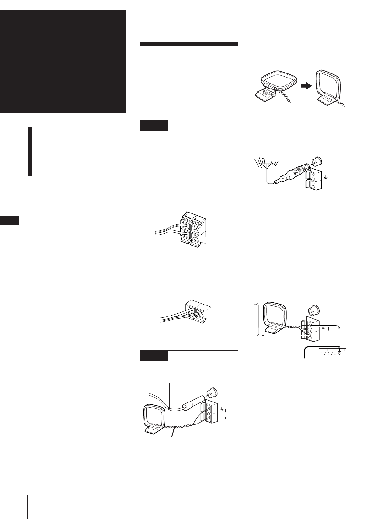
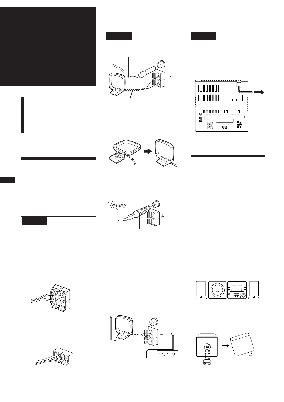
AM loop aerial connection
Connect the supplied loop aerial to the AM
and the y terminals.
To improve the FM reception
Connect an outdoor FM aerial to the FM
75Ω terminal, using a 75-ohm coaxial cable
and IEC standard socket connector.
IEC standard socket
connector
(not supplied)
To improve the AM reception
After you connect the AM aerial, connect a
6- to 15-meter (20- to 50- feet) insulated
wire to the AM terminal. Connect the y
terminal to earth.
Superwoofer
Connect the superwoofer to the WOOFER
connectors. Connect the grey cord with red
stripes to ‘ and the solid grey cord to ’.
’
‘
STEP 2 Connecting the
Aerials
FM lead aerial (supplied)*
FM
75Ω
AM
AM loop aerial (supplied)
* Note: Extend horizontally
Important
Ground the external aerial from y terminal
against lightning. To prevent a gas
explosion, do not connect the ground wire
to a gas pipe.
Insulated wires
(not supplied)
Ground wire
(not supplied)
Chapter 1: Setting up
Page 3
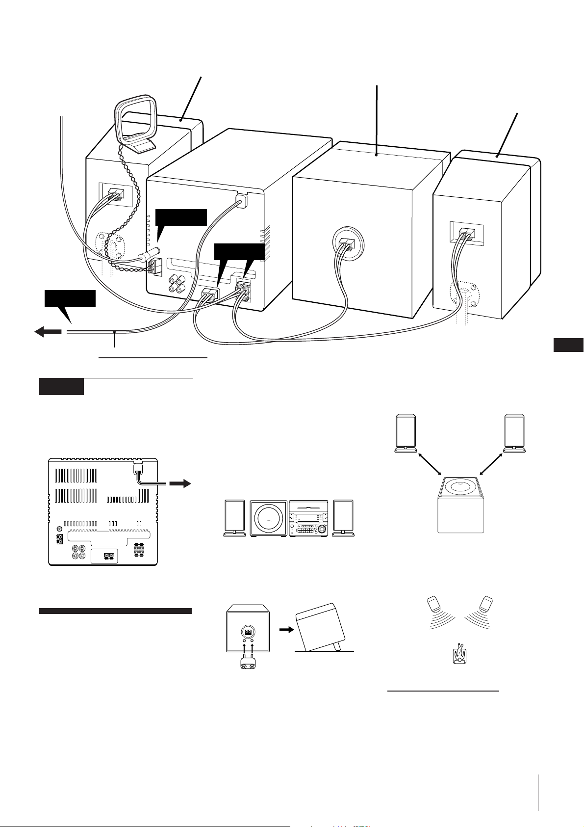
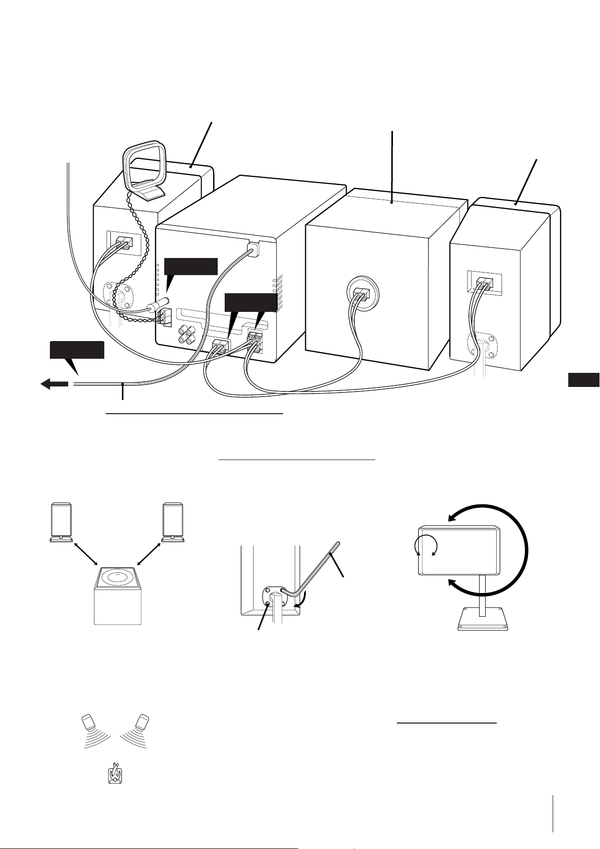
AM loop aerial
Right satellite speaker
Superwoofer
FM lead aerial
STEP 2
STEP 3
to a wall outlet
Do this connection last!
STEP 3 Connecting the
Power
Connect the mains lead to a wall outlet
after you have made all the above
connections.
STEP 1
Note
Do not install the woofer close to the unit,
and do not place the woofer above or
below the unit. Otherwise, the vibration
from the woofer may cause mechanical
noise or “skipping”.
When installing the speakers on
either side of the main unit
Place the superwoofer between the two
satellite speakers.
Left satellite speaker
GB
5
2 Install the superwoofer between the
satellite speakers with its front panel
facing upward.
to a wall
outlet
Installing the
Speakers
Proper speaker positioning is essential in
order to achieve directional effects and
diffused ambience.
When you install the speakers, refer to the
following instructions.
Once you have determined the final
placement, fasten the speakers to the
speaker stands.
+
=
When installing the satellite
speakers away the superwoofer
1 Insert the supplied stand into the rear of
the superwoofer.
When installing the satellite
speakers away from each other
Position the satellite speakers so they face
toward your listening position.
continue to next page ➔
Chapter 1: Setting up
Page 4
➔ continued
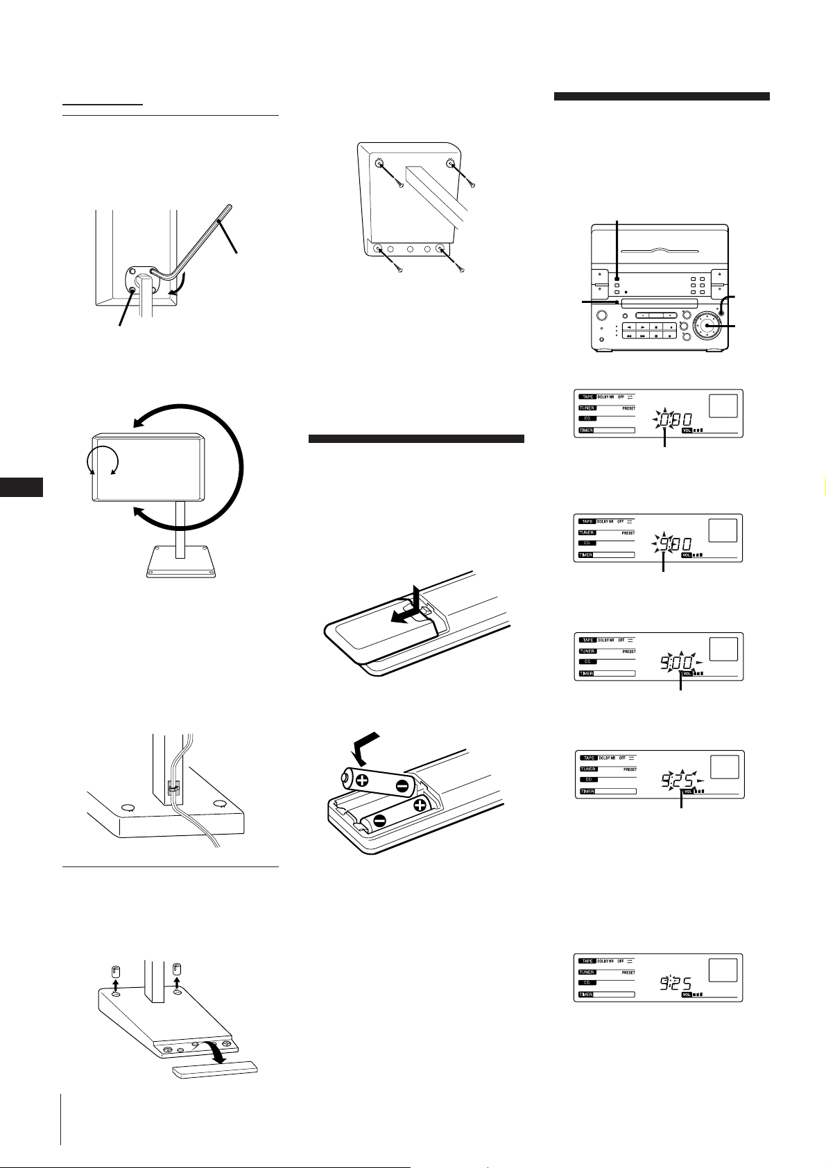
Fastening the speaker
stands
1 Fasten the four screws loosely using the
supplied wrench.
Wrench
Screw
2 Rotate the speaker to the desired
position.
You can also rotate the Sony logo.
2 Use a screw driver to attach the stands
to the wall with four wood screws (not
supplied).
3 Re-attach the caps and plates to the
speaker stands.
Note
Before attaching the speakers, check the
strength of the wall and the length of the
wood screws to prevent the speakers from
falling down.
Setting the Clock
The built-in clock shows the time in the
display. You need to set the clock to utilise
the timer-activated features of your stereo
system.
DISPLAY
3,5
+
=
2,4
1
1 Press CLOCK SET.
The hour indication begins flashing.
GB
S
6
3 Tighten the screws.
Note
Tighten the screws securely to prevent
mechanical noise.
To attach the cord holder to the
speaker stand
Peel off the sheets covering the cord
holders and attach the holders to the
speaker stands.
When attaching the
speakers to the wall
1 Detach the caps and plates from the
speaker stands.
Inserting the
Batteries
Insert two R6 (size AA) batteries in the
supplied remote for remote control.
1 Open the lid.
2 Insert two R6 (size AA) batteries.
Match the + and – indications to the
diagram in the battery compartment.
3 Close the lid.
Battery life
You can expect the remote to operate for
about six months (using Sony SUM-3 (NS)
batteries) before the batteries run down.
When the batteries no longer operate the
remote, replace both batteries with new
ones.
flashing
2 Set the current hour by turning the jog
dial until the correct hour appears.
flashing
3 Press ENTER/NEXT.
The minutes indication begins flashing.
flashing
4 Set the current minute by turning the jog
dial until the correct minute appears.
flashing
5 Press ENTER/NEXT.
The clock starts running and the upper
dot flashes. Use the time signal to set
the clock accurately.
The upper dot flashes for the first half of
a minute (0 to 29 seconds), and the
lower dot flashes for the last half of a
minute (30 to 59 seconds).
Chapter 1: Setting up
To avoid battery leakage
If you are not going to use the remote for a
long time, remove the batteries to avoid
damage caused by corrosion from battery
leakage.
To check the time while power is on
Press DISPLAY.
The current time appears for a few seconds.
To correct the clock setting
Repeat steps 1 to 5.
Page 5
For Your
Information
Precautions
Troubleshooting Guide
Maintenance
Specifications
Index to Parts and Controls
Index
Precautions
If you have any questions or problems
concerning your stereo system, please
consult your nearest Sony dealer.
On safety
•The unit is not disconnected from the AC
power source (mains) as long as it is
connected to the wall outlet, even if the
unit itself has been turned off.
•Unplug the system from the wall outlet
(mains) if it is not to be used for an
extended period of time. To disconnect
the cord (mains lead), pull it out by the
plug. Never pull the cord itself.
•Should any solid object or liquid fall into
the component, unplug the stereo system
and have the component checked by
qualified personnel before operating it
any further.
•The mains lead must be changed only at
the qualified service shop.
On installation
Place the stereo system in a location with
adequate ventilation to prevent heat buildup in the stereo system.
On condensation in the CD player
component
If the system is brought directly from a cold
to a warm location, or is placed in a very
damp room, moisture may condense on the
lens inside the CD player. Should this
occur, the CD player will not operate.
Remove the CD and leave the system
turned on for about an hour until the
moisture evaporates.
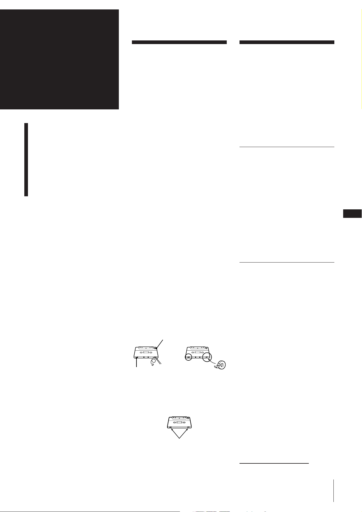
To save a tape permanently
To prevent a tape from being accidentally
recorded over, break off the cassette tab
from side A or B as illustrated. If you later
want to reuse the tape for recording, cover
the broken tab with adhesive tape.
Side A
Troubleshooting
Guide
If you run into any problem using the
stereo, use the following check list and first
check the following points:
• The mains lead is connected firmly.
• The speakers are connected correctly and
firmly.
Should any problem persist after you have
made the checks below, consult your
nearest Sony dealer.
Tuner
“STEREO” flashes in the display.
➔Adjust the aerial.
Severe hum or noise.
➔Adjust the aerial.
➔The signal strength is too weak.
Connect the external aerial.
➔Connect the ground wire.
A stereo FM programme cannot be
received in stereo.
➔Press STEREO/MONO so that
“STEREO” appears.
Tape Player
The tape does not record.
➔No tape in the tape compartment.
➔The tab has been removed from the
cassette.
➔The tape has reeled to the end.
The tape does not record nor
playback or there is a decrease in
sound level.
➔The heads are dirty. Clean them.
➔Magnetic deposits have built-up on
the record/playback head*.
GB
21
Tab of
side B
When you are using a type II (CrO2) tape,
be careful not to cover the detector slots
which allow the tape player to
automatically detect the type of tape.
Tab of side A
TYPE II
Detector slots
There is excessive wow or flutter, or
the sound drops out.
➔The capstans or pinch rollers are
contaminated*.
The tape does not erase completely.
➔Magnetic deposits have built-up on
the record/playback heads*.
Noise increases or the high
frequencies are erased.
➔Magnetic deposits have built-up on
the record/playback heads*.
* See “Maintenance.”
continue to next page ➔
For Your Information
Page 6
GB
22
➔ continued
CD Player
The disc tray does not close.
➔The CD is not placed correctly.
The CD will not play.
➔The CD is dirty.
➔The CD is inserted label side down.
➔The player is in pause mode.
➔Moisture condensation has builtup.
Leave the system turned on for
about an hour until the moisture
evaporates.
Play does not start from the first
track.
➔The CD player is in programme or
shuffle mode. Press PLAY MODE
repeatedly so that “PROGRAM” or
“SHUFFLE” disappears.
“ ” is displayed.
➔) on the unit was repeatedly
pressed at the end of the CD. Turn
the jog dial counterclockwise (or
press = on the remote) to return
to the normal display.
General
There is no sound.
➔Press VOLUME +.
➔The headphones are connected.
Disconnect them.
Sound comes from one channel or
unbalanced left and right volume.
➔Check the speaker connections of
the inoperative channel.
The left and right sound are
reversed.
➔Check the speaker connection and
speaker placement.
Bass is lacking or the location of the
musical instruments is apparently
imprecise.
➔Check the speaker connection for
proper phasing.
There is severe hum or noise.
➔TV or VCR is too close to the stereo
system. Move the stereo system
away from the TV or VCR.
“0:00” flashes in the display.
➔A power interruption occured.
Set the clock and timer settings
again.
The remote does not function.
➔The batteries have run down.
Replace both batteries.
➔There is an obstacle between the
remote and the system. Remove the
obstacle.
Restoring the Factory
Settings
Unplug the mains lead and then plug it
back into the wall outlet.
Keep DISPLAY and FUNCTION pressed
and press TAPE.
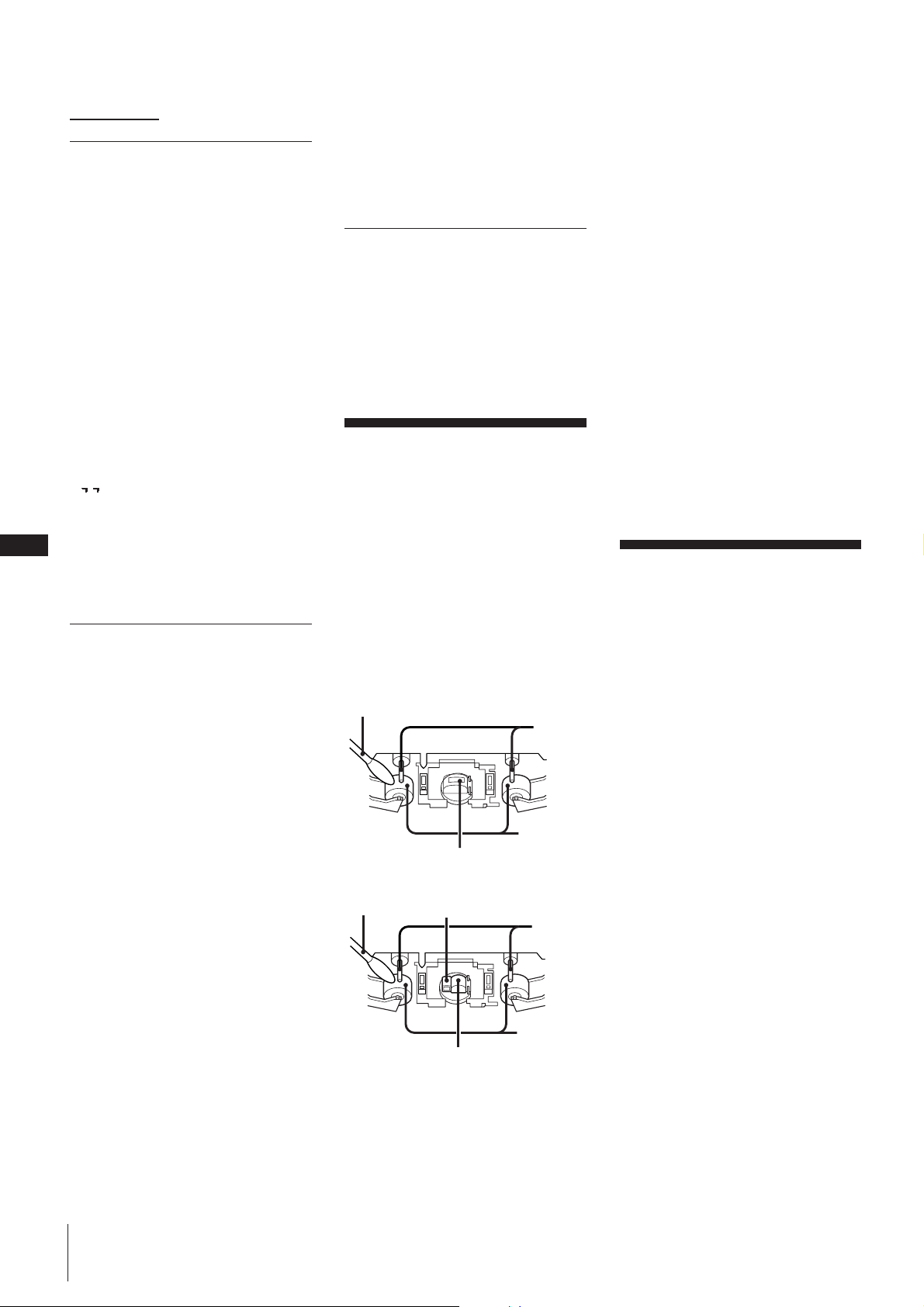
Maintenance
To clean the tape heads and tape
path
Contaminated tape heads cause poor
recording or sound drop-out in playback.
We recommend cleaning after every 10
hours of operation.
Open the tape compartment and wipe the
heads, the pinch rollers and the capstans
with a cleaning swab slightly moistened
with cleaning fluid or alcohol. Wipe the
parts shown below.
Deck A
Cleaning swab
Capstan
Pinch roller
Playback head
Deck B
Cleaning swab
Insert a tape when the areas cleaned are
completely dry.
Erase head
Capstan
Pinch roller
Record/playback head
To demagnetize the tape heads
After 20 to 30 hours of use, enough residual
magnetism will have built up on the heads
to begin to cause loss of high frequencies
and hiss. At this time, demagnetize the
heads and all metal parts in the tape path
with a commercially available tape head
demagnetizer. Refer to the instructions of
the demagnetizer.
To clean the cabinet
Use a soft cloth slightly moistened with
mild detergent solution.
To clean the CD
When a CD is dirty, clean it with a cleaning
cloth. Wipe the CD from the centre out.
Notes on CD
•Do not use solvents such as benzene,
thinner, commercially available cleaners,
or anti-static spray intended for vinyl LPs.
•If there is a scratch, dirt or fingerprints on
the CD, it may cause a tracking error.
Specifications
CD player section
System Compact disc digital audio
system
Laser Semiconductor laser (λ =
780 nm)
Emission duration:
continuous
Laser output Max 44.6 µW*
* This output is the value
measured at a distance of
200 mm from the
objective lens surface on
the Optical Pick-up Block
with 7 mm aperture.
Wavelength 780 – 790 nm
Frequency response
2 Hz – 20 kHz
Signal-to-noise ratio
More than 65 dB
Dynamic range
More than 97 dB
Tuner section
FM stereo, FM/AM superheterodyne tuner
FM tuner section
Tuning range 87.5 – 108.0 MHz (50 kHz
step)
Aerial FM lead aerial
Aerial terminals
75 ohm unbalanced
Intermediate frequency
10.7 MHz
For Your Information
Page 7
AM tuner section
Tuning range For Italian model:
AM: 522 – 1,611 kHz
For German model:
AM: 531 – 1,602 kHz
For other models:
MW: 531 – 1,602 kHz
LW: 153 – 279 kHz
Aerial AM loop aerial
External aerial terminals
Intermediate frequency
450 kHz
Tape player section
Recording system
4-track 2-channel stereo
Frequency response
(DOLBY NR OFF)
40 – 13,000 Hz (±3 dB),
using Sony TYPE I cassette
40 – 14,000 Hz (±3 dB),
using Sony TYPE II cassette
Wow and flutter
0.1% WRMS ±0.3% (DIN)
Superwoofer SS-W33D
Speaker system
Full range
Speaker units 13 cm dia., cone type
Enclosure type Bass reflex type
Rated impedance
6 ohms
Frequency response
40 – 180 Hz
Dimensions Approx. 225 × 210 ×
295 mm
7
(8
/8 × 8 1/4 × 11
5
/8 in.)
(w/h/d) incl. front grille
Mass Approx. 4.8 kg (10 lb 9 oz)
Supplied accessories
AM loop aerial (1)
Remote (1)
Sony SUM-3 (NS) batteries (2)
FM lead aerial (1)
Speaker cords (3)
Supporter (1)
Cord holders (2)
Wrench (1)
1 § EJECT DECK A button (12)
2 DECK A (12)
3 DISPLAY button (6, 7)
4 SLEEP button (18)
5 CD CYNCHRO button (13)
6 DOLBY NR button (12)
7 DIRECTION MODE button (12)
8 DECK B (13)
9 § EJECT DECK B button (13)
!º TIMER SELECT button (19)
!¡ CLOCK SET button (6)
!™ TIMER SET button (18)
!£ PLAY MODE button (8, 14)
!¢ REPEAT button (9)
!∞ HI-SPEED DUBBING button (15)
!§ § OPEN/CLOSE CD button (7)
!¶ !• !ª @º @¡ @™ @£
Amplifier section
DIN power output:
Satellite: 7 W + 7 W (4 ohms at
1 kHz, DIN)
Superwoofer: 30 W (6 ohms at
60 Hz, DIN)
Continuous RMS power output
Satellite: 10 W + 10 W (4 ohms at
1 kHz, 10% THD)
Superwoofer: 35 W (6 ohms at
60 Hz, 10% THD)
Music power output
Satellite: 15 W + 15 W (4 ohms at
1 kHz, 10% THD)
Superwoofer: 45 W (6 ohms at
60 Hz, 10% THD)
Inputs
MD IN: Sensitivity 450 mV,
impedance 47 kilohms
Outputs
MD OUT: Sensitivity 250 mV, 1 kΩ
PHONES (stereo phone jack):
accept headphones of
8 ohms or more.
Speaker section
Satellite speaker SS-S33D
Speaker system
Full range
Speaker units 6 cm dia., cone type
Enclosure type Closed type (with supplied
speaker stand)
Rated impedance
4 ohms
Frequency response
180 Hz – 20 kHz
Dimensions Approx. 110 × 185 ×
100 mm
5
(4
/16 × 7 5/16 × 3
15
/16 in.)
(w/h/d) (per speaker, incl.
front grille)
Approx. 120 × 130 mm (w/
d) (pedestal)
Mass Approx. 1.8 kg (3 lb 15 oz)
per speaker with speaker
stand
General
Power requirement
220 – 230 V AC, 50/60 Hz
Power consumption
85 W
Dimensions Approx. 225 × 210 ×
235 mm
7
(8
/8 × 8 3/8 × 9
3
/8 in.) (w/
h/d) incl. projecting parts
and controls
Mass Approx. 4.8 kg (10 lb 9 oz)
Design and specifications are subject to
change without notice.
Index to Parts and
Controls
Refer to the pages indicated in parentheses
for how to use the controls.
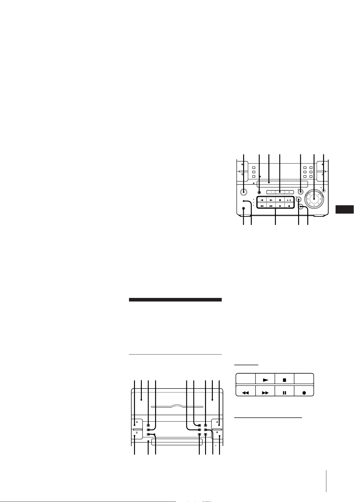
Front Panel
123 56 7 98
4
!¡ !™ !£!¢ !∞ !§!º
=
@¢
@∞
@§ @¶ @•
!¶ SYSTEM POWER ON/STANDBY
button (19)
!• FUNCTION button (13)
!ª Disc tray (7)
@º VOLUME +/– button (17)
@¡ TAPE button and lamp (12)
@™ Jog dial (6, 7, 10, 14, 18)
@£ ENTER/NEXT button (6, 8, 11, 14, 19)
@¢ PHONES jack (stereo phone jack) (17,
20)
@∞ WOOFER LEVEL button (17)
@§ Operating buttons* (7, 10, 12, 19)
@¶ TUNER/BAND button and lamp (10)
@• CD button and lamp (7)
∗ Operating buttons
The buttons you can operate for CD player,
tuner, or tape player light up.
CD player
REC
continue to next page ➔
For Your Information
+
GB
23
Page 8
➔ continued
Tuner
TUNING MODE TUNER MEMORY
STEREO/MONO
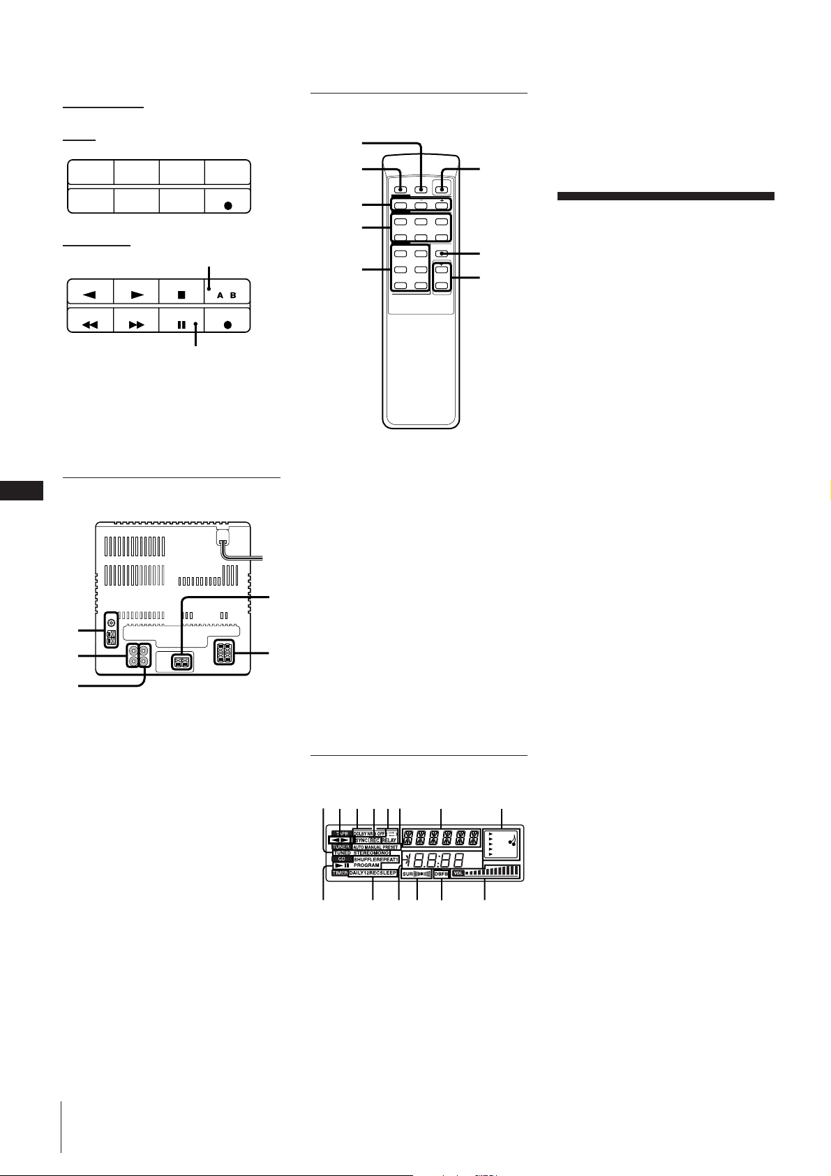
Remote
1
2
!™ SUR indication (17)
!£ DBFB indication (17)
!¢ VOLUME indication (17)
6
GB
24
REC
Tape player
A or B
DECK SELECT
REC
When you select
deck B, P lights up.
Note
A or B lights up when you operate CD
player or tuner. However, you can ignore
it.
Rear Panel
1
2
3
1 Aerial terminals (4)
2 MD OUT jacks (20)
3 MD IN jacks (20)
4 Woofer connectors (4)
5 Speaker connectors (4)
For Your Information
4
5
3
4
5
(
=
0
p
P
+
(9
)
p
7
8
1 SLEEP button
2 DBFB button (17)
3 Tuner operating buttons
BAND button
PRESET +/– button
4 CD operating buttons
( (play) button
P (pause) button
p (stop) button
=/+ button (7, 14)
EDIT button (13)
5 Tape operating buttons
9/( (reverse side/front side) play
buttons
p (stop) button
0/) buttons
DECK SELECT button
6 SYSTEM POWER switch
7 SELECT 1 – 5 button (17)
8 VOLUME +/– buttons
Display Window
1423 6 875
ROCK
POPS
JAZZ
CLASSIC
DANCE
STEP
dB
kHz
MIN
MHz
!™ !¢!
!¡90
1 Tuner indications (10)
2 Tape play indications (12)
3 DOLBY NR indication (12)
4 CD SYNCHRO indication (13)
5 Tape direction indications (12)
6 AUTO/MANUAL/PRESET indications
(10)
7 Function indications (6, 8, 10, 14, 19)
8 Audio emphasis indications (17)
9 CD play mode indications (7)
0 Timer indications (19)
!¡ Frequency/time indication (6, 10)
£
Index
Adjusting
the sound 17
Aerials 4
AMS 7
CD player 7
Clock setting 6
Connecting
optional equipment 20
the aerials 4
the power 5
the speakers 4
the stereo 4
DBFB 17
Dolby NR (noise reduction) 12
Dubbing 15
Headphones 17, 20
Inserting batteries 6
Installing the speakers 5
Maintenance 22
Normal play 7
One touch play 8, 10, 12
Optional equipment 20
Parts identification 23
Playing
a CD (normal play) 7
a tape 12
preset radio stations 11
tracks in random order (shuffle play)
8
tracks in the desired order
(programme play) 8
tracks repeatedly (repeat play) 9
Precautions 21
Programme play 8
Radio stations
presetting 11
tuning in 10
Recording
a CD 13
a radio programme 15
another tape (dubbing) 15
timer recording 19
Recording CDs
specifying tape length (time edit) 13
specifying track order (programme
edit) 14
Relay play 12
Repeat play 9
Selecting the audio emphasis 17
Shuffle play 8
Sound adjusting 17
Speakers 4
Tape player 12
Time edit 13
Timer
falling asleep to music 18
timer recording 19
waking up to music 18
Troubleshooting guide 21
Tuner 10
Woofer level 17
Page 9
Chapitre 1:
ETAPE 2 Connexion des
antennes
ETAPE 3 Connexion du
cordon secteur
Préparatifs
Connexion de la chaîne
Installation des enceintes
Mise en place des piles
Réglage de l’horloge
Connexion de la
chaîne
F
Référez-vous aux illustrations ci-dessous
4
pour raccorder la chaîne stéréo.
Si vous souhaitez raccorder des appareils
en option, reportez-vous à “Connexion
d’un appareil en option” au chapitre 6.
ETAPE 1 Connexion des
enceintes
Pour installer les enceintes, reportez-vous à
“Installation des enceintes”.
Enceintes satellites droite (R) et gauche
(L)
Raccordez l’enceinte droite aux connecteurs
R et l’enceinte gauche aux connecteurs L
avec les cordons gris rayés blanc branchés
sur ‘ et les cordons gris uni branchés sur
’.
‘
R
’
Caisson d’extrême grave
Raccordez le caisson d’extrême grave aux
connecteurs WOOFER avec le cordon gris
rayé rouge branché sur ‘ et le cordon gris
uni branché sur ’.
’
‘
‘
’
Antenne fil FM* (fournie)
FM
75Ω
AM
Antenne cadre AM (fournie)
*Remarque: Etendez-la
horizontalement.
Connexion de l’antenne cadre AM
Raccordez l’antenne cadre AM fournie aux
bornes AM et y.
Effectuez toutes les connexions décrites cidessus avant de brancher le cordon
d’alimentation secteur sur une prise
murale.
à une
prise
murale
Installation des
enceintes
Pour améliorer la réception FM
Raccordez une antenne FM extérieure à la
borne FM 75Ω avec un câble coaxial de
75 ohms et un connecteur femelle IEC.
FM
75Ω
AM
Connecteur femelle IEC
(non fourni)
Pour améliorer la réception AM
Après avoir raccordé l’antenne AM,
branchez un fil isolé de 6 à 15 mètres de
long sur la borne AM et reliez la borne y à
la terre.
Important
Par mesure de protection contre la foudre,
raccordez l’antenne extérieure à la borne y
de terre. Ne raccordez pas le fil de terre à
un tuyau de gaz afin d’éviter tout risque
L
d’explosion.
Fil isolé
(non fourni)
Fil de terre
(non fourni)
FM
75Ω
AM
Le bon positionnement des enceintes est
essentiel pour obtenir un effet directionnel
et une ambiance diffuse.
Quand vous installez les enceintes, référezvous aux instructions suivantes.
Quand vous avez déterminé l’emplacement
définitif des enceintes, fixez les enceintes
sur les pieds.
Remarque
Ne pas installer le caisson d’extrême grave
près de l’appareil, ni dessus ou dessous
l’appareil, sinon les vibrations du caisson
peuvent causer du bruit mécanique ou des
coupures de son.
Si vous installez les deux enceintes
des deux côtés de la chaîne
Mettez le caisson d’extrême grave entre les
deux enceintes satellites.
+
=
Si vous installez les enceintes
satellites à l’écart du caisson
d’extrême grave
1 Insérez le pied fourni à l’arrière du
caisson d’extrême grave.
Chapitre 1: Préparatifs
Page 10
S
Antenne cadre AM
Enceinte satellite droite
Caisson d’extrême grave
Antenne fil FM
ETAPE 3
STEP 3
à une prise
murale
ETAPE 2
STEP 2
ETAPE 1
STEP 1
Effectuez cette connexion en dernier!
Enceinte satellite gauche
F
5
2 Installez le caisson d’extrême grave
entre les deux enceintes satellites et avec
la façade tournée vers le haut.
Quand vous installez les deux
enceintes satellites à l’écart l’une de
l’autre
Positionnez les deux enceintes satellites de
sorte qu’elles soient tournées vers votre
position d’écoute.
Fixation des pieds
d’enceintes
1 Vissez les quatre vis sans forcer en
utilisant la clé fournie.
Clé
Vis
2 Faites pivoter l’enceinte pour la mettre à
la position souhaitée.
Vous pouvez aussi tourner le logo Sony.
3 Serrez les vis.
Remarque
Serrez les vis à fond pour éviter tout bruit
mécanique.
Voir page suivante ➔
Chapitre 1: Préparatifs
Page 11

➔ suite
Pour fixer les colliers aux pieds
d’enceinte
Décoller les feuilles qui protègent les
colliers et fixez les colliers aux pieds
d’enceintes.
Pour fixer les pieds au mur
1 Retirez les caches et plaques des pieds.
F
Mise en place des
piles
Mettez deux piles R6 (format AA) dans la
télécommande fournie pour le contrôle à
distance.
1 Ouvrez le couvercle.
2 Insérez deux piles R6 (format AA).
Faites correspondre les indications + et –
des piles avec celles du logement.
1 Appuyez sur CLOCK SET.
Les chiffres de l’heure se mettent à
clignoter.
clignotement
2 Tournez la molette jusqu’à ce que
l’heure correcte apparaisse.
clignotement
3 Appuyez sur ENTER/NEXT.
Les chiffres des minutes se mettent à
clignoter.
clignotement
4 Tournez la molette jusqu’à ce que les
minutes correctes apparaissent.
6
2 Utilisez un tournevis pour fixer les pieds
au mur avec quatre vis à bois (non
fournies).
3 Remettez les caches et les plaques sur les
pieds.
Remarque
Quand vous fixez les enceintes au mur,
vérifiez que le mur est assez solide et les vis
assez longues pour que les enceintes ne
tombent pas.
3 Fermez le couvercle.
Autonomie des piles
La télécommande fonctionne pendant
environ six mois avec des piles Sony SUM-3
(NS). Quand la télécommande ne
fonctionne plus, remplacez toutes les piles
par des neuves.
Pour éviter une fuite d’électrolyte
Si vous ne comptez pas utiliser la
télécommande pendant un certain temps,
enlevez les piles pour éviter tout dommage
dû à la corrosion après une fuite
d’électrolyte.
Réglage de l’horloge
L’horloge intégrée indique l’heure sur
l’affichage. Vous devez régler l’horloge
pour pouvoir utiliser les diverses fonctions
de programmation.
DISPLAY
clignotement
5 Appuyez sur ENTER/NEXT.
L’horloge se met en marche et le point
supérieur clignote. Aidez-vous d’un
signal de top horaire pour régler l’heure
précisément.
Le point supérieur clignote pendant la
première moitié d’une minute (0 à 29
secondes) tandis que le point inférieur
clignote pendant la seconde moitié
d’une minute (30 à 59 secondes).
Pour consulter l’heure quand la
chaîne est sous tension
Appuyez sur DISPLAY.
L’heure apparaît pendant quelques
secondes.
Pour rectifier l’heure
Répétez les étapes 1 à 5.
Chapitre 1: Préparatifs
1
3,5
+
=
2,4
Page 12

Informations
supplémentaires
Précautions
Guide de dépannage
Entretien
Spécifications
Nomenclature
Index
Précautions
Pour toute question ou difficulté
concernant la chaîne stéréo, veuillez
consulter le revendeur Sony le plus proche.
Sécurité
•La chaîne stéréo n’est pas déconnectée de
la source d’alimentation secteur tant
qu’elle est branchée sur la prise murale,
même si vous l’avez mise hors tension.
•Débranchez la chaîne de la prise secteur si
vous ne comptez pas l’utiliser pendant un
certain temps. Pour débrancher le cordon
secteur, tirez sur la fiche et non pas sur le
cordon.
•Si un solide ou un liquide pénétrait dans
la chaîne, débranchez– la et faites-la
vérifier par un technicien qualifié avant
de la réutiliser.
•Si vous devez changer le cordon
d’alimentation secteur, faites appel à un
professionnel uniquement.
Installation
Installez la chaîne dans un endroit bien
ventilé pour éviter une surchauffe interne.
Guide de dépannage
Si vous rencontrez des problèmes quand
vous utilisez la chaîne stéréo, consultez la
liste ci-dessus. Cependant, veuillez d’abord
vérifier les deux points suivants:
•Le cordon d’alimentation secteur doit être
branché à fond.
•Les enceintes doivent être raccordées
correctement.
Si vous ne parvenez pas à résoudre le
problème malgré les vérifications suivantes,
consultez votre revendeur Sony.
Tuner
“STEREO” clignote sur l’affichage.
➔Réglez l’antenne.
Bourdonnement ou parasites
importants.
➔Réglez l’antenne.
➔Le signal est trop faible.
Raccordez une antenne extérieure.
➔Raccordez le fil de terre.
Condensation d’humidité dans le
lecteur CD
Si vous transportez la chaîne directement
d’un endroit froid dans une pièce chaude,
ou si vous l’installez dans une pièce
humide, de l’humidité risque de se
condenser sur la lentille à l’intérieur du
lecteur CD. Dans ce cas, le lecteur CD ne
fonctionne pas. Enlevez le CD et laissez la
chaîne sous tension pendant environ une
heure jusqu’à ce que l’humidité se soit
évaporée.
Protection permanente d’une
cassette
Pour éviter d’effacer accidentellement
l’enregistrement d’une cassette, brisez
l’ergot de la face A ou B, comme indiqué
sur l’illustration. Si vous voulez
réenregistrer cette cassette par la suite,
recouvrez l’orifice d’un morceau de ruban
adhésif.
Face A
Ergot de
la face B
Si vous utilisez des cassettes de type II
(CrO2), faites attention de ne pas recouvrir
les fentes qui permettent au lecteur de
détecter le type de cassette.
Ergot de la
face A
TYPE II
Une émission FM stéréo ne peut pas
être reçue en stéréo.
➔Appuyez sur STEREO/MONO
pour que “STEREO” apparaisse.
Platine à cassettes
Impossible d’enregistrer sur une
cassette.
➔Il n’y a pas de cassette dans le
logement.
➔L’ergot de la cassette a été brisé.
➔La bande est finie.
Vous ne pouvez pas enregistrer ni
écouter une cassette, ou bien il y a
une baisse du niveau sonore.
➔Les têtes sont sales. Nettoyez-les.
➔Des résidus magnétiques se sont
accumulés sur les têtes
d’enregistrement/lecture.*
Pleurage ou scintillement excessif ou
perte de son.
➔Les cabestans ou les galets
presseurs sont encrassés.*
Vous ne parvenez pas à effacer
complètement une cassette.
➔Des résidus magnétiques se sont
accumulés sur les têtes
d’enregistrement/lecture.*
Augmentation de parasites ou
effacement des hautes fréquences.
➔Des résidus magnétiques se sont
accumulés sur les têtes
d’enregistrement/lecture.*
F
21
Fentes de détection
* : Voir “Entretien”.
Voir page suivante ➔
Informations supplémentaires
Page 13

➔ suite
Lecteur CD
Le plateau de disque ne s’ouvre pas.
➔Le CD n’est pas posé correctement.
La lecture du CD ne démarre pas.
➔Le CD est sale.
➔Le CD est à l’envers.
➔Le lecteur est en mode de pause.
➔De l’humidité s’est condensée.
Laissez la chaîne sous tension
pendant environ une heure jusqu’à
ce que l’humidité se soit évaporée.
La lecture ne commence pas par la
première plage.
➔Le lecteur est en mode de lecture
programmée ou aléatoire.
Appuyez de façon répétée sur
PLAY MODE jusqu’à ce que
“PROGRAM” ou “SHUFFLE”
disparaisse.
“ ” est affiché.
➔Vous avez appuyé plusieurs fois
sur ) de la chaîne à la fin du CD.
F
22
Tournez la molette vers la gauche
(ou appuyez sur = de la
télécommande) pour revenir à
l’affichage normal.
Généralités
Aucun son.
➔Appuyez sur VOLUME +.
➔Le casque est branché.
Débranchez-le.
Le son ne vient que d’un seul canal,
ou déséquilibre entre les canaux
gauche et droit.
➔Vérifiez les connexions du canal qui
ne fonctionne pas.
Les sources sonores gauche et droite
sont inversées.
➔Vérifiez les connexions d’enceintes
et l’emplacement des enceintes.
Faiblesse des graves ou localisation
des instruments imprécise.
➔Vérifiez si la phase des enceintes est
correcte.
La télécommande ne fonctionne pas.
➔Les piles sont épuisées. Remplacez
les deux piles.
➔Il y a un obstacle entre la
télécommande et la chaîne.
Enlevez l’obstacle.
Rétablissement des
réglages usine
Débranchez le cordon d’alimentation puis
rebranchez-le sur la prise secteur.
Appuyez sur TAPE tout en tenant
DISPLAY et FUNCTION enfoncées.
Entretien
Nettoyage des têtes et du passage
de la bande
Des têtes encrassées peuvent provoquer des
pertes de son à la lecture et réduire la
qualité de l’enregistrement. Il est
recommandé de nettoyer les têtes toutes les
10 heures de fonctionnement.
Ouvrez le compartiment de la cassette et
essuyez les têtes, les galets presseurs et les
cabestans avec un coton-tige légèrement
imprégné d’un liquide de nettoyage ou
d’alcool. Nettoyez les parties indiquées cidessous.
Platine A
Coton-tige
Cabestans
Galets presseurs
Tête de lecture
Platine B
Coton-tige
Tête d’effacement
Cabestans
Démagnétisation des têtes
Au bout de 20 à 30 heures de
fonctionnement, du magnétisme résiduel se
dépose sur les têtes et peut commencer à
provoquer des pertes de son dans les
hautes fréquences et un sifflement. Dans ce
cas, démagnétisez les têtes et les parties
métalliques du passage de la bande avec
une cassette de démagnétisation en vente
dans le commerce. Référez-vous au mode
d’emploi du démagnétiseur.
Nettoyage du coffret
Utilisez un chiffon doux légèrement
imprégné d’une solution détergente neutre.
Entretien des CD
Quand un CD est sale, essuyez-le avec un
chiffon de nettoyage. Essuyez le CD du
centre vers l’extérieur.
Remarques sur les CD
•N’utilisez pas de solvants, comme la
benzine, de diluant, de produits de
nettoyage vendus dans le commerce, ni de
vaporisateurs antistatiques destinés aux
disques en vinyle.
•Si le CD est rayé, sale ou couvert de traces
de doigts, il risque d’y avoir des erreurs
d’alignement.
Spécifications
Section lecteur CD
Système Système audionumérique
pour disques compacts
Laser Laser semi-conducteur
(λ = 780 nm)
Durée d’émission: continue
Sortie laser Max. 44,6 µW*
* Cette sortie est la valeur
mesurée à une distance de
200 mm de la surface de
l’objectif sur le bloc du
capteur optique pour une
ouverture de 7 mm.
Longueur d’ondes
780 – 790 nm
Réponse en fréquence
2 Hz – 20 kHz
Rapport signal sur bruit
Supérieur à 65 dB
Plage dynamique
Supérieure à 97 dB
Bourdonnement ou bruit.
➔Téléviseur ou magnétoscope à
proximité. Eloignez la chaîne de ces
appareils.
“0:00” clignote sur l’affichage.
➔Il y a eu une interruption
d’alimentation.
Réglez l’horloge et reprogrammez
la minuterie.
Informations supplémentaires
Galets presseurs
Tête d’enregistrement/lecture
Insérez une cassette quand les zones
nettoyées sont complètement sèches.
Section tuner
Système FM stéréo, tuner FM/AM
superhétérodyne
Section tuner FM
Plage d’accord 87,5 – 108,0 MHz (intervalle
de 50 kHz)
Antenne Antenne fil FM
Bornes d’antenne
75 ohms, asymétriques
Page 14

Fréquence intermédiaire
10,7 MHz
Section tuner AM
Plage d’accord
Modèle pour l’Italie
AM: 522 – 1.611 kHz
Modèle pour l’Allemagne
AM: 531 – 1.602 kHz
Autres modèles
PO: 531 – 1.602 kHz
GO: 153 – 279 kHz
Antenne Antenne cadre AM
Bornes d’antenne
extérieure
Fréquence intermédiaire
450 kHz
Section platine à cassettes
Système d’enregistrement
4 pistes, 2 canaux stéréo
Réponse en fréquence
(DOLBY NR hors service)
40 – 13.000 Hz (±3 dB), avec
cassette Sony de TYPE I
40 – 14.000 Hz (±3 dB), avec
cassette Sony de TYPE II
Pleurage et scintillement
0,1% efficace ±0,3% (DIN)
Dimensions Env. 110 × 185 × 100 mm
(l/h/p) (chaque enceinte,
avec grille avant)
Env. 120 x 130 mm (l/h/p)
(pied)
Poids Env. 1,8 kg enceinte et pied
Caisson d’extrême grave SS-W33D
Système d’enceinte
Pleine gamme
Haut-parleur 13 cm de dia., type à cône
Coffret Type basse-reflex
Impédance nominale
6 ohms
Réponse en fréquence
40 - 180 Hz
Dimensions Env. 225 x 210 x 295 mm
(l/h/p) avec grille avant
Poids Env. 4,8 kg
Accessoires fournis
Antenne cadre AM (1)
Télécommande (1)
Piles Sony SUM-3 (NS) (2)
Antenne fil FM (1)
Cordons d’enceintes (3)
Support (1)
Colliers (2)
Clé (1)
1 Touche d’éjection de la cassette A
(§ EJECT DECK A) (12)
2 Platine A (12)
3 Touche d’affichage (DISPLAY) (6, 7)
4 Touche de minuterie sommeil (SLEEP)
(18)
5 Touche d’enregistrement synchronisé de
CD (CD SYNCHRO) (13)
6 Touche de réduction de bruit (DOLBY
NR) (12)
7 Touche de mode de défilement
(DIRECTION MODE) (12)
8 Platine B (13)
9 Touche d’éjection de la cassette B
(§ EJECT DECK B) (13)
!º Touche de sélection de minuterie
(TIMER SELECT) (19)
!¡ Touche de réglage de l’horloge (CLOCK
SET) (6)
!™ Touche de mise en service de la
minuterie (TIMER SET) (18)
!£ Touche de mode de lecture (PLAY
MODE) (8, 14)
!¢ Touche de répétition (REPEAT) (9)
!∞ Touche de copie rapide (HI-SPEED
DUBBING) (16)
!§ Touche d’ouverture/fermeture du
plateau CD (§ OPEN/CLOSE CD) (7)
Section amplificateur
Puissance de sortie DIN:
Satellite: 7 W + 7 W (4 ohms à
1 kHz, DIN)
Extrême grave: 30 W (6 ohms à
60 Hz, DIN)
Puissance de sortie continue RMS:
Satellite: 10 W + 10 W (4 ohms à
1 kHz, 10% DHT)
Extrême grave: 35 W (6 ohms à
60 Hz, 10% DHT)
Puissance musicale
Satellite: 15 W + 15 W (4 ohms à
1 kHz, 10% DHT)
Extrême grave: 45 W (6 ohms à
60 Hz, 10% DHT)
Entrées
MD IN: Sensibilité 450 mV,
impédance de 47 kilohms
Sorties
MD OUT: Sensibilité 250 mV,
1 kilohm
PHONES (prise 6,35 stéréo):
accepte un casque de
8 ohms ou plus.
Section enceintes
Enceintes satellites SS-S33D
Système Pleine gamme
Haut-parleurs 6 cm diam., à cône
Caisson Type fermé (avec pied
fourni)
Impédance nominale
4 ohms
Réponse en fréquence
180 Hz - 20 kHz
Généralités
Alimentation Secteur 220 – 230 V,
50/60 Hz
Consommation
85 W
Dimensions hors tout
Env. 225 × 210 × 235 mm
(l/h/p)
Poids Env. 4,8 kg
La conception et les spécifications sont
modifiables sans préavis.
Nomenclature
Voir les pages entre parenthèses pour
utiliser les commandes.
Façade
123 56 7 98
4
!¶ !• !ª @º @¡ @™ @£
=
@¢
@∞
!¶ Interrupteur de mise sous tension de la
chaîne/veille (SYSTEM POWER ON/
STANDBY) (19)
!• Touche de fonction (FUNCTION) (13)
!ª Plateau de disque (7)
@º Touche de réglage du volume
(VOLUME +/–) (17)
@¡ Touche et témoin de cassette (TAPE)
(12)
@™ Molette de réglage/recherche (6, 7, 10,
14, 18)
@£ Touche de validation, étape suivante
(ENTER/NEXT) (6, 8, 11, 14, 19)
@¢ Prise de casque (PHONES) (prise 6,35
stéréo) (17, 20)
@∞ Touche de réglage du niveau d’extrême
grave (WOOFER LEVEL) (17)
@§ Touches d’exploitation* (7, 10, 12, 18)
@¶ Touche et témoin de radio/bande
(TUNER/BAND) (10)
@• Touche et témoin de CD (7)
@§ @¶ @•
F
23
+
Voir page suivante ➔
!¡ !™ !£!¢ !∞ !§!º
Informations supplémentaires
Page 15

➔ suite
STEP
kHz
dB
MHz
MIN
ROCK
POPS
JAZZ
CLASSIC
DANCE
!™ !¢!
£
!¡90
1423 6 875
∗Touches d’exploitation
Les touches que vous pouvez utiliser pour
faire fonctionner le lecteur CD, la radio ou
la platine à cassettes s’allument.
Télécommande
1
2
Affichage
6
Lecteur CD
Radio
TUNING MODE TUNER MEMORY
STEREO/MONO
Platine à cassettes
Quand vous sélectionnez la
F
Remarque
24
A ou B s’allume quand vous faites
platine B, P s’allume.
fonctionner le lecteur CD ou la radio. Mais
cette indication ne signifie rien.
Panneau arrière
1
2
3
A ou B
DECK SELECT
3
4
REC
5
(
=
0
p
P
+
(9
)
p
7
8
1 Indications de radio (TUNER) (10)
2 Indications de lecture (platine) (TAPE)
(12)
3 Indication de Dolby (DOLBY NR) (12)
4 Indication d’enregistrement synchronisé
de CD (CD SYNCHRO) (13)
REC
5 Indications de sens de défilement de la
bande (12)
6 Indication d’accord auto/manuel/
préréglé (AUTO/MANUAL/PRESET)
(10)
7 Indications de fonction (6, 8, 10, 14, 19)
8 Indications de l’effet sonore (17)
REC
2 Touche d’amplification des basses
(DBFB) (17)
3 Touches d’exploitation de la radio
Touche de bande (BAND)
Touches de préréglage (PRESET +/–)
4 Touches d’exploitation de CD
( Touche de lecture
1 Touche de minuterie sommeil (SLEEP)
9 Indications de mode de lecture de CD
(7)
!º Indications de la minuterie (19)
!¡ Indication de la fréquence/heure (6, 10)
!™ Indication de surround (SUR) (17)
!£ Indication d’amplification des basses
(DBFB) (17)
!¢ Indication de volume (VOLUME) (17)
P Touche de pause
p Touche d’arrêt
=/+ Touches de recherche
arrière/avant (7, 14)
Touche de montage (EDIT) (14)
5 Touches d’exploitation de la platine à
cassettes
9/( Touches de lecture de la face
avant/arrière
p Touche d’arrêt
0/) Touches de recherche arrière/
avant
4
Touche de sélection de platine (DECK
SELECT)
6 Interrupteur d’alimentation (SYSTEM
POWER)
7 Touche d’effets préréglés (SELECT 1 – 5)
5
(17)
8 Touche de réglage de volume
(VOLUME +/–)
1 Bornes d’antenne (4)
2 Prises de sortie auxiliaire (MD OUT) (20)
3 Prises d’entrée auxiliaire (MD IN) (20)
4 Connecteurs de caisson d’extrême grave
5 Connecteurs d’enceintes (4)
Informations supplémentaires
(4)
Page 16

Index
Antennes 4
AMS 7
Appareil en option 20
Connexion
au secteur 5
de la chaîne 4
des antennes 4
des enceintes 4
d’un appareil en option 20
Copie 15
Casque 17, 20
DBFB 17
Ecoute d’une station préréglée 11
Enceintes 4
Enregistrement
d’un CD 13
d’une autre cassette 15
d’une émission radio 15
programmé de la radio 19
Enregistrement de CD
Désignation de la durée de la bande
14
Désignation de l’ordre des plages 14
Enregistrement synchronisé de CD 12, 13,
14
Entretien 22
Fonction monotouche 8, 10, 13
Guide de dépannage 21
Installation des enceintes 4
Lecteur CD 7
Lecture
des plages dans un ordre donné
(lecture programmée) 8
des plages dans un ordre quelconque
(lecture aléatoire) 8
d’un CD (lecture normale) 7
d’une cassette 12
répétée des plages 9
Lecture à relais 12
Lecture aléatoire 8
Lecture normale 7
Lecture programmée 8
Lecture répétée 9
Minuterie
enregistrement programmé 19
pour s’endormir en musique 18
pour se réveiller en musique 18
Mise en place des piles 6
Montage horaire 14
Niveau du caisson d’extrême grave 17
Nomenclature 23
Platine à cassettes 12
Précautions 21
Radio 10
Réducteur de bruit Dolby 12
Réglage de l’horloge 6
Réglage du son 17
Sélection de l’effet sonore 17
Stations de radio
accord 10
préréglage 11
F
25
Informations supplémentaires
Page 17

Capítulo 1:
PASO 2 Conexión de las
antenas
PASO 3 Conexión de la
alimentación
Instalación
Conexión del sistema
estéreo
Instalación de los altavoces
Colocación de las pilas
Ajuste del reloj
Conexión del sistema
estéreo
E
Para conectar su sistema estéreo, utilice las
ilustraciones siguientes.
4
Si desea conectar componentes opcionales
al sistema estéreo, consulte “Conexión de
equipos opcionales” del Capítulo 6.
Antena monofilar de FM
(suministrada)*
FM
75Ω
AM
Antena de cuadro de AM (suministrada)
*Nota: Extiéndala horizontalmente.
Conexión de la antena de cuadro de
AM
Conecte la antena de cuadro suministrada a
los terminales AM y y.
Para mejorar la recepción de FM
Conecte una antena exterior de FM a los
terminales FM 75 Ω, utilizando un cable
coaxial de 75 ohmios con conector de
normas IEC.
FM
75Ω
Conecte el cable de alimentación a un
tomacorriente de CA después de haber
realizado todas las conexiones
anteriormente mencionadas.
a un
tomacorriente
de la red
Instalación de los
altavoces
La ubicación apropiada de los altavoces es
esencial para obtener efectos direccionales y
ambiente difundido.
Cuando instale los altavoces, refiérase a las
instrucciones siguientes.
Después de haber determinado la ubicación
final, fije los altavoces a los soportes de los
mismos.
PASO 1 Conexión de los
altavoces
Con respecto a la instalación de los
altavoces, consulte “Instalación de los
altavoces”.
Altavoces satélite derecho (R) e
izquierdo (L)
Conecte el altavoz derecho a los conectores
R y el izquierdo a los conectores L, con los
conductores raya blanca a ‘ y los grises a
’.
‘
R
‘
’
L
’
Altavoz de graves
Conecte el altavoz de graves a los
conectores WOOFER, con el conductor gris
con rayas rojas a ‘ y el conductor
completamente gris a ’.
’
‘
Capítulo 1: Instalación
AM
Conector de normas
(no suministrado)
Para mejorar la recepción de AM
Después de haber conectado la antena de
AM, conecte un conductor aislado de 6 a 15
metros al terminal AM. Conecte el terminal
y a tierra.
Importante
Conecte la antena exterior a tierra desde el
terminal y como medida de protección
contra rayos. Para evitar la explosión de
gas, no conecte el conductor de puesta a
tierra a un tubo de gas.
FM
75Ω
AM
Conductor aislado
(no suministrado)
Conductor de puesta a tierra
(no suministrado)
Nota
No instale el altavoz de graves cerca de la
unidad, ni lo coloque sobre ni debajo de la
unidad. De lo contrario, la vibración del
altavoz de graves podría causar ruido
mecánico o “salto de sonido”.
Cuando instale los altavoces en
cualquier lado de la unidad
Coloque el altavoz de supergraves entre los
dos altavoces satélite.
+
=
Cuando instale los altavoces satélite
alejado del altavoz de supergraves
1 Inserte el soporte suministrado en la
parte posterior del altavoz de graves.
Page 18

S
Antena
monofilar de FM
PASO 3
STEP 3
a un tomacorriente
de la red
Altavoz satélite derecho
Antena de cuadro de AM
PASO 2
STEP 2
PASO 1
STEP 1
¡Realice este conexión en último lugar!
Altavoz de supergraves
Altavoz satélite
izquierdo
E
2 Instale el altavoz de supergraves entre
los altavoces satélite con su panel frontal
encarado hacia arriba.
Cuando instale los altavoces satélite
alejados entre sí
Coloque los altavoces satélite de forma que
queden encarados hacia la posición de
escucha.
Fijación de los soportes de
los altavoces
1 Apriete suavemente los cuatro tornillos
utilizando la llave suministrada.
Llave
Tornillo
5
2 Gire el altavoz hasta la posición
deseada.
Usted también podrá el logotipo Sony.
3 Apriete firmemente los tornillos.
Nota
Apriete con seguridad los tornillos para
evitar el ruido mecánico.
continúa en la página siguiente ➔
Capítulo 1: Instalación
Page 19

➔ continuación
Para fijar el sujetacables al soporte
del altavoz
Despegue las láminas que cubren los
sujetacables y fije éstos a los soportes del
altavoz.
Colocación de las
pilas
Inserte dos pilas R6 (tamaño AA) en el
telemando suministrado para controlar el
sistema a distancia.
1 Abra la tapa.
1
Presione CLOCK SET.
La indicación de la hora comenzará a
parpadear.
parpadeando
2 Ajuste la hora actual girando el mando
de lanzadera hasta que aparezca la hora
correcta.
Para instalar los altavodes
en la pared
1 Quite las tapas y las placas de los
soportes de los altavoces.
E
6
2 Utilice un destornillador para fijar los
soportes a la pared con cuatro tornillos
para medera (no suministrados).
2 Inserte dos pilas R6 (tamaño AA).
Haga coincidir los polos + y – con el
diagrama del interior del
compartimiento de las pilas.
3 Cierre la tapa.
Duración de las pilas
Usted podrá esperar que el telemando
funcione durante unos seis meses
(utilizando pilas SUM-3 (NS) Sony) antes
de que se agoten las pilas. Cuando las pilas
no puedan alimentar más el telemando,
reemplácelas todas por otras nuevas.
Para evitar la fuga del electrólito de las
pilas
Cuando no vaya a utilizar el telemando
durante mucho tiempo, extráigale las pilas
a fin de evitar el daño que podría causar el
electrólito de las mismas en caso de
fugarse.
parpadeando
3 Presione ENTER/NEXT.
La indicación de los minutos comenzará
a parpadear.
parpadeando
4 Ajuste los minutos actuales girando el
mando de lanzadera hasta que
aparezcan los minutos correctos.
parpadeando
5 Presione ENTER/NEXT.
El reloj comenzará a funcionar y
parpadeará el punto superior. Utilice
una señal horaria para ajustar con
precisión el reloj.
El punto superior parpadeará durante la
primera mitad de un minuto (0 a 29
segundos), y el punto inferior lo hará
durante la última mitad del minuto (30 a
59 segundos).
3 Vuelva a instalar las tapas y las placas
en los soportes de los altavoces.
Nota
Antes de fijar los altavoces, compruebe la
resistencia de la pared y la longitud de los
tornillos para madera a fin de evitar que se
caigan los altavoces.
Capítulo 1: Instalación
Ajuste del reloj
El reloj incorporado mostrará la hora en el
visualizador. Para utilizar las funciones
activadas mediante el temporizador de su
sistema estéreo tendrá que ajustar el reloj.
DISPLAY
1
3,5
+
=
2,4
Para comprobar la hora mientras la
alimentación esté conectada
Presione DISPLAY.
La hora actual aparecerá durante algunos
segundos.
Para corregir la hora
Repita los pasos 1 a 5.
Page 20

Información
TYPE II
Precauciones
adicional
Precauciones
Guía para la solución de
problemas
Mantenimiento
Especificaciones
Índice de partes y controles
Índice alfabético
Si tiene alguna pregunta o problema en
relación con su sistema estéreo, póngase en
contacto con su proveedor Sony.
Seguridad
•El sistema estéreo no se desconectará de la
fuente de alimentación de CA (red)
mientras el cable del tal sistema esté
enchufado en un tomacorriente de la red,
incluso aunque ponga en OFF el
interruptor de alimentación del mismo.
•Cuando no vaya a utilizar el sistema
estéreo durante mucho tiempo,
desenchúfelo del tomacorriente de CA.
Para desenchufar el cable de alimentación,
tire del enchufe. No tire nunca del propio
cable.
•Si dentro de cualquier componente del
sistema entra un líquido o un objeto
sólido, desenchúfelo de la red y haga que
sea comprobado por personal cualificado.
•Cuando tenga que cambiar el cable de
alimentación de CA, solicite este servicio a
un taller de reparaciones cualificado
solamente.
Instalación
Coloque el sistema estéreo en un lugar
adecuadamente ventilado a fin de evitar su
recalentamiento interno.
Condensación de humedad en el
reproductor de discos compactos
Si traslada el sistema estéreo directamente
de un lugar frío a otro cálido, o si lo coloca
en una sala muy húmeda, es posible que se
condense humedad en el interior del
reproductor de discos compactos. Cuando
ocurra esto, el reproductor de discos
compactos no funcionará. Extraiga el disco
compacto y deje el sistema con la
alimentación conectada durante una hora
hasta que se evapore la humedad.
Para conservar permanentemente
una cinta
Para evitar el borrado accidental de una
cinta, rompa la lengüeta de la cara A o B,
como se muestra en la ilustración. Si desea
volver a grabar en esta cinta, cubra los
orificios de las lengüetas con cinta
adhesiva.
Cara A
Lengüeta
de la cara
B
Cuando esté utilizando cassettes de cinta
TYPE II (CrO2), tenga cuidado de no cubrir
las ranuras detectoras utilizadas por el deck
de cassettes para determinar el tipo de
cinta.
Lengüeta
de la cara A
Ranuras detectoras
Guía para la solución
de problemas
Si se presenta algún problema durante la
utilización de su sistema estéreo, utilice la
lista de comprobaciones siguiente.
Compruebe en primer lugar los puntos
siguientes.
•El cable de alimentación deberá estar
firmemente conectado.
•Los cables de los altavoces deberán estar
también firmemente conectados.
Si el problema persiste después de haber
realizado las comprobaciones siguientes,
consulte a su proveedor Sony.
Sintonizador
En el visualizador parpadea
“STEREO”.
➔Ajuste la antena.
Ruido o zumbido fuerte.
➔Ajuste la antena.
➔La señal es demasiado débil.
Conecte una antena exterior.
➔Conecte un conductor de puesta a
tierra.
No es posible recibir un programa de
FM en estéreo.
➔Presione STEREO/MONO de
forma que aparezca “STEREO”.
Decks de cassettes
No es posible grabar una cinta.
➔No hay cassette en el
compartimiento del mismo.
➔El cassette carece de lengüetas de
seguridad.
➔La cinta está bobinada hasta el
final.
continúa en la página siguiente ➔
E
21
Información adicional
Page 21

➔ continuación
La cinta no se graba o no se
reproduce, o el nivel de sonido se
reduce.
➔Las cabezas están sucias.
Límpielas.
➔En las cabezas grabadora/
reproductoras se han acumulado
residuos magnéticos*.
Fluctuación y trémolo excesivos, o
pérdida de sonido
➔Los ejes de arrastre o los rodillos
compresores están contaminados*.
La cinta no se borra completamente.
➔En las cabezas grabadora/
reproductoras se han acumulado
residuos magnéticos*.
El ruido aumenta, o las altas
frecuencias se borran.
➔En las cabezas grabadora/
reproductoras se han acumulado
residuos magnéticos*.
* Consulte “Mantenimiento”.
Reproductor de discos
E
compactos
22
La bandeja del disco compacto no se
cierra.
➔El disco compacto no está
correctamente colocado.
El disco compacto no se reproduce.
➔El disco compacto está sucio.
➔El disco compacto está insertado al
revés.
➔El reproductor de discos compactos
está en el modo de pausa.
➔Se ha producido condensación de
humedad. Deje el sistema con la
alimentación conectada durante
aproximadamente una hora hasta
que la humedad se haya
evaporado.
La reproducción no se inicia desde la
primera canción.
➔El reproductor de discos compactos
se encuentra en el modo de
reproducción programada o
aleatoria. Presione repetidamente
PLAY MODE de forma que
desaparezca “PROGRAM” o
“SHUFFLE”.
Está visualizándose “ ”.
➔Ha presionado repetidamente )
al final de un disco compacto. Para
volver a la visualización normal,
gire el mando de lanzadera hacia la
izquierda (o presione = del
telemando).
Información adicional
Sección general
No hay sonido.
➔Presione VOLUME +.
➔Los auriculares están conectados.
Desconéctelos.
Solamente sale sonido a través de un
canal, o el volumen entre los canales
izquierdo y derecho está
desequilibrado.
➔Compruebe la conexión del altavoz
del canal inoperativo.
El sonido de los canales izquierdo y
derecho está invertido.
➔Compruebe la conexión y la
ubicación de los altavoces.
Carencia de graves o la ubicación de
los instrumentos musicales es
aparentemente imprecisa.
➔Compruebe si los altavoces están
conectados con la fase apropiada.
Zumbido o ruido considerable
➔Hay un televisor o una
videograbadora demasiado cerca
del sistema estéreo. Aleje el sistema
estéreo del televisor o de la
videograbadora.
En el visualizador parpadea “0:00”.
➔Se ha producido una interrupción
del suministro eléctrico. Vuelva a
ajustar el reloj y a programar el
temporizador.
El telemando no funciona.
➔Las pilas están agotadas.
Reemplace ambas.
➔Entre el telemando y el sistema
estéreo existe un obstáculo.
Elimínelo.
Restablecimiento de los
ajustes de fábrica
Desenchufe el cable de alimentación del
tomacorriente y vuelva a enchufarlo.
Mantenga pulsadas DISPLAY y
FUNCTION, y presione TAPE.
Mantenimiento
Para limpiar de las cabezas y de la
vía de paso de la cinta
Las cabezas de la cinta contaminadas
provocan la mala grabación o la pérdida de
sonido durante la reproducción. Se
recomienda limpiarlas cada 10 horas de
utilización.
Abra el compartimiento del cassette y frote
las cabezas, los rodillos compresores, y los
ejes de arrastre con un palillo de cabeza de
algodón ligeramente humedecido en
líquido limpiador o en alcohol. Frote las
partes mostradas a continuación.
Deck A
Palillo de cabeza de
algodón
Eje de
arrastre
Rodillo
compresor
Cabeza reproductora
Deck B
Palillo de
cabeza de
algodón
No inserte un cassette hasta que se hayan
secado las partes limpiadas.
Para desmagnetizar las cabezas de la
cinta
Después de 20 a 30 horas de utilización, es
posible que se haya acumulado
magnetismo residual suficiente como para
provocar la pérdida de altas frecuencias y
siseo. En tal caso, desmagnetice las cabezas
y todas las partes metálicas por las que pase
la cinta con un desmagnetizador adquirido
en una tienda del rano. Consulte el manual
de instrucciones del desmagnetizador.
Para limpiar la caja
Utilice un paño suave ligeramente
humedecido en una solución muy diluida
de detergente.
Para limpiar los discos compactos
Cuando se ensucie un disco compacto,
frótelo con un paño limpiador. Hágalo del
centro hacia los bordes.
Notas sobre los discos compactos
•No utilice disolventes tales como benceno,
diluidor de pintura, ni limpiadores ni
pulverizadores antiestáticos destinados a
discos analógicos.
•Si existen rayas, suciedad, o huellas
dactilares en un disco compacto, es
posible que se produzca un error de
seguimiento.
Cabeza
borradora
Cabeza grabadora/
reproductora
Eje de
arrastre
Rodillo
compresor
Page 22

Especificaciones
Sección del reproductor de discos
compactos
Sistema Audiodigital de discos
compactos
Láser De semiconductor (λ = 780
nm)
Duración de la emisión:
continua
Salida de láser 44,6 µW* como máx.
* Esta salida es el valor
medido a una distancia de
200 mm de la superficie
del objetivo del bloque
captor óptico con una
apertura de 7 mm.
Longitud de onda
780 – 790 nm
Respuesta en frecuencia
2 Hz – 20 kHz
Relación señal-ruido
Más de 65 dB
Gama dinámica
Más de 97 dB
Sección del sintonizador
Sintonizador superheterodino de FM
estéreo, FM/AM
Sección del sintonizador de FM
Gama de sintonía
87,5 – 108,0 MHz (intervalo
de 50 kHz)
Antena Monofilar de FM
Terminales de antena
75 ohmios, desequilibrados
Frecuencia intermedia
10,7 MHz
Sección del sintonizador de AM
Gama de sintonía
Modelo para Italia:
AM: 522 – 1.611 kHz
Modelo para Alemania:
AM: 531 – 1.602 kHz
Otros modelos:
MW: 531 – 1.602 kHz
LW: 153 – 279 kHz
Antena De cuadro de AM,
terminales para antena
exterior
Frecuencia intermedia
450 kHz
Sección de los decks de cassettes
Sistema de grabación
4 pistas, 2 canales, estéreo
Respuesta en frecuencia
(DOLBY NR en OFF)
40 – 13.000 Hz (±3 dB),
utilizando cassettes TYPE I
Sony)
40 – 14.000 (±3 dB),
utilizando cassettes TYPE II
Sony)
Fluctuación y trémolo
0,1 %, ponderación eficaz,
±0,3 % (DIN)
Sección del amplificador
Salida de potencia DIN
Satélite: 7 W + 7 W (4 ohmios a
1 kHz, DIN)
Supergraves: 30 W (6 ohmios a 60 Hz,
DIN)
Salida de potencia eficaz continua
Satélite: 10 W + 10 W (4 ohmios a 1
kHz, 10% de distorsión
armónica total)
Supergraves: 35 W (6 ohmios a 60 Hz,
10% de distorsión armónica
total)
Salida de potencia musical de pico
Satélite: 15 W + 15 W (4 ohmios a 1
kHz, 10% de distorsión
armónica total)
Supergraves: 45 W (6 ohmios a 60 Hz,
10% de distorsión armónica
total)
Entrada
MD IN Sensibilidad de 450 mV,
impedancia de 47
kiloohmios
Salidas
MD OUT Sensibilidad de 250 mV,
1 kΩ
PHONES (toma telefónica estéreo):
Acepta auriculares de 8 o
más ohmios.
Sección de los altavoces
Altavoces satélite SS-S33D
Sistema de altavoces
Gama completa
Unidades altavoces
6 cm de diá., tipo cono
Tipo de caja acústica
Tipo cerrado (con soportes
para altavoces
suministrados)
Impedancia nominal
4 ohmios
Respuesta en frecuencia
180 Hz - 20 kHz
Dimensiones Aprox. 110 x 185 x 100 (an/
al/prf) (por altaveoz,
incluyendo la rejilla frontal)
Aprox. 120 x 130 mm (an x
prf) (pedestal)
Masa Aprox. 1,8 kg por altavoz
con el soporte para altavoz
Altavoz de supergraves SS-W33D
Sistema de altavoces
Gama completa
Unidades altavoces
13 cm de diá., tipo cono
Tipo de caja acústica
Reflectora de graves
Impedancia nominal
6 ohmios
Respuesta en frecuencia
40 - 180 Hz
Dimensiones Aprox. 225 x 210 x 295 (an/
al/prf) incluyendo la rejilla
frontal
Masa Aprox. 4,8 kg
Accesorios suministrados
Antena de cuadro de AM (1)
Telemando (1)
Pilas SUM-3 (NS) Sony (2)
Antena monofilar de FM (1)
Cables para altavoces (3)
Soporte (1)
Sujetacables (2)
Llave (1)
Generales
Alimentación 220 – 230 V CA, 50/60 Hz
Consumo 85 W
Dimensiones Aprox. 225 x 210 x 235 mm
(an/al/prf), incluyendo
partes y controles salientes
Masa Aprox. 4,8 kg
Diseño y especificaciones sujetos a cambio
sin previo aviso.
Índice de partes y
controles
Con respecto a los detalles sobre cómo
utilizar los controles, consulte las páginas
indicadas entre paréntesis.
Panel frontal
123 56 7 98
1 Tecla de expulsión del deck A (§ EJECT
2 Deck A (DECK A) (12)
3 Tecla selectora de visualización
4 Tecla del cronodesconectador (SLEEP)
5 Tecla de grabación sincronizada con un
6 Tecla del sistema reductor de ruido
7 Tecla selectora de modo de sentido de
8 Deck B (DECK B) (13)
continúa en la página siguiente ➔
4
!¡ !™ !£!¢ !∞ !§!º
DECK A) (12)
(DISPLAY) (6, 8)
(18)
disco compacto (CD SYNCHRO) (13)
Dolby (DOLBY NR) (12)
movimiento de la cinta (DIRECTION
MODE) (12)
E
23
Información adicional
Page 23

➔ continuación
9 Tecla de expulsión del deck B (§ EJECT
DECK B) (13)
!º Tecla selectora de temporizador (TIMER
SELECT) (19)
!¡ Tecla de ajuste del reloj (CLOCK SET)
(6)
!™ Tecla de programación del
temporizador (TIMER SET) (18)
!£ Tecla selectora de modo de
reproducción (PLAY MODE) (8, 14)
!¢ Tecla de reproducción repetida
(REPEAT) (9)
!∞ Tecla de duplicación a gran velocidad
(HI-SPEED DUBBING) (16)
!§ Tecla de apertura/cierre de la bandeja
del disco compacto (§ OPEN/CLOSE
CD) (7)
Reproductor de discos compactos
REC
Sintonizador
TUNING MODE TUNER MEMORY
Decks de cassettes
STEREO/MONO
REC
A o B
DECK SELECT
REC
Telemando
1
2
3
4
5
6
(
=
0
p
P
+
(9
)
p
7
8
!¶ !• !ª @º @¡ @™ @£
E
24
@¢
@∞
!¶ Interruptor de alimentación del sistema
(SYSTEM POWER ON/STANDBY) (19)
!• Tecla selectora de función (FUNCTION)
(13)
!ª Bandeja del disco compacto (7)
@º Tecla de volumen (VOLUME +/–) (17)
@¡ Tecla y lámpara indicadora de cinta
(TAPE) (12)
@™ Mando de lanzadera (6, 7, 11, 14, 18)
@£ Tecla de introducción/paso siguiente
(ENTER/NEXT) (6, 8, 11, 15, 19)
@¢ Toma para auriculares (PHONES) (toma
telefónica estéreo) (17, 20)
@∞ Tecla de nivel del altavoz de graves
(WOOFER LEVEL) (17)
@§ Teclas de operación (7, 10, 12, 19)*
@¶ Tecla y lámpara indicadora de
sintonizador/banda (TUNER/BAND)
(10)
@• Tecla y lámpara indicadora de disco
compacto (CD) (7)
@§ @¶ @•
Cuando seleccione el deck B,
se encenderá P.
Nota
A o B se encenderá cuando controle el
reproductor de discos compactos o el
sintonizador. Sin embargo, usted podrá
+
=
ignorar esto.
1 Tecla del cronodesconectador (SLEEP)
2 Tecla de retroalimentación dinámica de
graves (DBFB) (17)
3 Teclas de operación del sintonizador
Tecla selectora de banda (BAND)
Tecla de memorización (PRESET +/–)
4 Teclas de operación del reproductor de
discos compactos
Panel posterior
Tecla de reproducción (()
Tecla de pausa (P)
Tecla de parada (p)
Teclas de retroceso/avance rápido
(=/+) (7, 14)
Tecla de edición (EDIT) (14)
5 Teclas de operación de los decks de
cassettes
Tecla de reproducción de la cara
posterior/frontal (9/()
Tecla de parada (p)
Teclas de rebobinado/avance rápido
(0/))
Tecla selectora de deck (DECK SELECT)
6 Interruptor de alimentación del sistema
(SYSTEM POWER)
7 Tecla de selección de énfasis de sonido
(SELECT 1-5) (17)
8 Teclas de volumen (VOLUME +/–)
1
2
3
1 Terminales para antena (4)
2 Tomas de salida para deck de
minidiscos (MD OUT) (20)
3 Tomas de entrada para deck de
4
5
minidiscos (MD IN) (20)
4 Conectores para el altavoz de graves
(WOOFER) (4)
5 Conectores para altavoces (4)
* Teclas de operación
Las teclas que podrá utilizar para
controlar el reproductor de discos
compactos, el sintonizador, y los decks de
cassettes se encenderán.
Información adicional
Page 24

Visualizador
1423 6 875
ROCK
POPS
JAZZ
CLASSIC
DANCE
STEP
dB
kHz
MIN
MHz
!™ !¢!
!¡90
1 Indicaciones del sintonizador (10)
2 Indicaciones de reproducción de cintas
(12)
3 Indicación del sistema de reducción de
ruido Dolby (DOLBY NR) (12)
4 Indicación de grabación sincronizada
con un disco compacto (CD SYNCHRO)
(13)
5 Indicaciones de sentido de movimiento
de la cinta (12)
6 Indicaciones de sintonía automática/
manual/memorizada (AUTO/
MANUAL/PRESET) (10)
7 Indicaciones de función (6, 8, 10, 14, 19)
8 Indicaciones de énfasis del sonido (17)
9 Indicaciones de modo de reproducción
de disco compacto (7)
!º Indicaciones del temporizador (19)
!¡ Indicación de frecuencia/hora (6, 10)
!™ Indicación de efecto perimétrico (SUR)
(17)
!£ Indicación de retroalimentación
dinámica de graves (DBFB) (17)
!¢ Indicación de volumen (VOLUME) (17)
£
Índice alfabético
Ajuste
del sonido 17
Ajuste del reloj 6
Ajuste del sonido 17
Altavoces 4
AMS (sensor automático de canciones) 7
Antenas 4
Auriculares 17, 20
Colocación de las pilas 6
Conexión
de antenas 4
de equipos opcionales 20
de la alimentación 5
de los altavoces 4
del sistema estéreo 4
DBFB (retroalimentación dinámica de
graves) 17
Decks de cassettes 12
Duplicación 15
Edición por tiempo 14
Emisoras
memorización 11
sintonía 10
Equipos opcionales 20
Grabación
con el temporizador 19
de la radio 15
de otra cinta (duplicación) 15
de un disco compacto 13
Grabación de discos compactos
especificando el orden de las
canciones (edición programada) 14
especificando la duración de la cinta
(edición por tiempo) 14
Guía para la solución de problemas 21
Índice de partes y controles 23
Instalación de los altavoces 4
Mantenimiento 22
Nivel del altavoz de graves 17
Precauciones 21
Reducción de ruido (NR) Dolby 12
Reproducción
con repetición de canciones
(reproducción repetida) 9
de canciones en el orden deseado
(reproducción programada) 8
de canciones en orden arbitrario
(reproducción aleatoria) 8
de un disco compacto (reproducción
normal) 7
de una cinta 12
Reproducción aleatoria 8
Reproducción con relevo 12
Reproducción normal 7
Reproducción presionando una sola tecla
8, 10, 12
Reproducción programada 8
Reproducción repetida 9
Reproductor de discos compactos 7
Selección del énfasis del sonido 17
Sintonía de emisoras memorizadas 11
Sintonizador 10
Temporizador
grabación con él 19
para despertarse con música 18
para dormirse con música 18
E
25
Información adicional
Page 25

Secção 1:
Preparativos
Ligação do sistema estéreo
Instalação dos altifalantes
PASSO 2 Ligação das
antenas
Antena filiforme FM (fornecida)*
FM
75Ω
AM
Antena de quadro AM (fornecida)
* Nota: Estire-a horizontalmente.
PASSO 3 Ligação da
alimentação
Ligue o cabo de alimentação CA a uma
tomada da rede somente após ter efectuado
todas as ligações acima.
a uma
tomada
da rede
Inserção de pilhas
Acerto do relógio
Ligação do sistema
estéreo
Utilize as ilustrações abaixo para ligar o seu
sistema estéreo.
Caso queira ligar algum componente
opcional ao sistema estéreo, consulte
“Ligação de equipamentos opcionais“ na
P
secção 6.
4
PASSO 1 Ligação das
colunas de altifalantes
Para a instalação das colunas de
altifalantes, consulte «Instalação dos
altifalantes».
Colunas de altifalantes satélites direita
(R) e esquerda (L)
Ligue a coluna direita aos conectores R, e a
coluna esquerda, aos conectores L. Ligue os
fios cinza com listras brancas fios cinza
correspondendo a ‘, e os fios cinza, a ’.
‘
R
’
Superaltifalante de graves
Ligue o superaltifalante de graves aos
conectores WOOFER. Ligue o fio cinza com
listras vermelhas a ‘, e o fio cinza, a ’.
’
‘
‘
’
Ligação da antena de quadro AM
Ligue a antena de quadro AM fornecida aos
terminais AM e y.
Instalação dos
altifalantes
Para aprimorar a recepção de FM
Ligue uma antena FM externa ao terminal
FM 75 Ω, mediante a utilização de um cabo
coaxial de 75 ohms e um conector de
tomada padrão IEC.
FM
75Ω
AM
Conector de tomada
padrão IEC (venda avulsa)
Para aprimorar a recepção de AM
Após efectuar a ligação da antena AM,
ligue um fio isolado de 6 a 15 metros ao
terminal AM. Efectue a ligação terra do
terminal y.
Importante
Efectue a ligação terra da antena externa do
terminal y como protecção contra
relâmpagos. Para evitar explosões de gás,
não ligue o fio terra a uma tubulação de
gás.
L
FM
75Ω
AM
Fios isolados
(venda avulsa)
Fio terra (venda
avulsa)
O posicionamento apropriado das colunas é
essencial para que se obtenham efeitos
direccionais e difusão ambiental.
Ao instalar as colunas de altifalantes,
consulte as instruções a seguir.
Uma vez que tenha determinado a
localização final, fixe as colunas aos
suportes de altifalante.
Nota
Não instale o altifalante de graves próximo
ao aparelho, tampouco coloque o altifalante
de graves sobre ou sob o aparelho. Do
contrário, as vibraçòes do altifalante de
graves podem causar ruídos mecânicos ou
«saltos».
Na instalação das colunas nas
laterais do aparelho principal
Coloque o superaltifalante de graves entre
as duas colunas satélites.
+
=
Na instalação das colunas satélites
distantes do superaltifalante de
graves
1 Insira o suporte fornecido na parte
posterior do superaltifalante de graves.
Secção 1: Preparativos
Page 26

Antena de quadro AM
S
Coluna satélite direita
Superaltifalante de graves
Antena filiforme FM
PASSO 3
STEP 3
a uma tomada
da rede
PASSO 2
STEP 2
PASSO 1
STEP 1
¡Efectue esta ligação por último!
Coluna satélite esquerda
P
2 Instale o superaltifalante de graves entre
as colunas satélites com o seu painel
frontal voltado para cima.
Na instalação das colunas satélites
distantes uma da outra
Posicione as colunas satélites de forma que
fiquem voltadas para a sua posição de
audição.
Fixação dos suportes de
altifalante
1 Aperte os quatro parafusos
frouxamente, usando a chave inglesa
fornecida.
Chave inglesa
Parafuso
5
2 Gire o altifalante até a posição desejada.
Pode-se também girar o logotipo Sony.
3 Aperte os parafusos.
Nota
Aperte os parafusos firmemente, para
evitar ruídos mecânicos.
Continua na próxima página ➔
Secção 1: Preparativos
Page 27

➔ Continuação
Para encaixar o prendedor de fio no
suporte de altifalante
Descasque as camadas de cobertura dos
prendedores de fio e encaixe os
prendedores aos suportes de altifalante.
Inserção de pilhas
Insira duas pilhas R6 (tamanho AA) no
telecomando fornecido para o controlo à
distância.
1 Abra a tampa.
1 Carregue em CLOCK SET.
A indicação da hora passa a piscar.
Pisca
2 Ajuste os dígitos da hora mediante o
girar do anel de avanço/retrocesso, até
que a hora corrente apareça.
Para encaixar as colunas
na parede
1 Retire as capas e placas dos suportes de
altifalante.
P
2 Utilize uma chave de fenda para
6
encaixar os suportes na parede com
quatro parafusos de madeira (venda
avulsa).
2 Insira duas pilhas R6 (tamanho AA).
Observe a correspondência dos pólos +
e – com o diagrama de polaridade no
compartimento de pilhas.
3 Feche a tampa.
Duração das pilhas
Avalia-se que o telecomando funcionará
por cerca de seis meses (com pilhas Sony
SUM-3(NS)) antes que as pilhas se
exauram. Quando as pilhas não mais
alimentarem o telecomando, substitua
ambas as pilhas por outras novas.
Prevenção contra a fuga de electrólito das
pilhas
Caso não pretenda utilizar o telecomando
durante um longo intervalo, retire as pilhas
para evitar avarias decorrentes de corrosão
por fuga de electrólito das pilhas.
Pisca
3 Pressione ENTER/NEXT.
A indicação dos minutos passa a piscar.
Pisca
4 Ajuste os dígitos dos minutos mediante
o girar do anel de avanço/retrocesso, até
que os minutos correntes apareçam.
Pisca
5 Carregue em ENTER/NEXT.
O relógio passa a funcionar e o ponto
superior dos dois pontos passa a piscar.
Utilize um sinal da hora para acertar o
relógio com precisão.
O ponto superior piscará pelo primeiro
meio minuto (de 0 a 29 segundos), e o
ponto inferior piscará pelo último meio
minuto (de 30 a 59 segundos).
3 Recoloque as capas e placas nos
suportes de altifalante.
Nota
Antes de encaixar as colunas, verifique a
resistência da parede e o comprimento dos
parafusos de madeira para evitar quedas
das colunas.
Secção 1: Preparativos
Acerto do relógio
O relógio incorporado indica a hora no
mostrador. É necessário acertar o relógio
para utilizar as funções activadas pelo
temporizador deste sistema estéreo.
DISPLAY
1
3,5
+
=
2,4
Para verificar a hora enquanto a
alimentação está ligada
Carregue em DISPLAY.
A hora corrente aparece por alguns
segundos.
Para corrigir o acerto do relógio
Repita os passos de 1 a 5.
Page 28

Informações
complementares
Precauções
Guia para solução de
problemas
Manutenção
Especificações
Localização das partes e
dos controlos
Índice remissivo
Precauções
Caso surjam dúvidas ou problemas
concernentes ao seu sistema estéreo,
consulte o seu mais próximo agente Sony.
Acerca da segurança
•Mesmo que o seu interruptor de
alimentação seja desactivado, o sistema
não estará desligado da rede eléctrica
enquanto o cabo de alimentação
permanecer ligado a uma tomada da rede
eléctrica.
•Desligue o sistema da tomada da rede
eléctrica, caso preveja não o utilizar
durante um intervalo prolongado. Para
desligar o cabo de alimentação, puxe-o
pela ficha. Nunca puxe pelo próprio fio.
•Caso algum objecto sólido ou um líquido
penetre no interior dos componentes do
sistema, desligue-o e tenha-o verificado
por técnicos qualificados antes de voltar a
utilizá-lo.
•O cabo de alimentação deve ser
substituído somente por serviços técnicos
qualificados.
Acerca da instalação
Instale o sistema estéreo em um local com
ventilação adequada para evitar o seu
sobreaquecimento interno.
Acerca da condensação de humidade
na secção do leitor de discos
compactos
Se o sistema for transportado directamente
de um local frio para um quente, ou for
instalado em um recinto muito húmido,
poderá ocorrer condensação de humidade
na lente do interior do leitor de discos
compactos. Neste caso, o leitor de discos
compactos não mais funcionará. Retire o
disco compacto e deixe o sistema ligado por
cerca de uma hora até que a humidade
evapore.
Protecção permanente de gravações
Para evitar gravações acidentais sobre uma
fita, quebre a lingueta do lado A ou B tal
como ilustrado. Caso deseje reutilizar
posteriormente a fita para gravações, cubra
a abertura da lingueta removida com fita
adesiva.
Lado A
Lingueta
para o
lado B
Na utilização de cassetes TYPE II (crómio),
assegure-se de não cobrir as aberturas de
detecção que permitem ao deck de cassetes
detectar automaticamente o tipo de fita.
Lingueta para
o lado A
TYPE II
Aberturas de detecção
Guia para solução de
problemas
Caso depare com algum problema na
utilização do sistema estéreo, utilize a lista
abaixo, após verificar primeiro os seguintes
pontos:
•O cabo de alimentação deve estar
firmemente ligado.
•Os altifalantes devem estar ligados firme
e correctamente.
Caso persista algum problema após
concluir a verificação listada abaixo,
consulte o seu mais próximo agente Sony.
Sintonizador
A indicação “STEREO“ pisca no
mostrador.
➔Oriente a antena.
Muitas interferências ou zumbidos.
➔Oriente a antena.
➔A intensidade do sinal é
demasiadamente fraca. Ligue uma
antena externa.
➔Efectue a ligação terra.
Não é possível receber em estéreo
um programa FM estéreo.
➔Carregue na tecla STEREO/MONO
de modo a obter a indicação
“STEREO“.
Deck de cassetes
Não é possível realizar a gravação de
cassetes.
➔Não há cassete inserida no
compartimento.
➔A lingueta de protecção contra
gravações foi removida da cassete.
➔A fita foi bobinada ao seu fim.
Continua na próxima página ➔
P
21
Informações complementares
Page 29

➔ Continuação
A gravação ou a leitura não pode ser
realizada ou há uma diminuição no
nível do som.
➔As cabeças estão sujas. Limpe-as.
➔Presença de magnetismo residual
incorporado nas cabeças de
gravação/leitura*.
Choro e flutuação excessivos, ou
perdas de som.
➔Contaminação dos veios de arrasto
ou dos roletes pressores*.
Apagamento insatisfatório de
materiais na fita.
➔Presença de magnetismo residual
incorporado nas cabeças de
gravação/leitura*.
Aumento de interferências ou
apagamento das altas frequências
➔Presença de magnetismo residual
incorporado nas cabeças de
gravação/leitura*.
* Consulte “Manutenção“.
Leitor de discos compactos
Não é possível fechar a bandeja de
P
disco.
22
➔O disco compacto não foi colocado
apropriadamente.
A leitura do CD não se inicia.
➔O disco compacto está sujo.
➔O disco compacto está inserido com
o lado impresso voltado para baixo.
➔O leitor está no modo de pausa.
➔Ocorrência de condensação de
humidade na lente. Deixe o sistema
ligado por cerca de uma hora até
que a humidade evapore.
A leitura não se inicia a partir da
primeira faixa.
➔O leitor de discos compactos está
no modo de leitura programada ou
aleatória. Pressione PLAY MODE
repetidamente, até que
“PROGRAM” ou “SHUFFLE”
desapareça.
“ ” é indicado.
➔A tecla ) no aparelho foi
premida repetidamente no fim do
CD. Gire o anel de avanço/
retrocesso para a esquerda (ou
carregue em = no telecomando)
para retornar à indicação normal.
Generalidades
Ausência de som.
➔Pressione VOLUME +.
➔Os auscultadores estão ligados.
Desligue-os.
Ausência de som num dos canais ou
volume não balanceado entre canais
esquerdo e direito.
➔Verifique a ligação da coluna de
altifalantes do canal inoperante.
Os canais direito e esquerdo estão
invertidos.
➔Verifique a ligação das colunas de
altifalantes e a localização das
mesmas.
Ausência dos graves ou localização
virtual imprecisa dos instrumentos
musicais.
➔Verifique a ligação das colunas de
altifalantes para um faseamento
apropriado.
Muito zumbido ou ruído de fundo.
➔Um televisor ou videogravador está
muito próximo do sistema estéreo.
Afaste o sistema estéreo do
televisor ou do videogravador.
“0:00” pisca no mostrador.
➔Ocorrência de uma interrupção da
alimentação. Ajuste o relógio e o
temporizador novamente.
O telecomando não funciona.
➔As pilhas estão exauridas. Substitua
ambas as pilhas por outras novas.
➔Presença de um obstáculo entre o
telecomando e o sistema. Remova o
obstáculo.
Restauração dos ajustes de
fábrica
Desligue o cabo de alimentação CA e então
volte a ligá-lo numa tomada da rede.
Mantenha DISPLAY e FUNCTION
pressionadas e carregue em TAPE.
Manutenção
Limpeza das cabeças e do trajecto da
fita
Cabeças contaminadas causam gravações
insatisfatórias ou perdas de som durante a
reprodução. Recomenda-se limpar as
cabeças e o trajecto da fita após cada 10
horas de utilização.
Abra o compartimento de cassete e limpe as
cabeças, os roletes pressores e os veios de
arrasto com uma haste de algodão
levemente humedecida com um líquido de
limpeza ou álcool. Limpe as partes
ilustradas abaixo:
Deck A
Haste de algodão
Veio de
arrasto
Rolete
Cabeça de leitura
Deck B
Haste de
algodão
Cabeça de gravação/leitura
Insira uma cassete somente quando todas
as partes limpas estiverem completamente
secas.
Desmagnetização das cabeças
Após 20 ou 30 horas de utilização,
magnetismo residual suficiente ter-se-á
acumulado nas cabeças, causando perdas
de altas frequências e ruídos. Neste caso,
desmagnetize as cabeças e todas as partes
metálicas do trajecto da fita com um
desmagnetizador de cabeças disponível no
comércio. Quanto aos procedimentos de
desmagnetização, consulte o manual de
instruções do desmagnetizador.
Limpeza da parte externa do sistema
Empregue um pano macio levemente
humedecido com solução de detergente
suave.
Limpeza de discos compactos
Quando um disco compacto apresentar
sujidades, limpe-o com um pano de
limpeza, do centro para o exterior.
Cabeça de
apagamento
pressor
Veio de
arrasto
Rolete
pressor
Informações complementares
Page 30

Notas acerca dos discos compactos
123 56 7 98
!¡ !™ !£!¢ !∞ !§!º
4
•Não utilize para a limpeza de discos
compactos, solventes tais como benzina,
diluentes, limpadores comercializados no
mercado, tampouco aerosóis antiestáticos
destinados a discos analógicos.
•Riscos, sujidades e/ou impressões digitais
no disco podem causar erros de
rastreamento.
Especificações
Secção do leitor de discos compactos
Sistema Sistema de áudio digital
para discos compactos
Laser Semiconductor
(λ = 780 nm)
Duração da emissão:
contínua
Saída do laser Máx. de 44,6 µW*
* Esta saída corresponde ao
valor mensurado a uma
distância de 200 mm da
superfície da lente
objectiva no bloco de
leitura óptica com 7 mm
de abertura.
Comprimento de onda
780 – 790 nm
Resposta de frequência
2 Hz – 20 kHz
Relação sinal/ruído
Superior a 65 dB
Amplitude dinâmica
Superior a 97 dB
Secção do sintonizador
FM estéreo, sintonizador FM/AM superheteródino
Secção do sintonizador FM
Gama de sintonização
87,5 – 108,0 MHz (intervalo
de 50 kHz)
Antena Antena filiforme FM
Terminais de antena
75 ohms, desbalanceado
Frequência intermediária
10,7 MHz
Secção do sintonizador AM
Gama de sintonização
No modelo para Itália:
AM: 522 – 1.611 kHz
No modelo para Alemanha:
AM: 531 – 1.602 kHz
Nos modelos para outros
Antena Antena de quadro AM
Frequência intermediária
países:
MW: 531 – 1.602 kHz
LW: 153 – 279 kHz
Terminais para antena
externa
450 kHz
Secção do deck de cassetes
Sistema de gravação
4 pistas, estéreo de 2 canais
Resposta de frequência
(DOLBY NR em OFF)
40 – 13.000 Hz (±3 dB), com
fitas Sony TYPE I
40 – 14.000 Hz (±3 dB), com
fitas Sony TYPE II
Choro e flutuação
0,1% eficaz ponderado
±0,3% (DIN)
Secção do amplificador
Potência de saída DIN:
Satélite: 7 W + 7 W (4 ohms a 1
kHz, DIN)
Superaltifalante de graves:
30 W (6 ohms a 60 Hz,
DIN)
Potência de saída eficaz contínua
Satélite: 10 W + 10 W (4 ohms a 1
kHz, 10% de D.H.T.)
Superaltifalante de graves:
35 W (6 ohms a 60 Hz, 10%
de D.H.T.)
Potência de saída musical
Satélite: 15 W + 15 W (4 ohms a 1
kHz, 10% de D.H.T.)
Superaltifalante de graves:
45 W (6 ohms a 60 Hz, 10%
de D.H.T.)
Entradas
MD IN: Sensibilidade de 450 mV,
impedância de 47 kohms
Saídas
MD OUT: Sensibilidade de 250 mV,
1 kΩ
PHONES (tomada universal estéreo):
Aceita auscultadores de 8
ohms ou mais.
Secção dos altifalantes
Coluna satélite SS-S33D
Sistema de altifalantes
Gama completa
Unidades de altifalante
6 cm de diâm., tipo cónico
Caixa acústica Tipo fechado (com suporte
de coluna fornecido)
Impedância nominal
4 ohms
Resposta de frequência
180 Hz - 20 kHz
Dimensões Aprox. 110 x 185 x 100 mm
(l/a/p), (por coluna,
incluindo a tela frontal)
Aprox. 120 x 130 mm (l/p)
(pedestal)
Peso Aprox. 1,8 kg por coluna,
com suporte de coluna
Superaltilfalante de graves SS-W33D
Sistema de altifalantes
Gama completa
Unidades de altifalantes
13 cm de diâm., tipo cónico
Caixa acústica Tipo reflexão de graves
Impedância nominal
6 ohms
Resposta de frequência
40 - 180 Hz
Dimensões Aprox. 225 x 210 x 295 mm
(l/a/p), incluindo a tela
frontal
Peso Aprox. 4,8 kg
Acessórios fornecidos
Antena de quadro AM (1)
Telecomando (1)
Pilhas Sony SUM-3 (NS) (2)
Antena filiforme FM (1)
Cabos de altifalante (3)
Suporte (1)
Prendedores de fio (2)
Chave inglesa (1)
Generalidades
Alimentação requerida
220 – 230 V CA, 50/60 Hz
Consumo 85 W
Dimensões Aprox. 225 x 210 x 235 mm
(l/a/p),
incluindo controlos e partes
salientes
Peso Aprox. 4,8 kg
Design e especificações sujeitos a alterações
sem aviso prévio.
Identificação das
partes e dos
controlos
Consulte as páginas indicadas entre
parênteses quanto à utilização dos
controlos.
Painel frontal
1 Tecla § EJECT DECK A de ejecção de
cassete do deck A (12)
2 DECK A (12)
Continua na próxima página ➔
Informações complementares
P
23
Page 31

➔ Continuação
3 Tecla DISPLAY de indicação (6, 7)
4 Tecla SLEEP do temporizador de
desactivação (18)
5 Tecla CD SYNCHRO de gravação de
CDs (13)
6 Tecla DOLBY NR de redução de ruídos
Dolby (12)
7 Tecla DIRECTION MODE do modo de
direcção da fita (12)
8 DECK B (13)
9 Tecla § EJECT DECK B de ejecção de
cassete do deck B (13)
!º Tecla TIMER SELECT de selecção do
temporizador (19)
!¡ Tecla CLOCK SET de acerto do relógio
(6)
!™ Tecla TIMER SET de ajuste do
temporizador (18)
!£ Tecla PLAY MODE do modo de
reprodução (8, 14)
!¢ Tecla REPEAT de repetição (9)
!∞ Tecla HI-SPEED DUBBING de
duplicação a alta velocidade (16)
!§ Tecla § OPEN/CLOSE CD de
abertura/fechamento da bandeja de
disco (7)
!¶ !• !ª @º @¡ @™ @£
P
24
@¢
@∞
!¶ Interruptor SYSTEM POWER ON/
STANDBY de sistema ligado/modo de
espera (19)
!• Tecla FUNCTION de função (13)
!ª Bandeja de disco (7)
@º Tecla VOLUME +/– (17)
@¡ Tecla e e indicador luminoso TAPE da
fita (12)
@™ Anel de avanço/retrocesso (6, 7, 10, 14,
18)
@£ Tecla ENTER/NEXT de entrada/
próximo item (6, 8, 11, 15, 19)
@¢ Tomada PHONES (tomada universal
estéreo) dos auscultadores (17, 20)
@∞ Tecla WOOFER LEVEL do nível do
altifalante de graves (17)
@§ Teclas de operação* (7, 10, 12, 19)
@¶ Tecla e indicador luminoso TUNER/
BAND do sintonizador/banda (10)
@• Tecla e indicador luminoso CD (7)
@§ @¶ @•
Leitor de discos compactos
Telecomando
1
Sintonizador
TUNING MODE TUNER MEMORY
STEREO/MONO
REC
REC
2
3
4
5
(
P
=
+
(9
)
0
p
Deck de cassetes
A ou B
DECK SELECT
REC
Quando o deck B é
seleccionado, P acende-se.
Nota
A ou B acende-se quando se está a operar o
leitor de discos compactos ou o
sintonizador. Entretanto, pode-se ignorálo.
1 Tecla SLEEP do temporizador de
desactivação
2 Tecla DBFB de realimentação dinâmica
de graves (17)
3 Teclas de operação do sintonizador
Tecla BAND de bandas
Teclas PRESET +/– de estações
programadas
4 Teclas de operação do leitor CD
Painel posterior
Tecla ( de leitura
Tecla P de pausa
Tecla p de paragem da leitura
+
=
Teclas =/+ de localização de
faixas (7, 14)
Tecla EDIT de edição (14)
5 Teclas de operação do deck de cassetes
Teclas 9/( de leitura do lado
reverso/frontal
Tecla p de paragem
Teclas 0/) de avanço/retrocesso
rápido
Tecla DECK SELECT de selecção do
deck
6 Interruptor SYSTEM POWER de
alimentação do sistema
7 Tecla SELECT 1-5 de selecção do efeito
sonoro (17)
8 Teclas VOLUME +/–
1
2
3
1 Terminais de antena (4)
2 Tomadas MD OUT de saída do
gravador MD (20)
3 Tomadas MD IN de entrada do deck
4
5
MD (20)
4 Conectores do altifalante de graves (4)
5 Conectores de altifalante (4)
6
p
7
8
* Teclas de operação
As teclas que podem ser utilizadas para
acender o leitor de discos compactos, o
sintonizador ou o deck de cassetes.
Informações complementares
Page 32

Mostrador
1423 6 875
ROCK
POPS
JAZZ
CLASSIC
DANCE
STEP
dB
kHz
MIN
MHz
!™ !¢!
!¡90
1 Indicações do sintonizador (10)
2 Indicações do sentido de movimento da
fita (12)
3 Indicação DOLBY NR de redução de
ruídos Dolby (12)
4 Indicação CD SYNCHRO de gravação
de CDs (13)
5 Indicações do modo de direcção da fita
(12)
6 Indicações AUTO/MANUAL/PRESET
da sintonização automática/manual/
programada (10)
7 Indicações de função (6, 8, 10, 14, 19)
8 Indicações de efeito sonoro (17)
9 Indicações do modo de reprodução de
CDs (7)
!º Indicações do temporizador (19)
!¡ Indicação da frequência/tempo (6, 10)
!™ Indicação SUR de efeito perimétrico (17)
!£ Indicação DBFB de realimentação
dinâmica dos graves (17)
!¢ Indicação VOLUME (17)
£
Índice remissivo
Acerto do relógio 6
Ajuste do som 17
Altifalantes 4
AMS 7
Antenas 4
Auscultadores 17, 20
DBFB 17
Deck de cassetes 12
Dolby NR (redução de ruídos) 12
Duplicação 15
Edição por tempo 13
Equipamentos opcionais 20
Estações de rádio
programação de 11
sintonização de 10
Gravação de CDs
especificação da duração da fita
(edição por tempo) 13
especificação da ordem das faixas
(edição programada) 14
Gravação
discos compactos, de 13
outra cassete, de uma (duplicação) 15
programas de rádio, de 15
temporizada 19
Guia para solução de problemas 21
Identificação das partes 23
Inserção de pilhas 6
Instalação dos altifalantes 4
Leitor de discos compactos 7
Leitura aleatória 8
Leitura encadeada 12
Leitura normal 7
Leitura programada 8
Leitura repetida 9
Ligação
alimentação, da 5
altifalantes, de 4
antenas, de 4
sistema estéreo, do 4
equipamentos opcionais, de 20
Manutenção 22
Nível do altifalante de graves 17
Precauções 21
Reprodução
discos compactos, de (leitura normal)
7
cassetes, de 12
faixas em ordem aleatória, de (leitura
aleatória) 8
faixas na ordem desejada, de (leitura
programada) 9
repetida de faixas (leitura repetida) 9
Reprodução a um toque 8, 10, 12
Selecção de efeitos sonoros 17
Sintonização de estações programadas 11
Sintonizador 10
Som
ajuste do 17
Temporizador
adormecer com música 18
despertar com música 18
gravação temporizada 19
P
25
Informações complementares
Page 33

Sony Corporation Printed in Malaysia
 Loading...