

Page 1
SERVICE MANUAL
AE-6B
CHASSIS
MODEL COMMANDER DEST CHASSIS NO.
KV-29FX66E RM-934 ESP SCC-Q81B-A
MODEL COMMANDER DEST CHASSIS NO.
KV-29FX66K RM-934 OIRT SCC-Q82A-A
KV-29FX66
- 1 -
RM-934
Page 2

TABLE OF CONTENTS
Section Title Pag e Section Title Pag e
Specifications .................... 3
Connectors .................... 4
Self Diagnostic Software .................... 5
1. GENERAL
Switching On the TV and
Automatically Tuning .................... 6
Introducing the Menu System .................... 7
Menu Guide .................... 7
T elete xt .................... 9
Remote Control Configuration
for VCR/DVD .................... 9
Specifications .................... 10
Troubleshooting .................... 10
2. DISASSEMBLY
2-1. Rear Cover Removal .................... 11
2-2. Speaker Disconnection .................... 11
2-3. Chassis Removal .................... 11
2-4. Service Position .................... 12
2-5. D and G Board Removal .................... 12
2-6. F4 Bracket Removal .................... 12
2-7. F4 and H1 Board Removal .................... 12
2-8. Side Control Module Removal .................... 13
2-9. H2 Board Removal .................... 13
2-10. M Board Removal .................... 13
2-11. Service Connector for M Board.................... 13
2-12. Picture Tube Removal .................... 14
5. DIAGRAMS
5-1. Block Diagrams (1) .................... 23
Block Diagrams (2) .................... 24
Block Diagrams (3) .................... 25
Block Diagrams (4) .................... 26
5-2. Circuit Board Location .................... 26
5-3. Schematic Diagrams and
Printed Wiring Boards .................... 26
* A Board Schematic .................... 27
* A Board PWB .................... 29
* VM Board Schematic.................... 33
* VM Board PWB .................... 31
* H1 Board Schematic .................... 33
* H1 Board PWB .................... 34
* F4 Board Schematic .................... 33
* F4 Board PWB .................... 34
* H2 Board Schematic .................... 33
* H2 Board PWB .................... 34
* G Board Schematic .................... 35
* G Board PWB .................... 34
* D Board Schematic .................... 36
* D Board PWB .................... 37
* C Board Schematic .................... 38
* C Board PWB .................... 39
* M Board Schematic .................... 40
* M Board PWB .................... 39
5-4. Semiconductors .................... 41
5-5. IC Blocks .................... 44
3. SET-UP ADJUSTMENTS
3-1. Beam Landing .................... 16
3-2. Convergence .................... 17
3-3. Focus Adjustment .................... 19
3-4. Screen (G2), White Balance .................... 19
4. CIRCUIT ADJUSTMENTS
4-1. Electrical Adjustments .................... 20
4-2. T est Mode 2 .................... 22
CAUTION
SHORT CIRCUIT THE ANODE OF THE PICTURE TUBE AND THE
ANODE CAP TO THE METAL CHASSIS, CRT SHIELD, OR THE
CARBON PAINTED ON THE CRT, AFTER REMOVAL OF THE
ANODE CAP.
WARNING !!
AN ISOLATION TRANSFORMER SHOULD BE USED DURING
ANY SERVICE WORK TO AVOID POSSIBLE SHOCK HAZARD
DUE TO LIVE CHASSIS, THE CHASSIS OF THIS RECEIVER IS
DIRECTLY CONNECTED TO THE POWER LINE.
SAFETY-RELATED COMPONENT WARNING !!
COMPONENTS IDENTIFIED BY SHADING AND MARKED ON
THE SCHEMATIC DIAGRAMS, EXPLODED VIEWS AND IN THE
PARTS LIST ARE CRITICAL FOR SAFE OPERATION. REPLACE
THESE COMPONENTS WITH SONY PARTS WHOSE PART
NUMBERS APPEAR AS SHOWN IN THIS MANUAL OR IN
SUPPLEMENTS PUBLISHED BY SONY.
6. EXPLODED VIEWS
6-1. Chassis .................... 46
6-2. Picture Tube .................... 47
7. ELECTRICAL PARTS LIST .................... 48
ATTENTION
APRES AVOIR DECONNECTE LE CAP DE’LANODE,
COURT-CIRCUITER L’ANODE DU TUBE CATHODIQUE ET
CELUI DE L’ANODE DU CAP AU CHASSIS METALLIQUE DE
L’APPAREIL, OU AU COUCHE DE CARBONE PEINTE SUR LE
TUBE CATHODIQUE OU AU BLINDAGE DU TUBE
CATHODIQUE.
ATTENTION !!
AFIN D’EVITER TOUT RISQUE D’ELECTROCUTION
PROVENANT D’UN CHÁSSIS SOUS TENTION, UN
TRANSFORMATEUR D’ISOLEMENT DOIT ETRE UTILISÈ LORS
DE TOUT DÈPANNAGE LE CHÁSSIS DE CE RÈCEPTEUR EST
DIRECTMENT RACCORDÈ Á L’ALIMENTATION SECTEUR.
ATTENTION AUX COMPOSANTS RELATIFS Á
LA SECURITÈ!!
LES COMPOSANTS IDENTIFIÈS PAR UNE TRAME ET PAR UNE
MARQUE SUR LES SCHÈMAS DE PRINCIPE, LES VUES
EXPLOSÈES ET LES LISTES DE PIECES SONT D’UNE IMPOR-
TANCE CRITIQUE POUR LA SÈCURITÈ DU FONCTIONNEMENT,
NE LES REMPLACER QUE PAR DES COMPSANTS SONY DONT
LE NUMÈRO DE PIÈCE EST INDIQUÈ DANS LE PRÈSENT
MANUEL OU DANS DES SUPPLÈMENTS PUBLIÈS PAR SONY.
- 2 -
Page 3
LEDOMMETI metsySnoisiveleT metsySoeretS egarevoClennahC metsySroloC
EH/G/B
KK/D,H/G/B
MACIN/NAMREG
oeretS
MACIN/NAMREG
oeretS
21E-2E:FHV
96E-12E:FHU
02S-1S,30S-10S:VTELBAC
21R-10R,21E-2E:FHV
96R-12R,96E-12E:FHU
02S-1S,30S-10S:VTELBAC
MACES,LAP
85.3CSTN,34.4CSTN
)NIOEDIV(
MACES,LAP
85.3CSTN,34.4CSTN
)NIOEDIV(
ebuTerutciP
rotcennocoruEnip-12:1
)dradnatsCELENEC(
rotcennocoruEnip-12:2
rotcennocoruEnip-12:3
skcaJonohPoiduArofelbairavsrotcennoCtuptuO
kcajenohpdaeHkcajinimoerets
stupnioiduAskcajonohp
stupnioediVskcajonohp
tupnioediVSNIDnip4
nortinirTDF
)sehcni92(mc27xorppA
derusaemerutcipmc86xorppA(
)yllanogaid
noitcelfedeerged401
]RAER[slanimreTtuptuO/tupnI snoitacificepSlareneG
.slangisoediVdnaoiduArofstupnI
.BGRrofstupnI
oiduAdnaoediVVTfostuptuO
.slangis
.slangisoediVdnaoiduArofstupnI
.oediVSrofstupnI
.slangisoiduAdnaoediVVTfostuptuO
)elbatceles(
.slangisoediVdnaoiduArofstupnI
.oediVSrofstupnI
slangisoiduAdnaoediVrofstuptuO
)tuorotinom(
slangiS
]EDIS[slanimreTtuptuO/tupnI lortnocderarfnI:metsyslortnocetomeR
tuptuOdnuoS
rekaepstfeLdnathgiR
refoowbuS
stnemeriuqeRrewoPV042-022
noitpmusnoCrewoPW031
snoisnemiDmm605x585x177xorppA
thgieWgk05xorppA
seirosseccAdeilppuS
serutaeFrehtO
stnemeriuqerrewoP
)SMR(W01x2)rewoPcisuM(W02x2
)SMR(W51x1)rewoPcisuM(W03x1
)1(rednammoCetomeR439-MR
)2(yrettab6RdetangisedCEI
,noitcetedotuAmetsysVT,erutcipzH001
ybloDlautriV,PIP,EBB,kniltramS,txeteleT
cdV3
noitangisedCEIseirettab2
)AAezis(6R
.ecitontuohtiwegnahcottcejbuserasnoitacificepsdnangiseD
metI
emaNledoM
bmoClaPFFOFFO
PIPNONO
ytiroirPBGRNONO
xoBrefooWNONO
1tracSNONO
2tracSNONO
3tracSNONO
)4(nitnorFNONO
rotcejorPFFOFFO
edom9:61niBKANONO
G/BmroNNONO
ImroNFFOFFO
K/DmroNFFONO
SUAmroNFFOFFO
LmroNFFOFFO
TASmroNFFOFFO
MmroNFFOFFO
txeteleTNONO
oeretSmaciNNONO
E66XF92-VK K66XF92-VK
- 3 -
Page 4
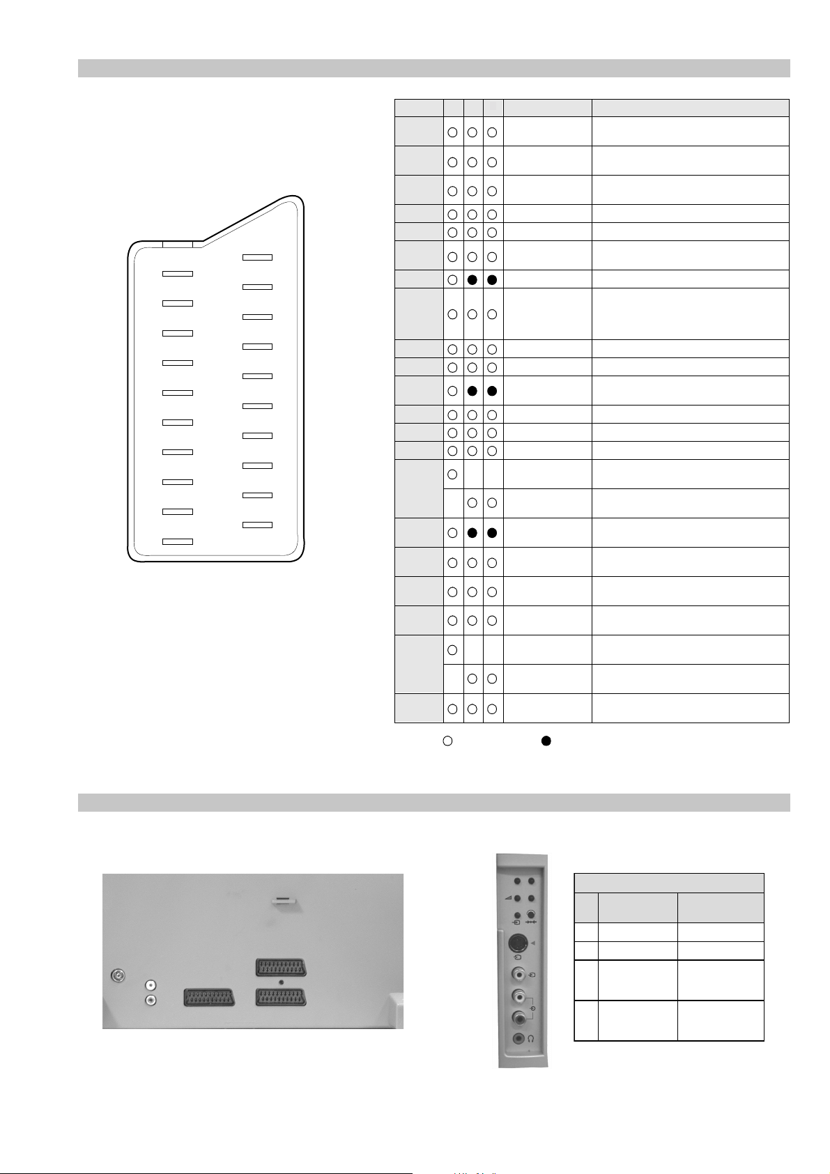
21 pin connector
21
19
17
15
13
11
9
7
5
3
1
20
18
16
14
12
10
8
6
4
2
Pin No 1 2 4 Signal Signal level
1 Audio output B
2
3
4 Ground (audio)
5 Ground (blue)
6 Audio input A
7 Blue input 0.7 +/- 3dB, 75 ohms positive
8 Function select
9 Ground (green)
10 Open
11 Green Green signal : 0.7 +/- 3dB, 75 ohms,
12 Open
13 Ground (red)
14 Ground (blanking)
15
16 Blanking input
17 Ground (video
18 Ground (video
19 Video output 1V +/- 3dB, 75ohms, positive sync 0.3V
20
21 Common ground
3
(right)
Audio output B
(right)
Audio output A
(left)
(left)
(AV control)
_ _ Red input 0.7 +/- 3dB, 75 ohms, positive
_ (S signal Chroma
input)
(Ys signal)
output)
input)
_ _ Video input 1V +/- 3dB, 75ohms, positive sync 0.3V
_ Video input
Y (S signal)
(plug, shield)
Standard level : 0.5V rms
Output impedence : Less than 1kohm*
Standard level : 0.5V rms
Output impedence : More than 10kohm*
Standard level : 0.5V rms
Output impedence : Less than 1kohm*
Standard level : 0.5V rms
Output impedence : More than 10kohm*
High state (9.5-12V) : Part mode
Low state (0-2V) : TV mode
Input impedence : More than 10K ohms
Input capacitance : Less than 2nF
positive
0.3 +/- 3dB, 75 ohms, positive
High state (1-3V) Low state (0-0.4V)
Input impedence : 75 ohms
(-3+10dB)
(-3+10dB)
1V +/- 3dB, 75ohms, positive sync 0.3V
(-3+10dB)
Connected Not Connected (open) * at 20Hz - 20kHz
Rear Connection Panel Front Connection Panel
p
- +
niP
oN
S-Video
socket
s
4
4
MONO
L/G/S/I
4
R/D/D/D
1dnuorG2dnuorG3tupni)langisS(Y,mho57Bd3-/+V1
4tupni)langisS(CBd3-/+V3.0
langiS leveLlangiS
noitarugifnocniptekcosoediVS
V3.0.cnySevitisop
Bd01+3-
evitisop,mho57
.cnyS
- 4 -
Page 5
AE-6B SELF DIAGNOSTIC SOFTWARE
The identification of errors within the AE-6B chassis is triggered in one of two ways :- 1: Busy or 2: De vice failure to respond to IIC. In the
event of one of these situations arising the software will first try to release the bus if busy (Failure to do so will report with a continuous
flashing LED) and then communicate with each device in turn to establish if a device is f aulty . If a device is found to be faulty the rele v ant
device number will be displayed through the LED (Series of flashes which must be counted) See table 1., non fatal errors are reported using this
method.
Each time the software detects an error it is stored within the NVM. See T able 2.
Table 1
egasseMrorrE
rorreoN00
devreseR10
)noitcetorPtnerruCrevO(PCO20
noitcetorPegatloVrevO30
cnySlacitreVoN40
norewoptarorrERKI50
norewoptaegdelwonkcasubCIIonMVN70
noitcetorPlatnoziroH80
norewoptaegdelwonkcaonrenuT90
rorrErossecorPdnuoS01
devreseR11
rorrEetarnacS21
rorrECAD31
rorrEdnekcaB41
rorrEecnegrevnoCcimanyD51
rorrEPIP61
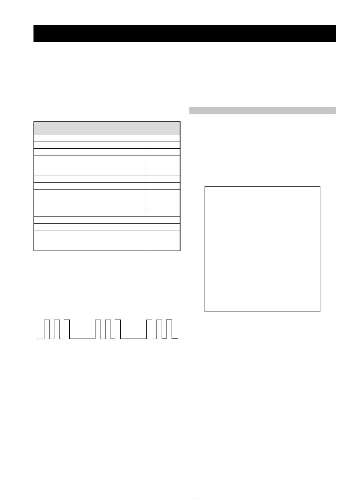
Flash Timing Example : e.g. error number 3
StBy LED
ON
ON ON
norewoptawolsenilatadro/dnakcolcsubCII60
How to enter into T able 2
DEL
edoC
1. T urn on the main po wer switch of the TV set.
2. Program Remote Commander for Operation in Service
Mode. [See Page 20].
2. Press ‘VIDEO’ ‘VIDEO’ > ‘MENU’ > ERROR MENU
on the Remote Commander.
3. The following table will be displayed indicating the error
count.
Table 2
UNEMRORRE
20E
30E
40E
50E
60E
70E
80E
90E
01E
11E
21E
31E
41E
51E
61E
SRUOH
SETUNIM
PCO
PVO
CNYSV
RKI
CII
MVN
TORPH
RENUT
PDNUOS
ETARNACS
CAD
DNEKCAB
NOCNYD
PIP
EMITGNIKROW
)552,0(
0
)552,0(
0
)552,0(
0
)552,0(
0
)552,0(
0
)552,0(
0
)552,0(
0
)552,0(
0
)552,0(
0
)552,0(
0
)552,0(
0
)552,0(
0
)552,0(
0
)552,0(
0
)552,0(
0
41
7
OFF
OFF
Note: T o clear the error count data press ‘80’ on the Remote
commander.
- 5 -
Page 6
4-1. Electrical Adjustments
SECTION 4 CIRCUIT ADJUSTMENTS
Service adjustments to this model can be performed using the
supplied remote Commander RM-934.
Programming the Remote Commander for
Operation in Service Mode
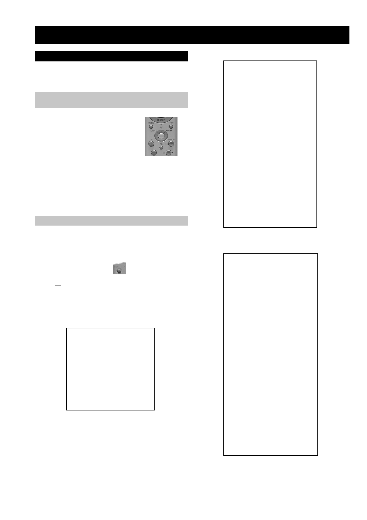
1. Press the VCR/TV/DVD button until the
TV LED lights.
2. Press and hold the yellow button for
approx. 5 seconds until the TV LED
flashes quickly .
3. Press 99999. All three LED’s should light.
The remote commander is now set to Service Mode.
4. T o return the remote commander to normal operation mode
repeat steps 1. and 2. then press 00000. All three LED’s
should light.
The remote commander is now set to normal mode.
Setting the TV into Service Mode
1. Program the remote commander for operation in Service
Mode as described above.
YRTEMOEG
HTLBA
EDOMLBA
LBAP
EZISV
NOITISOPV
PMOCV
NILV
NOITCERROCS
EZISH
PMANIP
NIPRENROCPU
NIPM
NIPRENROCOL
MUIZEPART
NOITISOPH
WOBCFA
ELGNACFA
KLBTFEL
KLBTHGIR
TCEPSAV
1MITBKA
2MITBKA
RKI
GNH
GNV
)3,0(
)3,0(
)3,0(
)3,0(
)3,0(
)1,0(
0
0
)51,0(
)36,0(
)36,0(
)51,0(
)51,0(
)36,0(
)36,0(
)36,0(
)36,0(
)51,0(
)36,0(
)51,0(
)51,0(
)36,0(
)36,0(
)36,0(
51
53
33
1
7
7
44
23
92
2
92
2
04
8
9
43
71
74
2
0
1
0
0
2. T urn on the TV main po wer switch.
3. Press the video standby button on the remote
commander twice.
‘TT ’ will appear in the upper right corner of the screen.
Other status information will also be displayed.
4. Press ‘MENU’ on the remote commander to obtain the
following menu on the screen.
yrtemoeG
ecivreS
etarnacS
CAD
.vnoC.nyD
PiP
dnuoS
tsujdaFI
uneMrorrE
)1002nuJ(41.0vB6EA
hFFhFFatadyrotcaF
G1143PSM:eciveDPSM
5. Move to the corresponding adjustment item using the
up or down arrow b uttons on the Remote Commander.
6. Press the right arrow button to enter into the required menu item.
7. Press the ‘Menu’ button on the Remote Commander to quit the
Service Mode when all adjustments have been completed.
.VNOC.NYD
EGNAR
LpuY
LAV
LwolY
LAV
LpuWOBM
LAV
LwolWOBM
LAV
LPMAH
LAV
RpuY
LAV
RwolY
LAV
RpuWOBM
LAV
RwolWOBM
LAV
RPMAH
LAV
YPU
LAV
YWOL
LAV
TATSH
LAV
RROCPU
LAV
RROCWOL
LAV
)36,0(
)1,0(
)36,0(
)1,0(
)36,0(
)1,0(
)36,0(
)1,0(
)36,0(
)1,0(
)36,0(
)1,0(
)36,0(
)1,0(
)36,0(
)1,0(
)36,0(
)1,0(
)36,0(
)1,0(
)36,0(
)1,0(
)36,0(
)1,0(
)36,0(
)1,0(
)36,0(
)1,0(
)36,0(
)1,0(
)36,0(
36
0
03
0
13
0
13
0
23
0
73
0
03
0
03
0
23
0
23
0
63
0
13
0
33
0
33
0
43
0
91
·
Note :
· After carrying out the service adjustments, to prevent the
customer accessing the ‘Service Menu’ switch the TV set
OFF and then ON.
- 20 -
Page 7
TSUJDAFI
UNEMRORRE
etumotuA
niaGoiduA
gnitaGL
ECIVRES
LOCBUS
EUHBUS
PRAHSBUS
THGIRBBUS
TNOCBUS
EVIRD-R
EVIRD-G
EVIRD-B
FFOTUCR
FFOTUCG
FFOTUCB
TXTrB
DSOrB
)36,0(
)36,0(
)36,0(
)36,0(
)51,0(
)36,0(
)36,0(
)36,0(
)36,0(
)36,0(
)36,0(
)51,0(
)51,0(
1
0
0
jdA
13
03
31
21
05
jdA
jdA
82
42
64
7
01
20E
30E
40E
50E
60E
70E
80E
90E
01E
11E
21E
31E
41E
51E
61E
EMITGNIKROW
SRUOH
SETUNIM
PCO
PVO
CNYSV
RKI
CII
MVN
TORPH
RENUT
PDNUOS
ETARNACS
CAD
DNEKCAB
NOCNYD
PIP
)552,0(
0
)552,0(
0
)552,0(
0
)552,0(
0
)552,0(
0
)552,0(
0
)552,0(
0
)552,0(
0
)552,0(
0
)552,0(
0
)552,0(
0
)552,0(
0
)552,0(
0
)552,0(
0
)552,0(
0
41
7
Sub Brightness Adjustment
1. Input a Monoscope pattern.
2. Program the Remote Commander for operation in Service Mode.
CAD
[ See Page 20 ].
3. Press ‘VIDEO’ ‘VIDEO’ 13 on the Remote Commander.
GIFNOC
TNOCNIPM
NILH
PARTH
LIOC.TOR
HPSUCOHP
)552,0(
)552,0(
)552,0(
)552,0(
)552,0(
00000000
69
38
721
031
09
4. Adjust the ‘Sub-Brightness’ data so that there is barely a
difference between the 0 IRE and 10 IRE signal levels.
Sub Contrast Adjustment
1. Input a video signal that contains a small 100% white area on a
black background.
2. Connect an digital voltmeter to Pin 10 of J7378 [C Board].
3. Program the Remote Commander for operation in Service Mode.
DNUOS
N-M
D-M
S-M
M-S
M-D
M-N
EBB
1B
2B
3B
4B
5B
LWS
FWS
DACMACIN
rorrEMACIN
oeretS
)115,0(
)1-,821-(
)721+,0+(
)721+,0+(
)1-,821-(
)3201,0(
)86+,0+(
)69+,69-(
)69+,69-(
)69+,69-(
)69+,69-(
)69+,69-(
)0+,821-(
)04+,5+(
)7402,0(
)721+,821-(
002
02-
02+
01+
01-
694
82+
0+
0+
0+
0+
0+
0+
03+
10001
0
0+
[ See Page 20 ].
4. Adjust the Sub-Contrast [ Using ‘VIDEO’ ‘VIDEO’ ‘11’ ] to
obtain a voltage of 105 +/- 5V .
Sub Colour Adjustment
1. Recei ve a PAL colour bar signal.
2. Connect an oscilloscope to Pin 6 of CN7001 [A Board].
3. Program the Remote Commander for operation in Service Mode.
[ See Page 20 ].
4. Adjust the ‘Sub Colour’ [ Using ‘VIDEO’ ‘VIDEO’ ‘12’ ] so
that the Cyan, Magenta and Blue colour bars are of equal levels
as indicated below .
Same Level
sutatS0110000000
B-Out Wav eform
- 21 -
Page 8
Deflection System Adjustment
72
RKEDAnoitanitseD
82
RKEDAnoitanitseD
13
elbasiD/elbanEffotuhSotuA
63
tsetNO/FFO)MV(noitaludoMyticoleV
14
MVNesilaitini-eR
34
dnuosAlauDtceleS
44
dnuosBlauDtceleS
54
dnuosonoMtceleS
64
dnuosoeretStceleS
84
nigrivnonsaMVNteS
94
nigrivsaMVNteS
35
elbasiD/elbanEnoitaludomrevOMF
55
)SPLA/YNOS(noitcelesrenuT
95
stracS2roPIP+stracS3ledoMtceleS
86
)melborpN(erusaemretnuoc62XelbasiD/elbanE
37
)47.6/5.6(metsys2K/DnotiewZelbanE
47
)47.5/5.6(metsys3K/DnotiewZelbanE
87
thgirllufecnalaB
97
tfelllufecnalaB
78
tsetsyeklacoL
99
unememiTgnikroWdnarorrEyalpsiD
00
ffoedom'TT'
10
mumixamerutciP
20
muminimerutciP
30
%53otemuloVenohpdaeh/rekaepsteS
40
%05otemuloVenohpdaeh/rekaepsteS
50
%56otemuloVenohpdaeh/rekaepsteS
60
%08otemuloVenohpdaeh/rekaepsteS
70
edomgniegA
80
noitidnoCgnippihS
11
tnemtsujdaerutcipbuS
21
tnemtsujdaruolocbuS
31
tnemtsujdassenthgirBbuS
41
tnemtsujdanoitisoPHtxeT
51
tseTlioCnoitatoR
61
%05levelerutciP
91
elbasiD/elbanEedoMyrotcaF
12
RKEDAnoitanitseD
22
LBnoitanitseD
32
RKEDAnoitanitseD
42
UnoitanitseD
52
RKEDAnoitanitseD
62
LBnoitanitseD
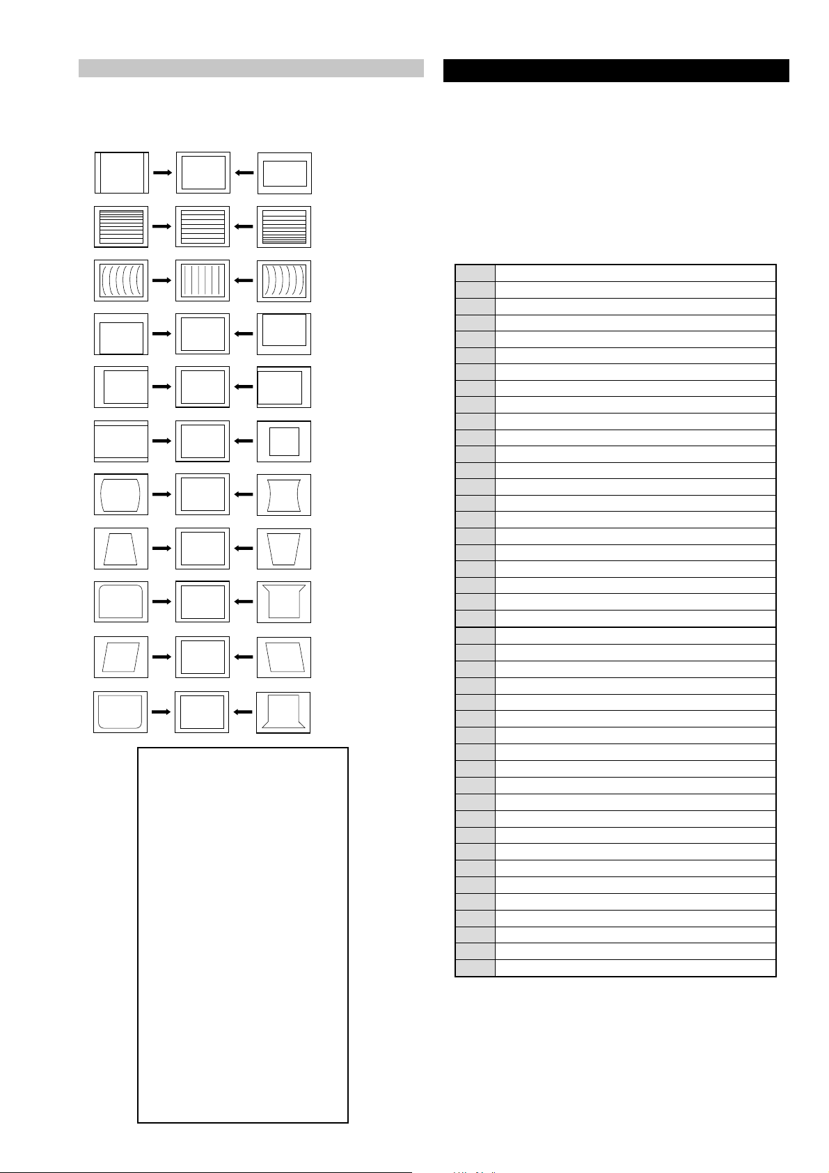
4-3. TEST MODE 2:
1. Program the Remote Commander for operation in Service Mode.
[ See Page 20 ] and enter into the ‘Geometry’ service menu.
2. Select and adjust each item in order to obtain the optimum image.
V SIZE
V LIN
AFC BOW
V POSITION
H POSITION
H SIZE
PIN AMP
T est Mode 2 is available by rogramming the Remote Commander for
operation in Service Mode [ As sho wn on P age 20 ] then pressing the
‘VIDEO’ button twice, OSD ‘TT’ appears. The functions described
below are available by selecting the two numbers. T o release the ‘T est
mode 2’, press 00, 10, 20 ... twice or switch the TV set into Stand-by
mode. In ‘TT Menu’ mode, it is possible to remove the Menu from
the screen by pressing the Speaker Off button once. Pressing the
Speaker OFF button a second time will cause the Menu to reappear .
The function is kept even when the menu is not displayed on
screen !!.
TRAPEZIUM
UP CORNER PIN
AFC ANGLE
LO CORNER PIN
YRTEMOEG
HTLBA
EDOMLBA
LBAP
EZISV
RKI
NOITISOPV
PMOCV
NILV
EZISH
PMANIP
NIPM
WOBCFA
KLBTFEL
1MITBKA
2MITBKA
GNH
GNV
NOITCERROCS
NIPRENROCPU
NIPRENROCOL
MUIZEPART
NOITISOPH
ELGNACFA
KLBTHGIR
TCEPSAV
)3,0(
)3,0(
)3,0(
)3,0(
)3,0(
)1,0(
0
0
)51,0(
)36,0(
)36,0(
)51,0(
)51,0(
)36,0(
)36,0(
)36,0(
)36,0(
)51,0(
)36,0(
)51,0(
)51,0(
)36,0(
)36,0(
)36,0(
51
53
33
1
7
7
44
23
92
2
92
2
04
8
9
43
71
74
2
0
1
0
0
- 22 -
Page 9

5-1. BLOCK DIA GRAMS (1)
RIGHT OUT
CN2501
AUDIO PROCESSOR
IC2000
A 1/2 ( )
VIDEO AND AUDIO PROCESSORS,
AUDIO OUTPUT, VERTICAL DEFLECTION
60
MONO IN (AM)
67
IF INI
SCL
3
SDA
37
56
SC1 OUT L
SC1 IN L
2
SC1 OUT R
57 SC1 IN R
36
27
28
30
TO
SPEAKERS
SPEAKER OUT R
SPEAKER OUT L
SUBWOOFER OUT
HEADPHONE
AMPLIFIER
IC2001
5
3
1
7
R
1
4
CN1000
TO A BOARD
SHEET 2
71
72
RIGHT IN
LEFT OUT
LEFT IN
BLUE IN 1
GREEN IN 1
RED IN 1
VIDEO OUT 1
VIDEO IN 1
RIGHT OUT
34
53
SC2 OUT L
SC2 IN L
SC2 OUT R
54
SC2 IN R
33
1
3
2
6
11
7
15
20
19
RIGHT IN
LEFT OUT
LEFT IN
BLUE IN 2
GREEN IN 2
RED IN 2
VIDEO OUT 2
VIDEO IN 2
CN1001 (1/2)
XTAL IN
XTAL OUT
TU100
SCL
SDA
FM/AM
QSS
VIDEO
SCL
SDA
RIGHT OUT
50
SC3 IN L
51
SC3 IN R
1
3
2
6
19
20
RIGHT IN
LEFT OUT
LEFT IN
VIDEO OUT 2
V/Y IN 3
CN1001 (2/2)
KEY
47
48
1
6
4
9
LEFT
Y/CVBS FRONT
RIGHT
CN2000
FR IN L
FR IN R
LED
2
1
SIRCS
CN0103
BACKEND: DEFLECTION -
RGB PROCESSOR
IC7002
33
YSYM 2
34
B2 IN
G2 IN
36
R2 IN
35
30
26
R OUT
B OUT
FS 100
B TXT
G TXT
R TXT
52
Y1 IN
U IN 100
28
G OUT
53
CB1 IN
54
CR1 IN
HS IN
60
VS IN
59
V IN 100
H SYNC
V SYNC
PIP Y
56
Y2 IN
PIP CB
57
CB2 IN
PIP CR
58
CR2 IN
63
EXTRA PARA
64
DF PARA
1
EW OUT
17
HD OUT
18
HP IN
20
X RAY IN
5
VDP OUT
6
VDN OUT
16
VPROT
45VM OUT
AUDIO AMPLIFIER
IC2500
5IN R
1
IN L
IN W
9
MUTE W
6
12
3
OUT R
OUT W
RIGHT
LEFT
WOOFER
10
MUTE
14
OUT L
MP PARA
DF PARA
E/W
H DRIVE
AFC PULSE
X RAY
PART OF
V PROT
Q5400
Q5401
V OUT IC5400
1
7
DAC IC5103
3
7
DF PHOCUS PHASE
M PIN CONT
OP. AMP
IC5104
1
4
ROT -
ROT+
5
36
OP. AMP IC5301
7
6
COMPARATOR IC5302
5
62
DYNAMIC
CONVERGENCE
IC5200
6
3
OP. AMP
IC5201
3
2
1
3
1
CY+
CY-
VM
2
8
AFC PULSE
X RAY
6
5
3
1
H DRIVE
E/W
DF PARA
MP PARA
1
6
B-
B+
5
4
3
2
G+
G-
R+
R-
3
H CENTRE
4
2
M PIN CONT
DF DRIVE
1
3
ROT-
ROT+
1
WOOFER
2
6
R OUT
L OUT
5
L IN
3
R IN
CN2502
TO
SUBWOOFER
TO H2 BOARD
CN2908
CN2500
CN5100
TO
ROTATION
COIL
CN5002
TO D BOARD
CN8810
CN7001
TO C BOARD
CN7301
TO D BOARD
CN8620
CN5200
TO VM BOARD
CN7442
R OUT
L OUT
J2000
L
CN7000
CN5801
TO F2 BOARD
CN0981
TO H2 BOARD
CN2906
Y IN 100
VM
5
4
1
CN7442
QP (+)
QP (-)
VM AMPLIFIER
BUFFER Q7401
VM AMPLIFIER
BUFFER Q7400
VM AMPLIFIER
BUFFER Q7405
VM AMPLIFIER
BUFFER Q7403
VM AMP
OUTPUT Q7407
VM AMP
OUTPUT Q7406
4
7
8
2
3
VM
VM
1
QP (+)
QP (+)
QP (-)
QP (-)
VM ( )
VELOCITY
MODULATION
+9V
CN7444
QP-
QP+
VM
NECK ASSY
TO A BOARD
CN7000
- 23 -
Page 10

5-1. BLOCK DIA GRAMS (2)
Y IN 100
BLK 100
H SYNC
V SYNC
RED IN 1
GREEN IN 1
BLUE IN 1
RED IN 2
VIDEO RF
V IN 1
BLK 1
BLK 2
GREEN IN 2
BLUE IN 2
100Hz BUFFER
Y SCAN RATE
BACKEND
Q3300
CN0101
SCAN RATE CONVERTER,
COLOUR DECODER AND I/O
VIDEO SWTICH
IC3200
A 2/2 ( )
VIDEO AND AUDIO PROCESSORS, AUDIO
OUTPUT, VERTICAL D EFLECTION
2 AY OUT 100
8
NC
H OUT 100
23
V OUT 100
39
40
41
R IN 1
46
G IN 1
47
B IN 1
48
R IN 2
52
CVBS 1
CVBS 2
5
AGC
17
FBL 1
38
FBL 2
37
G IN 2
B IN 2
79
76
74
70
69
63
62
61
58
57
56
55
54
TO G BOARD
CN6008
AU OUT 100
AY OUT 100
RESERVED XCLK OUT
X IN
CVBS OUT 2
CVBS OUT 3
CVBS 7
CVBS 6
CVBS 3
X OUT
CVBS OUT 1
CVBS 5
CVBS 4
53
PICTURE IN PICTURE
IC3100
1
X IN
2
XQ
HSP
4 VSP
3
28
18
17
16
15
CVBS 1
OUT 1
OUT 2
OUT 3
SEL
CVBS PIP
PIP CR
PIP Y
PIP CB
PIP BLK
CVBS PIP
C FRONT
Y/CVBS FRONT
V IN 2
C IN 3
V/Y IN 3
100Hz BUFFER
U SCAN RATE
BACKEND
Q3302
4
CS
3
SDA
2
SCL
B20
12C DISABLE
A20
KEY
A19
TXT VIDEO
B17
V SYNC
A17
H SYNC
B16
LINE MUTE
B15
MODE 2
A15
AV LINK
A14
MODE 1
B13
FS 100
A13
AUDIO MUTE
B12
R TEXT
A12
RESET AUDIO
B11
G TEXT
B10
B TEXT
A9
DGC RY
B8
MAIN RY
A8
COINCIDENCE
B7
OCP
A7
GROUP DELAY
B6
OVP
B5
MODE 3
A5
AGC
B4
SIRCS
A4
LED
B3
SDA
A3
SCL
PART OF
OVERVOLTAGE
PROTECTION
Q5816
COINCIDENCE
DETECTOR
Q1005
VIDEO RF
CVBS TXT
V SYNC
H SYNC
12 C ADAPTOR
5V - 3.3V
Q3500
12 C ADAPTOR
5V - 3.3V
Q3501
OVP
+3.3V
2
1
CN6200
TO M BOARD
CN0001
CN0102
SERVICE CONNECTOR
TO A BOARD
SHEET1
6dB AMPLIFIER
FOR THE
SELECTABLE
OUTPUT CVBS
(3RD SCART)
Q3200
6dB AMPLIFIER
FOR THE
SELECTABLE
OUTPUT CVBS
(3RD SCART)
Q3202
100Hz BUFFER
U SCAN RATE
BACKEND
Q3301
6dB AMPLIFIER
FOR THE
MONITOR
OUTPUT CVBS
(2ND SCART)
Q3204
V OUT 3
6dB AMPLIFIER
FOR THE
MONITOR
OUTPUT CVBS
(2ND SCART)
Q3201
V OUT 2
V IN 100
U IN 100
PICTURE TUBE
CN7301
+12V
R-
TO D BOARD
HV (T8800)
R
G
B
HV
VOLTAGE DET
Q7354, 7350
8
VO
IC7350
VIDEO OUT (BLUE)
8
VO
IC7325
VIDEO OUT (GREEN)
1
VB
8
VO
IC7300
VIDEO OUT (RED)
8
9
10
TO D BOARD
FV (T6804)
G4
G2
13
H1
3
H1
5
G2
RV7375
CN7300
TO D BOARD
CN6500
FV
J7375
C (
)
CRT DRIVE
3
VI
5
IK
1
VB
3
VI
5
IK
1
VB
3
VI
5
IK
STANBY SW
Q7353
1
2
3
4
5
6
9
STANBY SW
Q7352
STANBY SW
Q7355
R+
G-
G+
B-
B+
IK
TO A BOARD
CN7001
TO A BOARD
CN2000
TO A BOARD
CN2502
VIDEO
HEADPHONES
R
L
WOOFER MUTE
CN2908
R OUT
R IN
L IN
CN2906
AUDIO L
AUDIO R
Y/CVBS
C
1
2
3
5
6
9
4
2
J2900
1
2
4
3
Y/C
CN2900
H2( )
AUDIO IN, Y/C IN,
HEADPHONE IN
J2900
6L OUT
AC
IN
CN6991
1
2
F4 ( )
POWER
POWER SWITCH
CN6992
1
5
TO G BOARD
CN6001
IC0991
OUT
H1 ( )
STBY+5V
LED AND
IR RECEIVER
D0993
LED
SIRCS
CN0991
2
1
TO A BOARD
CN003
- 24 -
Page 11

CN8611
6
4
5
3
2
1
V -
CN8614
TO A BOARD
CN8001
V DY
V- DY+
DY ASSY
V- DY-
H DY
H- DY+
H- DY-
6
5
11
1
2
4
7
9
8
HV
12
+200V
T8800
F
SC
13
V +
H -
H +
H +
H -
1
3
5
TO C BOARD
CN7300
CN8612
V +
V -
13
24
T8852
CN8810
Q8100,8102
TO A BOARD
CN5801
V STAT
+
-
2
3
COMPARATOR IC8100
1
4
+
-
7
6
8
5
1
2
3
4
DF DRIVE
H CENTRE
M PIN CONT
1
2
3
4
5
6
7
8
CN8620
DF PARA
MP PARA
E/W
H LIN
H DRIVE
AFC PULSE
ABL
X RAY PROTECT
+
-
2
3
COMPARATOR IC8101
1
4
+
-
7
6
8
5
Q8136,8137
+
-
2
3
COMPARATOR IC8103
1
4
+
-
7
6
8
5
Q8201,
8202,8118
31
42
T8802
+
-
2
3
OP. AMP IC8102
1
4
+
-
7
6
8
5
31
42
T8801
Q8122
H OUT Q8804
PIN OUT Q8803
Q8112
Q8807
Q8123
Q8120
M PIN
CONTROL
Q8805
H LIN
Q8806
DF DRIVE
Q8851
Q8203
+8
+8
HD1
TO A BOARD
CN5002
D ( )
DEFLECTION
D8819
D8808
+15V
D8807
-15V
D8805
5-1. BLOCK DIA GRAMS (3)
DGC
10
+6V
AU (+)
CN6001
RECT
D6102
AC IN
AC IN
TO F4 BOARD
CN6992
G ( )
POWER
SUPPLY
1
5
CN6002
CHECK
CHECK
1
2
1
2
3
CN6003
CN6004
PFC
PFC
1
3
CN6008
MAIN RY
DGC RY
TO A BOARD
CN6200
1
2
DGC
DGC
3
1
T6003
4
2
3
1
T6101
4
2
9
7
8
RELAY
SWITCH
Q6103
11
12
13
14
15
16
17
18
1
2
3
7
9
6
8
IC6001
MAIN BRIDGE
RECTIFIER
1
V SENSE
2
F/B
CT
4RT
8
9
VC 1
OCP
3
TIMER
7
SS
6
18
16
15
14
12
10
VD
VG
VG (L)
VC 2
VS
VB
RELAY
SWITCH
Q6101
RELAY
RY6001
RELAY
RY6002
MAIN RECT
D6001
MOSFET
TRANSISTOR
USED BY
SWITCHING
CIRCUIT Q6006
MOSFET
TRANSISTOR
USED BY
SWITCHING
CIRCUIT Q6007
1
2
4
3
PH6001
T6002
RECT
D6010
RECT
D6016
1
2
IC6003
TO A BOARD
CN6202
6
5
CN6006
AU (+)
+135V
+200V
D6004
Q6104
Q6105
FOR CHECK
+11V
- 25 -
Page 12

5-2. CIRCUIT BOARD LOCATION
5-3. SCHEMATIC DIAGRAMS AND
PRINTED WIRING BOARDS
Note :
• All capacitors are in µF unless otherwise noted.
• pF : µµF 50WV or less are not indicated except for
electrolytic types.
• Indication of resistance, which does not have one for
rating electrical power, is as follows.
Pitch : 5mm
Electrical power rating : 1/4W
• Chip resistors are 1/10W
• All resistors are in ohms.
k = 1000 ohms, M = 1000,000 ohms
• : nonflammable resistor.
• : fusible resistor.
• : internal component.
• : panel designation or adjustment for repair.
• All variable and adjustable resistors have
characteristic curve B, unless otherwise noted.
• All voltages are in Volts.
• Readings are taken with a 10Mohm digital mutimeter.
• Readings are tak en with a color bar input signal.
• Voltage variations may be noted due to normal production
tolerences.
•: B + bus.
• : B - bus.
• : RF signal path.
• : earth - ground.
• : earth - chassis.
Reference Information
RESISTOR RN
: METAL FILM
RC
: SOLID
FPRD
: NON FLAMMABLE CARBON
FUSE
: NON FLAMMABLE FUSIBLE
RS
: NON FLAMMABLE METAL OXIDE
RB
: NON FLAMMABLE CEMENT
RW
: NON FLAMMABLE WIREWOUND
: ADJUSTMENT RESISTOR
COIL LF-8L
: MICRO INDUCTO R
CAPACITOR TA
: TANTALUM
PS
: STYROL
PP
: POLYPROPYLENE
PT
: MYLAR
MPS
: METALIZED POLYESTER
MPP
: METALIZED POLYPROPYLENE
ALB
: BIPOLAR
ALT
: HIGH TEMPERATURE
ALR
: HIGH RIPPLE
Les composants identifiés par une trame et
par une marque sont d'une importance
critique pour la sécurité. Ne les remplacer
que par des pièces de numéro spécifié.
specified.
Note :
The components identified by shading
and marked are critical for safety.
Replace only with the part numbers
specified in the parts list.
Note :
CVM Board
A Board
S1 Board
VM
C
H
D1
A
J
A2
N
D
A1
D2
C
A
5-1. BLOCK DIA GRAMS (4)
VM Board
C Board
A Board
H2 Board
M Board
G Board
D Board
H1 Board
F4 Board
NVM
MEMORY
IC0001
CN001
A3 SCL
B3 SDA
A4 LED
B4 SIRCS
A5
B6 OVP
TO A BOARD
CN0101
A7 GROUP DE LAY
B7 OCP
A8 COINCIDENCE
B8 MAIN RY
A9 DGC RY
B10 B TEXT
B11 G TEXT
A12 RESET AUDIO
B12 R TEXT
A13
B13 FS 100
A14 MODE 1
A15 AV LINK
B15
B16 LINE MUTE
A17 H SYNC
B17 V SYNC
A19 TXT VIDEO
B19
A20 KEY
B20 12C DISABLE
5
7
6
AGC
MODE 3
AUDIO MUTE
MODE 2
RESET 100
MAIN RELAY DRIVE R Q0002
DEGAUSING COIL RELAY
DRIVER Q0003
12C DISABLE
DRIVER (CS)
Q0011
12C SWITCH
(CONNECT
12C BUS 0
AND BUS 1
TOGETHER)
Q0007,
0008
12C SWITCH
(CONNECT
12C BUS 0
AND BUS 1
TOGETHER)
Q0009,
0010
SWITCH
NVM WC* CONTROL
DURING RESET Q0013
MICRO CONTROLLER
IC0002
28
LED
76
SIRCS
6
AGC
22
AGC
93
MODE 3 (1)
94B5MODE 3 (2)
OVP/OCP
29
GROUP DELAY
80
24
OCP FLAG
59
COINDIDENCE
17
MAIN RY
16
DGC RY
46
B TEXT
47
G TEXT
25
RESET AUDIO
48
R TEXT
13
AUDIO MUTE
43
COR*
52
VDS
4
MODE 1
2
MODE 2
18
MUTE LINE
53
H SYNC
55
V SYNC
32
TXT VIDEO
96
RESET 100
5
AV LINK OUT
KEY
12C DISABLE
SDA 0
SCL 0
SCL 1
SDA 1
AV LINK IN
97
82
81
83
84
71
70
69
A(0)
49
A(1)
40
A(2)
39
A(3)
38
A(4)
27
A(5)
26
A(6)
23
A(7)
15
A(8)
67
A(9)
66
A(10)
65
A(11)
64
A(12)
37
A(13)
36
A(14)
8
A(15)
33
A(16)
51
A(17)
50
9
RD*
10
WR*
D(0)
85
D(1)
86
D(2)
87
D(3)
88
D(4)
89
D(5)
90
D(6)
91
D(7)
92
98
NVM WL*
73
RESET
78
79
COMPARATOR
(AV-LINK CIRCUIT)
IC0004
1
2
+
-
3
4
CIRCUIT
3
RESET
IC0003
8
7
6
+
5
A(0)
A(1)
A(2)
A(3)
A(4)
A(5)
A(6)
A(7)
A(8)
A(9)
A(10)
A(11)
A(12)
A(13)
A(14)
A(15)
A(16)
A(17)
D(0)
D(1)
D(2)
D(3)
D(4)
D(5)
D(6)
D(7)
M ( )
SRAM (TELETEXT
PAGES STORAGE)
IC0005
20
19
18
17
16
15
14
13
3
2
31
1
12
4
11
7
10
9
32
5
21
22
23
25
26
27
28
29
MICRO PROCESSOR
- 26 -
Page 13

- 27 -
~ A Sc hematic [ Video & Audio Pr ocessors, A udio Output,
Vertical Deflection] page 1/2~
Page 14

- 28 -
~ A Sc hematic [ Video & Audio Pr ocessors, A udio Output,
Vertical Deflection] page 2/2~
Page 15

ABCDE F
G
HIJKLMN
1
2
3
~ H1 Board Schematic Diagram ~
~ H2 Board Schematic Diagram ~
~ F4 Board Schematic Diagram ~
4
5
10
6
7
8
9
11
~ VM Board Schematic Diagram ~
- 33 -
Page 16

~ G Schematic [ P o wer Supply ] ~
- 35 -
Page 17

ABCDE F
1
2
3
4
G
HIJKLMN
5
6
7
8
9
10
11
~ C Board Schematic [ R-G-B Out ] ~
- 38 -
Page 18

~ D Schematic [ Deflection ] ~
- 36 -
Page 19

- 40 -
~ M Schematic [ Micro Processor ] ~
Page 20

5-4. SEMICONDUCTORS
1
16
17
32
1
14 15
28
CXAB070AP
MCZ3001D
18
1
CXA1875AM-T4
16 9
1
( TOP VIEW )
LM318P
PST573IMT
LM358N
LM393DT
10
LM393N
M24C16-MN6T(A)
7
6
8
5
9
2
3
1
LM78L05ACZ
8
4
SAA5665HL/M1D/0358
IN
OUT
GND
25
123
+
100
1
26 50
1
Vcc
Out
3
2
Gnd
76
75
51
CXA2100AQ-TL
51
52
64
1
(TOP VIEW)
K6T2008V2A-YF70T00
MSP3411G-QA-B10
33
32
20
19
9
10
18
26
68
1
( TOP VIEW )
61
60
52
44
433527
SBX3081-51(30)
SDA9488X-B23GEG
NJM3404AD-W
UPC4558G2
85
1
4
( TOP VIEW )
LA6500-FA
PQ30RV11
1 : V IN
2 : V OUT
3 : GND
4 : ON/OFF CONTROL
STV9379
1
2
3
4
1
7
- 41 -
Page 21

TCET1103G
115
1
2
3
TDA6111Q/N4
DTA144EK
DTC144TKA-T146
2SA1162-G
C
E
B
DTA144ESA
2SA933AS-QT
2SC2785-HFE
SE135N-LF4
2
1
2SA1837(LBS2S0N)
3
1V
OUT
2 COLLECTOR
3 GND
SENSE
19
TDA7497
VPS9402-A32GEG
1
6180
60
C
E
L7809CV/LSY
STP5NB40FP
STP5NB40(030Y)
2SC5698-CA
2S5696-SONY-CA
MSB709-RT1
MSD601-RST1
M1MA152WA-T1
UN2111
UN213
2SK2036(TE85L)
B
B
C
E
2SB734-34
2SC2688(5)-LK
20
21
(TOP VIEW)
BA12T
BAO33T
IRF614-005
IRF620
SPA07N60C2
2SA2005
2SC5511
B
E
C
41
40
RB705D
3
2
E
E
BAS216
1
2
3
1
B
C
- 42 -
Page 22

BAS316-115
MMDL914T1
UDZSTE-176.2B
ANODE
CATHODE
BYV98-200-RAS 15/12
CATHODE
ANODE
D1NL20U
EGP20G
EL1Z
GP08D
UF4005PKG23
FBIU4D7MA-B
RBV-406B
S1VB40
GS1B460/45
D2S4MTA1
ERA38-06
ERA85-009
HZS9.1NB2
MTZJ-13B
MTZJ-33B
MTZJ-3.6A
MTZJ-4.7C
CATHODE
ANODE
MTZJ-T-77-22
RD15ES-B2
RD39ES-B2
RD5.6ESB2
1SS119-25
1SS133T-77
TLHK5190
ANODE
CATHODE
CATHODE
ANODE
- 43 -
Page 23

5-5 IC BLOCK DIAGRAMS
A BOARD IC6202/IC6207/IC6205 BA033T/BA12T
1
REFERENCE
VOLTAGE
2
A BOARD IC1201 TDA7497
VOLUME
1
30K
VOLUME
5
30K
-
+
2
MUTE/STBY
PROTECTIONS
3
14
OP AMP
9
10
60K
12
OP AMP
G BOARD IC6001 MCZ3001D
Remote
1
Vsense
5
SS
DVLD
15v/8v
7
4 3 2
Osc
18
Internal
ref 5v
Centre
F/B
43
Latch
OFF
Sel=34v
Timer
8
Driver
Reg. 10v
TSD
Level
Shift
Control
Logic
OCP
6
14
16
15
10
12
11
9
- 44 -
Page 24

A BOARD IC2000 MSP3411G
65 68 13 45 7 6
25
23
28
31
30
34
33
37
36
SBUS Interface
DEMODULATOR
IDENT
DFP
A/D
A/D
SCART Switching Facilities
I2C Interface
D/A
D/A
D/A
D/A
D/A
D/A
56
57
59
60
47
48
50
51
G BOARD IC6003 SE135N-LF4
A BOARD IC5400 STV9379
2 6 3
1
7
-
POWER
AMPLIFIER
+
8 7 269
FLYBACK
GENERATOR
THERMAL
PROTECTION
A BOARD IC5301/IC5302 LM393TD
15 4 3
1
-
+
2
3
A BOARD IC5300 LM358N
1
2
++
--
3
5
4
7
-
+
6
5
8
7
6
5
4
- 45 -
 Loading...