

Sony CFSK-1066-S Service manual
CFS-K1066/K1066S
SERVICE MANUAL
Photo : CFS-K1066S
SPECIFICATIONS
Frequency range CFS-K1066
FM : 87.6 – 108MHz
AM : 530 – 1,710kHz
CFS-K1066S
FM : 87.6 – 108MHz
MW : 530 – 1,605kHz /SW1 : 2.3 – 7 MHz/
SW2 : 7 – 22MHz
IF FM : 10.7MHz/AM/MW/SW : 455kHz
Aerials FM/SW : Telescope/AM/MW : Built-in ferrite bar
Recording system 4-track, 2-channel stereo
Frequency response 100 – 10,000Hz
Speakers Woofer : 10cm (4 inches) dia., cone type/
Tweeter : 2cm (4/5 inches) dia.
Input Mixing microphone input jack (mini jack) (2),
sensitivity 3 mV. for low impedance microphone
Output Headphones jack (stereo minijack),
for 16 – 68 ohms impedance headphones
E Model
Model Name Using Similar Machanism NEW
T ape Transport Mechanism T ype MF-K1066
Maximum Power output
2.3W+2.3W
Battery life FM Recording : Sony R20P : Approx. 16 hours/
Sony LR20 alkaline : Approx. 36 hours
Playback : Sony R20P : Approx. 8 hours/Sony
LR20 alkaline : Approx. 21 hours
Power requirements CFS-K1066 : 220V AC 60Hz
CFS-K1066S : 110 – 120V/220 – 240V AC
selectable, 50/60Hz
Power consumption AC 14 W
Dimensions Approx. 579 x 206 x 197 mm (w/h/d)
(22 7/8 x 8 1/8 x 7 7/8 inches) incl. projecting and
controls, not incl. handle
Mass Approx. 4.6 kg (10 lb 2 oz) incl. batteries
Supplied Accessories
AC power cord (1),
Microphone (1)
MICROFILM
Design and specifications are subject to change without notice.
RADIO CASSETTE-CORDER
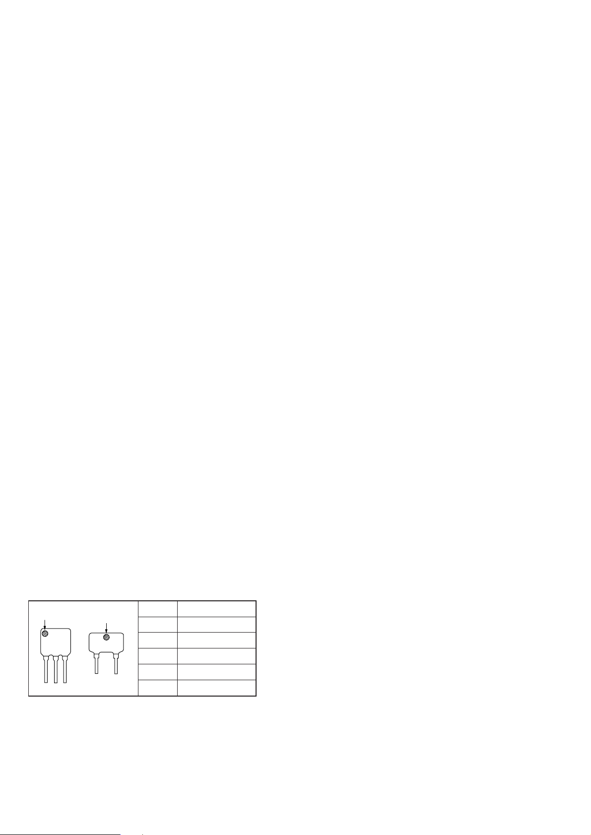
TABLE OF CONTENTS
Specifications ........................................................................... 1
1. GENERAL
Location of Controls .......................................................... 3
2. DIAL POINTER INSTALLATION .........................4
3. DISASSEMBLY
3-1. Cabinet (Front) Assy Removal ................................... 5
3-2. Power Board Removal................................................ 5
3-3. Tuner Board Removal................................................. 6
3-4. Mechanism Deck Removal......................................... 6
3-5. Function Switch Board, Main Volume Board,
MIC Voulem Board Removal ..................................... 7
3-6. Main Board Removal ................................................. 7
4. ADJUSTMENTS
4-1. Mechanical Adjustments ............................................ 8
4-2. Electrical Adjustments................................................ 8
5. DIAGRAMS
5-1. Block Diagrams ........................................................ 12
5-2. Printed Wiring Boards .............................................. 17
5-3. Schematic Diagram................................................... 21
6. EXPLODED VIEWS
6-1. Rear Cabinet Section ................................................ 27
6-2. Front Panel Section................................................... 28
6-3. Mechanism Deck Section (1) ................................... 29
6-4. Mechanism Deck Section (2) ................................... 30
6-5. Speaker Section ........................................................ 31
7. ELECTRICAL PARTS LIST ................................ 32
• HOW TO CHANGED THE CERAMIC FILTERS
This model is used three ceramic filters of CF1, CF2 and CF3.
You must used same type of color marked ceramic filters in
order to meet same specifications.
Therefore, the ceramic filter must changed three pieces together
since it’s supply three pieces in one package as a spare parts.
mark
CF1, 2
mark
CF3
Mark Center Frequency
red 10.70MHz
blue 10.67MHz
orange 10.73MHz
black 10.64MHz
white 10.76MHz
SAFETY-RELATED COMPONENT WARNING!!
COMPONENTS IDENTIFIED BY MARK ! OR DOTTED LINE WITH
MARK !ON THE SCHEMATIC DIAGRAMS AND IN THE PARTS
LIST ARE CRITICAL TO SAFE OPERATION.
REPLACE THESE COMPONENTS WITH SONY PARTS WHOSE
PART NUMBERS APPEAR AS SHOWN IN THIS MANUAL OR IN
SUPPLEMENTS PUBLISHED BY SONY.
– 2 –
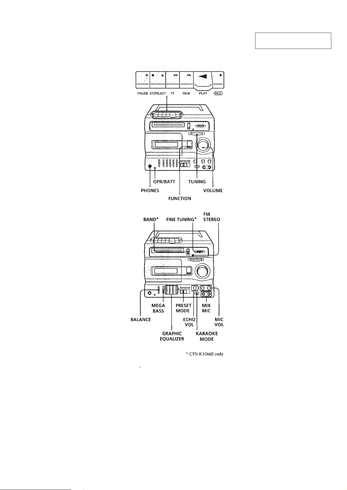
LOCATION OF CONTROLS
SECTION 1
GENERAL
This section is extracted from
instruction manual.
– 3 –
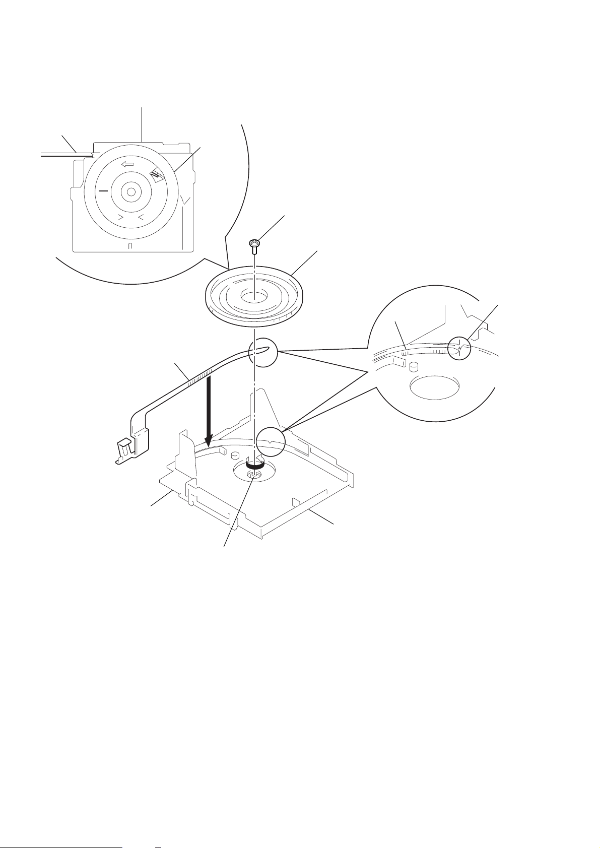
SECTION 2
h
DIAL POINTER INSTALLATION
Note : Follow the installation procedure in the numerical order given.
Chassis
Pointer
MIN
PS
(Fig-2)
Pointer
Knob (tune)
2
5
Screw (+P 2.6x6)
4
Knob (tune)
3
Pointer
Notc
(Fig-1)
Tuner board
PVC shaft
1
Chassis
1
Turn the PVC shaft fully counterclockwise.
2
Place the pointer in the chassis groove.
3
Line up the tip of the pointer with the notch in the chassis.
(Fig-1)
4
Attach so that the knob (Tune) is at the position show in Fig-2.
5
Fasten the knob (tune) to the PVC shaft with the screw.
– 4 –
SECTION 3
1
Screws
(+BV 3x10)
2
Cabinet (rear) assy
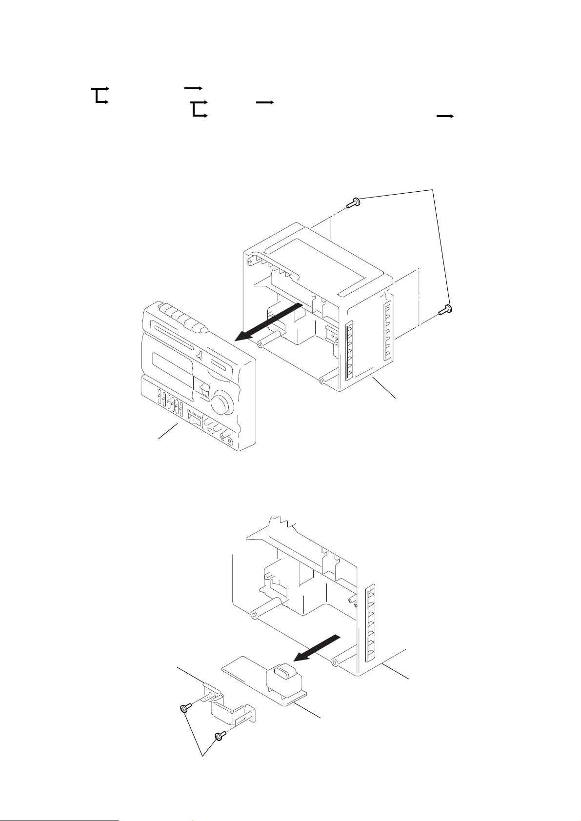
Power board
Bracket (T)
DISASSEMBLY
r
The equipment can be removed using the following procedure.
Set
Cabinet (Rear) assy
Cabinet (Front ) assy
Note : Follow the disassembly procedure in the numerical order given.
3-1. CABINET (FRONT) ASSY REMOVAL
Power board
Tuner board
Mechanism deck
Function switch board, Main volume board, MIC volume board
Main board
1
Screws
(+BVTP 3x14) : CFS-K1066
(+BV 3x14) : CFS-K1066S
Cabinet (front) assy
3-2. POWER BOARD REMOVAL
2
Cabinet (rear) assy
– 5 –
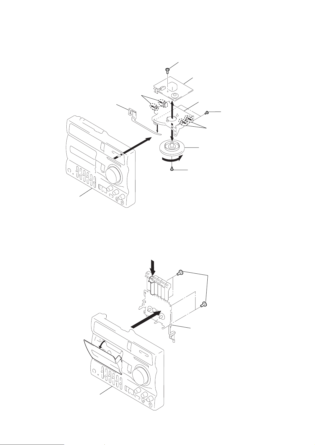
3-3. TUNER BOARD REMOVAL
Pointer
8
Claws
9
7
Screw (+BV 3x8)
Tuner board
Chassis
2
Screws (+BVTP 2.6x8)
Cabinet (front) assy
3-4. MECHANISM DECK REMOVAL
3
6
5
1
STOP/EJECT button
1
4
Screw
(+P 2.6x6)
8
Claws
Knob (TUN)
3
Screws (+BV 3x10)
Cabinet (front) assy
4
Mechanism deck
2
– 6 –
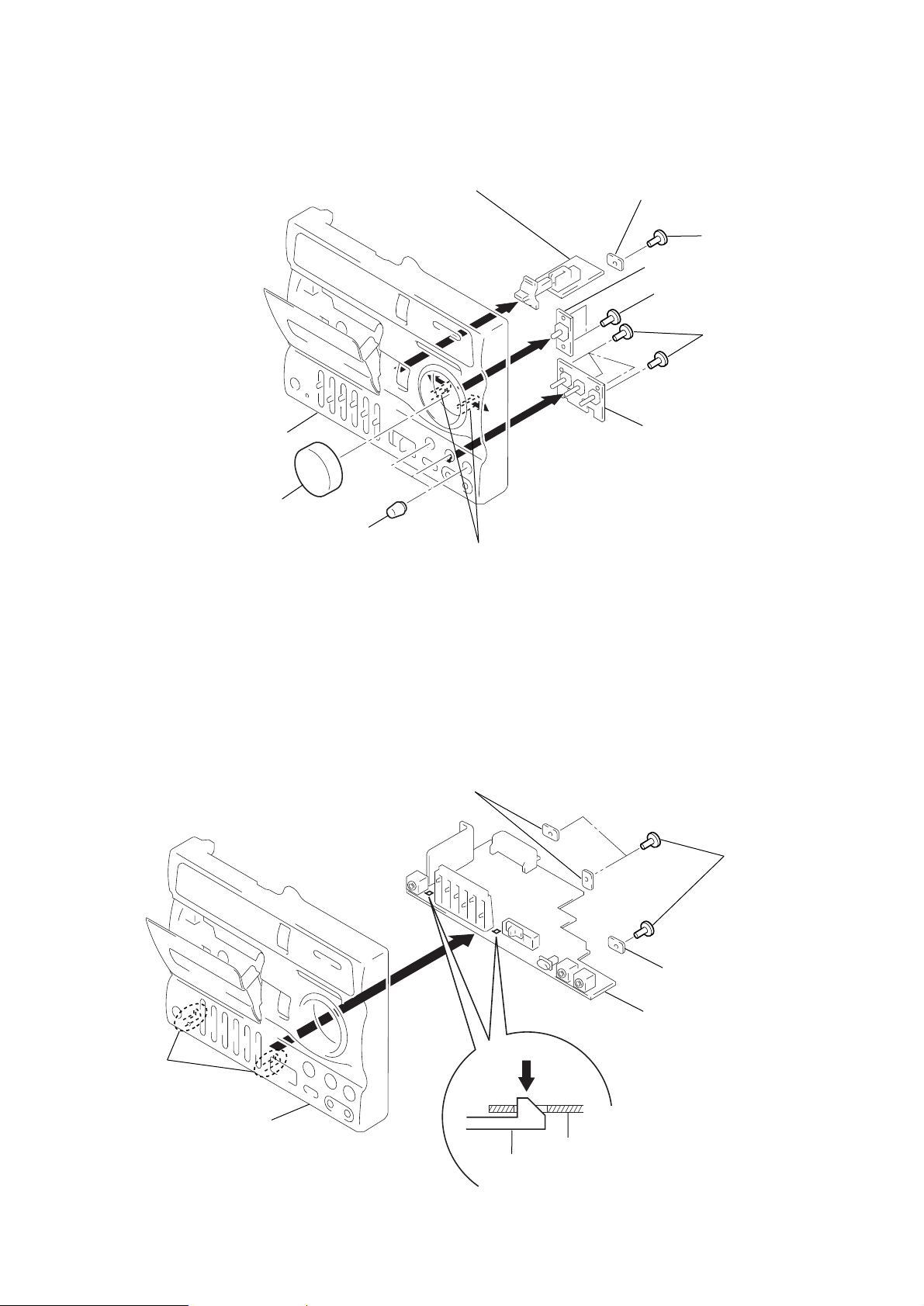
3-5. FUNCTION SWITCH BOARD, MAIN VOLUME BOARD, MIC VOLUME BOARD REMOVAL
)
Cabinet (front) assy
3
Knob (VOL)
4
Knob (MIC)
Function switch board
2
6
Claws
7
9
Retainer board (A)
1
Screw (+BVTP 2.6x8)
Main volume board
5
Screws (+BVTP 2.6x8)
8
Screws (+BVTP 2.6x8
MIC volume board
3-6. MAIN BOARD REMOVAL
Claws
Retainer board (A)
3
2
Retainer board (B)
Main board
1
Screws (+BVTP 2.6x8)
Cabinet (front)
Main board
Claw
– 7 –
 Loading...