

Sony CFSB-7-S Mk2 Service manual
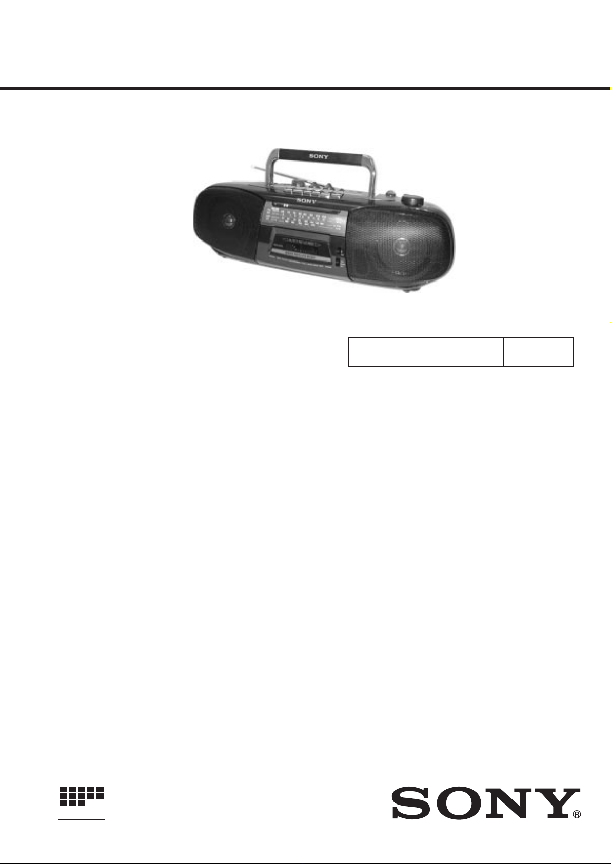
CFS-B7SMK2
SERVICE MANUAL
Ver 1.1 1998. 11
SPECIFICATIONS
Frequency range
FM : Saudi Arabia 87.6 – 107 MHz
Other countries 87.6 – 108 MHz
MW : 530 – 1,605 kHz
SW1 : 2.3 – 7 MHz
SW2 : 7 – 22 MHz
Aerials
FM/SW : Telescopic aerial
MW : Built-in ferrite bar
Recording system
2-track, 4-channel stereo
Frequency response
70 – 10,000 Hz
Speakers
Full range : 10 cm (4 inches) dia,
2.8 ohms cone type × 2
Output
Headphones jack (stereo minijack),
for 16 – 68 ohms impedance headphones
Maximum Power output
2.5 W + 2.5 W
E Model
Model Name Using Similar Mechanism NEW
T ape Tr ansport Mechanism Type MF-B7S-148
Battery life
FM Recording : Sony R20P : Approx.
16 hours/Sony LR20 alkaline :
Approx. 36 hours
Playback : Sony R20P : Approx.
8 hours/Sony LR20 alkaline :
Approx. 21 hours
Power requirements
110 – 120 V/220 – 240 V AC
selectable, 50/60 Hz
Power consumption
AC 14 W
Dimensions
Approx. 500 × 155 × 164 mm (w/h/d)
(193/4 × 61/8 × 61/2 inches) incl.
projecting parts and controls, not incl. handle
Mass
Approx. 2.7 kg (5 lb 15 oz) not incl. batteries
Supplied accessory
Mains lead (1)
Design and specifications are subject to change without
notice.
MICROFILM
RADIO CASSETTE-CORDER

TABLE OF CONTENTS
1. GENERAL
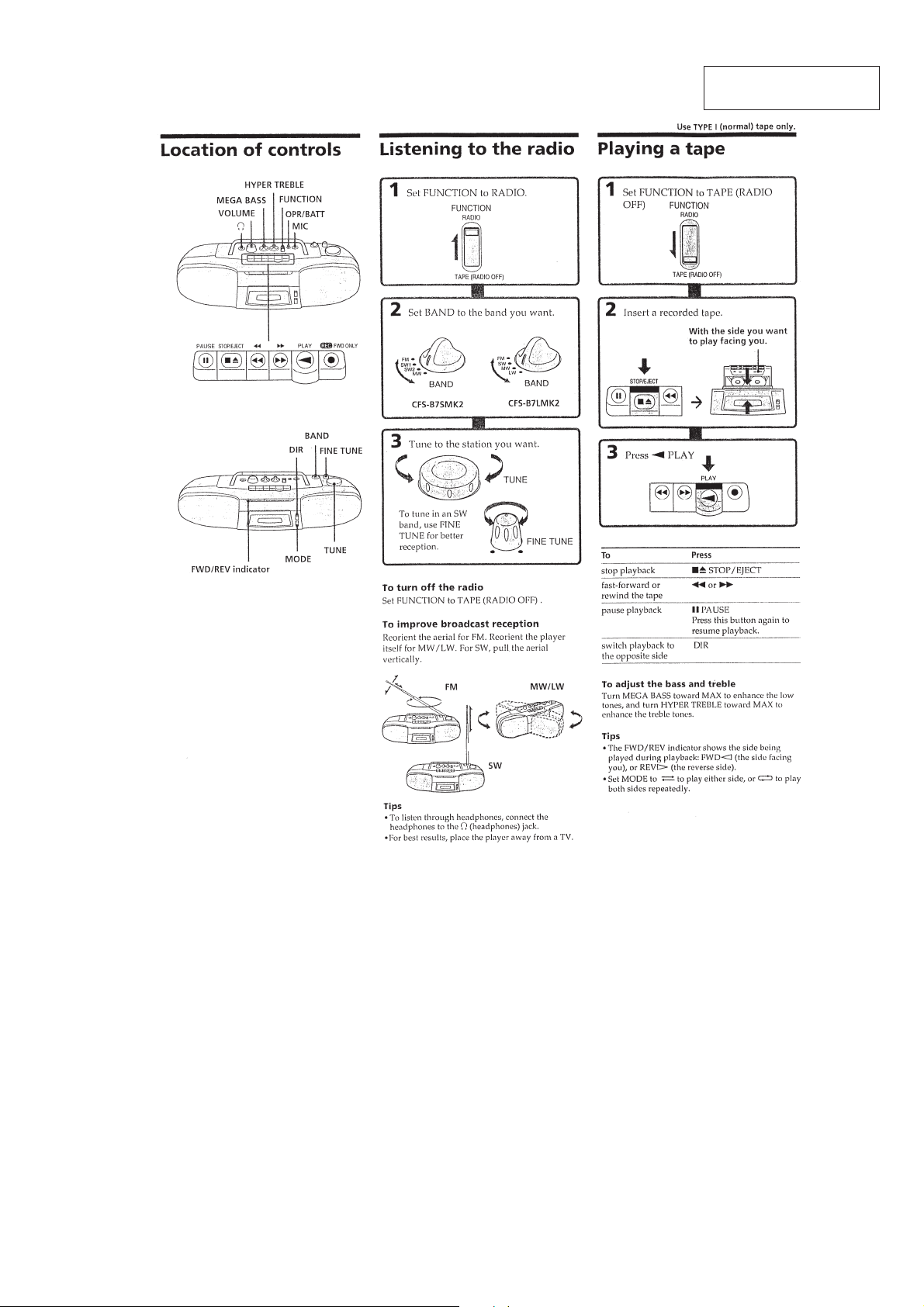
Location of Controls··························································· 3
Listening to the Radio ························································ 3
Playing a Tape ···································································· 3
Recording ··········································································· 4
Choosing Power Sources···················································· 4
2. DISASSEMBLY
2-1. Front Cabinet Assy ····························································· 5
2-2. Chassis (Tune) ···································································· 5
2-3. Tape Mechanism Block ······················································ 6
2-4. Tuner, AC, Second Board ···················································6
2-5. Audio, Mic Board······························································· 7
2-6. Dial Pointer Setting ···························································· 7
3. MECHANICAL ADJUSTMENTS···························· 8
4. ELECTRICAL ADJUSTMENTS
4-1. Tape Section ······································································· 8
4-2. Tuner Section······································································ 9
5. DIAGRAMS
5-1. Circuit Boards Location ··················································· 11
5-2. Printed Wiring Board —Tuner Section — ······················· 12
5-3. Schematic Diagram —Tuner Section —·························· 13
5-4. Schematic Diagram — Audio Section —························· 15
5-5. Printed Wiring Board — Audio Section —····················· 17
6. EXPLODED VIEWS
6-1. Front Cabinet Section ······················································· 19
6-2. Rear Cabinet Section ························································ 20
6-3. Mechanism Deck Section (1) ··········································· 21
6-4. Mechanism Deck Section (2) ··········································· 22
6-5. Mechanism Deck Section (3) ··········································· 23
6-6. Mechanism Deck Section (4) ··········································· 24
7. ELECTRICAL PARTS LIST··································· 25
SAFETY-RELATED COMPONENT WARNING!!
COMPONENTS IDENTIFIED BY MARK ! OR DOTTED LINE WITH
MARK ! ON THE SCHEMATIC DIAGRAMS AND IN THE PARTS
LIST ARE CRITICAL TO SAFE OPERATION. REPLACE THESE
COMPONENTS WITH SONY PARTS WHOSE PART NUMBERS
APPEAR AS SHOWN IN THIS MANUAL OR IN SUPPLEMENTS
PUBLISHED BY SONY .
— 2 —
SECTION 1
GENERAL
This section is extracted
from instruction manual.
— 3 —
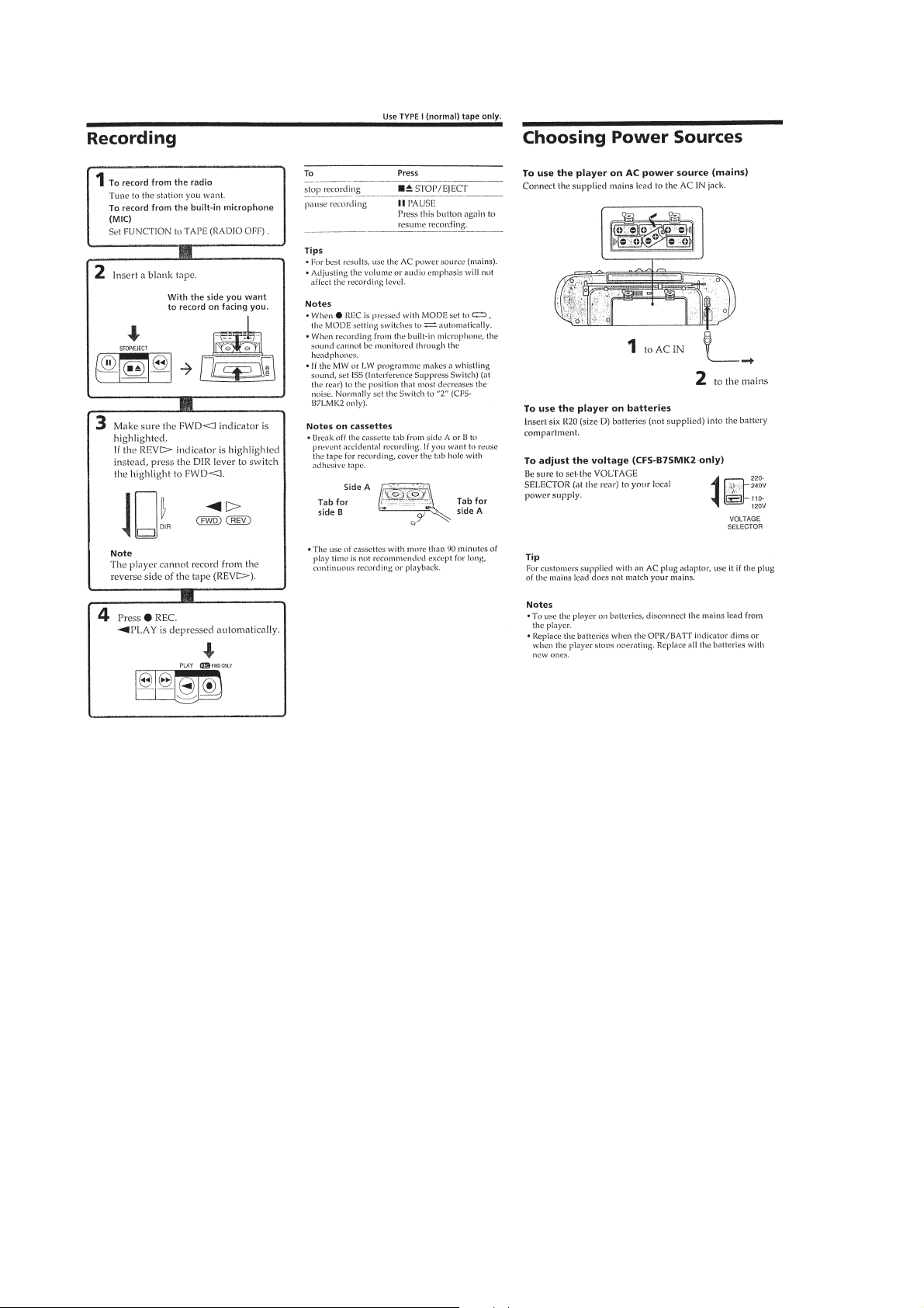
— 4 —
SECTION 2
• The equipment can be removed using the following procedure.
Set / Front cabinet assy / Chassis (TUNE) / Tape mechanism block / Tuner, AC, Second board /
Audio, Mic board
DISASSEMBLY
Note : Follow the disassembly procedure in the numerical order given.
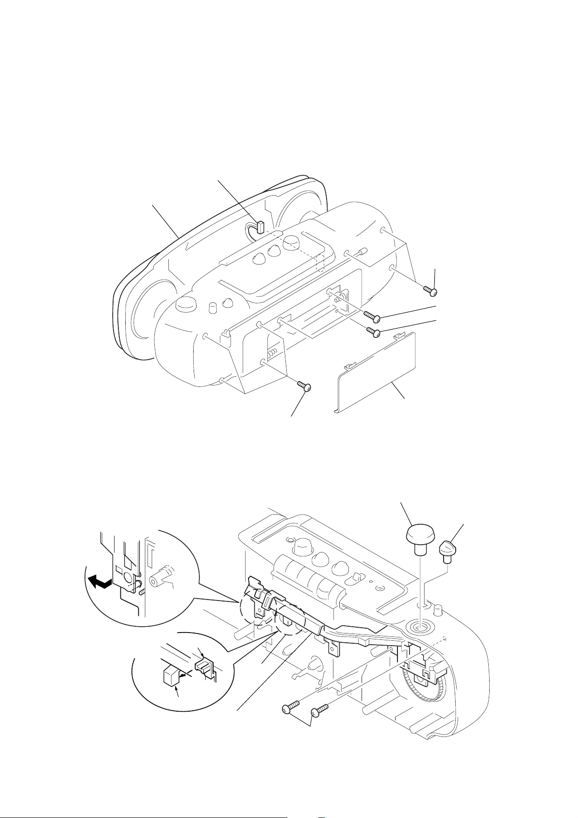
2-1. FRONT CABINET ASSY
6
CN912
7
front cabinet assy
4
BVTP 3
3
BVTP 3
2
BVTP 3
×
12
×
×
16
12
2-2. CHASSIS (TUNE)
Fig. A
Fig. B
slider, D
5
indicator
BVTP 3
×
12
1
lid, battery case
1
knob (TUNE)
2
knob (BAND)
indicator
4
Note : Be careful when removing
as it is engaged as shown
in Fig. A and Fig. B.
chassis (TUNE)
3
BVTP 3
— 5 —
×
10
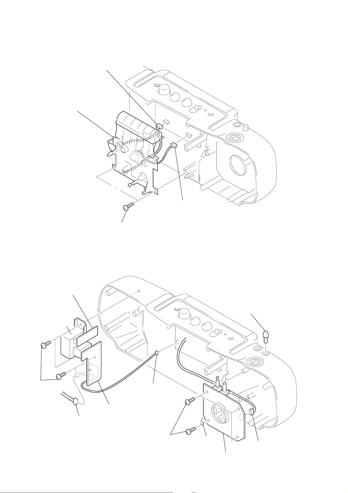
2-3. TAPE MECHANISM BLOCK
3
CN601
4
tape mechanism block
2
CN301
1
BVTP 3
×
10
2-4. “ TUNER BOARD ”, “ AC BOARD ”, “ SECOND BOARD ”
0
SECOND board
8
T901
7
BVTP 3 × 10
5
CN911
1
knob (FINE TUNE)
6
CN901
9
AC board
2
BVTP 3 × 10
— 6 —
TERMINAL,
ANTENNA
4
TUNER board
3
CN1
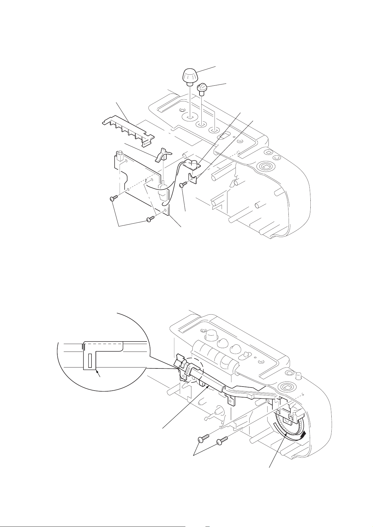
2-5. “ AUDIO BOARD ”, “ MIC BOARD ”
3
chassis (MD)
9
lever (FUNCTION)
7
BVTP 3 × 10
4
BVTP 3x10
8
AUDIO board
1
knob (VOLUME)
2
knob
(HYPER TREBLE/MEGA BASS)
6
MIC board
5
SUPPORT board
2-6. DIAL POINTER SETTING
2
Set the pointer to the
center of three vertical lines.
pointer
3
Set the chassis (TUNE).
4
BVTP 3 × 10
— 7 —
1
Turn the VC drum in the direction
of the allow to its end.
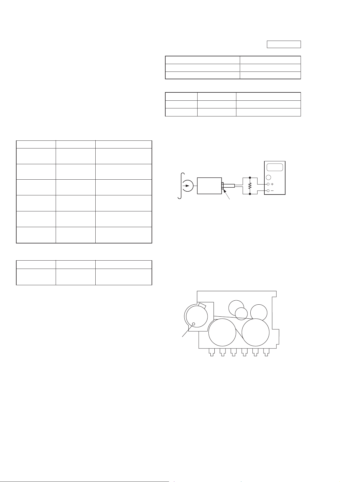
SECTION 3
MECHANICAL ADJUSTMENTS
SECTION 4
ELECTRICAL ADJUSTMENTS
PRECAUTION
1. Clean the following parts with a denatured alchool-moistened
swab:
record/playback head pinch roller
erase head rubber belts
capstan idlers
2. Demagnetize the record/playback head with a head
demagnetizer. (Do not bring the head demagnetizer close to the
erase head.)
3. Do not use a magnetized screwdriver for the adjustments.
4. After the adjustments, apply suitable locking compound to the
parts adjusted.
5. The adjustments should be perfomed with the rated power supply
voltage unless otherwise noted.
Torque Measurement
Mode
Forward
Forward
back tension
REV
REV
back Tension
Fast
Forward
Rewind
T ape Tension Measurement
Mode
Forward
Torque Meter
CQ-102C
CQ-102C
CQ-102C
CQ-102C
CQ-201B
CQ-201B
Torque Meter
CQ-403A
Meter Reading
25 – 60 g•cm
(0.35 – 0.83 oz•inch)
1 – 5 g•cm
(0.014 – 0.069 oz•inch)
25 – 60 g•cm
(0.35 – 0.83 oz•inch)
1 – 5 g•cm
(0.014 – 0.069 oz•inch
55 – 140 g•cm
(0.76 – 1.94 oz•inch)
55 – 140 g•cm
(0.76 – 1.94 oz•inch)
Meter Reading
more than 170 g
(more than6.00 oz)
4-1. TAPE SECTION
Standard output level
Output terminal
Load impedance
Output signal level
Test tape
T est Tape
WS-48B
P-4-A063
Tape Speed Adjustment
Procedure :
Mode : Playback
test tape
WS-48B
(3 kHz, 0 dB)
1. Playback the test tape in the FWD playback mode.
2. Confirm that the digital frequency counter reading indicates a
value in the range of 2,940 to 3,060 Hz at tape top.
3. If the specification is not satisfied, adjust variable resistor of
motor (M901) until the frequency counter reading is as close to
3,000 Hz as possible at the FWD tape top.
Specification : 2,940 to 3,060 Hz
4. Frequency difference between the beginning and the end of the
tape should be within 1.5% (45Hz).
Adjustment Location :
Signal
3kHz, 0dB
6.3 kHz, -10 dB
set
phones jack
tape speed adjustment
head azimuth adjustment
32
Ω
0dB = 0.775V
HP OUT
32 Ω
0.25 V (–10 dB)
Used for
digital frequency
counter
0000
— 8 —
TAPE
SPEED
ADJ.
(M901)
 Loading...