

Sony CFSB-21-L Service manual
CFS-B21L
SERVICE MANUAL
Ver 1.0 1999. 06
With SUPPLEMENT-1 (9-923-272-81)
SPECIFICATIONS
Frequency range FM : 87.6–107 MHz
MW : 531–1,602 kHz
L W : 153–279 kHz
IF FM : 10.7 MHz
MW/LW : 455 kHz
Aerials FM : Telescopic
MW/LW : Built-in ferrite bar
Recording system 4-track, 2-channel stereo
Frequency response 100-10,000Hz
Speakers Full-range : 10cm (4 inches) dia.×2,
cone type
Output Headphones jack (stereo minijack), for
16 to 68 ohms impedance headphones
Maximum power output 2.0W+2.0W
Battery life FM Recording : Sony R20P : Approx.
9 hours/Sony alkaline LR20 : Approx.
21 hours
Playback : Sony R20P : Approx.
6 hours/Sony alkaline LR20 : Approx.
13 hours
AEP Model
UK Model
Model Name Using Similar Mechanism CFS-B15
Tape Transport Mechanism Type MF-B15-117
Power requirements 230V AC, 50Hz
6V DC, four R20 (size D) batteries
Power consumption AC 13W
Dimensions Approx. 422×140×136mm (w/h/d)
(165/8 × 55/8 × 53/8 inches) incl.
projecting parts and controls
Mass Approx. 1.9kg (4lb 3 oz) incl.
batteries
Supplied accessory Mains lead (1)
Design and specifications are subject to change without notice.
MICROFILM
RADIO CASSETTE-CORDER

TABLE OF CONTENTS
1. GENERAL ··································································· 3
2. DISASSEMBLY
2-1. Removal of Front Cabinet ··············································· 4
2-2. Removal of Mechanism Deck ········································· 4
2-3. Dial Pointer Setting ························································· 5
3. MECHANICAL ADJUSTMENTS························· 6
4. ELECTRICAL ADJUSTMENTS
4-1. Tape Recoder Section······················································ 6
4-2. Radio Section ·································································· 7
5. DIAGRAMS
5-1. Circuit Board Location ···················································· 9
5-2. IC Block Diagrams ·························································· 10
5-3. Printed Wiring Board – Main Section – ·························· 11
5-4. Schematic Diagram – Main Section – ····························· 13
5-5. Printed Wiring Board and Schematic Diagram
– Tuner Section –····························································· 16
6. EXPLODED VIEWS
6-1. Front Cabinet Section ······················································ 19
6-2. Rear Cabinet Section ·······················································20
6-3. Mechanism Deck Section (1) ·········································· 21
6-4. Mechanism Deck Section (2) ·········································· 22
7. ELECTRICAL PARTS LIST ·································· 23
SAFETY-RELATED COMPONENT WARNING!!
COMPONENTS IDENTIFIED BY MARK ! OR DOTTED LINE WITH
MARK ! ON THE SCHEMATIC DIAGRAMS AND IN THE PARTS
LIST ARE CRITICAL TO SAFE OPERATION. REPLACE THESE
COMPONENTS WITH SONY PARTS WHOSE PART NUMBERS
APPEAR AS SHOWN IN THIS MANUAL OR IN SUPPLEMENTS
PUBLISHED BY SONY.
— 2 —
SECTION 1
GENERAL
1
2
4
3
!¡ !™ !£ !¢ !∞ !§
5
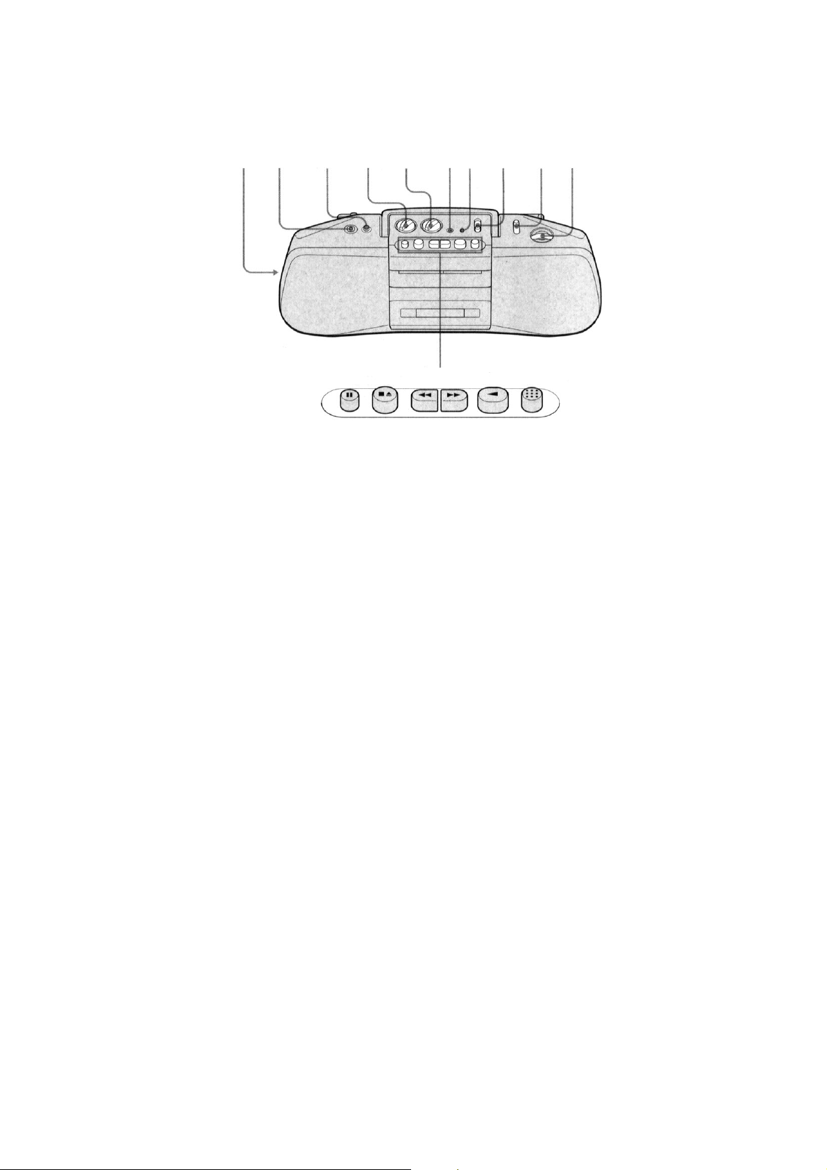
1 FM MODE/ISS switch
2 2 (phones) jack
3 MEGA BASS button
4 VOLUME knob
5 TONE knob
6 MIC
7 ORP/BATT indicator
8 FUNCTION switch
9 BAND switch
!º TUNING knob
!¡ PAUSE button
!™ STOP/EJECT button
!£ FF button
!¢ REW button
!∞ PLAY button
!§ REC button
6
7
8
9
!º
— 3 —
SECTION 2
4
DISASSEMBLY
• The equipment can be removed using the following procedure.
Front cabinet Mechanism Deck Main board Volume board
Retainer board Dial Pointer Bracket Power board
Battery board
Tuner board
Note : Follow the disassembly procedure in the numerical order given.
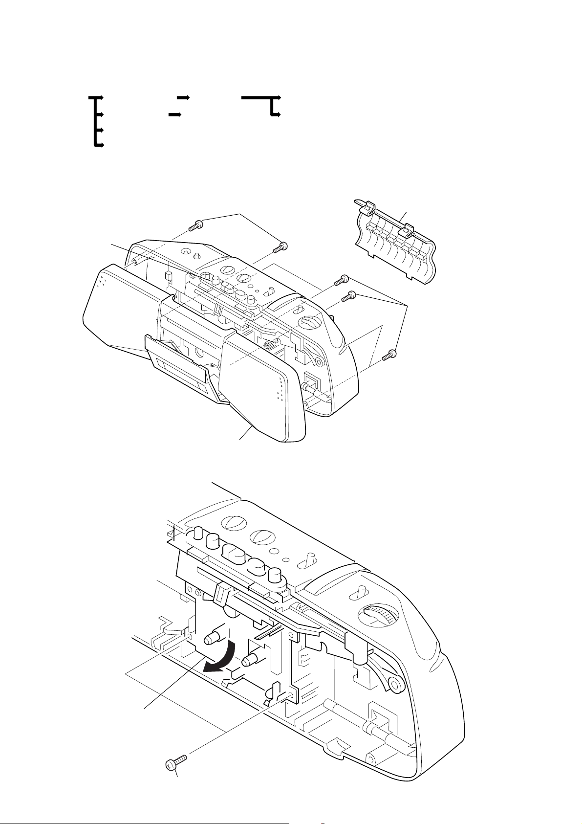
2-1. REMOVAL OF FRONT CABINET
3
+BVTP 3 × 14
4
Push the
EJECT button
1
battery case lid
2
+BVTP 3 × 1
2-2. REMOVAL OF MECHANISM DECK
2
Remove the mechanism deck
in the direction of the arrow.
5
front cabinet
1
+BVTP 3 × 10
— 4 —
SECTION 3
a
color code
CF1
)
)
a
frequency
counter
1
µ
F
33k
Ω
MECHANICAL ADJUSTMENTS
SECTION 4
ELECTRICAL ADJUSTMENTS
2-3. DIAL POINTER SETTING
stopper
(stopper is a part of
dial pointer bracket,
and located at the
left end.)
2
Insert the pointer into stopper
and set for tuning knob.
1
Turn tuning knob fully in the
direction of the arrow.
PRECAUTION
1. Clean the following parts with a denatured-alcohol moistened
swab :
record/playback head pinch roller
erase head rubber belts
capstan idlers
2. Demagnetize the record/playback head with a head
demagnetizer. (Do not bring the head demagnetizer close to
the erase head.)
3. Do not use a magnetizer screwdriver for the adjustments.
4. After the adjustments, apply suitable locking compound to
the parts adjusted.
5. The adjustment should be perfomed with the reted power
supply voltage unless otherwise noted.
6. Power supply voltage: 6V dc.
Torque Measurement
Torque
Forward
Forward
back tension
Fast
Forward
Rewind
Torque meter
CQ-102C
CQ-102C
CQ-201B
CQ-201B
Meter reading
30-70g•cm
(0.42-0.97 oz•inch)
1.5-5.5g•cm
(0.020-0.076 oz•inch)
more than 60g•cm
(more than 0.83 oz•inch)
more than 60g•cm
(more than 0.83 oz•inch)
Tape Tension Measurement
Torque meter
Meter reading
more than 100g
CQ-403A
(more than 3.53 oz)
4-1. TAPE RECODER SECTION
Standard Output Level
output terminal
load impedance
output signal level
T est Tape
Type
WS-48A
P-4-A063J
6.3kHz, –10dB
Tape Speed Adjustment
Procedure :
Mode : playback
test tape
WS-48A
(3kHz, 0dB)
set
Adjustment Value :
Speed checker
–1% to +1%
Frequency difference between the beginning and the end of the tape
should be within 1.5% (45Hz).
Adjustment Location :
HP OUT
0.25V (–10dB)
Signal
3kHz, 0dB
phones jack
SP OUT
32
12
0dB
Used for
tape speed adjustment
head azimuth adjustment
speed checker
LFM-30
or
digital frequency
counter
32k
Ω
Digital frequency counter
2,970–3,030Hz
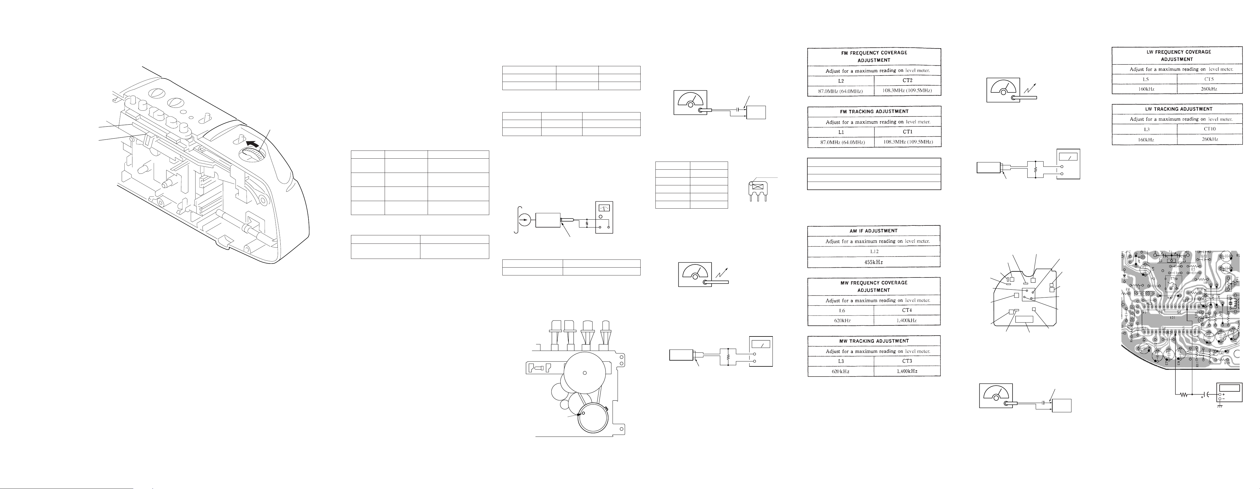
4-2. RADIO SECTION
• FM Section
Setting :
FUNCTION switch : RADIO
BAND switch : FM
FM RF signal
generator
22.5kHz frequency
deviation by 400Hz signal
output level : as low as possible
* : The FM IF adjustment specifications are different depending
upon the color code of CF1. See the following table.
CF1 color
Red
Blue
Orange
Black
White
frequency
10.70MHz
10.67MHz
10.73MHz
10.64MHz
10.76MHz
• MW Section
Setting :
FUNCTION switch : RADIO
BAND switch : MW
AM RF signal
generator
30% amplitude
modulation by
400Hz signal
output level : as low as possible
telescopic antenn
input
0.01
µ
F
set
Put the lead-wire
antenna close to
the set.
( ) : EE1 model
Adjust for a maximum reading on level meter.
FM IF ADJUSTMENT
L4
*
• LW Section
FUNCTION switch : RADIO
BAND switch : LW
AM RF signal
generator
30% amplitude
modulation by
400Hz signal
output level : as low as possible
set
phones jack
Put the lead-wire
antenna close to
the set.
32
Ω
level meter
(range : 0.5–5V ac
+
–
• Repeat the procedures in each adjustment several times, and
the frequency coverage and tracking adjustments should be
finally done by the trimmer capacitors.
Adjustment Location : TUNER BOARD (COMPONENT SIDE)
L6 : MW FREQUENCY
COVERAGE
CT4 : MW FREQUENCY
COVERAGE
CT5 : LW FREQUENCY
COVERAGE
L5 : LW FREQUENCY
COVERAGE
CT3 : MW TRACKING
CT2 : FM FREQUENCY
COVERAGE
CF1
CT1 : FM
TRACKING
L2 : FM
FREQUENCY
COVERAGE
L1 : FM
TRACKING
L12 : AM IF
CF2
Adjustment Location :
[TUNER BOARD] (conductor side)
level meter
(range : 0.5–5V ac
32
Ω
set
phones jack
tape speed adjustment
control inside motor
— 5 —
— 6 — — 7 — — 8 —
+
–
L4 : FM IF
RV1 : FM VCO
L3 : MW TRACKING,
LW TRACKING
CT10 : LW TRACKING
FM VCO Adjustment
Procedure :
FM RF signal
generator
Carrier frequency : 98MHz
Modulation : no modulation
Output level : 0.1V (100dB)
telescopic antenn
input terminal
0.01
µ
F
set
1. Connect frequency counter as shown below.
2. Tune the set to 98MHz.
3. Adjust RV1 for 76kHz±50Hz reading on the frequency counter .
CFS-B21L
5-1. CIRCUIT BOARDS LOCATION
MAIN board
SECTION 5
DIAGRAMS
BATTERY board
VOLUME board
RETAINER board
TUNER board
5-2. IC BLOCK DIAGRAMS
• IC1 CXA1238S
GND
PLL LPF2
30 29
VCO MPX REG.
MONO/ST
MPX REG
VCOFMDISCRI
28 27 26 25 24 23 22 21 20 19 18 17 16
SELECT
MUTE
AM OSC
1/2
COUNTER
1/2
COUNTER
MUTING
DECODER AMP
AFC
FM OSC
REG
REG
PD1
PD2
AUTOBLEND
RIPPLE
FILTER
FM RF
AM RF IN
FM FRONT-END
AM FRONT-END
BAND PASS
MUTE
FM RF IN
INDICATOR
FM IF/
DISCRI
AM
IF/DET
TUNING
FM GND
FM/AM
FE OUT
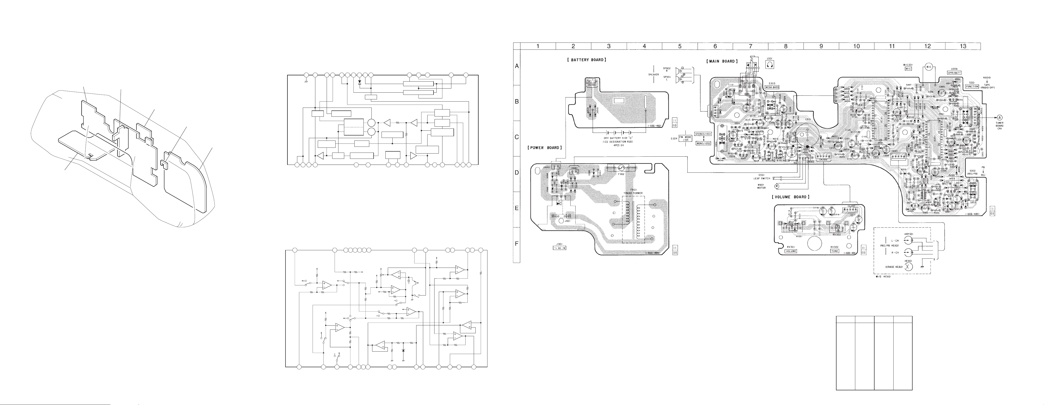
5-3. PRINTED WIRING BOARD — MAIN SECTION —
POWER board
4 5 6 7 8 9 10 11 12 13 14 15321
PLL LPF1
ST IND/
VCO CHECK
PILOT DET LPF2
PILOT DET LPF2
• IC101,201 MM1315BD
MIC-IN
30
B+
B+
VCC
FILTER
L CH OUT
R CH OUT
AUX-INSWSWSWNCNCSW
29 28 27 26 25 24 23 22 21 20 19 18 17 16
B+
B+
B+
B+
B+
RIPPLE
AGC AFC1
LPF-2
B+
AGC AFC2
ALC
GND
B+
TUNE IND
POP-NOISE-DEL
POWER GND
FM IF IN
AM IF IN
BAND SELECT
POWER-OUT-A
VCC
S VCC
B+
B+
B+
B+
1
MIC IN (–)
2
HEAD-IN (+)
3 4 5 7 8 9 10 11 12 13 14 156
PRE
PRE-IN
HEAD-IN (–)
VBIAS2
VBIAS1
— 9 — — 10 —
B+
NC
SIG-GND
R-VCC
LIN-OUT
POWER IN
RIP-FIL
POWER GND
• Semiconductor Location
Ref. No. Location
D301 E-13
D304 C-7
D305 C-7
D306 A-13
D307 C-7
D308 C-7
D309 D-11
D901 D-2
D902 D-1
D903 D-3
D904 D-1
IC101 C-11
POWER-OUT-B
IC201 C-12
Ref. No. Location
Q101 C-7
Q102 C-8
Q201 C-7
Q202 C-8
Q301 E-12
Q303 D-13
Q304 C-13
Q305 C-13
Q306 B-13
Q307 E-12
Q308 C-7
Note:
• X : parts extracted from the component side.
• W : indicates side identified with part number.
— 11 — — 12 —
 Loading...