

SONY CFD G555CP Service Manual
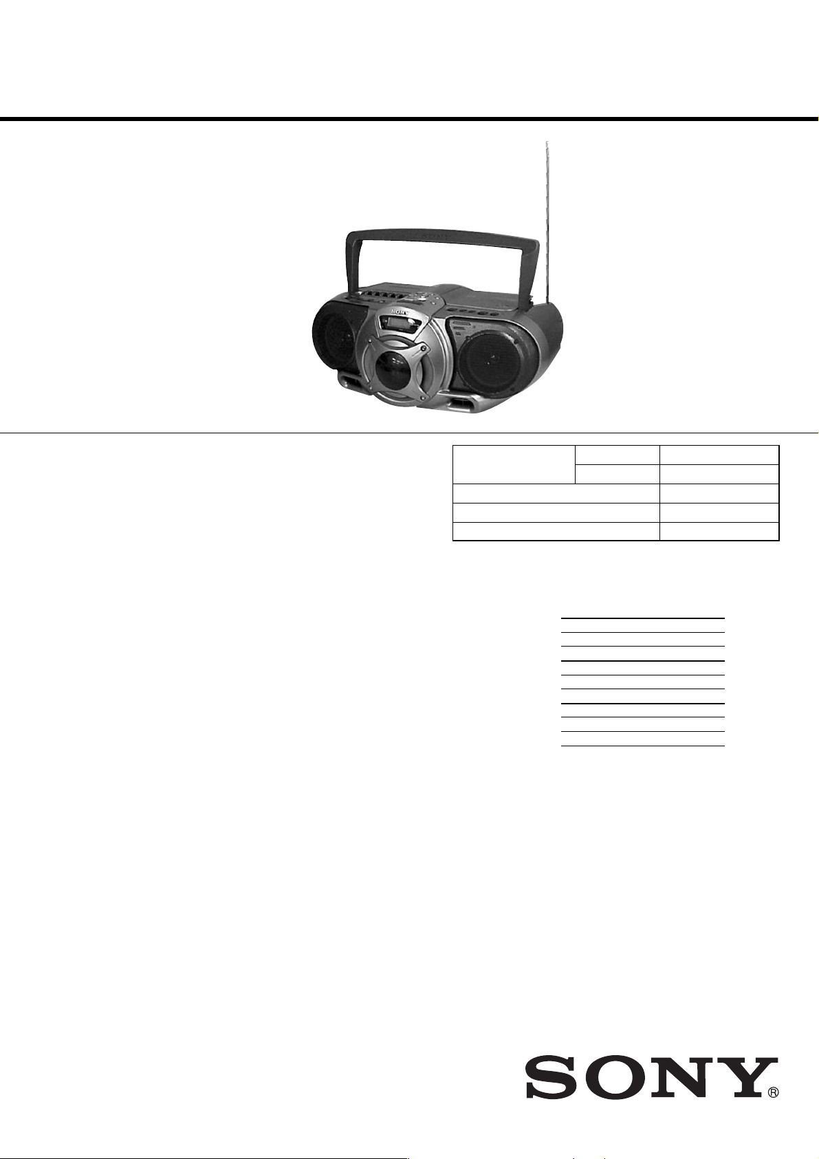
CFD-G55
SERVICE MANUAL
Ver 1.2 2002. 07
SPECIFICATIONS
AUDIO POWER SPECIFICATIONS
POWER OUTPUT AND TOTAL
HARMONIC DISTORTION
With 3.2-ohm loads, both channels driven
from 1 000 - 10 000 Hz; rated 3 W per
channel-minimum RMS power, with no
more than 10 % total harmonic distortion
in AC operation.
Woofer with 4-ohm loads, driven at
50 - 150 Hz; rated 6 W minimum RMS
power, with no more 10 % total harmonic
distortion in AC operation.
Other specifications
CD player section
System
Compact disc digital audio system
Laser diode properties
Material: GaAlAs
Wave length: 780 nm
Emission duration: Continuous
Laser output: Less than 44.6 µW
(This output is the value measured at a distance
of about 200 mm from the objective lens surface
on the optical pick-up block with 7 mm
aperture.)
Spindle speed
200 r/min (rpm) to 500 r/min (rpm)
(CLV)
Number of channels
2
Frequency response
20 - 20 000 Hz +1/–2 dB
Wow and flutter
Below measurable limit
Radio section
Frequency range
FM : 87.5 - 108 MHz
AM: 530 - 1 710 kHz (Other models)
: 531 - 1 611 kHz (9 kHz Step)
530 - 1 610 kHz (10 kHz Step)
(MY, SP, EA models)
IF
FM : 10.7 MHz
AM: 450 kHz
Antennas
FM: Telescopic antenna
AM: Built-in ferrite bar antenna
Cassette-corder section
Recording system
4-track 2 channel stereo
Fast winding time
Approx. 115 s (sec.) with Sony cassette C-60
Frequency response
TYPE I (normal): 70 - 13 000 Hz
General
Speaker
Full range: 10 cm (4
(2)
Woofer: 8 cm (3
Outputs
Headphones jack (stereo minijack)
For 16 - 68 Ω impedance headphones
Power output
4 W + 4 W (at 3.2 Ω, 10% harmonic distortion
in DC operation)
Woofer:
12 W (at 4 Ω, 10 % harmonic distortion in DC
operation)
Power requirements
For CD radio cassette-corder:
120V AC, 60 Hz (Other models)
110-127V, 220-240V AC
Selectable, 60Hz (EA model)
230V AC, 50Hz (MY, SP models)
12 V DC, 8 size D (R20) batteries
For remote control:
3 V DC, 2 size AA (R6) batteries
in.) dia., 3.2 Ω
1
⁄
in.) dia., 4 Ω, cone type (1)
4
US Model
Canadian Model
E Model
Model Name Using
Similar Mechanism
CD Mechanism Type KSM-213RDP
Optical Pick-up Type KSS-213R
Tape Transport Mechanism Type MF-V5-117
, cone type
CD Section NEW
Tape Section CFD-G50
Power consumption
AC 30 W
Battery life
For CD radio cassette-corder:
FM recording
Sony R20P: approx. 6 h
Sony alkaline LR20: approx. 18 h
Tape playback
Sony R20P: approx. 1.5 h
Sony alkaline LR20: approx. 6 h
CD playback
Sony R20P: approx. 1 h
Sony alkaline LR20: approx. 4 h
Dimensions
Approx. 456 × 195 × 330 mm (w/h/d)
3
(18 × 7
⁄4 × 13 inches) (incl. projecting parts)
Mass
Approx. 6.8 kg (14 lb. 16 oz) (incl. batteries)
Supplied accessory
AC power cord (1)
Remote control (1)
Design and specifications are subject to change
without notice.
• Abbreviation
EA : Saudi Arabia model.
MY : Malaysia model.
SP : Singapore model.
CD RADIO CASSETTE-CORDER
9-873-639-03
2002G1600-1
© 2002.07
Sony Corporation
Personal Audio Company
Published by Sony Engineering Corporation

CFD-G55
Ver 1.1 2002.05
Notes on chip component replacement
•Never reuse a disconnected chip component.
• Notice that the minus side of a tantalum capacitor may be
damaged by heat.
Flexible Circuit Board Repairing
•Keep the temperature of soldering iron around 270˚C
during repairing.
• Do not touch the soldering iron on the same conductor of the
circuit board (within 3 times).
• Be careful not to apply force on the conductor when soldering
or unsoldering.
TABLE OF CONTENTS
1. SERVICING NOTES ······················································ 3
2. GENERAL ·········································································· 4
3. DISASSEMBLY ································································ 5
3-1. Cabinet (Front) Assy- 1················································· 5
3-2. Cabinet (Front) Assy- 2················································· 6
3-3. CONTROL (POWER), CONTROL (CD),
HEADPHONE Board ··················································· 6
3-4. Panel Assy ····································································· 7
3-5. LCD Board, Panel (Upper) ··········································· 7
3-6. Panel (Upper) Assy- 1 ··················································· 8
3-7. Panel (Upper) Assy- 2 ··················································· 8
3-8. POWER, TRANS, VOL SEL Board····························· 9
3-9. TUNER Board, Duct (Upper, Lower)··························· 9
3-10. BATT COM, BATT Board ·········································· 10
3-11. MAIN Board- 1 ··························································· 10
3-12. MAIN Board- 2 ··························································· 11
3-13. Mechanism Deck Section (MF-V5-117) ···················· 11
3-14. CD Block Section (KSM-213RDP) ···························· 12
3-15. PDW, L-R/REG Board ················································ 12
SAFETY-RELATED COMPONENT WARNING!!
COMPONENTS IDENTIFIED BY MARK 0 OR DOTTED LINE WITH
MARK 0 ON THE SCHEMATIC DIAGRAMS AND IN THE PARTS
LIST ARE CRITICAL TO SAFE OPERATION. REPLACE THESE
COMPONENTS WITH SONY PARTS WHOSE PART NUMBERS
APPEAR AS SHOWN IN THIS MANUAL OR IN SUPPLEMENTS
PUBLISHED BY SONY.
4. ADJUSTMENTS ···························································· 13
4-1. Mechanical Adjustments ············································· 13
4-2. Electrical Adjustments ················································ 13
5. DIAGRAMS······································································ 17
5-1. Circuit Boards Location ··············································17
5-2. Block Diagrams ·························································· 18
MAIN Section ····························································· 18
TUNER/CD Section ··················································· 19
5-3. Printed Wiring Board – TUNER Section –················ 20
5-4. Schematic Diagram – TUNER Section – ··················· 21
5-5. Printed Wiring Board – CD Section – ························ 22
5-6. Schematic Diagram – CD Section – ··························· 23
5-7. Printed Wiring Board – TC Section – ························· 24
5-8. Schematic Diagram – TC Section – ····························24
5-9. Printed Wiring Board – MAIN Section – ··················· 25
5-10. Schematic Diagram – MAIN Section (1/2) – ············· 26
5-11. Schematic Diagram – MAIN Section (2/2) – ············· 27
5-12. Printed Wiring Board – AMP Section –······················ 28
5-13. Schematic Diagram – AMP Section – ························ 29
5-14. Printed Wiring Board – CONTROL Section – ··········· 30
5-15. Schematic Diagram – CONTROL Section – ·············· 31
5-16. Printed Wiring Board – POWER Section – ················ 32
5-17. Schematic Diagram – POWER Section – ··················· 33
5-18. IC Pin Function Description ······································· 36
6. EXPLODED VIEWS ······················································ 38
6-1. Cabinet (Front) Section ··············································· 38
6-2. Cabinet (Rear) Section ················································39
6-3. Cabinet (Upper) Section ············································· 40
6-4. Mechanism Deck Section- 1 (MF-V5-117) ················ 41
6-5. Mechanism Deck Section- 2 (MF-V5-117) ················ 42
6-6. CD Mechanism Section (KSM-213RDP) ··················· 43
7. ELECTRICAL PARTS LIST······································· 44
ATTENTION AU COMPOSANT AYANT RAPPORT
LES COMPOSANTS IDENTIFÉS P AR UNE MARQUE 0 SUR LES
DIAGRAMMES SCHÉMA TIQUES ET LA LISTE DES PIÈCES SONT
CRITIQUES POUR LA SÉCURITÉ DE FONCTIONNEMENT. NE
REMPLACER CES COMPOSANTS QUE PAR DES PIÈSES SONY
DONT LES NUMÉROS SONT DONNÉS DANS CE MANUEL OU
DANS LES SUPPÉMENTS PUBLIÉS PAR SONY.
À LA SÉCURITÉ!
2
SECTION 1
SERVICING NOTES
CFD-G55
SAFETY CHECK-OUT
After correcting the original service problem, perform the
following safety checks before releasing the set to the customer:
Check the antenna terminals, metal trim, “metallized” knobs, screws,
and all other exposed metal parts for AC leakage. Check leakage as
described below.
LEAKAGE
The AC leakage from any exposed metal part to earth ground
and from all exposed metal parts to any exposed metal part having
a return to chassis, must not exceed 0.5 mA (500 microamperes).
Leakage current can be measured by any one of three methods.
1. A commercial leakage tester, such as the Simpson 229 or RCA
WT-540A. Follow the manufacturers’ instructions to use these
instruments.
2. A battery-operated AC milliammeter. The Data Precision 245
digital multimeter is suitable for this job.
3. Measuring the voltage drop across a resistor by means of a
VOM or battery-operated AC voltmeter. The “limit” indication
is 0.75 V, so analog meters must have an accurate low-voltage
scale. The Simpson 250 and Sanwa SH-63Trd are examples of
a passive VOM that is suitable. Nearly all battery operated
digital multimeters that have a 2V AC range are suitable. (See
Fig. A)
NOTES ON HANDLING THE OPTICAL PICK-UP
BLOCK OR BASE UNIT
The laser diode in the optical pick-up block may suffer electrostatic
breakdown because of the potential difference generated by the
charged electrostatic load, etc. on clothing and the human body.
During repair, pay attention to electrostatic breakdown and also use
the procedure in the printed matter which is included in the repair
parts.
The flexible board is easily damaged and should be handled with
care.
NOTES ON LASER DIODE EMISSION CHECK
The laser beam on this model is concentrated so as to be focused on
the disc reflective surface by the objective lens in the optical pickup block. Therefore, when checking the laser diode emission,
observe more than 30 cm away from the objective lens.
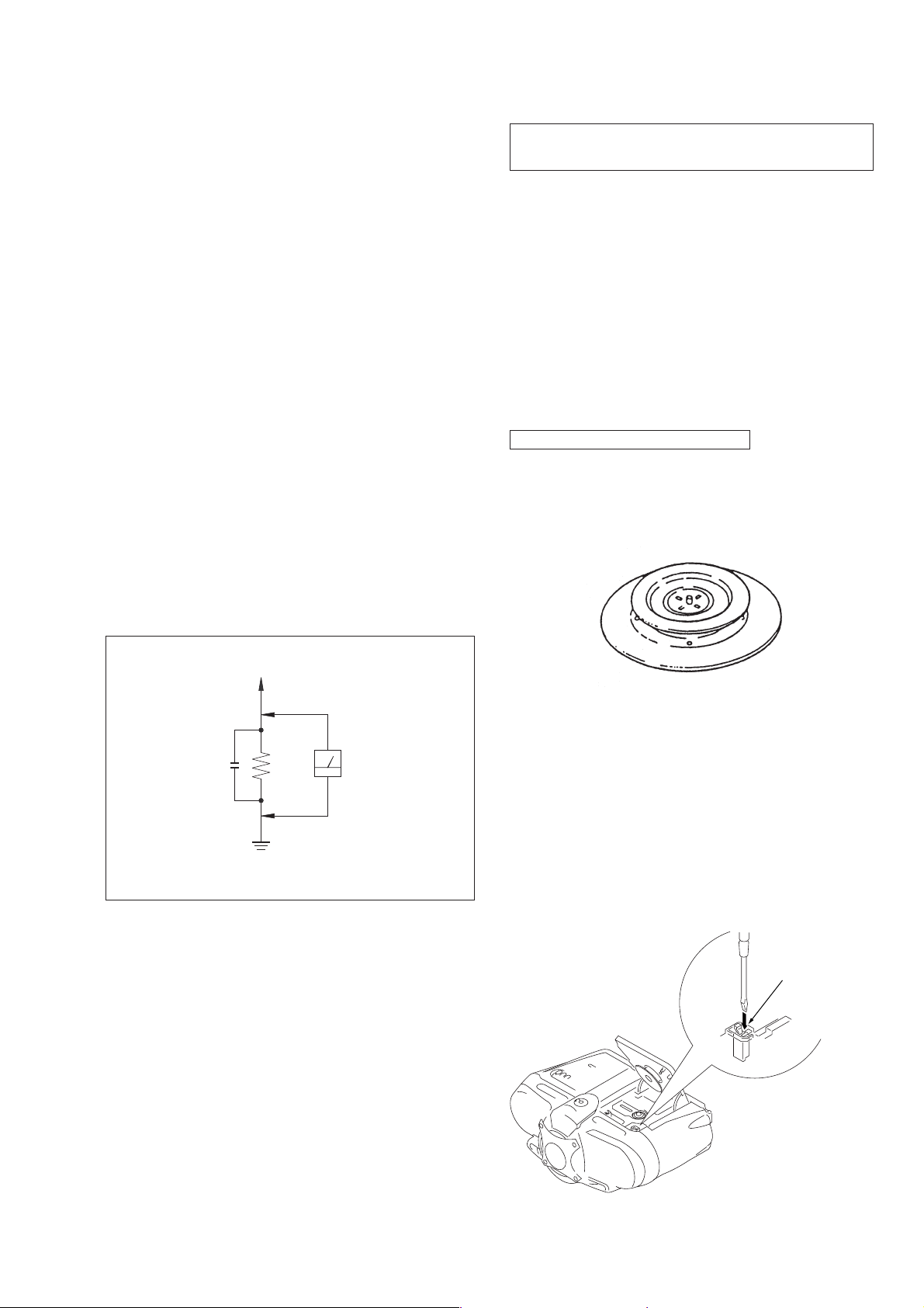
CHUCK PLATE JIG ON REPAIRING
On repairing CD section, playing a disc without the CD lid, use
Chuck Plate Jig.
• Code number of Chuck Plate Jig : X-4918-255-1
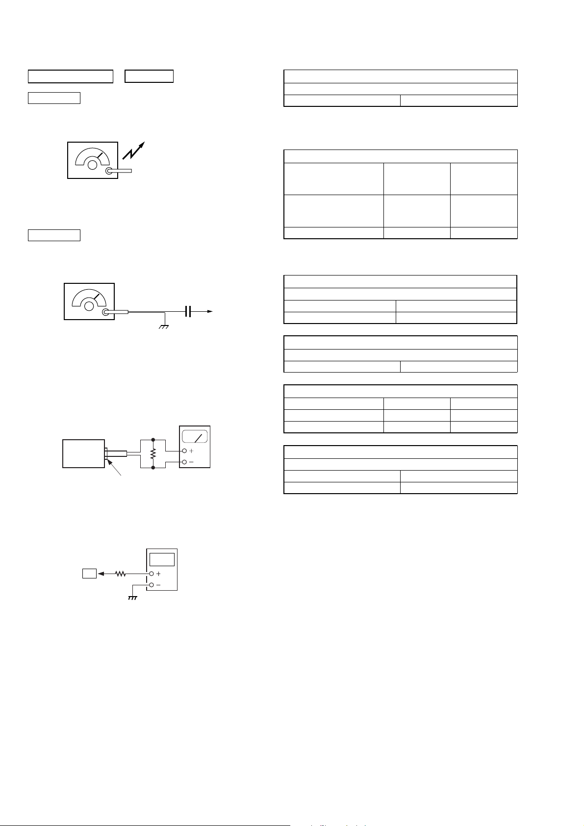
To Exposed Metal
Parts on Set
AC
0.15 µF
Fig. A. Using an A C v oltmeter to check A C leakage.
1.5 kΩ
Earth Ground
Voltmeter
(0.75 V)
LASER DIODE AND FOCUS SEARCH OPERATION
CHECK
1. Press CD open knob.
2. Open the lid for CD.
3. Push on SWITCH (S801) as following figure.
4. Confirm the laser diode emission while observing the objecting
lens. When there is no emission, Auto Power Control circuit or
Optical Pick-up is broken.
Objective lens moves up and down once for the focus search.
Insert a precision
screw driver and push
SWITCH (S801)
3
CFD-G55
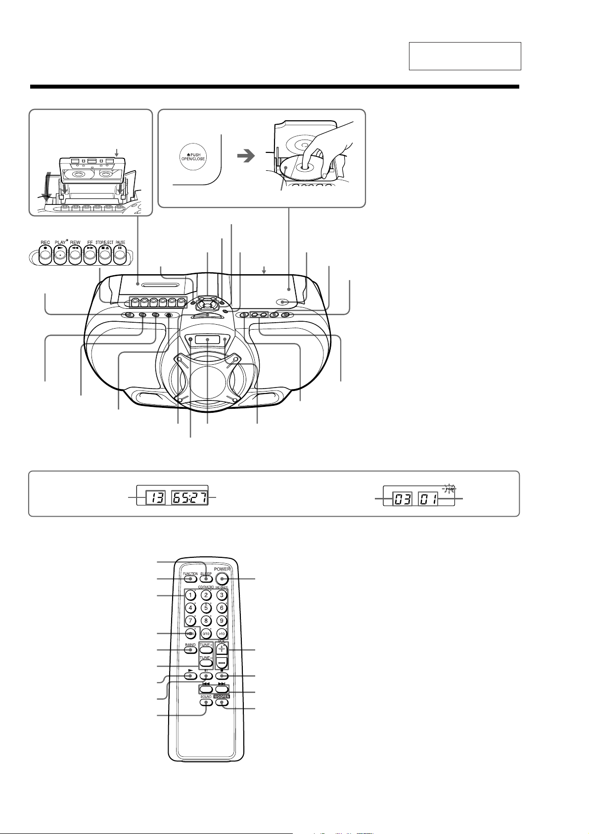
Location of controls
SECTION 2
GENERAL
This section is extracted
from instruction manual.
Inserting a cassette
With the side you want to
play facing upward
POWER
SLEEP
LINE
i
Loading a CD
SOUND
POWER DRIVE
WOOFER
MODE
TUNE –, +
Display
Remote sensor
VOLUME –, +*
DISPLAY
ENTER
MEMORY
LINE IN
(rear)
OPR/BATT
With the labeled side up
Z PUSH
OPEN/CLOSE
u*
*
x
., >
PRESET –, +
BAND
AUTO PRESET
Display
DE
Total track number
Total playing time
Programmed track
Playing order
Remote Control
SLEEP
FUNCTION
Number buttons
MODE
BAND
TUNE+, –
N
X
SOUND
POWER
VOL +*, –
x
.,>
WOOFER
About CD-Rs/CD-RWs
This player can play CD-Rs/CD-RWs
recorded in the CD-DA format*, but
playback capability may vary depending on
the quality of the disc and the condition of
the recording device.
* CD-DA is the abbreviation for Compact
Disc Digital Audio. It is a recording
standard used for Audio CDs.
*The button has a tactile dot.
4
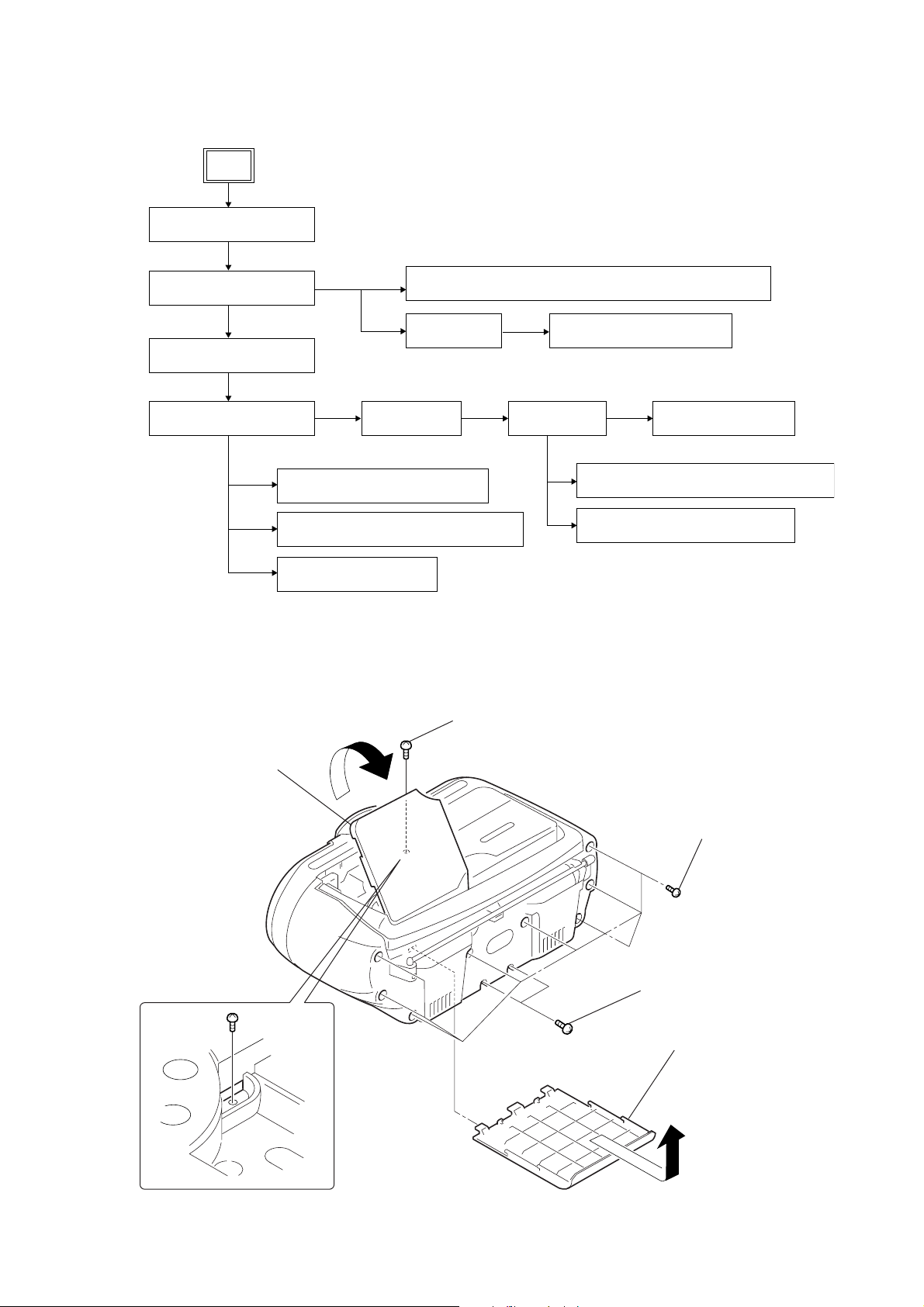
SECTION 3
DISASSEMBLY
• The equipment can be removed using the following procedure.
Set
CFD-G55
Ver 1.1 2002.05
CABINET (FRONT) ASSY-1
CABINET (FRONT) ASSY-2
(page 5)
(page 6)
PANEL (UPPER) ASSY-1
(page 8)
PANEL (UPPER) ASSY-2
(page 8)
POWER, TRANS, V OL SEL BOARD
TUNER BOARD, DUCT (UPPER, LOWER)
BATT COM, BATT BOARD
CONTROL (POWER), CONTROL (CD), HEADPHONE BOARD
PANEL ASSY
(page 7)
MAIN BOARD-1
(page 10)
(page 9)
(page 9)
(page 10)
Note : Follow the disassembly procedure in the numerical order given.
3-1. Cabinet (Front) Assy- 1
(page 6)
LCD BOARD, PANEL (UPPER)
(page 7)
MAIN BOARD-2
(page 11)
MECHANISM DECK SECTION (MF-V5-117)
CD BLOCK SECTION (KSM-213RDP)
PDW, L-R/REG BOARD
(page 12)
(page 11)
(page 12)
4
Open the CD lid in the
direction of the arrow.
detail view
5
screw
+BVTP 3 × 10
3
eight screws
+BVTP 3 × 14
2
two screws
+BVTP 3 × 20
1
Remove the battery case lid
in the direction of the arrow.
5
CFD-G55
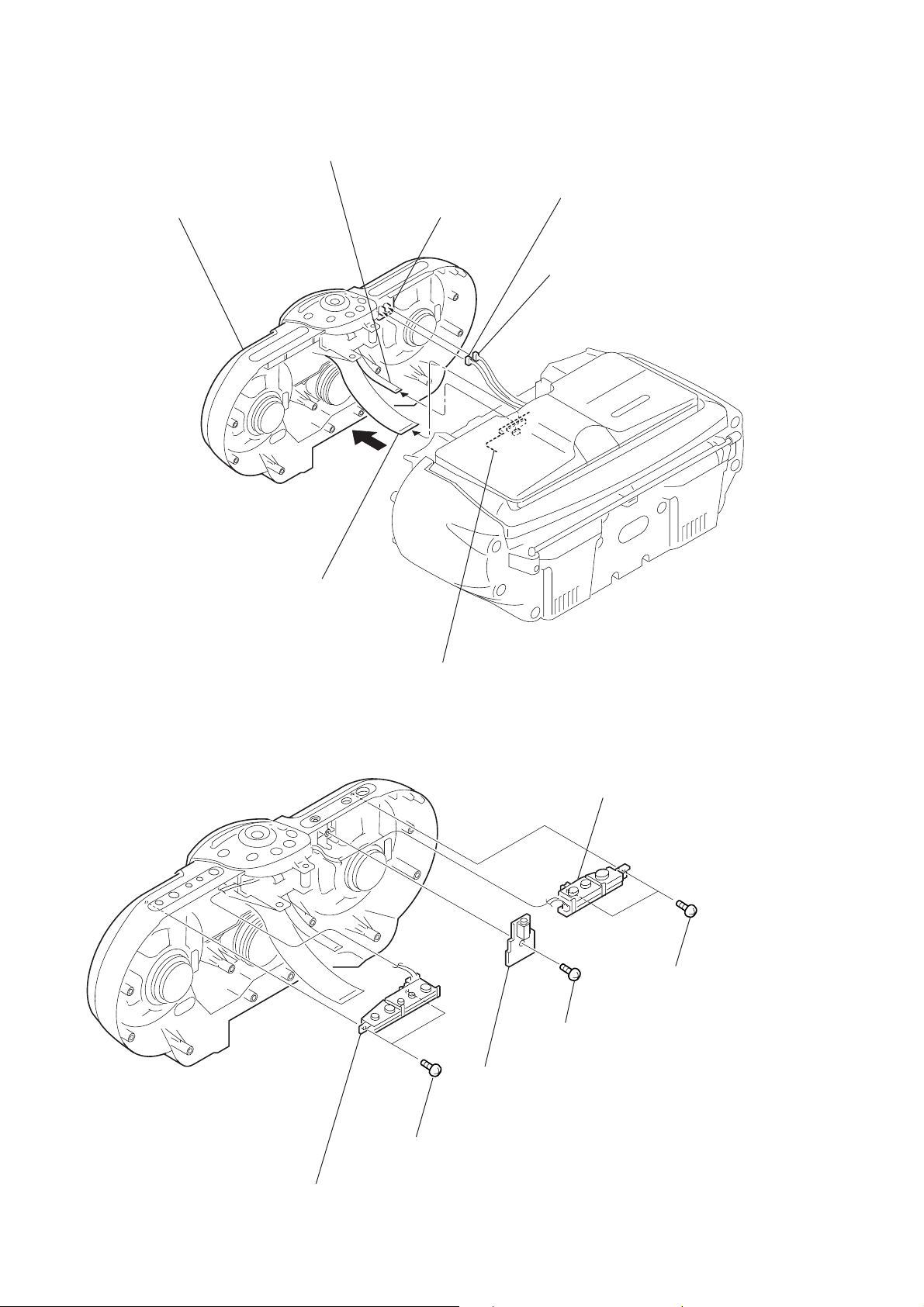
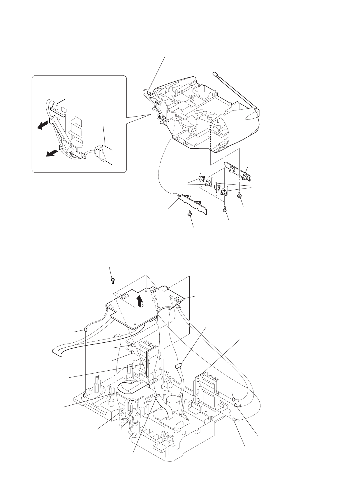
3-2. Cabinet (Front) Assy- 2
1
Remove the cabinet (front) assy
in the direction of the arrow.
2
flexible flat cable
(from MAIN board CNP804)
HEADPHONE board
4
CNP391
(from PWD board KH353)
5
CNP393
(from L-R/REG board KH374)
3
flexible flat cable
(from MAIN board CNP801)
MAIN board
3-3. CONTROL (POWER) , CONTROL (CD) , HEADPHONE Board
2
CONTROL (POWER) board,
power button
3
screw
+BVTP 3
×
10
1
two screws
+BVTP 2.6
×
10
4
HEADPHONE board
5
+BVTP 2.6
6
CONTROL (CD) board,
CD button
two screws
×
10
6
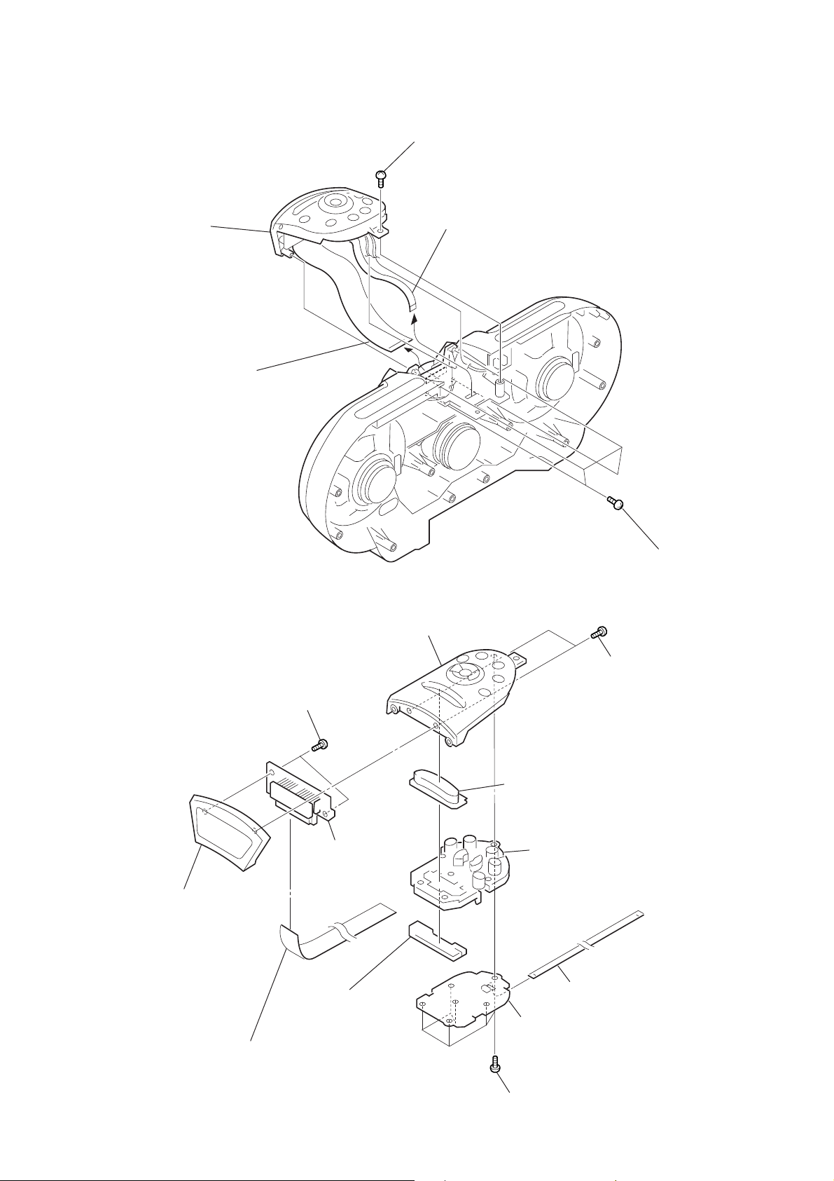
3-4. Panel Assy
0
)
5
panel assy
4
flexible flat cable
(from MAIN board CNP801)
1
screw
+BVTP 3 × 10
3
flexible flat cable
(from MAIN board CNP804)
CFD-G55
3-5. LCD Board, Panel (Upper)
8
+BVTP 2.6 × 10
9
front panel section
two screws
!¡
LCD board
!™
upper Panel
5
PDW button
4
VOL button
2
four screws
+BVTP 2.6 × 1
7
two screws
+BVTP 2.6 × 10
6
light guide plate
(PWD)
0
flexible flat cable
(from MAIN board CNP801)
3
flexible flat cable
(from MAIN board CNP804
2
VOL CONTROL board
1
six screws
+BVTP 2.6 ×10
7
CFD-G55
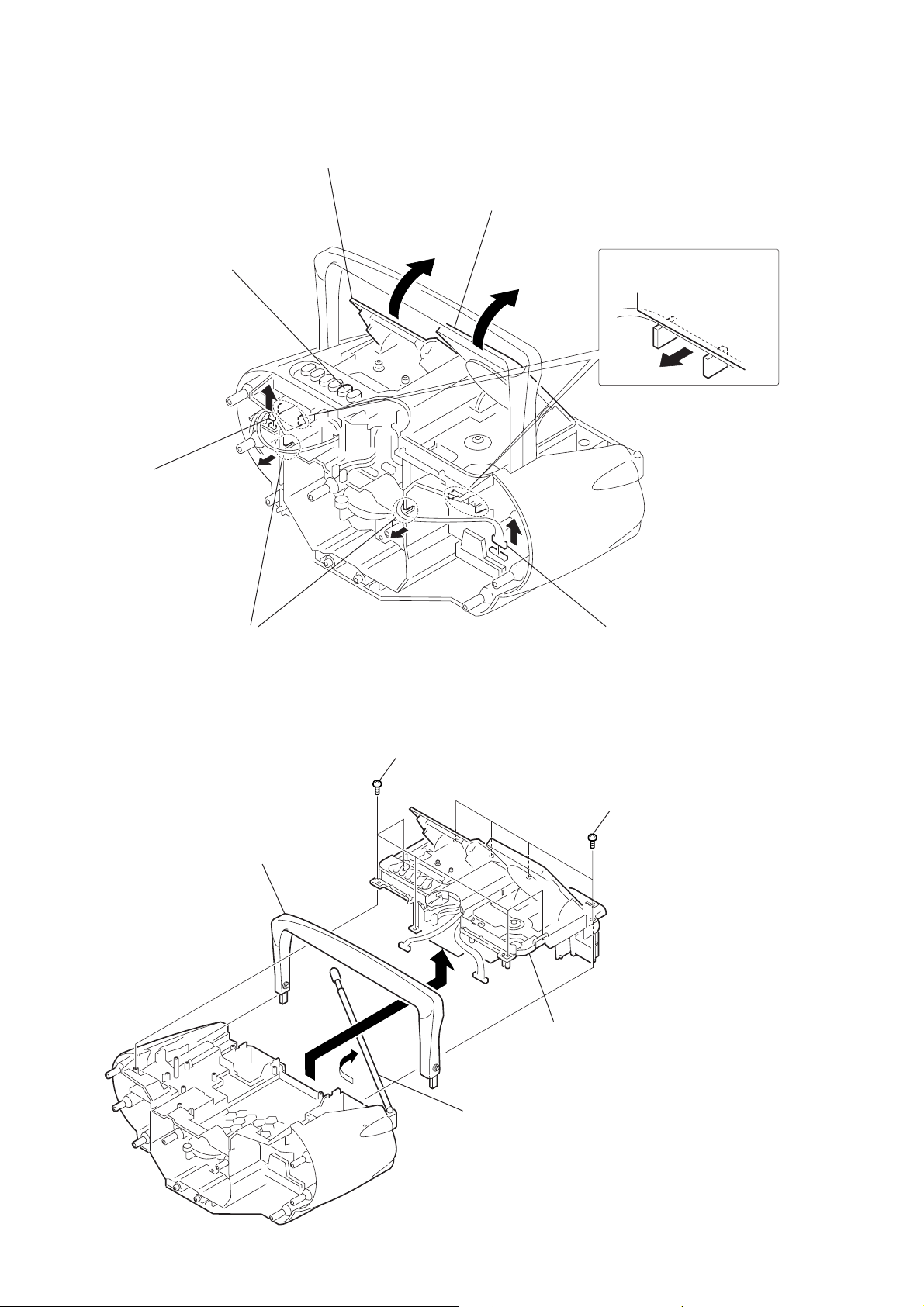
3-6. Panel (Upper) Assy- 1
6
Push STOP/EJECT button.
2
CNP903
(from MAIN board KH301)
7
Open the cassette holder assy
in the direction of the arrow.
5
Open the CD lid in the
direction of the arrow.
4
in the direction of the arrow.
Remove two harnesses
3-7. Panel (Upper) Assy- 2
3
Remove two harnesses
in the direction of the arrow.
2
+BVTP 3
5
handle
five screws
1
CNP1
(from MAIN board KH801)
×
10
1
four screws
+BVTP 3
4
Remove the panel (upper) assy
in the direction of the arrow.
×
10
3
Move the telescopic antenna in
the direction of the arrow.
8
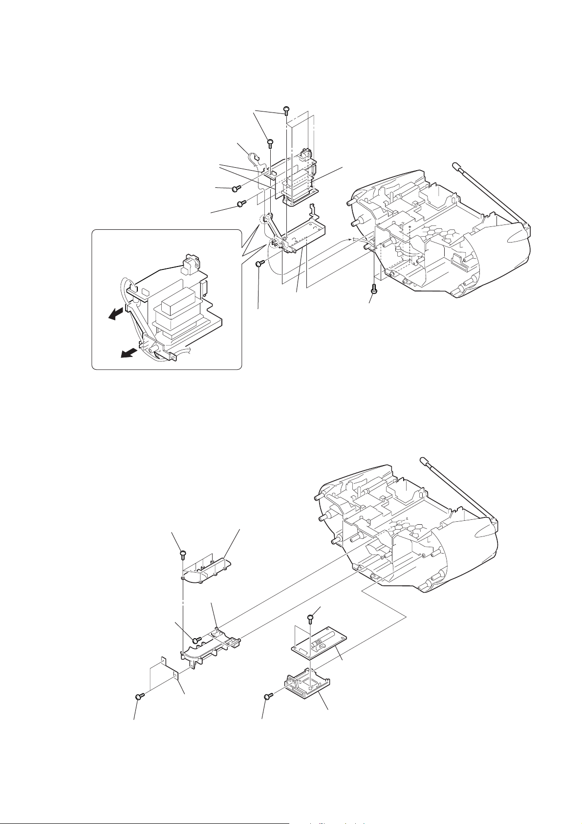
3-8. POWER, TRANS, VOL SEL Board
7
five screws
+BVTP 3 × 10
1
CNP902
(from BATT board KH951)
CFD-G55
Ver 1.1 2002.05
9
POWER board, TRANS board,
VOL SEL board
4
two screws
+BVTP 3 × 10
5
two screws
+BVTP 3 × 10
2
Remove harnesses in the direction
of the arrow.
3-9. TUNER Board, Duct (Upper, Lower)
8
trans chassis
3
screw
+BVTP 3 × 10
power transformer
(T901)
6
four screws
+BVTP 3 × 10
8
seven screws
+BVTP 2.6
7
two screws
+BVTP 3 × 10
5
two screws
+BVTP 3 × 10
0
×
8
9
lower duct
6
woofer bracket
upper duct
1
screw
+BVTP 3 × 10
2
two screws
+BVTP 3 × 10
4
TUNER board
3
chassis (TU)
9
CFD-G55
H
l
2
3-10. BATT COM, BATT Board
2
Remove harnesses in the direction
of the arrow.
BATT board
1
CNP902
(from BATT board KH951)
9
battery
terminal
6
BATT COM board
8
battery termina
3-11. MAIN Board- 1
3
CD door sw
(S801)
PDW board
5
CNP352
4
CNP351
9
four screws
+BVTP 3
5
4
BATT board
7
3
screw
3 × 8 (DIA, 10),+WH
×
10
qs
MAIN board
qs
0
+BVTP 3 × 10
CNP302
screw
3 × 8 (DIA, 10),+W
four screws
L-R/REG board
10
2
flexible flat cable
CNP802
!¡
hook
1
flexible flat cable
CNP805
8
CNP371
6
7
CNP37
CNP373
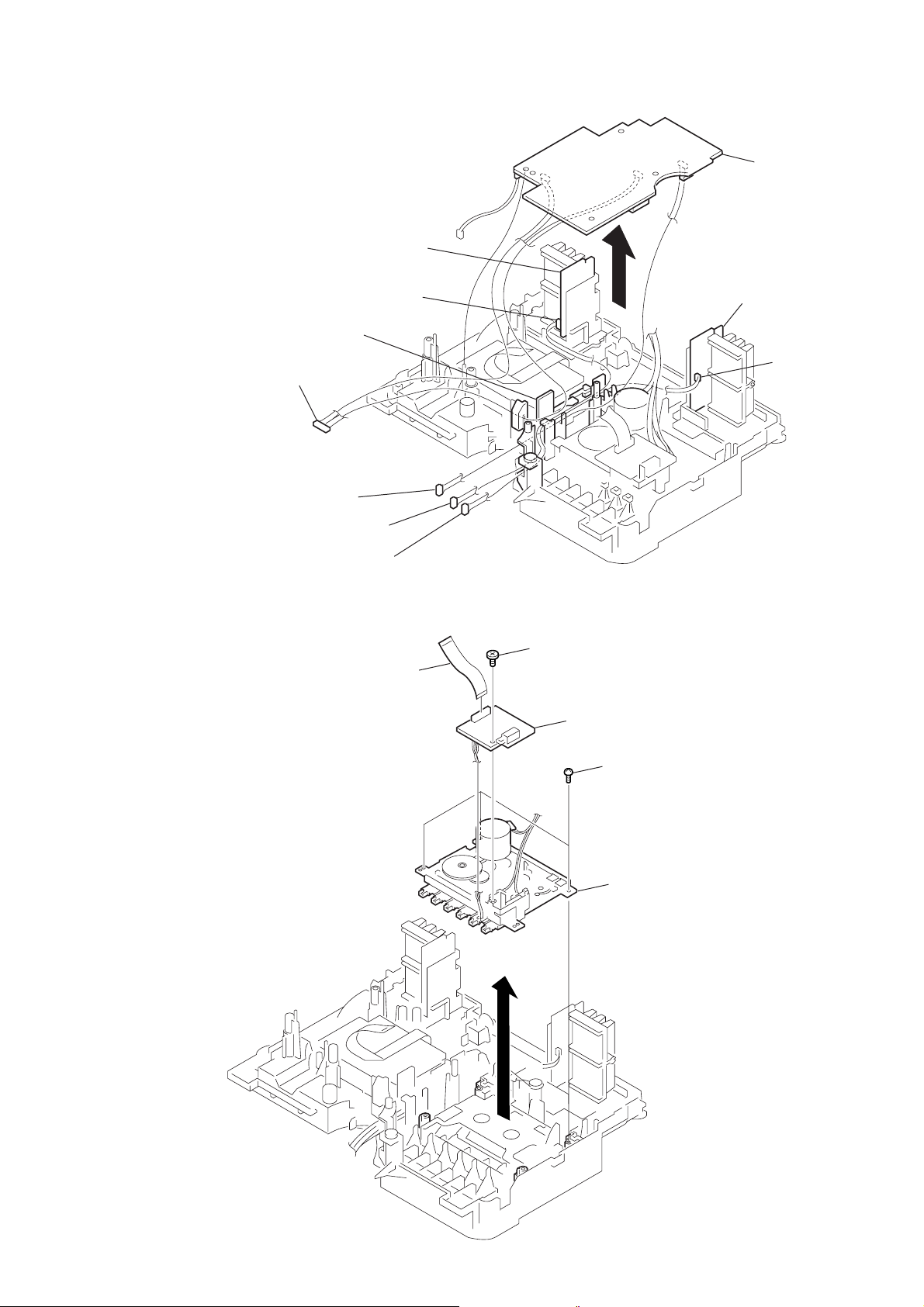
3-12. MAIN Board- 2
d
PDW board
CFD-G55
5
MAIN boar
CNP353
chassis (CD)
1
from TUNER board CNP1
4
from POWER board CNP903
2
from HEADPHONE board CNP391
3
from HEADPHONE board CNP393
3-13. Mechanism Deck Section (MF-V5-117)
1
flexible flat cable
(from MAIN board CNP805)
2
screw
+PTT 2
3
TC board
L-R/REG board
CNP374
×
6
4
three screws
+BVTP 3
5
mechanism deck section
(MF-V5-117)
×
10
11
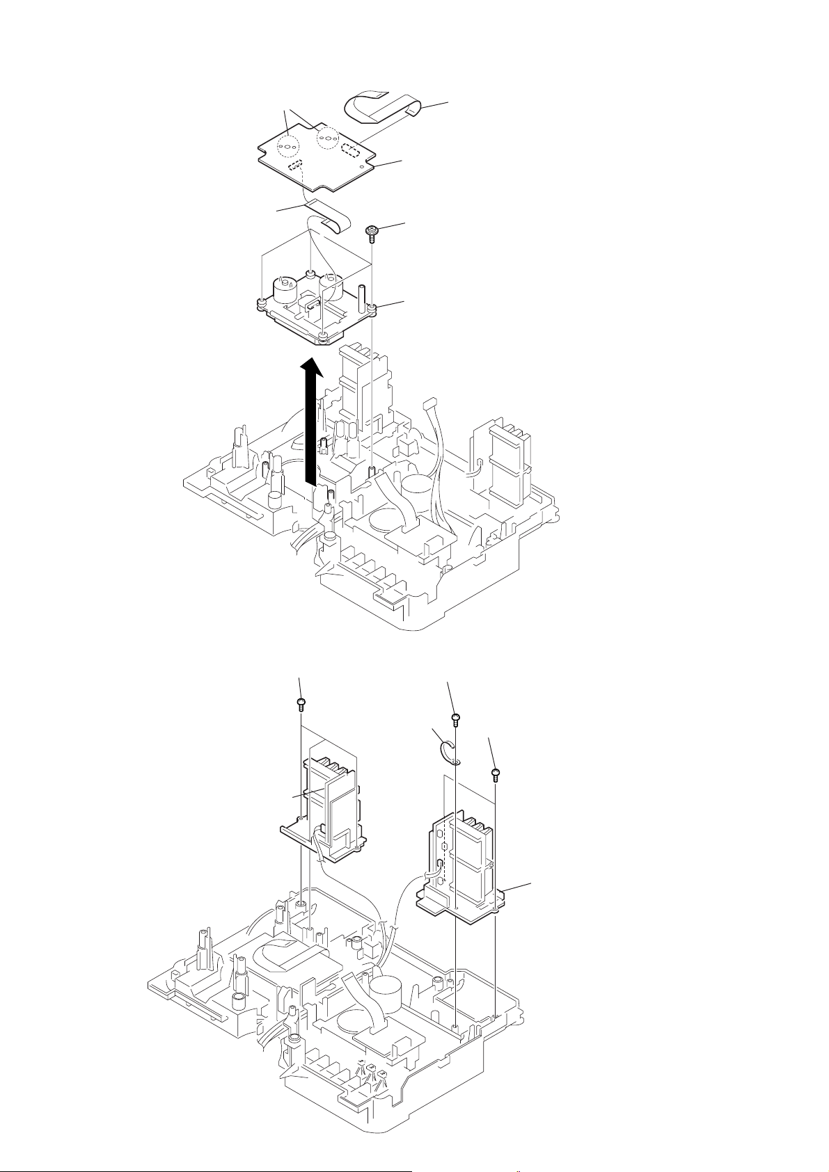
CFD-G55
)
3-14. CD Block Section
(KSM-213RDP)
3
CNP701
2
Remove solderings
from the four points.
flexible flat cable
1
flexible flat cable
(from MAIN board CNP802
4
CD board
5
four screws
+PWH 2.6
6
CD block section
(KSM-213RDP)
×
10
3-15. PDW, L-R/REG Board
6
PDW board,
Chassis (HS, R)
5
three screws
+BVTP 3 × 10
2
1
+BVTP 3 × 10
clamp
screw
3
two screws
+BVTP 3
4
chassis (HS, L)
×
10
L-R/REG board,
12
SECTION 4
y
ADJUSTMENTS
CFD-G55
4-1. Mechanical Adjustments
PRECAUTION
1. Clean the following parts with a denatured-alcohol-moistened
swab :
record/playback head pinch roller
erase head rubber belts
capstan
2. Demagnetize the record/playback head with a head demagnetizer. (Do not bring the head demagnetizer close to the erase
head.)
3. Do not use a magnetized screwdriver for the adjustments.
4. The adjustments should be performed with the rated power
supply voltage (12V) unless otherwise noted.
Torque Measurement
Torque Torque Meter Meter Reading
1.77 – 5.88 mN•m
Forward CQ-102C (18 – 60 g•cm)
(0.25 – 0.83 oz•inch)
Forward
Back Tension
Fast Forward CQ-201B (45 – 95 g•cm)
Rewind CQ-201B (45 – 95 g•cm)
CQ-102C (1.0 – 5.0 g•cm)
0.1 – 0.49 mN•m
(0.014 – 0.069 oz•inch)
4.42 – 9.31 mN•m
(0.62 – 1.32 oz•inch)
4.42 – 9.31 mN•m
(0.62 – 1.32 oz•inch)
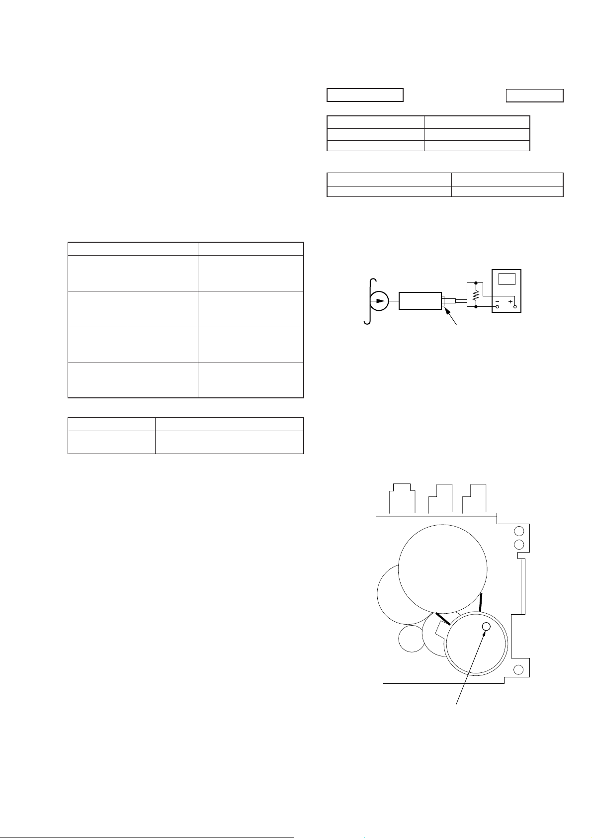
4-2. Electrical Adjustments
TAPE SECTION
Standard Output Level
Output terminal HP OUT
load impedance 32 Ω
output signal level 0.25V (–10dB)
Test T ape
Type Signal Used for
WS-48A 3kHz, 0dB Tape Speed Adjustment
Tape Speed Adjustment
Procedure :
Mode : Playback
test tape
WS-48A
(3kHz, 0dB)
set
Adjustment so than the value on the digital frequency counter is
3,000 Hz.
Adjustment V alue : 3,000Hz
Standard V alue : 2,940 - 3,060Hz
J391
32
(
0dB = 0.775V
digital frequenc
counter
Ω
i
)
Tape Tension Measurement
Torque Meter Meter Reading
CQ-403A
more than 60g
(more than 2.12 oz)
Frequency difference between the beginning and the end of the tape
should be within 1.5% (45Hz).
Adjustment Location : Mechanism deck
Tape speed adjustment
control inside motor
13
CFD-G55
c
)
Ver 1.1 2002.05
TUNER SECTION
AM Section
Function switch : AM
AM RF signal
generator
30% amplitude modulation by 400Hz
signal.
Output level : as low as possible
FM Section
Function switch : FM
FM RF signal
generator
33.75kHz frequency deviation by
1kHz signal.
Output level : as low as possible
0dB = 1 µV
Put the lead-wire
antenna close to
the set.
0.01
AM IF ADJUSTMENT
Adjust for a maximum reading on level meter.
T1 450 kHz
( ): 9 kHz step (MY, SP, EA)
< >: 10 kHz step (MY, SP, EA)
no mark: Others
AM FREQUENCY COVERAGE ADJUSTMENT
Frequency Display
Reading on Digital voltmeter 1.0 ± 0.1 V
Adjustment Part L 4 confirmation
530 kHz 1,710 kHz
(531 kHz) (1,611 kHz)
<530 kHz> <1,610 kHz>
5.3 ± 0.8V
(4.8 ± 0.8V)
<4.8± 0.8V>
< >: 9 kHz step (MY, SP, EA)
no mark: Others
AM TRACKING ADJUSTMENT
µ
F
telescopi
antenna
terminal
Adjust for a maximum reading on level meter.
L3 CT3
620 kHz <621kHz> 1,400 kHz <1,404 kHz>
FM IF ADJUSTMENT
Adjust for a maximum reading on level meter.
T2 10.7 MHz
• Connecting Level Meter (FM and AM)
level meter
(range: 0.5–5 V ac
Ω
32
set
J391 ( i
)
• Connecting Digital Voltmeter (FM and AM)
digital
voltmeter
Ω
100 k
TP CV
•Repeat the procedures in each adjustment several times, and the
frequency coverage and tracking adjustments should be finally
done by the trimmer capacitors.
FM FREQUENCY COVERAGE ADJUSTMENT
Frequency Display 87.5 MHz 108 MHz
Reading on Digital voltmeter
1.3 ± 0.4 V 3.0 ± 0.3 V
Adjustment Part confirmation L2
FM TRACKING ADJUSTMENT
Adjust for a maximum reading on level meter.
L1 CT1
87.5 MHz 108 MHz
Abbreviation
MY : Malaysia model.
SP : Singapore model.
EA : Saudi Arabia model.
Adjustment Location : TUNER board (See page 16)
14
CFD-G55
RF level
0.85
±
0.2 Vp-p (LPC ON)
0.95
±
0.4 Vp-p (LPC OFF)
VOLT/DIV : 200mV
TIME/DIV : 500 ns
B
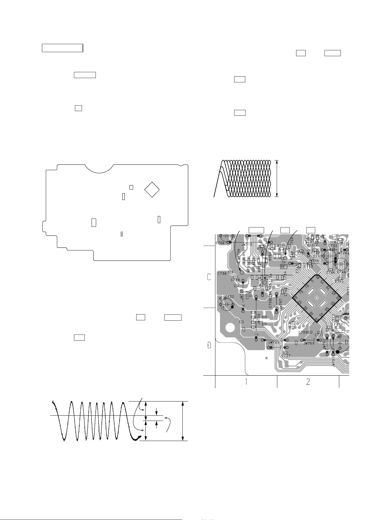
CD SECTION
CD Test Mode
• How to put the set into CD test mode
1. Press the POWER button to turn the power on.
2. Insert the test disc (YEDS-18). (Part No. : 3-702-101-01)
(Function is set to CD.)
3. Set the CD test mode by momentary shorting both sides of
TEST- 1 on MAIN board.
4. Press the x button two times. The set is set to the CD test
mode.
(The message 80 is displayed.)
• How to release the CD test mode
Turn the power off.
[MAIN BOARD] (Conductor side)
IC803
IC802
IC321
IC801
IC805
Focus Bias Check
1. Connect an oscilloscope between TP RF and TP VREF on
CD board.
2. Insert the test disc (YEDS-18).
3. Set the CD test mode.
4. Press the u button three times (LPC ON).
5. Confirm that the oscilloscope waveform is as shown in the figure
below. (eye pattern)
A good eye pattern means that the diamond shape (◊) in the
center of the waveform can be clearly distinguished.
6. Press the u button.(LPC OFF)
7. Perform confirmation in step 4 again.
• RF Signal Reference Waveform (eye pattern)
[CD BOARD] (Conductor side)
TEST-1
Traverse Waveform Check
1. Connect an oscilloscope between TP TE and TP VREF on
CD board.
2. Set the CD test mode.
3. Press the u botton to play the test disc (YEDS-18).
4. Confirm that the center of the traverse waveform will be at 0V.
5. Confirm that the peak-to-peak voltage value of the traverse
waveform meets the specification.
6. Release the CD test mode.
• Traverse waveform
VOLT/DIV : 200mV
TIME/DIV : 1 ms
symmetry
TP VREF TP TE TP RF
IC701
0V
A = 0
B = 0.95
±
220 mV
±
0.55 Vp-p
A (DC voltage)
15
CFD-G55
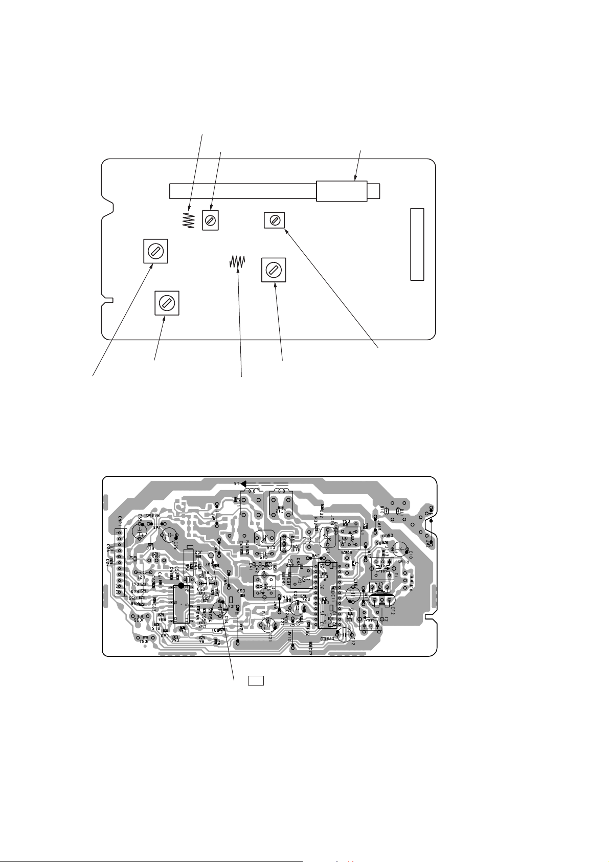
t
Adjustment Location :
[TUNER BOARD] (Component side)
L1: FM Tracking Adjustment
T2: FM IF Adjustment
T1: AM IF Adjustment
CT1: FM Tracking Adjustment
L4: AM Frequency Coverage Adjustment
L2: FM Frequency Coverage Adjustment
L3: AM Tracking Adjustment
CNP1
CT3: AM Tracking Adjustmen
(Conductor side)
IC2
IC1
TP CV
AM/FM Frequency Coverage Adjustment
16
SECTION 5
d
DIAGRAMS
CFD-G55
Ver 1.1 2002.05
5-1. Circuit Boards Location
CONTROL (POWER) board
HEADPHONE board
POWER board
LCD board
VOL SEL board
BATT board
TC board
CONTROL (VOL) board
CONTROL (CD) board
L-R/REG board
BATT COM board
MAIN board
TUNER board
Note on Printed Wiring Boards:
• X : parts extracted from the component side.
f
•
• : Pattern from the side which enables seeing.
(The other layers' patterns are not indicated.)
: internal component.
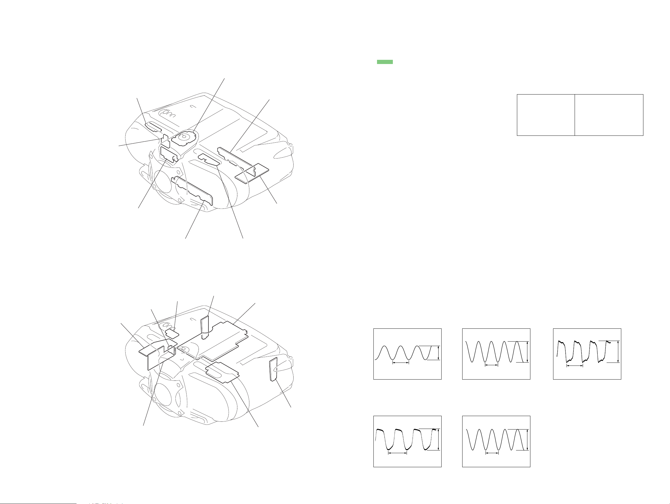
• WA VEFORMS
– TUNER Section –
– TC Section –
Note on Schematic Diagram:
• All capacitors are in µF unless otherwise noted. p: pF.
50 WV or less are not indicated except for electrolytics
and tantalums.
• All resistors are in Ω and 1/
specified.
f
•
• 2 : nonflammable resistor.
• C : panel designation.
• A : B+ Line.
• H : adjustment for repair.
•Total current is measured with no cassette installed.
•Power voltage is dc 12 V and fed with regulated dc power
•Voltages and waveforms are dc with respect to ground
•Voltages are taken with a VOM (Input impedance 10 MΩ).
•Waveforms are taken with a oscilloscope.
• Circled numbers refer to waveforms.
• Signal path.
•Abbreviation
: internal component.
Note:
The components identified by mark 0 or dotted
line with mark 0 are criti-
cal for safety.
Replace only with part
number specified.
supply from battery terminal.
under no-signal (detuned) conditions.
Voltage variations may be noted due to normal produc-
tion tolerances.
Voltage variations may be noted due to normal produc-
tion tolerances.
F : FM
f : AM
E : PB
a : REC
J : CD
d : LINE IN
CND : Canadian model.
EA : Saudi Arabia model.
MY : Malaysia model.
SP : Singapore model.
E92 : Chilean and Peruvian model.
MX : Mexican model.
4
W or less unless otherwise
Note:
Les composants identifiés par
une marque 0 sont critiques
pour la sécurité.
Ne les remplacer que par une
piéce portant le numéro
spécifié.
– CD Section –
TRANS board
1
IC2 w; (XOUT)
µ
s
13.3
500 mV/DIV, 4 µs/DIV
1.4 Vp-p
2
Q301 collector
(TAPE REC)
µ
s
18
1 V/DIV, 10 µs/DIV
3.1 Vp-p
3
IC701 rk (XOUT)
59 ns
4.2 Vp-p
1 V/DIV, 20 ns/DIV
– MAIN Section –
PDW boar
4
IC801 ua (XT2)
CD board
µ
s
30.5
1 V/DIV, 10 µs/DIV
3.6 Vp-p
5
IC801 ug (X2)
238 ns
1 V/DIV, 100 ns/DIV
3.7 Vp-p
1717
 Loading...