

SONY CF150 TS Service Manual
ICF-C630
SERVICE MANUAL
Ver 1.0 2003. 06
SPECIFICATIONS
Time display:
12-hour system
Frequency range:
FM: 87.5 - 108 MHz
AM: 530 - 1710 kHz
Speaker:
Approx. 5.7 cm dia., 4 ohm
Power output:
120 mW (at 10% harmonic distortion)
Power requirements:
3 V DC, two R6 (size AA) batteries
External power source:
DC IN 4.5 V
Dimensions:
Approx. 94 × 104 × 82 mm (w/h/d)
incl. projecting parts and controls
Mass:
Approx. 313 g incl. batteries
Accessories supplied:
AC power adaptor (1)
Design and specifications are subject to change without notice.
Australian Model
9-877-483-01
2003F04-1
© 2003. 06
FM/AM CLOCK RADIO
Sony Corporation
Personal Audio Company
Published by Sony Engineering Corporation
1

ICF-C630
Notes on Chip Component Replacement
• Never reuse a disconnected chip component.
• Notice that the minus side of a tantalum capacitor may be dam-
aged by heat.
TABLE OF CONTENTS
1. SERVICING NOTES
1-1. Dial Pointer Setting ............................................................. 3
1-2. Installing the Tuner Board................................................... 3
2. GENERAL
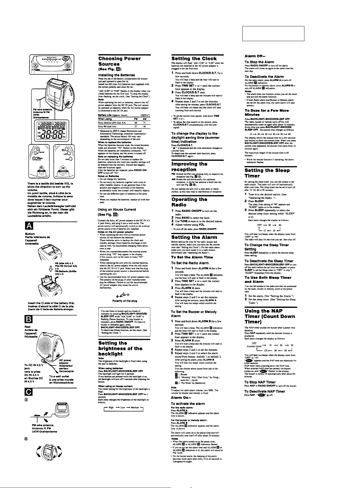
Choosing Power Sources .........................................................4
Setting the brightness of the backlight ....................................4
Setting the Clock .....................................................................4
Improving the reception .......................................................... 4
Operating the Radio................................................................. 4
Setting the Alarm..................................................................... 4
Setting the Sleep Timer ........................................................... 4
Using the NAP Timer (Count Down Timer) ........................... 4
3. DISASSEMBLY
3-1. Cover Assy .......................................................................... 5
3-2. Tuner Board......................................................................... 6
3-3. Cabinet (Upper) Assy.......................................................... 6
3-4. Microcomputer Board, Key (Left) Board,
Key (Right) Board ............................................................... 7
4. ELECTRICAL ADJUSTMENTS................................... 8
5. DIAGRAMS
5-1. IC Block Diagram ............................................................. 10
5-2. Block Diagram .................................................................. 11
5-3. Printed Wiring Board –Tuner Section– ............................. 12
5-4. Printed Wiring Boards –Micon Section– .......................... 13
5-5. Schematic Diagram ........................................................... 14
5-6. IC Pin Description.............................................................15
SAFETY-RELATED COMPONENT W ARNING!!
6. EXPLODED VIEWS
6-1. Cabinet (Lower) Section ................................................... 16
6-2. Cover Assy Section ........................................................... 17
7. ELECTRICAL PARTS LIST ........................................ 18
COMPONENTS IDENTIFIED BY MARK 0 OR DOTTED LINE
WITH MARK 0 ON THE SCHEMATIC DIAGRAMS AND IN
THE PARTS LIST ARE CRITICAL TO SAFE OPERATION.
REPLACE THESE COMPONENTS WITH SONY P ARTS WHOSE
PART NUMBERS APPEAR AS SHOWN IN THIS MANUAL OR
IN SUPPLEMENTS PUBLISHED BY SONY.
2

1-1. DIAL POINTER SETTING
1
pointer
SECTION 1
SERVICING NOTES
knob (VOL)
3
4
knob (TUNE)
ICF-C630
mark
front
2
cabinet (lower)
knob (VOL)
knob (TUNE)
pointer
pointer
1-2. INSTALLING THE TUNER BOARD
6
screw
(+P2.6 x 8)
knob (VOL)
3
5
Adjust RV1 to the protrusion
on the knob (VOL).
RV1
2
Turn the spindle of CV1 fully
in the arrow direction.
4
TUNER board
1
Turn the knob (TUNE) fully
in the arrow direction.
knob (TUNE)
3
ICF-C630
SECTION 2
GENERAL
This section is extracted
from instruction manual.
4
SECTION 3
n
DISASSEMBLY
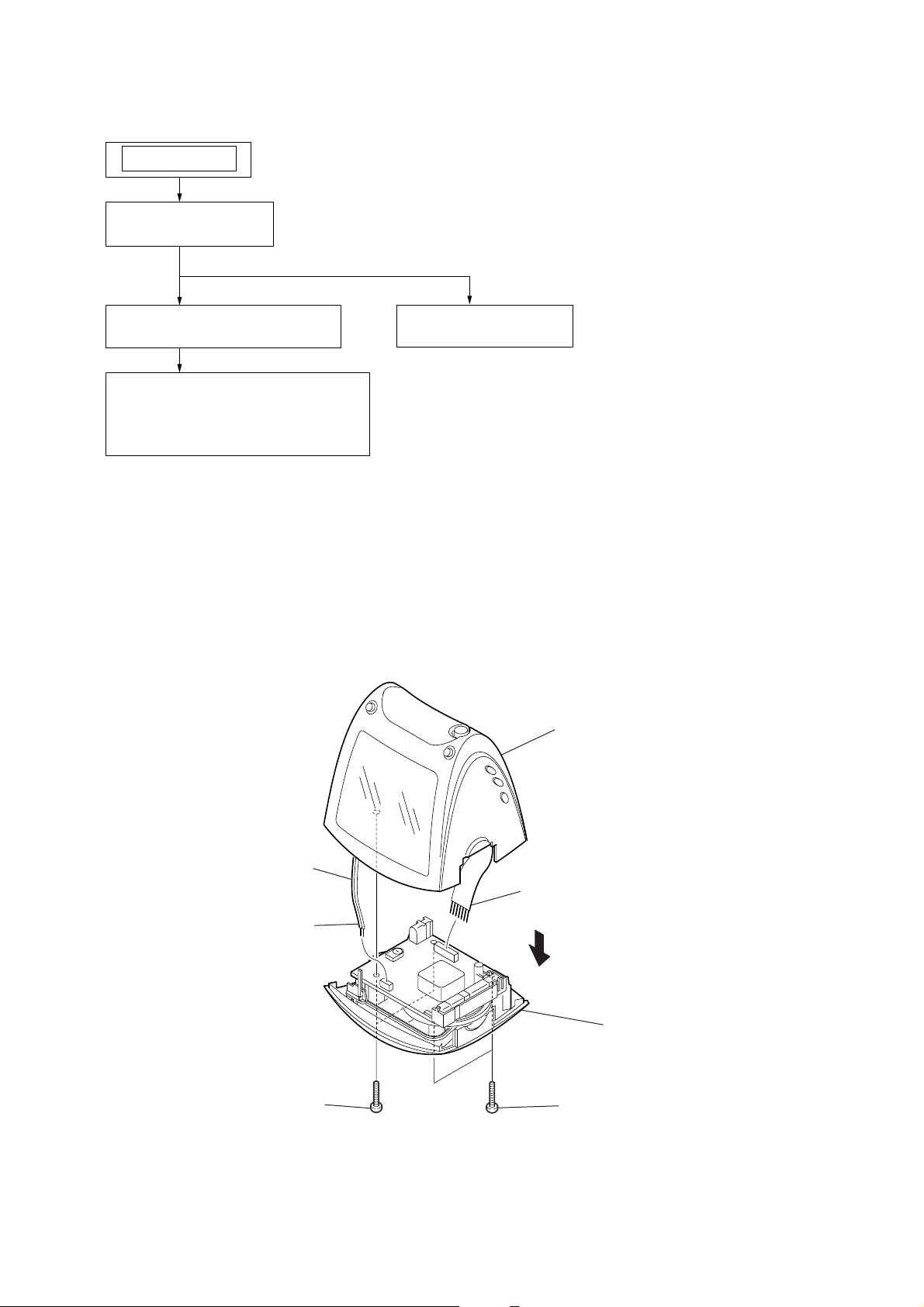
Note : This set can be disassemble according to the following sequence.
SET
3-1. COVER ASSY
(Page 5)
ICF-C630
3-3. CABINET (UPPER) ASSY
(Page 6)
3-2. TUNER BOARD
(Page 6)
3-4. MICROCOMPUTER BOARD,
KEY (LEFT) BOARD,
KEY (RIGHT) BOARD
(Page 7)
Note : Follow the disassembly procedure in the numerical order given.
3-1. COVER ASSY
6
cover assy
red
4
CN2
2
two screws
(+P3 x 20)
5
CN1
3
7
cabinet (lower) sectio
1
two screws
(+P3 x 20)
5

ICF-C630
y
3-2. TUNER BOARD
1
screw
(+P2.6 x 8)
3
Removal the two solders.
black
red
2
TUNER board
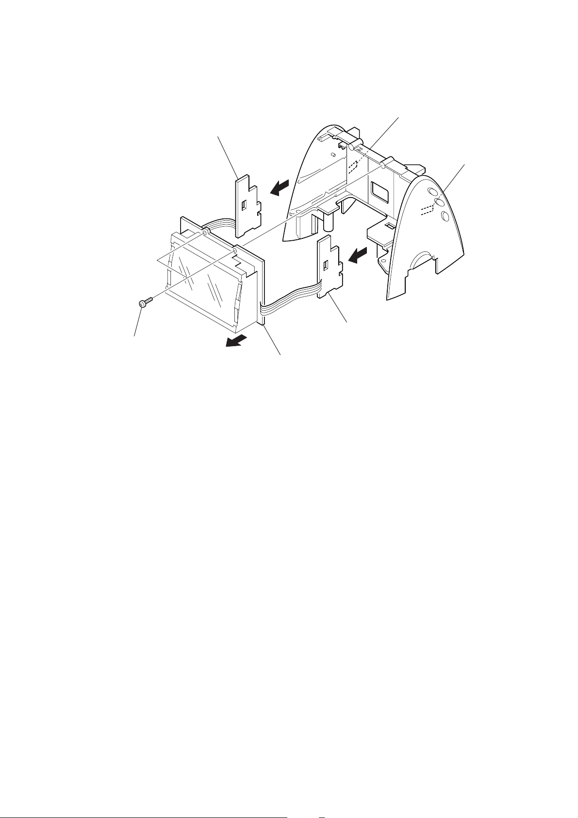
3-3. CABINET (UPPER) ASSY
4
cover sub assy
3
5
cabinet (upper) ass
1
two screws
2
(+P2.6 x 8)
two screws
(+P2.6 x 8)
6
3-4. MICROCOMPUTER BOARD, KEY (LEFT) BOARD, KEY (RIGHT) BOARD
w
4
6
KEY (LEFT) board
5
8
claw
7
ICF-C630
cla
1
two screws
(+P2.6 x 8)
2
9
KEY (RIGHT) board
3
MICROCOMPUTER board
7
 Loading...