

Sony CDXGT-06-HP, CDXGT-06 Service manual
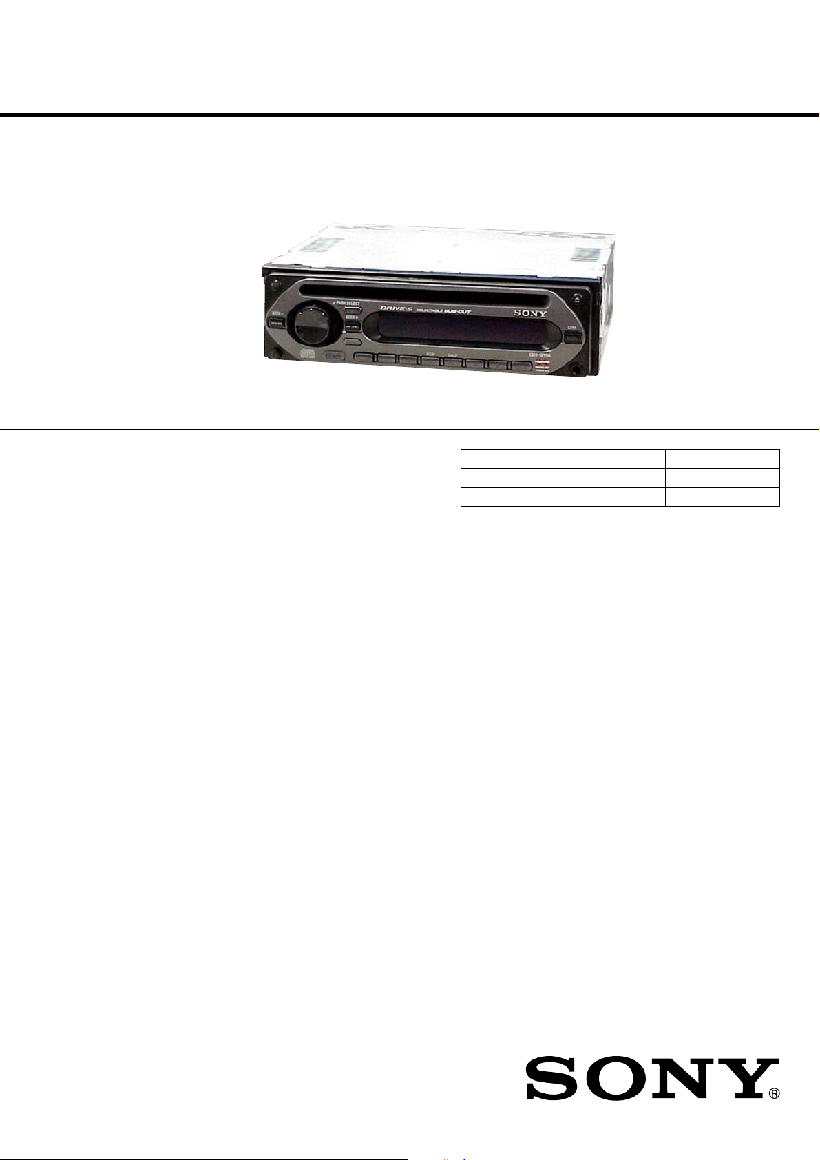
CDX-GT06/CXS-GT06HP
SERVICE MANUAL
Ver. 1.0 2006.07
• CXS-GT06HP is composed of CDX-GT06,
2 way speaker, 3 way speaker.
• The tuner and CD sections have no adjustments.
AUDIO POWER SPECIFICATIONS
POWER OUTPUT AND TOTAL HARMONIC DISTORTION
22 watts per channel minimum continuous average power into
4 ohms, 4 channels driven from 20 Hz to 20 kHz with no more
than 5% total harmonic distortion.
(Photo: CDX-GT06)
US Model
Model Name Using Similar Mechanism CDX-GT10W/GT100
CD Drive Mechanism Type MG-611XE-186//C
Optical Pick-up Name KSS1000E
CD Player section
Signal-to-noise ratio: 120 dB
Frequency response: 10 – 20,000 Hz
Wow and flutter: Below measurable limit
Tuner section
FM
Tuning range: 87.5 – 107.9 MHz
Antenna terminal: External antenna connector
Intermediate frequency: 10.7 MHz/450 kHz
Usable sensitivity: 9 dBf
Selectivity: 75 dB at 400 kHz
Signal-to-noise ratio: 67 dB (stereo), 69 dB (mono)
Harmonic distortion at 1 kHz:
0.5 % (stereo), 0.3 % (mono)
Separation: 35 dB at 1 kHz
Frequency response: 30 – 15,000 Hz
AM
Tuning range: 530 – 1,710 kHz
Antenna terminal: External antenna connector
Intermediate frequency: 10.7 MHz/450 kHz
Sensitivity: 30 µV
SPECIFICATIONS
Power amplifier section
Outputs: Speaker outputs (sure seal connectors)
Speaker impedance: 4 – 8 ohms
Maximum power output: 45 W × 4 (at 4 ohms)
General
Outputs: Audio outputs terminal (sub/rear switchable)
Power antenna relay control terminal
Power amplifier control terminal
Inputs: Antenna input terminal
AUX input jack (stereo mini jack)
Tone controls: Low: ±10 dB at 60 Hz (XPLOD)
Mid: ±10 dB at 1 kHz (XPLOD)
High: ±10 dB at 10 kHz (XPLOD)
Power requirements: 12 V DC car battery (negative ground)
Dimensions: Approx. 178 × 50 × 179 mm
(7 1/8 × 2 × 7 1/8 in) (w/h/d)
Mounting dimensions: Approx. 182 × 53 × 161 mm
(7 1/4 × 2 1/8 × 6 3/8 in) (w/h/d)
Mass: Approx. 1.2 kg (2 lb 11 oz)
Supplied accessories: Parts for installation and connections (1 set)
– Continued on next page –
9-887-357-01
2006G04-1
© 2006.07
FM/AM COMPACT DISC PLAYER
Sony Corporation
eVehicle Division
Published by Sony Techno Create Corporation
CDX-GT06/CXS-GT06HP
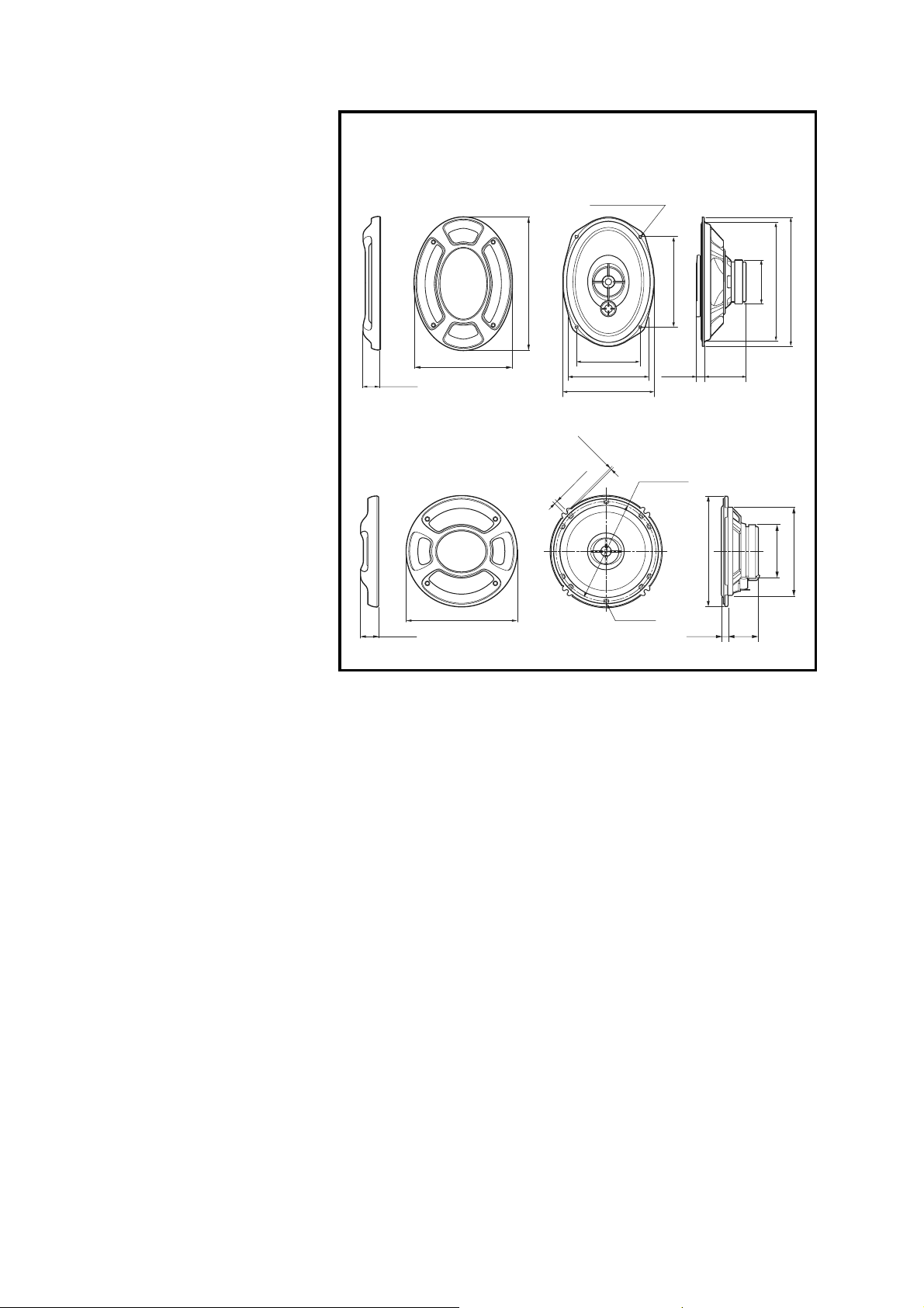
6 × 9 Speaker (3-way Speaker)
Speaker Coaxial 3-way:
Woofer 16 × 24 cm
(6 3/8 × 9 1/2 in), cone type
Midrange 5.5 cm (2 1/4 in),
cone type
Tw eeter 1.4 cm (9/16 in),
balanced dome type
Peak power 300 W
Rated power 60 W
Impedance 4 Ω
Sensitivity 93 dB/W/m
Frequency response 27 – 30,000 Hz
Mass Approx. 1,150 g (2 lb 9 oz)
per speaker
Supplied accessory Parts for installation
6 1/2 Speaker (2-way Speaker)
Speaker Coaxial 2-way:
Woofer 16 cm (6 3/8 in),
HOP, cone type
Tw eeter 4 cm (1 5/8 in),
Al, cone type
Peak power 190 W
Rated power 40 W
Impedance 4 Ω
Sensitivity 90 dB/W/m
Frequency response 35 – 22,000 Hz
Mass Approx. 560 g (1 lb 4 oz) per
speaker
Supplied accessory Parts for installation
Design and specifications are subject to change
without notice.
Dimensions
Dimensiones
6 × 9 Speaker
Altavoz de 6 × 9
35 (1 7/16)
1
6
/2 Speaker
Altavoz de 6
27 (1
1
1
/8)
Unit: mm (in)
Unidad: mm
4.5 × 7.5 (3/16 × 5/16)
)
2
/
1
264 (10
3
/4)
194 (7
/
2
3
/4)
ø 168 (6
117 (4 5/8)
1
/8)
153 (6
5
168 (6
/8)
2.5 (
1
/
8
)
)
2
3
/
7
5 (
ø 5 (7/32)
)
8
/
5
166 (6
16 (21/32) 75 (3)
5
/8)
ø 142 (5
8.9 (
)
4
/
1
ø 158 (6
3
/8)
)
)
)
4
4
8
/
/
/
1
3
3
222 (8
237 (9
ø 80 (3
ø 75 (3)
ø 125 (5)
44
3
(1
/4)
SAFETY-RELATED COMPONENT WARNING!!
COMPONENTS IDENTIFIED BY MARK 0 OR DOTTED LINE
WITH MARK 0 ON THE SCHEMATIC DIAGRAMS AND IN
THE PARTS LIST ARE CRITICAL TO SAFE OPERATION.
REPLACE THESE COMPONENTS WITH SONY PARTS
WHOSE PART NUMBERS APPEAR AS SHOWN IN THIS
MANUAL OR IN SUPPLEMENTS PUBLISHED BY SONY.
2
CDX-GT06/CXS-GT06HP
optical pick-up
semi-fixed resistor
D
SERVICE NOTES
CAUTION
Use of controls or adjustments or performance of procedures other
than those specified herein may result in hazardous radiation
exposure.
NOTES ON HANDLING THE OPTICAL PICK-UP BLOCK
OR BASE UNIT
The laser diode in the optical pick-up block may suffer electrostatic
breakdown because of the potential difference generated by the
charged electrostatic load, etc. on clothing and the human body.
During repair, pay attention to electrostatic breakdown and also use
the procedure in the printed matter which is included in the repair
parts.
The flexible board is easily damaged and should be handled with
care.
NOTES ON LASER DIODE EMISSION CHECK
The laser beam on this model is concentrated so as to be focused on
the disc reflective surface by the objective lens in the optical pickup block. Therefore, when checking the laser diode emission,
observe from more than 30 cm away from the objective lens.
Notes on Chip Component Replacement
• Never reuse a disconnected chip component.
• Notice that the minus side of a tantalum capacitor may be damaged
by heat.
If the optical pick-up block is defective, please replace the whole
optical pick-up block.
Never turn the semi-fixed resistor located at the side of optical pickup block.
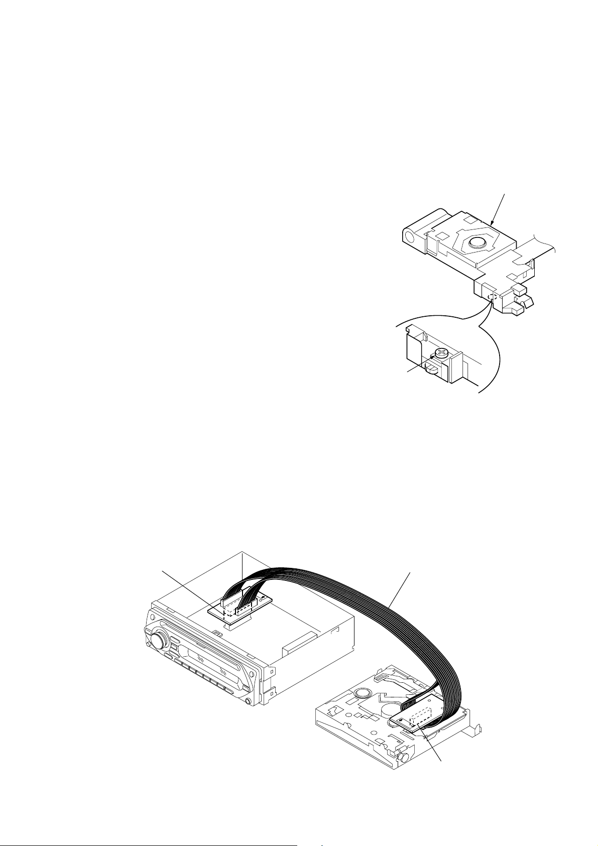
EXTENSION CABLE AND SERVICE POSITION
When repairing or servicing this set, connect the jig (extension cable)
as shown below.
• Connect the MAIN board (CNP301) and the SERVO board (CN1)
with the extension cable (Part No. J-2502-076-1).
MAIN BOARD
CNP301
J-2502-076-1
SERVO BOAR
CN1
3

CDX-GT06/CXS-GT06HP
TEST DISCS
Please use the following test discs for the check on the voltage and
the waveforms of the CD section.
YDES-18 (Part No. 3-702-101-01)
PATD-012 (Part No. 4-225-203-01)
Notes on CD-DA/CD-R/CD-RW
• CD playback:
You can play CD-DA and CD-R/CD-RW for audio use.
UNLEADED SOLDER
•
Boards requiring use of unleaded solder are printed with the leadfree mark (LF) indicating the solder contains no lead.
(Caution: Some printed circuit boards may not come printed with
the lead free mark due to their particular size.)
: LEAD FREE MARK
Unleaded solder has the following characteristics.
• Unleaded solder melts at a temperature about 40°C higher than
ordinary solder.
Ordinary soldering irons can be used but the iron tip has to be
applied to the solder joint for a slightly longer time.
Soldering irons using a temperature regulator should be set to
about 350°C.
Caution: The printed pattern (copper foil) may peel away if the
heated tip is applied for too long, so be careful!
• Strong viscosity
Unleaded solder is more viscous (sticky, less prone to flow)
than ordinary solder so use caution not to let solder bridges
occur such as on IC pins, etc.
• Usable with ordinary solder
It is best to use only unleaded solder but unleaded solder may
also be added to ordinary solder.
TABLE OF CONTENTS
1. GENERAL
Location of Controls and Basic Operations .................... 5
Connections ..................................................................... 5
2. DISASSEMBLY
2-1. Sub Panel Assy ................................................................ 8
2-2. CD Mechanism Block ..................................................... 8
2-3. Main Board ...................................................................... 9
2-4. Chassis (T) Sub Assy....................................................... 9
2-5. Roller Arm Assy .............................................................. 10
2-6. Chassis (OP) Assy ........................................................... 10
2-7. Optical Pick-up ................................................................ 11
2-8. SL Motor Assy (M902) ................................................... 11
2-9. LE Motor Assy (M903) ................................................... 12
2-10. Servo Board ..................................................................... 12
3. DIAGRAMS
3-1. Block Diagram –CD Section– ......................................... 13
3-2. Block Diagram –Main Section– ...................................... 14
3-3. Block Diagram –Display Section– .................................. 15
3-4. Circuit Boards Location .................................................. 15
3-5. Printed Wiring Boards –CD Mechanism Section– .......... 16
3-6. Schematic Diagram –CD Mechanism Section– .............. 17
3-7. Printed Wiring Board –Main Section– ............................ 18
3-8. Schematic Diagram –Main Section (1/3)– ...................... 19
3-9. Schematic Diagram –Main Section (2/3)– ...................... 20
3-10. Schematic Diagram –Main Section (3/3)– ...................... 21
3-11. Printed Wiring Boards –Key Section– ............................. 22
3-12. Schematic Diagram –Key Section– ................................. 23
4. EXPLODED VIEWS
4-1. Main Section.................................................................... 31
4-2. Front Panel Section ......................................................... 32
4-3. CD Mechanism Section (1) (MG-611XE-186//C) .......... 33
4-4. CD Mechanism Section (2) (MG-611XE-186//C) .......... 34
4-5. CD Mechanism Section (3) (MG-611XE-186//C) .......... 35
4-6. CD Mechanism Section (4) (MG-611XE-186//C) .......... 36
5. ELECTRICAL PARTS LIST .................................. 37
4
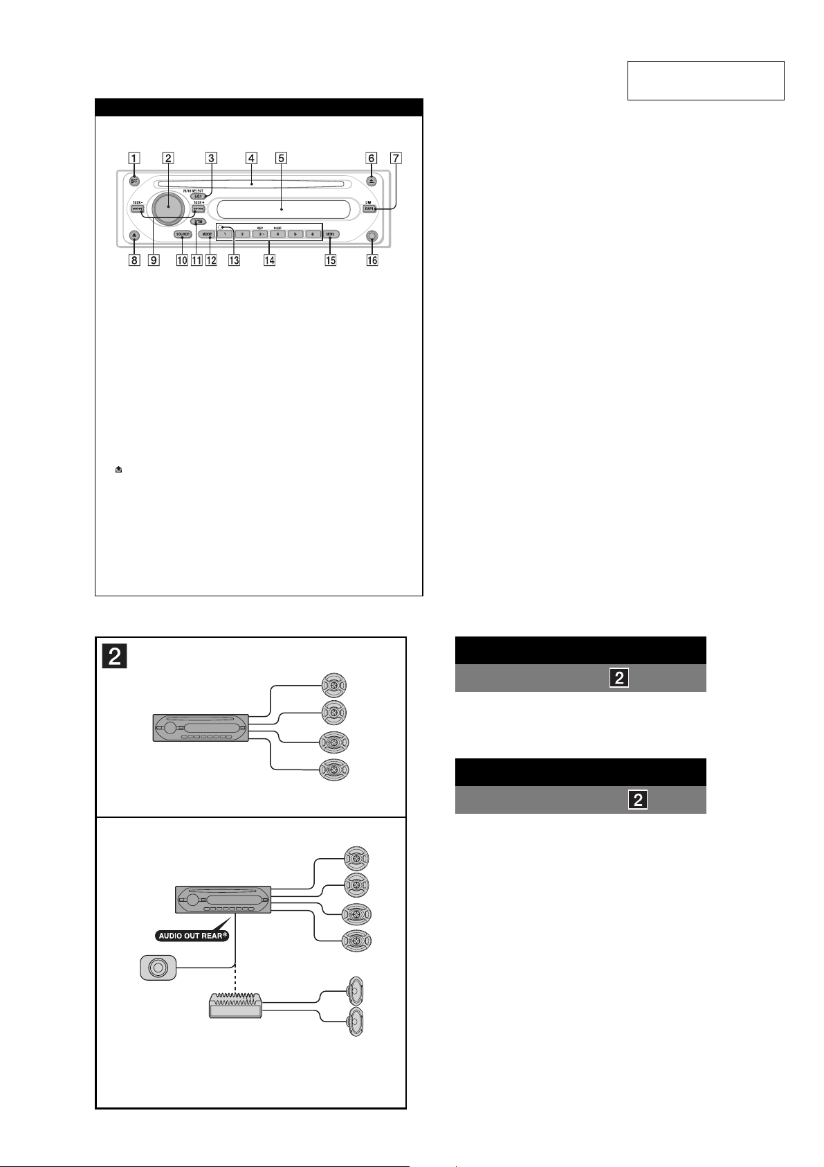
Location of controls and basic operations
Main unit
CDX-GT06
SECTION 1
GENERAL
CDX-GT06/CXS-GT06HP
This section is extracted
from instruction manual.
1 OFF button
To power off; stop the source.
2 Volume control dial/select button
To adjust volume (rotate); select setup items
(press and rotate).
3 EQ3 (equalizer) button
To select an equalizer type (XPLOD,
VOCAL, CLUB, JAZZ, NEW AGE,
ROCK, CUSTOM or OFF).
4 Disc slot
To insert the disc (label side up), playback
starts.
5 Display windo
6 Z (eject) button
To eject the disc.
7 DSPL (display)/DIM (dimmer) button
To change display items (press); change the
display brightness (press and hold).
8
(front panel release) button
9 SEEK –/+ buttons
CD:
To skip tracks (press); skip tracks
continuously (press, then press again within
about 1 second and hold); reverse/fastforward a track (press and hold).
Radio:
To tune in stations automatically (press);
fi nd a station manually (press and hold).
w
• CONNECTIONS
A
0 SOURCE button
To power on; change the source (Radio/CD/
AUX).
qa BTM button
To start the BTM function (press and hold).
qs MODE button
To select the radio band (FM/AM).
qd RESET button (located behind the front
panel)
qf Number buttons
CD:
(3): REP
To play the current track repeatedly.
(4): SHUF
To play the tracks in random order.
Radio:
To receive stored stations (press); store
stations (press and hold).
qg SENS button
To improve weak reception: LOCAL/
MONO.
qh AUX input jack
To connect a portable audio device.
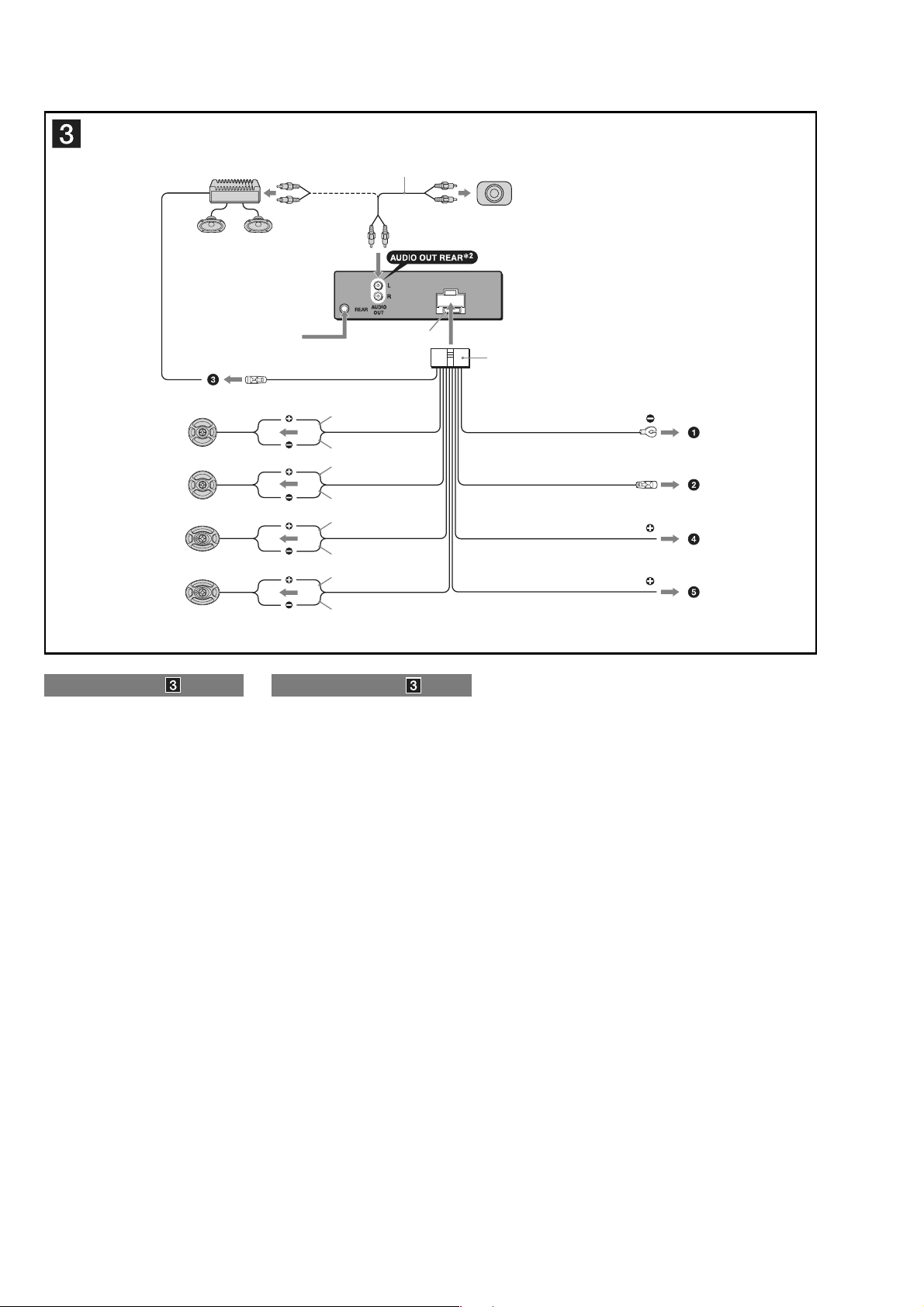
Connection
Connection example
Notes
(2-B)
•
Be sure to connect the ground lead before connecting the
amplifi er.
•
The alarm will only sound if the built-in amplifi er is used.
B
Active subwoofer
(not supplied)
Altavoz potenciador de
graves activo
(no suministrado)
*
AUDIO OUT SUB/REAR
Power amplifi er
(not supplied)
Amplifi cador de potencia
(no suministrado)
Rear speaker
(not supplied)
Altavoz posterior
(no suministrado)
Conexion
Ejemplo de conexiones
Notas
(2-B)
Asegúrese de conectar primero el cable de conexión a masa
•
antes de realizar la conexión del amplifi cador.
•
La alarma sonará únicamente si se utiliza el amplifi cador
incorporado.
5
CDX-GT06/CXS-GT06HP
Power amplifi er
(not supplied)
Amplifi cador de potencia
(no suministrado)
Rear speaker
(not supplied)
Altavoz posterior
(no suministrado)
from car antenna
desde la antena del automóvil
AMP REM
Max. supply current 0.3 A
Corriente máx. de alimentación de 0,3 A
Left
Izquierdo
Right
Derecho
Left
Izquierdo
Right
Derecho
1
*
L
R
BUS
AUDIO
IN
Fuse (10 A)
Fusible (10 A)
Blue/white striped
Con rayas azules y blancas
White
Blanco
White/black striped
Con rayas blancas y negras
Gray
Gris
Gray/black striped
Con rayas grises y negras
Green
e
Ve rd
Green/black striped
Con rayas verdes y negras
Purple
Morado
Purple/black striped
Con rayas moradas y negras
Active subwoofer
(not supplied)
Altavoz potenciador de
graves activo
(no suministrado)
2
Black
Negro
Blue
Azul
Corriente máx. de alimentación de 0,1 A
Red
Rojo
Yellow
Amarillo
1
*
2
*
For details, see the supplied Oper
1
*
2
*
Para obtener información, consulte el
ANT REM
Max. supply current 0.1 A
RCA pin cord (not supplied)
AUDIO OUT can be sw
or REAR.
Instructions.
Cable con terminales RCA
(no suministrado)
AUDIO OUT (Salida de audio) puede
cambiarse a SUB (Secundaria) o
REAR (Posterior).
itched to SUB
ating
manual de instrucciones suministrado.
Connection diagram
1 To a metal surface of the car
First connect the black ground lead, then connect the yellow
and red power input leads.
2 To the power antenna control lead or power
supply lead of antenna booster amplifi er
Notes
•
It is not necessary to connect this lead if there is no power
antenna or antenna booster, or with a manually-operated
telescopic antenna.
•
When your car has a built-in FM/AM antenna in the rear/side
glass, see “Notes on the control and power supply leads.”
3 To AMP REMOTE IN of an optional power
amplifi er
This connection is only for amplifi ers. Connecting any other
system may damage the unit.
4 To the +12 V power terminal which is energized
in the accessory position of the ignition key
switch
Notes
•
If there is no accessory position, connect to the +12 V power
(battery) terminal which is energized at all times.
Be sure to connect the black ground lead to a metal surface
of the car fi rst.
•
When your car has a built-in FM/AM antenna in the rear/side
glass, see “Notes on the control and power supply leads.”
5 To the +12 V power terminal which is energized
at all times
Be sure to connect the black ground lead to a metal surface of
the car fi rst.
Notes on the control and power supply leads
•
The power antenna control lead (blue) supplies +12 V DC when
you turn on the tuner.
•
When your car has built-in FM/AM antenna in the rear/side glass,
connect the power antenna control lead (blue) or the accessory
power input lead (red) to the power terminal of the existing
antenna booster. For details, consult your dealer.
•
A power antenna without a relay box cannot be used with this unit.
Memory hold connection
When the yellow power input lead is connected, power will always
be supplied to the memory circuit even when the ignition switch is
turned off.
Notes on speaker connection
•
Before connecting the speakers, turn the unit off.
•
Use speakers with an impedance of 4 to 8 ohms, and with
adequate power handling capacities to avoid its damage.
•
Do not connect the speaker terminals to the car chassis, or
connect the terminals of the right speakers with those of the left
speaker.
•
Do not connect the ground lead of this unit to the negative (–)
terminal of the speaker.
•
Do not attempt to connect the speakers in parallel.
•
Connect only passive speakers. Connecting active speakers (with
built-in amplifi ers) to the speaker terminals may damage the unit.
•
To avoid a malfunction, do not use the built-in speaker leads
installed in your car if the unit shares a common negative (–) lead
for the right and left speakers.
•
Do not connect the unit’s speaker leads to each other.
Note on connection
If speaker and amplifi er are not connected correctly, “FAILURE”
appears in the display. In this case, make sure the speaker and
amplifi er are connected correctly.
Diagrama de conexión
1 A una superfi cie metálica del automóvil
Conecte primero el cable de conexión a masa negro, y después
los cables con rayas naranjas y blancas, amarillo, y rojo de
entrada de alimentación.
2 Al cable de control de la antena motorizada
o al cable de fuente de alimentación del
amplifi cador de señal de la antena
Notas
•
Si no se dispone de antena motorizada ni de amplifi cador
de antena, o se utiliza una antena telescópica accionada
manualmente, no será necesario conectar este cable.
•
Si el automóvil incorpora una antena de FM/AM en el cristal
posterior o lateral, consulte “Notas sobre los cables de control
y de fuente de alimentación”.
3 A la toma AMP REMOTE IN de un amplifi cador
de potencia opcional
Esta conexión es sólo para amplifi cadores. La conexión de
cualquier otro sistema puede dañar la unidad.
4 Al terminal de alimentación de +12 V que
recibe energía en la posición de accesorio del
interruptor de la llave de encendido
Notas
•
Si no hay posición de accesorio, conéctelo al terminal de
alimentación (batería) de +12 V que recibe energía sin
interrupción.
Asegúrese de conectar primero el cable de conexión a masa
negro a una superfi cie metálica del automóvil.
•
Si el automóvil incorpora una antena de FM/AM en el cristal
posterior o lateral, consulte “Notas sobre los cables de control
y de fuente de alimentación”.
5 Al terminal de alimentación de +12 V que recibe
energía sin interrupción
Asegúrese de conectar primero el cable de conexión a masa
negro a una superfi cie metálica del automóvil.
Notas sobre los cables de control y de fuente de alimentación
•
El cable de control de la antena motorizada (azul) suministrará cc
de + 12 V cuando conecte la alimentación del sintonizador.
•
Si el automóvil dispone de una antena de FM/AM incorporada
en el cristal posterior o lateral, conecte el cable de control de
antena motorizada (azul) o el cable de entrada de alimentación
auxiliar (rojo) al terminal de alimentación del amplifi cador de
antena existente. Para obtener más información, consulte a su
distribuidor.
•
Con esta unidad no es posible utilizar una antena motorizada sin
caja de relé.
Conexión para protección de la memoria
Si conecta el cable de entrada de alimentación amarillo, el circuito
de la memoria recibirá siempre alimentación, aunque apague el
interruptor de encendido.
Notas sobre la conexión de los altavoces
•
Antes de conectar los altavoces, desconecte la alimentación de la
unidad.
•
Utilice altavoces con una impedancia de 4 a 8 Ω con la capacidad
de potencia adecuada para evitar que se dañen.
•
No conecte los terminales de altavoz al chasis del automóvil, ni
conecte los terminales del altavoz derecho con los del izquierdo.
•
No conecte el cable de conexión a masa de esta unidad al
terminal negativo (–) del altavoz.
•
No intente conectar los altavoces en paralelo.
•
Conecte solamente altavoces pasivos. Si conecta altavoces
activos (con amplifi cadores incorporados) a los terminales de
altavoz, puede dañar la unidad.
•
Para evitar fallas de funcionamiento, no utilice los cables de
altavoz incorporados instalados en el automóvil si la unidad
comparte un cable negativo común (–) para los altavoces derecho
e izquierdo.
•
No conecte los cables de altavoz de la unidad entre sí.
Nota sobre la conexión
Si el altavoz y el amplifi cador no están conectados correctamente,
aparecerá “Failure” en la pantalla. En tal caso compruebe la
conexión de ambos dispositivos.
6
SECTION 2
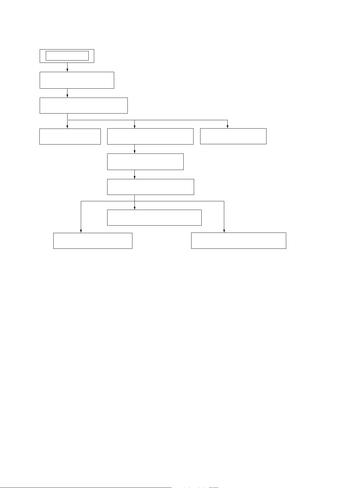
DISASSEMBLY
Note: This set can be disassemble according to the following sequence.
SET
2-1. SUB PANEL ASSY
(Page 8)
2-2. CD MECHANISM BLOCK
(Page 8)
CDX-GT06/CXS-GT06HP
2-3. MAIN BOARD
(Page 9)
2-7. OPTICAL PICK-UP
(Page 11)
2-4. CHASSIS (T) SUB ASSY
(Page 9)
2-5. ROLLER ARM ASSY
(Page 10)
2-6. CHASSIS (OP) ASSY
(Page 10)
2-8. SL MOTOR ASSY (M902)
(Page 11)
2-10. SERVO BOARD
(Page 12)
2-9. LE MOTOR ASSY (M903)
(Page 12)
7
CDX-GT06/CXS-GT06HP
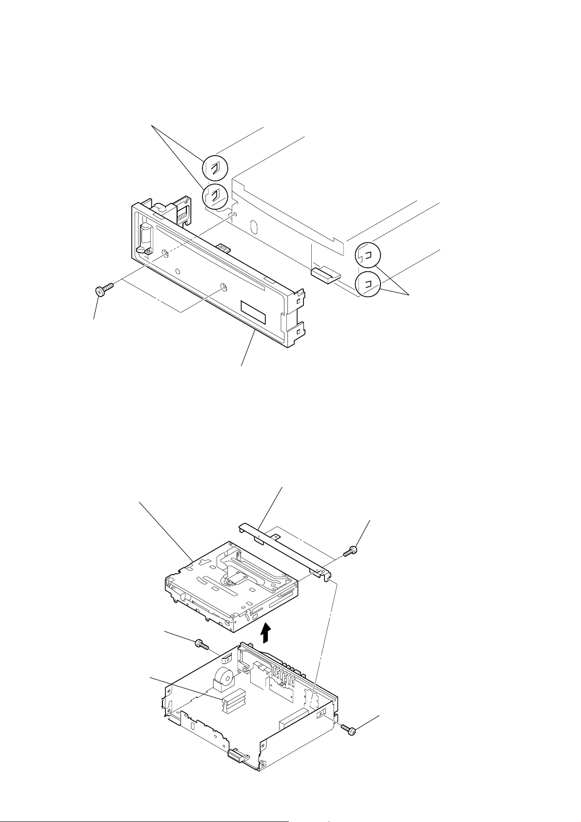
s
Note: Follow the disassembly procedure in the numerical order given.
2-1. SUB PANEL ASSY
3
two claws
2
two claw
1
two
screws
×
(+PTT 2.6
6)
2-2. CD MECHANISM BLOCK
7
CD mechanism block
4
sub panel assy
6
bracket (CD)
5
two
(+PTT 2.6
screws
×
4)
2
screw
(+PTT 2.6
4
CNP301
×
6)
3
1
screw
(+PTT 2.6
×
6)
8
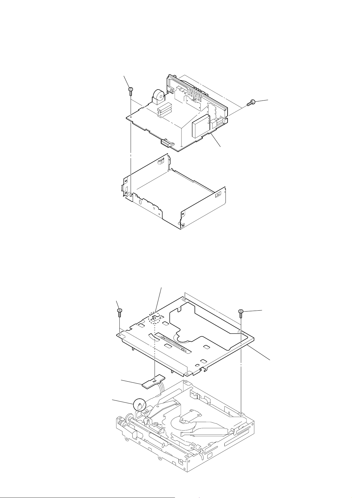
2-3. MAIN BOARD
)
y
1
three
(+BTT 2.6
screws
×
CDX-GT06/CXS-GT06HP
5)
2
two
screws
×
8
3
MAIN board
(+PTT 2.6
2-4. CHASSIS (T) SUB ASSY
2
two
screws
(+P 1.7
5
SENSOR board
3
claw
×
2.2)
4
claw
1
two
screws
×
(+P 1.7
6
2.2)
chassis (T) sub ass
9
CDX-GT06/CXS-GT06HP
)
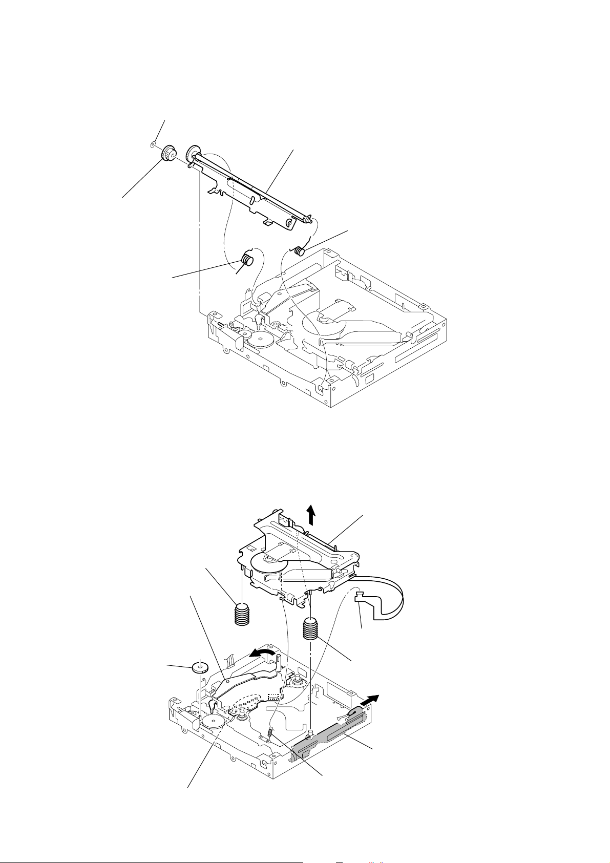
2-5. ROLLER ARM ASSY
3
4
gear (RA1)
1
spring (RAL)
washer (1.1-2.5)
5
roller arm assy
2
spring (RAR)
2-6. CHASSIS (OP) ASSY
9
compression spring (damper)
4
gear (LE1)
lever (D)
5
7
0
chassis (OP) assy
1
optical pick-up (16 core
(CN2)
8
two compression springs
(damper)
6
slider (R)
10
2
Remove the six solders.
3
tension spring (KF60)
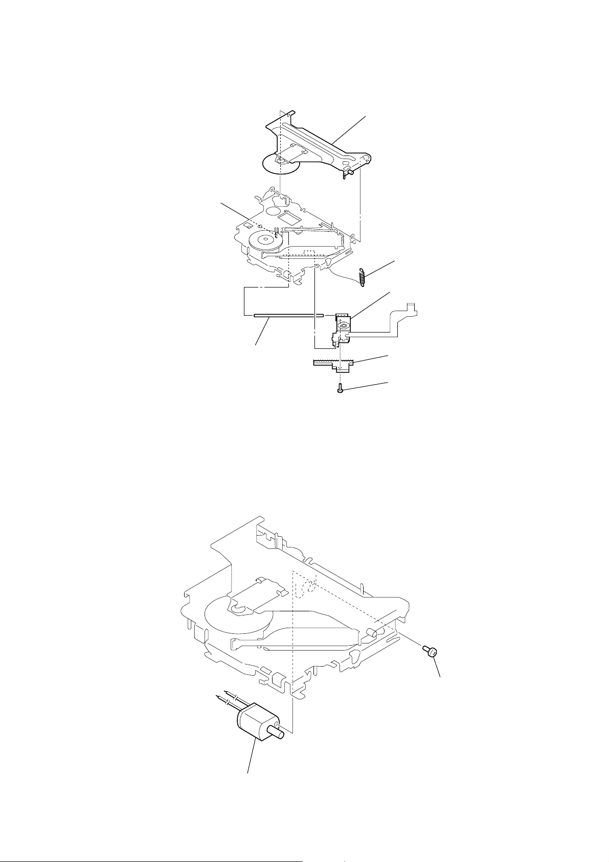
2-7. OPTICAL PICK-UP
1
tension spring (CHKG)
2
chucking arm sub assy
3
screw
(+B 1.4
×
5)
4
rack (SL)
5
claw
6
main shaft
7
optical pick-up
1
screw
(+P 1.4
×
1.8)
2
SL motor assy (M902)
CDX-GT06/CXS-GT06HP
2-8. SL MOTOR ASSY (M902)
11
CDX-GT06/CXS-GT06HP
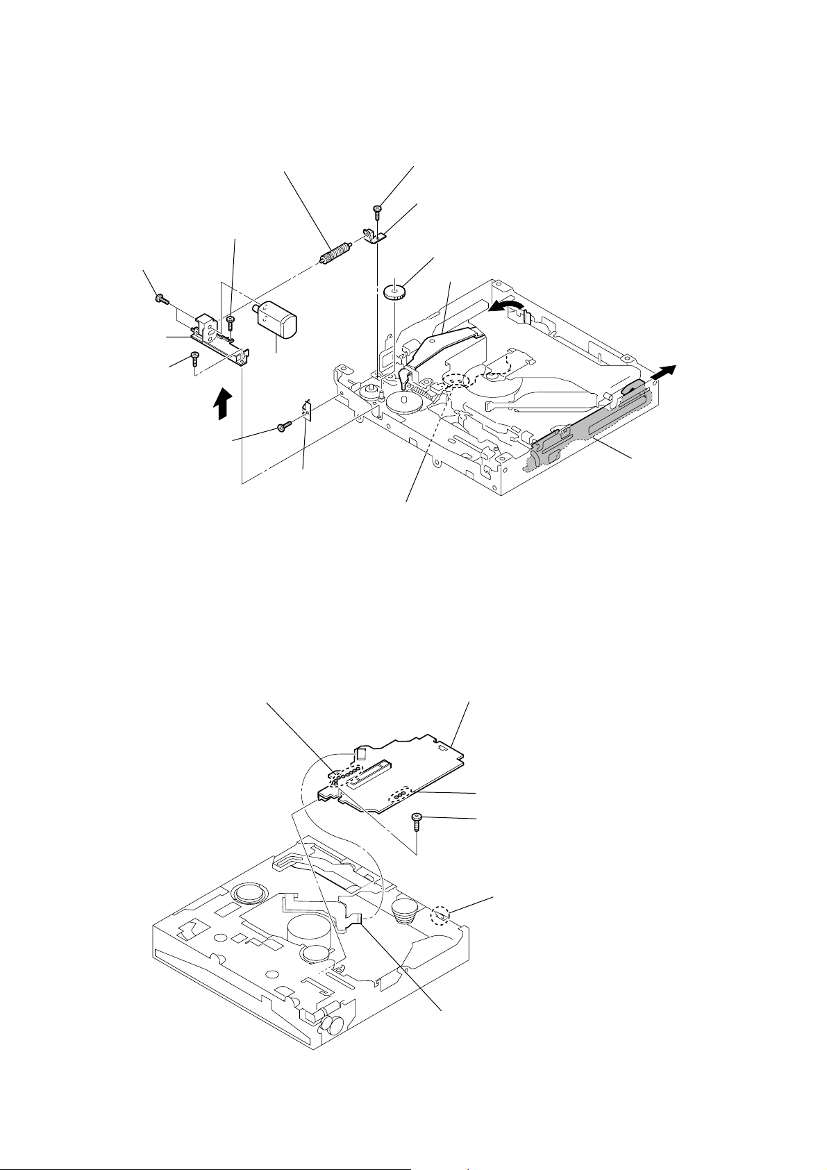
2-9. LE MOTOR ASSY (M903)
0
qd
two toothed lock
)
(+M 1.4
bracket (LEM-N)
qa
screw
×
(+M 1.7
2.5)
5
screws
screw
(+P 1.7
qs
×
2.2)
screw
(+M 1.7
qf
9
gear (LE) assy
×
2.5)
LE motor assy (M903)
6
leaf spring (LE)
7
screw
(+M 1.7
8
bearing (LEB-N)
gear (LE1)
2
lever (D)
×
2.5)
3
4
slider (R)
2-10. SERVO BOARD
1
Remove the eight solders.
1
Remove the two solders.
6
SERVO board
2
Remove the three solders.
4
toothed lock
(M 1.7
5
claw
×
screw
2.5)
12
3
optical pick-up (16 core)
(CN2)
SECTION 3
DIAGRAMS
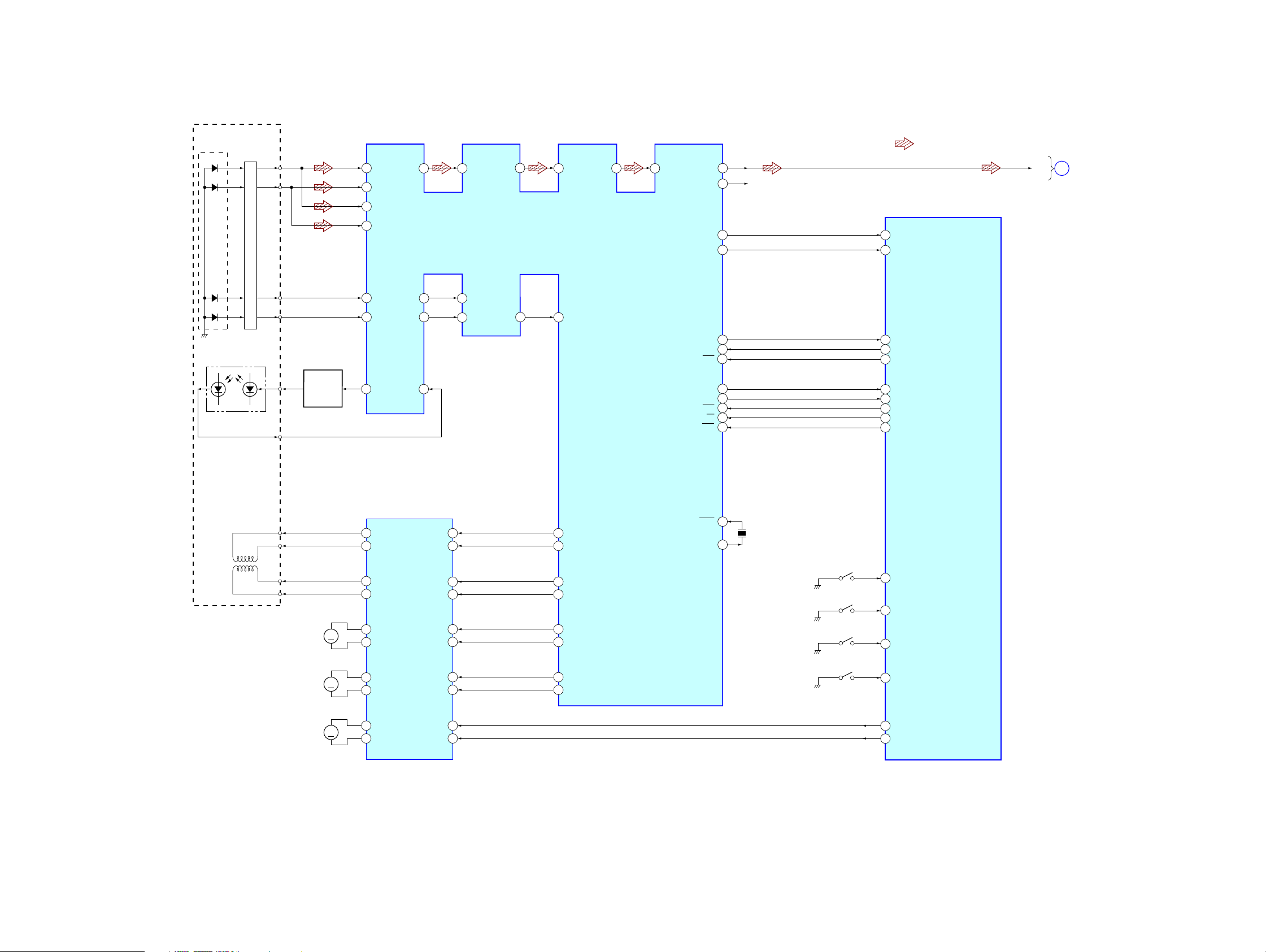
3-1. BLOCK DIAGRAM — CD SECTION —
DETECTOR
PD1
PD2
PD1
PD2
I-V AMP
RFO
A
82
B
84
C
83
D
85
CDX-GT06/CXS-GT06HP
• R-ch is omitted due to same as L-ch.
• Siganal Path
: CD PLAY
AGCO
78
AGCI
77
76
RF AMP,DIGITAL SERVO,
DIGITAL SIGNAL PROCESSOR
71
IC1
EFM
RFI
68
ASY
69
LOUT
ROUT
LMUTE
RMUTE
20
16
R-CH
30
29
CD_MUTE-L
94
CD_MUTE-R
93
CD-L
MAIN
A
SECTION
(Page 14)
E
F
LASER DIODE
PICK-UP BLOCK
(KSS1000E)
2-AXIS DEVICE
(FOCUS)
(TRACKING)
PD LD
OPTICAL
PD
FCS+
FCS–
TRK+
TRK–
E
F
LD
AUTOMATIC
POWER
CONTROL
M902
(SLED)
Q1
M
87
86
1
FOCUS/TRACKING COIL DRIVE,
11
12
13
14
15
16
FEO
E
F
LD
SLED/SPINDLE/LOADING
VO2–
VO2+
VO1–
VO1+
VO4+
VO4–
93
TEO
96
2
PD
MOTOR DRIVE
IC2
OPIN2+
OPIN2–
OPIN1+
OPIN1–
OPIN4+
OPIN4–
FE–
92
TE2
TE–
95
5
6
2
3
27
26
97
TEC
98
12
SO
13
SI
11
SCK
6
RFOK
7
INTQ
10
STB
9
A0
8
RST
23
FD+
52
FD–
53
TD+
54
TD–
55
SD+
56
SD–
57
XTAL
XTAL
24
X1
16.9344MHz
SW1
(DOWN)
SW2
(SELF)
SW3
(DISC IN)
CD_SI
18
CD_SO
19
CD_SCK
20
CD RFOK
89
CD INTQ
55
CD_STB
92
CD_A0
91
CD RST
90
CD_DSW
99
CD_SELFSW
96
CD_INSW
95
SYSTEM CONTROL
IC501 (1/3)
CDX-GT06/CXS-GT06HP
M901
(SPINDLE)
M903
(LOADING)
OPIN3+
OPIN3–
FWD
REV
24
23
1
28
17
M
M
VO3+
18
VO3–
10
VOL+
9
VOL–
MD+
58
MD–
59
SW4
(LIMIT)
100
97
98
CD_LIMIT
CD LM LO
CD LM EJ
13 13
CDX-GT06/CXS-GT06HP
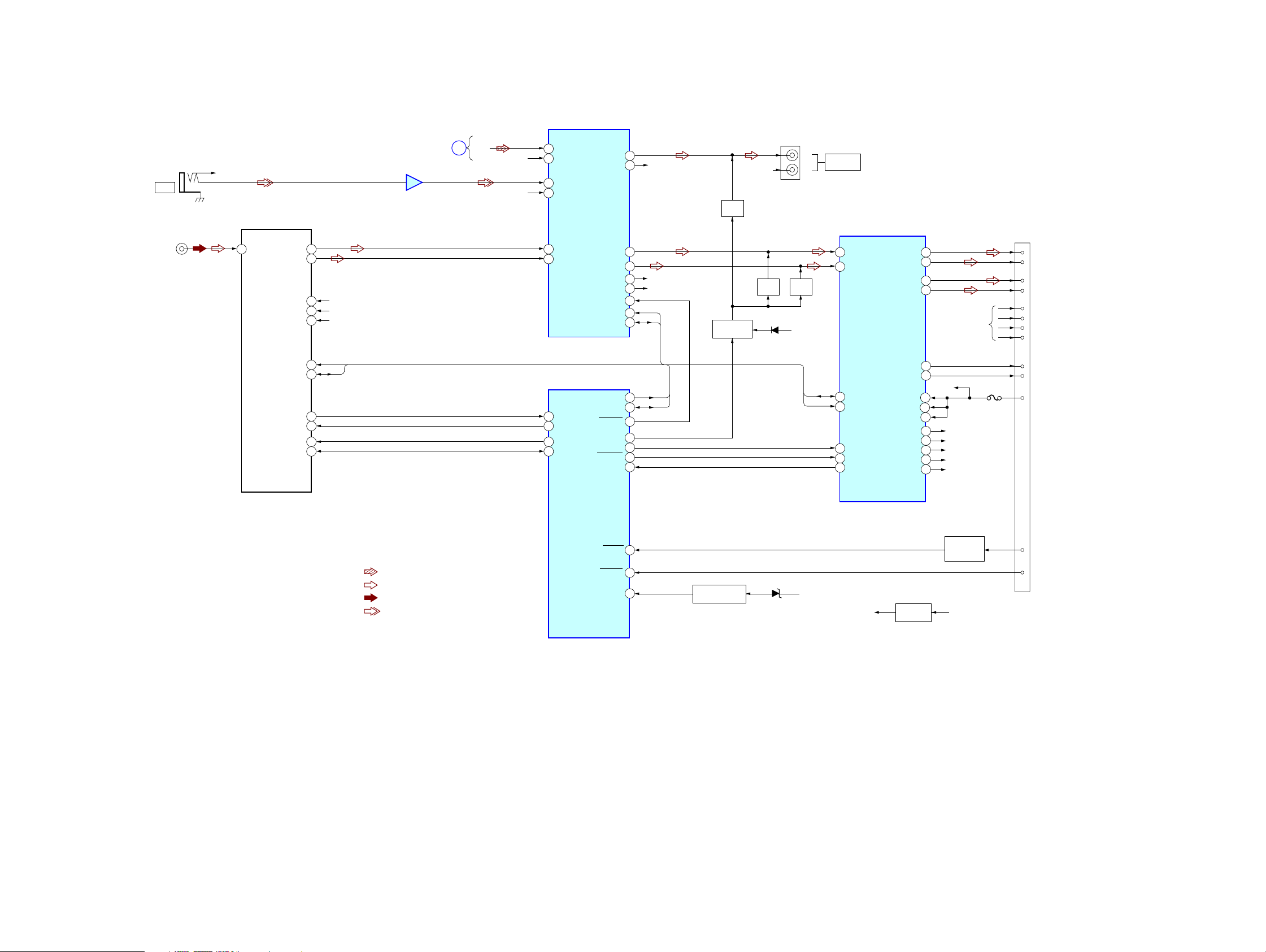
3-2. BLOCK DIAGRAM — MAIN SECTION —
ELECTRONIC VOLUME
IC401
J901
AUX
J1
(ANTENNA)
R-CH
1
ANT
TU1
(TUNER UNIT)
TU VDD
E2P VDD
TU-SCL
TU-SDA
S-METER
TU MUTE
E2P SCL
E2P SDA
L-CH
R-CH
VCC
10
11
15
13
14
16
17
4
3
6
7
AUDIO+8.3V
TU+5V
BU+3.3V
SCL
SDA
(Page 13)
AUX
BUFFER
IC901
CD
SECTION
CD-L
A
R-CH
R-CH
9
CD LCH
8
CD RCH
5
AUX LCH
3
AUX RCH
7
TU LCH
6
TU RCH
SYSTEM CONTROL
39
VSM
12
TU ATT
25
EEP CKO
24
EEP SIO
OUT SUB-L
OUT SUB-R
IC501 (2/3)
OUT FL
OUT RL
OUT FR
OUT RR
MUTE
SCL
SDA
I2C CKO
I2C SIO
VOL ATT
ATT
BEEP
AMP STB
DIAG
17
18
23
22
25
24
29
30
31
33
34
9
86
5
26
8
R-CH
R-CH (FRONT)
R-CH (REAR)
SCL
SDA
SCL
SDA
MUTE
Q481
MUTE DRIVE
Q478,479
R-CH
MUTE
Q441
D479
MUTE
Q461
BATT
J330
L
AUDIO OUT
REAR
R
I2C-BUS
CONTROLLED
POWER AMP/
MULTIPLE
VOLTAGE
REGULATOR
SDA
SCL
IC750
12
IN FL
11
IN RL
2
SDA
4
SCL
16
BEEP
22
STB
25
DIAG
OUT FL+
OUT FL–
OUT RL+
OUT RL–
AMP-REM
ANT-REM
VP1
VP2
AUDIO8.3V
B.UP+B
SERVO3.3V
MECHA6V
PANEL+B
5
3
9
7
R-CH
29
27
BATT
35
VP
20
6
30
AUDIO+8.3V
37
BU+3.3V
31
SERVO+3.3V
33
MECHA+6V
34
PANEL+B
FU601
CN601
10
12
11
16
1
FL+
9
FL–
2
RL+
RL–
4
FR+
FR–
3
RR+
RR–
5
AMP-REM
6
ANT-REM
BATT
• R-CH is omitted due to same as L-CH.
• Signal Path
: CD PLAY
: FM
: AM
: AUX
ACC IN
TEST IN
BU IN
ACCESSORY
72
73
54
BATTERY CHECK
Q580-582
D580,581
BATT
TU+5V
TU+5V REG
Q1
CHECK
Q631
AUDIO+8.3V
7
ACC
15
TEST
CDX-GT06/CXS-GT06HP
1414
 Loading...