


CDU701
CD-ROM Drive Unit
取扱説明書
User’s Guide
3-864-931-01(1)
Guide de l’utilisateur
Benutzerhandbuch
Manual del usuario
Gebruikershandleiding
Användarhandbok
Manuale dell’utente
Käyttäjän ohjekirja
Brugsanvisning
Brukerhåndbok

• MS-DOSは米国マイクロソフ ト社の登録商標です。
• IBM PC、PC/XT、ならびにPC/ATは米国 International Business
MachinesCorporationの登録商標です。
• HPVectraは米国ヒューレットパッカード社の登録商標です。
• MolexはMolex社の登録商標です。
• AMPはAMP社の登録商標です。
2

目次
はじめに
特長 .................................................................................................................4
必要なソフトウェア .....................................................................................5
システム構成 .................................................................................................5
各部の名称と働き
前面 .................................................................................................................6
後面 .................................................................................................................7
使用上の注意
ドライブの取り付けかた
準備 .................................................................................................................9
ジャンパーの設定 .......................................................................................10
コンピューターカバーの取りはずし .......................................................11
ドライブベイを空ける ...............................................................................12
ドライブの取り付け ...................................................................................13
接続 ...............................................................................................................14
コンピューターを再び組み立てる ...........................................................17
ソフトウェアドライバーのインストール
インストール方法 .......................................................................................18
18
4
6
8
9
使いかた
ドライブを使う ...........................................................................................19
ディスクを取り出す ...................................................................................21
ロックの使いかた .......................................................................................22
主な仕様
19
24
目次
3

はじめに
特長
CDU701はIBM-PC、HPVectra、またはこれらの互換機で使用するために設
計された内蔵CD-ROM(CompactDiskRead-OnlyMemory)ドライブユニッ
トです。1枚のCDに記録されている最大650Mバイトの デジタル データを読 み
出すことができます。
CDU701は次のような特長を備えています。
全般的な特長
• 51/4インチ、ハー フハイトの 内 蔵ドライブです。
• ATAPI準拠(SFF-8020)128kバイトバッファメモリーを装備しています。
• キャディ ーな しでディ スクをロー ドできる、オーデ ィオCD 仕様のディスク トレ
イで す 。
• ディスクを自 動 的にロード/イジェ クトします。手動によるイジェ クトも可能で
す。
• ケースは気密構造になっています。
サポートするディスクフォーマット
• CD-ROM、CD-ROMXA、CD-I、およびCD-IReadyフォーマットのディスク
と、 CD-EXTRAおよびCDTEXTディスクの読み出しができます。
• PHOTO-CDを含むCD-BRIDGEフォーマットのデータの読み出しができま
す。
• 標準 CD-DigitalAudioディスクの読み出しができます。
• VideoCDディス クの読み出しができます。
性能
• 4倍速、8倍速、および最大32倍速動作モード をサポートし、いずれのモー
ドでもリア ルタイムエラー訂正機能をサポートしています。
• 高速アクセスにより 読み出しを高速に行う ことが できます。
オーディオ機能
• 16ビット デジタルオーディオ信号をATAイ ンターフェース経由 で出 力します。
• オーディオCD の再生 のために、オーディオライン出力とヘ ッドフォンジャッ
クを装備 してい ま す。
ご注意
CDU701はADPCMオーディオ回路を装備していません。そのため、CD-
ROMXAおよびCD-I互換オーディオモードをサポー トしていません。
また、本製品はCD-Iグラフィックデコード機能をサポートしていません。この
機能が必要なときは、システムに組み込んでください。
はじめに
4

必要なソフトウェア
ご使用のオペレーティングシステムがMS-DOS/Windows 3.1の場合、CDRO M ディス クのデータにアクセスするには、適切なデバイスドライバーと
MSCDEX(ホストアダプターに付属)がお手持ちのコンピューターにインストー
ルされている必 要があり ます。詳し く は、ホストアダプ ターのマニュアルを参
照してく ださい。
CD-ROMディスクのデ ータを使用するために必要なアプリケーションソフ トウェ
アは、必要とするデータの種類とフ ォ ーマ ット によって異なり ます。CD-ROM
ディ スクに付属の マニュアルを参照 してください。
システム構成
このCD-ROMドライブユニットを使用す るには、次のような機器が必要です。
• パーソナルコンピューター(IBM-PC、PC/XT、PC/AT、HPVectra、または
これらの互換機)
• IDEホストアダプター(ATA準拠)
• フロッ ピーディ スク ドライブ
• IDEインターフェースケーブ ル( 40 ⇔ 40ピンフラット ケーブル)
• ソフ トウェア(デ バイスドライバー 、およびユーティリティ)
次に システム構成の例を示します。
ソフトウェア
フロッピー
ディスク
ドライブ
CD-ROM
ドライブ
オーディオケーブル
ホストコンピューター
ホストアダプター
はじめに
5

各部の名称と働き
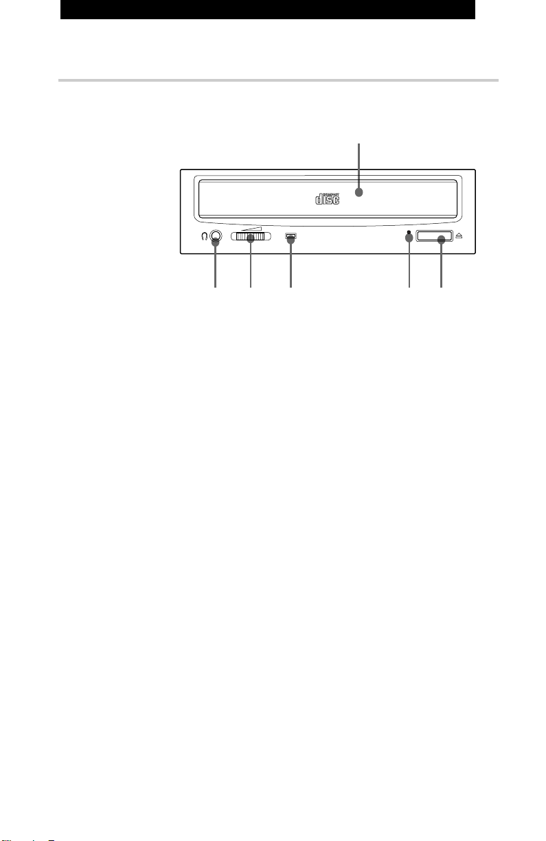
前面
2
1 ディスクトレイ
CD-ROMディスクをこの トレイ に乗せて入れます。
2 ヘッドフォンジャック
ステレオヘッ ド フォンをこ こに差し込みます。アナログオーディ オ信 号
が出力されます。
1
34 56
各部の名称と働き
6
3 ボリューム
ヘッ ド フォ ンジャ ック2から出力される音量を調節します。
4 ビジーインジケーター
この黄色のインジケーターは、 ドライブ ユ ニッ トが次のような状態である
ことを知らせるために点灯または点滅します。
•点灯: TOC(TableofContents)およびシークデータの読み出し、
またはオーディオ再生中
•点滅: ディスク トレイの動作中
5 緊急イジェクト穴
ディ スク トレイ がイジェクトボタン 6を押 してもソ フトウェアからも開かなく
なったときに使用し ま す。 ペーパーク リップなど先の細いものをこの穴
に押し込んでトレイ を開 きます。
6 イジェクトボタン
ディ スク トレイを開閉するときに使用します。

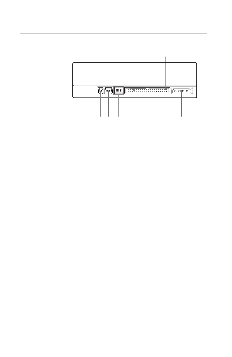
後面
ピン
1
1
2
45
3
1 使用しません。
2 オーディオ出力コネクター
アナログオーディ オ信号が出力されます。
3 バス設定ジャンパーブロック
詳しく は 10 ページを参 照してく ださい。
4 インターフェースコネクター
接続ケーブルを使って IDEホストアダプターに接続します。
(IDEバス)
5 電源コネクター
ホストコ ンピューターの 電源に接続します。
各部の名称と働き
7

使用上の注意
■ 設置場所について
• 次のような場所に設置しないでください。
• 電源ケーブルに力を加えないでください。ド ライブを保護するためにキーが
付いていて、挿入の向きが決まっています 。
■ 操作について
• 動作中にドライ ブを移動しないでく ださい。デー タ エ ラ ー や、光ピックアップ
の損傷を引き起こすこ とがあ り ます。
• 急激な温度変化は避けてください。ドライブ内のレンズ に結露すること があ
ります 。ドライブの動作中に周囲の温度が急に上がった場合は、ドライブの
使用を中止して、1時間以上電源を入れたままにしておいてから、電源を
切ってく ださい。温度が急に上が った後すぐにドライ ブを使用することは故
障の原因となります。
−湿気の多い ところ
−温度の高い ところ
−ほこりの多いところ
−機械振動のあるところ
−直射日光の当たるところ
■ 輸送について
使用上の注意
8
•ドライブを移動するときはディスク トレイ を閉じておいてください。
• 梱包材は保存しておいてください。ド ライブを別の場所に輸送する 必要が
あるときに、元の梱包材を使うと安全に輸送できます。

ドライブの取り付けかた
ここでは、 IDEホストアダプター(ATA準拠)を使用してお手持ちのコンピュー
ターにCD-ROMドライブユニットを取り付けるための手順について説明しま
す。
CDU701を直接PCのIDEポートに 接 続し た いときは 、コンピューターの製造
元にご相談ください。
準備
次のような部品と道具が必要です(ドライブには付属していません)。
• マイ ナスドライバー
• 3mm径6mm長のネジ4本
• 取り付け トラ ックがある場合は、 取り付けガイドレール2本
コンピューターの電源を切り、後面のケーブルを抜いて作業領域 を広く取っ
てく ださい。取り付けがすべて終わるまでは、コンピューターの電 源を入れな
いでください。
ドライブの取り付けか た
9

ジャンパーの設定
ドライブの後面のジャンパーをコンピューターのコンフィギュレー ションにあわ
せて設定し ます。
工場出荷時にはジ ャンパーはイラス トの"MASTER"の位置に セットされていま
す。
CSEL
SLAVE
MASTER
ご注意
•ドライブ番号の指定は通常ジャンパーピンをMASTERピンかSLAVEピンの
どち らかに差し込んで設定します。
• IDEカードにCDU701とハードディスク ドライブをデイジーチェ ー ン接続する
ときは、ハードディスク ドライブをMASTERに、CDU701をSLAVEに設定し
てく ださい。
• CDU701のみをIDEカードに接続する場合は、CDU701をMASTERに設
定してく ださい。
ドライブの取り付けか た
10
パー ソ ナルコンピュ ーターの機種によっ ては、MASTER/SLAVEの代わりに
CSELを使用するものもあります。この場合は、ジャンパーをMASTERおよび
SLAVE から取り去り、CSELに取り付けます。インターフェースコネクターの
CSEL信号がLowに設定されている場合は、ドライブはDRIVE0となります。
Highに設定されている場合は、DRIVE1となります。
詳しく は、お手持ちのコ ンピュ ータ ーの製造元か、IDEカードの製造元または
ディ ーラーにご相 談ください。

コンピューターカバーの取りはずし
1 コ ンピュー ターの後面にプラ ス ティックパネルがプラスティックのフック
で取り付けられている場合は、それを取りはずします。
コンピューター
2 カバーを止めているネ ジ を外します。
プラスティックパネルを外す
後部プラスティックパネル
カバー取り付けネジ
ネジを外す
3 カバーを外します。
コンピューターのカバーを外す
ドライブの取り付けか た
11

ドライブベイを空ける
1 フロッ ピーディ スク ドライ ブと下部 ドラ イブベイのカバーパネルを止めて
いるネジとブラケットを外します。
ネジとブラケットを外す
2 フロッ ピーディ スク ドライ ブからケーブルを抜きます。
フロッピーディスク
ドライブ
下部ドライブベイの
カバーパネル
フロッピーディスク
ドライブ
ドライブの取り付けか た
12
3 フロッ ピーディ スク ドライ ブとカバープレートを取り はずします。
フロッピー
ディスクドライブ
カバープレート

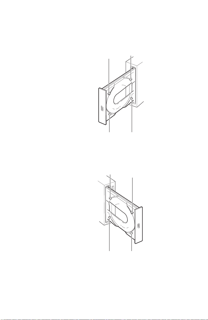
ドライブの取り付け
取 り付けガイド レ ールが必要な場合は、フロッ ピーディ スク と同じよ うにガイド
レールを ドライ ブに取 り付けてから、ドライブを ドライ ブベイに入れます。取り付
けガイド レールが必要でない場合は、ドラ イ ブをネ ジで取り付けます。
ドライブを下部ドライブベイに差し込む
ドライブの取り付けか た
13

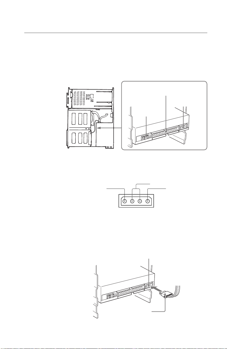
接続
ドライ ブに次のよう なコンピューターのコネクタ ーを接 続します。
• 電源コネクター
• オーディオ出力コネクター(オーディオ機器を接続する場合のみ)
• インターフェースコネクター
インターフェースコネクター
■ 電源コネクター
オーディオ出力
コネクター
電源コネクター
ピンの割り当ては以下のとおりで す。
GND
+5 V DC
+12 V DC
コネクタ ーの向きをあわせてから、電源ケ ーブルのプラ グを電源コネクターに
差し込み、 しっかり押し入れます。
ご注意
誤った接続をするとドライブが損傷するうえに、保証が無効になります。
電源コネクター
ドライブの取り付けか た
14
電源ケーブル
ピン接続ケーブル
(4
)

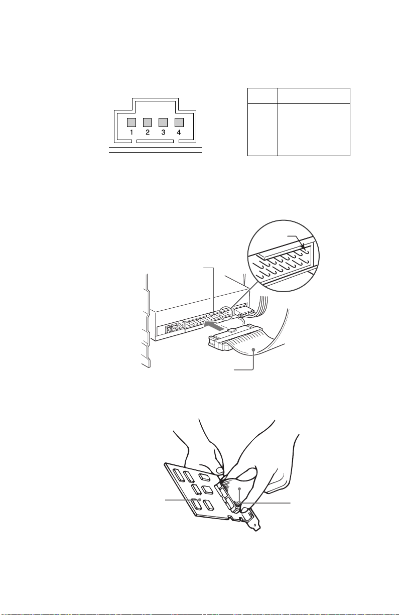
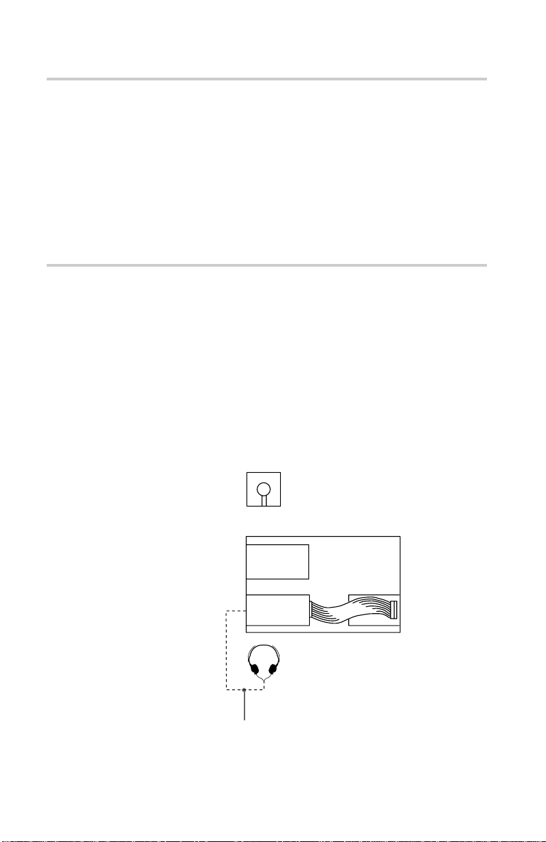
■ オーディオ出力コネクター
ピンの割り当ては以下のとおりで す。
■ インターフェースコネクター
1 インターフェースケーブル の一 方 の端をイ ンター フェ ース コネク タ ーに
しっかりと差し込みます。
インターフェースコネクター
ピン オーディ オ信号
1R信号
2接地
3接地
4L信号
ピン1
インターフェース
ケーブル
2 ケーブルのもう一方の端をホストアダプターに取り付けます。
ホストアダプター
インターフェース
ケーブル
ドライブの取り付けか た
15

■ ホストアダプターの取り付け
ホストアダプターを お手持ちの コン ピューターの空いている 拡張スロ ットのひと
つに取り 付け ます。取り付 けと設定の具体的な手順については、ホストア ダ プ
ターに付属の取扱説明書を参照してください。
拡張スロットのひとつに
ホストアダプターを
取り付ける
ドライブの取り付けか た
16

コンピューターを再び組み立てる
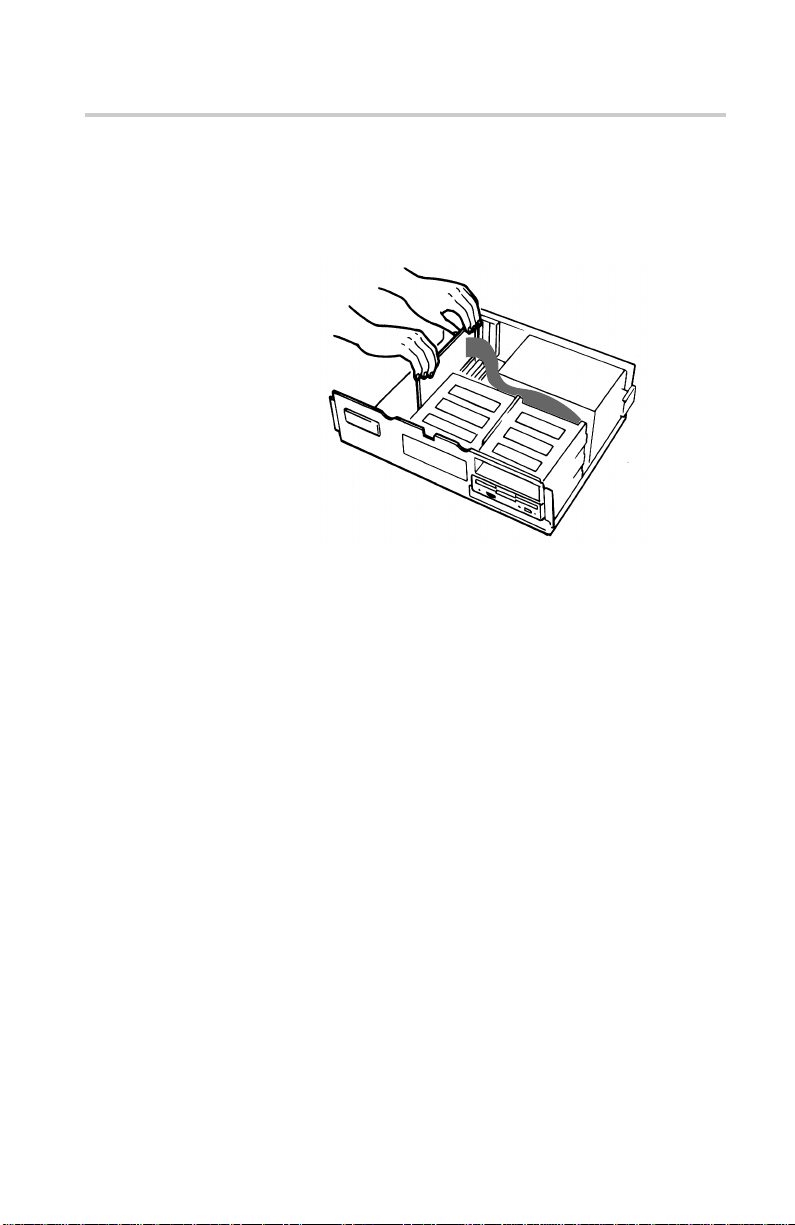
1 フロッ ピーディ スクドライブを再び上部ドライブベイに取り付けます。
フロッピーディスクドライブを
再び取り付ける
2 フロッ ピーディ スクドライブのインターフェースケーブルを再び接 続しま
す。
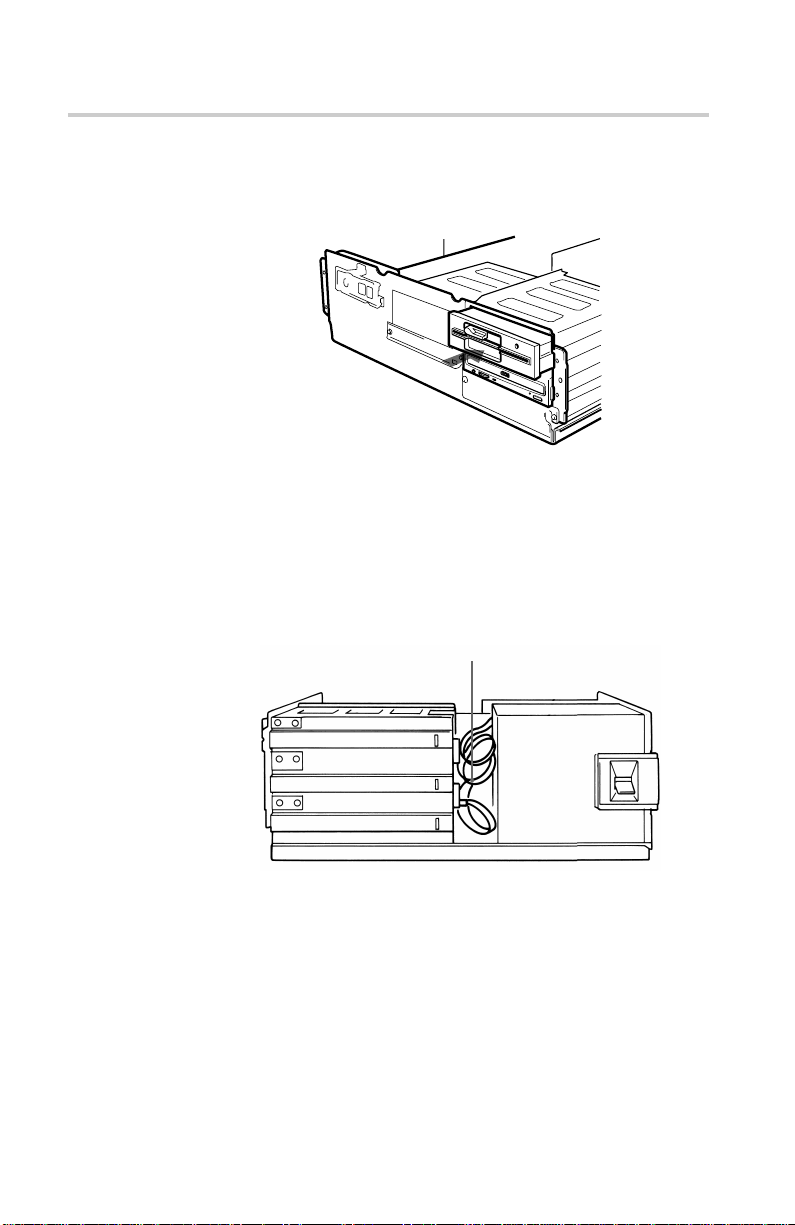
3 ネジとフロントブ ラケットを元の場所に固定し ます。
4 ケーブルをドライブの後ろの隙間にまとめて入れ込ます。ケーブルが電
源モジュールの上部にはみ出 さ ないよ うに してください。
ケーブルをまとめて入れる
電源
5 次のことを確認してか ら、コン ピ ュー ターカ バーをスラ イドさせ て 入 れ 、
コンピューター後部からネジで固 定します。
•ドライブ と コンピュ ー ターの接続は正しいか?
• ジャ ンパーは正しい位置に設定されているか ?
6 上記の質問のどちらか に 対して「いいえ」の場合は、後面のプラス
ティ ックパネルを 外し て、もう一度取り付けの説明を参照してください。
ドライブの取り付けか た
17

ソフトウェアドライバーのインストール
パッ ケー ジに付属しているインストール ディスクには2つ のソフ トウェアが 含 ま
れてい ます。
• インストーラー
• MS-DOS/Windows3.1用デバイスドライバー
ご注意
MS-DOS およびWindows3.1上でCDU701を動作させるには、Microsoft
CD-ROMExtension(MSCDEX)またはこれと同等のファイルと、ソニー製デ
バイスドライバーの両方がが必要です。
したがって、インストー ル ディスクをセッ トする 前に、ハードディスクのDOSディ
レクトリ(C:¥DOS)内にMSCDEXがあるかどうか確認してください。MSCDEX
は最新のMS-DOS(Ver.6.2)には含まれていますが、お持ちでない場合はコ
ンピューターの販 売店を通して入手 する必 要があり ます。
MSCDEX がすでにドライブのC:¥DOSにある場合、インストーラーは
AUTOEXEC.BAT ファイルでMSCDEXを、CONFIG.SYSファイルでデバイス
ドライバーをロー ドします。
インストール方法
ソフ トウェア ド ラ イバーのインストー ル
18
DOSプロンプトでA:¥と入力します(Aドライブがアクティブ)
>A:¥
インストー ル ディスクをフロッピー ディスク ドライ ブAに挿入し、"install"と入力
します。
>A:¥install
(Enter) キー を押します。
インストールが終了すると、CONFIG.SYSとAUTOEXEC.BATファイルに次の
行が追加されます。
CONFIG.SYS:
Device=C:¥DEV¥ATAPI_CD.SYS¥D:¥mcscd000¥I:O
AUTOEXEC.BAT:
C:¥DOS¥MSCDEX.EXE¥D:mscd000¥M:12¥V

使いかた
ドライブを使う
ここでは、ドライ ブを動作させる 方法と 、ディ ス クの取り出 し か たについて説明
します。
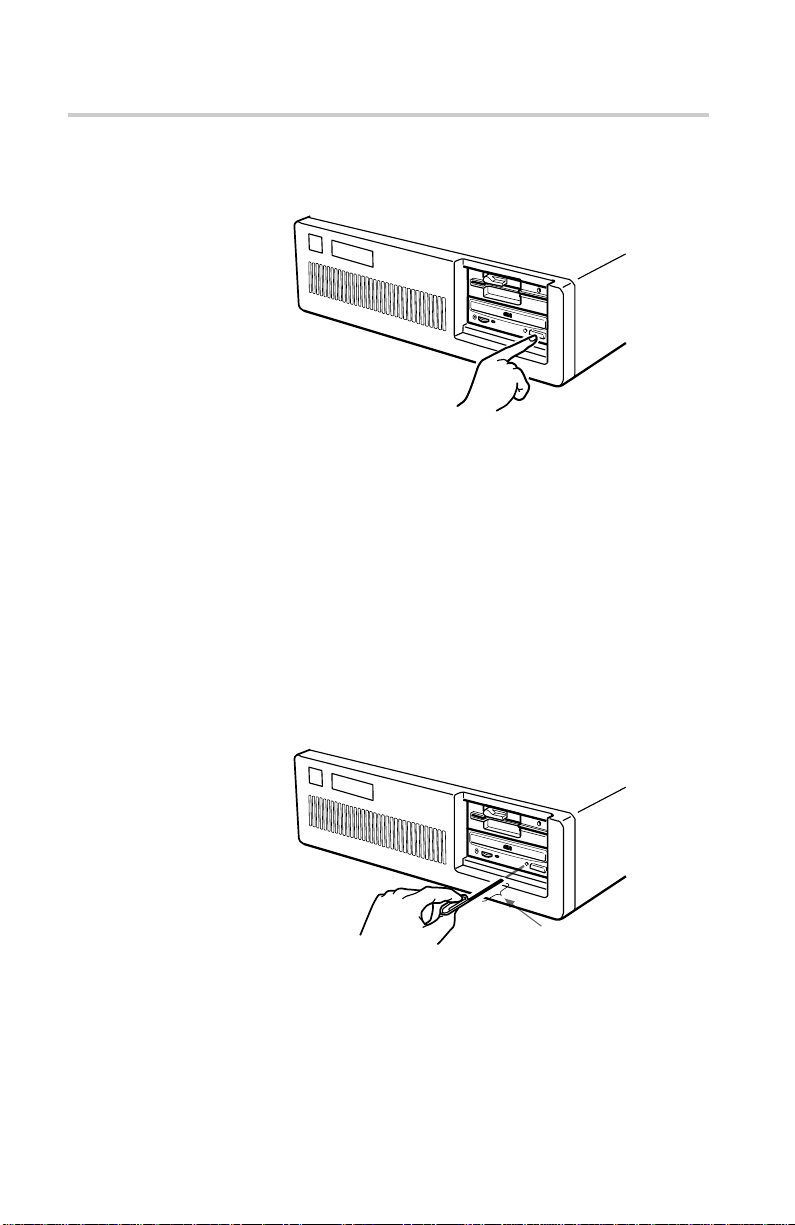
1 コンピューターの電源を入れます。
2 イジェクトボタンを 押します 。
トレイ が自動的に出てき ます。
イジェクトボタンを押す
3 トレイにディスクを、 ラベル面を上にして置きます。
ラベル面を上にして
ディスクを置く
使いかた
19

ご注意
ドラ イブを縦に取 り付けている場合は、ロ ックを使用してディスクが落ちない
よう にしてください。詳しく は、22ページの「ロックの使いかた」を参照してく
ださい。
ロック
4 トレイ を静かに押すか、あるい は イジェクトボタンを押し てトレイ を閉めて
ください。
ディ スクを入 れると、 ドライブはTOC(TableofContents)データを読み
始めます。 この と き 、ビジーインジケーターが 黄色に点灯します。
この後の ドライブの使用方法については、お使いのアプリケーションソ
フトウェ アに付属のマニュ ア ル にしたがってくだ さい。
ご注意
次の場合はビジーインジケーターが黄色に点 灯したままになります。
• ディスクがローディ ングトレイに正しく置かれていない
• 動作不良が起こった
このよ う な場合、ディ スクを取り出し、ローディングトレイ に正 しく置かれている
かを確認してから再 度正しく入れ直してください。こうしても問題が解決され
ずビジーインジケーターが黄色に点灯したままの場合は、販売店か資格を
持ったサービスマンにご相談く ださい。
20
ディ スク トレイ を 無理 に閉めようとしな い でください。過度に力を入れると機械
部分が壊れることがあります。トレイ は「軽く触れただけ」で動作するよう設計
されています。
使いかた

ディスクを取り出す
ディ スクを取 り出すには、フロン トパネル のイ ジェクトボタンを押してください 。
ディ スク トレイが自動的に出てきます。
ご注意
お使いのソフトウェアによってイジェクトボタンが無 効になって いるときは 、こ
のボタンは機能しま せん。
■ 緊急時にトレイを取り出す場合
イジェクトボタンまたはソフトウェ アのコマンドで トレイ を開くことが できないとき
は、手動で開くことが できます。 このと きは、次の手順にしたがってください。
1 コンピューターの電源を切ります。
イジェクトボタンを押す
2 ペーパークリップのような先の細いものを緊急イジェクト穴に差し込みま
す。
約
40mm
ディ スクを ドライブユニットか ら取り出 したら販売店か資格を持ったサービスマ
ンにご相談く ださい。
使いかた
21

ロックの使いかた
ドライブを水平に置いていると きは、デ ィスク を ロ ッ クする必要はあり ません。
■ ロックとその解除
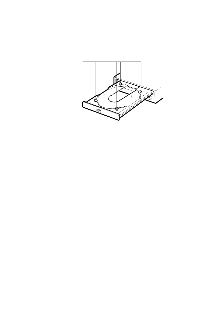
ディ スクトレイ にはロッ クが4 つ付いており 、ドライブを縦に 取り付けたときに
ディ スクが 落ちるのを 防ぎます。
ロック
ご注意
工場出荷時には、4つのロックはロック解除位置(外向き)に設定されていま
す。ロック位置に設定するには、クリック音 が 聞こえるまで 指 でロックを 回し、
ロックを内 向きにしてください 。
22
使いかた
ロックした状態
ロックを解除する
ロックを解除した状態
ロックする

ドライブの右面が下になっているとき
B
C
D
A
DA
C
B
ディ スクを取り扱いやすくするため、ロックB 、 CおよびDをロック位置に設定
し、ロックAはロック解除位置のままにします。
上面
右面
ドライブの左面が下になっているとき
ディ スクを取り扱いやすくするため、ロックA 、CおよびDをロック位置に設定
し、ロックBはロック解除位置のままにします。
上面
左面
使いかた
23

主な仕様
■ 一般仕様
ホストインターフェース ATAPI準拠
ディ スク
使用可能ディスク CD-Digitalオーディオディスク
CD-ROMMode-1データディスク
CD-ROMMode-2form1/form2データ ディスク
CD-ROMXAディスク(読 み 出し 可)
オーディオコンバインドCD-ROMディスク
CD-Iディスク(読み 出し 可 )
CD-IReadyディスク(読 み 出し 可)
CDBridgeディスク
PhotoCDディスク( シ ングルおよび
マルチセッション)
CDEXTRAディスク
ビデオCDディスク、 CDtextディスク
回転速度
2000 min-1(rpm)4–9×CAV
4000 min-1(rpm)8–18×CAV
7000 min-1(rpm)14–32×CAV
■ ドライブ性能
■ 信頼性
主な仕様
24
データ転送速度
サステ インドレー ト 600–1350kバイト(4–9×CAV)
1200–2700kバイト(8–18×CAV)
2100–4800kバイト(14–32×CAV)
バーストレー ト 16.7 Mバイト/s(mode4)
IOCHANNELREADYsupported
16.7 Mバイト/s(MultiwordDMAmode2)
アクセス時間
(ラ ンダムス トローク) 90ms(標準/14–32×CAV)
リードエ ラ ーレート(リトライ含む、標準ディ スク)
L-ECon 1Block/1012ビット
L-ECoff 1Block/109ビット

■ オーディオ
■ 環境条件
■ 寸法と質量
■電源
出力レベル
ライ ン出力 0.75 V(47 kΩ)
ヘッ ドフォン出力 0.55 V(32 kΩ)
動作時
温度 5 ℃〜50 ℃
湿度 10 %〜90 %(結露なし、最高湿球温度:2 9 ℃ )
非動作時
温度 −30 ℃〜50 ℃
湿度 10 %〜90 %(結露なし)
寸法 146×41.4×208 mm(幅/高さ/奥行き)
質量 0.90 kg
電圧 +5 V ± 5 % DCと+12 V ± 10 % DC
電流
トレイの開閉時
+5 VDC;≦1400 mA
+12 VDC;≦1400 mA
シーク、スピンアップ / ダウン時
+ 5VDC;≦1400 mA
+ 12VDC;≦1600 mA
ホール ドトラック 時
+ 5VDC;≦1400 mA
+ 12VDC;≦1200 mA
スタンバイ /スリープ 時
+ 5VDC;≦100 mA
+ 12VDC;≦30 mA
主な仕様
25

■ コネクター
■ レーザー
電源/インターフェース一体 型コネクター
AMP179376-1または同等品
オーディオコネクター Molex5046-04Aまたは同等品
方式 半導体レーザーGaA1As
波長 785 nm
出力 0.3 mW
外観および仕様は、予告なく 変更されるこ とがあり ます。
26
主な仕様

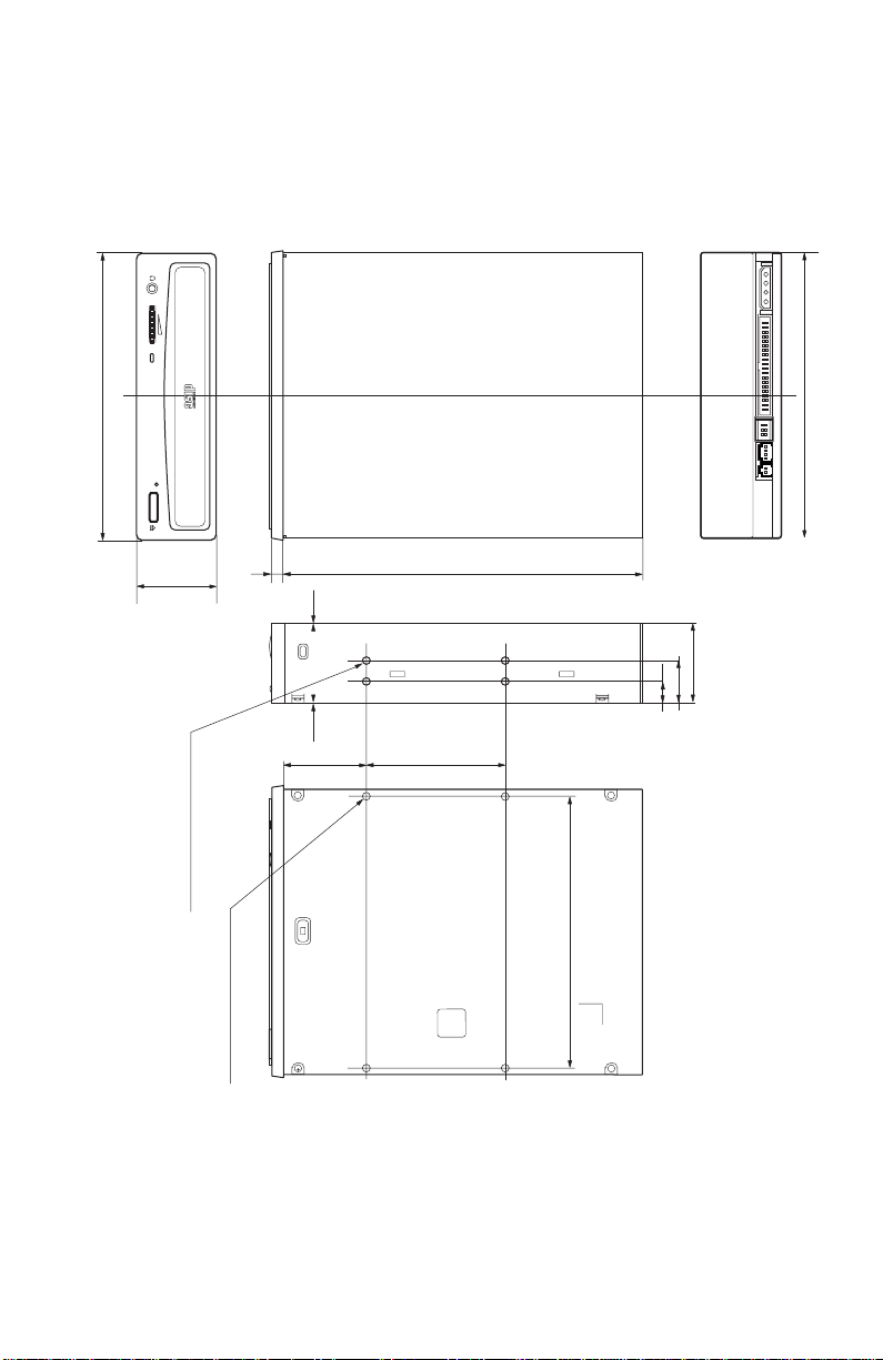
■ 寸法図
重要:
取り付けネジは、側板や底板の表面から6.0mm以上中へ食い込 まないよう
な長さの ものをご使用く ださい。
148
(5
/
8
)
146
(
5
7
(8)
79.25
1
203
41.4
21.9
(
1
11
(
7
/
/
16
8
)
(
)
13
10
/
32
)
/8)
+
(5
139.7
1
/
2
)
42.3
(111/16)
(
(両側に
4-M3
取り付け用ネジ
4
個づつ)
4-M3
5
7
/
)
32
(
0.5
1
/
32
)
(
0.4
1
/
32
)
47.5
(17/8)(3
+
3
/
4
)
取り付け用ネジ
+
単位:mm
主な仕様
27

28

Owner’s Record
The model and serial numbers are located on the top side of the drive. Record these
numbers in the spaces provided below. Refer to them whenever you call upon your sales
representative regarding this product.
Model No. __________________ Serial No. ___________________
WARNING
To prevent fire or shock hazard, do not expose the unit
to rain or moisture.
To avoid electrical shock, do not open the cabinet.
Refer servicing to qualified personnel only.
CAUTION
The use of optical instruments with this product will increase eye hazard.
The use of controls or adjustments or performance of procedures other than those
specified herein may result in hazardous radiation exposure.
This unit uses CD-ROM discs with the following mark.
When you use this unit as an audio CD player, use
compact discs with the following mark.
CAUTION INVISIBLE LASER RADIATION WHEN OPEN. DO NOT
VORSICHT UNSICHTBARE LASERSTRAHLUNG, WENN ABDECKUNG
ADVARSEL USYNLIG LASERSTRÅLING VED ÅBNING SE IKKE IND I
ADVARSEL USYNLIG LASERSTRÅLING NÅR DEKSEL ÅPNES. STIRR
VARNING OSYNLIG LASERSTRÅLNING NÄR DENNA DEL ÄR
V A RO! A VATTAESSA OLET ALTTIINA NÄKYMÄTTÖMÄLLE
STARE INTO BEAM OR VIEW DIRECTLY WITH OPTICAL
INSTRUMENTS.
GEÖFFNET. NICHT IN DEN STRAHL BLICKEN, AUCH
NICHT MIT OPTISCHEN INSTRUMENTEN.
STRÅLEN-HELLER IKKE MED OPTISKE INSTRUMENTER.
IKKE INN I STRÅLEN ELLER SE DIREKTE MED OPTISKE
INSTRUMENTER.
ÖPPNAD. STIRRA EJ IN I STRÅLEN OCH BETRAKTA EJ
STRALEN MED OPTISKA INSTRUMENT.
LASERSÄTEILYLLE. ÄLÄ TUIJOTA SÄTEESEEN ÄLÄKÄ
KATSO SITÄ OPTISEN LAITTEEN LÄPI.
This label is located on
the top of the drive.
Dieser Aufkleber
befindet sich an der
Oberseite des Gehäuses.
29

INFORMATION
You are cautioned that any changes or modifications not expressly approved in this
manual could void your warranty covering this equipment.
Note: This equipment has been tested and found to comply with the limits for a Class B
digital device, pursuant to Part 15 of the FCC Rules. These limits are designed to
provide reasonable protection against harmful interference in a residential installation.
This equipment generates, uses, and can radiate radio frequency energy and, if not
installed and used in accordance with the instructions, may cause harmful interference to
radio communications. However, there is no guarantee that interference will not occur in
a particular installation. If this equipment does cause harmful interference to radio or
television reception, which can be determined by turning the equipment off and on, the
user is encouraged to try to correct the interference by one or more of the following
measures:
– Reorient or relocate the receiving antenna.
– Increase the separation between the equipment and receiver.
– Connect the equipment into an outlet on a circuit different from that to which the
receiver is connected.
– Consult the dealer or an experienced radio/TV technician for help.
CLASS 1
LASER PRODUCT
LASER KLASSE 1
PRODUKT
LUOKAN 1 LASERLAITE
KLASS 1 LASER APPARAT
30
This CD-ROM Drive Unit is classified as a CLASS 1
LASER PRODUCT.
The CLASS 1 LASER PRODUCT label is located
on the top of the drive.
Bei diesem CD-ROM-Laufwerk CDU701 handelt es
sich um ein Laser-Produkt der Klasse 1.
Ein entsprechender Aufkleber mit der Beschriftung
LASER KLASSE 1 PRODUKT befindet sich auf der
Oberseite des Geräts.

Declaration of Conformity
Trade Name: SONY
Model No.: CDU701
Responsible Party: Sony Electronics Inc.
Address: 1 Sony Drive, Park Ridge, NJ. 07656 USA
Telephone No.: 201-930-6970
This device complies with Part 15 of the FCC Rules. Operation is subject to the
following two conditions:
(1) This device may not cause harmful interference, and
(2) This device must accept any interference received, including interference that may
cause undesired operation.
Trademarks
• MS-DOS is a registered trademark of Microsoft Corporation.
• IBM PC, PC/XT, and PC/AT are registered trademarks of International Business
Machines Corporation.
• HP Vectra is a registered trademark of the Hewlett-Packard Company.
• Molex is a registered trademark of Molex, Inc.
• AMP is a registered trademark of AMP, Inc.
31

Contents
Introduction 33
Features............................................................................................ 33
Software Requirement ...................................................................... 34
Example of System Setup ................................................................ 34
Location and Function of Parts and Controls 35
Front Panel ....................................................................................... 35
Rear Panel........................................................................................ 36
Precautions 37
Installing the Drive in Your Computer 38
Preparation ....................................................................................... 38
Setting the Jumpers.......................................................................... 39
Opening the Computer ..................................................................... 40
Preparing a Space for the Drive ....................................................... 41
Mounting the Drive ........................................................................... 42
Connecting the Drive ........................................................................ 43
Mounting the Host Adapter ............................................................... 45
Reassembling the Computer ............................................................ 46
32
Installing the Software Driver 47
How to Install .................................................................................... 47
Operating the Drive 48
Starting the Drive .............................................................................. 48
Ejecting the Disc ............................................................................... 50
How to Use the Disc Locks............................................................... 51
Specifications 53

Introduction
Features
The CDU701 is an internal CD-R OM (Compact Disc Read-Onl y
Memor y) drive unit designed f or use with an IBM PC, HP Vectra, or
compatib le computer . It can read as m uch as 650 Mb ytes of digital
data stored in a single CD-R OM disc.
The CDU701 has the f ollowing f eatures:
General
•5 1/4 inch half-height drive form factor.
• 128-kbyte buffer memory ATAPI compliant (SFF-8020)
• Audio CD like drawer loading of a disc without using a caddy.
• Power loading and power eject of a disc. The disc can also be
ejected manually.
• Housed in an airtight frame casing.
Supported disc formats
• Reads data from CD-ROM, CD-ROM XA, CD-I and CD-I Ready
format discs, and from CD-EXTRA and CD TEXT discs.
• Reads data from CD-BRIDGE format discs including PHOTOCD.
• Reads standard CD-Digital Audio encoded discs.
• Reads Video CD discs.
Performance
• Supports quadruple, 8 times and Max. 32 times speed operations
with real time error correction.
• Fast access time ensuring reliable high-speed data access.
Audio
• Outputs 16-bit digital audio data over the ATA interface.
• Equipped with audio line output and headphones jack for audio
CD playback.
Note:
The CDU701 is not equipped with an ADPCM audio cir cuitr y
required to suppor t CD-R OM XA and CD-I compatib le audio
modes. In addition, the unit does not support the CD-I graphic
decoding function; it has to be pr ovided b y the system.
33Introduction

Software Requirement
To access data on CD-R OM discs, the appr opriate de vice driver and
MSCDEX (supplied with the host adapter) must be installed in your
computer when the OS is MS-DOS/Windo ws 3.1. See the man ual
that comes with the host adapter for details.
The application software y ou need f or using the data on a CD-R OM
disc depends on the type and f ormat of the tar get data. See the
man ual supplied with y our CD-R OM disc f or instructions.
Example of System Setup
To use the CD-R OM drive unit, the f ollo wing components are
required:
• Computer (IBM PC, PC/XT, PC/AT, HP Vectra, or equivalent)
• IDE host adapter (ATA compliant)
• Floppy disk drive
• IDE interface cable (40 ≤ 40 pin flat cable)
• Software (Device driver, Utilities)
The f ollo wing is an e xample of system setup.
Software
34 Introduction
Host computer
Floppy disk
drive
Host adapter
CD-ROM
Drive
A udio cable
Location and Function of Parts and Controls
Front Panel
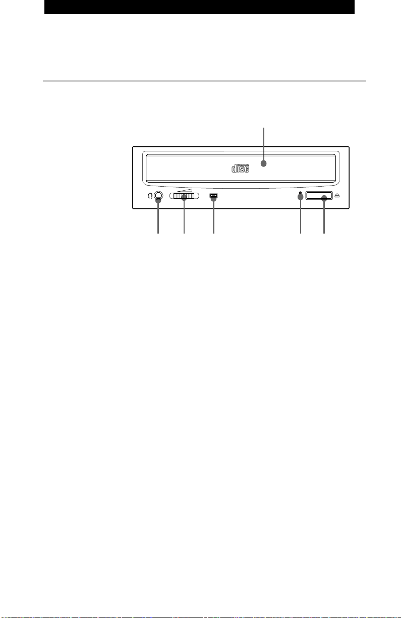
1
34 56
2
11
1Disc drawer
11
Accepts a CD-ROM disc on its tray.
22
2 Headphones jack
22
Accepts a stereo headphones set. Analog audio signals are
output.
33
3 Volume control
33
Controls the volume level of sound output from the headphones
jack 2.
44
4Busy indicator
44
This amber indicator lights or flashes to indicate one of the
following unit conditions.
• Steady lit: TOC (table of contents) read, seek data read,
or audio playback in progress.
• Flashing: Drawer in motion.
55
5 Emergency eject hole
55
Used to open the disc drawer manually when neither the eject
button 6 nor a software command works. Insert a pointed
object, such as a paper clip, into this hole and push.
66
6 Eject button
66
Opens and closes the disc drawer.
35Location and Function of Parts and Controls
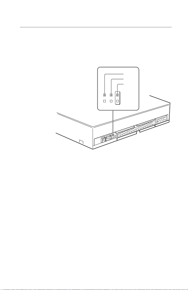
Rear Panel
Pin 1
2
1
11
1Unused
11
22
2ANALOG AUDIO connector
22
Outputs analog audio signals.
33
3 Configuration Jumpers
33
See page 39 for details.
44
4 INTERFACE CONNECTOR (IDE bus)
44
Connect to IDE host adapter using a connecting cable.
55
5 DC INPUT (power-in) connector
55
Connect to the power supply of the host computer.
45
3
36
Location and Function of Parts and Controls

Precautions
■ Installation
• Avoid placing the drive in a location subject to:
– high humidity
– high temperature
– excessive dust
– mechanical vibration
– direct sunlight
• Do not force the power cable. It is keyed to protect the drive.
■ Operation
• Do not move the drive when it is in use. Doing so may cause data
error and damage the optical pick-up.
• Avoid exposing the drive to sudden changes in temperature as
condensation may form on the lens inside the drive. Should the
surrounding temperature suddenly rise while the drive is turned
on, stop using the drive and leave the power on at least one hour
before operating it or turning it off. Operating the drive immediately after a sudden increase in temperature may result in a
malfunction.
■ Transportation
• Close the disc drawer before moving the drive.
• Keep the original packing materials. When you need to ship the
drive to another location, repacking it in its original container will
help you transport it safely.
37Precautions

Installing the Drive in Your Computer
This section pr ovides an e xample of instruction f or installing the
CD-ROM drive unit into y our per sonal computer using the IDE Host
Adaptor (A T A-Compliant).
To connect the CDU701 directl y to the PC’ s IDE por t, consult y our
PC man ufacturer f or instruction.
Preparation
Y ou need the f ollowing par ts and tools (these are not supplied with
the drive):
• A flat-blade screwdriver
• Four screws 3 mm in diameter and 6 mm in length.
• Two mounting rails if your computer has mounting tracks.
Unplug the computer and disconnect the cables attached to the back
to give y our self more r oom to w ork. Do not turn on the po wer of the
computer before completing the entire installation process.
38 Installing the Drive in Your Computer

Setting the Jumpers
Set the jumper s on the rear of the drive in accor dance with the
configuration of y our computer system.
The jumpers are preset at the “MASTER” position as illustrated at
the factor y.
Notes for configuration jumpers:
• Designation of the Drive Number is generally set by inserting a
jumper pin on either the MASTER or the SLAVE pin.
• When the CDU701 is daisy-chained with a Hard Disk Drive on an
IDE Card, set the Hard Disk Drive as MASTER and the CDU701
as SLAVE.
• If the CDU701 is the only device connected to the IDE Card, set
the CDU701 as MASTER.
CSEL
SLAVE
MASTER
However , it should be noted that some per sonal computer s ma y use
CSEL in lieu of the f oresaid MASTER/SLA VE selection. In this
case , remo ve the e xisting jumper s fr om MASTER and SLA VE, and
set a jumper on CSEL. When the CSEL signal of the interface
connector is set lo w, the drive is designated as Drive 0. When the
CSEL is set high, the drive is designated as Drive 1.
Consult y our PC man ufacturer , IDE Car d man ufacturer or dealer f or
further details.
39Installing the Drive Unit into the Computer

Opening the Computer
1 If your computer has its rear side covered by a plastic panel
attached with plastic hook pad, pull it off.
Computer
2 Remove the cover mounting screws.
3 Remove the cover of the computer.
Remove the plastic panel.
Rear plastic panel
Cover mounting screw
Remove the screws.
Installing the Drive Unit into the Computer
40
Remove the computer cover.

Preparing a Space for the Drive
1 Remove the screws and brackets securing the floppy disk drive
and the lower drive bay blanking plate.
Remove the screws
and brackets.
2 Disconnect the floppy disk drive.
Floppy disk drive
Lower dirve bay
blanking plate
Floppy disk drive
3 Remove the floppy disk drive and the blanking plate.
Installing the Drive Unit into the Computer
Floppy disk drive
Blanking plate
41

Mounting the Drive
If mounting rails are necessar y, attac h them to the drive in the same
way as y our flopp y disk drive and slide the drive into the lo wer drive
ba y. If mounting rails are not required in y our system, scre w the
drive in place .
Slide the drive into the lower bay.
Installing the Drive Unit into the Computer
42

Connecting the Drive
Connect the drive to the computer with the f ollo wing connector s:
• DC INPUT connector
• AUDIO OUT connector (if you plan to connect audio equipment)
• INTERFACE CONNECTOR.
INTERFACE CONNECTOR
■ DC INPUT connector
The pin assignment is as f ollo ws.
After matc hing the be veled edg es, inser t the plug of the po wer
suppl y cab le to the DC INPUT connector and push it firml y in place .
Caution: Impr oper connection ma y dama ge the drive and v oid the
warranty .
AUDIO OUT
connector
+5 V DC +12 V DC
DC INPUT connector
DC INPUT connector
GND
P ower supply cable
(4-pin connection cable)
Installing the Drive Unit into the Computer
43

■ AUDIO OUT connector
The pin assignment is as f ollo ws:
■ INTERFACE CONNECTOR
1 Firmly insert one end of the interface cable into the INTER-
FACE CONNECTOR.
pin Audio Signal
1 R signal
2 ground
3 ground
4 L signal
Pin 1
INTERFACE
CONNECTOR
INTERFACE cable
2 Attach the other end of the cable to the host adapter.
Host adapter
44 Installing the Drive Unit into the Computer
INTERFACE cable

Mounting the Host Adapter
Install the host adapter in one of the a vailab le system e xpansion slots
of y our computer . Refer to the operating instructions inc luded with
the host adapter for complete instructions on installation and
settings.
Install the host adapter in
one of the expansion slots.
45Installing the Drive Unit into the Computer

Reassembling the Computer
1 Reinstall the floppy disk drive in the top drive bay.
Reinstall the floppy disk drive.
2 Reconnect the interface cables to the floppy disk drive.
3 Fasten the screws and front brackets as they were before.
4 Tuck the cables behind the drives so that they do not protrude
above the power supply module.
Tuck the cables.
Power supply
5 After checking the following points, slide the computer’s cover
on and fasten the cover mounting screws at the back of the
computer.
• Are the connections between the drive and computer correct?
• Are the jumpers set to the appropriate positions?
6 Remount the rear plastic panel and refer back to the proper
installation section if you answered “no” to either of the
questions above.
Installing the Drive Unit into the Computer
46

Installing the Software Driver
The installation diskette enc losed in the pac kage contains tw o
software items:
• Installer
• Device driver for MS-DOS/Windows 3.1
Note:
Both Micr osoft CD-R OM Extensions (MSCDEX) or equiv alent and
Son y’s De vice Driver are required to run the CDU701 under the
MS-DOS and Windo ws 3.1 en vironment.
Theref ore , prior to loading the installation diskette , make sure that
the MSCDEX is in the DOS director y of y our har d disk drive
(C:\DOS). Although MSCDEX is inc luded in the most up-to-date
MS-DOS (ver . 6.2), you ma y need to obtain the software fr om y our
PC dealer if y ou do not ha ve it.
The installer will automatically load MSCDEX via the
AUT OEXEC.B AT file and installs the De vice Driver via the
CONFIG.SYS file , if MSCDEX is alread y in Drive C:\DOS.
How to Install
At the DOS Pr ompt A: (Drive A active),
>A:\
Load the diskette into the flopp y disk Drive A, and type “install”.
>A:\install
and then, press the Enter ke y.
After installation, the f ollo wing lines are ad ded to CONFIG.SYS
and A UTOEXEC.B A T files.
in CONFIG.SYS:
Device=C:\DEV\ATAPI_CD.SYS /D:mscd000 /I:0
i n AUTOEXEC.B A T :
C:\DOS\MSCDEX.EXE /D:mscd000 /M:12 /V
Installing the Software Driver
47

Operating the Drive
This section describes ho w to star t the drive and eject a disc.
Starting the Drive
1 Turn on the power of your computer.
2 Press the eject button.
The drawer comes out automatically.
Press the eject button.
3 Place a disc in the drawer with its label side up.
Operating the Drive
48
Place a disc with
its label side up.
Note:
When the drive is set up in ver tical position, use the disc loc ks to
pre vent y our disc fr om falling. See “Ho w to Use the Disc Loc ks” on
page 51 for details.
Disc locks
4 Gently push the drawer or press the eject button to close the
drawer.
The drive may begin reading the Table of Contents (TOC) data
when it accepts the disc. The busy indicator lights up in amber
while the drive is reading the TOC.
For subsequent drive operations, follow the instructions provided
with the application software you are using.
Note:
The b usy indicator sta ys lit in amber if:
– the disc is not properly placed on the loading tray
– a malfunction occurs.
In either case , eject the disc and place it in the loading tra y again
making sure that it sits pr operl y in the tra y. If doing this does not
solve the pr ob lem and the b usy indicator still remains lit in amber ,
consult y our dealer or qualified ser vice per sonnel.
Caution: Do not f or cib ly c lose the disc dra wer. Appl ying e xcessive
force ma y dama g e the loading mec hanism. The tra y’s mec hanism is
designed to operate with a “feather touch”.
Operating the Drive
49
Ejecting the Disc
To eject the disc, press the eject b utton on the fr ont panel. The
dra wer comes out automaticall y .
Press the eject button.
Note:
The eject b utton does not w ork if it is disab led b y:
– the software you are using
■ Opening the drawer manually in an emergency
Y ou can open the dra wer man uall y when it fails to come out b y
means of the eject b utton or software commands. T o do this, follo w
the pr ocedure belo w:
1 Turn off the power of your computer.
2 Insert a pointed object, such as a paper clip, into the emergency
eject hole and push.
Operating the Drive
50
Approx. 40 mm
After remo ving a disc fr om the drive unit, consult y our dealer or
qualified ser vice per sonnel.

How to Use the Disc Locks
The disc tra y has f our disc loc ks that pre vent the disc fr om falling
when the drive is set up in ver tical position.
Note:
When the drive is used in horizontal position, you do not need to
lock the disc.
■ Locking and unlocking
All of the f our loc ks are set in the unloc ked position (facing
outwar d) when the drive is shipped fr om the factor y. To set the loc k
in the loc ked position, turn it with y our fing er s until y ou hear a c lick
so that it faces inwar d.
Disc locks
locked unlocked
to lockto unlock
Operating the Drive
51
When the drive’s right side is down
B
C
D
A
DA
C
B
To facilitate disc handling, set the disc loc ks B, C and D into the
loc ked position, and lea ve the disc loc k A in the unloc ked position.
Top side
Right side
When the drive’s left side is down
To facilitate disc handling, set the disc loc ks A, C and D into the
loc ked position, and lea ve the disc loc k B in the unloc ked position.
Operating the Drive
52
Top side
Left side

Specifications
■ General
Host interface AT API compliant
Disc
Acceptable discs CD-Digital A udio discs
Rotational speed
■ Drive performance
Data transfer rate
Sustained rate 600–1350 kb ytes (4–9 × CAV)
Burst rate 16.7 Mbytes/s (mode 4)
CD-ROM mode-1 data discs
CD-ROM mode-2 f orm1/f orm2 data discs
CD-ROM XA discs (readab le)
Audio-combined CD-R OM discs
CD-I discs (readable)
CD-I Ready discs (readable)
CD Bridge discs
Photo CD discs (single and multi session)
CD EXTRA discs
Video CD discs, CD TEXT discs
2000 min
-1
(rpm)
4–9 × CAV
4000 min
-1
(rpm)
8–18 × CAV
7000 min
-1
(rpm)
14–32 × CAV
1200–2700 kb ytes (8–18 × CAV)
2100–4800 kb ytes (14–32 × CAV)
IO CHANNEL READ Y suppor ted
16.7 Mb ytes/s (Multiw ord DMA mode 2)
■ Reliability
■ Audio
Access time
(Random str oke) 90 ms (typical/14–32 × CAV)
Read err or rate (inc ludes retr y, with a standar d disc)
L-EC on 1 block /10
L-EC off 1 block /10
l2
9
bits
bits
Output le vel
Line out 0.75 V at 47 k Ω
Headphone 0.55 V at 32 Ω
Specifications
53

■ Environmental conditions
Operating
Temperature 5 °C to 50 °C (41 °F to 122 °F)
Humidity 10 % to 90 % (Max wet b ulb 29 °C)
Atmosphere Non-condensing
Non-operating/Storage
Temperature –30 °C to 50 °C (–22 °F to 122 °F)
Humidity 10 % to 90 %
Atmosphere Non-condensing
■ Dimensions and mass
Dimensions 146 × 41.4 × 208 mm (w/h/d)
Mass 0.90kg (2 lb)
■ Power requirement
V olta ge +5 V ± 5 % DC and +12 V ± 10 % DC
Current Tray Open/Close
3
(5
/4× 1 11/16 × 8 1/4 inches)
+5 V DC ; ≤1400 mA
+12 V DC ; ≤1400 mA
Seeking and Spin Up/Do wn
+5 V DC ; ≤1400 mA
+12 V DC ; ≤1600 mA
Hold Trac k State
+5 V DC ; ≤1400 mA
+12 V DC ; ≤1200 mA
Standby/Sleep
+5 V DC ; ≤100 mA
+12 V DC ; ≤30 mA
■ Connectors
■ Laser
Specifications
54
INTERFACE CONNECT OR
(with DC INPUT connector) AMP 179376-1 or equiv alent
AUDIO OUT connector Molex 5046-04A or equiv alent
T ype Semiconductor laser GaAlAs
Wave length 785 nm
Output po wer 0.3 mW
Design and specifications are subject to c hang e without notice .
■ Dimension diagram
Important:
The o verhang of the scre ws should not e xceed 6.0 mm fr om the
surface of the side panels or the bottom plate .
148 (5
7
/
8
)
(8)
42.3
(111/16)
(4-on each side)
4-M3 Mounting screws
4-M3 Mounting screws
5
7
(
/
)
32
(
0.5
1
/
32
)
(
0.4
1
/
32
)
47.5
(17/8)(3
+
203
79.25
1
/
)
8
41.4
21.9
(1
11
(
7
/
/
16
8
)
(
)
13
10
/
32
)
+
(5
139.7
1
/
2
)
146
(5
/
4
)
3
+
Unit mm(inch)
Specifications
55

56

CAUTION INVISIBLE LASER RADIATION WHEN OPEN. DO NO T
VORSICHT UNSICHTBARE LASERSTRAHLUNG, WENN ABDECKUNG
ADVARSEL USYNLIG LASERSTRÅLING VED ÅBNING SE IKKE IND I
ADVARSEL USYNLIG LASERSTRÅLING NÅR DEKSEL ÅPNES. STIRR
VARNING OSYNLIG LASERSTRÅLNING NÄR DENNA DEL ÄR
V A RO! A VATTAESSA OLET ALTTIINA NÄKYMÄTTÖMÄLLE
STARE INTO BEAM OR VIEW DIRECTLY WITH OPTICAL
INSTRUMENTS.
GEÖFFNET. NICHT IN DEN STRAHL BLICKEN, AUCH
NICHT MIT OPTISCHEN INSTRUMENTEN.
STRÅLEN-HELLER IKKE MED OPTISKE INSTRUMENTER.
IKKE INN I STRÅLEN ELLER SE DIREKTE MED OPTISKE
INSTRUMENTER.
ÖPPNAD. STIRRA EJ IN I STRÅLEN OCH BETRAKTA EJ
STRALEN MED OPTISKA INSTRUMENT.
LASERSÄTEILYLLE. ÄLÄ TUIJOTA SÄTEESEEN ÄLÄKÄ
KATSO SITÄ OPTISEN LAITTEEN LÄPI.
PRODUITS LASER DE CLASSE 1
Cette étiquette se trouve
sur la partie supérieure
du lecteur.
Marques déposées
• MS-DOS est une marque déposée de Microsoft Corporation.
• IBM PC, PC/XT et PC/AT sont des marques déposées de International Business
Machines Corporation.
• HP Vectra est une marque déposée de la société Hewlett-Packard.
• Molex est une marque déposée de Molex, Inc.
• AMP est une marque déposée de AMP, Inc.
57

Sommaire
Intr oduction 5 9
Fonctions .......................................................................................... 59
Exigences logicielles ........................................................................ 60
Exemple d’installation de système.................................................... 60
Emplacement et fonction des composants et des commandes
Panneau avant .................................................................................. 61
Panneau arrière................................................................................ 62
61
Précautions 63
Installation du lecteur dans votre ordinateur 6 4
Préparation ....................................................................................... 64
Configuration des cavaliers .............................................................. 65
Ouverture de l’ordinateur .................................................................. 66
Préparation d’un emplacement pour le lecteur................................. 67
Montage du lecteur ........................................................................... 68
Connexion du lecteur........................................................................ 69
Installation de l’adaptateur hôte........................................................ 71
Réassemblage de l’ordinateur .......................................................... 72
Installation du pilote de logiciel 73
Procédure d’installation .................................................................... 73
Fonctionnement du lecteur 74
Démarrage du lecteur....................................................................... 74
Ejection du disque ............................................................................ 76
Utilisation des verrous de disque...................................................... 77
58
Caractéristiques 79

Introduction
Fonctions
Le CDU701 est un lecteur interne de CD-R OM (disque compact
Read-Only Memory) conçu pour être utilisé sur un PC IBM, sur HP
V ectra ou sur un or dinateur compatib le . Il peut lire jusqu’à 650 Mo
de données n umériques stoc kées sur un seul CD-R OM.
Le CDU701 est doté des f onctions suiv antes:
Généralités
• Format de lecteur de disque 5,25 pouces.
• 128 Ko de mémoire tampon compatible ATAPI (SFF-8020)
• Chargement du disque par un tiroir similaire à celui d’un CD
audio, sans caddy.
• Chargement et éjection automatique du disque. Vous pouvez
également l’extraire manuellement.
• Le tout est protégé par un boîtier étanche.
Formats de disques pris en charge
• Lit des données de CD-ROM, CD-ROM XA, CD-I et CD-I Ready
et de CD-EXTRA et CD TEXT.
• Lit des données de disques de format CD-BRIDGE, y compris CD
PHOTO.
• Lit les disques standard codés CD-Digital-Audio.
• Lit les disques CD vidéo.
Performances
• Gère des opérations à une vitesse multipliée par 4, 8 et 32
maximum avec une correction d’erreur en temps réel.
• Temps d’accès rapide permettant un accès à grande vitesse fiable
aux données.
Audio
• Sortie de données audio numériques 16 octets via une interface
ATA.
• Sortie ligne audio et prise de casque Jack permettant d’écouter des
CD audio.
Remarque:
Le CDU701 ne dispose pas de cir cuits audio MICD A nécessaires
pour gérer les modes audio compatib les CD-R OM XA et CD-I. En
outre, l’unité ne gère pas la fonction de décodage graphique CD-I ;
le système doit la f ournir .
59Introduction

Exigences logicielles
Pour pouv oir accéder aux données sur les CD-R OM, vous de vez
avoir installé un pilote de périphérique et MSCDEX (f ourni a vec
l’adaptateur hôte) sur v otre or dinateur si v otre SE est MS/DOS/
Windo ws 3.1. Pour de plus amples détails, repor tez-v ous au man uel
fourni a vec l’adaptateur hôte .
Le logiciel d’application requis pour e xploiter les données d’un CDROM dépend du type et du f ormat des données cib les. V ous
trouverez les instructions dans le man uel f ourni a vec le CD-R OM.
Exemple d’installation de système
Exemple d’installation de système
Pour utiliser le lecteur de CD-R OM, vous a vez besoin des
composants suiv ants:
• Ordinateur (PC IBM, PC/XT, PC/AT, HP Vectra, ou équivalent)
• Connecteur hôte IDE (compatible ATA)
• Lecteur de disquettes
• Câble d’interface IDE (ruban en broche 40 ≤ 40)
• Logiciels (pilote de périphérique, utilitaires)
Exemple d’installation de système .
Logiciel
60 Introduction
Lecteur de
disquettes
Lecteur de
CD-ROM
Câble audio
Ordinateur hôte
Connecteur
hôte

Emplacement et fonction des composants
et des commandes
Panneau avant
1
34 56
2
11
1Tiroir du disque
11
Emplacement du CD-ROM.
22
2 Prise casque jack
22
Branchement du casque stéréo. Sortie des signaux audio
analogiques.
33
3 Réglage du volume
33
Contrôle du volume du son sortant par la prise casque jack 2.
44
4 Témoin de fonctionnement
44
Ce témoin orange s’allume ou clignote pour indiquer un des états
suivants de l’unité.
• Témoin fixe : Table des matières lue, recherche des données ou
lecture audio en cours.
• Clignotant : Lecteur en cours d’opération.
55
5 Trou d’ouverture d’urgence
55
Permet d’ouvrir manuellement le tiroir du lecteur lorsque ni le
bouton d’ouverture et de fermeture ni la commande du logiciel
ne fonctionnent. Entrez un objet pointu, un trombone par
exemple, dans le trou et appuyez.
66
6 Bouton d’ouverture et de fermeture
66
Permet d’ouvrir et de fermer le tiroir du lecteur.
61Emplacement et fonction des composants et des commandes

Panneau arrière
Broche 1
2
1
11
1Inutilisée
11
22
2Connecteur AUDIO ANALOGIQUE
22
Sortie des signaux audio analogiques.
33
3 Cavaliers de configuration
33
Consulter la page 65 pour de plus amples détails.
44
4 CONNECTEUR D’INTERFACE (bus IDE)
44
Connexion à l’adaptateur hôte IDE à l’aide d’un câble de
connexion.
55
5 Connecteur DC INPUT (arrivée alimentation)
55
Connexion à l’alimentation électrique de l’ordinateur hôte.
45
3
62
Emplacement et fonction des composants et des commandes

Précautions
■ Installation
• Evitez de placer le lecteur dans un site exposé à:
– une forte humidité
– des températures élevées
– une poussière excessive
– des vibrations mécaniques
– la lumière directe du soleil
• Ne tirez pas violemment sur le câble électrique. Il est bloqué pour
protéger le lecteur.
■ Fonctionnement
• Ne déplacez pas le lecteur lorsqu’il est en utilisation. Vous
pourriez causer des erreurs de données et endommager la tête de
lecture optique.
• Evitez d’exposer le lecteur à des changements de températures
soudains, car cela pourrait produire de la condensation sur la
lentille du lecteur. Si la température ambiante venait à augmenter
soudainement lors de l’utilisation du lecteur, arrêtez l’utilisation
du lecteur et laissez-le allumé pendant au moins une heure avant
de l’utiliser à nouveau ou de l’éteindre. L’utilisation du lecteur
immédiatement après une augmentation soudaine de la
température pourrait entraîner un dysfonctionnement.
■ Transport
• Fermez le tiroir du disque avant de déplacer le lecteur.
• Conservez l’emballage d’origine afin de le réutiliser pour transporter le lecteur de façon sûre.
63Précautions

Installation du lecteur dans votre ordinateur
Cette rubrique v ous donne un e xemple d’instruction pour installer le
lecteur de CD-R OM dans v otre or dinateur per sonnel en utilisant
l’adaptateur hôte IDE (compatib le ATA).
Pour connecter le CDU701 directement au port IDE du PC,
consultez le fabricant de v otre or dinateur pour obtenir des instructions.
Préparation
V ous a vez besoin des pièces et outils suiv ants (ils ne sont pas f ournis
avec le lecteur):
• Un tournevis plat
• Quatre vis de 3 mm de diamètre et de 6 mm de long.
• Deux rails de montage si votre ordinateur a des pistes de montage.
Mettez v otre or dinateur hor s tension et déconnectez les câb les
branc hés à l’arrière pour a voir plus de place pour tra vailler . Ne
remettez pas l’or dinateur sous tension a vant d’a voir entièrement
terminé le processus d’installation.
64 Installation du lecteur dans votre ordinateur

Configuration des cavaliers
Réglez les ca valier s à l’arrière du lecteur selon la configuration de
votre système d’or dinateur .
Les ca valier s sont préconfigurés sur la position “MASTER ” selon
le réglage usine.
Remarques sur les cavaliers de configuration:
• En général, pour désigner le numéro de lecteur, il suffit d’insérer
une broche cavalier sur la broche MASTER ou la broche SLAVE.
• Lorsque le CDU701 est connecté à un disque dur avec une carte
IDE (connexion en série), réglez le lecteur de disque dur sur
MASTER et le CDU701 sur SLAVE.
• Si le CDU701 est le seul périphérique connecté à la carte IDE,
réglez le CDU701 sur MASTER.
CSEL
SLAVE
MASTER
Cependant, certains ordinateurs utilisent CSEL au lieu de la
sélection MASTER/SLA VE décrite ci-dessus. Dans ce cas, ôtez les
ca valier s e xistants de MASTER et SLA VE et placez-en un sur
CSEL. Lor sque le signal CSEL du connecteur de l’interface est en
bas, le lecteur est désigné comme Lecteur 0. Lorsque le CSEL est en
haut, le lecteur est désigné comme Lecteur 1.
Contactez le fabricant de v otre PC, de v otre car te IDE ou v otre
revendeur pour obtenir de plus amples renseignements.
65Installation du lecteur dans votre ordinateur

Ouverture de l’ordinateur
1 Si l’arrière de votre ordinateur est couvert par un panneau en
plastique tenu par des clips en plastique, enlevez-le.
Ordinateur
2 Enlevez les vis du boîtier.
3 Enlevez le boîtier de l’ordinateur.
Enlevez le panneau en
plastique
Panneau arrière en plastique
Vis du boîtier
Enlevez les vis
Installation du lecteur dans votre ordinateur
66
Enlevez le boîtier.

Préparation d’un emplacement pour le lecteur
1 Enlevez les vis et les broches du lecteur de disquettes et le cache
inférieur de la baie du lecteur.
Lecteur de disquettes
Cache inférieur de la
Enlevez les vis et les
broches
2 Déconnectez le lecteur de disquettes.
Lecteur de disquettes
baie du lecteur
3 Enlevez le lecteur de disquettes et le cache.
Installation du lecteur dans votre ordinateur
Lecteur de disquettes
Cache
67

Montage du lecteur
Si des rails de montage sont nécessaires, rattachez-les au lecteur de
la même façon que v otre lecteur de disquettes et insérez le lecteur
dans la baie du lecteur inférieure . Si votre système ne requier t pas de
rails de monta ge, vissez le lecteur .
Insérez le lecteur dans la baie inférieure.
Installation du lecteur dans votre ordinateur
68
Connexion du lecteur
Connectez le lecteur à l’or dinateur a vec les connecteur s suiv ants :
• Connecteur DC INPUT
• Connecteur AUDIO OUT (si vous désirez connecter un
équipement audio)
• CONNECTEUR D’INTERFACE.
■ Connecteur DC INPUT
L ’affectation des br oc hes est la suiv ante:
+5 V DC +12 V DC
CONNECTEUR D’INTERFACE
Connecteur DC
INPUT
Connecteur
AUDIO OUT
GND
Après a voir connecté les e xtrémités en biais, insérez la prise du
câble d’alimentation dans le connecteur DC INPUT et mettez-les
fermement en place.
Attention: une mauv aise conne xion peut endomma ger le lecteur et
ann uler la garantie .
Connecteur DC INPUT
Câble d’alimentation
(câble de connexion à 4 broches)
Installation du lecteur dans votre ordinateur
69
■ Connecteur AUDIO OUT
L ’affectation des br oc hes est la suiv ante:
■ CONNECTEUR D’INTERFACE
1 Insérez fermement une extrémité du câble d’interface dans le
CONNECTEUR D’INTERFACE.
CONNECTEUR
D’INTERF ACE
Broche Signal A UDIO
1 Signal R
2 Terre
3 Terre
4 Signal L
broche 1
Câble d’INTERFACE
2 Rattachez l’autre extrémité du câble à l’adaptateur hôte.
Connecteur hôte
70 Installation du lecteur dans votre ordinateur
Câble
d’INTERFACE
Installation de l’adaptateur hôte
Installez l’adaptateur hôte dans un des emplacements d’e xpansion
disponib les du système sur v otre or dinateur . Repor tez-v ous au
man uel d’instructions f ourni a vec l’adaptateur hôte pour obtenir
toutes les instructions concernant l’installation et les paramètres.
Installez l’adaptateur hôte dans un
des emplacements d’expansion.
71Installation du lecteur dans votre ordinateur
Réassemblage de l’ordinateur
1 Réinstallez le lecteur de disquettes dans la baie de lecteur
supérieure.
Réinstallez le lecteur de disquettes.
2 Rebranchez les câbles d’interface au lecteur de disquettes.
3 Fixez les vis et les broches avant comme elles étaient
auparavant.
4 Placez les câbles derrière les lecteurs de telle façon qu’ils ne
dépassent pas au-dessus du module d’alimentation électrique.
Placez les câbles
5 Après avoir vérifié les points suivants, remettez le boîtier de
l’ordinateur en place et serrez les vis du boîtier se trouvant à
l’arrière de l’ordinateur.
• Les connexions entre le lecteur et l’ordinateur sont-elles
correctes?
• Les cavaliers se trouvent-ils dans la bonne position ?
6 Remontez le panneau arrière en plastique et reportez-vous à la
rubrique d’installation correspondante si vous avez répondu
“Non ” aux questions posées ci-dessus.
Installation du lecteur dans votre ordinateur
72
Alimentation
électrique

Installation du pilote de logiciel
La disquette d’installation fournie contient deux éléments logiciels:
• le logiciel d’installation
• le pilote de périphérique pour MS-DOS/Windows 3.1.
Remarque:
Les e xtensions pour CD-R OM Microsoft (MSCDEX)ou équiv alent
et le pilote de périphérique Son y sont tous deux nécessaires au
fonctionnement du CDU701 dans un en vir onnement MS-DOS et
Windo ws 3.1.
Par conséquent, a vant de c har ger la disquette d’installation, assurezvous que MSCDEX se tr ouve dans le réper toire DOS de v otre
disque dur (C:\DOS). Bien que MSCDEX soit inc lus dans la ver sion
la plus récente de MS-DOS (ver sion 6.2), vous de vrez peut-être
acquérir ce logiciel auprès de v otre re vendeur inf ormatique si v ous
ne l’a vez pas.
Le pr ogramme d’installation c har g era automatiquement MSCDEX
par le biais du fic hier A UTOEXEC.B A T et installera le pilote de
périphérique grâce au fic hier CONFIG.SYS, si MSCDEX se tr ouve
déjà sur le lecteur C:\DOS.
Procédure d’installation
Lors de l’in vite DOS A: (lecteur A actif),
>A:\
Insérez la disquette dans le lecteur A, et saisissez “install”.
>A:\install
Appuyez ensuite sur la touche Entrée.
Après l’installation, les lignes suiv antes sont ajoutées aux fic hier s
CONFIG.SYS et A UTOEXEC.B AT .
Dans CONFIG.SYS:
Device=C:\DEV\ATAPI_CD.SYS /D:mscd000 /I:0
Dans A UTOEXEC.B AT :
C:\DOS\MSCDEX.EXE /D:mscd000 /M:12 /V
Installation du pilote de logiciel
73

Fonctionnement du lecteur
Cette rubrique décrit comment démarrer le lecteur et éjecter un
disque.
Démarrage du lecteur
1 Mettez votre ordinateur sous tension.
2 Appuyez sur le bouton d’ouverture et de fermeture.
Le tiroir sort automatiquement.
Appuyez sur le bouton
d’ouverture et de fermeture.
Fonctionnement du lecteur
74
3 Placez un disque dans le tiroir la face imprimée sur le dessus.
Placez un disque avec la face
imprimée sur le dessus.

Remarque:
Si le lecteur est installé en position ver ticale , utilisez les verr ous de
disque pour éviter que le disque tombe. Pour plus de détails,
repor tez-v ous à la section “ Utilisation des verr ous de disque ” de la
page 77.
Verrous
de disque
4 Poussez doucement le tiroir ou appuyez sur le bouton
d’ouverture et de fermeture pour le refermer.
Le lecteur commencera à lire les données de la table des matières
après l’insertion du disque. Le témoin de fonctionnement affiche
une lumière orange lorsque le lecteur lit la table des matières.
Suivez les instructions fournies avec le logiciel que vous utilisez
pour prendre connaissance de toutes les autres opérations du
lecteur.
Remarque:
Le témoin orange de fonctionnement reste allumé:
– le disque n’est pas correctement placé dans le tiroir;
– il y a un dysfonctionnement.
Dans les deux cas, sor tez le disque et placez-le à nouveau dans le
tiroir en v ous assurant qu’il est correctement installé. Si les
problèmes persistent et si le témoin orange de fonctionnement reste
toujour s allumé, consultez v otre re vendeur ou une per sonne qualifiée
du service clientèle.
Attention: ne f or cez pas la f ermeture du tir oir. En appuy ant tr op
fort, vous risquez d’endomma ger le mécanisme de c har g ement. Le
mécanisme du tiroir est conçu pour fonctionner dès la plus petite
pression.
Fonctionnement du lecteur
75

Ejection du disque
Pour sor tir le disque , appuy ez sur le bouton d’ouver ture et de
fermeture du panneau a vant. Le tir oir sor t automatiquement.
Appuyez sur le bouton
d’ouverture et de fermeture.
Remarque:
Le bouton d’ouver ture et de f ermeture ne f onctionne pas s’il est
désactivé par:
– le logiciel que vous utilisez
■ Ouverture manuelle du tiroir en cas d’urgence
V ous pouvez ouvrir le tir oir man uellement si v ous n’y par venez pas
en appuy ant sur le bouton d’ouver ture et de f ermeture ou en utilisant
les commandes du logiciel. Pour ce faire , suivez les instructions cidessous:
1 Eteignez votre ordinateur.
Fonctionnement du lecteur
76
2 Entrez un objet pointu, comme un trombone, dans le trou
d’ouverture d’urgence et appuyez.
Environ 40 mm
Après a voir ôté le disque de l’unité du lecteur , consultez v otre
revendeur ou la per sonne qualifiée du ser vice c lientèle .

Utilisation des verrous de disque
Le dispositif de c har gement de disques est doté de quatre verr ous
pour empêcher le disque de tomber lorsque le lecteur est installé en
position ver ticale .
Verrous de disque
Remarque:
Si le lecteur est installé dans une position horizontale , vous n’aurez
pas besoin d’utiliser les verr ous de disque .
■ Verrouillage et déverrouillage
Les quatre verr ous sont en position déverr ouillée (ver s l’e xtérieur)
en configuration usine . Pour mettre les verr ous en position
verr ouillée , tournez-les a vec v os doigts jusqu’à ce que v ous
entendiez un c lic lor squ’ils sont tournés ver s l’intérieur .
Verrouillé déverrouillé
verrouillerdéverrouiller
Fonctionnement du lecteur
77

Lorsque le côté droit du lecteur est en bas
B
C
D
A
DA
C
B
Pour faciliter le maniement du disque , mettez les verr ous de disque
B, C et D dans la position verr ouillée et laissez le verr ou A dans la
position non verr ouillée .
Dessus
Côté gauche
Lorsque le côté gauche du lecteur est en bas
Pour faciliter le maniement du disque , mettez les verr ous de disque
A, C et D dans la position verr ouillée et laissez le verr ou B dans la
position non verr ouillée .
Fonctionnement du lecteur
78
Dessus
Côté gauche

Caractéristiques
■ Généralités
Interface d’hôte CD compatib le AT API
Disc
Disques admis CD-Digital A udio
Vitesse de r otation
■ Performances du lecteur
Disques de données CD-R OM mode-1
Disques de données CD-R OM mode-2
form1/form2
CD-ROM XA (en lecture)
CD-ROM audio combinés
CD-I (en lecture)
CD-I Ready (en lecture)
CD Bridge
Photo CD (session unique et multi-
session)
CD EXTRA
CD Vidéo, CD TEXT
2000 min
-1
(rpm)
4–9 × CAV
4000 min
-1
(rpm)
8–18 × CAV
7000 min
-1
(rpm)
14–32 × CAV
■ Fiabilité
■ Audio
T aux de transf er t des données
T aux contin u 600–1350 K o (4–9 × CAV)
1200–2700 K o (8–18 × CAV)
2100–4800 K o (14–32 × CAV)
T aux en salves 16.7 Mo/s (mode 4)
IO CHANNEL READ Y géré
16.7 Mo/s (Multiw ord DMA mode 2)
Temps d’accès
(Frappe aléatoire) 90 ms (typique/14–32 × CAV)
T aux d’erreur (nouvel essai a vec un disque standar d inc lus)
L-EC allumé 1 block /10
L-EC éteint 1 block /10
l2
9
bit
bit
Niveau de sor tie
Sortie ligne 0.75 V à 47 k Ω
Casque 0.55 V à 32 Ω
Caractéristiques
79

■ Conditions d’utilisation
En fonctionnement
Température 5 °C à 50 °C (41 °F à 122 °F)
Humidité 10 % à 90 %
Atmosphère Sans condensation
A l’arrêt/stockage
Température –30 °C à 50 °C (–22 °F à 122 °F)
Humidité 10 % à 90 %
Atmosphère Sans condensation
■ Dimensions et poids
Dimensions 146 × 41.4 × 208 mm (l/h/p)
Poids 0,90 kg (2 lb)
■ Alimentation électrique
Tension +5 V ± 5 % CC et +12 V ± 10 % CC
En fonction Ouver ture/f ermeture du tir oir
(température au thermomètre mouillé
max. 29 °C)
3
(5
/4× 1 11/16 × 8 1/4 pouces)
+5 V CC ; ≤1400 mA
+12 V CC ; ≤1400 mA
Recherche et mise en rotation/arrêt de la
rotation
+5 V CC ; ≤1400 mA
+12 V CC ; ≤1600 mA
Pause sur piste
+5 V CC ; ≤1400 mA
+12 V CC ; ≤1200 mA
Veille
+5 V CC ; ≤100 mA
+12 V CC ; ≤30 mA
■ Connecteurs
■ Laser
Caractéristiques
80
CONNECTEUR D’INTERF ACE
(avec connecteur DC INPUT)
AMP 179376-1 ou équiv alent
Connecteur A UDIO OUT Mole x 5046-04A ou équiv alent
T ype Laser semi-conducteur GaAlAs
Longueur d’ondes 785 nm
Tension de sor tie 0.3 mW
Les spécifications et les caractéristiques sont sous réser ve de
modifications.

■ Diagramme des dimensions
N. B.:
Les vis ne doivent pas dépasser de 6,0 mm de la surface de la façade
du côté ou du fond.
148 (5
7
/
8
)
(8)
42.3
(111/16)
5
7
(
/
)
32
4 vis de 3 mm de diamètre
(toutes sur le même côté)
4 vis de 3 mm de diamètre
(
0.5
1
/
32
)
(
0.4
1
/
32
)
47.5
(17/8)(3
+
203
79.25
1
/
)
8
41.4
21.9
(1
11
(
7
/
/
16
8
)
(
)
13
10
/
32
)
+
(5
139.7
1
/
2
)
146
(5
/
4
)
3
+
Unité mm (pouces)
Caractéristiques
81

82
CAUTION INVISIBLE LASER RADIATION WHEN OPEN. DO NO T
VORSICHT UNSICHTBARE LASERSTRAHLUNG, WENN ABDECKUNG
ADVARSEL USYNLIG LASERSTRÅLING VED ÅBNING SE IKKE IND I
ADVARSEL USYNLIG LASERSTRÅLING NÅR DEKSEL ÅPNES. STIRR
VARNING OSYNLIG LASERSTRÅLNING NÄR DENNA DEL ÄR
V A RO! A VATTAESSA OLET ALTTIINA NÄKYMÄTTÖMÄLLE
STARE INTO BEAM OR VIEW DIRECTLY WITH OPTICAL
INSTRUMENTS.
GEÖFFNET. NICHT IN DEN STRAHL BLICKEN, AUCH
NICHT MIT OPTISCHEN INSTRUMENTEN.
STRÅLEN-HELLER IKKE MED OPTISKE INSTRUMENTER.
IKKE INN I STRÅLEN ELLER SE DIREKTE MED OPTISKE
INSTRUMENTER.
ÖPPNAD. STIRRA EJ IN I STRÅLEN OCH BETRAKTA EJ
STRALEN MED OPTISKA INSTRUMENT.
LASERSÄTEILYLLE. ÄLÄ TUIJOTA SÄTEESEEN ÄLÄKÄ
KATSO SITÄ OPTISEN LAITTEEN LÄPI.
Dieser Aufkleber
befindet sich an der
Oberseite des Gehäuses.
CLASS 1
LASER PRODUCT
LASER KLASSE 1
PRODUKT
Bei diesem CD-ROM-Laufwerk CDU701 handelt es
sich um ein Laser-Produkt der Klasse 1.
Ein entsprechender Aufkleber mit der Beschriftung
LASER KLASSE 1 PRODUKT befindet sich auf der
Oberseite des Geräts.
Diese Ausrüstung erfüllt die Europäischen EMC-Bestimmungen für die Verwendung in
folgender/folgenden Umgebung(en):
• Wohngegenden
• Gewerbegebiete
• Leichtindustriegebiete
(Diese Ausrüstung erfüllt die Bestimmungen der Norm EN55022, Klasse B.)
Warenzeichen
• MS-DOS ist ein eingetragenes Warenzeichen der Microsoft Corporation.
• IBM PC, PC/XT und PC/AT sind eingetragene Warenzeichen der International
Business Machines Corporation.
• HP Vectra ist ein eingetragenes Warenzeichen der Hewlett-Packard Company.
• Molex ist ein eingetragenes Warenzeichen von Molex, Inc.
• AMP ist ein eingetragenes Warenzeichen von AMP, Inc.
83

Inhalt
Einführung 8 5
Funktionsübersicht ........................................................................... 85
Software-Anforderungen................................................................... 86
Beispiel für ein System-Setup .......................................................... 86
Position und Funktion der Komponenten und
Steuerelemente 87
Vorderseite ........................................................................................ 87
Rückseite .......................................................................................... 88
Warnhinweise 89
CD-ROM-Laufwerk installieren 9 0
Vorbereitung ..................................................................................... 90
Jumper-Einstellungen ....................................................................... 91
Computer öffnen ............................................................................... 92
Platz für das Laufwerk schaffen........................................................ 93
Laufwerk einbauen ........................................................................... 94
Laufwerk anschließen....................................................................... 95
Controller einbauen .......................................................................... 97
Computer wieder zusammenbauen.................................................. 98
84
Treiber installieren 9 9
Installation ........................................................................................ 99
Laufwerk in Betrieb nehmen 10 0
Laufwerk starten ............................................................................. 100
CD auswerfen ................................................................................. 102
CD-Verriegelungen verwenden ....................................................... 103
Technische Spezifikationen 105

Einführung
Funktionsübersicht
CDU701 ist ein internes CD-R OM (Compact Disc Read-Onl y
Memor y)-Laufwerk für IBM PCs, HP V ectras oder k ompatib le
Computer . Es liest CD-R OMs mit bis zu 650 MB Datenkapazität.
CDU701 verfügt über f olg ende Merkmale:
Allgemein
•5 1/4 Zoll halbe Bauhöhe
• 128 KB Pufferspeicher, ATAPI-kompatibel (SFF-8020)
• Einfaches Einlegen der CD-ROM wie bei Abspielgeräten für
Audio-CDs
• Automatisches Einlegen und Auswerfen der CD-ROM. Das
Auswerfen ist auch manuell möglich.
• Geschützt durch ein luftdichtes Gehäuse.
Unterstützte CD-Formate
• CD-ROM, CD-ROM XA, CD-I und CD-I Ready sowie CDEXTRA und CD TEXT
• CD-BRIDGE inklusive PHOTO-CDs
• Standard-Audio-CDs
• Video-CDs
Leistung
• Vier-, acht- und bis zu 32-fache Lesegeschwindigkeit mit
Echtzeit-Fehlerkorrektur
• Extrem schneller und sicherer Datenzugriff
Audio
• Ausgabe von 16-Bit-Audio über die ATA-Schnittstelle
• Audioausgang und Kopfhörerbuchse zum Abspielen von Audio–
CDs
Hinweis:
CDU701 enthält keinen ADPCM-A udio-Sc haltkreis zur
Unter stützung v on CD-R OM XA- und CD-I-k ompatib len
Audiof ormaten. Auc h die grafisc he CD-I-Dek odierfunktion wir d
nic ht unter stützt. Diese Funktion m uß v om Computer übernommen
werden.
85Einführung
Software-Anforderungen
Unter MS-DOS/Windo ws 3.1 müssen der entsprec hende
Gerätetreiber und MSCDEX (im Lief erumfang Ihres Contr oller s
enthalten) auf dem Computer installier t sein, um auf die CD-R OMDaten zuzugreif en. Ausführlic he Inf ormationen hierzu finden Sie im
Handb uc h Ihres Contr oller s.
Die für den Zugriff auf die CD-R OM-Daten benötigte
Anwendungssoftware hängt v on Ar t und Format der Zieldaten ab.
Lesen Sie hierzu bitte die Beila ge zur CD-R OM.
Beispiel für ein System-Setup
Systemv oraussetzung en:
• IBM PC, PC/XT, PC/AT, HP Vectra oder kompatibler Computer
• IDE-Controller (ATA-kompatibel)
• Diskettenlaufwerk
• IDE-Schnittstellenkabel (40 ≤40-poliges Flachbandkabel)
• Software (Treiber, Dienstprogramme)
Nachfolgend ein Beispiel für ein System-Setup:
Software
86 Einführung
Computer
Diskettenlaufwerk
Controller
CD-ROMLaufwerk
Audiokabel
Position und Funktion der Komponenten und
Steuerelemente
Vorderseite
1
34 56
2
11
1CD-Schlitten
11
Zum Einlegen der CD-ROM
22
2 Kopfhörerbuchse
22
Zum Anschluß eines Stereo-Kopfhörers. Analoge Ausgabe von
Audiosignalen.
33
3 Lautstärkeregler
33
Regelt die Lautstärke der Audioausgabe über die
Kopfhörerbuchse 2.
44
4 Funktionsanzeige
44
Leuchtet oder blinkt je nach Betriebszustand orange auf:
• Leuchten: Inhaltsverzeichnis (TOC: Table of contents) wird
gelesen, Daten werden gesucht und gelesen oder
eine Audio-CD wird abgespielt.
• Blinken: CD-Schlitten wird
55
5 Notauswurf-Öffnung
55
Zum manuellen Öffnen des CD-Schlittens, wenn weder die
Öffnen-/Schließen-Taste 6 noch der entsprechende
Softwarebefehl funktioniert. Drücken Sie mit einem spitzen
Gegenstand hinein, z.B. mit einer Büroklammer.
66
6 Öffnen-/Schließen-Taste
66
Öffnet und schließt den CD-Schlitten
87Position und Funktion der Komponenten und Steuerelemente

Rückseite
Pin 1
2
1
11
1Ohne Belegung
11
22
2ANALOG AUDIO-Anschluß
22
Ausgabe von analogen Audiosignalen.
33
3 Konfigurations-Jumper
33
Siehe Seite 91.
44
4 INTERFACE CONNECTOR (IDE-Bus)
44
Anschluß für das Verbindungskabel zum IDE-Controller
55
5 DC INPUT (Stromzufuhr)
55
Anschluß für das Computer-Netzteil.
45
3
88
Position und Funktion der Komponenten und Steuerelemente

Warnhinweise
■ Installation
• Das Laufwerk sollte vor folgenden äußeren Einflüssen geschützt
sein:
– hohe Luftfeuchtigkeit
– hohe Temperatur
– Staub
– mechanische Erschütterungen
– direkte Sonneneinstrahlung
• Das Netzkabel ist verpolungssicher. Stecken Sie es nicht
gewaltsam an.
■ Betrieb
• Das Laufwerk darf nur in ausgeschaltetem Zustand bewegt
werden, da es sonst zu fehlerhafter Datenwiedergabe kommen und
der Lesekopf beschädigt werden kann.
• Setzen Sie das Laufwerk keinen plötzlichen
Temperaturschwankungen aus, da dies zu Kondensationen auf der
Linse im Laufwerk führen kann. Sollte es bei der Arbeit mit dem
Laufwerk zu einem plötzlichen Temperaturanstieg kommen,
unterbrechen Sie Ihre Arbeit. Lassen Sie den Computer jedoch
noch für mindestens eine Stunde angeschaltet, bevor Sie
weiterarbeiten oder den Computer abschalten. Die unmittelbare
Weiterverwendung des Laufwerks nach einem plötzlichen
Temperaturanstieg kann zu Funktionsstörungen führen.
■ Transport
• Schließen Sie den CD-Schlitten, bevor Sie das Laufwerk
transportieren.
• Bewahren Sie die Originalverpackung auf. Auf diese Weise
können Sie das Gerät zu einem späteren Zeitpunkt sicher an einen
anderen Ort transportieren.
89Warnhinweise

CD-ROM-Laufwerk installieren
Dieser Absc hnitt enthält ein Anleitungsbeispiel für die Installation
des CD-R OM-Laufwerks in einen PC mit einem DIE-Contr oller
(AT A-kompatibel).
Wenn Sie das CDU701 direkt an den IDE-P or t des Computer s
anschließen möchten, wenden Sie sich bitte an den Hersteller Ihres
PCs.
Vorbereitung
Sie benötig en f olg ende Teile und Werkz eug e (nic ht im Lief erumfang
enthalten):
• Schlitzschraubenzieher
• Vier Schrauben mit 3 mm Durchmesser und 6 mm Länge
• Zwei Führungsschienen, falls für Ihren Computer erforderlich
Ziehen Sie das Netzkabel des Computers heraus, und entfernen Sie
alle Kabel v on der Rüc kseite , um mehr Be wegungsfreiheit bei der
Arbeit zu haben. Sc halten Sie den Computer er st nac h Absc hluß des
Installationsv or gangs wieder an.
90 CD-ROM-Laufwerk installieren
Jumper-Einstellungen
Setzen Sie die Jumper auf der Rückseite des Laufwerks
entsprec hend der K onfiguration Ihres Computer s.
Die Jumper sind wie unten abgebildet werkseitig auf MASTER
voreing estellt.
Hinweise zu den Konfigurations-Jumpern:
• Die Zuordnung der Laufwerksnummer hängt davon ab, ob ein
Jumper auf die MASTER- oder die SLAVE-Pins gesteckt wird.
• Wenn Sie das CDU701-Laufwerk mit einem Festplattenlaufwerk
an einen IDE-Bus anschließen, stellen Sie das Festplattenlaufwerk
auf MASTER und das CDU701-Laufwerk auf SLAVE.
• Wenn Sie nur das CDU701-Laufwerk mit dem IDE-Bus
verbinden, stellen Sie CDU701 auf MASTER.
CSEL
SLAVE
MASTER
Einig e PCs verwenden CSEL anstelle der oben besc hriebenen
MASTER/SLA VE-Einstellung en. Entf ernen Sie in diesem F all die
Jumper v on den MASTER- und SLA VE-Pins, und stec ken Sie die
Jumper auf die CSEL-Pins. Wenn das CSEL-Signal des
Sc hnittstellenansc hlusses “Low” ist, wird dem Laufwerk die
Nummer 0 zugeordnet. Ist das CSEL-Signal “High”, erhält das
Laufwerk die Nummer 1.
Weitere Inf ormationen erhalten Sie beim Her steller Ihres PCs oder
beim Her steller bzw . Händler der IDE-Kar te .
91CD-ROM-Laufwerk installieren

Computer öffnen
1 Entfernen Sie gegebenenfalls die Kunststoffabdeckung an der
Rückseite Ihres Computers.
Computer
2 Lösen Sie die Schrauben des Gehäuses.
3 Ziehen Sie das Gehäuse des Computers ab.
Entfernen Sie die
Kunststoffabdeckung
Rückseitige Kunststoffabdeckung
Schrauben des
Gehäuses
ntfernen Sie die Schrauben
CD-ROM-Laufwerk installieren
92
Ziehen Sie das Computergehäuse ab

Platz für das Laufwerk schaffen
1 Entfernen Sie die Schrauben und Klammern des
Diskettenlaufwerks und der Blende des unteren
Laufwerksschachts.
Entfernen Sie die
Schrauben und Klammern
2 Lösen Sie die Anschlüsse für das Diskettenlaufwerk.
Diskettenlaufwerk
Blende unterer
Laufwerksschacht
Diskettenlaufwerk
3 Ziehen Sie das Diskettenlaufwerk heraus, und entfernen Sie die
Blende.
Diskettenlaufwerk
Blende
CD-ROM-Laufwerk installieren
93

Laufwerk einbauen
Sollten Führungsschienen notwendig sein, befestigen Sie diese wie
beim Diskettenlaufwerk, und sc hieben Sie das CD-R OM-Laufwerk
in den unteren Laufwerkssc hac ht. Andernfalls sc hrauben Sie das
Laufwerk einfac h am v orgesehenen Platz f est.
Schieben Sie das Laufwerk in den
unteren Schacht.
CD-ROM-Laufwerk installieren
94

Laufwerk anschließen
V erbinden Sie das Laufwerk über f olg ende Ansc hlüsse mit dem
Computer:
• DC INPUT
• AUDIO OUT (für den Anschluß von Audiogeräten)
• INTERFACE CONNECTOR
■ DC INPUT
Pinbelegung:
+5 V Gleichstrom +12 V Gleichstrom
INTERFACE CONNECTOR
DC INPUT
AUDIO OUT
GND
Stec ken Sie das Netzkabel f est in die DC INPUT -Buc hse . Beac hten
Sie dabei, daß die Stec kerpole abg esc hrägt sind und n ur in einer
Position in die Buchse passen.
Warnhinweis: Ein unsac hgemäßer Ansc hluß kann das Laufwerk
besc hädig en und den V erlust etwaig er Garantieansprüc he zur Folg e
haben.
DC INPUT
Netzkabel
(4-poliger Stecker)
CD-ROM-Laufwerk installieren
95

■ AUDIO OUT
Pinbelegung:
■ INTERFACE CONNECTOR
1 Stecken Sie ein Ende des Schnittstellenkabels fest in den
INTERFACE CONNECTOR.
pin Audiosignal
1 R signal
2 Erdung
3 Erdung
4 L signal
Pin 1
INTERFACE
CONNECTOR
2 Stecken Sie das andere Ende des Kabels in den Controller.
Controller
96 CD-ROM-Laufwerk installieren
Schnittstellenkabel
Schnittstellenkabel

Controller einbauen
Installieren Sie den Controller in einem freien
Erweiterungssteckplatz des Computers. Gehen Sie hierbei nach den
Anleitung en im Handb uc h Ihres Contr oller s v or.
Installieren Sie den Controller in
einem Erweiterungssteckplatz.
97CD-ROM-Laufwerk installieren
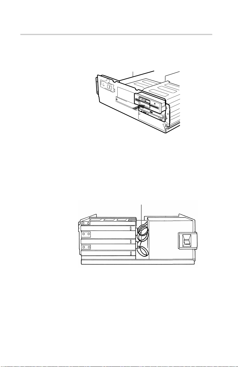
Computer wieder zusammenbauen
1 Installieren Sie das Diskettenlaufwerk wieder im oberen
Laufwerksschacht.
Installieren Sie das
Diskettenlaufwerk.
2 Schließen Sie die Schnittstellenkabel wieder an das
Diskettenlaufwerk an.
3 Befestigen Sie die Schrauben und vorderen Klammern wieder an
den vorgesehenen Stellen.
4 Verstauen Sie die Kabel hinter den Laufwerken, so daß sie nicht
über das Netzteil herausragen.
V erstauen Sie die Kabel
CD-ROM-Laufwerk installieren
98
Netzteil
5 Überprüfen Sie noch einmal folgende Punkte, bevor Sie den
Computer wieder in das Gehäuse schieben und die Schrauben
auf der Rückseite festziehen:
• Sind die Anschlüsse zwischen Laufwerk und Rechner korrekt?
• Wurden die Jumper richtig gesetzt?
6 Befestigen Sie die rückseitige Kunststoffabdeckung, und gehen
Sie gegebenenfalls die einzelnen Schritte im
Installationsabschnitt noch einmal durch.

Treiber installieren
Die mitg elief er te Installationsdiskette enthält zwei Pr ogramme:
• Installationsprogramm
• Gerätetreiber für MS-DOS/Windows 3.1
Hinweis:
Unter MS-DOS- und Windo ws 3.1 benötigt das CDU701-Laufwerk
so wohl die Micr osoft CD-R OM-Erweiterung en (MSCDEX) bzw .
entsprec hende Treiber als auc h den Son y-Gerätetreiber .
V er gewissern Sie sic h also, daß sic h MSCDEX im DOS-V erz eic hnis
Ihrer Festplatte (C:\DOS) befindet, be vor Sie die
Installationsdiskette laden. Möglic herweise müssen Sie sic h die
Software bei Ihrem Händler besor gen. In den meisten aktuellen MSDOS-Versionen (6.2) ist MSCDEX jedoc h v orinstallier t.
Das Installationsprogramm lädt MSCDEX automatisch über die
AUTOEXEC.BAT Datei und installier t den Gerätetreiber über die
CONFIG.SYS Datei, wenn sich MSCDEX bereits auf der Festplatte
im Verzeic hnis C:\DOS befindet.
Installation
Machen Sie Ihr Diskettenlaufwerk A über den Bef ehl
>A:\
an der MS-DOS-Eingabeauff or derung zum aktuellen Laufwerk, und
leg en Sie die Diskette in Laufwerk A ein. Geben Sie “Install” ein.
>A:\install
Drüc ken Sie dann auf die Eingabetaste .
Nac h Absc hluß des Installationsv or gangs enthalten die Dateien
CONFIG.SYS und A UTOEXEC.B AT folg ende zusätzlic he Zeilen:
CONFIG.SYS:
Device=C:\DEV\ATAPI_CD.SYS /D:mscd000 /I:0
AUT OEXEC.BAT:
C:\DOS\MSCDEX.EXE /D:mscd000 /M:12 /V
Treiber installieren
99
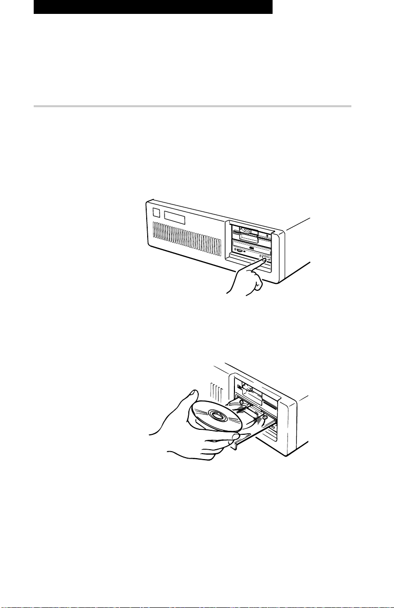
Laufwerk in Betrieb nehmen
In diesem Absc hnitt erfahren Sie , wie Sie das Laufwerk star ten und
eine CD auswerfen.
Laufwerk starten
1 Schalten Sie den Computer ein.
2 Betätigen Sie die Öffnen-/Schließen-Taste.
Der CD-Schlitten wird automatisch ausgefahren.
Betätigen Sie die Öffnen-/
Schließen-Taste
Laufwerk in Betrieb nehmen
100
3 Legen Sie eine CD mit der Beschriftung nach oben in den CD-
Schlitten ein.
Legen Sie eine CD mit der
Beschriftung nach oben ein.
 Loading...