

Page 1

MULTI FORMAT SWITCHER SYSTEM
MVS-8000 System
SWITCHER PROCESSOR PACK
MVS-8400/8300/8200
DME PROCESSOR PACK
MVE-8000
DEVICE CONTROL UNIT PACK
DCU-8000
CENTER CONTROL PANEL PACK
CCP-8000
SYSTEM SETUP MANUAL
1st Edition
Page 2

! WARNING
This manual is intended for qualified service personnel only.
To reduce the risk of electric shock, fire or injury, do not perform any servicing other than that
contained in the operating instructions unless you are qualified to do so. Refer all servicing to
qualified service personnel.
! WARNUNG
Die Anleitung ist nur für qualifiziertes Fachpersonal bestimmt.
Alle Wartungsarbeiten dürfen nur von qualifiziertem Fachpersonal ausgeführt werden. Um die
Gefahr eines elektrischen Schlages, Feuergefahr und Verletzungen zu vermeiden, sind bei
Wartungsarbeiten strikt die Angaben in der Anleitung zu befolgen. Andere als die angegeben
Wartungsarbeiten dürfen nur von Personen ausgeführt werden, die eine spezielle Befähigung
dazu besitzen.
! AVERTISSEMENT
Ce manual est destiné uniquement aux personnes compétentes en charge de l'entretien. Afin de
réduire les risques de décharge électrique, d'incendie ou de blessure n'effectuer que les
réparations indiquées dans le mode d'emploi à moins d'être qualifié pour en effectuer d'autres.
Pour toute réparation faire appel à une personne compétente uniquement.
MVS-8000 System
SYSTEM SETUP
Page 3

Table of Contents
1. System Overview
1-1. Introduction .................................................................................................1-1
1-2. Features ....................................................................................................... 1-1
1-3. System Description .....................................................................................1-2
1-3-1. MVS-8000 .................................................................................. 1-3
1-3-2. MVE-8000..................................................................................1-9
1-3-3. CCP-8000 .................................................................................1-13
1-3-4. DCU-8000 ................................................................................1-21
1-4. MVS-8000 System Example.....................................................................1-24
1-5. Functional Overview .................................................................................1-25
1-5-1. Video Signal Flow....................................................................1-25
2. Installation
2-1. Installation Tasks ........................................................................................2-1
2-2. MVS-8000 Installation................................................................................2-2
2-2-1. Rack Mounting ........................................................................... 2-2
2-3. MVE-8000 Installation................................................................................2-4
2-3-1. Rack Mounting ........................................................................... 2-4
2-4. CCP-8000 Installation .................................................................................2-6
2-4-1. Installation Space .......................................................................2-6
2-4-2. Installing the Main Panel ........................................................... 2-8
2-4-3. Installing the AUX Panel ...........................................................2-9
2-4-4. Installing the Menu Panel...........................................................2-9
2-4-5. Rack Mounting ......................................................................... 2-10
2-5. DCU-8000 Installation ..............................................................................2-13
2-5-1. Rack Mounting ......................................................................... 2-13
2-6. MVS-8000 System Video Cabling............................................................2-15
2-7. MVS-8000 System Control Cabling .........................................................2-16
2-7-1. Cabling ..................................................................................... 2-16
2-7-2. LAN Requirements ..................................................................2-18
2-8. CCP-8000 Panel Cabling ..........................................................................2-19
2-8-1. Connecting the MKS-8075/MKS-8076 ...................................2-22
MVS-8000 System
SYSTEM SETUP
1
Page 4

3. Configuration
3-1. Introduction .................................................................................................3-1
3-2. Basic Configuration Steps...........................................................................3-1
3-3. IP Address ...................................................................................................3-2
3-3-1. Default IP Address ..................................................................... 3-3
3-3-2. Changing IP Address..................................................................3-4
3-4. Ethernet Switch Settings ............................................................................. 3-5
3-5. Software Installation ...................................................................................3-9
3-6. Engineering Setups......................................................................................3-9
3-7. Tally Setup ................................................................................................ 3-10
3-7-1. Setting Router...........................................................................3-12
3-7-2. Setting Group Tally ..................................................................3-24
3-7-3. Setting Wiring .......................................................................... 3-26
3-7-4. Setting Tally Enable .................................................................3-29
3-7-5. Setting Tally Copy ...................................................................3-32
3-7-6. Setting Parallel Tally ................................................................ 3-35
3-7-7. Setting Serial Tally................................................................... 3-37
3-8. Pin Output .................................................................................................3-41
3-8-1. MVS-8000 ................................................................................ 3-41
3-8-2. MVE-8000................................................................................3-43
3-8-3. CCP-8000 .................................................................................3-44
3-8-4. DCU-8000 ................................................................................3-46
4. Specifications
4-1. MVS-8000...................................................................................................4-1
4-2. MVE-8000...................................................................................................4-9
4-3. DCU-8000 .................................................................................................4-11
4-4. CCP-8000 .................................................................................................. 4-13
2
MVS-8000 System
SYSTEM SETUP
Page 5

Section 1
System Overview
1-1. Introduction
The MVS-8000 system has integrated a wide variety of new features including SDTV and HDTV television signal capability, advanced networking and layout-free control panels.
The MVS-8000 system includes SD/HD simulcast, multiple frame rates and resolutions, multi-channel
casting and even broadcast equipment sharing, to name just a few.
The MVS-8000 system is completely ready for smooth integration into current systems, offering the
added quality, reliability and features, needed for the live/post production environment.
The MVS series can be flexibly expanded as a user’s needs grow simply installing the appropriate options
to the basic system.
1-2. Features
Flexible configurations
Item Expandable number Expansion basis
M/E configuration 2 M/E Per M/E
3 M/E
4 M/E
Inputs SD: up to 80 inputs Per 17 inputs
HD: up to 68 inputs
Outputs 56 assignable outputs Per 8 outputs
DME Channel 1 to 8 CH Per 1 CH
(including 8 monitor outputs)
(4 CH in one chassis)
SD/HD capability
High definition Standard definition
1080i/60/59.94/50 480i/59.94
1080PsF/30/29.97/25/24/23.976 576i/50
720p/59.94 (future)
MVS-8000 System
SYSTEM SETUP
1-1
Page 6

1-3. System Description
1-3. System Description
The MVS-8000 System consists of Switcher Processor Pack (MVS-8400/8300/8200), DME Processor
Pack (MVE-8000), Center Control Panel Pack (CCP-8000) and Device Control Unit Pack (DCU-8000).
MVS-8400/8300/8200
CCP-8000
DCU-8000
MVE-8000
MKS-8010
POWER A
AUX PANEL
SYSTEM CONTROL UNIT MKS-8010
MENU PANEL
MIAN PANEL
1-2
MVS-8000 System
SYSTEM SETUP
Page 7
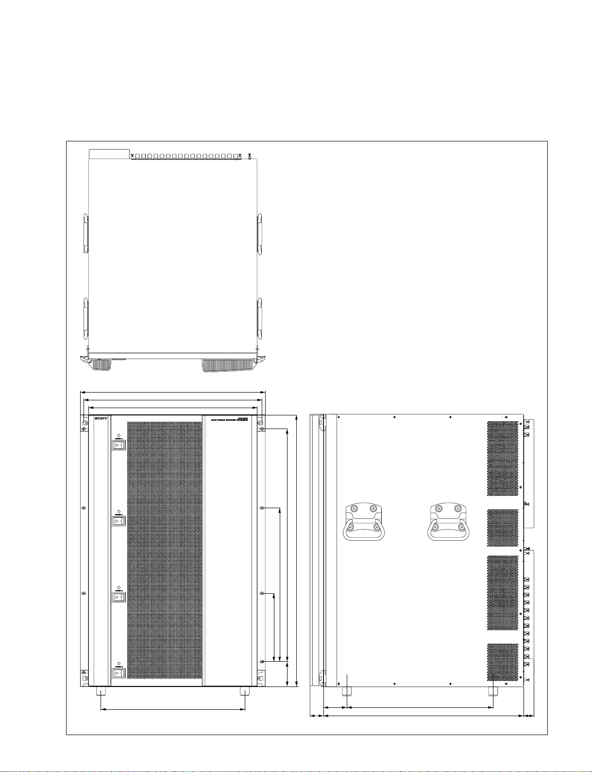
1-3-1. MVS-8000
The MVS-8000 is a 16 rack unit chassis which can be mounted in the standard 483 mm (19 inch) rack.
External dimensions of MVS-8000
1-3. System Description
482
465
440
577.9
708(16U)
400.1
177.8
MVS-8000 System
SYSTEM SETUP
375
65.1
61 380
35
520
27
Unit : mm
1-3
Page 8

1-3. System Description
n
The MVS-8000 has a built-in cooling system consisting of eighteen fans in total fan mounted on the rear
and both sides of the frame, and an air filter on the rear of the front panel. Cooling air is drawn in at the
front side of the frame, through the filter, boards, and modules, and then expelled out the rear and both
sides of the frame at the fan unit.
If dust is accumulated at the intake of the fan or the cables doesn't keep off over 10 cm from the fans, air
is prevented from flowing smoothly that result in rise of temperature inside the machine. It may result in
adverse effects on performance and life of the machine.
MVS-8000
Multi Format Switcher Processor
Fans
Fans
Fans
<Rear Side>
Fans
Fans
Fans
1-4
MVS-8000 System
SYSTEM SETUP
Page 9
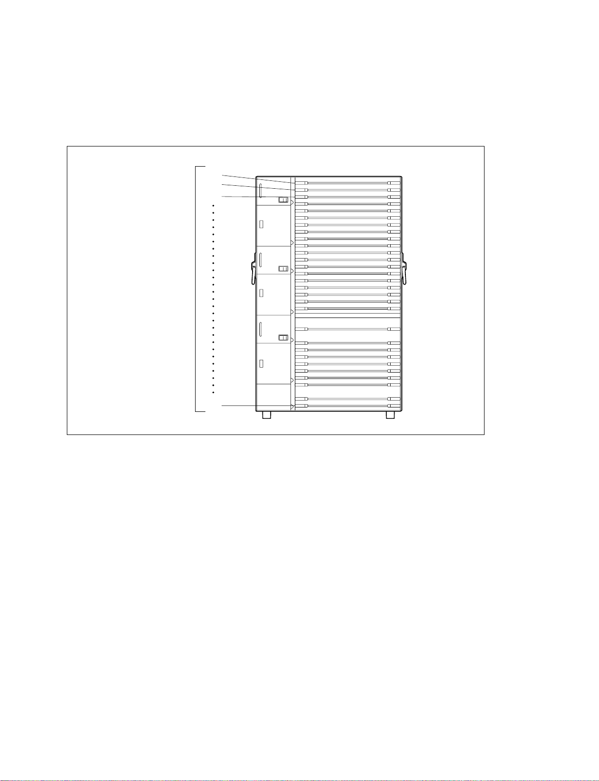
The MVS-8000 has the slots for plug-in boards in its front and rear. It contains of 32 slots in total for
standard/option boards.
n
The MVS-8000 is shown below with the front panel removed. The front panel must remain in place and
closed during normal system operation to keep maximum cooling efficiency.
MVS-8000
Multi Format Switcher Processor
Slots on
the front side
1
2
3
1-3. System Description
32
MVS-8000 System
SYSTEM SETUP
1-5
Page 10
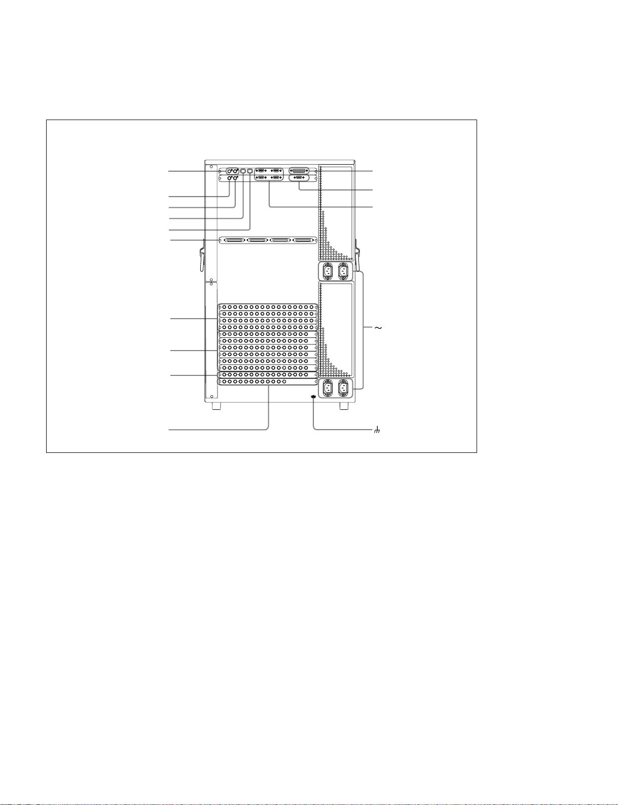
1-3. System Description
Power, control, and video connectors are at the rear chassis of MVS-8000. The illustration below shows a
full loaded rear board. Some of the modules shown below are optional and may not be included in your
system configuration.
MVS-8000
Multi Format Switcher Processor
REF INPUT connectors
REF OUTPUT connectors
EXT connector
DATA connector
CTRL connector
DME 1A, 1B, 2A, 2B connectors
PRIMARY INPUTS
1 to 68 connectors
OUTPUTS 1 to 48 connectors
MONITOR OUTPUTS
49 to 56 connectors
PRIMARY INPUTS
69 to 80 connectors
GPI connector
TERMINAL connector
REMOTE 1 to 4 connectors
AC IN A, B, C, and
D connectors
terminal
1-6
MVS-8000 System
SYSTEM SETUP
Page 11

MVS-8000 options
The following lists the plug-in boards that may be purchased as options.
MVS-8000 option configuration
Front side
Option name Board name Slot No. Descriptions
MKS-8210HD/SD DO-41/DO-42 3, 7, 12, 16 Mix/Effect Board Set
MIX-45 4, 8, 13, 17 M/E1: Slot 12 to 15
KPC-16 5, 9, 14, 18 M/E2: Slot 7 to 10
DI-40/DI-41 6, 10, 15, 19 M/E3: Slot 3 to 6
M/E4: Slot 16 to 19
MKS-8170HD/SD DIF-119/DIF-122 11 DME I/F Board
MKS-8160HD/SD OUT-23/OUT-24 24 to 29 8 Outputs Board
1 to 8 output: Slot 24
9 to 16 output: Slot 25
17 to 24 output: Slot 26
25 to 32 output: Slot 27
33 to 40 output: Slot 28
41 to 48 output: Slot 29
MKS-8440HD/SD DIO-62/DIO-63 31 Frame Memory Board Set
MY-102 32
1-3. System Description
Rear side
Option name Board name Printed characters Description
MKS-8110HD/SD CNI-9/CNI-10 IN 1 to 17 17 Inputs Board
MKS-8160HD/SD CNO-11/CNO-17B 8 Outputs Board
MKS-8161HD/SD CNO-12/CNO-17A OUT 49 to 56 8 Monitor Outputs Board
MKS-8111SD CNI-17 IN 69 to 80 12 Additional Input Board
IN 18 to 34
IN 35 to 51
IN 52 to 68
I
nsert a real board into the slot that corresponds
to the slot in the front.
MVS-8000 System
SYSTEM SETUP
1-7
Page 12

1-3. System Description
Power supply unit
The MVS-8000 Power Supply Units are supplied with MVS-8000 processor.
Three power supply units are required to run the MVS-8000 system. An optional fourth unit is added to
provide redundant power. With fourth unit mounted, one unit can fail without causing system failure.
It is recommended that each unit’s AC input be connected to the AC supply circuit of a separated power
source system. Any unit (s) for which a separate power source system is not available, is (are) recommended to be connected to a UPS (Uninterruptible Power Supply).
Option
Option name Description
HK-PSU04 Power Supply Unit
The power cord is not supplied with the MVS-8000.
It is necessary that the power cord should be applicable to places in the area.
Power cord
Area Specification Length Part No.
Japan 125 V 10 A 2.5 m 1-776-997-11
*3P - 2P (adaptor) *1-750-686-11
USA/Canada 125 V 10 A 2.4 m 1-557-377-11
All Europian countries 250 V 10 A 2.4 m 1-782-929-21
1-8
MVS-8000 System
SYSTEM SETUP
Page 13
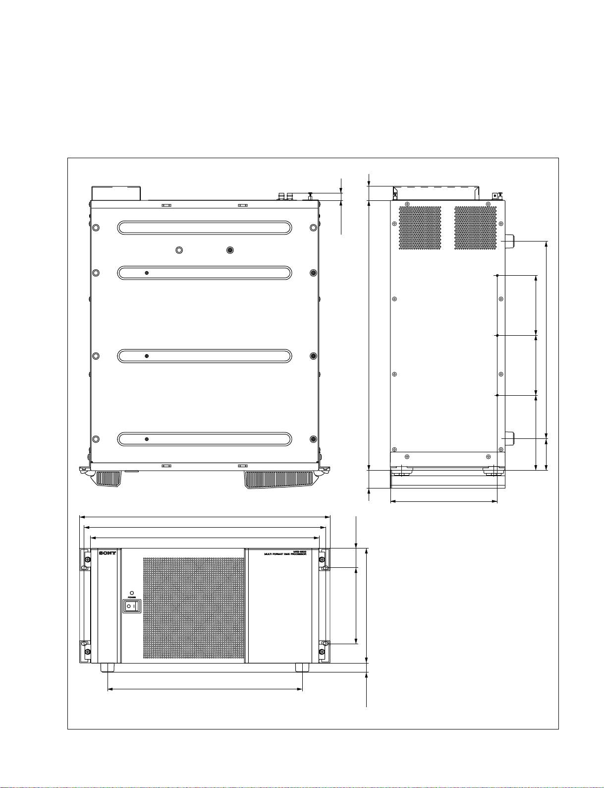
1-3. System Description
1-3-2. MVE-8000
MKS-8800 (Mutlti Format DME Processor) is a 5 rack unit chassis which can be mounted in the standard 483 mm (19
inch) rack.
External dimensions of MKS-8800
14.5
115.5115.5144.5
482
465
440
146.2 37.4
221 (5U)
520
35 27
38061
206
MVS-8000 System
SYSTEM SETUP
375
17.5
Unit : mm
1-9
Page 14
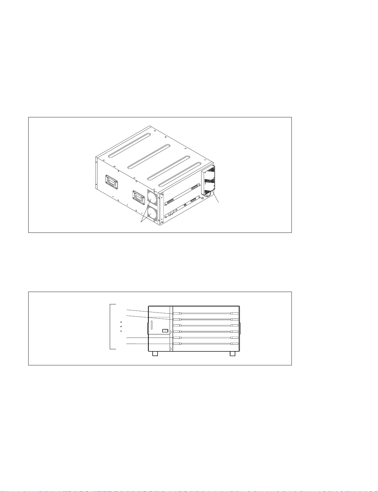
1-3. System Description
n
The MVE-8000 has a built-in cooling system consisting of four fans in total mounted on the rear and right
side of the frame, and an air filter on the rear of the front panel. Cooling air is drawn in at the front side of
the frame, through the filter, boards, and modules, and then expelled out the rear and right side of the
frame at the fan unit.
If dust is accumulated at the intake of the fan or the cables doesn't keep off over 10 cm from the fans, air
is prevented from flowing smoothly that result in rise of temperature inside the machine. It may result in
adverse effects on performance and life of the machine.
MVE-8000
DME Processor Pack
Fans
Fans
The MVE-8000 has the slots for plug-in boards in its front and rear. It contains of 6 slots in total for
standard/option boards.
n
The MVE-8000 is shown below with the front panel removed. The front panel must remain in place and
closed during normal system operation to keep maximum cooling efficiency.
MVE-8000
DME Processor Pack
Slots on
the front side
1
2
5
6
1-10
MVS-8000 System
SYSTEM SETUP
Page 15
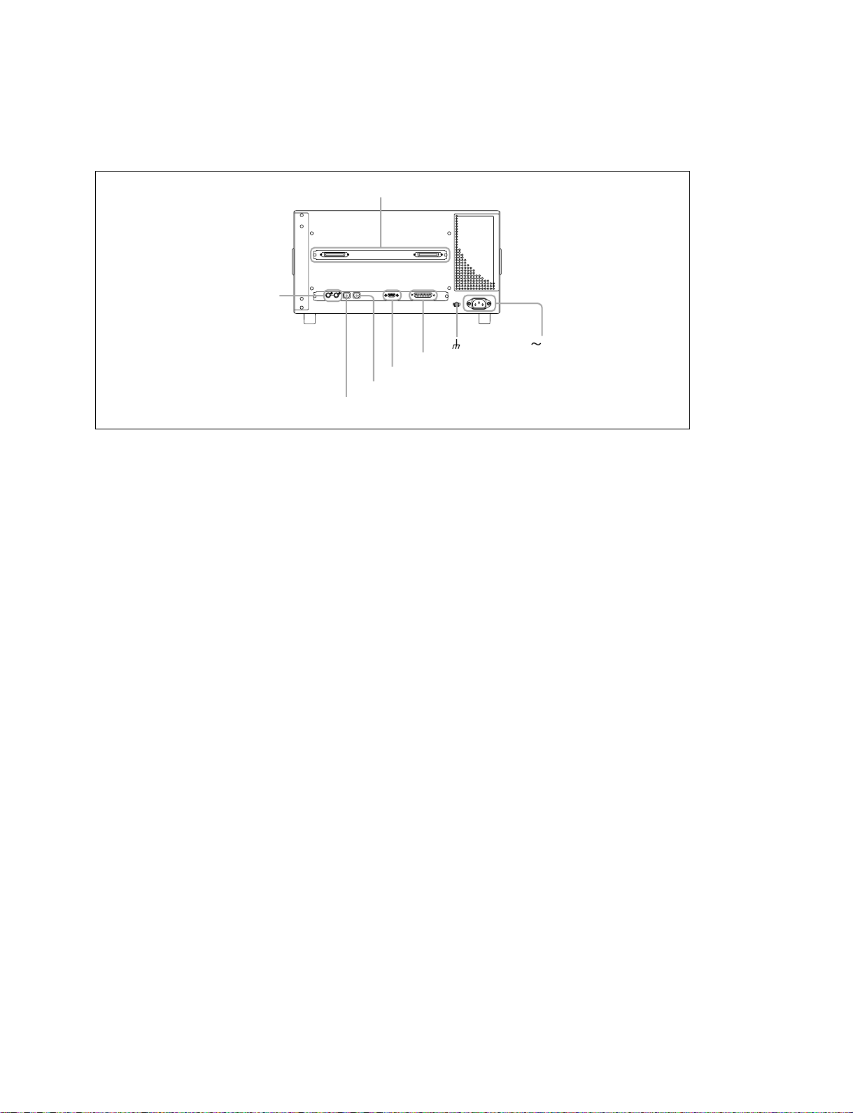
Power, control, and video connections are at the rear of MVE-8000. The illustration below shows a full
loaded rear board. Some of the modules shown below are optional and may not be included in your
system configuration.
1-3. System Description
MVE-8000
DME Processor Pack
REF INPUT connectors
SWITCHER A and B connectors
terminal
GPI connector
EDITOR connector
CTRL connector
DATA connector
AC IN connector
MVS-8000 System
SYSTEM SETUP
1-11
Page 16

1-3. System Description
MVE-8000 options
The following lists the plug-in boards that may be purchased as options.
MVE-8000 option configuration
Front side
Option name Board name Slot No. Descriptions
MKS-8810M DVP-21 1 to 2, 4 to 5 Basic Effect Board
(MKS-8830M) (VSE-39: daughter board) CH1: Slot 1
CH2: Slot 2
CH3: Slot 4
CH4: Slot 5
MKS-8820M VIF-26 3 Input/Output Board
Rear side
Option name Board name Slot No. Descriptions
MKS-8820M CN-2153 _ Input/Output Board
Insert a real board into the slot that corresponds
to the slot in the front.
Power supply unit
The MVE-8000 Power Supply Unit is supplied with MVE-8000 processor.
One power supply unit is required to run the system.
The power cord is not supplied with the MVE-8000.
It is necessary that the power cord should be applicable to places in the area.
Power cord
Area Specification Length Part No.
Japan 125 V 10 A 2.5 m 1-776-997-11
USA/Canada 125 V 10 A 2.4 m 1-557-377-11
All Europian countries 250 V 10 A 2.4 m 1-782-929-21
*3P - 2P (adaptor) *1-750-686-11
1-12
MVS-8000 System
SYSTEM SETUP
Page 17

1-3-3. CCP-8000
The modular design of MVS-8000 system control panel provides flexibility for locating the desired
module in their preferred area of each M/E base plate. M/E base plates are offered in the three types of
16, 24 and 32 button style, while M/E bank are available in 2 M/E, 3 M/E, and 4M/E configuration.
It also have some module of DME control, Key Frame Control, Memory Card/USB, Flexi Pad and etc.
The CCP-8000 consists of System Control Unit (MKS-8010), Menu Panel (MKS-8011), and Main Panel.
System Control unit (MKS-8010) is a 3 rack unit chassis, which can be mounted in the standard 483 mm
(19 inch) rack.
CCP-8000
MKS-8010
SYSTEM CONTROL UNIT MKS-8010
POWER A
MENU PANEL
AUX PANEL
1-3. System Description
CCP-8000 IM
MIAN PANEL
Main panel
The main panel, comprised of various types of operation modules, provides the operating controls of the
system. It can be fleely laid out, with variable numbers of M/E banks (2 to 4) and cross-point buttons (16,
24 or 32) and variable layout of the AUX bus module. Operation modules can be mounted in the MKS8075 Extension Adaptor and MKS-8076 Memory Card/USB Adaptor for installation apart from the main
panel. The AUX bus module can also be removed from the main panel and used as an AUX panel.
Menu panel (MKS-8011)
The menu panel provides a GUI interface for operating the menus.
MVS-8000 System
SYSTEM SETUP
1-13
Page 18

1-3. System Description
System control unit (MKS-8010)
The system control unit provides control functions for the center control panel as a whole. It also supplies
power to the various panels
Shows the modules for CCP-8000.
Model Name Description
MKS-8013 32 AUX Bus Module
MKS-8014 24 AUX Bus Module
MKS-8015 16 AUX Bus Module
MKS-8017 32 XPT Module
MKS-8018 24 XPT Module
MKS-8019 16 XPT Module
MKS-8020 Standard Transition Module
MKS-8021 Simple Transition Right Module
MKS-8022 Simple Transition Left Module
MKS-8023 Compact Key Transition Module
MKS-8024 Flexi Pad Module
MKS-8025 Memory Card/USB Module
MKS-8026 10 Key Pad Module
MKS-8030 Key Frame Module
MKS-8031TB Track Ball Module
MKS-8032 DSK Fader Module
MKS-8034FB FTB Module
MKS-8035 Key Control Module
MKS-8031JS Joy Stick Module
MKS-8033 Utility/Shotbox Module
Main panel
Main Panel installation requires careful attention to the console support structure and the console cutout
dimensions necessary to accommodate the mounting flanges located on the front and sides of the tub.
Menu panel (MKS-8011)
The Menu Panel includes a touch screen display, buttons for accessing menus, and knobs for adjusting
parameter values.
n
The Main Panel weighs approximately 16 to 30 kg (depending on the configuration). Prior to installation,
ensure that your console is structurally capable of supporting the Main Panel.
The Main Panel was designed to be flush mounted in a console, but it may also be surface mounted to be
protruded above the surface of the console.
1-14
MVS-8000 System
SYSTEM SETUP
Page 19
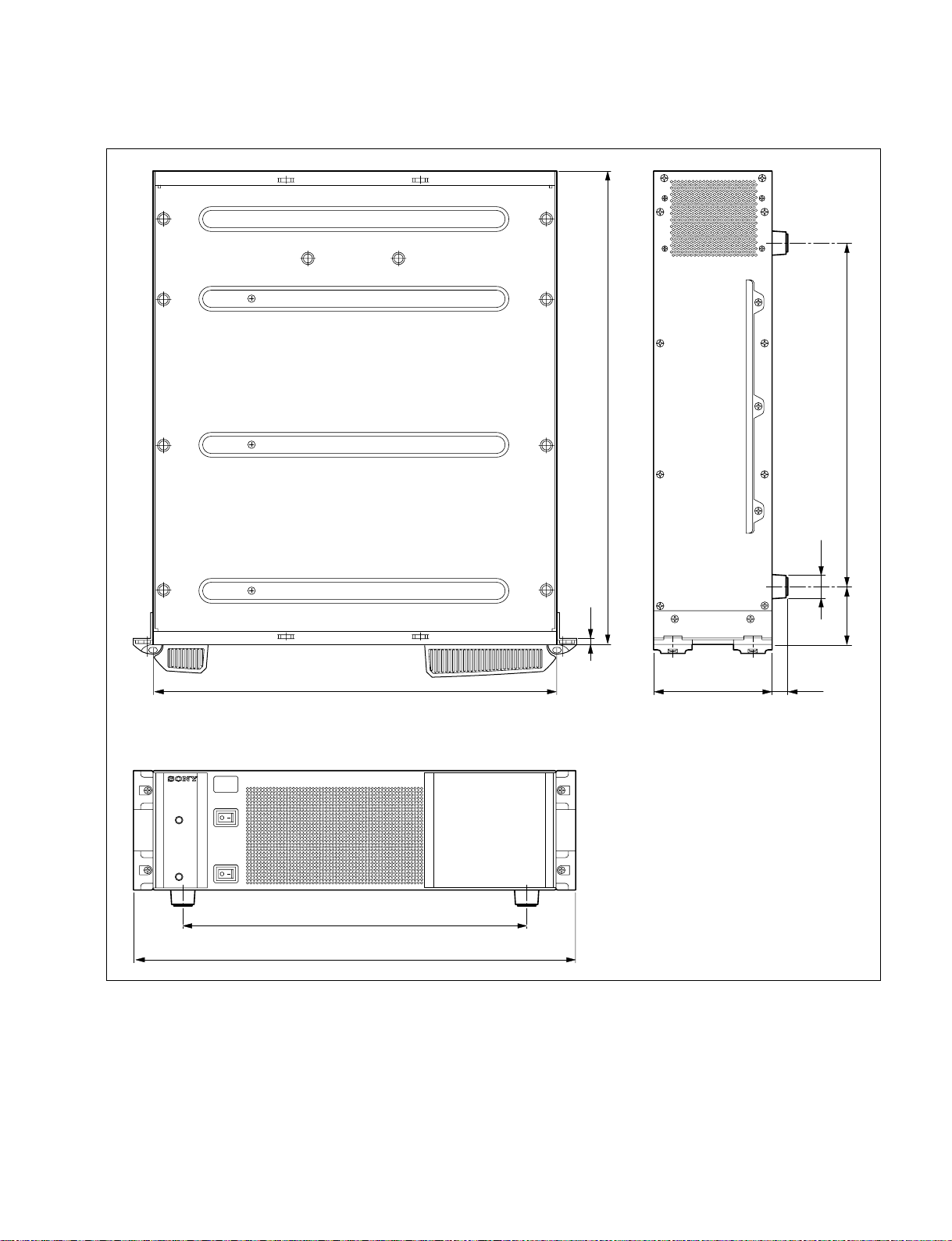
External dimensions of MKS-8010
1-3. System Description
POWER A
POWER B
520
7
440 132.4
SYSTEM CONTROL UNIT MKS-8010
38061
ø26
17.5
MVS-8000 System
SYSTEM SETUP
375
482
Unit : mm
1-15
Page 20
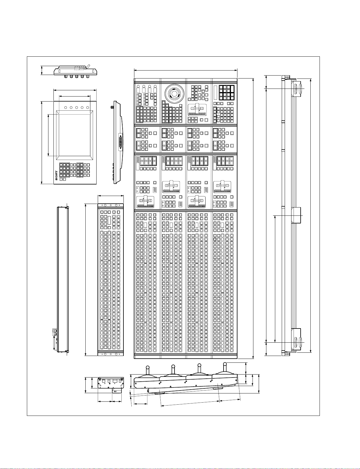
1-3. System Description
External dimensions of main panel/AUX panel/menu panel MKS-8011
46
424
213
220
160
132
528
1444
69.569.5
1304
1407
1-16
782
80
57
652
49 59.7
73
4873
9.5
72
300
104
59
98
Unit : mm
MVS-8000 System
SYSTEM SETUP
Page 21
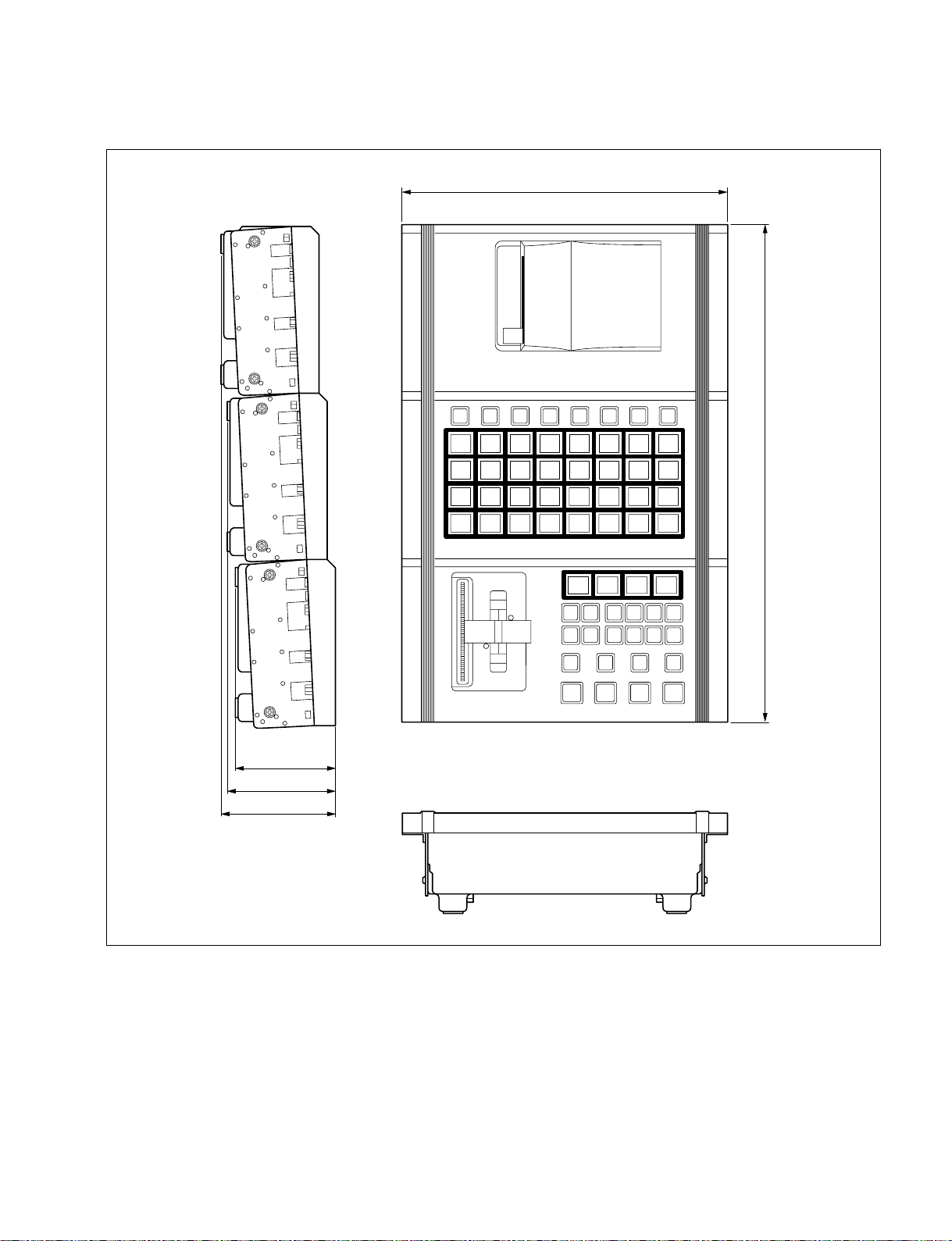
External dimensions of extension adaptor MKS-8075/memory card/USB adaptor MKS-8076
263
396
1-3. System Description
MVS-8000 System
SYSTEM SETUP
79
85
91
Unit : mm
1-17
Page 22
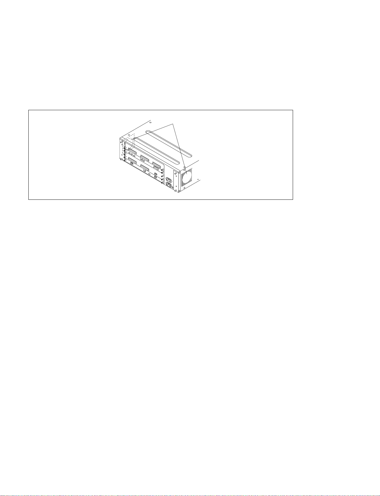
1-3. System Description
n
The MKS-8010 has a built-in cooling system consisting of a fan mounted on the both sides of the frame,
and an air filter on the rear of the front panel. Cooling air is drawn in at the front side of the frame,
through the filter, boards, and modules, and then expelled out the both sides of the frame at the fan unit.
If dust is accumulated at the intake of the fan or the cables doesn’t keep over 10 cm from the fans, air is
prevented from flowing smoothly that result in rise of temperature inside the machine. It may result in
adverse effects on performance and life of the machine if used in such an environment.
MKS-8010
System Control Unit
Fans
1-18
MVS-8000 System
SYSTEM SETUP
Page 23
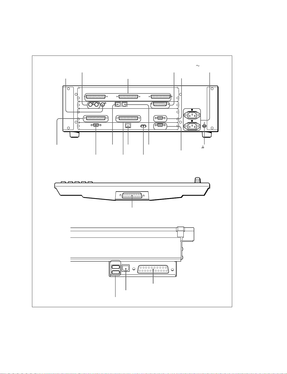
Power, control, and video connectors are at the rear of system control unit (MKS-8010), the main panel
and menu panel (MKS-8011).
The illustration below shows a full loaded rear board.
1-3. System Description
MKS-8010
REMOTE connector
MENU PANEL connector
Menu Panel
REF IN connector
EXT PANEL1
MENU PANEL MAIN PANEL
EXT DISPLAY EDITOR PANEL
EXT DISPLAY
connector
EXT PANLE1 to 3 connector
EXT PANEL2
CTRL
PERIPH
DATA DEVICE
CTRL
connector
MAIN PANEL
connector
DATA
connector
DEVICE
connector
GPI connector
receptacle
LTC IN connector
AC IN A, B
EXT PANEL3
GPIREF IN REMOTE
LTC IN
A
B
AC IN
PERIPH connector terminal
EDITOR PANLE
connector
Main Panel
SCU connector
HOSTDEVICE
HOST connector
DEVICE connector
SCU
SCU connector
MVS-8000 System
SYSTEM SETUP
1-19
Page 24

1-3. System Description
Power supply unit
The CCP-8000 Power Supply Units is supplied with System Control Unit (MKS-8010).
A power supply units is required to run the system. An optional second unit is added to provide redundant
power. With second unit mounted, one unit can fail without causing system failure.
It is recommended that each unit’s AC input be connected to the AC supply circuit of a separated power
source system. Any unit (s) for which a separate power source system is not available, is (are) recommended to be connected to a UPS (Uninterruptible Power Supply).
Option
Option name Description
HK-PSU03 Backup Power Supply Unit
The power cord is not supplied with the CCP-8000.
It is necessary that the power cord should be applicable to places in the area.
Power cord
Area Specification Length Part No.
Japan 125 V 10 A 2.5 m 1-776-997-11
*3P - 2P (adaptor) *1-750-686-11
USA/Canada 125 V 10 A 2.4 m 1-557-377-11
All Europian countries 250 V 10 A 2.4 m 1-782-929-21
1-20
MVS-8000 System
SYSTEM SETUP
Page 25
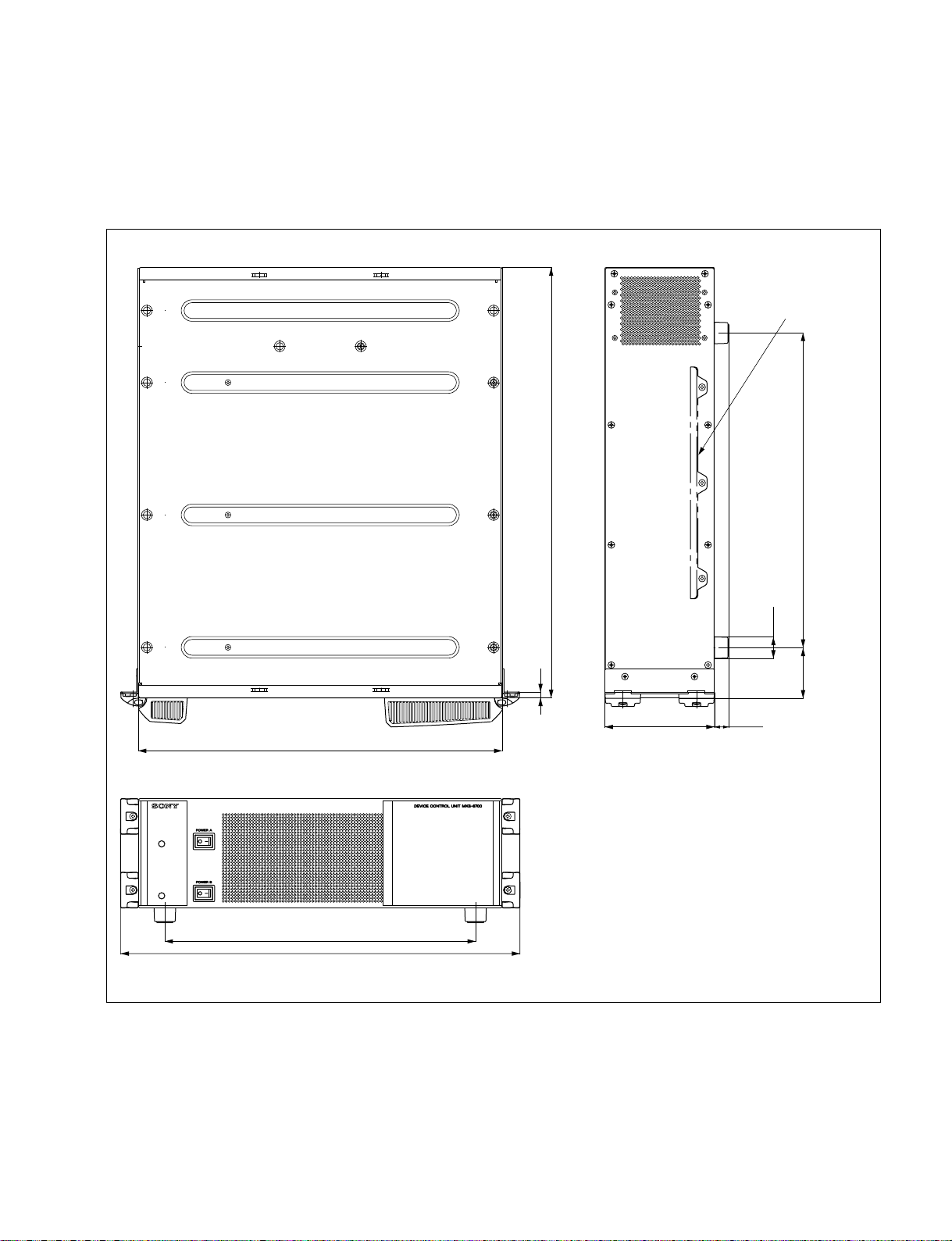
1-3-4. DCU-8000
7
520
440
482
375
17.5
380
61
ø26
132.4
Rack mount metal
(supplied with RMM-10)
DCU-8000 is a 3 rack unit chassis which can be mounted in standard 483 mm (19 inch) rack.
External dimensions of DCU-8000
1-3. System Description
Unit : mm
MVS-8000 System
SYSTEM SETUP
1-21
Page 26
1-3. System Description
n
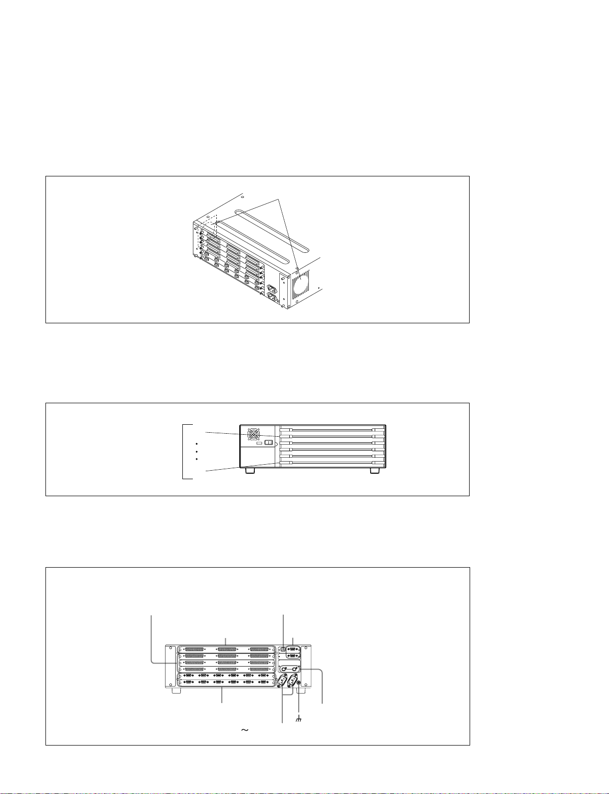
The DCU-8000 has a built-in cooling system consisting of a fan mounted on the both sides of the frame,
and an air filter on the rear of the front panel. Cooling air is drawn in at the front side of the frame,
through the filter, boards, and modules, and then expelled out the both sides of the frame at the fan unit.
If dust is accumulated at the intake of the fan or the cables doesn't keep off over 10 cm from the fans, air
is prevented from flowing smoothly that result in rise of temperature inside the machine. It may result in
adverse effects on performance and life of the machine if used in such an environment.
DCU-8000
Device Control Unit
Fans
DCU-8000 has front and rear boards. It consists of 6 slots for standard/option boards.
n
The DCU-8000 is shown below with the front panel removed. The front panel must remain in place and
closed during normal system operation to keep maximum cooling efficiency.
DCU-8000
Device Control Unit
2
Slots on
the front side
6
Power, control, and video connections are at the rear of DCU-8000. The illustration below shows a full
loaded rear board. Some of the modules shown below are optional and may not be included in your
system configuration.
DCU-8000
Device Control Unit
TALLY/GPI OUT 1 to 18,
19 to 36, 37 to 54 connectors
TALLY/GPI IN 1 to 34,
35 to 68, 69 to 102 connectors
REMOTE 1 to 6 connectors
PERIPH connector
SERIAL TALLY 1 and 2 connectors
REF IN connectors
terminal
AC IN A and B connectors
1-22
MVS-8000 System
SYSTEM SETUP
Page 27

DCU-8000 options
The following lists the plug-in boards that may be purchased as options.
DCU-8000 option configuration
Front Side
Option name Board name Slot No. Descriptions
MKS-8701 RC-90 2 to 6 Tally/GPI output Board
MKS-8702 IF-848 2 to 6 Serial Interface Board
Rear side
Option name Board name Slot No. Descriptions
MKS-8701 CN-2195 _ Tally/GPI output Board
Install the board into the slot in the real that
corresponds to a RC-90 board that is inserted
in the slot in the front.
MKS-8702 CN-2194 _ Serial Interface Board
Install the board into the slot in the real that
corresponds to a IF-848 board that is inserted
in the slot in the front.
1-3. System Description
Power supply unit
The DCU-8000 Power Supply Units is supplied with DCU-8000 processor.
A power supply units is required to run the system. An Optional second unit is added to provide redundant power. With second unit mounted, one unit can fail without causing system failure.
It is recommended that each unit’s AC input be connected to the AC supply circuit of a separated power
source system. Any unit (s) for which a separate power source system is not available, is (are) recommended to be connected to a UPS (Uninterruptible Power Supply).
Option
Option name Description
HK-PSU03 Backup Power Supply Unit
The power cord is not supplied with the DCU-8000.
It is necessary that the power cord should be applicable to places in the area.
Power cord
Area Specification Length Part No.
Japan 125 V 10 A 2.5 m 1-776-997-11
USA/Canada 125 V 10 A 2.4 m 1-557-377-11
All Europian countries 250 V 10 A 2.4 m 1-782-929-21
*3P - 2P (adaptor) *1-750-686-11
MVS-8000 System
SYSTEM SETUP
1-23
Page 28
1-4. MVS-8000 System Example
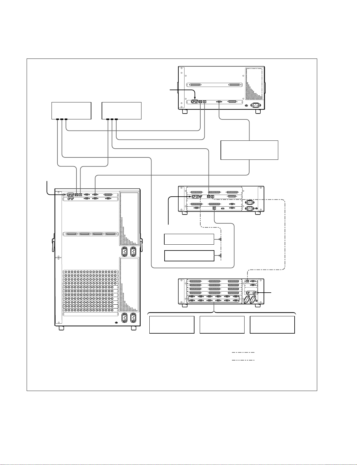
1-4. MVS-8000 System Example
Reference video signal (*2)
Ethernet switch
Reference video
signal (*2)
DATA CTRL REMOTE 1
(*1)
Ethernet switch
(*1)
DATA LAN
REMOTE
Reference video
signal (*2)
BKS-R series
HDS-X series
Device Control Unit Pack DCU-8000
CTRL
EDITOR
Editing Control System
CTRL
DATA
DME Processor Pack
MVE-8000
BVE-9100
PERIPH
System Control Unit
MKS-8010
PERIPH
Reference video
signal (*2)
VTR DDR
Switcher Processor Pack
MVS-8400/8300/8200
(*1) : Connect each LAN (CTRL, DATA) to the separate Ethernet switches respectively.
However, a single Ethernet switch can be used for connecting each LAN.
For information about Ethernet switches that can be used in an MVS system, contact your local Sony Sales Office/Service Center.
For detailed information about setting up the Ethernet switch, refer to the documentation supplied with the switch.
(*2) : Terminate the system with the 75 Z terminator supplied. The 75 Z terminator is supplied with the equipment.
Audio mixer
Crossover cable
BNC cable
1-24
MVS-8000 System
SYSTEM SETUP
Page 29
1-5. Functional Overview
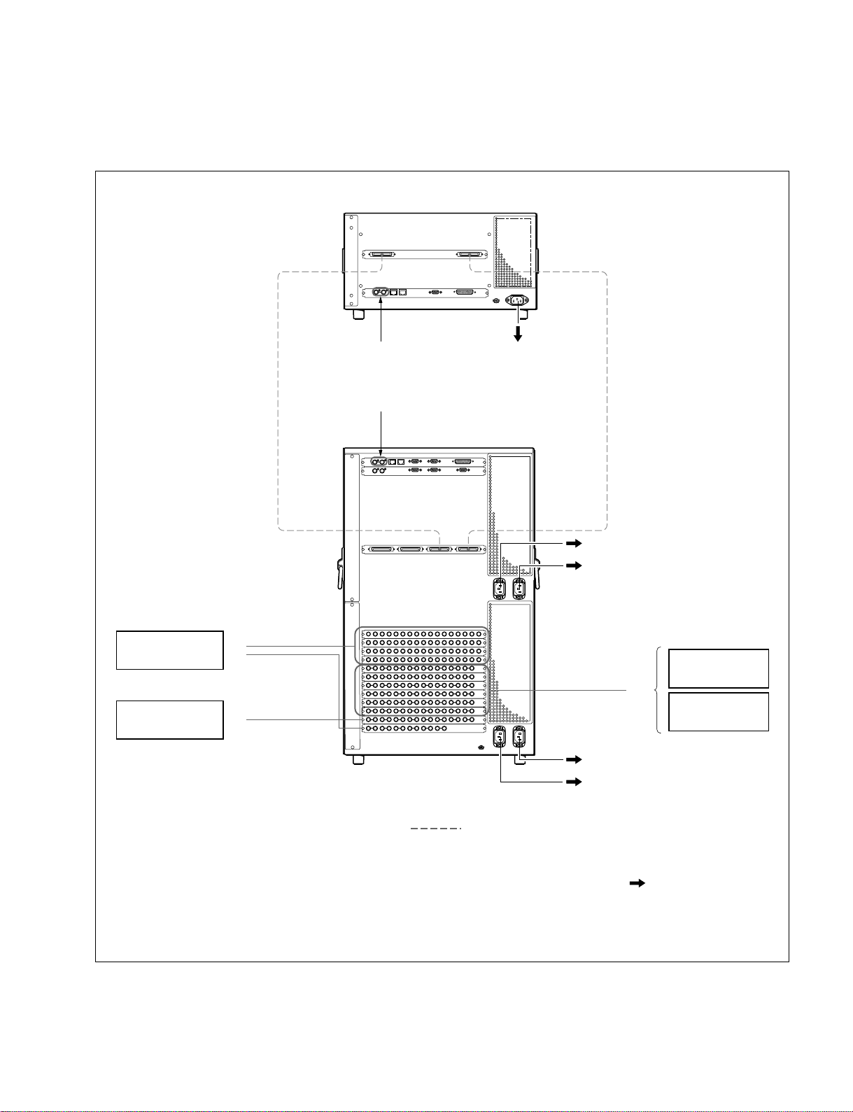
1-5-1. Video Signal Flow
1-5. Functional Overview
DME Processor Pack
MVE-8000
SWITCHER ASWITCHER B
Camera
VTR
Routing Switcher
MONITOR
5
DME 1B
PRIMARY INPUTS
1 to 68
8
PRIMARY INPUTS
69 to 80
MONITOR OUTPUTS
8
1 to 8
Reference video
signal (*3)
Reference video signal (*3)
AC100 to 240 V Power Supply (*1)
DME 1A
AC100 to 240 V Power Supply (*2)
AC100 to 240 V Power Supply (*2)
OUTPUTS 1 to 48
5
MONITOR
8
VTR
AC100 to 240 V Power Supply (*2)
Switcher Processor Pack
MVS-8400/8300/8200
75-pin Cable
(*1) : For the AC power cord, refer to “Optional Items” of the “DME Processor Pack MVE-8000” Operation Manual.
(*2) : For the AC power cord, refer to “Optional Items” of the “Multi-Format Switcher Processor MVS-8000” Operation Manual.
(*3) : Terminate the system with the 75 Z terminator supplied with this unit.
MVS-8000 System
SYSTEM SETUP
AC100 to 240 V Power Supply (*2)
Video Signal Input
8
Video Signal Output
Video/Key Signal
5
AC Power Supply
1-25
Page 30

Page 31

Section 2
Installation
2-1. Installation Tasks
Installation tasks should be completed in the following order:
1. Unpack equipment
2. Install the CCP-8000 main panel, the Menu Panel (MKS-8011) and the AUX panel (separate unit
only) and System Control Unit (MKS-8010).
3. Install the switcher processor, DME processor, and DCU.
4. Connect cables and configure internal system communications (including Ethernet and IP address.)
5. Connect cables to video inputs and outputs, DME V/K.
6. Connect the power cables.
7. Test that the power supply system works correctly and communications are established correctly in
the system.
8. Test basic system for proper operation
9. Cable external interface (including Tally and GPI).
10. Configure external interface.
11. Test external interfaces for proper operation
MVS-8000 System
SYSTEM SETUP
2-1
Page 32

2-2. MVS-8000 Installation
2-2. MVS-8000 Installation
2-2-1. Rack Mounting
The MVS-8000 can be mounted in the 19-inch standard
rack.
To mount the MVS-8000 series in the rack, use the
specified rack mount parts that are supplied with the MVS8000 series and follow the procedure described below.
n
If a rack mount parts other than the specified ones are
used, the unit may not be mounted in the 19-inch standard
rack.
Specified rack mount parts
. Support angle 2 pcs
. Bracket 4 pcs
. Support angle fixing screw 8 pcs
(PSW4 x 10 : 7-682-962-01)
. Bracket fixing screw 8 pcs
(B4 x 10 : 7-682-562-04)
2. Rack mounting procedure
This section describes the rack mounting procedure using
the dedicated system rack mount kit of the MVS-8000.
n
Use the following torque to tighten the screws finally.
Tightening torque : 120 x 10_2 N.m {12.2 kgf.cm}
1. Attach the bracket to the support angle using the
specified four screws.
2. Loosen the screws on the front and rear of the right
and left brackets. Adjust the length of the brackets
according to the depth of the rack.
(The illustration below shows the left bracket.)
Bracket
Support angle
1. Precautions for rack mounting
w
. To prevent the rack from falling or moving, fix the rack
on a flat and steady floor using bolt or others.
If the rack falls due to the weight of the equipment, it
may cause death or injury.
. Be sure to use the specified rack mount parts.
If not, injury may result and the equipment may fall due
to insufficient strength.
. After rack mounting, be sure to tighten the screws on the
rack angle and fix the unit in the rack.
If the screws on the angle are not tightened, the unit may
slip from the rack and fall, causing injury.
c
When mounting the unit in the rack, note the following:
. Be sure to mount in the rack with four persons or more.
. Be careful not to catch your fingers or hands in the rack
mount rail or others.
. Mount in the rack in a stable position.
PSW4 x 10
PSW4 x 10
Bracket
n
Maximum depth of bracket : 750 mm
Minimum depth of bracket : 595 mm
n
If several units are mounted in a rack, it is recommended to
install a ventilation fan to prevent temperature rise inside
the rack.
2-2
MVS-8000 System
SYSTEM SETUP
Page 33
2-2. MVS-8000 Installation
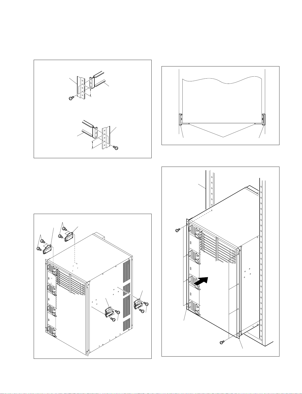
3. Attach the right and left brackets to the rack completely using the specified eight screws.
(The illustration below shows the left bracket.)
Front side
Rack
Bracket
31.75
B4 x 10
Rear side
Rack
Bracket
31.75
B4 x 10
Unit : mm
4. Tighten the screws (four screws each on the right and
left) for adjusting the length of the bracket completely
(the screws that were loosened in step 2).
5. Remove the front panel.
6. Remove the 16 screws and remove the handles (two
handles each on the right and left) from both sides of
the MVS-8000.
7.
Place the right and left bottom ends of the MVS-8000 on
the support angles, and slide the equipment to the rear.
n
The support angles support the equipment as shown below.
Bracket Bracket
Support angles
8. Fix the rack angles of the equipment to the rack using
the specified eight screws.
Rack
Handle
RK5 x 10
RK5 x 10
Handle
Handle
RK5 x 10
B5 x 12
Handle
RK5 x 10
Rack angle
B5 x 12
Rack angle
MVS-8000 System
SYSTEM SETUP
9. Attach the front panel to the equipment.
2-3
Page 34
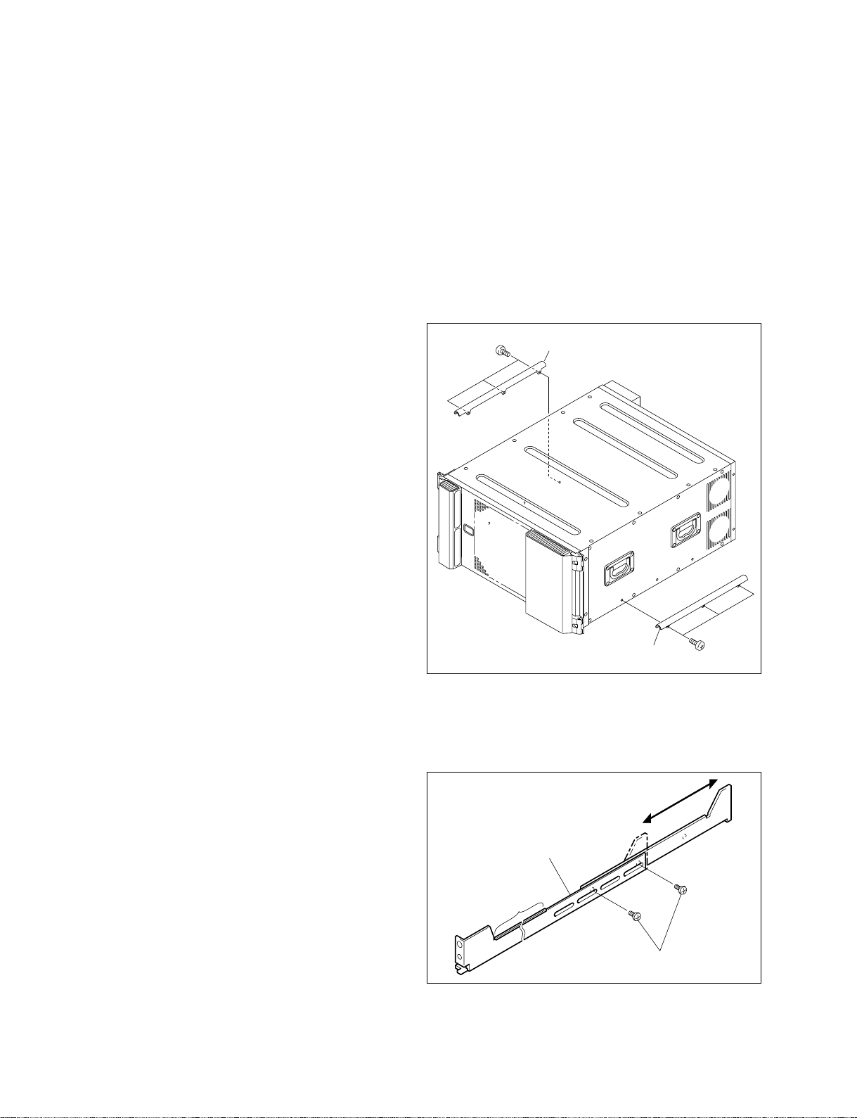
2-3. MVE-8000 Installation
2-3. MVE-8000 Installation
2-3-1. Rack Mounting
The MVE-8000 can be mounted in the 19-inch standard
rack.
To mount the MVE-8000 in the rack, use the specified rack
mount kit and follow the procedure described below.
Specified rack mount kit : RMM-10
n
If a rack mount kit other than the specified one is used, the
unit may not be mounted in the 19-inch standard rack.
Parts of the RMM-10
. Rack tools 2 pcs
. Right rack mount adaptor 1 pc
. Left rack mount adaptor 1 pc
. Rack tool attaching screws 6 pcs
(B4 x 6 : 7-682-560-09)
. Rack tool attaching screws 6 pcs
(B4 x 10 : 7-682-560-10)
2. Rack mounting procedure
This section describes the rack mounting procedure using
the RMM-10 rack mount kit.
n
Tighten the screws to the following torque.
Tightening torque : 120 x 10_2 N.m {12.2 kgf.cm}
1. Attach the rack tool to the side of the equipment using
the specified six screws.
n
Use B4 x 6 screws.
B4 x 6
Rack tool
1. Precautions for rack mounting
w
. To prevent the rack from falling or moving, fix the rack
on a flat and steady floor using bolt or others.
If the rack falls due to the weight of the equipment, it
may cause death or injury.
. Be sure to use the specified rack mount kit.
If not, injury may result and the equipment may fall due
to insufficient strength.
. After rack mounting, be sure to tighten the screws on the
rack angle and fix the unit in the rack.
If the screws on the rack angle are not tightened, the unit
may slip from the rack and fall, causing injury.
c
When mounting the unit in the rack, note the following:
. Be sure to mount in the rack with two persons or more.
. Be careful not to catch your fingers or hands in the rack
mount rail or others.
. Mount in the rack in a stable position.
n
If several units are mounted in a rack, it is recommended to
install a ventilation fan to prevent temperature rise inside
the rack.
Rack tool
B4 x 6
2. Loosen the screws on the rear of the right and left
adaptors and adjust the length of the adaptor according
to the depth of the rack.
(The illustration below shows the left adaptor.)
Adaptor
Portion of
the rail
B4 x 6
n
Maximum depth of adaptor :750 mm
Minimum depth of adaptor : 595 mm
2-4
MVS-8000 System
SYSTEM SETUP
Page 35
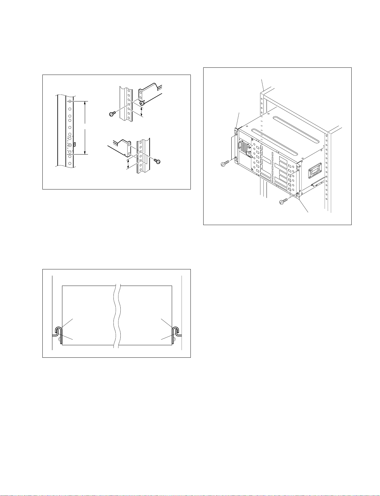
2-3. MVE-8000 Installation
3. Attach the right and left adaptors to the rack completely using the specified six screws.
(The illustration below shows the left adaptor.)
B4 x 10
3U
31.75
31.75
B4 x 10
Unit : mm
4. Tighten the screws (B4 x 6 : two screws each on the
right and left) for adjusting the length of the adaptor
completely (the screws that were loosened in step 2).
5. Align the groove of the rack tool at the side of the
equipment with the rail, and slide the equipment to the
rear.
n
The rack tools are hooked on the rails as shown below.
7. Fix the rack angle in the rack using the specified
screws.
Rack
Rack angle
B5 x 12
B5 x 12
Rack angle
8. Attach the front panel to the equipment.
Rack tool
Rail Rail
6. Remove the front panel.
MVS-8000 System
SYSTEM SETUP
Rack tool
2-5
Page 36
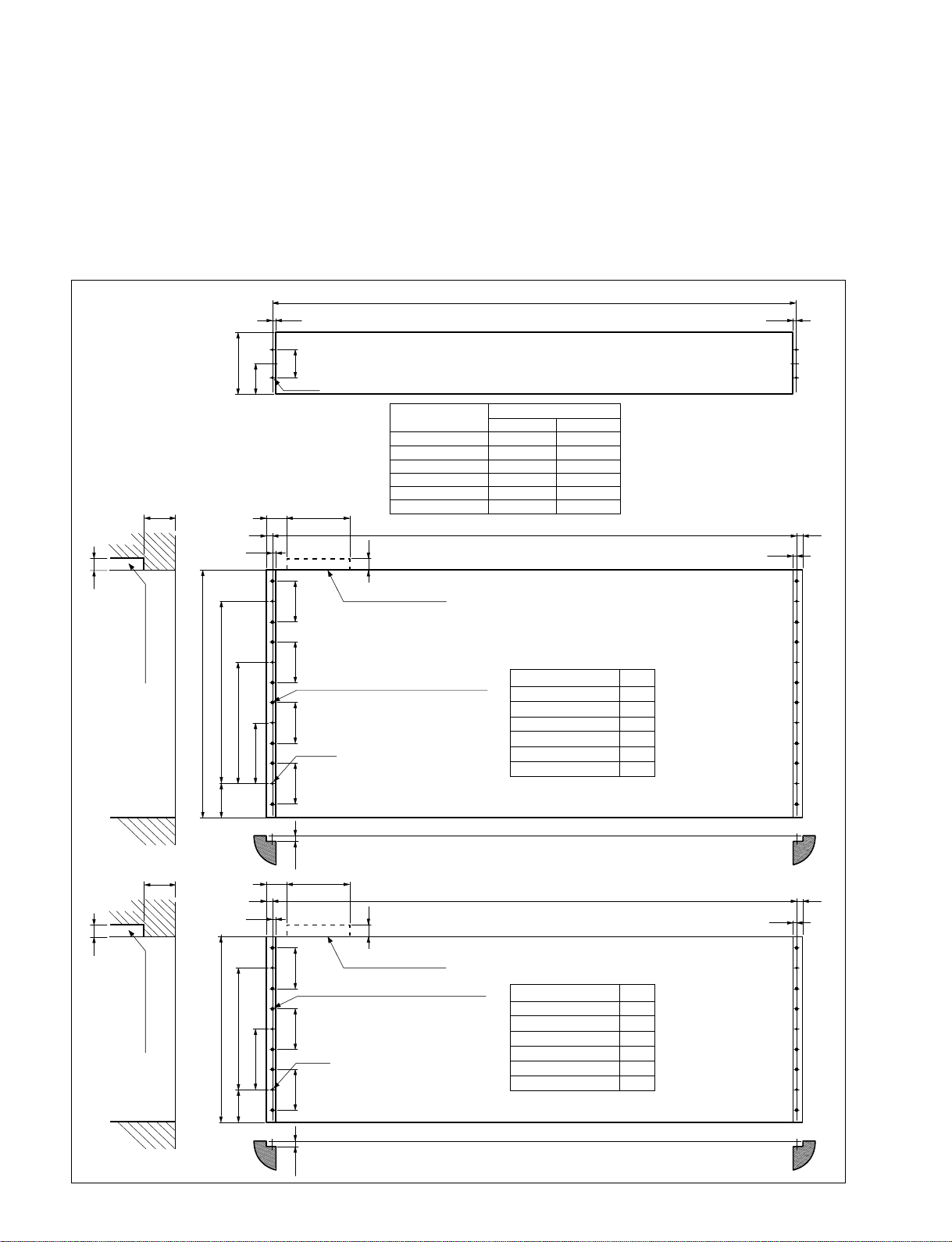
2-4. CCP-8000 Installation
2-4. CCP-8000 Installation
2-4-1. Installation Space
When the main panel or the AUX panel are embedded into a control console or the like, make holes as
shown below into the control console with the following dimensions.
Be sure to have an open space behind the cables of the connectors on the main panel shown as open space
at “A” in the illustrations.
X
5.55.5
20
Bottom
Open space at “A”
134
67
11
5.5
57.2
4-M5
<AUX panel>
3040
100
32XPT SEPARATED
24XPT SEPARATED
16XPT SEPARATED
32XPT INTEGRATED
24XPT INTEGRATED
16XPT INTEGRATED
20
TYPE
SHORT SIZE
765
613
461
765
613
461
X
X
FULL SIZE
1205
1053
901
1425
1273
1121
11
5.5
Open space at “A”
88.988.988.988.911.511.5
<Main panel x 4 lines
(4ME/3ME with built in AUX bus as a signle unit)>
Top
396.467.5
532
264.3
132.1
16-ø5 hole with depth of 3 or more
8-M4
TYPE
32XPT SEPARATED
24XPT SEPARATED
16XPT SEPARATED
32XPT INTEGRATED
24XPT INTEGRATED
16XPT INTEGRATED
X
1205
1053
901
1425
1273
1121
2-6
20
Bottom
Open space at “A”
30
40
Top
11 11
5.5
400
264.3
132.1
67.5
100
20
Open space at “A”
88.988.988.9
12-ø5 hole with depth of 3 or more
6-M4
X
<Main panel x 3 lines
(3ME with AUX bus separate type/2ME)>
TYPE
32XPT SEPARATED
24XPT SEPARATED
16XPT SEPARATED
32XPT INTEGRATED
24XPT INTEGRATED
16XPT INTEGRATED
X
1205
1053
901
1425
1273
1121
5.5
Unit : mm
MVS-8000 System
SYSTEM SETUP
Page 37
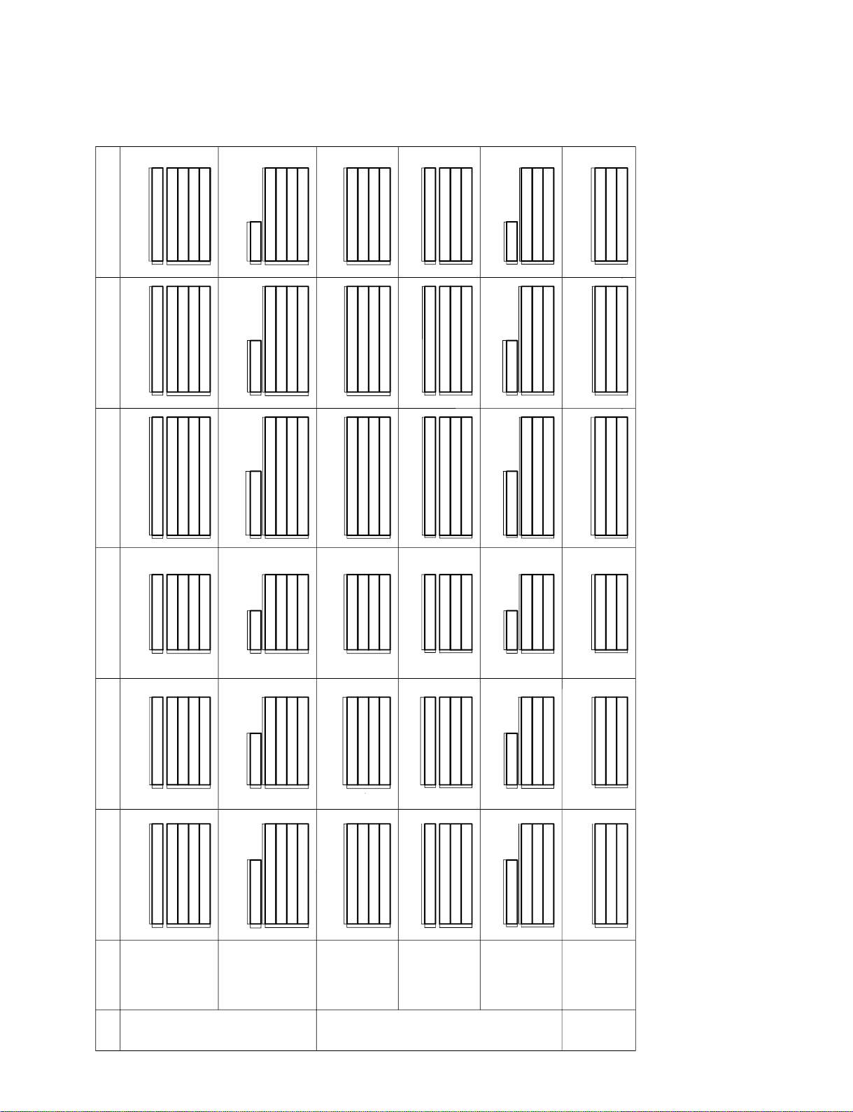
3ME
SIZE
FULL
4ME
2ME
32XPT SEPARATED 24XPT SEPARATED
32XPT INTEGRATED 24XPT INTEGRATED
AUX
SIZE
SHORT
FULL
SIZE
SHORT
SIZE
-IN
BUILT
BUILT
-IN
432SF ASSY 424SF ASSY
432IF ASSY 424IF ASSY
424SO ASSY432SO ASSY
424IO ASSY432IO ASSY
324SB ASSY
324IB ASSY332IB ASSY
332SB ASSY
324IF ASSY332IF ASSY
324SF ASSY
332SO ASSY 324SO ASSY
332IO ASSY 324IO ASSY
232SB ASSY
232IB ASSY 224IB ASSY
224SB ASSY
332SF ASSY
24SO ASSY
ME
316SF ASSY
416SO ASSY
416SF ASSY
216SB ASSY
316SO ASSY
316SB ASSY
16XPT SEPARATED
216IB ASSY
316IO ASSY
316IF ASSY
316IB ASSY
416IO ASSY
16XPT INTEGRATED
416IF ASSY
528
132
1223
528
132
1223
782
528
1223
396
132
1223
782
396
132
1223
396
1223
528
132
1071
528
132
1071
630
528
1071
1071
396
132
132
1071
396
630
396
1071
528
132
1443
528
132
1443
782
1443
528
1443
396
132
396
132
1443
782
396
1443
1291
528
132
528
132
1291
630
528
1291
1291
396
132
396
1291
630
132
396
1291
528
132
919
528
132
478
919
528
919
396
132
919
132
396
478
919
396
919
528
132
1139
528
132
478
1139
528
1139
396
132
1139
396
132
478
1139
396
1139
Main panel/AUX panel configuration list
2-4. CCP-8000 Installation
Unit : mm
MVS-8000 System
SYSTEM SETUP
2-7
Page 38
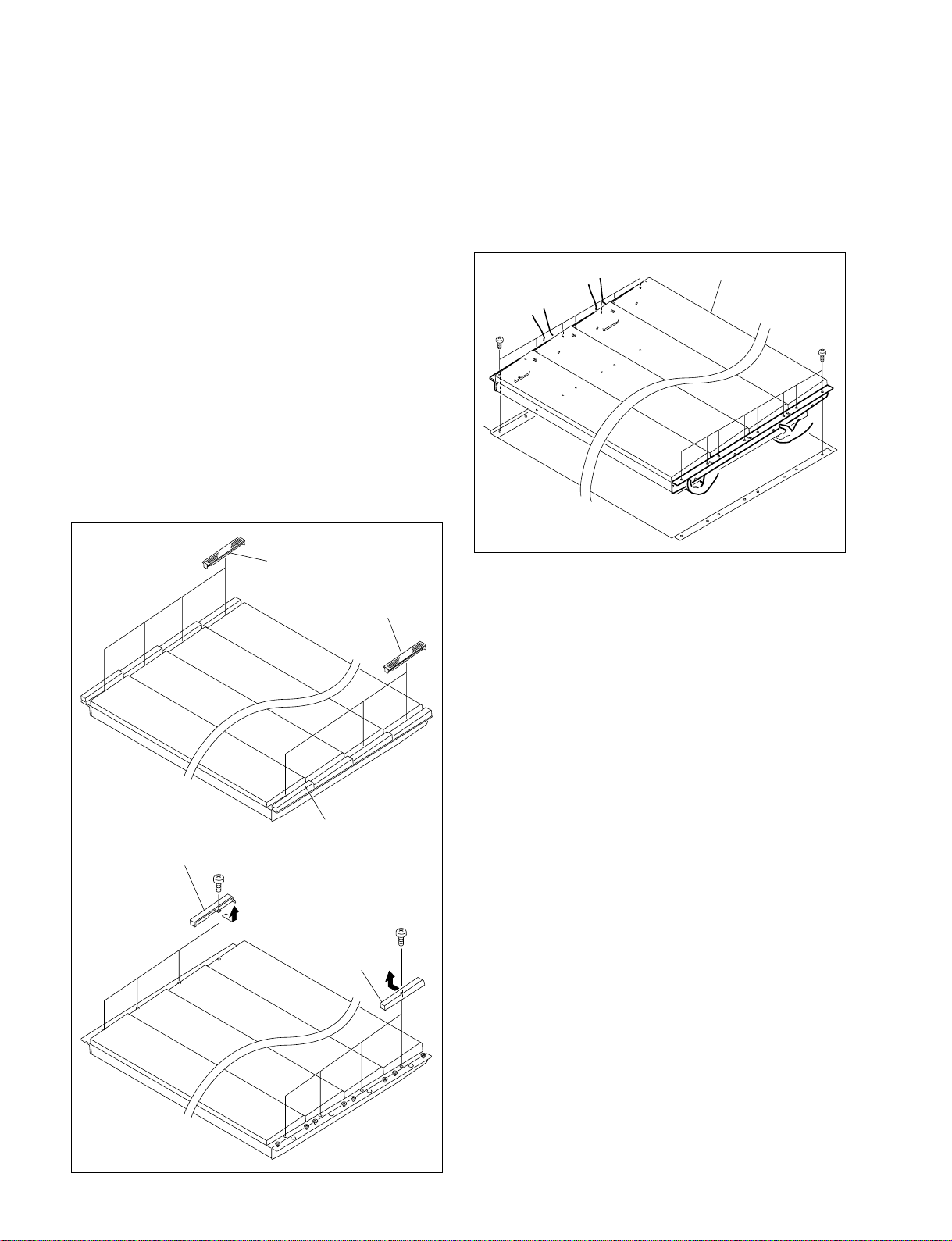
2-4. CCP-8000 Installation
2-4-2. Installing the Main Panel
n
When installing the main panel into the control console, be
sure to install it with three persons or more.
Install the main panel by following the procedure described below.
Tools required
For the 4-line configuration (4ME/3ME with built-in AUX
bus, as a single unit)
Screws (B4 x 6) : 8 pcs
For the 3-line configuration (3ME with AUX bus separate
type/2ME)
Screws (B4 x 6) : 6 pcs
1. Remove the module covers in the right and left.
2. Remove the screws and remove the cap (L) and (R)
respectively.
Module cover
3. Hold the main panel with the two persons or more and
the remaining person installs the main panel into the
control console while holding the main panel.
4. Fix the main panel to the control console with the
screws.
(The illustration below shows the 4-line configuration.)
Main panel
B4 x 6
B4 x 6
Cap (L)
B3 x 6
Cap
Cap (R)
Module cover
B3 x 6
5. Install all of the right and left module covers, and the
caps (L) and (R) by reversing the steps 1 and 2 of
removal.
2-8
MVS-8000 System
SYSTEM SETUP
Page 39
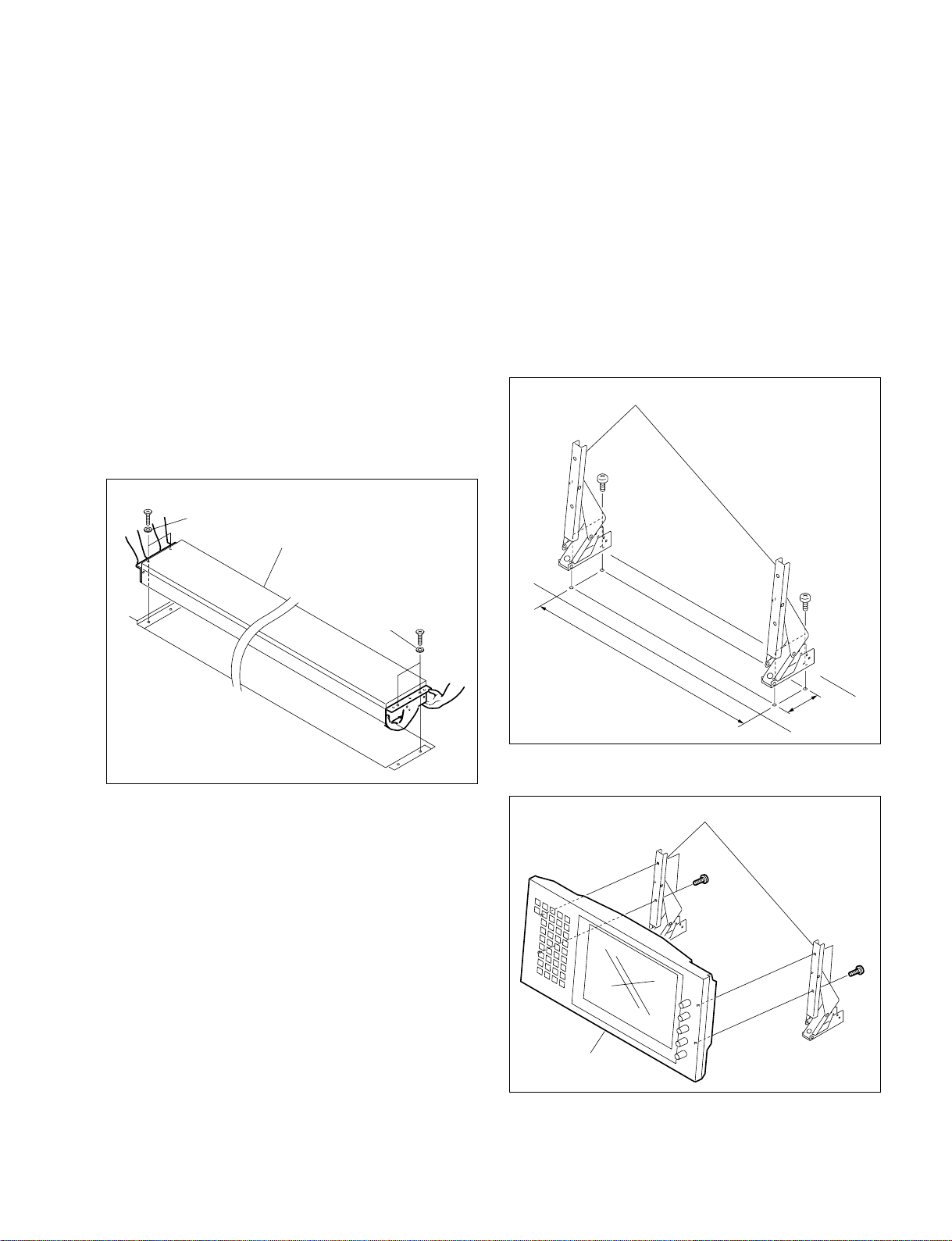
2-4. CCP-8000 Installation
2-4-3. Installing the AUX Panel
n
When installing the AUX panel into the control console, be
sure to install it with two persons or more.
Install the AUX panel by following the procedure described below.
Tools required
. Screws (RK5 x 16) : 4 pcs
. Ornamental washer for rack mount : 4 pcs
(Sony part No. : 2-297-913-01)
1. Hold the AUX panel with the two persons or more and
install the main panel into the control console.
2. Fix the AUX panel to the control console with the
screws.
RK5 x 16
Washer
AUX panel
2-4-4. Installing the Menu Panel
Tools required
. Screws (B4 x 6) : 4 pcs
. Screws (B3 x 5) : 4 pcs
. EL table assemblies :
1. Open the screw holes (M4) as shown in the illustration
into the positions to which the menu panel is going to
be installed.
2. Install the EL table assemblies to the screw holes that
are opened in step 1 using the four screws.
EL table assemblies
B4 x 6
2 pcs (Sony Part No. : X-3167-779-1)
Washer
B4 x 6
RK5 x 16
378 mm
68.5 mm
3. Install the menu panel using the four screws (B3 x 5).
EL table assemblies
B3 x 5
B3 x 5
MVS-8000 System
SYSTEM SETUP
Menu panel
2-9
Page 40
2-4. CCP-8000 Installation
2-4-5. Rack Mounting
Rack Mounting the System Control Unit MKS8010
The MKS-8010 is mounted in the 19-inch standard rack.
To mount the MKS-8010 in the rack, use the specified rack
mount kit and follow the procedure described below.
Specified rack mount kit : RMM-10
n
If a rack mount kit other than the specified one is used, the
unit may not be mounted in the 19-inch standard rack.
Parts of the RMM-10
. Rack tools 2 pcs
. Right rack mount adaptor 1 pc
. Left rack mount adaptor 1 pc
. Rack tool attaching screws 6 pcs
(B4 x 6 : 7-682-560-09)
. Rack tool attaching screws 6 pcs
(B4 x 10 : 7-682-560-10)
2. Rack mounting procedure
This section describes the rack mounting procedure using
the RMM-10 rack mount kit.
n
Tighten the screws to the following torque.
Tightening torque : 120 x 10_2 N.m {12.2 kgf.cm}
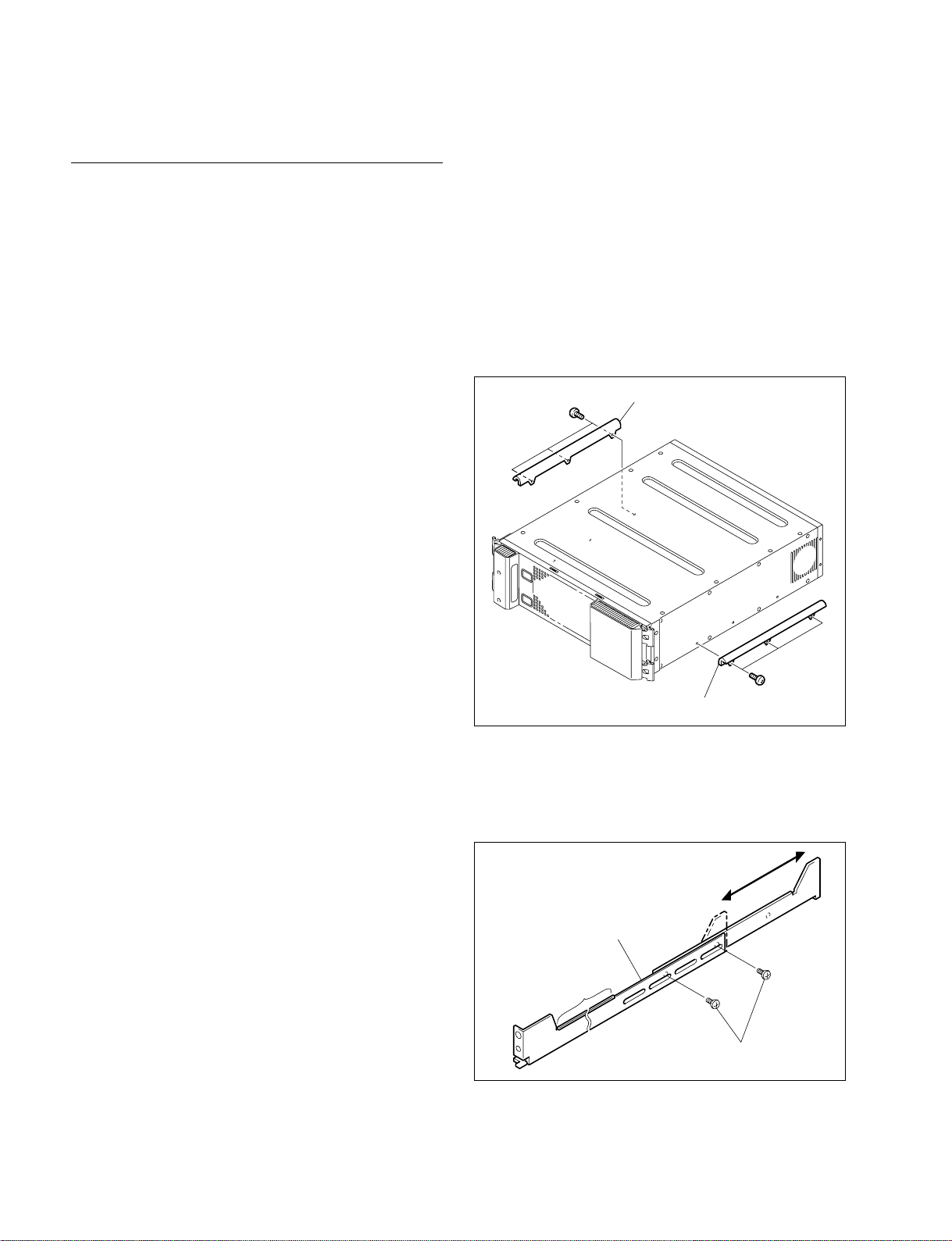
1. Attach the rack tool to the side of the equipment using
the specified six screws.
n
Use B4 x 6 screws.
B4 x 6
Rack tool
1. Precautions for rack mounting
w
. To prevent the rack from falling or moving, fix the rack
on a flat and steady floor using bolt or others.
If the rack falls due to the weight of the equipment, it
may cause death or injury.
. Be sure to use the specified rack mount kit.
If not, injury may result and the equipment may fall due
to insufficient strength.
. After rack mounting, be sure to tighten the screws on the
rack angle and fix the unit in the rack.
If the screws on the rack angle are not tightened, the unit
may slip from the rack and fall, causing injury.
c
When mounting the unit in the rack, note the following:
. Be sure to mount in the rack with two persons or more.
. Be careful not to catch your fingers or hands in the rack
mount rail or others.
. Mount in the rack in a stable position.
n
If several units are mounted in a rack, it is recommended to
install a ventilation fan to prevent temperature rise inside
the rack.
Rack tool
B4 x 6
2. Loosen the screws on the rear of the right and left
adaptors and adjust the length of the adaptor according
to the depth of the rack.
(The illustration below shows the left adaptor.)
Adaptor
Portion of the rail
B4 x 6
n
Maximum depth of adaptor : 750 mm
Minimum depth of adaptor : 595 mm
2-10
MVS-8000 System
SYSTEM SETUP
Page 41
2-4. CCP-8000 Installation
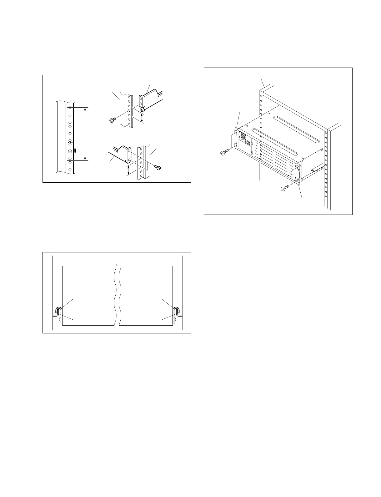
3. Attach the right and left adaptors to the rack completely using the specified six screws.
(The illustration below shows the left adaptor.)
Adaptor
Rack
B4 x 10
3U
Adaptor
31.75
31.75
Rack
B4 x 10
Unit : mm
4. Tighten the screws (B4 x 6 : two screws each on the
right and left) for adjusting the length of the adaptor
completely (the screws that were loosened in step 2).
5. Align the groove of the rack tool at the side of the equipment with the rail, and slide the equipment to the rear.
n
The rack tools are hooked on the rails as shown below.
7. Fix the rack angle in the rack using the specified
screws.
Rack
Rack angle
B5 x 12
B5 x 12
Rack angle
8. Attach the front panel to the equipment.
Rack tool
Rail Rail
Rack tool
6. Remove the front panel. (Refer to Section 2-1.)
MVS-8000 System
SYSTEM SETUP
2-11
Page 42
2-4. CCP-8000 Installation
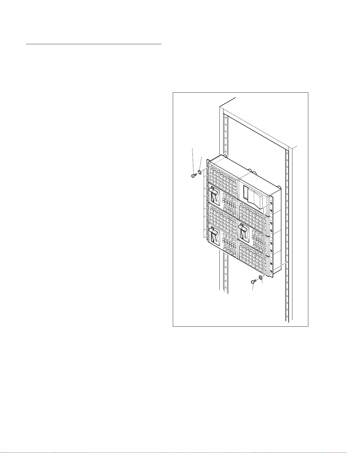
Rack Mounting the MKS-8075 (Extension
Adaptor)/MKS-8076 (Memory Card/USB Adaptor)
The MKS-8075 and MKS-8076 can be mounted in the 19inch standard rack.
To mount them in the rack, use the recommended rack
mount parts and follow the procedure described below.
n
In order to rack mount the MKS-8075 and MKS-8076, the
following conditions must be met.
. The two or more adaptors must be configured to the two
rows as shown in the illustration by connecting them
horizontally together.
. Number of adaptors connected must be either 2 or 4 or 6
or 8.
. The connection method C (flat) must be used.
. For the connection method, refer to “2-8-1. Connecting
the MKS-8075/MKS-8076”.
Tools required
. Screws (RK5 x 16) for rack mounting
. Ornamental washer for rack mount
(Sony part No.: 2-297-913-01)
When 2 adaptors are connected : Each 4 pcs
When 4 adaptors are connected : Each 8 pcs
When 6 adaptors are connected : Each 12 pcs
When 8 adaptors are connected : Each 16 pcs
2. Rack mounting procedure
(1) Install the adaptor to the rack using rack mounting
screws (RK5 x 16) and washers as shown in the
illustration.
(The illustration below shows the configuration when
8 adaptors are connected.)
RK5 x 16
Washer
1. Precautions for rack mounting
w
. To prevent the rack from falling or moving, fix the rack
on a flat and steady floor using bolt or others.
If the rack falls due to the weight of the equipment, it
may cause death or injury.
. Be sure to use the side panels of the adaptor itself for
rack mount.
If not, injury may result and the equipment may fall due
to insufficient strength.
. After rack mounting, be sure to tighten the screws on the
side panels and fix the unit in the rack.
c
When mounting the unit in the rack, note the following:
. Be sure to mount in the rack with two persons or more.
. Mount in the rack in a stable position.
Washer
RK5 x 16
2-12
MVS-8000 System
SYSTEM SETUP
Page 43

2-5. DCU-8000 Installation
2-5. DCU-8000 Installation
2-5-1. Rack Mounting
The DCU-8000 can be mounted in the 19-inch standard
rack.
To mount the DCU-8000 in the rack, use the specified rack
mount kit and follow the procedure described below.
Specified rack mount kit : RMM-10
n
If a rack mount kit other than the specified one is used, the
unit may not be mounted in the 19-inch standard rack.
Parts of the RMM-10
. Rack tools 2 pcs
. Right rack mount adaptor 1 pc
. Left rack mount adaptor 1 pc
. Rack tool attaching screws 6 pcs
(B4 x 6 : 7-682-560-09)
. Rack tool attaching screws 6 pcs
(B4 x 10 : 7-682-560-10)
2. Rack mounting procedure
This section describes the rack mounting procedure using
the RMM-10 rack mount kit.
n
Tighten the screws to the following torque.
Tightening torque : 120 x 10_2 N.m {12.2 kgf.cm}
1. Attach the rack tool to the side of the equipment using
the specified six screws.
n
Use B4 x 6 screws.
Rack tools
B4 x 6
1. Precautions for rack mounting
w
. To prevent the rack from falling or moving, fix the rack
on a flat and steady floor using bolt or others.
If the rack falls due to the weight of the equipment, it
may cause death or injury.
. Be sure to use the specified rack mount kit.
If not, injury may result and the equipment may fall due
to insufficient strength.
. After rack mounting, be sure to tighten the screws on the
rack angle and fix the unit in the rack.
If the screws on the rack angle are not tightened, the unit
may slip from the rack and fall, causing injury.
c
When mounting the unit in the rack, note the following:
. Be sure to mount in the rack with two persons or more.
. Be careful not to catch your fingers or hands in the rack
mount rail or others.
. Mount in the rack in a stable position.
n
If several units are mounted in a rack, it is recommended to
install a ventilation fan to prevent temperature rise inside
the rack.
B4 x 6
Rack tools
2. Loosen the screws on the rear of the right and left
adaptors and adjust the length of the adaptor according
to the depth of the rack.
(The illustration below shows the left adaptor.)
Adaptor
Portion of
the rail
B4 x 6
n
Maximum depth of adaptor :750 mm
Minimum depth of adaptor : 595 mm
MVS-8000 System
SYSTEM SETUP
2-13
Page 44
2-5. DCU-8000 Installation
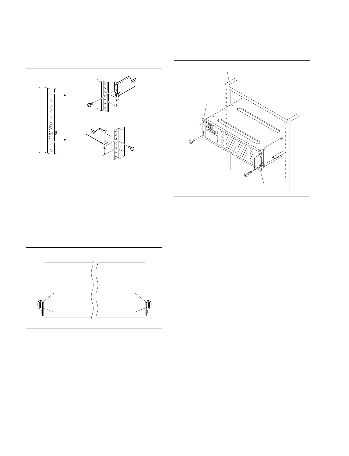
3. Attach the right and left adaptors to the rack completely using the specified six screws.
(The illustration below shows the left adaptor.)
B4 x 10
3U
31.75
31.75
B4 x 10
Unit : mm
4. Tighten the screws (B4 x 6 : two screws each on the
right and left) for adjusting the length of the adaptor
completely (the screws that were loosened in step 2).
5. Align the groove of the rack tool at the side of the
equipment with the rail, and slide the equipment to the
rear.
n
The rack tools are hooked on the rails as shown below.
7. Fix the rack angle in the rack using the specified
screws.
Rack
Rack angle
B5 x 12
B5 x 12
Rack angle
8. Attach the front panel to the equipment.
Rack tool
Rail Rail
Rack tool
6. Remove the front panel. (Refer to Section 1-4-1)
2-14
MVS-8000 System
SYSTEM SETUP
Page 45

2-6. MVS-8000 system video Cabling
2-6. MVS-8000 System Video Cabling
The MVS-8000 system connections is shown in the illustration.
Different video and control wiring configurations may be created to meet individual facility requirements.
Each input can be assigned to any CCP panel source select button, and any MVS system video signal can
be assigned to any pair of output connectors.
MVS-8000 system video cabling
DME Processor Pack
MVE-8000
SWITCHER ASWITCHER B
Camera
VTR
Routing Switcher
MONITOR
5
DME 1B
PRIMARY INPUTS
1 to 68
8
PRIMARY INPUTS
69 to 80
MONITOR OUTPUTS
8
1 to 8
Reference video
signal (*3)
Reference video signal (*3)
Switcher Processor Pack
MVS-8400/8300/8200
AC100 to 240 V Power Supply (*1)
DME 1A
OUTPUTS 1 to 48
75-pin Cable
5
AC100 to 240 V Power Supply (*2)
AC100 to 240 V Power Supply (*2)
MONITOR
8
VTR
AC100 to 240 V Power Supply (*2)
AC100 to 240 V Power Supply (*2)
Video Signal Input
8
Video Signal Output
Video/Key Signal
5
AC Power Supply
(*1) : For the AC power cord, refer to “Optional Items” of the “DME Processor Pack MVE-8000” Operation Manual.
(*2) : For the AC power cord, refer to “Optional Items” of the “Multi-Format Switcher Processor MVS-8000”
Operation Manual.
(*3) : Terminate the system with the 75 Z terminator supplied with this unit.
Supplied and required cables
Cable Description Quantity Part No.
DME V/K Interface MDR 68-pin Female 2 Supplied with MVE-8000
MVS-8000 System
SYSTEM SETUP
2-15
Page 46
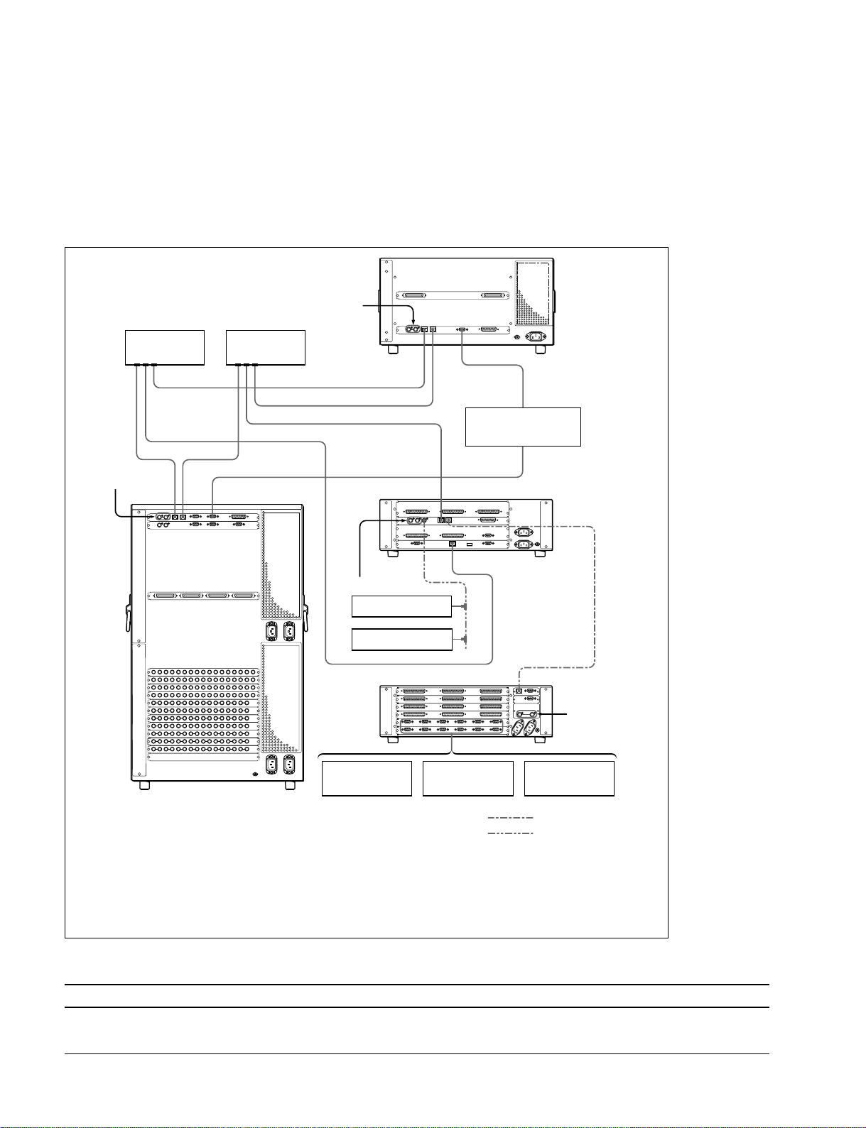
2-7. MVS-8000 System Control Cabling
2-7. MVS-8000 System Control Cabling
2-7-1. Cabling
The MVS system uses Ethernet, serial, parallel, USB and S-BUS control. Tally and GPI control are also
available from DCU-8000 and CCP-8000 (System Control Unit).
MVS-8000 system control cabling
Reference video signal (*2)
Ethernet switch
Reference video
signal (*2)
DATA CTRL REMOTE 1
(*1)
Ethernet switch
(*1)
DATA LAN
REMOTE
Reference video
signal (*2)
BKS-R series
HDS-X series
Device Control Unit Pack DCU-8000
CTRL
EDITOR
Editing Control System
CTRL
DATA
DME Processor Pack
MVE-8000
BVE-9100
PERIPH
System Control Unit
MKS-8010
PERIPH
Reference video
signal (*2)
Audio mixer
Crossover cable
BNC cable
Switcher Processor Pack
MVS-8400/8300/8200
VTR DDR
(*1) : Connect each LAN (CTRL, DATA) to the separate Ethernet switches respectively.
However, a single Ethernet switch can be used for connecting each LAN.
For information about Ethernet switches that can be used in an MVS system, refer to “2-7-2. LAN
Requirements” and “3-4. Ethernet Switch Settings”.
For detailed information about setting up the Ethernet switch, refer to the documentation -supplied with the switch.
(*2) : Terminate the system with the 75 Z terminator supplied. The 75 Z terminator is supplied with the equipment.
Supplied and required cables
Cable Description Quantity Part No.
LAN cable RJ-45 *_
Conforms to the IEEE802.3
Ethernet 100 BASE-TX
* : Quantity depends on the configuration.
2-16
MVS-8000 System
SYSTEM SETUP
Page 47
Control cable length
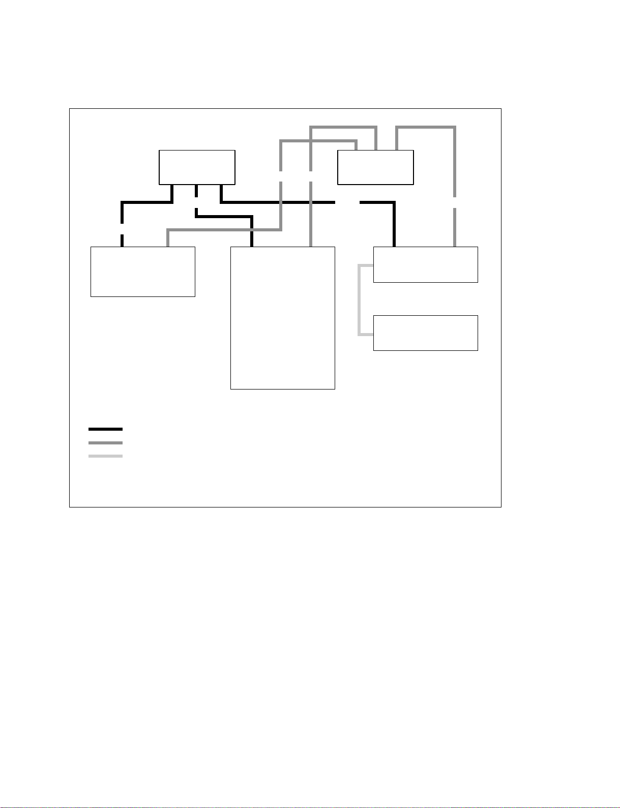
One Ethernet cable is available up to 100m from an Ethernet switch.
2-7. MVS-8000 System Control Cabling
Ethernet Switch Ethernet Switch
100 m100 m
100 m
100 m
MVE-8000 MVS-8000
Control LAN is 100 BASE-TX Ethernet
Data LAN is 100 BASE-TX Ethernet
Peripheral LAN is 100 BASE-TX Ethernet.
A direct DCU-8000-to-MKS-8010 connection requires a cross cable.
A direct Peripheral LAN connection does not require an Ethernet switch.
100 m100 m
MKS-8010
DCU-8000
MVS-8000 System
SYSTEM SETUP
2-17
Page 48

2-7. MVS-8000 System Control Cabling
2-7-2. LAN Requirements
The MVS-8000 system requires an Ethernet Local Area Network (LAN) for System Control LAN and
Data LAN.
Switcher Processor (MVS-8000), DME Processor (MKS-8800), and System Control Unit (MKS-8010)
are all connected via an Ethernet switch of appropriate specification.
Data LAN requires separate Ethernet switch from the one for Control LAN to avoid delay of the processing.
m
. Ethernet Hubs are not acceptable for the MVS-8000 system Ethernet connection.
Use of hub instead of a switch may cause sluggish responses to panel button.
Connect each LAN (Control/Data) nodes to the different switch to avoid sluggish.
. Ethernet switches are not supplied with MVS-8000 system.
Ethernet specification
Refer to Table below for a list of required Ethernet Specifications for MVS-8000 system.
Ethernet specification
Cable Type 100 BASE-TX compatible.
Connectors RJ-45 male connector at each end of cable
Length 100 m maximum
Switch Capacity of backbone Higher than 1.5 Gbps
Throughput Higher than 120 Kbps (a port) packet size 64 Byte
Delay time of packet Less than 50u sec
Speed Dual : 100 Mbps
Ports RJ-45 auto negotiating 100 Mbps
VALN Compatible
Switching mode Store-and-Forward
Management SNMP, RMON
Total throughput : higher than 3 Mbps
Number of ports required is dependent upon system configuration
2-18
MVS-8000 System
SYSTEM SETUP
Page 49
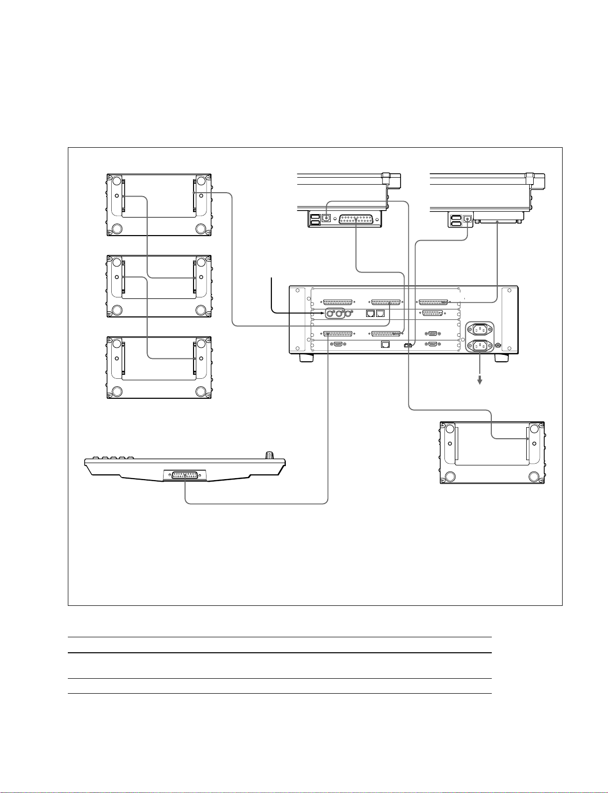
2-8. CCP-8000 Panel Cabling
CCP-8000 panel modules connections are shown in figure.
CCP-8000 system control cabling
2-8. CCP-8000 Panel Cabling
Extension Adaptor MKS-8075
SCU OUT
SCU IN
(Max.10 m)
SCU OUT
SCU IN
(Max.10 m)
IN
Reference video signal
(Max.10 m)
EXT PANEL 2
System Control Unit
MKS-8010
Main panel
MENU PANEL
AUX panel
HOST
SCU
(Max.5 m)
(Max.5 m)
(Max.5 m)
MAIN PANEL EXT PANEL3
DEVICE
DEVICE
(Max.5 m)
(Max.10 m)
(*1)
AC 100 to 240 V
SCUHOST
HOST
Menu Panel
MKS-8011
SCU
(Max.5 m)
Memory Card/USB Adaptor
(*1) : There are three methods as described below to install the memory card/USB module MKS-8025.
. In order to install the memory card/USB adaptor MKS-8025 into the main panel, connect the DEVICE terminal of the
MKS-8010 to the HOST terminal of the main panel.
. In order to install the memory card/USB adaptor MKS-8025 into the AUX panel, connect the DEVICE terminal of the
MKS-8010 to the HOST terminal of the AUX panel.
. In order to install the memory card/USB adaptor MKS-8025 outside the system using the MKS-8076, connect the
DEVICE terminal of the MKS-8010 to the HOST terminal of the MKS-8076.
Supplied and required cables
Cable Description Quantity Part No.
EXT/MENU/MAIN D-sub 50-pin cable (5/10 m) * Supplied with CCP-8000
PANEL cable SWC-5005/SWC-5010
USB cable USB Type A 1 Supplied with CCP-8000
* : Quantity depends on the configuration.
MVS-8000 System
SYSTEM SETUP
MKS-8076
2-19
Page 50

2-8. CCP-8000 Panel Cabling
Panel cable length
System Control Unit
5 m
MKS-8010
10 m
5 m
5 m
Menu Panel
AUX Panel (separate)
MKS-8076
MKS-8075
5 m
10 m
Main Panel
MKS-8075
10 m
MKS-8075
10 m
Max. 30m
MKS-8075
10 m
MKS-8075
10 m
MKS-8075
10 m
MKS-8075
2-20
10 m
MKS-8075
Menu Panel, EXT panel connections are a D-Sub 50pin.
EXT panel connection is a D-Sub 50pin.
Memory Card/USB (with MKS-8076) is USB Type A connection.
MVS-8000 System
SYSTEM SETUP
Page 51

2-8. CCP-8000 Panel Cabling
n
The maximum number of modules that can be connected to a single MKS-8010 System Control Unit is as
follows.
The maximum number of adaptors that can be connected on 1 line is 8 units.)
Model Model Name Max modules
MKS-8013/8014/8015 32, 24, 16 AUX BUS MODULE 2
MKS-8026 10 KEY PAD MODULE 1
MKS-8030 KEY FRAME MODULE 1
MKS-8031TB TRACK BALL MODULE 1
MKS-8031JS JOY STICK MODULE 1
MKS-8035 KEY CONTROL MODULE 4
MKS-8023 COMPACT KEY TRANSITION MODULE 4
MKS-8032 DSK FADER MODULE 4
MKS-8033 UTILITY/SHOTBOX MODULE 2
However, it is not possible to connect four Key Control modules and a 10 Key Pad module on one line.
You can also connect keyboards, mouse, pen tablets and other devices with USB connectors regardless of
whether an MKS-8025 has been installed in the main panel or installed apart form the main panel using
an MKS-8076 adaptor.
MVS-8000 System
SYSTEM SETUP
2-21
Page 52
2-8. CCP-8000 Panel Cabling
2-8-1. Connecting the MKS-8075/MKS-8076
Structure of MKS-8075
(Connecting the extension adaptor)
Adaptor case : 1
Screw (BV3 x 10) : 4
Connecting plate A : 1
Connecting plate B : 1
Connecting plate C : 2
Panel cover (L) : 1
Panel cover (R) : 1
Cable (D-sub 50-pin): 1
Structure of MKS-8076 (Memory card/USB adaptor)
Adaptor case : 1
Screw (BV3 x 10) : 4
Connecting plate A : 1
Connecting plate B : 1
Connecting plate C : 2
Panel cover (L) : 1
Panel cover (R) : 1
How to Connect the MKS-8075 and the MKS-8076
m
.
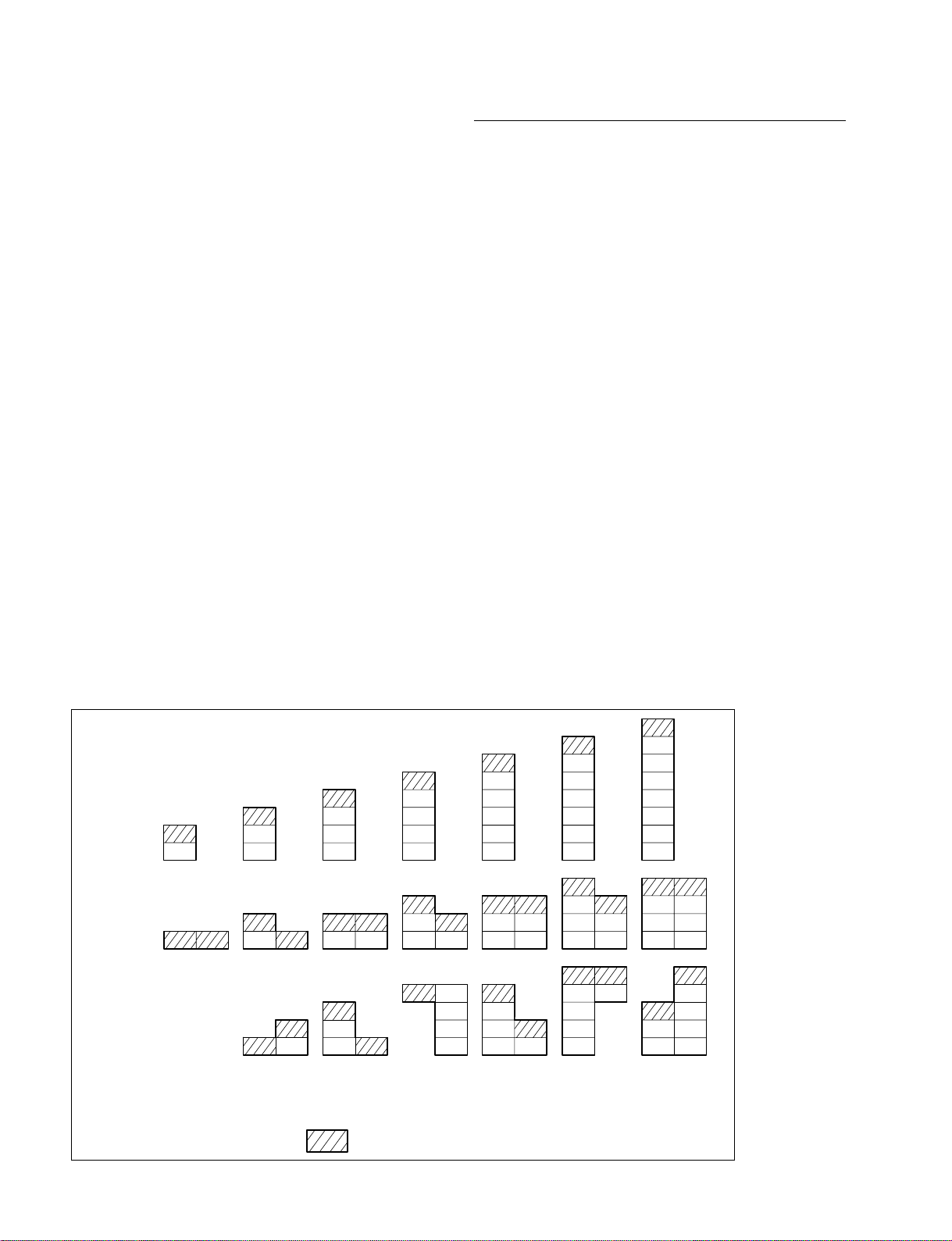
A maximum of eight extension adaptors can be connected by
using the horizontal connection and the vertical connection.
(The horizontal connection can be configured up to the
two horizontal connection line at the maximum.)
(For an example of connection, refer to Fig. 1.)
. There are three methods of vertical connection as
described below. (Refer to Fig. 2. (2-25 page))
Method A : Install the extension adaptors on the panel so
that they have differences in height like
flight of steps having the same outside
appearance as that of the main panel.
Method B : Install the extension adaptors flat on the
panel without any differences in height.
(In such a case as installed on tabletop)
Method C : Install the extension adaptors in the rack.
(Horizontal connection is also required.)
. When the extension adaptors are installed using both of
the horizontal and vertical connections, be sure to
perform the vertical connection first then perform the
horizontal connection.
. When the MKS-8076 is going to be installed, install it in
the top-most position. (Refer to Fig. 1.)
. When the vertical connection (A) is selected, be sure to
secure all of the side panels with screws. Never panel it
on table top. (The fixing method is same as that of the
main panel.)
Fig. 1 : Example of connection method
Number of
connections
2345678
2-22
: The position where the MKS-8076 can be connected
MVS-8000 System
SYSTEM SETUP
Page 53
2-8. CCP-8000 Panel Cabling
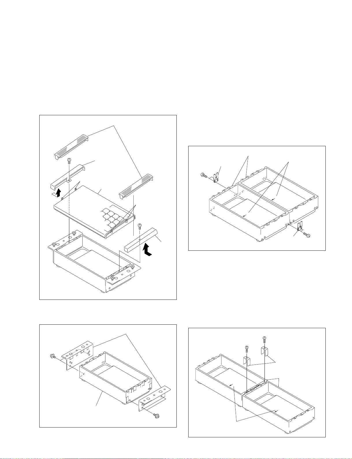
Connecting procedure
1. Remove the module cover. Remove the screws (BV3
x 10) fixing the caps (L) and (R), and remove the caps
in the direction of the arrow.
2. Loosen the four screws (with drop-safe) fixing the
operation module.
3. Hold the two screws (with drop-safe) in the front of
the both sides of the operation module, and remove the
operation module.
Module covers
Cap (L)
BV3 x 10
Screws
(with drop-safe)
Operation module
Screws
(with drop-safe)
BV3 x 10
When the Vertical connection is selected
(1)
Connect the adaptor cases that you want to connect, together.
(Be careful of the direction of the adaptor cases. See the
instruction given on the bottom of the adaptor case.)
Fix the right and left of the adaptor cases as shown in the
(2)
illustration using the two pieces of the connecting plate C.
.
When fixing the adaptor cases, you can select either the
flat connection or the connection like flight of steps.
. When selecting the connection like flight of steps of
the connection method (A), (see Fig. 2) the two
screws are secured with one notch offset each other.
. When the flat connection of the connection method
(B, C) is selected, (see Fig. 2) the two screws are
secured in the same height.
BV 3 x 10
Connecting
plate C
Adaptor cases
F
R
O
N
T
Instruction given on
the bottom of the case
F
R
O
N
T
Cap (R)
4. Remove the screws (BV3 x 10) fixing the side plates
to the adaptor case, and remove the side plates.
Side plates
BV3 x 10
Adaptor case
Connecting
plate C
BV 3 x 10
When the Horizontal connection is selected
(1) Connect the adaptor cases that you want to connect,
together.
(Be careful of the direction of the adaptor cases. See the
instruction given on the bottom of the adaptor case.)
(2) Fix the top plate of the adaptor cases at the locations
shown in the illustration using the two connecting
screws and the two pieces of the connecting plate A
for every two pieces of adaptor case.
BV3 x 10
BV3 x 10
Connecting plates A
Adaptor cases
FRONT
FRONT
MVS-8000 System
SYSTEM SETUP
BV3 x 10
Instruction given on the
bottom of the cases
2-23
Page 54
2-8. CCP-8000 Panel Cabling
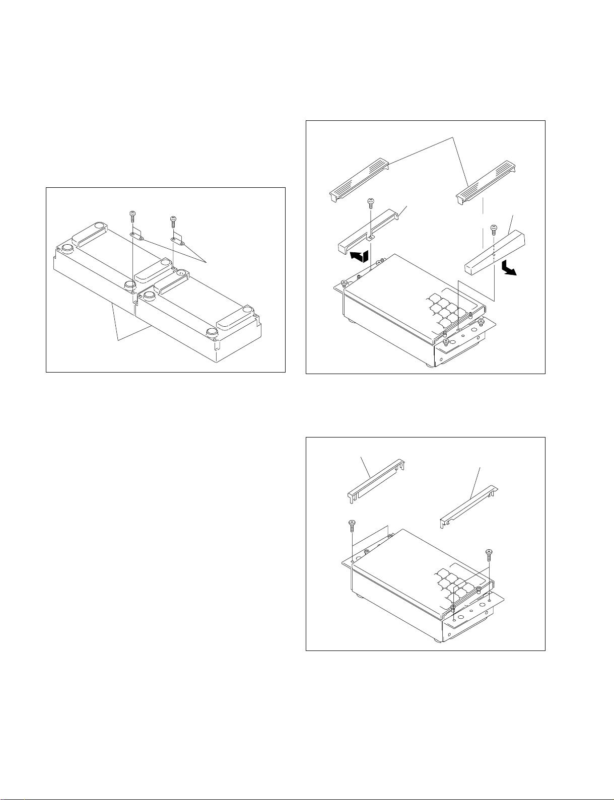
(3) Fix the bottom plate of the adaptor cases at the loca-
tions shown in the illustration using the 4 connecting
screws (BV3 x 10) and the 2 pieces of the connecting
plate B for every 2 pieces of adaptor case.
n
When the Vertical connection (A) is selected, there are
several locations where the connecting plate B cannot
be fixed. It makes no problems.
BV3 x 10
Adaptor cases
BV3 x 10
Connecting plate B
7. For the connection methods (A) and (B) (see Fig. 2),
install the caps (L) and (R), and the module cover in
the direction of the arrow.
Module covers
BV3 x 10
Cap (L)
Cap (R)
BV3 x 10
5. Install the side panel.
n
The screw positions that fix the side panel are different
in the connection methods (A), (B) and (C) respectively. (see Fig. 2)
6. Install the operation module and fix it by tightening
the four screws on the sides.
For the connection method (C) (see Fig. 2), remove the
four stepped screws and install the panel covers (L)
and (R).
Panel cover (L)
Panel cover (R)
Stepped screws M3
Stepped screws M3
2-24
MVS-8000 System
SYSTEM SETUP
Page 55
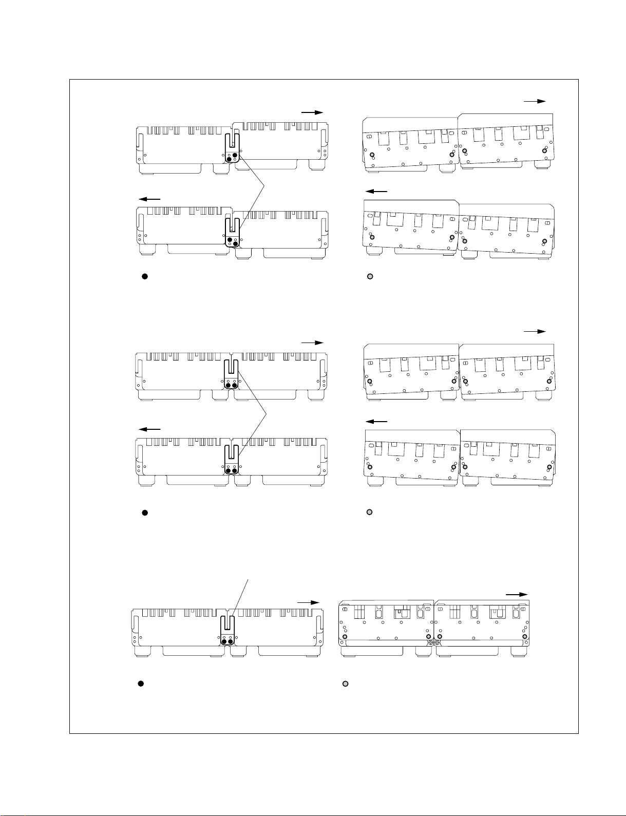
Fig. 2 : Side panel installation methods
Left side
2-8. CCP-8000 Panel Cabling
FRONT
FRONT
Right side
Left side
Right side
FRONT
FRONT
Connecting plate C
Connection method (A)
FRONT
Connecting plate C
FRONT
: Side plate screw fixing position: Connecting plate screw fixing position
FRONT
FRONT
MVS-8000 System
SYSTEM SETUP
: Connecting plate screw fixing position
Left side
(Same as the right side)
: Connecting plate screw fixing position
Connection method (B)
Connecting plate C
FRONT
Connection method (C)
: Screw fixing position
FRONT
: Screw fixing position
2-25
Page 56
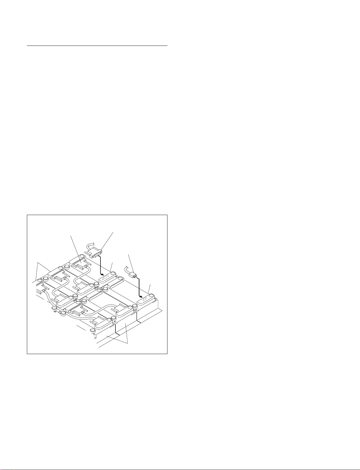
2-8. CCP-8000 Panel Cabling
How to Connect the Cables
Parts required
. 50-pin cable supplied with the center control panel
. 50-pin cable supplied with the MKS-8075
. USB cable (5 m) supplied with the center control panel
Connecting cables for the MKS-8075
1. Connect the EXT PANEL 1 to 3 terminals of the
system control unit MKS-8010 to the SCU IN terminals of the MKS-8075 using the 50-pin cable supplied
with the center control panel.
2. Connect the SCU OUT terminal of the MKS-8075 to
the SCU IN terminal of the adjacent MKS-8075 using
the cable supplied with the MKS-8075 as shown in the
illustration.
Connecting cables for the MKS-8076
Connect the DEVICE terminal of the system control unit
MKS-8010 to the IN terminal of the MKS-8076 using the
USB cable supplied with the center control panel.
50-pin cable supplied
with the MKS-8025
MKS-8075
T
U
O
T
U
O
IN
50-pin cable supplied with
the center control panel
USB cable supplied with
the center control panel
T
U
O
IN
T
U
O
T
U
O
MKS-8075
IN
O
IN
T
U
IN
MKS-8076
IN
MKS-8075
2-26
MVS-8000 System
SYSTEM SETUP
Page 57

Section 3
Configuration
3-1. Introduction
This section provides system configuration information for the MVS-8000 system
The MVS-8000 system has three Ethernet connections for panel and devices communications (control,
data, peripheral systems).
The control LAN is intended to control the various devices from the center control panel (CCP-8000).
The data LAN is intended to exchange of various type of data (key frame effects, snapshot, etc.) and still
pictures of frame memory. This network allows the transfer of files without adversely effecting communications over the control LAN.
The peripheral LAN is intended to exchange tally information between the center control panel and the
device control unit.
All MVS-8000 system devices on same LAN must be connected to the same Ethernet switch.
n
It is not available to connect MVS-8000 system LAN to your existing facility LAN.
The control LAN and peripheral LAN allow the following number of devices within a LAN to keep realtime processing.
Number of devices on a Control LAN
Device Quantity
Switcher processor 2
DME processor 4
Center control panel 4
Total 10
Number of devices on a Peripheral LAN
Device Quantity
Center control panel 4
Device control unit 2
Total 6
3-2. Basic Configuration Steps
Basically, the following steps need to complete system configuration.
1. Set IP address.
2. Configure Ethernet switch.
3. Power up system.
MVS-8000 System
SYSTEM SETUP
3-1
Page 58

3-3. IP Address
3-3. IP Address
The MVS-8000 system uses IP address 10.x.x.x.
Each device of MVS-8000 system has independent NETWORK terminal for each LAN.
The IP address for all NETWORK terminals has same rules as below.
The IP address is identified by four byte of the form below.
10.AA.BB.CC
ex. 10.1.2.1
10. AA. BB. CC.
Fixed GROUP ID + LAN ID Unit cord (Fixed) Unit ID
GROUP ID is defined as DIP It uses to identify unit category. Unit ID is defined as DIP SW of
SW of GROUP ID 1 to 63. UNIT ID 1 to 254.
LAN IDs are as follows ;
Control LAN : 0
Peripheral LAN : 64
Data LAN : 128
Used bit for LAN Group ; Unit category are as follows ; Used bit ;
Control LAN : 1 to 63 PANEL : 1 1 to 254
Peripheral LAN : 65 to 127 SWITCHER : 2
Data LAN : 129 to 191 DME : 3
PFV-SP : 4
DCU : 5
ROUTER : 6
*1 : the default setting is “1”.
*1
Host name
When IP address is defined, it is also named host name automatically.
The host name is identified by ten digits (characters and numbers) of the format below.
Format :
Unit name (3 characters) + Group ID (3 digits) + LAN code (1 character) + Unit ID (3 digits)
Example :
IP address : 10.1.1.1 Host name : PNL001C001
Unit category Unit name
PANEL PNL
SWITCHER SWR
DME DME
DCU DCU
Group ID + LAN Code
Control LAN 001C to 063C
Peripheral LAN 001P to 063P
Data LAN 001D to 063D
3-2
MVS-8000 System
SYSTEM SETUP
Page 59
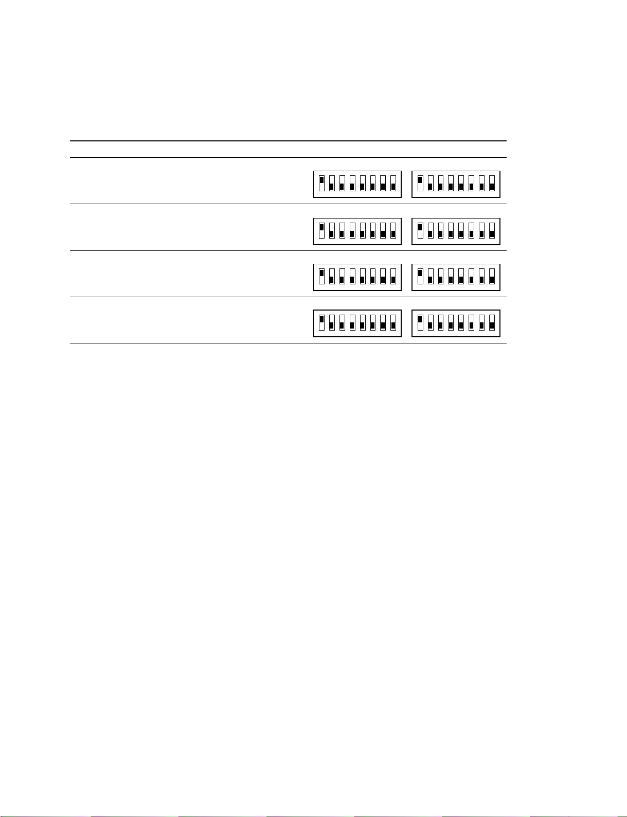
3-3-1. Default IP Address
The MVS-8000 system is shipped with default IP addresses. Sony Corporation has chosen these default
IP addresses to make MVS-8000 system configuration easy.
Device IP Address Host name Dipswitch setting
MVS-8000 10.1.2.1 (C) SWR001C001
10.129.2.1 (D) SWR001D001
Group ID
12345678
Unit ID
12345678
3-3. IP Address
MVE-8000 10.1.3.1 (C) DME001C001
Group ID
Unit ID
10.129.3.1 (D) DME001D001
CCP-8000 10.1.1.1 (C) PNL001C001
12345678
Group ID
12345678
Unit ID
10.65.1.1 (P) PNL001P001
10.129.1.1(D) PNL001D001
DCU-8000 10.65.5.1 (P) DCU001P001
C : Control LAN
D : Data LAN
P : Peripheral LAN
12345678
Group ID
12345678
12345678
Unit ID
12345678
n
If more than one MVS-8000 system resides on the same network, the Unit ID for each additional MVS8000 system device must be changed before it is connected the network.
The communication via control LAN and peripheral LAN cannot be established among devices of
different Group IDs.
All devices must have the same setting normally.
MVS-8000 System
SYSTEM SETUP
3-3
Page 60
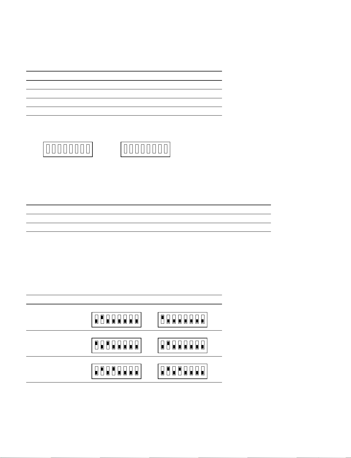
3-3. IP Address
3-3-2. Changing IP Address
The default IP address of the MVS-8000 system can be changed using dipswitch setting on CPU boards.
Device Board Group ID Unit ID
MVS-8000 CA-44 S102 (8bit) S103 (8bit)
MVE-8000 CA-44CF S102 (8bit) S103 (8bit)
CCP-8000 CA-45 S902 (8bit) S901 (8bit)
DCU-8000 CA-47 S754 (8bit) S755 (8bit)
Dipswitch on CPU board
OPEN
CLOSE
Group ID
12345678
OPEN
CLOSE
Unit ID
12345678
1. Set the DIP switch on each device as you required.
See the bit of each switch (Group ID/Unit ID) in table.
Bit settings
Bit 12345678
Group ID 1 2 4 8 16 32 Control*Data
*
Unit ID 1 2 4 8 16 32 64 128
* : These bits are factory use only. Use the bits with the default setting (CLOSE) as shipped from the factory.
The Group ID and Unit ID switch setting determines all of the LAN IP addresses (Control/Data/Peripheral LAN).
The Peripheral LAN IP address is made by adding 64 to the Group ID.
The Data LAN IP address is made by adding 128 to the Group ID.
Switcher processor IP address
IP Address Group ID Unit ID
10.2.2.1 (C)
10.130.2.1 (D)
Group ID
12345678
Unit ID
12345678
10.5.2.2 (C)
10.133.2.2 (D)
10.10.2.10 (C)
10.138.2.10 (D)
C : Control LAN
D : Data LAN
3-4
Group ID
12345678
Group ID
12345678
Unit ID
12345678
Unit ID
12345678
MVS-8000 System
SYSTEM SETUP
Page 61
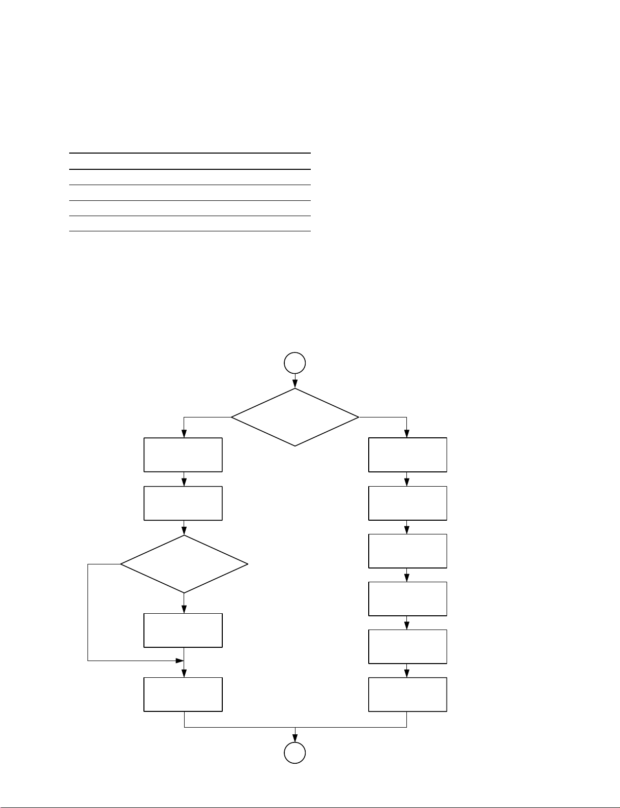
3-4. Ethernet Switch Settings
The following Ethernet switches are tested to MVS-8000 system.
Recommended models
Vendor Model name
Cisco Catalyst 29xx-XL
Cisco Catalyst 35xx-XL
Cisco Catalyst 4000 series
Cisco Catalyst 5000 series
* : Please confirm the details of a recommendation model 1 to a Cisco agency.
The Ethernet switch for MVS-8000 system requires the following settings
Follow the flowchart below to setup Ethernet switch.
1. Initialize Ethernet switch
(Required minimum settings)
2. Set VLAN
(Depending on the customer’s system situation)
Procedure of setup ethernet switch
3-4. Ethernet Switch Settings
No
C29xx-XL/35xx-XL series
Initial setting
IP Address setting
etc
Disable CDP
More than
one LAN are connected
to one Ethernet
switch
Yes
VLAN setting
Start
Ethernet switch
C4000/5000 series
IP Address setting
Disable VTP
VLAN setting
Disable
Spanning Tree
Assign Sc0
to VLAN
MVS-8000 System
SYSTEM SETUP
Disable
Spanning Tree
Disable CDP
End
3-5
Page 62

3-4. Ethernet Switch Settings
A) Initialize ethernet switch
Cisco Catalyst 29xx-XL series or Cisco Catalyst 35xx-XL series require the following parameters to
initialize.
For details, refer to Quick Start Guide supplied with a Ethernet switch
n
If the following network configuration does not fit your existing Ethernet configuration, make sure all
nodes have unique node address and are place on the appropriate network.
IP address 10.4.17.254
*1
Subnet mask 255.0.0.0
Default gateway Not used
Host name CiscoSW1
Secret password ciscosw1 (host name in small letters)
Telnet password ciscosw1 (same as secret password)
*2
*2
*2
Cluster command switch Not used
*1 : On Second and later Ethernet switch, simply subtract 1 to the node address. For example, the second Ethernet switch would have
an address of 10.4.17.253.
*2 : On Second and later Ethernet switch, simply add 1 to the number of the host name. For example, the second Ethernet switch would
have a host name of CiscoSW2.
In case of Cisco Catalyst 4000 series or Cisco Catalyst 5000 series
Cisco Catalyst 4000 series or Cisco Catalyst 5000 series requires initializing and setting VLAN together.
Step the next procedure “B) Set VLAN”.
3-6
MVS-8000 System
SYSTEM SETUP
Page 63

B) Set VLAN
In Case of Cisco Catalyst 2900-XL Series or Cisco Catalyst 3500-XL Series
VLAN is set on network through a standard browser such as Microsoft Internet Explorer or Netscape
Navigator/Communicator.
For details, refer to Quick Start Guide supplied with an Ethernet switch.
Step 1 : Disable Cisco Discovery Protocol (CDP)
To disable CDP requires Cisco Command Line Interface (CLI).
There are two ways to use CLI.
. Connect PC to a node of Ethernet switch with Ethernet cable. Access Ethernet switch through telnet.
. Connect the COM port of PC to the console port of Ethernet switch in the same manner as initial
setting. Access Ethernet switch.
1) Log in to Cisco Ethernet switch.
2) The prompt “CiscoSW1>” is displayed.
3) Enter the enable <cr>.
4) The prompt “CiscoSW1 #” is displayed.
5) Enter the configure terminal and [Enter].
6) The prompt “CiscoSW1 (config) #” is displayed.
7) Enter no cdp run and [Enter]
8) Enter end and [Enter].
9) The prompt “CiscoSW1 #” is displayed.
10) Enter show running-config prompt and [Enter].
11) Check to see “no cdp run” on monitor.
12) Enter write memory and [Enter].
13) Saved the setting on Cisco Ethernet switch.
14) Enter disable and [Enter].
15) The prompt “CiscoSW1>” is displayed.
16) Enter exit <cr> to exit telnet.
3-4. Ethernet Switch Settings
Step 2 : Set VLAN
n
If separated Ethernet switches are used for each of Control LAN, Data LAN and Peripheral LAN, it does
not require.
It requires to separate from each network, Control LAN, Data LAN, and Peripheral LAN to set VALN.
Use port 1 through 10 for Control LAN, port 11 through 20 for Data LAN, after 21 port for Peripheral
LAN.
For details, refer to Software Configuration Guide.
Assign port 1 through 10 to VLAN1, port 11 through 20 for VLAN2, port 21 through 24 for VLAN3.
Step 3 : Disable Spanning-Tree on VLANs
Connect PC to a node of Ethernet switch with Ethernet cable.
Browser requires to setup as Quick Start Guide
1) Access the Ethernet switch via PC
2) Open Cluster Management Suite of the switch.
3) Disable Spanning-tree protocol as Software Configuration Guide.
n
Save new configuration data.
If new configuration is not saved, the setting is back when re-booting.
MVS-8000 System
SYSTEM SETUP
3-7
Page 64

3-4. Ethernet Switch Settings
In Case of Cisco Catalyst 4000 Series or Cisco Catalyst 5000 Series
The settings require Cisco Command Line Interface (CLI).
For details of operation, refer to Family Software Configuration Guide of Catalyst 4000 series or Cisco
Catalyst 5000 series.
The required parameters for MVS-8000 system are follows.
There are two interfaces to setup IP address in Catalyst 4000 series.
They are called sc0 and mel.
The sc0 port is normal Ethernet port.
The switch can be accessed and set by setting IP address to sc0 and connecting a PC to any of normal
Ethernet ports.
The mel port is 10 BASE-T port on supervisor engine.
The switch can be set by connecting a PC to this port.
Step 1 : IP Address
Both IP address “sc0” and “mel” are required.
The network segment of the sc0 and mel ports is recommended to be separated.
Example
sc0 me1
IP Address 10.4.17.254 192.168.0.254
Subnet Mask 255.0.0.0 255.255.255.0
Step 2 : Disable VTP
Disable VTP as Catalyst 4000/5000 Family Software Configuration Guide.
Connect PC to a node of Ethernet switch with Ethernet cable.
Browser requires to setup as Quick Start Guide.
1) Access the Ethernet switch via personal computer.
2) Open Cluster Management Suite of the switch.
Step 3 : Set VLAN
The separated VLAN settings are required to control LAN, data LAN, and peripheral LAN.
They require more than 3 VLAN setting.
Name VLAN for each network.
Assign port as system setting to named VLAN.
Example of C4003 96 port
controlLAN 1 Port 1 to 12
controlLAN2 Port 13 to 14
dataLAN1 Port 25 to 36
dataLAN2 Port 37 to 48
peripheralLAN1 Port 49 to 60
peripheralLAN2 Port 61 to 72
managementLAN1 Port 73 to 84
managementLAN2 Port 85 to 96
The managementLAN 1/2 manage Ethernet switch and system with the above setting.
3-8
MVS-8000 System
SYSTEM SETUP
Page 65

Step 4 : Disable Spanning-Tree
Disable all spanning tree on VLAN.
Refer to Catalyst 4000/5000 Family Software Configuration Guide
Step 5 : Assign sc0 to VLAN
Assign sc0 to VLAN except Control LAN, Data LAN, and Peripheral LAN.
Refer to Catalyst 4000/5000 Family Software Configuration Guide
Step 6 : Disable Cisco Discovery Protocol (CDP)
Disable CDP globally.
Refer to Catalyst 4000/5000 Family Software Configuration Guide
3-5. Software Installation
The current software version is displayed by pressing the following buttons in order.
“ENG SETUP”→“System”→“Install” to show the Install menu.
Select the desired software to install on the Install menu and press the Install button. Then installation
starts.
The status area displays the device ID of each device, and the version, and released date.
3-4. Ethernet Switch Settings
3-5. Software Installation
3-6. Engineering Setups
3-6. Engineering Setups
The engineering setups are required to configure the system connected to switcher, DME, control panel,
DCU and external devices.
The “ENG SETUP” of menu panel GUI provides you the following items can be set.
. Recognizing devices on the LAN
. Switching the signal format
. Switching the screen aspect ratio
. Selecting the state after powering on
. Time setting
. Signal assignment to cross-point buttons
. Output signal assignment
For detail setup of ENG SETUP, refer to User’s Guide Volume 1 Chapter 1 “Setup” and User’s Guide
Volume 2 Chapter 17 “Engineering Setup”.
MVS-8000 System
SYSTEM SETUP
3-9
Page 66
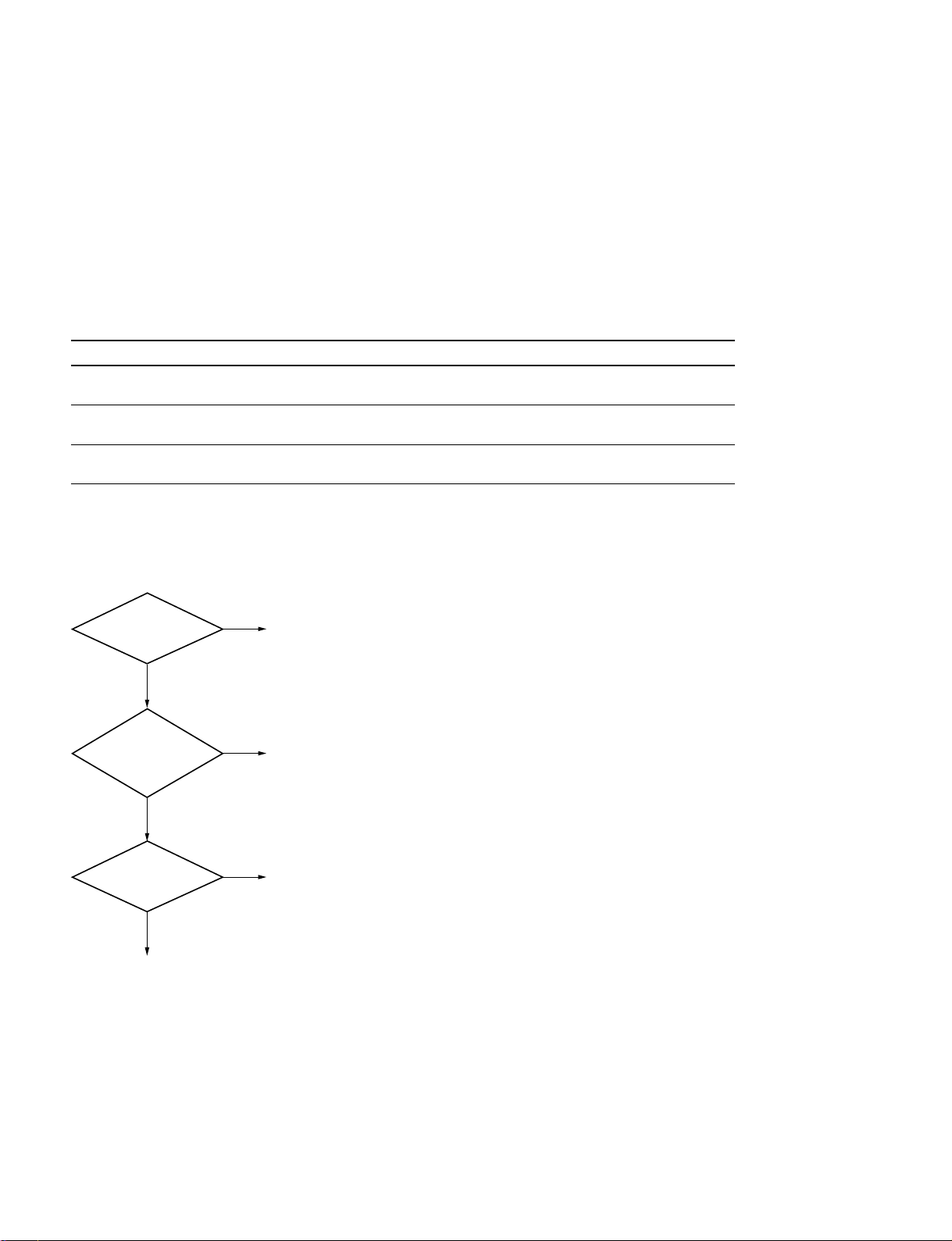
3-7. Tally Setup
3-7. Tally Setup
This section describes how to set the tally (system tally (S-Bus), parallel tally and serial tally).
n
If tally is not used in the systems such as the MVS-8000 standalone configuration, this setting is not
required.
Definition of system
Major system configurations are classified into the three systems of System 1, System 2 and System
3. This classification is used only for the convenience of description in this manual as described below.
System Description
System 1 The MVS standalone system
In the case when independent MVS-8000 system is going to use tally
System 2*1The MVS-8000 + MKS-808x (Aux Remote Panel) system (having no tally)
The system that is configured by the combination the MVS-8000 system with the AUX Remote Panel
System 3 The MVS-8000 + router system
The system that is configured by the combination of MVS-8000 system with the Sony routing switcher
*1 : The equipment before Ver. 1.20 requires primary station. (Sony S-BUS Routing Switcher or BKPF-R70A is required.)
In the case if the equipment of Ver. 1.30 and higher is not connected to router, set the primary station function of the MVS-8000 to
the ON position.
*2 : In the system using the AUX Remote Panel, the specified items must be set even when tally setup is not going to be made.
*2
Confirm in which system your equipment corresponds by referring to the following flow chart.
S-Bus is connected.
Yes
AUX Bus Remote
Panel (MKS-808X)
Yes
Router is connected.
Yes
System 3
No
No
No
System 1
System 3
System 2
3-10
MVS-8000 System
SYSTEM SETUP
Page 67

Confirming the setting items
The following items marked with the white round circle are required to be set in the respective systems.
O = Setting is required.
3-7. Tally Setup
System
11
1 System
11
22
2 System
22
33
3
33
Switcher Output Assignment OOO
Router OOO
Group Tally O (default) _O
Wiring __O
Tally Enable O_O
Tally Copy O_O
Parallel Tally O_O
System
11
1 System
11
22
2 System
22
33
3
33
Setting primary station _O*O
Setting MKS-808x _OO
* : Complete the setup as the primary station at the router side or at the MVS-8000 side.
** : In the case that the AUX Bus Remote Panel is connected.
**
MVS-8000 System
SYSTEM SETUP
3-11
Page 68
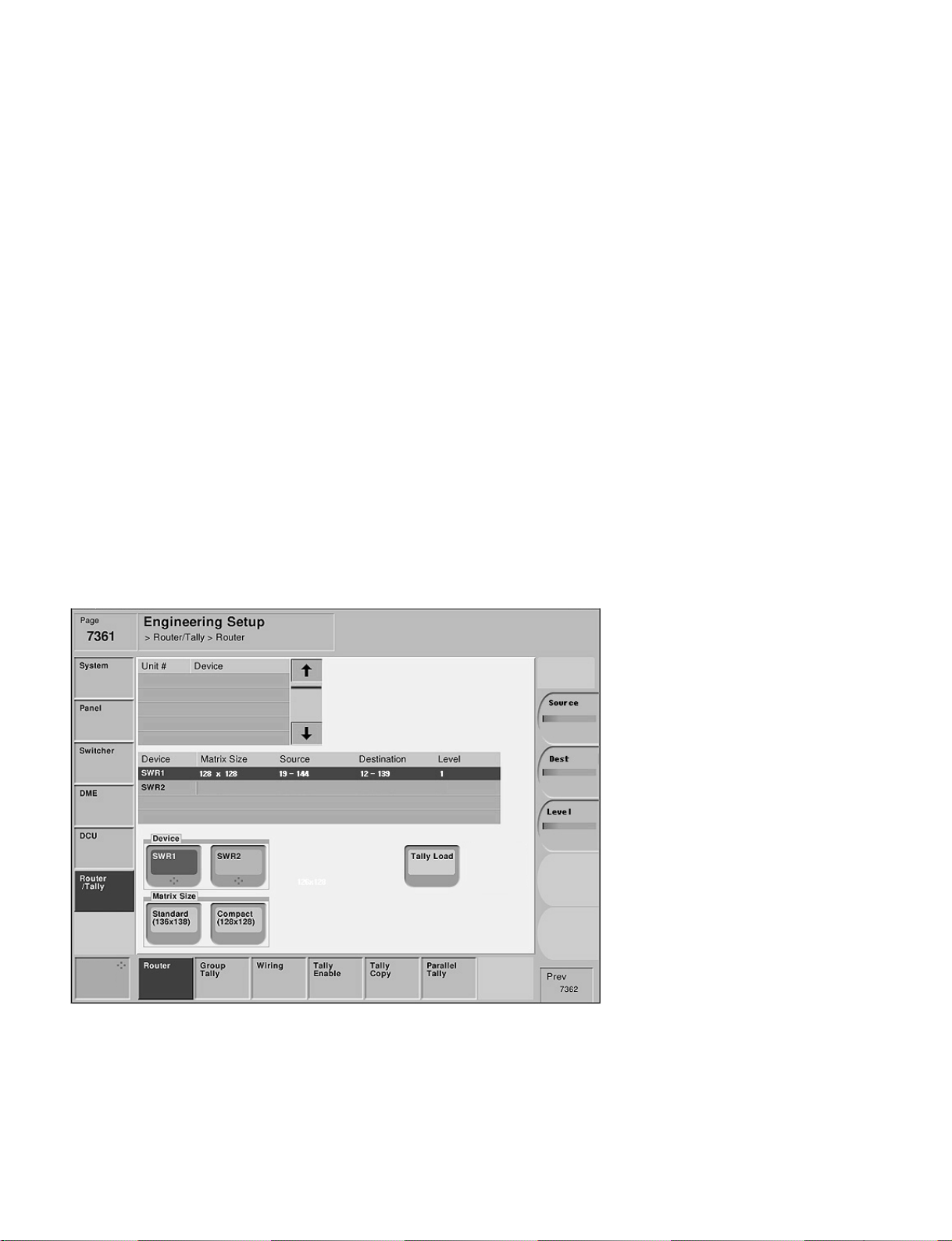
3-7. Tally Setup
3-7-1. Setting Router
Engineering Setup → Router/Tally → Router
Page 7361
This menu is used to assign the input and output signals of the switcher on the virtual matrix space of the
S-BUS.
When setting the tallies, the input and output signals to and from the equipment (such as router, switcher
and others) that has the crosspoints should be assigned on the virtual matrix space. When they are assigned, serial numbers (unique) are given to all inputs and outputs on the matrix space, of all the equipment that are to be controlled. These serial numbers are necessary for the integrated handling of the
signals.
By assigning all of the equipment on virtual matrix space, i.e., by mapping, the input and output terminals
of each equipment shall have the virtual addresses. When this setting is complete, all of the equipment
that have crosspoints and constitute the system are assigned on the virtual matrix space. Generation of the
tallies are managed and handled by the virtual numbers that are assigned by this setting.
n
For router setup, refer to the System Setup Manual of the router.
This setup is used by the interface (on the S-Bus protocol) of switcher with router. However, because the
virtual numbers are required to be set in the tally system of even the systems that are not connected to SBus/router, this setting must be implemented.
3-12
Menu screen
MVS-8000 System
SYSTEM SETUP
Page 69

Setting items
3-7. Tally Setup
System
Device SWR1/SWR2 SWR1/SWR2 SWR1/SWR2
Matrix Size Standard Standard Standard/Compact
Setting Setting Setting
Source
Destination
Level : 1 Level : 1 Level : 1 to 8
* : Set the top value of matrix for both of the Source and Destination. The end value is determined automatically in accordance with the
Matrix Size.
As to the Source Address, the same Source Address can be duplicated and be set using SWR1/SWR2.
The value with parenthesis (S) is the value when Standard mode is selected. The value with parenthesis (C) is the value when
Compact mode is selected.
For the system
11
1
11
11
1 System
11
*
: 1 Source* : 1 Source* : 1 to Max (889 (S), 897 (C))
*
:1 Destination* :1 Destination* : 1 to Max (887 (S), 897 (C))
22
2 System
22
33
3
33
Select “Standard” that is the default setup of Matrix Size for the system 1.
Default setup :
Matrix Size : standard (136 x 138)
For the system
22
2
22
Select “Standard” that is the default setup of Matrix Size for the system 2.
Default setup :
Matrix Size : standard (136 x 138)
For the system
33
3
33
Select either “Standard” or “Compact” of Matrix Size depending on the number of units of the equipment
consisting the system.
When “Standard” (136 x 138) is selected, the switcher is assigned to the S-Bus space with the full size.
(All of the inputs and outputs of the switcher can be assigned to the S-Bus space.)
When “Compact” (128 x 128) is selected, the switcher is assigned to the S-Bus space with the compact
size.
(Not all of the inputs and outputs of the switcher are assigned to the S-Bus space, but the S-Bus space can
be effectively used.)
n
If two units of the MVS-8000 switcher processor are connected, each switcher processor must be set
independently. Select the target device to be set using “Device” of this menu. Assign each switcher
processor to SWR1/SWR2 using the menu screen (Engineering Setup → System → Network Config).
MVS-8000 System
SYSTEM SETUP
3-13
Page 70

3-7. Tally Setup
Setup example : For the system
33
3
33
System : MVS-8000 x 1 unit, router x 1 unit (8 x 4)
The MVS-8000 is assigned to (virtual source No. 19 to No. 146 and virtual destination
No. 12 to No. 139) on the virtual matrix space.
Select “Compact” (128 x 128) of the Matrix Size.
n
For setting a router, refer also to the System Setup Manual of the router.
Page 7332
Device Matrix Size Source Destination Level
SWR1 128 x 128 19 12 1
SWR2
Relation between physical and virtual numbers when assigning on virtual matrix space.
Input
Physical terminals → Virtual terminals
Router 1 7
28
39
410
511
612
713
814
SWR1 1 19
220
||
126 144
127 145
128 146
Router 1 5
SWR1 1 12
Output
Physical terminals → Virtual terminals
26
37
48
||
128 139
3-14
MVS-8000 System
SYSTEM SETUP
Page 71
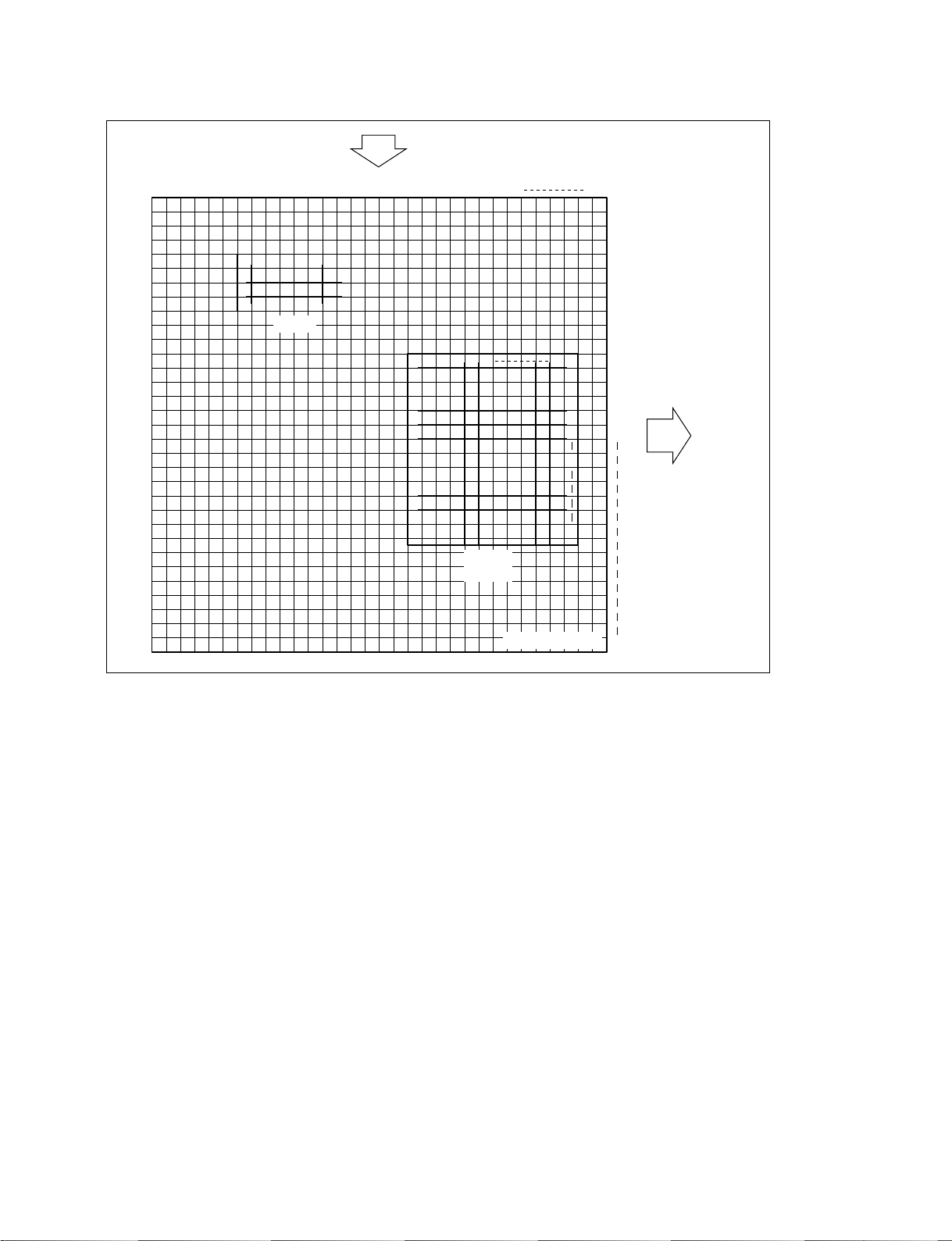
Input
3-7. Tally Setup
1 2 3 4 5 6 7 8 9101112131415
1234567
1
2
3
4
Router
161718
1920 212223 242526
123456
MVS
(SWR1)
1
127
2
3
4
5
6
~
128
Virtual matrix
1024
1
2
3
4
5
6
7
8
9
10
11
12
13
14
15
16
17
1024
Output
Assignment to virtual matrix space
MVS-8000 System
SYSTEM SETUP
3-15
Page 72

3-7. Tally Setup
MVS-8000 matrix assignment (Standard mode)
Source
No. Source
1 Primary 1
2 Primary 2
3 Primary 3
4 Primary 4
5 Primary 5
6 Primary 6
7 Primary 7
8 Primary 8
9 Primary 9
10 Primary 10
11 Primary 11
12 Primary 12
13 Primary 13
14 Primary 14
15 Primary 15
16 Primary 16
17 Primary 17
18 Primary 18
19 Primary 19
20 Primary 20
21 Primary 21
22 Primary 22
23 Primary 23
24 Primary 24
25 Primary 25
26 Primary 26
27 Primary 27
28 Primary 28
29 Primary 29
30 Primary 30
31 Primary 31
32 Primary 32
33 Primary 33
34 Primary 34
35 Primary 35
36 Primary 36
37 Primary 37
38 Primary 38
39 Primary 39
40 Primary 40
No. Source
41 Primary 41
42 Primary 42
43 Primary 43
44 Primary 44
45 Primary 45
46 Primary 46
47 Primary 47
48 Primary 48
49 Primary 49
50 Primary 50
51 Primary 51
52 Primary 52
53 Primary 53
54 Primary 54
55 Primary 55
56 Primary 56
57 Primary 57
58 Primary 58
59 Primary 59
60 Primary 60
61 Primary 61
62 Primary 62
63 Primary 63
64 Primary 64
65 Primary 65
66 Primary 66
67 Primary 67
68 Primary 68
69 Primary 69
70 Primary 70
71 Primary 71
72 Primary 72
73 Primary 73
74 Primary 74
75 Primary 75
76 Primary 76
77 Primary 77
78 Primary 78
79 Primary 79
80 Primary 80
3-16
MVS-8000 System
SYSTEM SETUP
Page 73

3-7. Tally Setup
No. Source
81 Black
82 White
83 Color Bkgd 1
84 Color Bkgd 2
85 Frame Memory 1
86 Frame Memory 2
87 Frame Memory 3
88 Frame Memory 4
89 Frame Memory 5
90 Frame Memory 6
91 Frame Memory 7
92 Frame Memory 8
93 Color Correction 1
94 Color Correction 2
95 DME Monitor Video
96 DME Monitor Key
97 M/E-1 Out 1
98 M/E-1 Out 2
99 M/E-1 Out 3
100 M/E-1 Out 4
101 M/E-1 Out 5
102 M/E-1 Out 6
103 M/E-1 Proc Video
104 M/E-1 Proc Key
105 M/E-2 Out 1
106 M/E-2 Out 2
107 M/E-2 Out 3
108 M/E-2 Out 4
109 M/E-2 Out 5
110 M/E-2 Out 6
111 M/E-2 Proc Video
112 M/E-2 Proc Key
113 M/E-3 Out 1
114 M/E-3 Out 2
115 M/E-3 Out 3
116 M/E-3 Out 4
117 M/E-3 Out 5
118 M/E-3 Out 6
119 M/E-3 Proc Video
120 M/E-3 Proc Key
121 P/P Out 1
122 P/P Out 2
123 P/P Out 3
No. Source
124 P/P Out 4
125 P/P Out 5
126 P/P Out 6
127 P/P Proc Video
128 P/P Proc Key
129 DME1
130 DME2
131 DME3
132 DME4
133 DME5
134 DME6
135 DME7
136 DME8
MVS-8000 System
SYSTEM SETUP
3-17
Page 74

3-7. Tally Setup
Destination
**
*
No. Destination Bus
1 Out 1 Assignable Output
2 Out 2 Assignable Output
3 Out 3 Assignable Output
4 Out 4 Assignable Output
5 Out 5 Assignable Output
6 Out 6 Assignable Output
7 Out 7 Assignable Output
8 Out 8 Assignable Output
9 Out 9 Assignable Output
10 Out 10 Assignable Output
11 Out 11 Assignable Output
12 Out 12 Assignable Output
13 Out 13 Assignable Output
14 Out 14 Assignable Output
15 Out 15 Assignable Output
16 Out 16 Assignable Output
17 Out 17 Assignable Output
18 Out 18 Assignable Output
19 Out 19 Assignable Output
20 Out 20 Assignable Output
21 Out 21 Assignable Output
22 Out 22 Assignable Output
23 Out 23 Assignable Output
24 Out 24 Assignable Output
25 Out 25 Assignable Output
26 Out 26 Assignable Output
27 Out 27 Assignable Output
28 Out 28 Assignable Output
29 Out 29 Assignable Output
30 Out 30 Assignable Output
31 Out 31 Assignable Output
32 Out 32 Assignable Output
33 Out 33 Assignable Output
34 Out 34 Assignable Output
35 Out 35 Assignable Output
36 Out 36 Assignable Output
37 Out 37 Assignable Output
38 Out 38 Assignable Output
39 Out 39 Assignable Output
40 Out 40 Assignable Output
41 Out 41 Assignable Output
42 Out 42 Assignable Output
**
**
*
No. Destination Bus
**
**
**
**
**
**
**
**
**
**
**
**
**
**
**
**
**
**
**
**
**
**
**
**
**
**
**
**
**
**
**
**
**
**
**
**
**
**
**
**
**
**
43 Out 43 Assignable Output
44 Out 44 Assignable Output
45 Out 45 Assignable Output
46 Out 46 Assignable Output
47 Out 47 Assignable Output
48 Out 48 Assignable Output
49 Monitor Out 1 Monitor 1
50 Monitor Out 2 Monitor 2
51 Monitor Out 3 Monitor 3
52 Monitor Out 4 Monitor 4
53 Monitor Out 5 Monitor 5
54 Monitor Out 6 Monitor 6
55 Monitor Out 7 Monitor 7
56 Monitor Out 8 Monitor 8
57 M/E-1 Bkgd A
58 M/E-1 Bkgd B
59 M/E-1 Utility 1
60 M/E-1 Utility 2
61 M/E-1 Key 1 Fill
62 M/E-1 Key 1 Source
63 M/E-1 Key 2 Fill
64 M/E-1 Key 2 Source
65 M/E-1 Key 3 Fill
66 M/E-1 Key 3 Source
67 M/E-1 Key 4 Fill
68 M/E-1 Key 4 Source
69 M/E-1 Dme Video
70 M/E-1 Dme Key
71 M/E-1 Ext Dme
72 M/E-2 Bkgd A
73 M/E-2 Bkgd B
74 M/E-2 Utility 1
75 M/E-2 Utility 2
76 M/E-2 Key 1 Fill
77 M/E-2 Key 1 Source
78 M/E-2 Key 2 Fill
79 M/E-2 Key 2 Source
80 M/E-2 Key 3 Fill
81 M/E-2 Key 3 Source
82 M/E-2 Key 4 Fill
83 M/E-2 Key 4 Source
84 M/E-2 Dme Video
**
**
**
**
**
**
**
3-18
MVS-8000 System
SYSTEM SETUP
Page 75

3-7. Tally Setup
**
*
No. Destination Bus
**
85 M/E-2 Dme Key
86 M/E-2 Ext Dme
87 M/E-3 Bkgd A
88 M/E-3 Bkgd B
89 M/E-3 Utility 1
90 M/E-3 Utility 2
91 M/E-3 Key 1 Fill
92 M/E-3 Key 1 Source
93 M/E-3 Key 2 Fill
94 M/E-3 Key 2 Source
95 M/E-3 Key 3 Fill
96 M/E-3 Key 3 Source
97 M/E-3 Key 4 Fill
98 M/E-3 Key 4 Source
99 M/E-3 Dme Video
100 M/E-3 Dme Key
101 M/E-3 Ext Dme
102 P/P Bkgd A (DSK Bkgd 1)
103 P/P Bkgd B (DSK Bkgd 2)
104 P/P Utility 1
105 P/P Utility 2 (DSK Bkgd 3)
106 P/P Key 1 Fill
107 P/P Key 1 Source
108 P/P Key 2 Fill
109 P/P Key 2 Source
110 P/P Key 3 Fill
111 P/P Key 3 Source
112 P/P Key 4 Fill
113 P/P Key 4 Source
114 P/P Dme Video (DSK Bkgd 4)
115 P/P Dme Key
116 P/P Ext Dme
117 DME Utility 1
118 DME Utility 2
119 Frame Memory Source 1
120 Frame Memory Source 2
121 Reserved
122 Reserved
123 DME 1 Video
124 DME 1 Key
125 DME 2 Video
126 DME 2 Key
127 DME 3 Video
**
*
No. Destination Bus
**
128 DME 3 Key
129 DME 4 Video
130 DME 4 Key
131 DME 5 Video
132 DME 5 Key
133 DME 6 Video
134 DME 6 Key
135 DME 7 Video
136 DME 7 Key
137 DME 8 Video
138 DME 8 Key
* : To switch the XPT from the S-Bus remote control, select the corre-
sponding bus number.
** : This is the output (bus) that is set by the Output Assign of the switcher
setup. Among the buses of AUX 1 to 48, Edit PVW and DME Monitor,
only the buses that are set by the Output Assign, are controlled.
MVS-8000 System
SYSTEM SETUP
3-19
Page 76

3-7. Tally Setup
MVS-8000 matrix assignment (Compact mode)
Source
No. Source
1 Primary 1
2 Primary 2
3 Primary 3
4 Primary 4
5 Primary 5
6 Primary 6
7 Primary 7
8 Primary 8
9 Primary 9
10 Primary 10
11 Primary 11
12 Primary 12
13 Primary 13
14 Primary 14
15 Primary 15
16 Primary 16
17 Primary 17
18 Primary 18
19 Primary 19
20 Primary 20
21 Primary 21
22 Primary 22
23 Primary 23
24 Primary 24
25 Primary 25
26 Primary 26
27 Primary 27
28 Primary 28
29 Primary 29
30 Primary 30
31 Primary 31
32 Primary 32
33 Primary 33
34 Primary 34
35 Primary 35
36 Primary 36
37 Primary 37
38 Primary 38
39 Primary 39
40 Primary 40
No. Source
41 Primary 41
42 Primary 42
43 Primary 43
44 Primary 44
45 Primary 45
46 Primary 46
47 Primary 47
48 Primary 48
49 Primary 49
50 Primary 50
51 Primary 51
52 Primary 52
53 Primary 53
54 Primary 54
55 Primary 55
56 Primary 56
57 Primary 57
58 Primary 58
59 Primary 59
60 Primary 60
61 Primary 61
62 Primary 62
63 Primary 63
64 Primary 64
65 Primary 65
66 Primary 66
67 Primary 67
68 Primary 68
69 Primary 69
70 Primary 70
71 Primary 71
72 Primary 72
73 Primary 73
74 Primary 74
75 Primary 75
76 Primary 76
77 Primary 77
78 Primary 78
79 Primary 79
80 Primary 80
3-20
MVS-8000 System
SYSTEM SETUP
Page 77

3-7. Tally Setup
No. Source
81 Black
82 White
83 Color Bkgd 1
84 Color Bkgd 2
85 Frame Memory 1
86 Frame Memory 2
87 Frame Memory 3
88 Frame Memory 4
89 Frame Memory 5
90 Frame Memory 6
91 Frame Memory 7
92 Frame Memory 8
93 Color Correction 1
94 Color Correction 2
95 DME Monitor Video
96 DME Monitor Key
97 M/E-1 Out 1
98 M/E-1 Out 2
99 M/E-1 Out 3
100 M/E-1 Out 4
101 M/E-1 Out 5
102 M/E-1 Out 6
103 M/E-2 Out 1
104 M/E-2 Out 2
105 M/E-2 Out 3
106 M/E-2 Out 4
107 M/E-2 Out 5
108 M/E-2 Out 6
109 M/E-3 Out 1
110 M/E-3 Out 2
111 M/E-3 Out 3
112 M/E-3 Out 4
113 M/E-3 Out 5
114 M/E-3 Out 6
115 P/P Out 1
116 P/P Out 2
117 P/P Out 3
118 P/P Out 4
119 P/P Out 5
120 P/P Out 6
121 DME1
122 DME2
123 DME3
No. Source
124 DME4
125 DME5
126 DME6
127 DME7
128 DME8
MVS-8000 System
SYSTEM SETUP
3-21
Page 78

3-7. Tally Setup
Destination
**
*
No. Destination Bus
1 Out 1 Assignable Output
2 Out 2 Assignable Output
3 Out 3 Assignable Output
4 Out 4 Assignable Output
5 Out 5 Assignable Output
6 Out 6 Assignable Output
7 Out 7 Assignable Output
8 Out 8 Assignable Output
9 Out 9 Assignable Output
10 Out 10 Assignable Output
11 Out 11 Assignable Output
12 Out 12 Assignable Output
13 Out 13 Assignable Output
14 Out 14 Assignable Output
15 Out 15 Assignable Output
16 Out 16 Assignable Output
17 Out 17 Assignable Output
18 Out 18 Assignable Output
19 Out 19 Assignable Output
20 Out 20 Assignable Output
21 Out 21 Assignable Output
22 Out 22 Assignable Output
23 Out 23 Assignable Output
24 Out 24 Assignable Output
25 Out 25 Assignable Output
26 Out 26 Assignable Output
27 Out 27 Assignable Output
28 Out 28 Assignable Output
29 Out 29 Assignable Output
30 Out 30 Assignable Output
31 Out 31 Assignable Output
32 Out 32 Assignable Output
33 Out 33 Assignable Output
34 Out 34 Assignable Output
35 Out 35 Assignable Output
36 Out 36 Assignable Output
37 Out 37 Assignable Output
38 Out 38 Assignable Output
39 Out 39 Assignable Output
40 Out 40 Assignable Output
41 Out 41 Assignable Output
42 Out 42 Assignable Output
**
**
*
No. Destination Bus
**
**
**
**
**
**
**
**
**
**
**
**
**
**
**
**
**
**
**
**
**
**
**
**
**
**
**
**
**
**
**
**
**
**
**
**
**
**
**
**
**
**
43 Out 43 Assignable Output
44 Out 44 Assignable Output
45 Out 45 Assignable Output
46 Out 46 Assignable Output
47 Out 47 Assignable Output
48 Out 48 Assignable Output
49 Monitor Out 1 Monitor 1
50 Monitor Out 2 Monitor 2
51 Monitor Out 3 Monitor 3
52 Monitor Out 4 Monitor 4
53 Monitor Out 5 Monitor 5
54 Monitor Out 6 Monitor 6
55 Monitor Out 7 Monitor 7
56 Monitor Out 8 Monitor 8
57 M/E-1 Bkgd A
58 M/E-1 Bkgd B
59 M/E-1 Utility 1
60 M/E-1 Utility 2
61 M/E-1 Key 1 Fill
62 M/E-1 Key 1 Source
63 M/E-1 Key 2 Fill
64 M/E-1 Key 2 Source
65 M/E-1 Key 3 Fill
66 M/E-1 Key 3 Source
67 M/E-1 Key 4 Fill
68 M/E-1 Key 4 Source
69 M/E-2 Bkgd A
70 M/E-2 Bkgd B
71 M/E-2 Utility 1
72 M/E-2 Utility 2
73 M/E-2 Key 1 Fill
74 M/E-2 Key 1 Source
75 M/E-2 Key 2 Fill
76 M/E-2 Key 2 Source
77 M/E-2 Key 3 Fill
78 M/E-2 Key 3 Source
79 M/E-2 Key 4 Fill
80 M/E-2 Key 4 Source
81 M/E-3 Bkgd A
82 M/E-3 Bkgd B
83 M/E-3 Utility 1
84 M/E-3 Utility 2
**
**
**
**
**
**
**
3-22
MVS-8000 System
SYSTEM SETUP
Page 79

3-7. Tally Setup
**
*
No. Destination Bus
**
85 M/E-3 Key 1 Fill
86 M/E-3 Key 1 Source
87 M/E-3 Key 2 Fill
88 M/E-3 Key 2 Source
89 M/E-3 Key 3 Fill
90 M/E-3 Key 3 Source
91 M/E-3 Key 4 Fill
92 M/E-3 Key 4 Source
93 P/P Bkgd A (DSK Bkgd 1)
94 P/P Bkgd B (DSK Bkgd 2)
95 P/P Utility 1
96 P/P Utility 2 (DSK Bkgd 3)
97 P/P Key 1 Fill
98 P/P Key 1 Source
99 P/P Key 2 Fill
100 P/P Key 2 Source
101 P/P Key 3 Fill
102 P/P Key 3 Source
103 P/P Key 4 Fill
104 P/P Key 4 Source
105 P/P Dme Video (DSK Bkgd 4)
106 DME Utility 1
107 DME Utility 2
108 Frame Memory Source 1
109 Frame Memory Source 2
110 Reserved
111 Reserved
112 DME 1 Video
113 DME 1 Key
114 DME 2 Video
115 DME 2 Key
116 DME 3 Video
117 DME 3 Key
118 DME 4 Video
119 DME 4 Key
120 DME 5 Video
121 DME 5 Key
122 DME 6 Video
123 DME 6 Key
124 DME 7 Video
125 DME 7 Key
126 DME 8 Video
127 DME 8 Key
**
*
No. Destination Bus
**
128 _
* : To switch the XPT from the S-Bus remote control, select the corre-
sponding bus number.
** : This is the output (bus) that is set by the Output Assign of the switcher
setup. Among the buses of AUX 1 to 48, Edit PVW and DME Monitor,
only the buses that are set by the Output Assign, are controlled.
MVS-8000 System
SYSTEM SETUP
3-23
Page 80
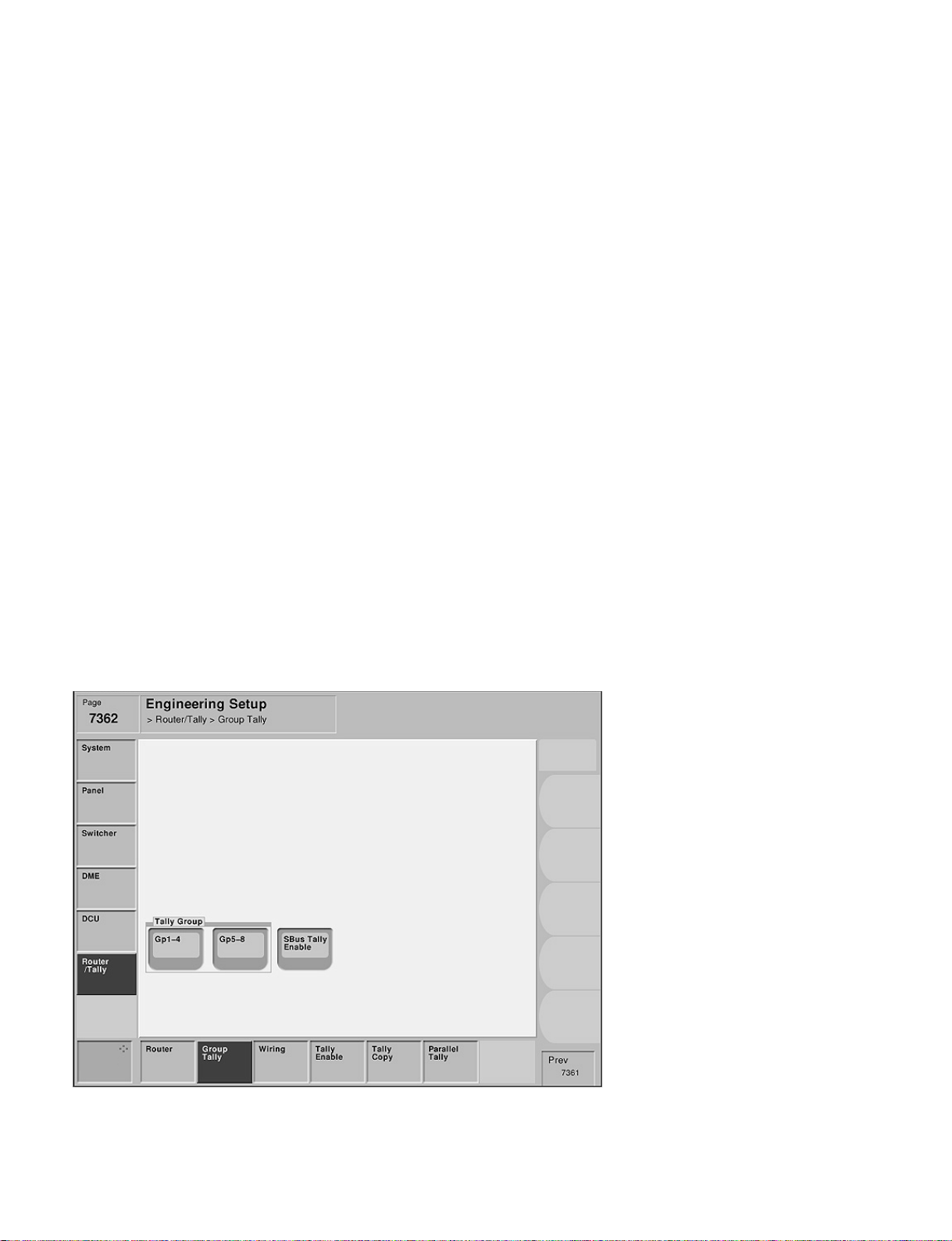
3-7. Tally Setup
3-7-2. Setting Group Tally
Engineering Setup → Router/Tally → Group Tally
Page 7362
This menu is used to select either the tally groups 1 to 4 or the tally groups 5 to 8 shall be used by as
many as the four tally groups at the maximum.
The S-Bus tally can be enabled or disabled as required.
In the video switching systems, there are many occasions that two or more independent jobs are carried
out within the same switching system.
For example, recording of the on-air program by VTR or by slow motion VTR while on-air is under way
or distributing the on-air program to the local network stations while on-air is under way is performed.
As the result, sophisticated tally system is required in order to correspond to the sophisticated output
system.
If a video switching system becomes sophisticated, the tally system that aims at attracting attention of
operators can become the cause of confusion on the other hand. In order to avoid this confusion, the entire
tally system can be divided into the two systems. After the entire tally system is divided into the two
systems, one tally system can be, for example, assigned to the on-air tally while the other tally system can
be assigned to the off-air live tally. The two colors of red and green can be used for the display of each
tally system.
Each combination of red tally and green tally as described above is called tally group.
The S-Bus protocol is capable of controlling the eight tally groups (system tally red/green tally) of the
tally groups 1 to 8.
The MVS-8000 is capable of controlling the four tally groups.
The S-Bus tally is required to be set when the tally information supplied from the MVS-8000 is going to
be sent to the equipment for example UMD (Under Monitor Display) that indicates tally, via the S-BUS.
3-24
Menu screen
MVS-8000 System
SYSTEM SETUP
Page 81

Setting items
3-7. Tally Setup
System
Tally Gp Gp1-4/Gp5-8 Gp1-4/Gp5-8 Gp1-4/Gp5-8
SBus Tally Enable Disable Disable Enable/Disable
For the system
11
1
11
11
1 System
11
22
2 System
22
33
3
33
Select “Gp1-4” or “Gp5-8” as desired from the Tally Group for the system 1. As to the S-Bus Tally,
select “Disable” (i.e., the “SBus Tally Enable” button is not selected) because there is no equipment that
is connected by S-Bus.
For the system
22
2
22
This setting is not required for the system 2 because the system 2 does not use tally. Select either
“Gp1-4” or “Gp5-8” from the Tally Group for the system 2. As to the S-Bus Tally, select “Disable”
because UMD is not connected to the system 2.
For the system
33
3
33
Select “Gp1-4” or “Gp5-8” as desired from the Tally Group for the system 3. As to the S-Bus Tally,
select “Enable” (i.e., select the “SBus Tally Enable” button) if there is any equipment (such as UMD) that
is connected by S-Bus.
MVS-8000 System
SYSTEM SETUP
3-25
Page 82
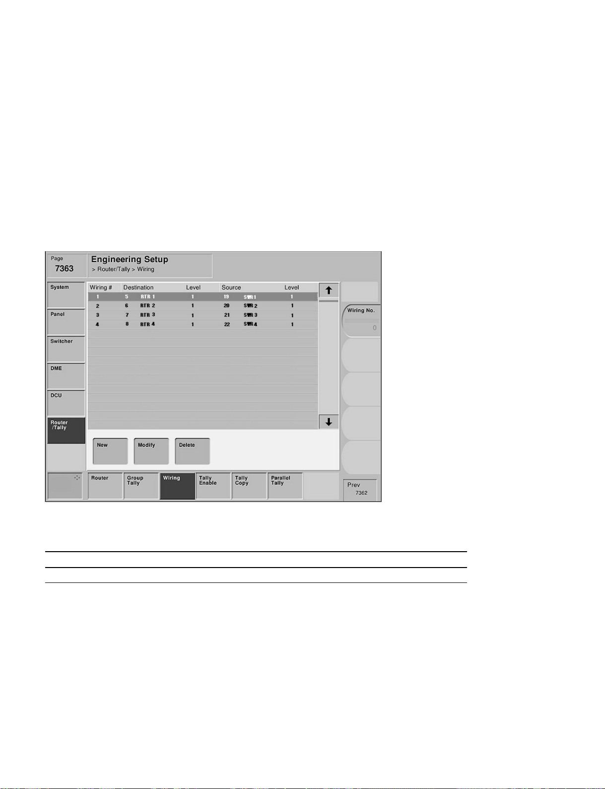
3-7. Tally Setup
3-7-3. Setting Wiring
Engineering Setup → Router/Tally → Wiring
Page 7363
This menu is set in order to trace back the connection and to locate the source of the connected equipment
starting from the output of the final stage.
In the system configuration where inputs and outputs of a switcher are connected to a router, the connection relationship (wiring) between the switcher and the router on the matrix space must be set.
In order to implement this setting, take reading of the connection between the switcher and router from
the system wiring diagram and set the wiring between the input/output terminals and virtual numbers.
After the wiring is set, we can know which input/output of which equipment are connected to which
input/output of which equipment.
Menu screen
Setting items
System
Wiring Setting is not required Setting is not required Setting is required
For the system
11
1 System
11
11
1
11
22
2 System
22
3
33
33
Because crosspoints of the equipment are not connected (router is not connected) in the system 1, this
setting is not necessary.
For the system
22
2
22
Because crosspoints of the equipment are not connected (router is not connected) in the system 2, this
setting is not necessary.
For the system
33
3
33
Since inputs and outputs of the MVS-8000 are connected to router in the system 3, set the corresponding virtual numbers.
3-26
MVS-8000 System
SYSTEM SETUP
Page 83

3-7. Tally Setup
Setup example : For the system
33
3
33
System : MVS-8000 x 1 unit, router x 1 unit (8 x 4)
1. Connect Destination 1 (virtual No. 5) of a router to Primary 1 (virtual No. 19) of the MVS-8000.
2. Connect Destinations 2 to 4 (virtual No. 6 to 8) of a router to Primary 2 to 4 (virtual No. 20 to 23) of
the MVS-8000.
Page 7363
Wiring# Destination Level Source Level
1 5 RTR1
2 6 RTR2
3 7 RTR3
4 8 RTR4
* : The Source/Destination Names that are set from the Router/MVS side are displayed.
*
*
*
*
1 19 SWR1
1 20 SWR2
1 21 SWR3
1 22 SWR4
Virtual destination number Virtual source number
519
620
721
822
*
*
*
*
1
1
1
1
Connection information
MVS-8000 System
SYSTEM SETUP
3-27
Page 84
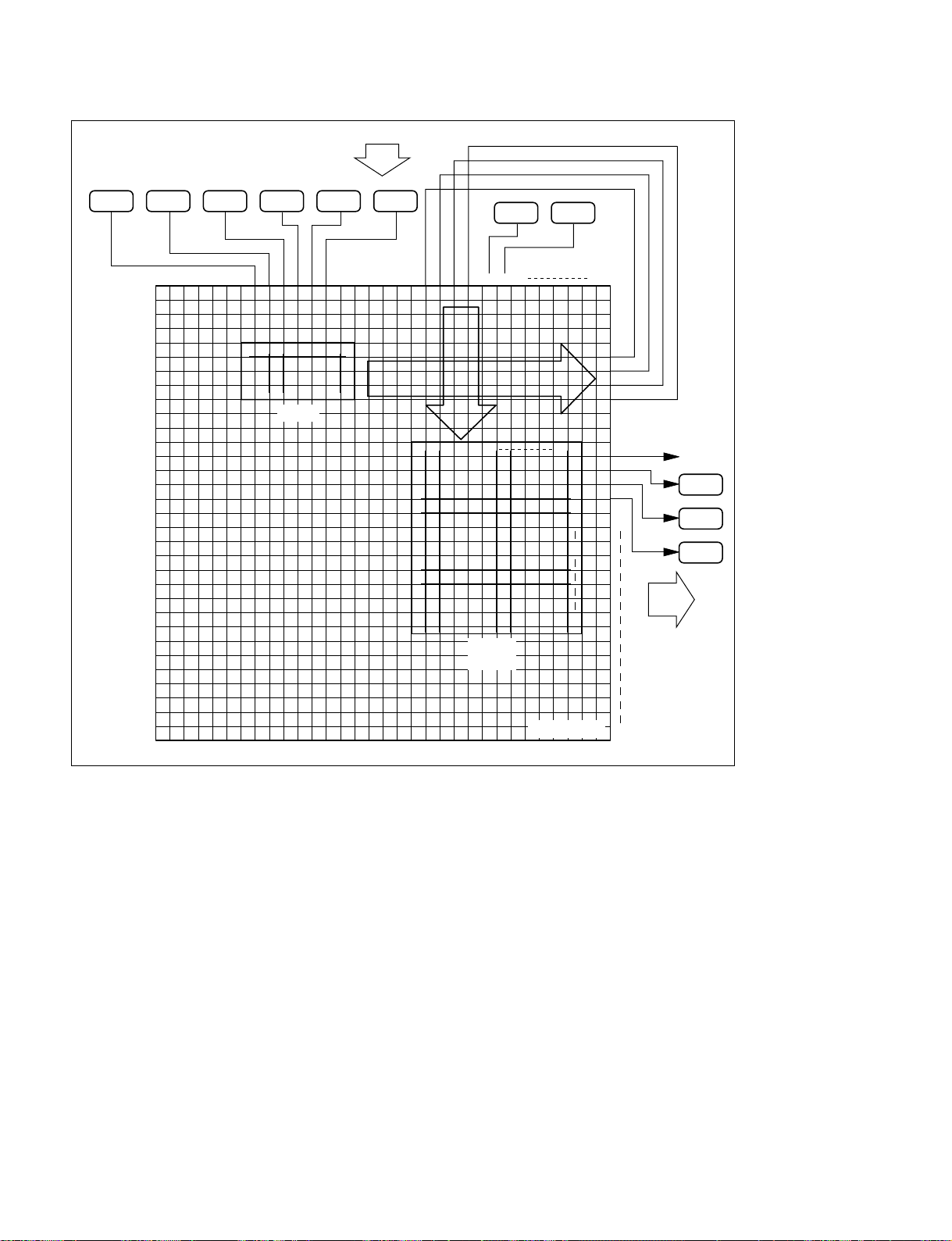
3-7. Tally Setup
Input
CAM1 CAM2 CAM3 CAM4
1 2 3 4 5 6 7 8 9 10 1112131415 161718
1234567
Router
CAM5 CAM6
1
2
3
4
VTR1 VTR2
1920 212223 242526
123456
MVS
(SWR1)
127
1
2
3
4
5
6
~
128
1024
10
11
12
13
14
15
16
17
1
2
3
4
5
6
7
8
9
On Air
VTR3
VTR4
VTR5
Output
Setting the crosspoints connections (wiring)
Virtual matrix
1024
3-28
MVS-8000 System
SYSTEM SETUP
Page 85
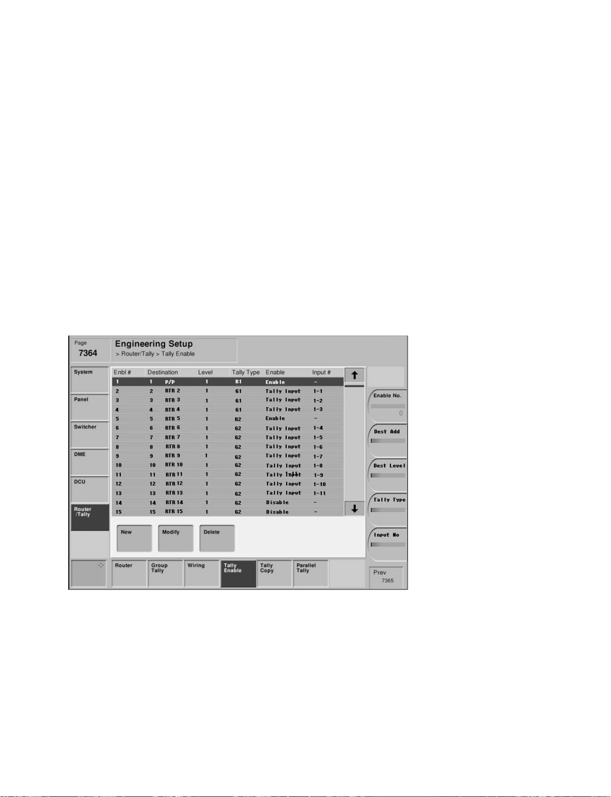
3-7-4. Setting Tally Enable
Engineering Setup → Router/Tally → Tally Enable
Page 7364
This menu is used to set which Destination should be output to which tally.
In the video switching systems, there are many occasions that two or more independent jobs are carried
out by the same switching system.
For example, recording of the on-air program by VTR or by slow motion VTR while on-air is under way
or distributing the on-air program to the local network stations while on-air is under way is performed.
As the result, sophisticated tally system is required in order to correspond to the sophisticated output
system.
If a video switching system becomes sophisticated, the tally system that aims at attracting attention of
operators can become the cause of confusion on the other hand. In order to avoid this confusion, the entire
tally system can be divided into the two systems. After the entire tally system is divided into the two
systems, one tally system can be, for example, assigned to the on-air tally while the other tally system can
be assigned to the off-air live tally. The two colors of red and green can be used for the display of each
tally system.
3-7. Tally Setup
MVS-8000 System
SYSTEM SETUP
Menu screen
3-29
Page 86

3-7. Tally Setup
Setting items
System
Tally Enable Setting is required Setting is not required Setting is required
Tally Type :G1 to 8, R1 to 8 Tally Type :G1 to 8, R1 to 8
Enable : Enable, Disable, Enable : Enable, Disable,
11
1 System
11
Tally Input Tally Input
22
2 System
22
3
33
33
Tally type : Enable → Tally is created all the time.
Disable → Tally is not created all the time.
Tally Input → Tally is created depending on the tally input status.
Input # : It selects which port shall be used when the Tally Input selected.
It also selects which of either DCU1 or DCU2 is going to be used.
The port number in the range of 1 to 102 can be selected.
Setting example : When No. 2 port of DCU1 is going to be used.
Input # 1-2
For the system
11
1
11
Set the tally type and the output conditions of the MVS-8000 outputs (virtual terminal numbers) that you
want to display the tally.
For the system
22
2
22
Because this system does not use tally, the setting is not necessary.
For the system
33
3
33
Set the tally type and the output conditions of the MVS-8000 outputs (virtual terminal numbers) that you
want to display the tally.
Setup example : For the system
33
3
33
System : MVS-8000 x 1 unit, router x 1 unit (8 x 4)
1. When P/P PGM is assigned to 1 using the menu Page 7333 Engineering Setup → Switcher →
Output, OUTPUT 1 (virtual No. 12) of the MVS-8000 becomes the final output of P/P PGM. Put the
red tally to the source of the crosspoints that are connected to this Destination. Select Enable in order
to turn ON the tally at all times.
2. When Outputs 2 and 3 (virtual No. 13 and 14 ) of the MVS-8000 are output to VTR for the simultaneous recording of the on-air program with VTR or for the recording with slow motion VTR, put the
green tally to the source of the crosspoints that are connected to this Destination. Set the Enable item
so that tally turns on only when VTR is going to be used as the output. In this case, set the tally
Enable so that tally turns on only when the Tally GPI In of the DCU receives a signal (when it is on)
from the Tally/GPI Output of VTR.
Page 7363
Enbl# Destination Level Tally Type Enable Input#
1 12 P/P 1 R1 Enable
2 13 AUX1 1 G1 Tally Input 1-1
3 14 AUX2 1 G1 Tally Input 1-2
4 15 AUX3 1 G1 Tally Input 1-3
3-30
MVS-8000 System
SYSTEM SETUP
Page 87
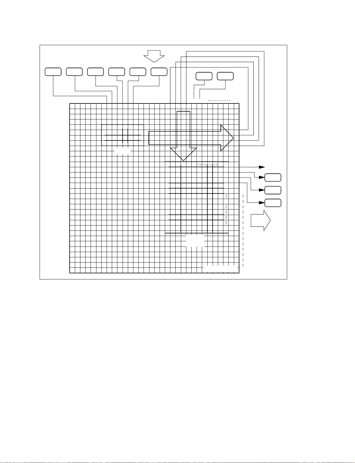
Input
3-7. Tally Setup
CAM1 CAM2 CAM3 CAM4
1 2 3 4 5 6 7 8 9101112131415161718
1234567
Router
CAM5 CAM6
1
2
3
4
VTR1 VTR2
1920 212223 242526
123456
MVS
(SWR1)
127
1
2
3
4
5
6
~
128
1024
10
11
12
13
14
15
16
17
1
2
3
4
5
6
7
8
9
On Air
VTR3
VTR4
VTR5
Output
Setting Tally Enable
Virtual matrix
1024
MVS-8000 System
SYSTEM SETUP
3-31
Page 88
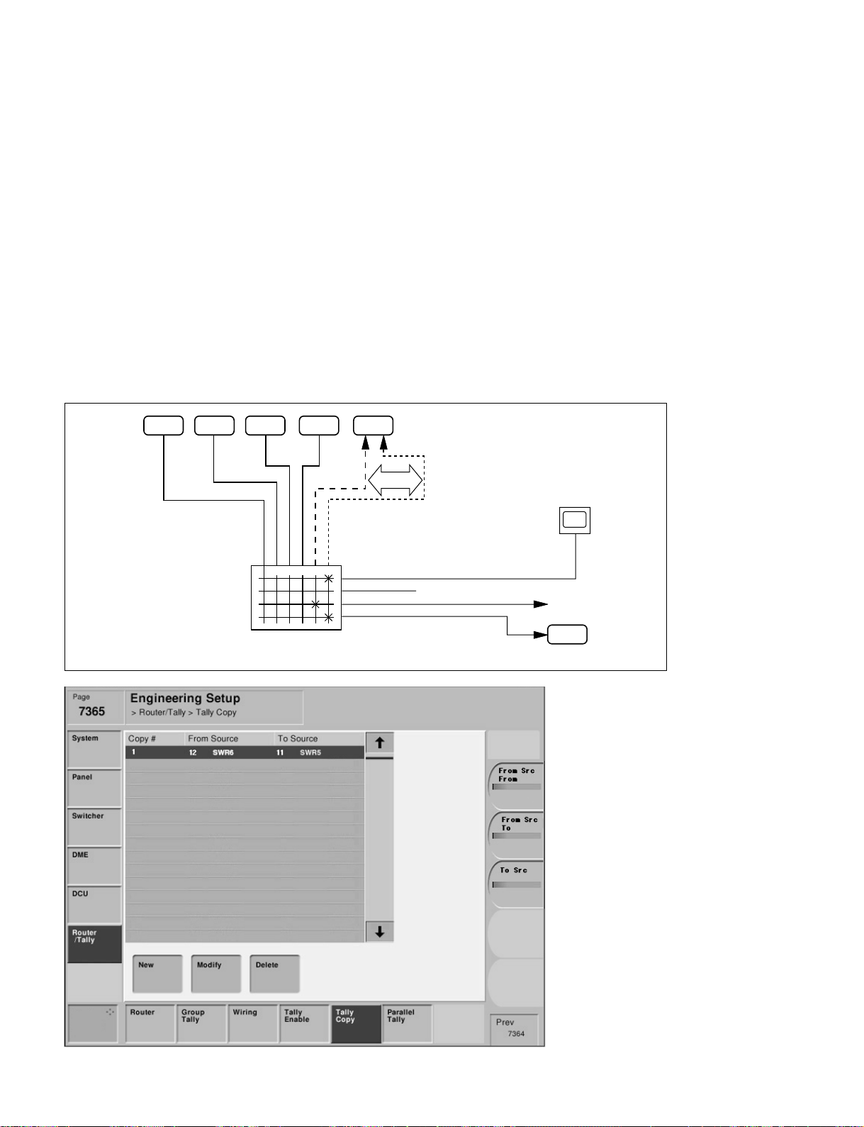
3-7. Tally Setup
3-7-5. Setting Tally Copy
Engineering Setup → Router/Tally → Tally Copy
Page 7365
This menu is used to unify the tally information.
The virtual sources correspond to sources by one-to-one correspondence. However, there are cases that
the same source is connected to two or more input terminals at the same time.
For example, the ordinary video output signal and the video output signal with timecode from a single
unit of VTR are connected to the separate input terminals respectively.
Because the different tally informations that are searched separately can be created for a single unit of
equipment in such a case, these informations must be unified by obtaining the logical OR of the tally
informations corresponding to all virtual input terminals to which the equipments that have the two or
more outputs are connected.
For this purpose, unify the tally informations by this setting that is separate from the equipment connection information.
CAM1 CAM2 CAM3 VTR1
123456
MVS
(switcher)
Without
TC
1
2
3
4
VTR2
With TC
Unifications
Monitor
On Air
VTR3
3-32
Menu screen
MVS-8000 System
SYSTEM SETUP
Page 89

Setting items
3-7. Tally Setup
System
Tally Copy Setting is required Setting is not required Setting is required
For the system
11
1
11
11
1 System
11
22
2 System
22
33
3
33
Set the virtual terminal number of copy source (From Source) and copy destination (To Source) as
required.
For the system
22
2
22
Because there is no equipment that is connected on matrix in this system, this setting is not necessary.
For the system
33
3
33
Set the virtual terminal number of copy source (From Source) and copy destination (To Source) as
required.
Setup example : For the system
33
3
33
System: MVS-8000 x 1 unit, router x 1 unit (8 x 4)
1. Connect the video signal (with TC) from VTR to Primary 8 (virtual terminal No. 26) of the switcher.
2. Connect the video signal (without TC) from VTR to Primary 7 (virtual terminal No. 25) of the
switcher.
Establish the Tally Copy setup because the tally information must be output after the tally informations
from the two sources are unified to a single tally information.
Page 7365
Copy# From Source To Source
1 26 SWR8 25 SWR7
MVS-8000 System
SYSTEM SETUP
3-33
Page 90
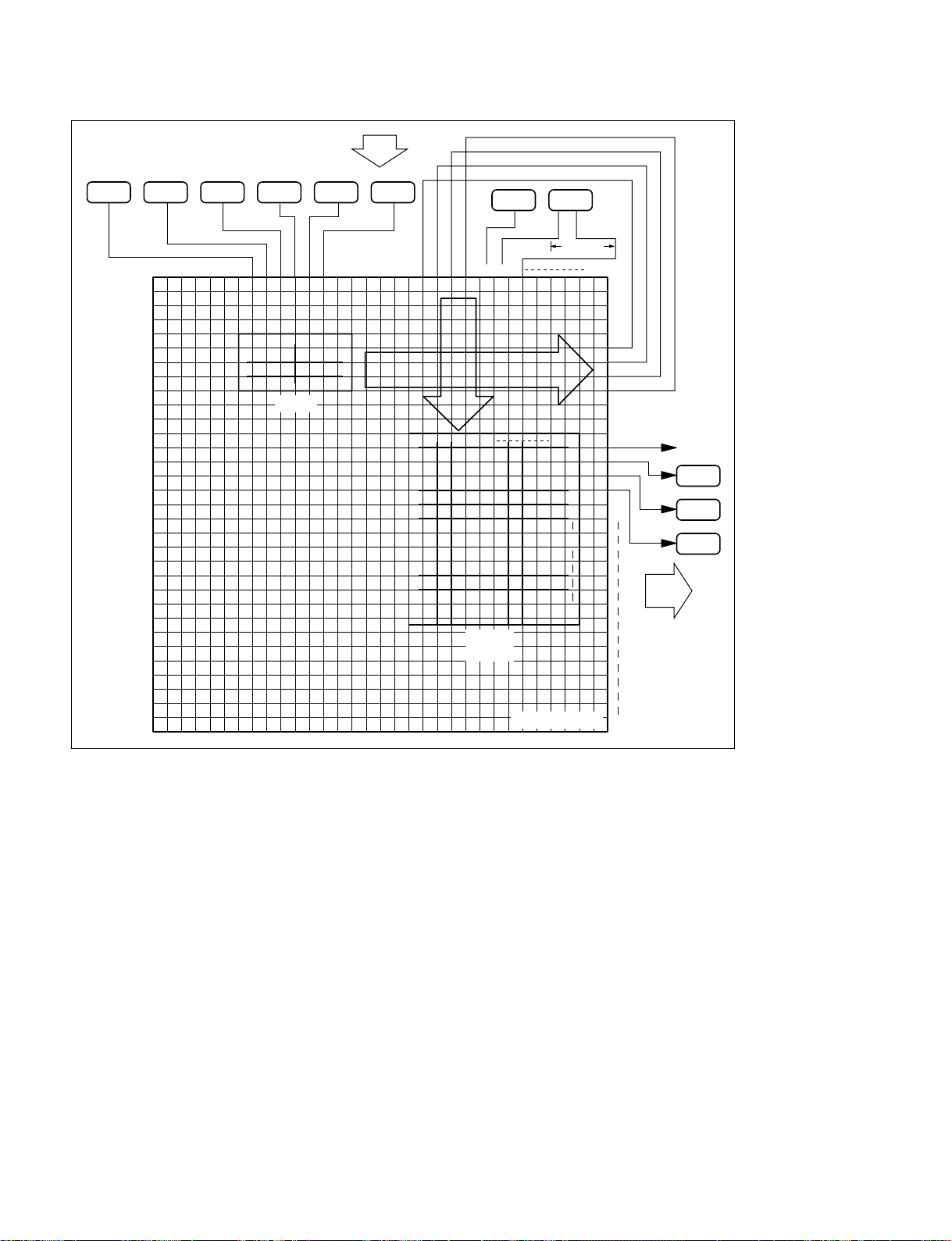
3-7. Tally Setup
Input
CAM1 CAM2 CAM3 CAM4
1 2 3 4 5 6 7 8 9 10 111213141516 1718
1234567
Router
CAM5 CAM6
1
2
3
4
VTR1 VTR2
Without
1920 212223 242526
TC
123456
MVS
(SWR1)
Unifications
1
127
2
3
4
5
6
~
128
With
TC
1024
10
11
12
13
14
15
16
17
1
2
3
4
5
6
7
8
9
On Air
VTR3
VTR4
VTR5
Output
System connection diagram (example)
Virtual matrix
1024
3-34
MVS-8000 System
SYSTEM SETUP
Page 91
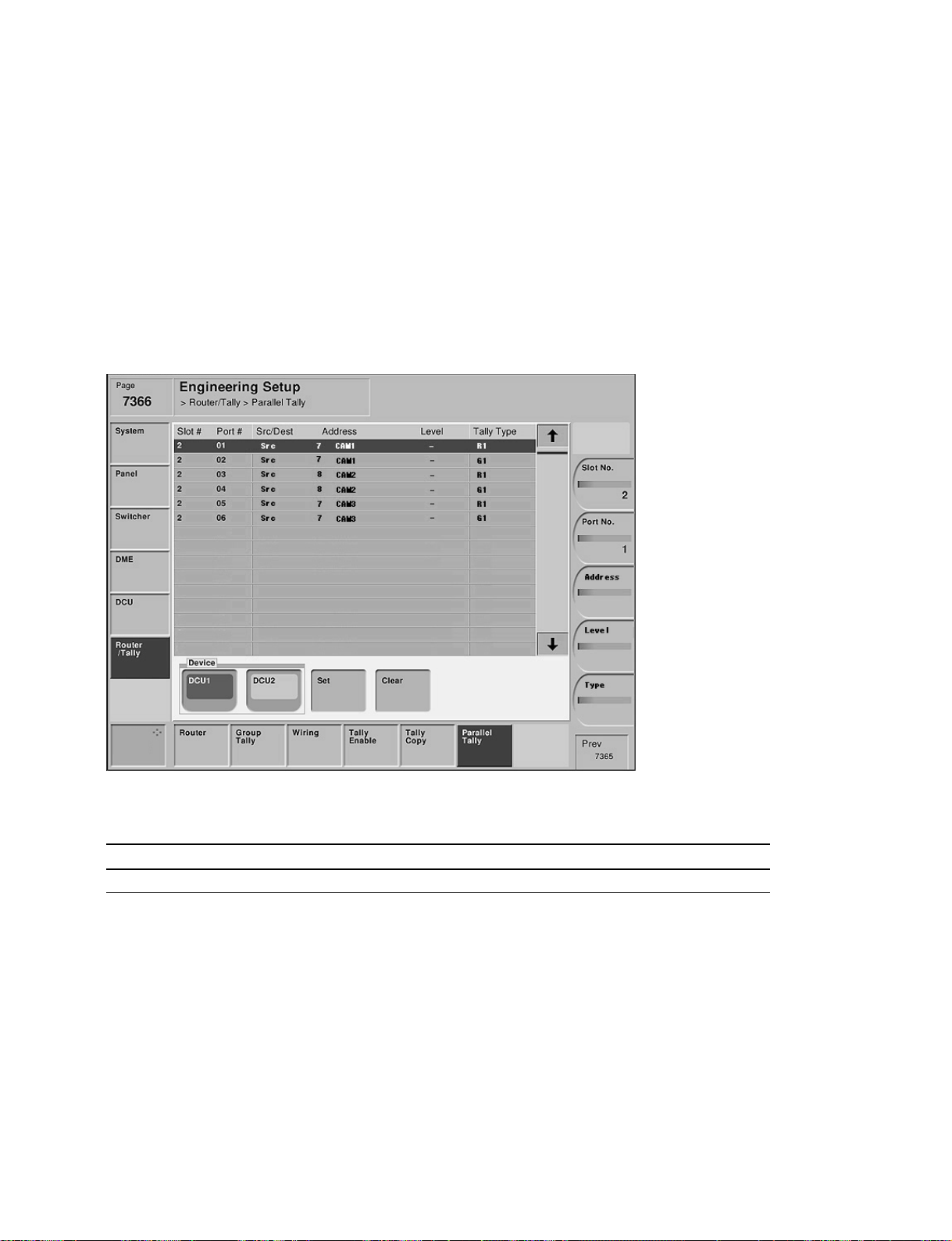
3-7. Tally Setup
3-7-6. Setting Parallel Tally
Engineering Setup → Router/Tally → Parallel Tally
Page 7366
The Parallel Tally output provides the relay contact. This menu is used to enable the Parallel Tally to directly turn
ON/OFF the tally lamp. In this setting, terminal numbers of the virtual inputs and the virtual outputs (Monitor
Tally) of the virtual matrix are assigned to the respective pins of the parallel tally connector (DCU-8000).
m
. To use the Parallel Tally, the Tally/GPI Output Board MKS-8701 must be installed in the MKS-8700.
. Assign the terminal numbers of the virtual inputs and the virtual outputs of the virtual matrix to the slot
numbers and the port number of the slot in which the MKS-8701 is installed.
Menu screen
Setting items
System
Parallel Tally Setting is required Setting is not required Setting is required
11
1 System
11
22
2 System
22
33
3
33
Device : Selects either DCU1 or DCU2.
Slot No. : Slot number of the MKS-8701 that is inserted in the DCU-8000.
Port No. : Port number of the MKS-8701.
For the system
11
1
11
Set the Tally Type and assign the virtual terminal number to each pin (pin number and slot number of the
MKS-8701) of the parallel tally.
For the system
22
2
22
This setting is not required for the system 2 because the system 2 does not use tally.
For the system
33
3
33
Set the Tally Type and assign the virtual terminal number to each pin (pin number and slot number of the
MKS-8701) of the parallel tally.
MVS-8000 System
SYSTEM SETUP
3-35
Page 92
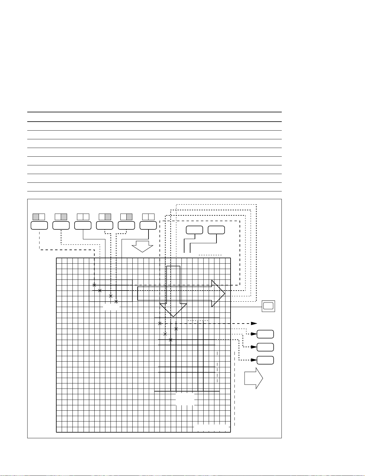
3-7. Tally Setup
Setup example : For the system
33
3
33
System : MVS-8000 x 1 unit, router x 1 unit (8 x 4)
1. Put the Red/Green Tally to the CAM 1 to CAM 3 (virtual terminals Nos. 7 to 9) that supply video
signal to the router.
2. Put the Red/Green Tally to the monitor that is connected to Destination 5 (virtual terminal No. 9) of
the router.
Page 7366
Slot# Port# Src/Dest Address Level Tally Type
2 01 Src 7 CAM1 _ R1
2 02 Src 7 CAM1 _ G1
2 03 Src 8 CAM2 _ R1
2 04 Src 8 CAM2 _ G1
2 05 Src 9 CAM3 _ R1
2 06 Src 9 CAM3 _ G1
2 07 Dest 9 MON1 1 R1
2 07 Dest 9 MON1 1 G1
R G R G R G R G R GR G
CAM1
CAM2 CAM3 CAM4
CAM5 CAM6
VTR1 VTR2
Input
1 2 3 4 5 6 7 8 9 10 111213141516 1718
1234567
Router
1
2
3
4
1920 212223 242526
123456
MVS
(SWR1)
127
1
2
3
4
5
6
~
128
1024
10
11
12
13
14
15
16
17
1
2
3
4
5
6
7
8
9
Monitor
On Air
VTR3
VTR4
VTR5
Output
3-36
System connection diagram (example)
Virtual matrix
1024
MVS-8000 System
SYSTEM SETUP
Page 93

3-7. Tally Setup
3-7-7. Setting Serial Tally
The Serial Tally signal is output from the Serial Tally 1 terminal and the Serial Tally 2 terminal of the MKS-8700.
Ver. 1.20 does not support the Serial Tally setup. The fixed tally output is supported.
In Ver. 1.20, the fixed tallies of R-1, G-1, R-2 and G-2 are output from Serial Tally 1 terminal of the MKS-8700.
Tally signal is output according to the protocol attached as APPENDIX. For details, please refer to the “BVS-3000 Series,
DVS-8000 Series PROTOCOL and COMMAND SPECIFICATIONS (Sony Part No. : 9-967-262-21)”.
Bit assignment is shown in the following table.
MVS-8000 Matrix assignment
Bit No. Source
1 Primary 1
2 Primary 2
3 Primary 3
4 Primary 4
5 Primary 5
6 Primary 6
7 Primary 7
8 Primary 8
9 Primary 9
10 Primary 10
11 Primary 11
12 Primary 12
13 Primary 13
14 Primary 14
15 Primary 15
16 Primary 16
17 Primary 17
18 Primary 18
19 Primary 19
20 Primary 20
21 Primary 21
22 Primary 22
23 Primary 23
24 Primary 24
25 Primary 25
26 Primary 26
27 Primary 27
28 Primary 28
29 Primary 29
30 Primary 30
31 Primary 31
32 Primary 32
33 Primary 33
34 Primary 34
35 Primary 35
Bit No. Source
36 Primary 36
37 Primary 37
38 Primary 38
39 Primary 39
40 Primary 40
41 Primary 41
42 Primary 42
43 Primary 43
44 Primary 44
45 Primary 45
46 Primary 46
47 Primary 47
48 Primary 48
49 Primary 49
50 Primary 50
51 Primary 51
52 Primary 52
53 Primary 53
54 Primary 54
55 Primary 55
56 Primary 56
57 Primary 57
58 Primary 58
59 Primary 59
60 Primary 60
61 Primary 61
62 Primary 62
63 Primary 63
64 Primary 64
65 Primary 65
66 Primary 66
67 Primary 67
68 Primary 68
69 Primary 69
70 Primary 70
MVS-8000 System
SYSTEM SETUP
3-37
Page 94

3-7. Tally Setup
Bit No. Source
71 Primary 71
72 Primary 72
73 Primary 73
74 Primary 74
75 Primary 75
76 Primary 76
77 Primary 77
78 Primary 78
79 Primary 79
80 Primary 80
81 Black
82 White
83 Color Bkgd 1
84 Color Bkgd 2
85 Frame Memory 1
86 Frame Memory 2
87 Frame Memory 3
88 Frame Memory 4
89 Frame Memory 5
90 Frame Memory 6
91 Frame Memory 7
92 Frame Memory 8
93 Color Correction 1
94 Color Correction 2
95 DME Monitor Video
96 DME Monitor Key
97 M/E-1 Out 1
98 M/E-1 Out 2
99 M/E-1 Out 3
100 M/E-1 Out 4
101 M/E-1 Out 5
102 M/E-1 Out 6
103 M/E-2 Out 1
104 M/E-2 Out 2
105 M/E-2 Out 3
106 M/E-2 Out 4
107 M/E-2 Out 5
108 M/E-2 Out 6
109 M/E-3 Out 1
110 M/E-3 Out 2
111 M/E-3 Out 3
112 M/E-3 Out 4
113 M/E-3 Out 5
Bit No. Source
114 M/E-3 Out 6
115 P/P Out 1
116 P/P Out 2
117 P/P Out 3
118 P/P Out 4
119 P/P Out 5
120 P/P Out 6
121 DME1
122 DME2
123 DME3
124 DME4
125 DME5
126 DME6
127 DME7
128 DME8
3-38
MVS-8000 System
SYSTEM SETUP
Page 95

APPENDIX
****************
MVS SERIAL TALLY
****************
EFF:EFFECT ADDRESS
24h:SERIAL TALLY
<<PGM TALLY>>
WRITE: BC, EFF, byte2, FF, byte4, byte5, byte6, ...
byte2 TALLY TYPE
91h: GP1 RED
92h: GP1 GREEN
93h: GP2 RED
94h: GP2 GREEN
95h: GP3 RED
96h: GP3 GREEN
97h: GP4 RED
98h: GP4 GREEN
3-7. Tally Setup
* You can set TALLY TYPE in the setup menu.
byte4 COMPRESS STATUS BYTE (UPPER)
byte5 COMPRESS STATUS BYTE (LOWER)
DATA bit 7 6 5 43210
---------------------------------------------------------------------------------------------STATUS(U) bit 7 128 127 126 125 124 123 122 121
6 120 119 118 117 116 115 114 113
5 112 111 110 109 108 107 106 105
4 104 103 102 101 100 99 98 97
3 9695949392919089
2 8887868584838281
1 8079787776757473
0 7271706968676665
---------------------------------------------------------------------------------------------STATUS(L) bit 7 64 63 62 61 60 59 58 57
6 5655545352515049
5 4847464544434241
4 4039383736353433
3 3231302928272625
2 2423222120191817
1 16151413121110 9
0 87654321
MVS-8000 System
SYSTEM SETUP
3-39
Page 96

3-7. Tally Setup
1-128 means each source number. It’s assignable, but the default is the same as MVS source number
specified in COMPACT MODE. If it’s tallied, the bit is “1”. If it’s not tallied, it’s “0”.
Status bit shows if the data is all “0” or not.
If it’s all “0”, the status bit is “0”. If it’s not all “0”, it’s “1”. This is to minimize the data length.
For example:
If only sources #100 and #72 are tallied:
STATUS(U) bit 7: 0
6: 0
5: 0
4: 1
3: 0
2: 0
1: 0
0: 1
Then, the following bytes are only STATUS(U) bit 4 data (97-104) and bit 0 data (65-72) as follows:
byte6 MSB 7: 104
6: 103
5: 102
4: 101
3: 100
2: 99
1: 98
LSB 0: 97
byte7 MSB 7: 72
6: 71
5: 70
4: 69
3: 68
2: 67
1: 66
LSB 0: 65
The serial tally information is sent whenever the status is changed. (There is no READ command.)
3-40
MVS-8000 System
SYSTEM SETUP
Page 97
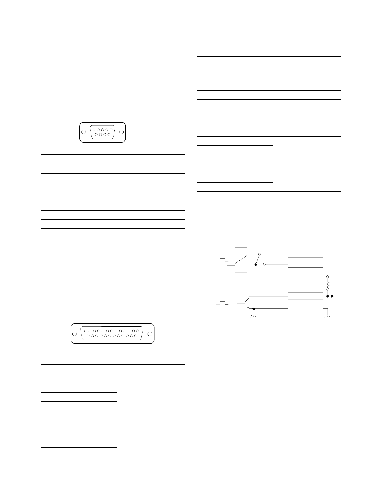
3-8. Pin Output
3-8. Pin Output
3-8-1. MVS-8000
The input/output signals of the connectors at the rear panel
are as follows.
TERMINAL : RS-232C (D-sub 9-pin, Female)
to Terminal
5
_ EXT VIEW _
Pin No. Signal name Function
1 DCD Data Carrier detect
2 RXD Received data
3 TXD Transmitted data
4 DTR Data terminal ready
5 GND Ground
6 DSR Data set ready
7 RTS Request to send
8 CTS Clear to send
9 __
(*1) :Pins 1, 4 and 6 are internally connected together on the CN-2133
board.
(*2) :Pins 7 and 8 are internally connected together on the CN-2133 board.
1
69
(*1)
(*1)
(*1)
(*2)
(*2)
Pin No. Signal name Function
11 GPI OUT 6 General-purpose relay
12 GPI OUT 8
output (B)
(*4)
13 GPI OUT COM Ground for open collector
output
14 GND Ground
15 GPI IN 1 General-purpose input
16 GPI IN 3
17 GPI IN 5
18 GPI IN 7
19 GPI OUT 1A General-purpose relay
20 GPI OUT 2A
output (A)
(*3)
21 GPI OUT 3A
22 GPI OUT 4A
23 GPI OUT 5 General-purpose open
24 GPI OUT 7
collector output
(*4)
25 GPI OUT COM Ground for open collector
output
n
A and B of the same number constitute a pair of relay
contacts.
(*3)
<Relay>
GPI OUT x B
GPI OUT x A
x : 1-4
+V
GPI : (D-sub 25-pin, Female)
INPUT x 8, TTL
OUTPUT x 4, relay contacts 30 V 0.1 A
(resistive load)
OUTPUT x 4, open collector, 30 V rated voltage
13
25
EXT VIEW
Pin No. Signal name Function
1 GND Ground
2 GND Ground
3 GPI IN 2 General-purpose input
4 GPI IN 4
5 GPI IN 6
6 GPI IN 8
7 GPI OUT 1B General-purpose open
8 GPI OUT 2B
collector output (B)
9 GPI OUT 3B
10 GPI OUT 4B
1
14
(*3)
(*4)
<Open collector output>
GPI OUT 5-8
GPI OUT COM
MVS-8000 System
SYSTEM SETUP
3-41
Page 98

3-8. Pin Output
REMOTE 1 to 4 : RS-422A (D-sub 9-pin, Female)
<DEVICE> (*5) from External Devices
5
1
69
_ EXT VIEW _
Pin No. Signal name Function
1 FG Frame ground
2TX_ Transmitted data (_)
3RX+ Received data (+)
4 GND Common ground
5 _ No Connection
6 GND Common ground
7TX+ Transmitted data (+)
8RX_ Received data (_)
9 _ No Connection
(*5) <DEVICE> : The equipment that is in charge of control
DATA/CTRL : 100BASE-TX, RJ-45 (8-pin)
1
8
_ EXT VIEW _
Pin No. Signal name Function
1TX+ Transmitted data (+)
2TX_ Transmitted data (_)
3RX+ Received data (+)
4 _ No Connection
5 _ No Connection
6RX_ Received data (_)
7 _ No Connection
8 _ No Connection
3-42
MVS-8000 System
SYSTEM SETUP
Page 99

3-8. Pin Output
<Relay>
GPI OUT x B
GPI OUT 5-8
GPI OUT COM
<Open collector output>
x;1-4
+V
GPI OUT x A
(*2)
(*3)
3-8-2. MVE-8000
The input/output signals of the connectors at the rear panel
are as follows.
n
<CONTROLLER> indicates a controlling device.
<DEVICE> indicates a controlled device.
EDITOR : RS-422A (D-sub 9-pin, Female)
<DEVICE> (*1)
5
_ EXT VIEW _
Pin No. Signal name Function
1 FG Frame ground
2TX_ Transmitted data (_)
3RX+ Received data (+)
4 GND Ground
5 _ No Connection
6 GND Ground
7TX+ Transmitted data (+)
8RX_ Received data (_)
9 FG Frame ground
(*1) : Editing control unit such as BVE-9100 (EDITOR)
DATA
CTRL : 100BASE-TX, RJ-45 (8-pin)
1
_ EXT VIEW _
Pin No. Signal name Function
1TX+ Transmitted data (+)
2TX_ Transmitted data (_)
3RX+ Received data (+)
4 _ No Connection
5 _ No Connection
6RX_ Received data (_)
7 _ No Connection
8 _ No Connection
1
69
8
GPI : (D-sub 25-pin, Female)
INPUT x 8, TTL
OUTPUT x 4, relay contacts 30 V 0.1 A
(resistive load)
OUTPUT x 4, open collector 30 V rated voltage
113
25 14
_EXT VIEW_
Pin No. Signal name Function
1 GND Ground
2 GND Ground
3 GPI IN 2 General-purpose input
4 GPI IN 4
5 GPI IN 6
6 GPI IN 8
7 GPI OUT 1B General-purpose relay output (B)
*2
8 GPI OUT 2B
9 GPI OUT 3B
10 GPI OUT 4B
11 GPI OUT 6 General-purpose open collector
12 GPI OUT 8 output
*3
13 GPI OUT COM Ground for open collector output
14 GND Ground
15 GPI IN 1 General-purpose input
16 GPI IN 3
17 GPI IN 5
18 GPI IN 7
19 GPI OUT 1A General-purpose relay output (A)
*2
20 GPI OUT 2A
21 GPI OUT 3A
22 GPI OUT 4A
23 GPI OUT 5 General-purpose open collector
24 GPI OUT 7 output
*3
25 GPI OUT COM Ground for open collector output
n
A and B of the same number constitute a pair of relay contacts.
MVS-8000 System
SYSTEM SETUP
3-43
Page 100
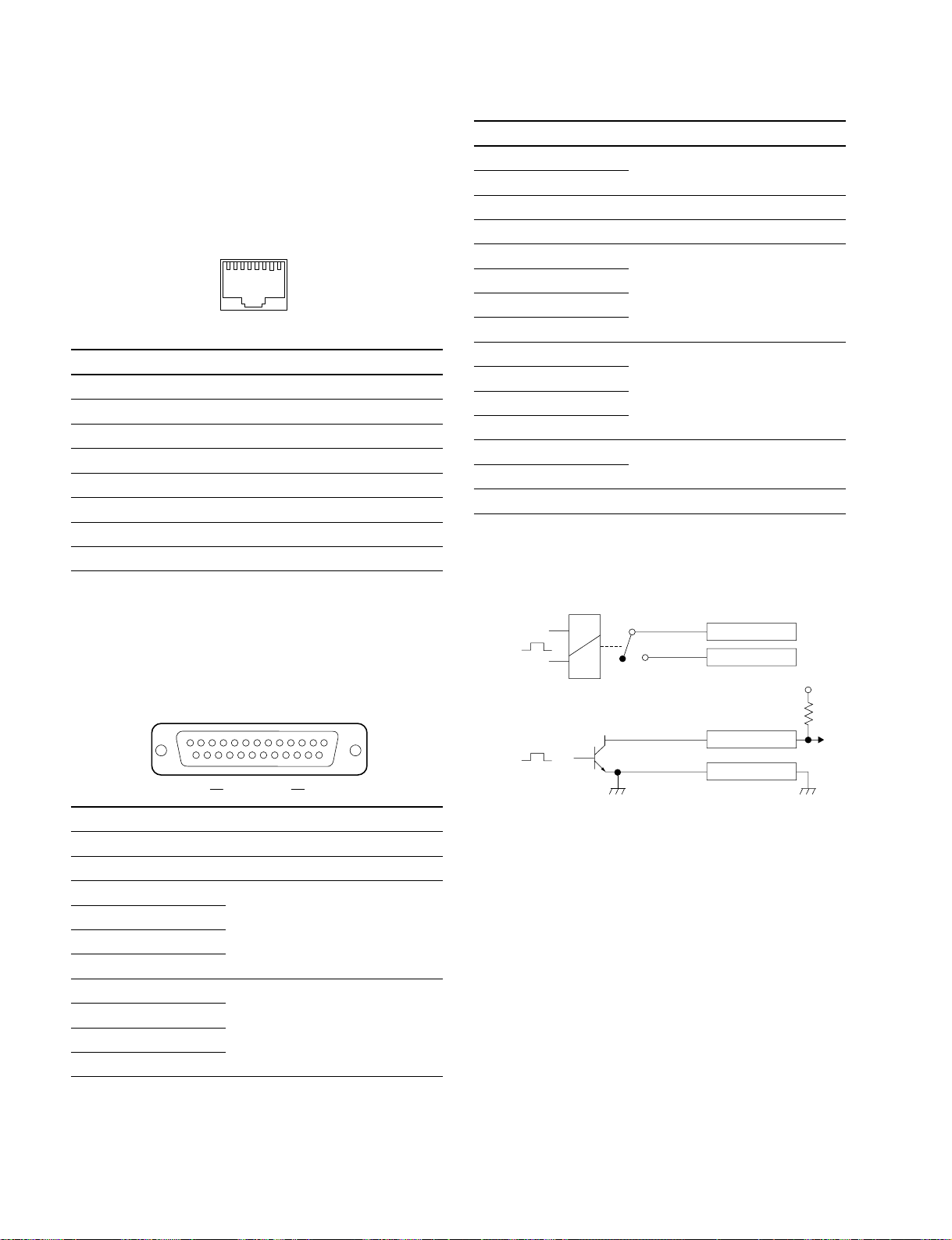
3-8. Pin Output
3-8-3. CCP-8000
Input and output signals of the connectors on the rear panel
are as follows.
CTRL/DATA/PERIPH : 100BASE-TX, RJ-45 (8-pin)
1
_ EXT VIEW _
Pin No. Signal name Function
1TX+ Transmitted data (+)
2TX_ Transmitted data (_)
3RX+ Received data (+)
4 _ No Connection
5 _ No Connection
6RX_ Received data (_)
7 _ No Connection
8 _ No Connection
8
Pin No. Signal name Function
11 GPI OUT 6 General-purpose open collector
12 GPI OUT 8
output (B)
(*2)
13 GPI OUT COM Ground for open collector output
14 GND Ground
15 GPI IN 1 General-purpose input
16 GPI IN 3
17 GPI IN 5
18 GPI IN 7
19 GPI OUT 1A General-purpose relay output (A)
20 GPI OUT 2A
21 GPI OUT 3A
22 GPI OUT 4A
23 GPI OUT 5 General-purpose open collector
(*2)
24 GPI OUT 7
output
25 GPI OUT COM Ground for open collector output
n
A and B of the same number constitute a pair of relay
contacts.
(*1)
GPI : (D-sub 25-pin, Female)
INPUT x 8, TTL
OUTPUT x 4, relay contacts 30 V 0.1 A
(resistive load)
OUTPUT x 4, open collector 30 V rated voltage
13
25
EXT VIEW
Pin No. Signal name Function
1 GND Ground
2 GND Ground
3 GPI IN 2 General-purpose input
4 GPI IN 4
5 GPI IN 6
6 GPI IN 8
7 GPI OUT 1B General-purpose relay
8 GPI OUT 2B output (B)
9 GPI OUT 3B
10 GPI OUT 4B
1
14
(*1)
<Relay>
(*1)
<Open collector output>
(*2)
GPI OUT x B
GPI OUT x A
x : 1-4
GPI OUT 5-8
GPI OUT COM
+V
3-44
MVS-8000 System
SYSTEM SETUP
 Loading...