

Sony CBK-VF01 Operation Manual
Sony Corporation
CBK-VF01
(SYM)
4-265-156-01(1)
Printed in Japan
2011.01 32
©2011
HD ELECTRONIC VIEWFINDER
CBK-VF01
電気製品は、安全のための注意事項を守らないと、
火災や人身事故になることがあります。
このオペレーションマニュアルには、事故を防ぐための重要な注意事項と製品の取り扱いか
たを示してあります。このオペレーションマニュアルをよくお読みのうえ、製品を安全にお
使いください。お読みになったあとは、いつでも見られるところに必ず保管してください。
OPERATION MANUAL
[Japanese/English/French/German/Italian/Spanish/Chinese]
1st Edition
日本語
安全のために
電気製品は、安全のための注意事項を守らないと、火災や感電
などにより死亡や大けがなど人身事故につながることがあり、
危険です。
事故を防ぐために次のことを必ずお守りください。
安全のための注意事項を守る
4ページの注意事項をよくお読みください。
定期点検をする
長期間安全に使用していただくために、定期点検を実施するこ
とをおすすめします。点検の内容や費用については、ソニーの
サービス担当者または営業担当者にご相談ください。
故障したら使用を中止する
ソニーのサービス担当者、または営業担当者にご連絡ください。
万一、異常が起きたら
• 異常な音、におい、煙が出たら
m
1 カメラの電源を切る。
2 接続コードを抜く。
3 ソニーのサービス担当者、または営業担当者に修理を依頼
する。
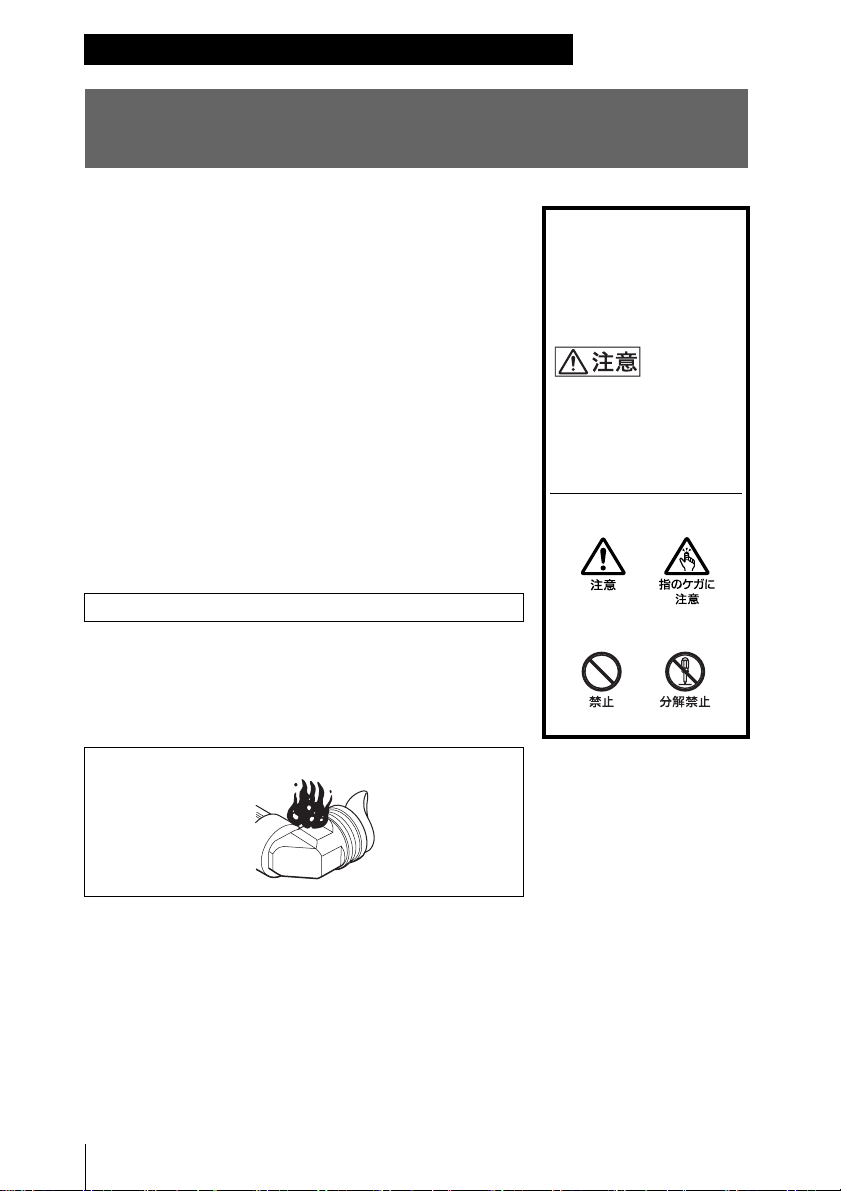
炎が出たら
警告表示の意味
オペレーションマニュアルお
よび製品では、次のような表
示をしています。表示の内容
をよく理解してから本文をお
読みください。
この表示の注意事項を守らな
いと、感電やその他の事故に
よりけがをしたり周辺の物品
に損害を与えたりすることが
あります。
注意を促す記号
行為を禁止する記号
m
すぐにカメラの電源を切り、消火する。
安全のために
2
目次
注意 ...................................................................................................... 4
概要 ................................................................................................. 5
使用上のご注意 ................................................................................ 5
各部の名称と働き ............................................................................ 6
カメラに取り付ける ......................................................................... 8
位置を調整する ...........................................................................8
角度を調整する ...........................................................................9
視度と画面を調整する ..................................................................... 9
VF
筒部/アイピース部を跳ね上げる ............................................ 10
画面や内部(LCD 画面)をクリーニングする ............................... 12
仕様 ............................................................................................... 12
JP
目次
3
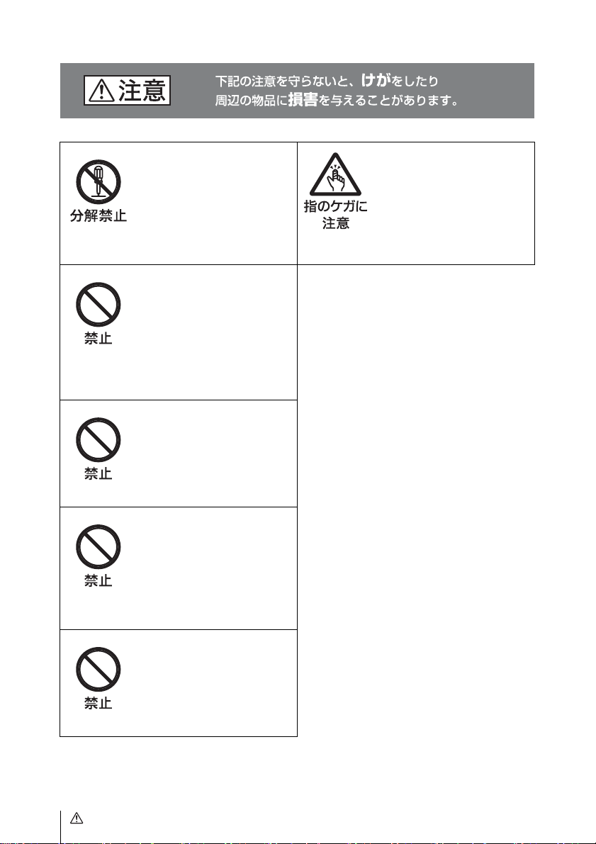
分解しない、改造しない
分解したり、改造したりする
と、感電の原因となります。
ビューファインダー内部の調整
や点検を行う必要がある場合
は、必ずソニーのサービス担当
者にご依頼ください。
内部に水や異物を入れない
水や異物が入ると火災の原因と
なります。
万一、水や異物が入ったとき
は、すぐにカメラの電源を切
り、接続コードを抜いて、ソ
ニーのサービス担当者または営
業担当者にご相談ください。
油煙、湯気、湿気、ほこ
りの多い場所では設置
• 使
用しない
上記のような場所で設置・使用
すると、火災や感電の原因とな
ります。
ビューファインダーの接
眼レンズを太陽に向けて
放置しない
太陽光が接眼レンズを通して
ビューファインダー内部に焦点
を結び、火災の原因となること
があります。
ビューファインダーを回
転するときには手や指を
挟まない
ビューファインダーを回転する
とき、本体と
手や指を挟み、けがの原因とな
ることがあります。
VF アームの間に
太陽や輝度の高い光源に
レンズを向けてアイピー
スを覗かない
太陽や輝度の高い光源にレンズ
を向けてアイピースを覗くと、
目を痛める原因になります。
4
注意

概要 使用上のご注意
HDエレクトロニックビューファインダー
CBK-VF01は、3.5型LCDカラービューファ
インダーです。
本機には以下のような特長があります。
高解像度・広視覚野
高精細LCDの採用により、水平解像度
500TV本以上の高解像度を実現しています。
大画面
LCD搭載により、アイピースをはず
した状態での快適な撮影が可能です。
安定した画像
LCD画面では、画面の明るさが変化しても
ひずみに影響しないため安定した画像が得
られます。
高性能ルーペ
非球面を含む2群3枚構成レンズを使用して
いるため、ひずみや画ゆれの少ない画像が
得られると同時に、広範囲の視度調整が可
能です。
跳ね上げ、着脱可能なアイピース部
アイピース部を跳ね上げ、または取りはず
すことにより、目を離して撮影を行うこと
ができます。
跳ね上げ、着脱可能なVF筒部・それに
対応した半透過型
VF筒部を跳ね上げ、または取りはずすこと
により、
うことができます。
半透過型
画像を見ることができます。
LCD画面を直接見ながら作業を行
LCDにより周囲環境に関係なく、
LCD
使用場所について
気温の低い場所で使用すると、電源投入直
後、動解像度が低下します。
LCD(液晶)パネルの輝点・滅点
について
本機のLCD(液晶)パネルは有効画素
99.99% 以上の非常に精密度の高い技術で
作られていますが、画面上に黒い点が現れ
たり(画素欠け)、常時点灯している輝点
(赤、青、緑など)や滅点がある場合があり
ます。また、
長期間ご使用の間に画素欠けが生じること
もあります。これらの現象は故障ではあり
ませんので、ご了承の上本機をお使いくだ
さい。なお、これらの点が記録されること
はありません。
LCD(液晶)パネルの特性上、
LCD画面の表示について
LCDパネルの特性上、長期間ご使用の間に
輝度が下がり、色温度が変化することがあ
ります。これらの現象は故障ではありませ
んので、ご了承の上本機をお使いください。
なお、これらの現象が記録に影響すること
はありません。
概要 / 使用上のご注意
5
接眼レンズについて
本機の接眼レンズを太陽などの強い光に向
けないでください。
太陽光などの強い光がレンズによって集光
することにより、
の原因になるおそれがあります。
LCDパネルの焼損や火災
お手入れについて
• 画面の表面からほこりを取り除くときは、
ブロアーを使用してください。
• 画面をクリーニングするときは、シン
ナーなどの溶剤はいっさい使用しないで
ください。
各部の名称と働き
各部の名称と働き
6
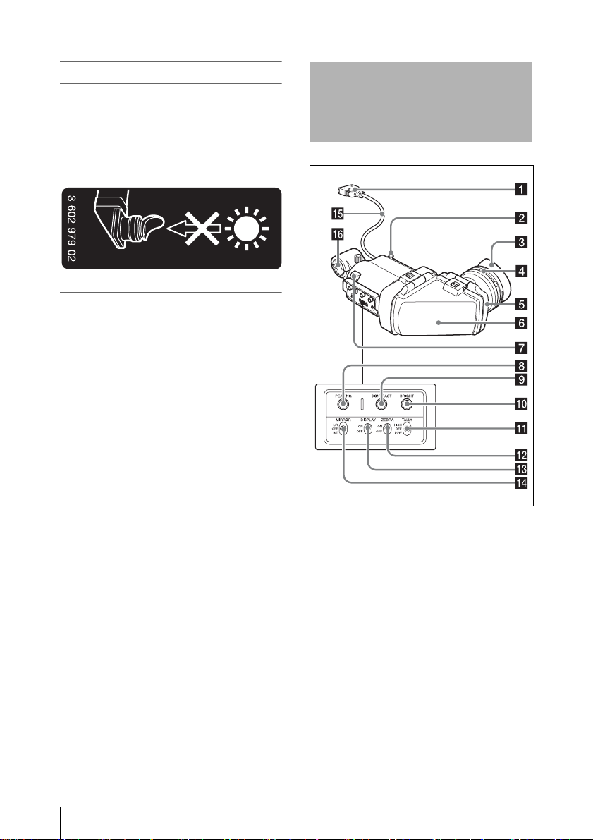
a コネクター
カメラの
b スライドストッパー
本機をカメラに取り付けて左右にスライド
させるとき、本機がカメラからはずれるの
を防ぎます。
c アイカップ
d 視度調整リング
画面の映像が最もはっきり見えるように、
このリングを回して視度を調整します。
e アイピース部
使用状況に応じて、跳ね上げたり、取りは
ずしたりすることができます。
VF端子(角型)に接続します。

f VF筒部
使用状況に応じて、跳ね上げたり、取りは
ずしたりすることができます。
g タリーランプ
カメラの
ボタン、またはリモートコントロールユ
ニットの
ると点灯します。
異常発生時は、点滅して警告表示を行いま
す。
h
時計方向に回すと、画面の映像の輪郭が強
調され、レンズのフォーカス合わせが容易
になります。カメラの出力信号には影響し
ません。
i
画面のコントラストを調整します。カメラ
の出力信号には影響しません。
j
画面の明るさを調整します。カメラの出力
信号には影響しません。
REC STARTボタン、レンズのVTR
VTRボタンを押して、記録が始ま
PEAKING(ピーキング調整)つまみ
CONTRAST(コントラスト調整)つま
み
BRIGHT(明るさ調整)つまみ
n
MIRROR(反転)スイッチ
VF筒部を跳ね上げたり、回転させたりして
画像が左右または上下に反転しているとき
に使用します。
L/R:画像を左右に反転させる
OFF:画像を反転させない
B/T:画像を上下に反転させる
o ビューファインダーケーブル
p マイクホルダー
k
TALLY(タリー)スイッチ
タリーランプをコントロールします。
HIGH:タリーランプが明るくなる
OFF:タリーランプが機能しなくなる
LOW:タリーランプが暗くなる
l
ZEBRA(ゼブラパターン)スイッチ
ゼブラパターンの表示をコントロールしま
す。
ON:ゼブラパターンを表示する
OFF:ゼブラパターンを表示しない
m
DISPLAY(ディスプレイ)スイッチ
文字情報の表示をコントロールします。
ON:文字情報を表示する
OFF:文字情報を表示しない
各部の名称と働き
7
カメラに取り付ける
ビューファインダーを取り付けたあと、接眼レン
ズを太陽に向けて放置しないでください。
太陽光が接眼レンズを通して焦点を結び、火災の
原因になることがあります。
ご注意
本機を取り付けるときは、以下の点にご注意くだ
さい。
• 必ずカメラの電源をオフにしてから、ビュー
ファインダーコネクターをカメラの
型)に差し込んでください。電源がオンの状態
でコネクターを差し込むと、本機が正常に動作
しないことがあります。
• ビューファインダーコネクターをカメラのVF端
子(角型)の奥まで確実に差し込んでくださ
い。コネクターが確実に接続されていないと、
画像が乱れたり、タリーランプが正常に点灯し
ないことがあります。
VF端子(角
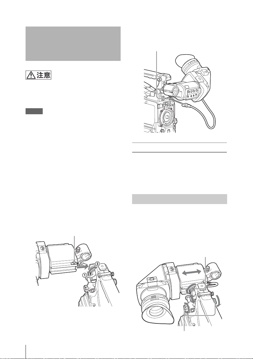
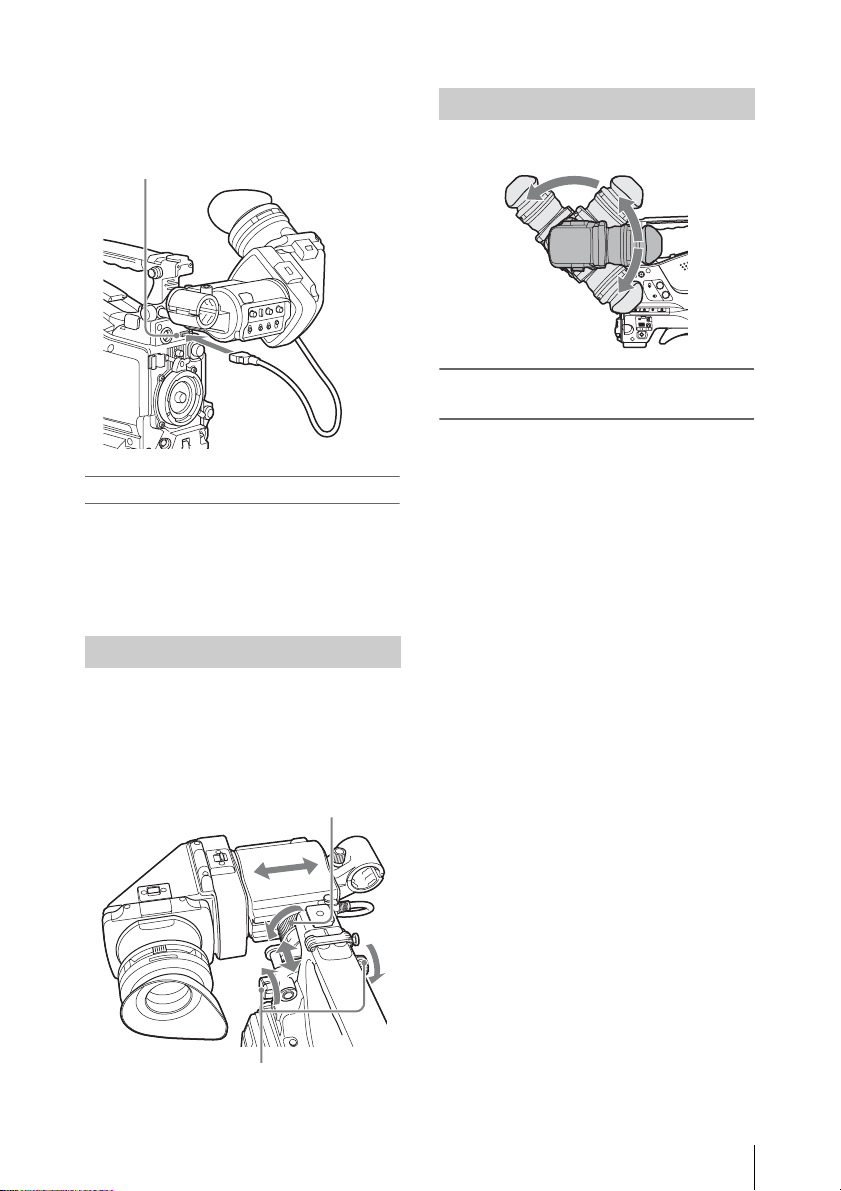
2 ビューファインダーコネクターをカ
VF端子(角型)に接続する。
メラの
VF端子(角型)
取りはずすには
取り付けと逆の手順で行います。ただし、
本機を取り付けシューから取りはずすとき
に、スライドストッパーを引き上げてくだ
さい(手順
1の図参照)。
1 1カメラの左右位置固定リングをゆる
2カメラのビューファインダー
める。
取り付けシューに本機を取り付け、
左右位置固定リングを締める。
スライドストッパー
カメラに取り付ける
8
3
位置を調整する
左右位置を調整するときはカメラのビュー
ファインダー左右位置固定リングを、前後
位置を調整するときはカメラのビューファ
インダー前後位置
れゆるめます。
ビューファインダー左右位置固定リング
ビューファインダー前後位置
LOCKつまみを、それぞ
LOCKつまみ
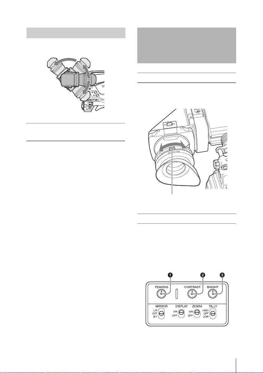
角度を調整する
本機の角度を調整します。
画像/文字表示を上下反転させる
には
本機は、被写体側から見ることもできるよ
うに
180°回転します。
この場合、画面上の画像や文字表示の上下
が逆になります。
MIRRORスイッチをB/Tにすると、画像や文
字表示の上下を反転させて、通常の状態に
戻すことができます。
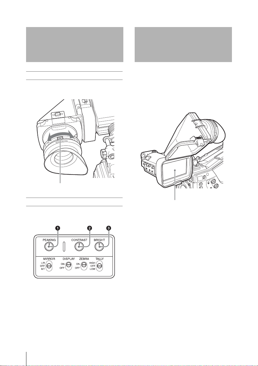
視度と画面を調整する
視度を調整するには
視度調整リングを回して、画像がはっきり
見えるように調整します。
視度調整リング
画面を調整するには
画面の状態を、次の項目について調整でき
ます。
輪郭:
PEAKINGつまみで調整する。
濃淡:
CONTRASTつまみで調整する。
明るさ:
BRIGHTつまみで調整する。
1PEAKINGつまみ
2CONTRASTつまみ
3
BRIGHTつまみ
視度と画面を調整する
9
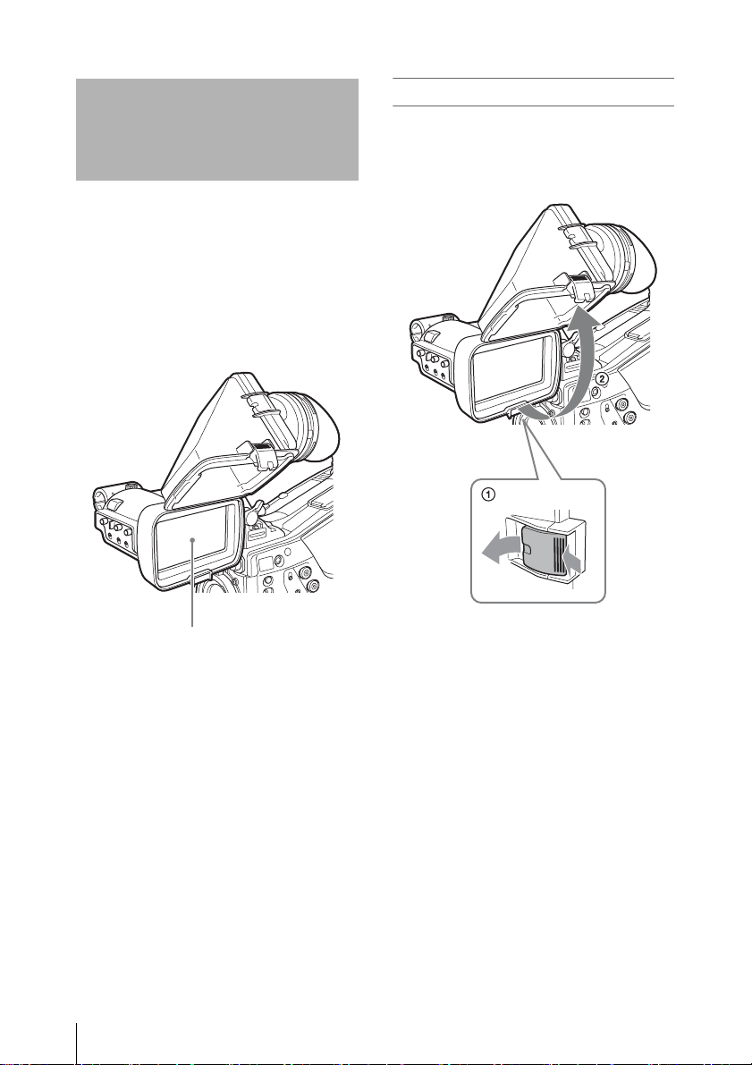
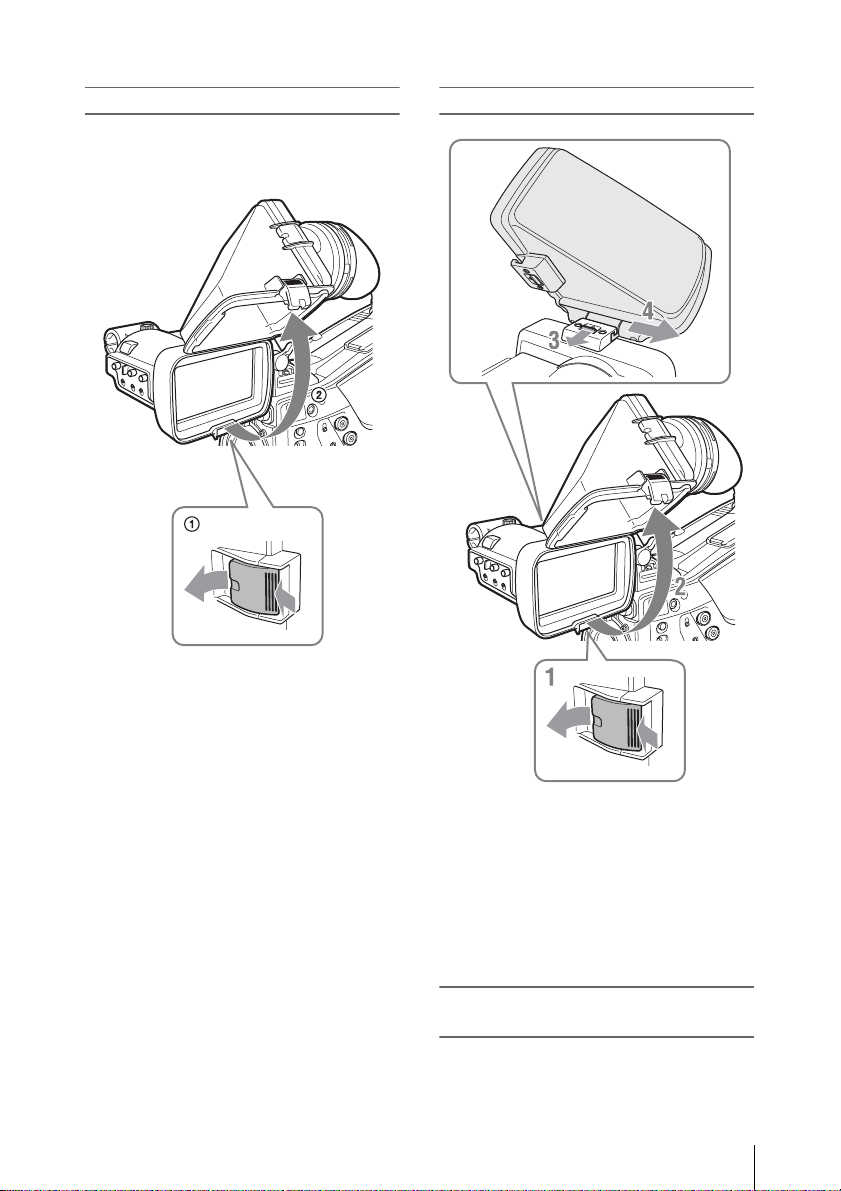
VF筒部/アイピース
部を跳ね上げる
VF筒部/アイピース部を跳ね上げると、内
部の
LCD画面またはその鏡像を見ることが
できます。
ここでは、
について説明します。アイピース部も同様
に跳ね上げたり、取りはずしたりすること
ができます。
VF筒部の跳ね上げ/取りはずし
跳ね上げるには
底のクリップを押してはずし、上に開きま
す。
120°開いた位置でロックします。
LCD画面
VF筒部/アイピース部を跳ね上げる
10
通常はロック位置で使用してください。
ロック位置からさらに開くこともできます
が、再度
は、いったん元の閉じた位置まで戻してか
ら開き直してください。
120°の位置でロックしたい場合
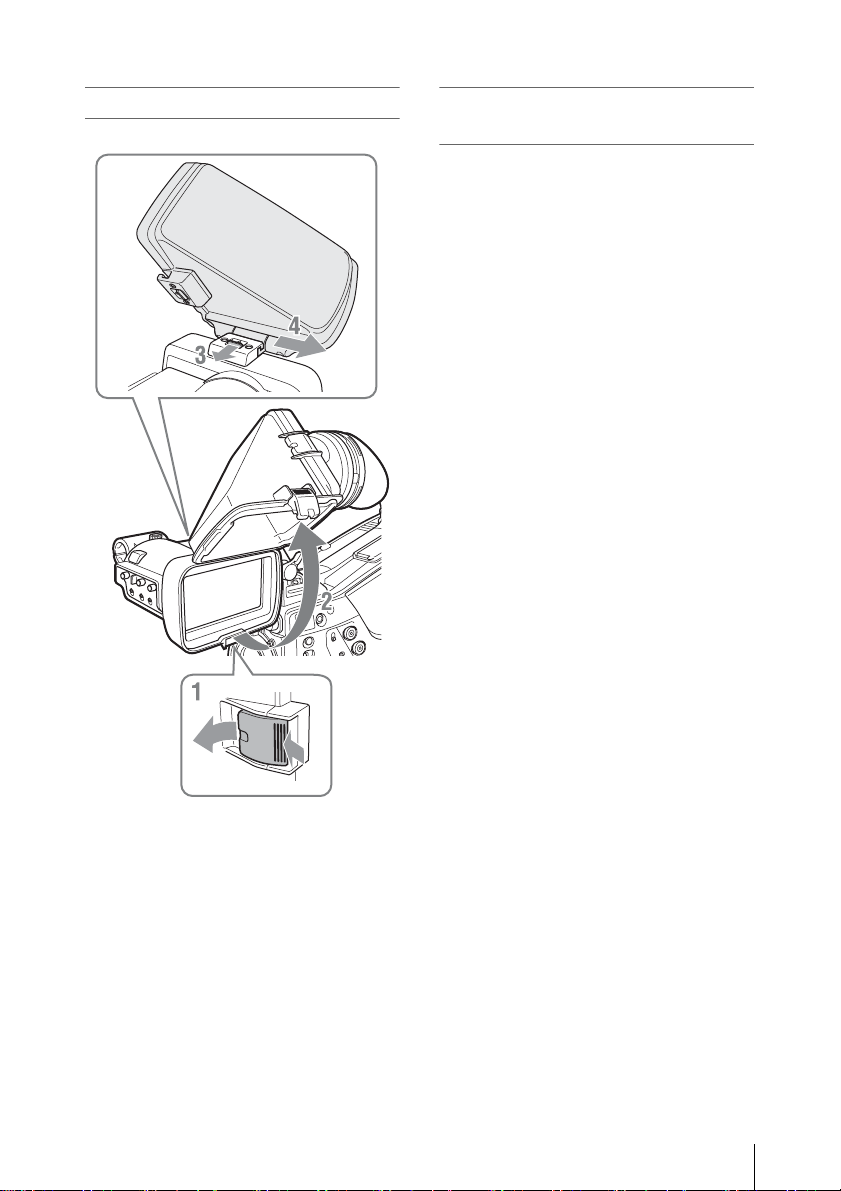
取りはずすには
画像/文字表示を左右反転させる
には
MIRRORスイッチをL/Rにすると、画面上の
画像や文字表示の左右を反転させることが
できます。
1 底のクリップを押してはずす。
2 VF筒部を上げる。
3 上のボタンをVF筒部と反対の方向に
スライドさせてロックをはずす。
4 VF筒部を水平にスライドさせて取り
はずす。
VF 筒部/アイピース部を跳ね上げる
11
画面や内部(
LCD
画面)
をクリーニングする
仕様
本機の画面や内部(LCD画面)をクリーニ
ングするときは、本機をカメラから取りは
ずし、内部の部品を傷つけないように充分
注意して行ってください。
◆ 本機をカメラから取りはずす方法について
は、「カメラに取り付ける」(
覧ください。
VF筒部を取りはずす方法については、「取り
◆
はずすには」(
11ページ)をご覧ください。
8ページ)をご
画面の表面からほこりを取り除くときは
ブロアーをお使いください。
ご注意
シンナーなどの溶剤は、いっさい使わないでくだ
さい。
特殊環境で使用後のアフターケア
海辺やほこりの多い場所、温泉地などで使
用した後は、以下のようなクリーニングや
確認を行ってください。
• セットの中に入っている砂やほこりをエアーブ
ラシ等で慎重に取り除く。
• コネクターの接続面をクリーニングする。
• 上記のクリーニングを行った後に、一般動作
チェックを行い、正常に動作することを確認す
る。
一般
電源
DC10.5〜17.0 V(カメラから供給)
消費電力
2 W
使用温度
0 ℃〜+40 ℃
保存温度
−20 ℃〜+60 ℃
質量
680 g
約
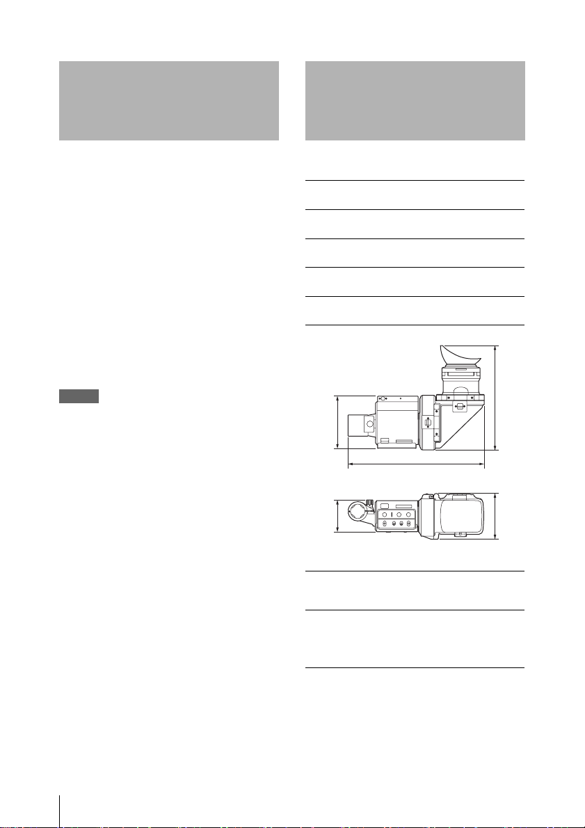
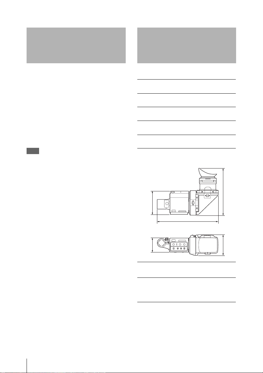
外形寸法
103
255
60 89
(単位: mm)
LCD
3.5型、カラー、TFT半透過型LCD
画像表示部
76.8×43.2 mm(水平/垂直、アスペクト比
16:9)
201
画面や内部(LCD画面)をクリーニングする / 仕様
12

性能
輝度
200 cd/m
アイピース装着時
解像度
500本以上
色温度
6500K(typical)
2
(typical)
接続端子
角型
26ピンコネクター
付属品
オペレーションマニュアル(
1)
別売品
ビューファインダー回転収納機構
BKW-401
関連製品
ソリッドステートメモリーカムコーダー
PMW-500
1) PMW-500に取り付ける場合は、カムコーダー
側のバージョンが
必要です。
1)
Ver. 1.10以上であることが
重要
機器の名称と電気定格は、底面に表示され
ています。
本機の仕様および外観は、改良のため予告
なく変更することがありますが、ご了承く
ださい。
お使いになる前に、必ず動作確認を行ってくだ
さい。故障その他に伴う営業上の機会損失等は
保証期間中および保証期間経過後にかかわらず、
補償はいたしかねますのでご了承ください。
仕様
13

English
Before operating the unit, please read this
manual thoroughly and retain it for future
reference.
IMPORTANT
The nameplate is located on the bottom.
For the customers in the U.S.A.
This equipment has been tested and found
to comply with the limits for a Class B digital
device, pursuant to Part 15 of the FCC
Rules. These limits are designed to provide
reasonable protection against harmful
interference in a residential installation. This
equipment generates, uses, and can radiate
radio frequency energy and, if not installed
and used in accordance with the
instructions, may cause harmful interference
to radio communications. However, there is
no guarantee that interference will not occur
in a particular installation. If this equipment
does cause harmful interference to radio or
television reception, which can be
determined by turning the equipment off and
on, the user is encouraged to try to correct
the interference by one or more of the
following measures:
- Reorient or relocate the receiving
antenna.
- Increase the separation between the
equipment and receiver.
- Connect the equipment into an outlet on a
circuit different from that to which the
receiver is connected.
- Consult the dealer or an experienced
radio/TV technician for help.
For the customers in Europe
This product with the CE marking complies
with the EMC Directive issued by the
Commission of the European Community.
Compliance with this directive implies
conformity to the following European
standards:
• EN55103-1 : Electromagnetic
Interference(Emission)
• EN55103-2 : Electromagnetic
Susceptibility(Immunity)
This product is intended for use in the
following Electromagnetic Environments: E1
(residential), E2 (commercial and light
industrial), E3 (urban outdoors), E4
(controlled EMC environment, ex. TV
studio).
For the customers in Europe
The manufacturer of this product is Sony
Corporation, 1-7-1 Konan, Minato-ku,
Tokyo, Japan.
The Authorized Representative for EMC and
product safety is Sony Deutschland GmbH,
Hedelfinger Strasse 61, 70327 Stuttgart,
Germany.
You are cautioned that any changes or
modifications not expressly approved in this
manual could void your authority to operate
this equipment.
This device complies with Part 15 of the FCC
Rules. Operation is subject to the following
two conditions: (1) this device may not cause
harmful interference, and (2) this device
must accept any interference received,
including interference that may cause
undesired operation.
For the customers in Canada
This Class B digital apparatus complies with
Canadian ICES-003.
14

Table of Contents
Table of Contents
Overview..................................................................................................... 16
Usage Notes................................................................................................. 16
Names and Functions of Parts.................................................................. 17
Attaching the Viewfinder to a Camera.................................................... 18
Adjusting the Position..................................................................... 19
Adjusting the Angle........................................................................ 19
Adjusting the Focus and Image Display .................................................. 20
Raising the Viewfinder Barrel and Eyepiece .......................................... 20
Cleaning the LCD Screen and Interior.................................................... 22
Specifications.............................................................................................. 22
GB
Table of Contents
15

Overview Usage Notes
The CBK-VF01 HD Electronic Viewfinder is a
3.5-inch LCD color viewfinder.
This viewfinder has the following features:
High resolution and wide visual angle
The viewfinder features a high-resolution LCD,
for a horizontal resolution of 500 TV lines or
more.
The large LCD screen allows you to shoot with
ease when the eyepiece is unattached.
Stable picture
The LCD screen provides a stable image without
distortion, regardless of screen brightness.
High-performance loupe
The 2-group 3-element lens (including aspheric
lens) delivers pictures with low distortion and
allows adjustment over a wide range of visibility.
Adjustable, detachable eyepiece
Raising or detaching the eyepiece allows you to
shoot while viewing the viewfinder screen from a
distance.
Adjustable, detachable viewfinder barrel and
specially designed transflective LCD screen
Raising or detaching the viewfinder barrel allows
you to work while viewing the LCD screen
directly.
The transflective LCD screen allows visibility in
any environment.
Place of use
When using the viewfinder in low temperature
environments, dynamic resolution levels may
decrease during the period immediately after you
turn on the power.
Permanently lit or flashing pixels on the
LCD panel
The LCD panel fitted to this unit is manufactured
with high precision technology, giving a
functioning pixel ratio of at least 99.99%. Thus a
very small proportion of pixels may be “stuck”,
either always off (black), always on (red, green,
or blue), or flashing. In addition, over a long
period of use, because of the physical
characteristics of the liquid crystal display, such
“stuck” pixels may appear spontaneously. These
problems are not a malfunction. Note that any
such problems have no effect on recorded data.
LCD image display
Due the physical characteristics of LCD panels,
there may be a decrease in brightness or change in
color temperature over a long period of use.
These problems are not a malfunction.
In addition, these occurrences will not affect
recorded data.
Overview / Usage Notes
16
Viewfinder lens
Do not leave the viewfinder lens facing toward a
strong light source, such as sunlight.
Burnout of the LCD panel or fire may occur if the
lens focuses the sunlight or other strong light
source.
Maintenance
• Use a dust blower to remove dust from the
screen.
• Do not use solvents such as thinner to clean the
screen.
Names and Functions of
Parts
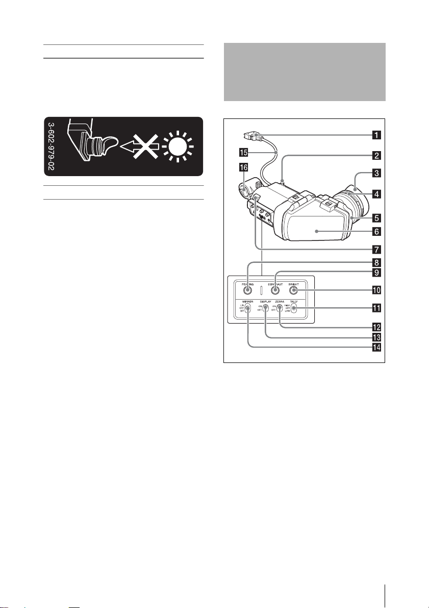
a Plug
Connect to the VF connector (rectangular) on the
camera.
b Stopper
Prevents the viewfinder from coming off the
camera when it is slid from side to side.
c Eyecup
d Diopter adjustment ring
Allows for optimal focus adjustment.
e Eyepiece
Raise this up or detach this when required by the
situation.
f Viewfinder barrel
Raise this up or detach this when required by the
situation.
Names and Functions of Parts
17
g Tally indicator
Lights up when recording is started by a press of
the REC START button on the camera, the VTR
button on the lens, or the VTR button on the
remote control unit.
When an abnormality occurs, the tally indicator
flashes to indicate a warning.
h PEAKING control
Turn this control clockwise to adjust the picture
sharpness and make focusing easier. This control
has no effect on the output signals of the camera.
i CONTRAST control
Adjusts the contrast of the screen. This control
has no effect on the output signals of the camera.
j BRIGHT control
Adjusts the brightness of the screen. This control
has no effect on the output signals of the camera.
k TALLY switch
Controls the tally indicator.
HIGH: The tally indicator brightness is set to
high.
OFF: The tally indicator is disabled.
LOW: The tally indicator brightness is set to low.
l ZEBRA (zebra pattern) switch
Controls the zebra pattern display as follows.
ON: Display a zebra pattern.
OFF: Do not display a zebra pattern.
m DISPLAY switch
Turns the display of text information on and off.
ON: Display text information.
OFF: Do not display text information.
Attaching the Viewfinder
to a Camera
CAUTION
When the viewfinder is attached, do not leave the
viewfinder lens facing toward the sun. Direct sunlight
can enter through the lens, be focused in the viewfinder
and cause fire.
Notes
When attaching the viewfinder, make notes of the
following points.
• Be sure to power off the camera before coupling the
viewfinder connector to the camera’s VF connector
(rectangular). If you make this connection when the
camera power is on, the viewfinder may not function
properly.
• Couple the viewfinder connector firmly to the
camera’s VF connector (rectangular). If the coupling is
loose, noise may appear on the video or the tally
indicator may not operate properly.
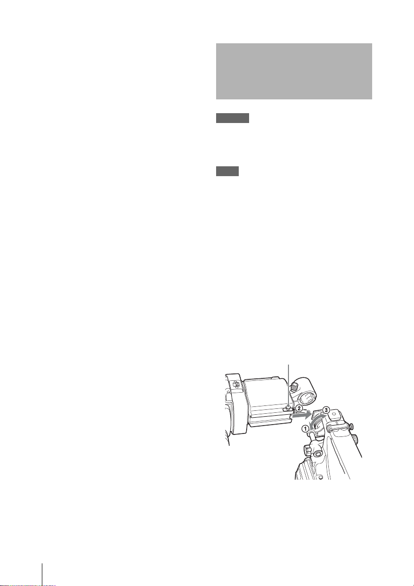
1 1 Loosen the viewfinder left-to-right
positioning ring on the camera, 2
attach the viewfinder to the viewfinder
fitting shoe on the camera, and 3
tighten the viewfinder left-to-right
positioning ring.
Stopper
Viewfinder leftto-right
positioning ring
n MIRROR switch
The image display on the screen becomes
reversed horizontally or vertically when the
viewfinder barrel is raised up or rotated. Use this
switch to control the image display in such
situations.
L/R: Reverse the image horizontally.
OFF: Do not reverse the image.
B/T: Reverse the image vertically.
o Viewfinder cable
p Microphone holder
Attaching the Viewfinder to a Camera
18
2 Couple the viewfinder connector to the
VF connector (rectangular) on the
camera.
VF connector (rectangular)
Detaching the viewfinder
You can detach the viewfinder by following the
attaching procedure in reverse order, but there is
an additional action to take: when detaching the
viewfinder from the fitting shoe, pull up the
stopper. (See the illustration in step 1.)
Adjusting the Position
Adjusting the Angle
You can adjust the angle of the viewfinder.
Reversing the display (image/text
indication) vertically
The viewfinder can be rotated as much as 180
degrees toward the direction facing the subject.
When you do this, the picture and other
information displayed in the screen appear upside
down. To restore the normal display, set the
MIRROR switch to B/T.
To adjust the viewfinder left-to-right position,
loosen the left-to-right positioning ring on the
camera, and to adjust the front-to-back position,
loosen the front-to-back positioning knob on the
camera.
Viewfinder left-to-right positioning ring
Viewfinder front-to-back positioning knob
Attaching the Viewfinder to a Camera
19
Adjusting the Focus and
Raising the Viewfinder
Image Display
Adjusting the focus
Turn the diopter adjustment ring until the image
is sharpest.
Diopter adjustment ring
Adjusting the image display
Adjust the brightness, con trast, and peaking of the
display with the controls shown below.
Barrel and Eyepiece
You can view the LCD screen inside the
viewfinder or its mirrored image by raising up the
viewfinder barrel or the eyepiece.
This section describes how to raise the viewfinder
barrel and detach it. The eyepiece can also be
raised and detached in the same way.
LCD screen
1 PEAKING control
2 CONTRAST control
3 BRIGHT control
Adjusting the Focus and Image Display / Raising the Viewfinder Barrel and Eyepiece
20
Raising the viewfinder barrel
Push the clip on the bottom to release and flip up
the viewfinder barrel.
It locks at the 120-degree position.
Normally use it in the locked position.
Although you can open it farther from the lock
position, once return it to the closed position to
lock it at the 120-degree position again.
Detaching the viewfinder barrel
1 Push the clip on the bottom to release.
2 Flip up the viewfinder barrel.
3 Slide the knob on the top to the opposite
side of the viewfinder barrel.
4 Detach the viewfinder barrel by
horizontally sliding it.
Reversing the display (image/text
indication) horizontally
By setting the MIRROR switch to L/R, you can
reverse the picture and other information
displayed in the screen horizontally.
Raising the Viewfinder Barrel and Eyepiece
21
Cleaning the LCD Screen
and Interior
Specifications
When cleaning the LCD screen or interior of the
viewfinder, detach the viewfinder from the
camera, detach the viewfinder barrel from the
body, and take care not to damage the
components.
For details on how to detach the viewfinder, see
“Attaching the Viewfinder to a Camera” (page 18).
For details on how to detach the viewfinder barrel,
see “Detaching the viewfinder barrel” (page 21).
To remove dust from the screen
Use a dust blower.
Note
Do not use solvents such as thinner.
After using the viewfinder in harsh environments
Check the following points after using the
viewfinder in a harsh environment such as a
beach, a dusty area, or a hot spring resort.
• Use an airbrush to carefully remove any dust or
sand from inside the viewfinder.
• Clean the contacts of the connector.
• Check that the viewfinder is working correctly.
General
Power supply
10.5 to 17.0 V DC (supplied by the camera)
Power consumption
2 W
Operating temperature
0 ºC to 40 ºC (32 ºF to 104 ºF)
Storage temperature
–20 ºC to +60 ºC (–4 ºF to +140 ºF)
Mass
Approx. 680 g (1 lb 8.0 oz)
External dimensions
Unit: mm (inches)
103
1
/8)
(4
1
255 (10
/8)
60
3
/8)
(2
201
(8)
89
(35/8)
Cleaning the LCD Screen and Interior / Specifications
22
LCD
3.5-inch color TFT transflective LCD
Image display area dimensions
76.8 × 43.2 mm (3
(H/V, 16:9 aspect ratio)
1
/8 × 13/4 inches)
Performance
Brightness
Resolution
Color temperature
2
200 cd/m
(typical) (when eyepiece is attached)
500 lines or more
6500 K (typical)
Connector
Rectangular 26-pin connector
Supplied accessories
Operation manual (1)
Optional accessories
Viewfinder Rotation Assembly
BKW-401
Related accessories
Solid-State Memory Camcorder
1) To attach the viewfinder to the PMW-500, the
firmware version on the camcorder must be 1.10 or
later.
PMW-500
1)
Design and specifications are subject to change
without notice.
Note
Always verify that the unit is operating
properly before use. SONY WILL NOT BE
LIABLE FOR DAMAGES OF ANY KIND
INCLUDING, BUT NOT LIMITED TO,
COMPENSATION OR REIMBURSEMENT
ON ACCOUNT OF THE LOSS OF PRESENT
OR PROSPECTIVE PROFITS DUE TO
FAILURE OF THIS UNIT, EITHER DURING
THE WARRANTY PERIOD OR AFTER
EXPIRATION OF THE WARRANTY, OR
FOR ANY OTHER REASON
WHATSOEVER.
Specifications
23
 Loading...