

Page 1

ENG Style Buildup Kit
Operating Instructions
5-010-028-11 (1)
GB
CBK-FS7BK
Extension Unit Software Version 2.0
Network Module Software Version 3.36
© 2019 Sony Corporation
Page 2

0002
Table of Contents
1. Overview
Features .............................................................................. 3
Location and Function of Parts .......................................... 4
2. Device Setup
Attaching the Shoulder Plate ............................................ 7
Attaching the Handle Adapter and Top Plate ................... 8
Attaching the Viewfinder .................................................. 9
Attaching the Extension Unit ........................................... 10
Attaching a Portable Wireless Tuner (when using a
wireless microphone) .............................................. 12
3. Device Adjustment and Setup
Adjusting the Viewfinder ................................................. 13
Adjusting the Shoulder Pad ............................................. 16
4. Network Function Setup
Compatible Terminal Devices and Functions .................. 17
Turning On the Network Module .................................... 18
Setting the Camcorder ..................................................... 19
Connecting to a Terminal Device via Wireless LAN ........ 20
Connecting to the Internet ..............................................22
6. Network Function Setup Using the Web Menu
Web Menu .......................................................................30
Streaming Format Settings ..............................................32
Proxy Format Settings ......................................................34
System Settings ...............................................................35
Access Point Settings (AP Settings) ................................ 37
Wireless LAN settings (Station Settings) ........................ 38
Modem Settings ...............................................................39
Wired LAN Settings .......................................................... 40
Upload Settings ................................................................ 41
Checking File Uploading (Job List) .................................. 43
7. Maintenance
Updating the Unit ............................................................ 44
8. Appendix
Usage Precautions ............................................................45
Troubleshooting ............................................................... 46
Error/Warning Indications ............................................... 47
Licenses ............................................................................ 48
Specifications ................................................................... 51
5. Network Function Operations
Recording the Video of a Camcorder ............................... 24
Uploading a File ............................................................... 27
Streaming Live Video from the Camcorder ..................... 28
Controlling the Camcorder Remotely .............................. 29
Page 3

1. Overview
0003
Features
The CBK‑FS7BK is an accessory kit that attaches
to a PXW‑FS7‑series camcorder to provide the
stability and operability of the camcorder when
used shoulder camcorder style. In addition to
the XDCA‑FS7 functionality, it features a robust
viewfinder, sliding shoulder plate, wireless
audio receiver slot, and comprehensive network
functions. FS7‑series camcorders can also be
operated with a B4 lens by attaching the LA‑EB1
(option).
Remote Operation of Camcorder via a
Wireless LAN
When the unit is connected to a PXW‑FS7‑series
camcorder (hereinafter, “camcorder”) by USB cable,
you can operate the camcorder remotely from a
smartphone/tablet/computer that is connected
via wireless LAN.
Creating and Recording a Proxy File
The unit creates a proxy file (low resolution) and
records it on an SD card that is inserted into the
unit, from the HD‑SDI input video and audio
signals that are shot or played on the camcorder.
The created file is called “XAVC (R) Proxy.”
Recording starts/stops automatically in lock with
the camcorder Rec/Stop control signals that are
embedded in the HD‑SDI signal.
When recording using the camcorder, you
can create a proxy file of the same duration
that inherits the information of the original file
recorded on the camcorder.
Uploading a File via a 3G/4G/LTE
Network, Wireless LAN, or Wired LAN
You can upload a proxy file (low resolution) that
is recorded on an SD card in the unit to a server
on the Internet via a 3G/4G/LTE network, wireless
LAN, or wired LAN.
Monitoring Camcorder video via a
Wireless LAN
The unit can create a stream (H.264) from the
camcorder video, which can be monitored using
the “Content Browser Mobile” application on a
smartphone/tablet via wireless LAN.
“Content Browser Mobile”
Application*
You can configure the settings of the unit from a
smartphone/tablet using the “Content Browser
Mobile” application.
* For details about the “Content Browser Mobile”
application, contact your Sony dealer or a Sony service
representative.
Streaming Camcorder Video/Audio
via a 3G/4G/LTE Network, Wireless
LAN, or Wired LAN
The unit can create a stream (H.264/AAC‑LC
compression) from the camcorder video/audio,
which can be streamed via a 3G/4G/LTE network,
wireless LAN, or wired LAN.
[Note]
If you start streaming, proxy recording and file transfer
cannot be performed.
High Quality Streaming using Sony’s
QoS Technology
When connected to a Connection Control
Manager (CCM) of a Sony Network RX Station
(option) or XDCAM air*, the unit supports high
quality streaming and file uploading via the CCM.
* XDCAM air is a cloud service that is provided by Sony. To
use this service, registration is required.
XDCAM air is not provided in some regions. For details on
areas where the service is provided, refer to the following
site.
https://www.xdcam‑air.com
For more details, contact a Sony professional sales
representative.
In addition, refer to the following sites for the privacy
policy of XDCAM air.
Terms of service
https://www.xdcam‑air.com/site/tos_eu.html
Privacy policy of XDCAM air
https://sony‑imaging‑products‑solutions.co.jp/pp/sips/
en/index.html
Privacy policy of professional ID
https://www.pro‑id.sony.net/#/privacyPolicy
[Notes]
The unit works in combination with the latest version of
the Network RX Station.
If network client mode for streaming with Sony’s QoS
Technology is set to on with proxy recording enabled,
the streaming bit rate is limited by the proxy recording
setting. File uploading stops when streaming is started.
You can change the proxy recording setting by operating
the CCM.
You can perform stable streaming with high picture
quality using multiple networks. (Depending on the
scene, the target bit rate may be exceeded.)
This function is available when [Proxy Recording] is set to
“Off” or when [Proxy Recording] cannot be set.
Use separate network connections to acquire stable
performance.
To use this function, contact your Sony professional sales
representative.
Page 4
1. Overview
0004
Location and Function of Parts
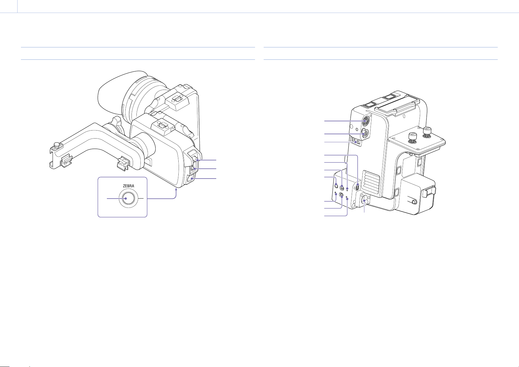
Viewfinder
4
1. CONTRAST adjustment knob (page 13)
2. MIRROR switch (page 14)
3. PEAKING button
The peaking indicator can be switched on/off.
4. ZEBRA button
The zebra pattern indicator can be switched on/
off.
Extension Unit
Front / left sides
1
2
3
1
2
3
1. DATA IN/OUT connector
Connect to the supplied handle adapter.
Connect in order to use a portable wireless tuner.
2. DC OUT connector (4-pin round type)
Outputs 12V DC power.
Connect when using an LA-EB1 Lens Adapter
(option).
3. LIGHT connector (2-pin)
Outputs 12 V DC power.
4. CAM connector (USB Micro B type)
Connect to the camcorder using the supplied USB
cable. Connect in order to control the camcorder
remotely.
4
5
6
7
8
9
10 11
5. ST indicator
Lights blue when the wireless LAN mode of the
unit is STA mode. It is off when in AP mode. It
flashes blue when executing the WPS function.
6. WIRELESS (wireless LAN mode select) switch
Sets the wireless LAN mode of the unit.
“AP”: AP mode (access point mode) (page 20)
“ST”: STA mode (station mode) (page 22)
7. WPS button
Used for the WPS function.
Using Wi-Fi Protected Setup™ (WPS), you can
configure connected devices and access points
semi-automatically.
8. RESET button
Resets the network functions of the unit to the
factory default settings.
Page 5
1. Overview: Location and Function of Parts
0005
9. Network module power switch
Set to ON to link the power to the power supply
of the camcorder. Set to STANDBY to turn off the
network functions.
[Note]
If the camcorder is turned off or the SD card is removed
while the SD card is being accessed, the integrity of data
on the card cannot be guaranteed. All data recorded on
the card may be discarded. Always make sure the access
indicator is off before turning off the camcorder or removing
the SD card.
[Tip]
When the network module power switch is set to the
STANDBY position, the power consumption is reduced,
extending the battery life of the camcorder.
10. STATUS indicator
Displays the status of the network functions.
STATUS indicator Status of network
functions
Off
Lit light green Power on (normal
Flashes light green
slowly
(0.5 second intervals)
Flashes light green
rapidly
(0.2 second intervals)
Flashes red slowly
(0.5 second intervals)
Flashes red rapidly
(0.2 second intervals)
Power off
During normal
operation
operation)
Connecting in STA mode
Transferring files
No input signal from
SDI IN connector
Intermittent input
signal from SDI IN
connector
Default setting error
when power applied
Wireless LAN module/
modem not available
STATUS indicator Status of network
functions
Lit orange
Flashes orange slowly
(0.5 second intervals)
Modem
communication not
available
No connection to
access point (STA
mode)
File transfer failed
11. SDI IN connector (BNC type)
Connect to the camcorder using the supplied BNC
cable to input the SDI signal that is output from
the camcorder. Use to record the video from the
camcorder on the unit.
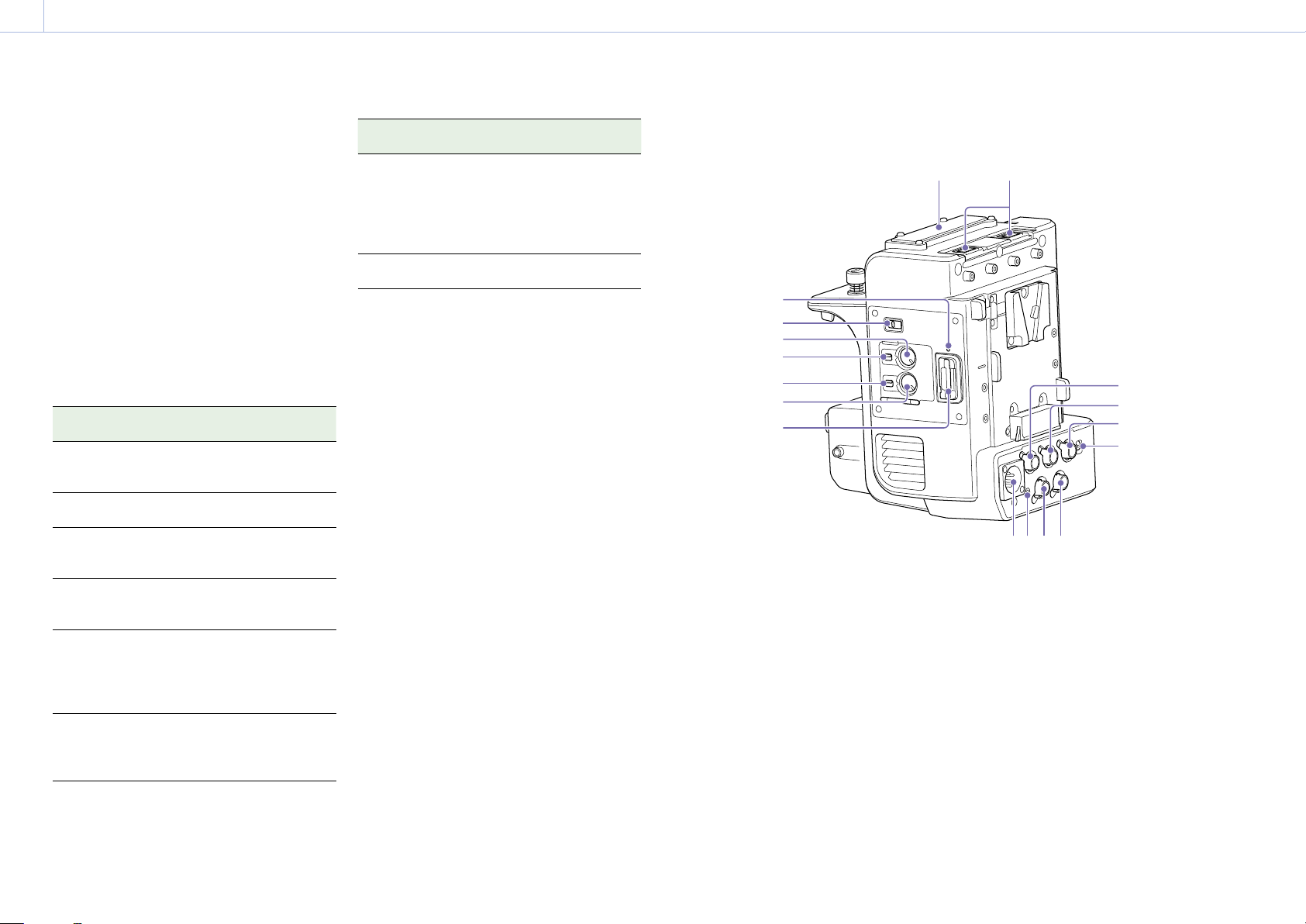
Top / right / rear sides
3
4
5
6
7
8
9
1. USB connector (type A)
Attach to wireless LAN module supplied with the
camcorder, or modem (option).
2. Portable wireless tuner connector
Attach to portable wireless tuner when using a
wireless microphone.
3. SD card access indicator
4. Audio signal select switch
Selects the signal line connection of the multiinterface shoe of the camcorder.
MI shoe: Enable the multi-interface shoe.
WIRELESS AUDIO: Enable input from a portable
wireless tuner instead of the multi-interface
shoe.
2
1
14
15
16
17
5. CH1 INPUT LEVEL dial
Adjusts the WIRELESS AUDIO CH1 audio recording
level manually.
6. CH1 LEVEL CONTROL switch
Sets the adjustment method of the WIRELESS
AUDIO CH1 audio recording level.
AUTO: Adjust automatically.
MAN: Adjust manually.
7. CH2 LEVEL CONTROL switch
Sets the adjustment method of the WIRELESS
AUDIO CH2 audio recording level.
AUTO: Adjust automatically.
MAN: Adjust manually.
8. CH2 INPUT LEVEL dial
Adjusts the WIRELESS AUDIO CH2 audio recording
level manually.
Page 6
1. Overview: Location and Function of Parts
0006
9. SD card slot
Insert an SD card (not supplied) for XAVC proxy
recording.
10. DC IN connector (XLR type, 4-pin)
11. Recording indicator
12. RAW OUT connector (BNC type)
13. SDI OUT connector (BNC type)
SDI IN pass-through output (when network
module is on).
14. GENLOCK IN connector (BNC type)
15. REF OUT connector (BNC type)
16. TC IN/OUT connector (BNC type)
17. TC IN/OUT switch
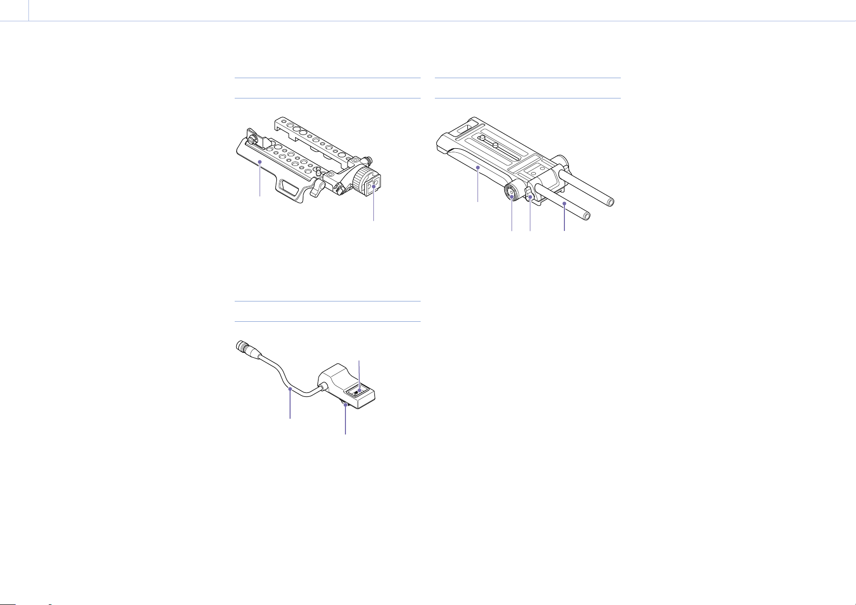
Top plate
1
1. Cable cover
2. Viewfinder attachment shoe
Handle adapter
1
2
Shoulder Plate
1
2
2 3 4
1. Shoulder pad
2. Rosette (left and right sides)
Supports attachment of general-purpose handle
grip.
3. Rod lock lever (left and right sides)
Use to attach and remove ø15 rods.
When attaching, turn the rod lock lever clockwise
3
to secure the rod.
When removing, turn the rod lock lever
counterclockwise to loosen the rod.
If a lever is in a position that makes it difficult to
turn, pull the lever out and rotate it to an angle
that will make operation easier. Push the lever in
again when the lever is in the desired position.
4. ø15 rods
1. DATA IN/OUT cable
2. Handle connector (for camcorder)
3. Handle connector (for handle)
Page 7

2. Device Setup
0007
Attaching the Shoulder Plate
You can attach the shoulder plate to the
camcorder.
1 Remove the two screws and coin-slot screw,
and remove the shoulder pad from the
camcorder.
Shoulder pad
2 Attach the joint plate to the camcorder, and
secure in position using the three screws in
the order shown.
3 Insert the shoulder plate screws through the
3/8-16UNC screw holes of the camcorder and
the 3/8-16UNC screw holes of the joint plate,
and tighten the screws.
[Note]
Always secure with screws in two locations.
Removing the Shoulder Plate
Unscrew the two 3/8-16UNC screws, and remove
the shoulder plate.
Joint plate
Page 8
2. Device Setup
0008
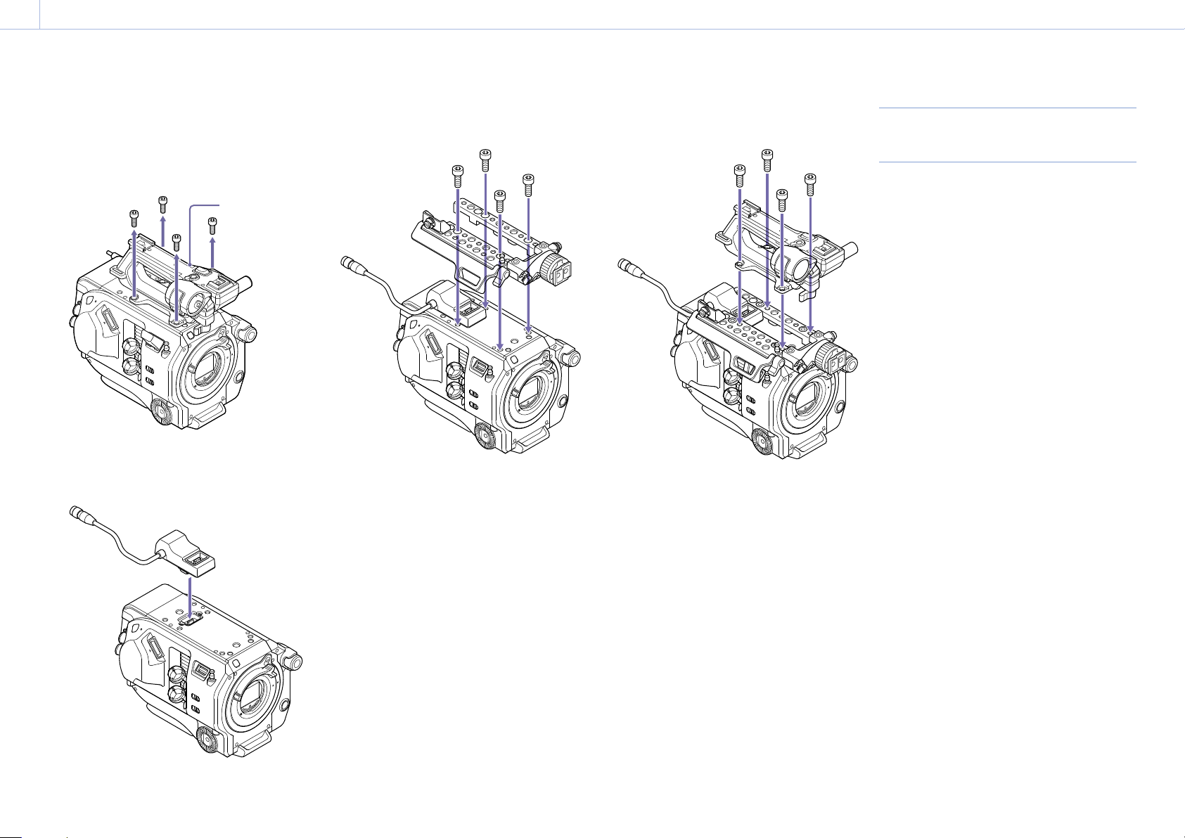
Attaching the Handle Adapter and Top Plate
You can attach a handle adapter and top plate to
the camcorder.
1 Remove the four hex screws, and remove the
handle.
Handle
2 Attach the handle adapter.
Connect the connector of the handle adapter
to the connector of the camera handle.
3 Attach the top plate, and secure it in place
using four supplied hex screws.
4 Attach the handle, and secure it in place using
four hex screws.
5 Connect the DATA IN/OUT cable of the handle
adapter to the DATA IN/OUT connector of the
extension unit (page 10).
Removing the Top Plate and Handle
Adapter
Remove in the reverse procedure of attachment.
Page 9
2. Device Setup
0009
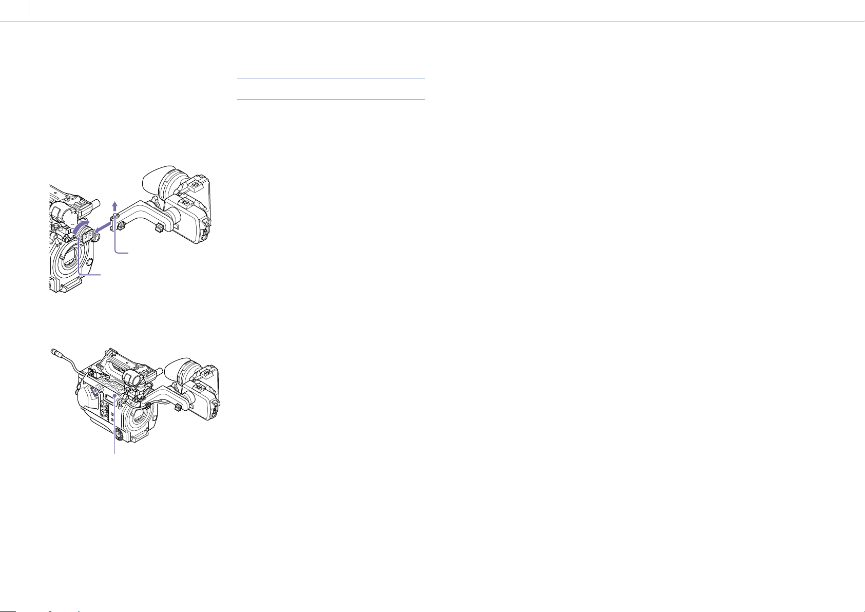
Attaching the Viewfinder
Use the following procedure to attach the
viewfinder to the camcorder.
1 Pull out the slide stopper [1] and
simultaneously slide the viewfinder on to the
viewfinder attachment shoe of the top plate
[2], and turn the ring of the top plate to secure
the viewfinder in position [3].
[1]
[2]
[3]
Slide stopper
Ring
2 Lift up the cable cover of the top plate, and
connect the viewfinder cable to the viewfinder
connector of the camcorder.
Removing the Viewfinder
Remove in the reverse procedure of attachment.
Cable cover
Page 10
2. Device Setup
00010
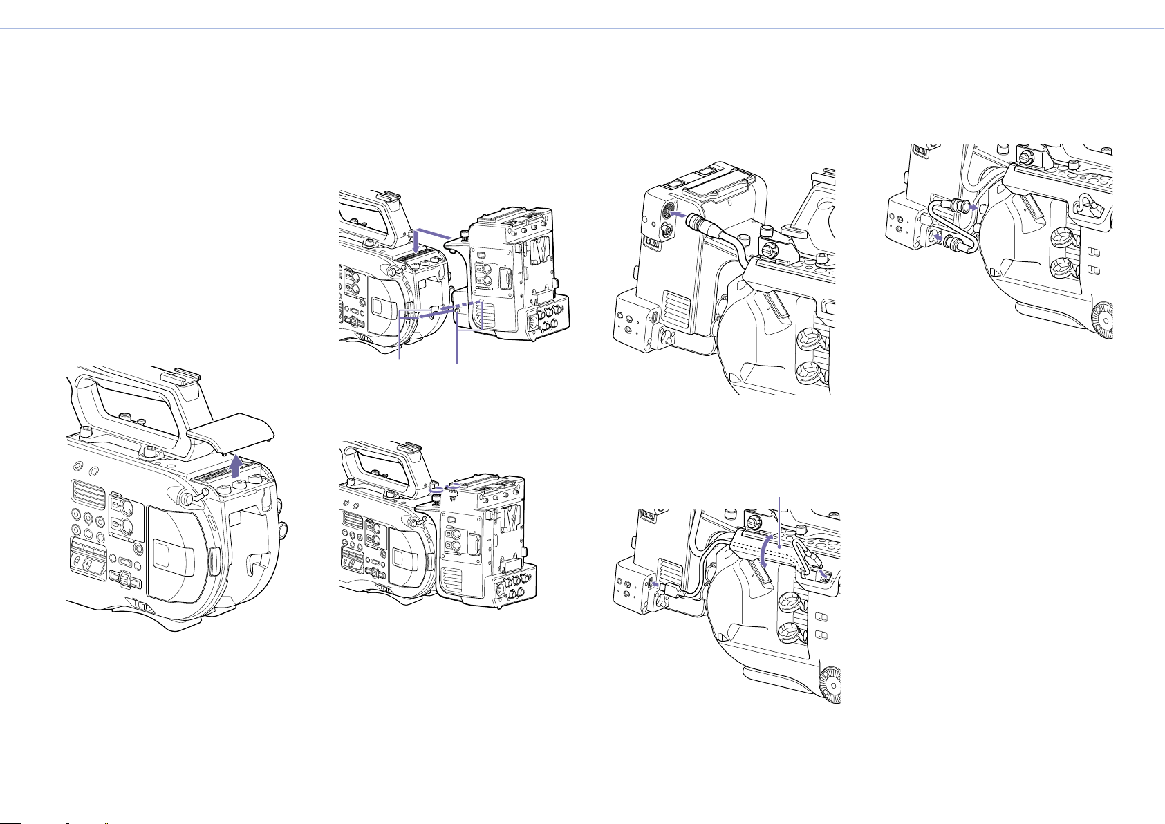
Attaching the Extension Unit
You can add functions to the camcorder, such
as a V-shoe battery or external sync signal, by
attaching an extension unit to the camcorder.
ProRes recording to an XQD card inserted in the
camcorder is also supported.
[Notes]
The camcorder battery pack cannot be used when an
extension unit is attached to the camcorder. You must
attach a battery pack to the extension unit or connect an
external power supply to the DC IN connector.
Attach/remove the extension unit while the camcorder is
turned off.
1 Remove the battery pack attached to the
camcorder.
2 Remove the cover of the extension unit
connector section.
3 Align the protrusions of the extension unit
with the left and right grooves of the
camcorder and slide all the way in, then slide
the extension unit down into the connector
section.
Grooves Protrusions
4 Tighten the two screws on the top of the
extension unit to secure the extension unit.
5 Connect the DATA IN/OUT cable of the handle
adapter (page 8) to the DATA IN/OUT
connector of the extension unit.
6 Connect the extension unit to the camcorder
using the USB cable.
You can stow the USB cable under the cable
cover of the top plate.
Cable cover
7 Connect the extension unit to the camcorder
using the SDI cable.
Page 11
2. Device Setup: Attaching the Extension Unit
00011
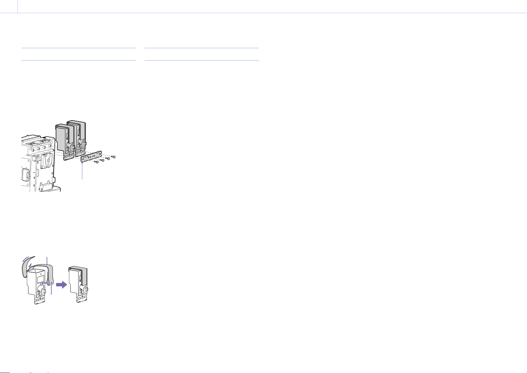
Attaching the Dongle Guards
You can attach a dongle guard to protect a
modem or other USB device attached to a USB
connector.
Attach the dongle guard and dongle guard
mounting bracket to the extension unit, and
secure in position using the mounting bracket
screws.
Dongle guard mounting plate
Attaching using fastener strap
Attach the fastener strap to the dongle guard to
secure a USB device in place.
Attach the loop of the strap to the back of the
dongle guard and pass the strap over the guard as
shown below.
Fastener strap
Removing the Extension Unit
1 Disconnect the DATA IN/OUT cable of the
handle adapter (page 8).
2 Disconnect the USB cable.
3 Disconnect the SDI cable.
4 Unscrew the two screws on the top of the
extension unit to remove the extension unit
from the camcorder.
Loop
Page 12
2. Device Setup
00012
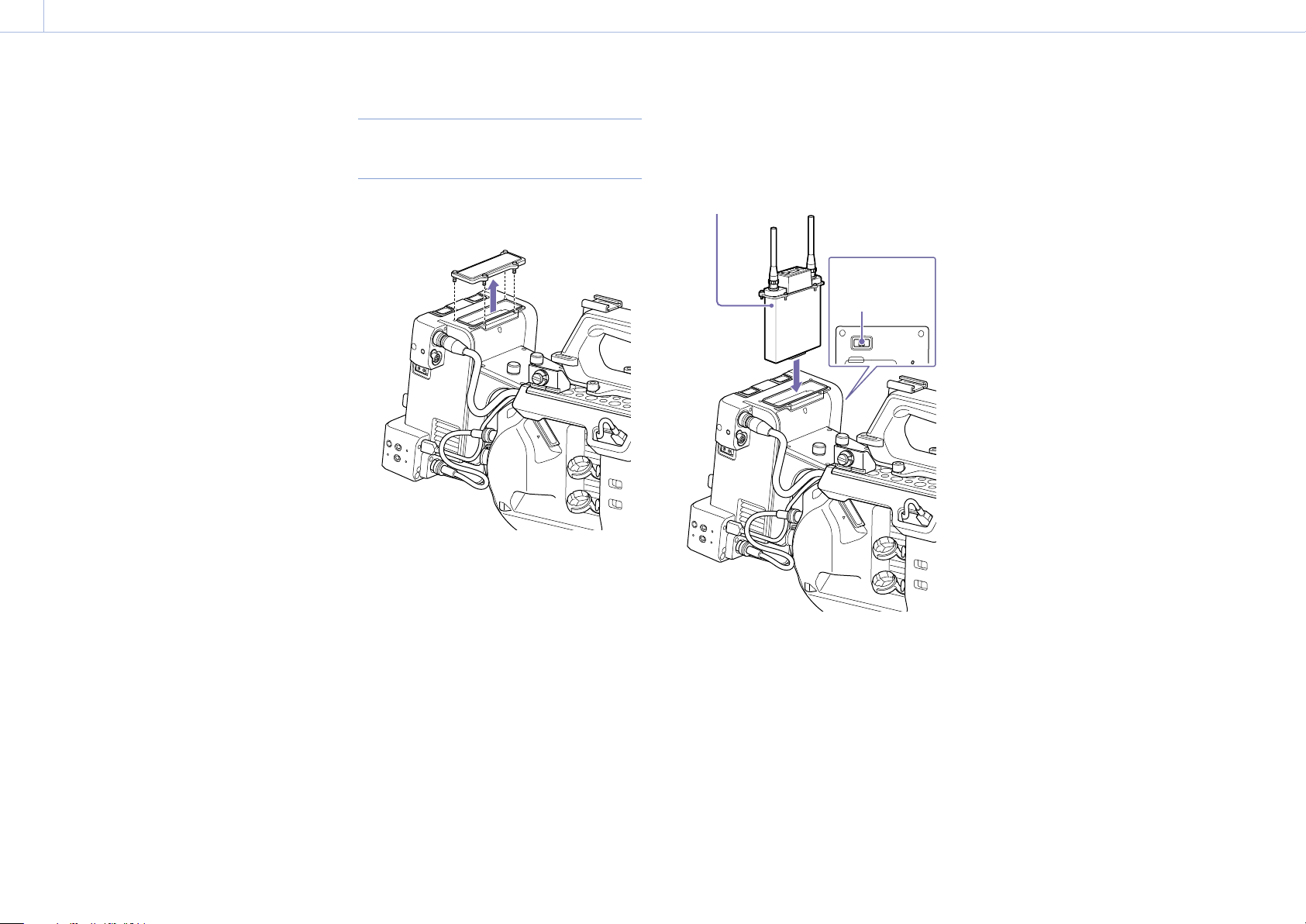
Attaching a Portable Wireless Tuner (when using a wireless microphone)
When using a 1‑channel analog wireless tuner, a loud
You can attach any one of the following portable
wireless tuners, once the camcorder is turned off,
when using a wireless microphone.
DWR‑S02D/DWR‑S02DN Digital Wireless
Receiver
URX‑S03D UHF Synthesizer Diversity Tuner
Also refer to the instruction manual of the portable wireless
tuner.
Attaching a DWR‑S02D/
DWR‑S02DN/URX‑S03D
1 Remove the four screws securing the cover of
the insertion slot, and remove the cover.
2 Insert the DWR‑S02D, DWR‑S02DN, or
URX‑S03D, and secure it in place using four
screws.
DWR‑S02D, DWR‑S02DN, or
URX‑S03D
noise may occur on Shoe 2. In this case, set [Audio Input]
>[CH Input Select] to [Shoe 1] only.
Operating the audio signal select switch while the power
is turned on may cause a loud noise in the audio signal.
Operate the audio signal select switch while the unit is
turned off.
The separate input level adjustment functions on the
camcorder for each channel cannot be used.
[Note]
The wireless tuners that are supported will vary depending
on the region and the corresponding frequency band.
Consult your Sony dealer or Sony sales representative for the
wireless tuners that can be used with this unit.
Audio signal select
switch
3 Set the audio signal select switch of the
extension unit to the WIRELESS AUDIO
position.
4 On the camcorder, set the desired [CH Input
Select] setting for routing the WIRELESS AUDIO
signal to [Shoe 1] or [Shoe 2].
Adjust the input level using the switch and dial
of the extension unit.
[Notes]
The multi‑interface shoe cannot be used at the same time.
“XLR Adaptor” is displayed for both Shoe 1 and Shoe 2 on
the audio status screen of the camcorder.
Page 13
3. Device Adjustment and Setup
00013
Adjusting the Viewfinder
You can adjust the position, angle, contrast and
other display conditions of the viewfinder for best
viewing in various shooting situations.
Contrast and other adjustments have no effect on
pictures being recorded.
Adjusting the Focus in the Viewfinder
The eyepiece focusing (diopter compensation)
ring enables adjustment to match the eyesight
of the operator so that the operator can view the
image clearly in the eyepiece.
Diopter adjustment ring
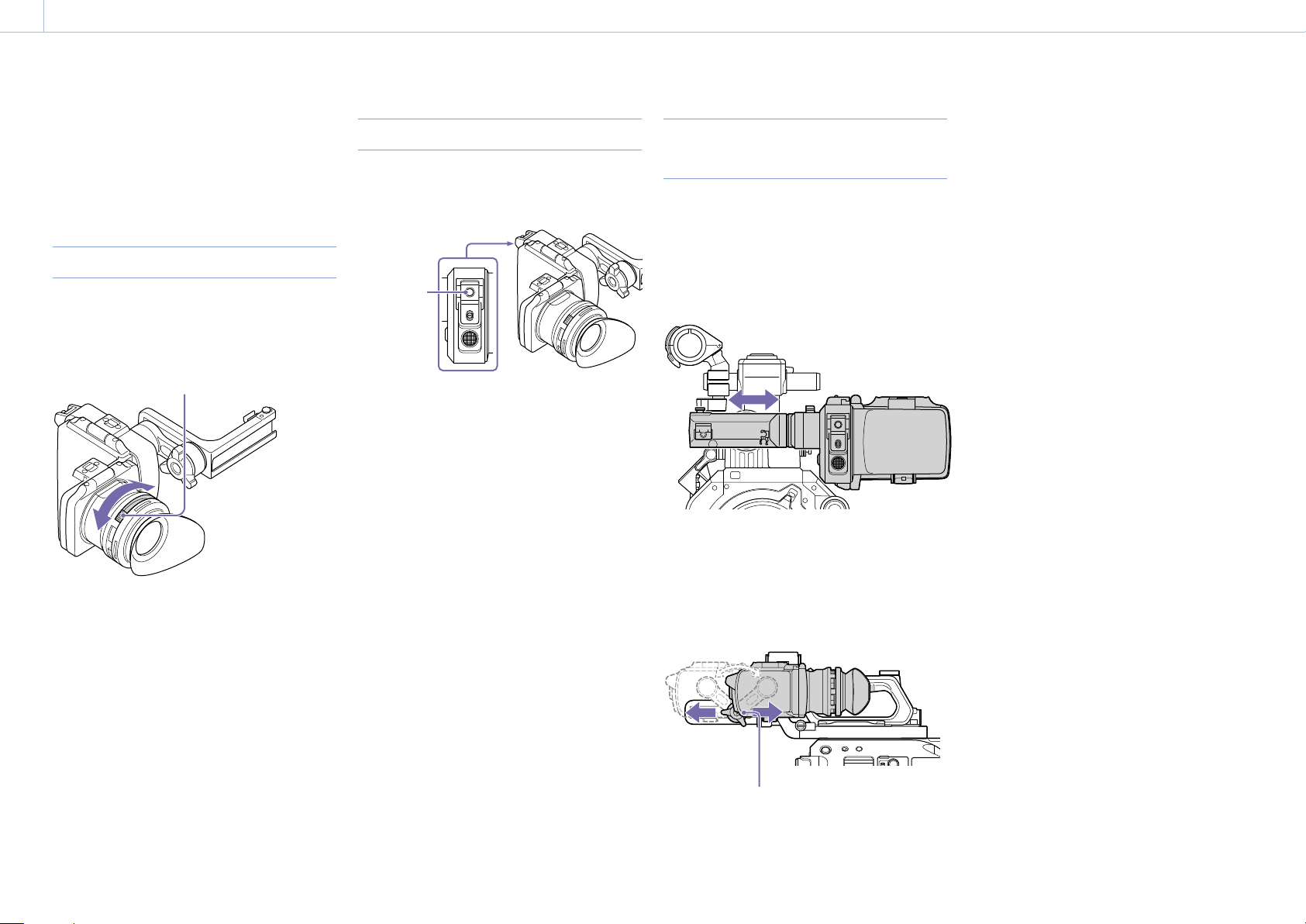
Adjusting the Contrast
Adjust the contrast using the CONTRAST
adjustment knob on the rear side of the
viewfinder.
CONTRAST
adjustment
knob
Turn clockwise to increase the level, and
counterclockwise to decrease the level.
Adjusting the Position (distance from
your eye)
You can adjust the horizontal and front/rear
position of the viewfinder.
Adjusting the horizontal position
Adjust the horizontal position by moving the
support bar horizontally.
[Note]
When adjusting the horizontal position of the viewfinder
while holding the handle, be careful not to hit your fingers.
[Notes]
When you adjust the front/rear position, the angle of the
viewfinder varies simultaneously. Adjust the angle for the
best viewing position after tightening the lock lever.
When adjusting the front/rear position of the viewfinder
while holding the handle, be careful not to hit your
fingers.
Adjusting the front/rear position
Loosen the lock lever and adjust the front/rear
position.
Lock lever
Tighten the lock lever when in the desired
position.
Page 14
3. Device Adjustment and Setup: Adjusting the Viewfinder
00014
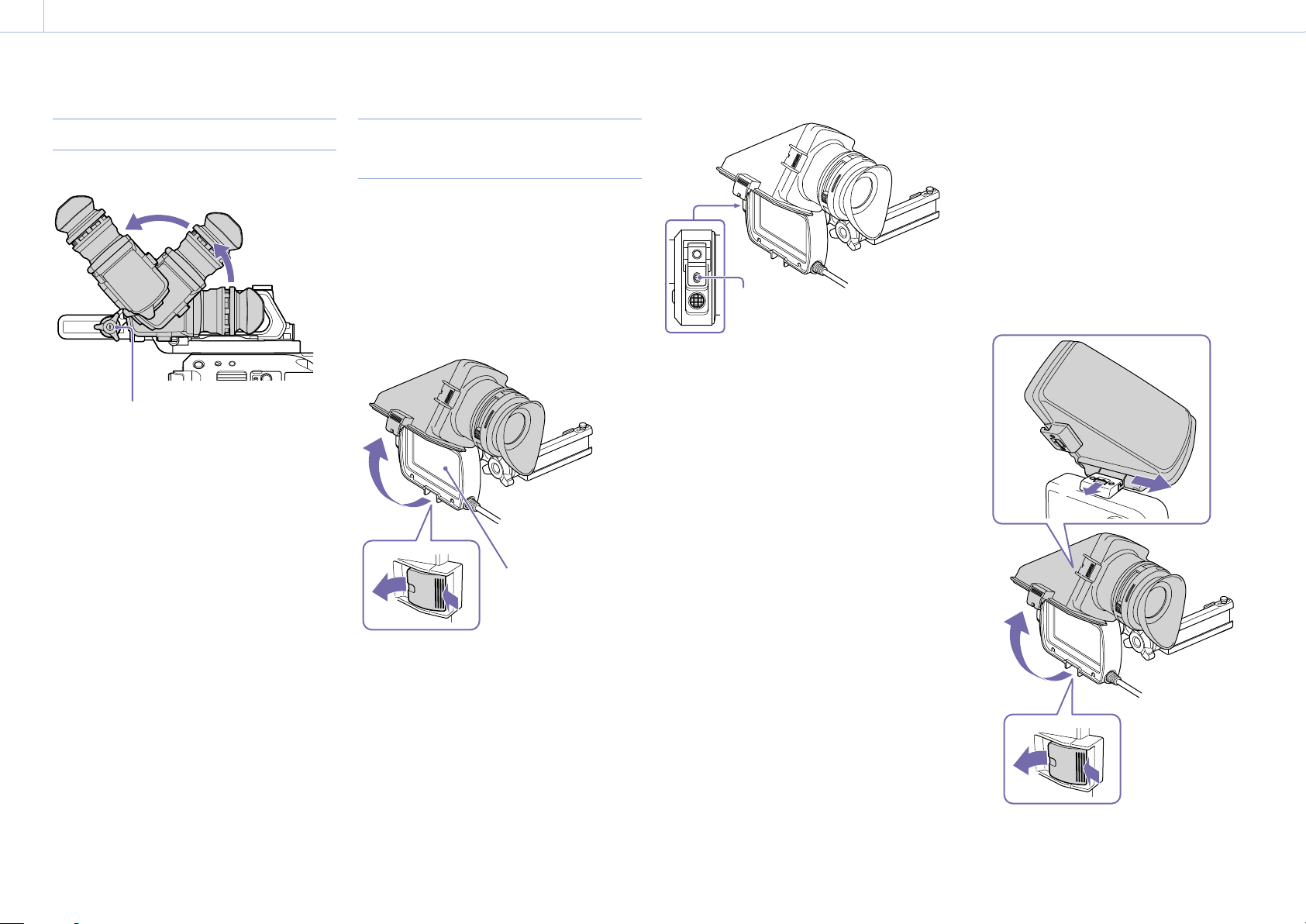
Adjusting the Angle
You can adjust the angle of the viewfinder.
Lock lever
[Notes]
If the lock lever is loose, the front/rear position may vary
when you adjust the angle. Tighten the lever and then
adjust the angle.
When adjusting the angle of the viewfinder while holding
the handle, be careful not to hit your fingers.
Raising the Viewfinder Mirror and
Eyepiece
You can view the LCD screen inside the viewfinder
or its mirrored image by lifting up the viewfinder
mirror or the eyepiece.
To lift up the viewfinder mirror
Push the clip on the bottom to release [1] and flip
up [2] the viewfinder mirror. It locks at the 120°
position.
[2]
[1]
LCD screen
MIRROR switch
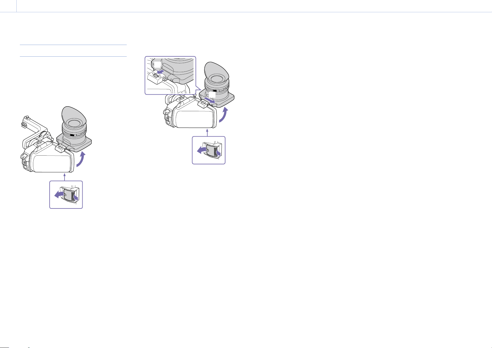
To detach the viewfinder mirror
1 Push the clip on the bottom to release.
2 Raise the viewfinder mirror and eyepiece.
3 Slide the button on the top away from the
viewfinder mirror.
4 Slide the viewfinder mirror sideways to detach
it.
3
4
In this state, the image and menu display are
flipped horizontally. You can set the MIRROR
switch on the rear side of the viewfinder to the ON
position to view the display normally.
2
1
Page 15
3. Device Adjustment and Setup: Adjusting the Viewfinder
00015
Opening/Detaching the Eyepiece
To open
Push the clip on the bottom to release [1] and flip
up [2] the viewfinder mirror.
It locks at the 120° position.
[2]
[1]
4 Slide the eyepiece sideways to detach it.
3
4
2
1
To detach
1 Push the clip on the bottom to release.
2 Flip up the eyepiece.
3 Slide the button on the top away from the
eyepiece.
Page 16

3. Device Adjustment and Setup
00016
Adjusting the Shoulder Pad
You can slide the shoulder pad forward or
backward. Adjust the position of the shoulder pad
so that the camcorder is easy to operate when
placed on your shoulder.
Shoulder pad
3
1
3
1
2
1 Loosen the two shoulder pad screws.
2 Slide the shoulder pad forward/backward to
the desired position.
3 Securely tighten the screws.
Page 17

4. Network Function Setup
00017
Compatible Terminal Devices and Functions
Compatible Terminal Devices
The network function settings of the unit support
wireless LAN connection to a smartphone, tablet,
or computer (hereinafter referred to as a “terminal
device”). The supported terminal devices, OS, and
browsers are shown in the following table.
Terminal
device
Smartphone/
tablet
Computer Microsoft Windows 7/
OS Browser
Android 5.x/6.x/7.x/8.x/9 Chrome
iOS 11.x/12.x Safari
Chrome
Microsoft Windows 8/
Microsoft Windows 10
Mac OS X 10.11
macOS 10.12/10.13/10.14
Safari
Compatible Functions with each
Network Connection
The unit uploads a file to a server and transmits
a stream of the camcorder video to a terminal
device by connecting the unit to a network.
The unit can configured and operated from the
terminal device connected to the unit via the
network. A wireless LAN, 3G/4G/LTE network,
or wired LAN can be used for the network
connection. The following functions are available
for each network connection (: Available, –:
Unavailable).
Function Network connection
Wireless LAN 3G/4G/
AP
mode
Setting and
controlling
the unit
Proxy
playback in a
browser
Uploading a
proxy file
Camcorder
remote
operation
Monitoring
live video
Streaming
live video
*1 Available by setting [Web/Cam Remote] (page 40).
*2 To use live video monitoring, you need a smartphone/
tablet on which the “Content Browser Mobile” application
is installed.
For details about network connections, see “Connecting to a
Terminal Device via Wireless LAN” (page 20) or “Connecting to
the Internet” (page 22).
–
*2
STA
mode
LTE
network
–
–
–
–
Wired
LAN
*1
*1
*1
*1
Required Devices for Network
Function
The following devices are required for each
network connection.
Network
connection
Wireless LAN USB wireless LAN module
3G/4G/LTE
network
Wired LAN USB‑RJ45 adapter
*1 Supplied with the camcorder.
*2 A 3G/4G/LTE USB modem (called “modem” in this
document) is sold separately.
*3 The USB‑RJ45 adapter is sold separately
[Notes]
Wireless LAN modules may not be available in some
countries/regions.
The frequency band for the wireless LAN module is shared
by various devices. Depending on the usage environment,
transmission speed and distance may be decreased, or
communication may be disconnected, by using other
devices.
To use a 3G/4G/LTE network, you need to contract with a
cell phone carrier.
For details about the required compatible device for each
network connection, contact your Sony dealer or Sony
service representative.
Required device
3G/4G/LTE USB modem
*3
*2
*1
Page 18

4. Network Function Setup
00018
Turning On the Network Module
1 Make sure that the unit is attached to the
camcorder correctly.
For details about attaching, see “Attaching the
Extension Unit” (page 10).
2 Set the network module power switch to the
ON position and turn on the camcorder.
The unit starts up with the same settings from
the last time it was turned off, then the STATUS
indicator lights in light green.
Page 19

4. Network Function Setup
00019
Setting the Camcorder
Setting the Camcorder to Output
Recording Control Signals
Configure the camcorder so that it outputs the
recording stop/start signals to the unit.
[Note]
The unit accepts the following signals.
1920×1080 59.94i/50i
1920×1080 29.97PsF/25PsF
1280×720 59.94P/50P
1920×1080 23.98PsF
Check whether the signal is accepted or not using the
STATUS indicator.
When SDI/HDMI Rec Control >Setting is set to
Parallel Rec in the Recording menu, a proxy file is
created with the same name as the clip recorded
on the camcorder.
Controlling the Camcorder Remotely
Via a Network
Set Wi-Fi >Wi-Fi in the System menu to Enable to
enable the wireless LAN.
[Note]
The wireless LAN module or a modem must be attached
to the unit and the network module power switch must be
turned on beforehand (page 20, 29).
Page 20

4. Network Function Setup
00020
Connecting to a Terminal Device via Wireless LAN
You can connect the unit and a terminal device via
wireless LAN.
The network function settings of the unit support
wireless LAN connection from a terminal device.
Connecting in Wireless LAN Access
Point Mode (AP Mode)
In this mode, the unit acts as an access point.
Connect to the terminal device via wireless LAN.
Smartphone/
tablet
Wireless LAN module
Camcorder + Extension unit
Attaching a wireless LAN module to the unit
Insert the wireless LAN module into the USB
connector of the unit.
Use the wireless LAN module that is supplied with
the camcorder.
[Notes]
Attach/remove a wireless LAN module while the unit is
turned off.
If a wireless LAN module that is not compatible with the
unit is attached, the STATUS indicator flashes red rapidly.
In this case, attach a compatible wireless LAN module to
the unit.
To connect
1 Set the network module power switch to the
ON position, set the WIRELESS switch to the AP
position, and turn on the camcorder.
The unit starts up in AP mode.
2 If the terminal device supports the WPS
function, press the WPS button for 3 seconds.
[Note]
It takes some time for the ST indicator to start flashing
after the unit is turned on.
The ST indicator flashes blue.
Perform the following steps within 2 minutes
after pressing the WPS button.
If the terminal device does not support the
WPS function, proceed to the next step.
3 Set the network settings > wireless LAN setting
of the terminal device to on.
For details about enabling the wireless LAN
setting of a terminal device, refer to the
operating instructions of each device.
4 Do one of the following.
If the terminal device supports the WPS
function:
Select the SSID “DIRECT_taP0:FS7BK-012345” of
the unit from the SSID list displayed on the
terminal device, then select “WPS Push Button”
from the options.
If the terminal device does not support the
WPS function:
Select the SSID “DIRECT_taP0:FS7BK-012345” of
the unit from the SSID list, then enter
“abcdefgh” for the password.
[Note]
The SSID and password of the unit are indicated on the
label of the unit. You can change the password on the
[AP Settings] screen (page 37).
5 Launch a browser on the terminal device, then
access “http://192.168.1.1:8080/”.
A login screen appears.
[Note]
Depending on the network environment, the IP address
of the unit may be “10.0.0.1” if using multiple networks.
In this case, access “http://10.0.0.1:8080/”.
6 Enter the user name and password, and tap
[OK].
[User name]: admin (default setting)
[Password]: cbk-fs7bk (default setting for the
CBK-FS7BK)
The web menu of the unit appears.
For details about the web menu, see “Web
Menu” (page 30).
[Notes]
You can change the user name and password
(page 35).
Unless otherwise noted, setting the network functions
of the unit and checking the status are performed from
the web menu (page 30). They cannot be done from
the camcorder.
Connecting in Wireless LAN Station
Mode (STA Mode)
In this mode, the unit connects to an access point
as a client. Connect to the terminal device via the
access point.
Smartphone/
tablet
Access
point
Wireless LAN module
Camcorder + Extension unit
Attaching a wireless LAN module to the unit
Insert the wireless LAN module into the USB
connector of the unit.
Page 21

4. Network Function Setup: Connecting to a Terminal Device via Wireless LAN
00021
Connecting to an access point using the WPS
function
If an access point supports the WPS function, you
can connect to the access point using simple
settings. If the access point does not support
the WPS function, see “Connecting to the access
point in STA mode without the WPS function”
(page 38).
1 Turn the access point on.
2 Set the network module power switch to the
ON position, set the WIRELESS switch to the ST
position, and turn on the camcorder.
The unit starts up in STA mode.
3 Press and hold the WPS button of the unit for 3
seconds.
The ST indicator flashes blue.
[Note]
It takes some time for the ST indicator to start flashing
after the unit is turned on.
Perform the following steps within 2 minutes
after pressing the WPS button.
6 Launch a browser on the terminal device, then
access the unit.
Enter one of the following addresses.
http://<IP address assigned to the unit by
the access point>:8080/index.html
You can check the assigned IP address of
the unit on the web page of the access
point. For details, refer to the operating
instructions of the access point.
http://FS7BK-<serial number of the
unit>:8080/index.html
“FS7BK-<serial number of the unit>” can be
changed as the host name (page 35).
7 Enter the user name and password, and tap
[OK].
[User name]: admin (default setting)
[Password]: cbk-fs7bk (default setting for the
CBK-FS7BK)
The web menu of the unit appears.
For details about the web menu, see “Web
Menu” (page 30).
[Note]
You can change the user name and password
(page 35).
4 Press the WPS button of the access point.
For details about the operation of the WPS
button, refer to the operating instructions of
the access point.
When the connection is successful, the ST
indicator lights blue and the STATUS indicator
lights light green.
[Note]
If the connection fails, the ST indicator turns off. In this
case, perform the setup again from step 1.
5 Connect the terminal device to the access
point.
For details about connecting, refer to the
operating instructions of each device.
Page 22

4. Network Function Setup
00022
Connecting to the Internet
You can connect the unit to the Internet by
attaching a modem (option) to the unit.
You can also connect to the Internet via an access
point (option) that supports 3G/4G/LTE.
Connecting Using a Modem
You can connect the unit to the Internet via
a 3G/4G/LTE network by attaching a modem
(option) to the unit.
Smartphone/
tablet
Internet
Wireless LAN
module
Camcorder + Extension unit
Modem (option)
Attaching a modem to the unit
Insert the modem (option) into the USB connector
of the unit.
When a modem that is compatible with the unit is
connected, the connection settings are configured
automatically and the unit is ready for connection
to the Internet.
For details about modems compatible with the
unit, contact your Sony dealer or Sony service
representative.
Information about the attached modem appears
on the [Modem Settings] screen (page 39).
[Notes]
Attach/remove a modem while the unit is turned off.
If a modem that is not compatible with the unit is
attached, the STATUS indicator flashes red rapidly. In this
case, attach a compatible modem to the unit.
To check modem settings
You can check the modem settings on the [Status]
screen (page 39).
Connecting in Wireless LAN Station
Mode (STA Mode)
You can connect the unit to the Internet in STA
mode via a 3G/4G/LTE compatible access point
(option) or by tethering on a smartphone/tablet.
When connecting via a 3G/4G/LTE compatible access point
Smartphone/
tablet
Internet
3G/4G/LTE
compatible
access point
(option)
Wireless LAN module
When connecting by tethering on a smartphone/tablet
Internet
Tethering on a
smartphone/
tablet
Wireless LAN module
Camcorder + Extension unit
To connect
If the access point or smartphone/tablet supports
the WPS function, connect using the procedure
in “Connecting to an access point using the
WPS function” (page 21). If the access point
or smartphone/tablet does not support the
WPS function, connect using the procedure in
“Connecting to the access point in STA mode
without the WPS function” (page 38).
Before connecting, turn the access point
or smartphone/tablet on. In the case of a
smartphone/tablet, also activate its tethering
function.
Camcorder + Extension unit
Page 23

4. Network Function Setup: Connecting to the Internet
00023
Connecting Using a LAN Cable
You can connect the unit to a network via a LAN
cable by attaching the USB-RJ45 adapter of the
CBK-NA1 Network Adapter Kit (option) to the unit.
Connect the LAN cable to the router.
For details about network settings, see “Wired LAN
Settings” (page 40).
[Note]
The CBK-NA1 and a modem cannot be used simultaneously.
Internet
Smartphone/
tablet
Wireless
LAN
module
Router
LAN cable
USB-RJ45 adapter
(option)
Camcorder + Extension unit
Page 24

5. Network Function Operations
00024
Recording the Video of a Camcorder
You can create a proxy file* from the recording/
playback video and audio signals that are input
from the SDI IN connector. The proxy file is
recorded on an SD card (option) in sync with the
recording start/stop operation of the camcorder.
* When a proxy file is recorded automatically in sync with
the camcorder recording start/stop operation, the proxy
file inherits the information and duration from the original
file. When a proxy file is recorded manually, the proxy file
does not inherit the information from the original file.
Preparation
This section describes the SD cards used for
recording, and the format setting for the proxy file.
Supported SD cards
SDXC memory cards* (Speed Class: 4 or higher)
SDHC memory cards* (Speed Class: 4 or higher)
* Referred to as “SD cards” in this document.
Recommended Sony SD cards
SDXC/SDHC UHS-I memory cards (Class 10)
SDXC/SDHC memory cards (Class 4)
SDHC memory cards (Class 10)
microSDXC/microSDHC UHS-I memory cards
(Class 10)
microSDHC memory cards (Class 4)
Operation is not guaranteed to work for all
memory cards.
[Note]
The unit cannot format an SDHC card as exFAT or an SDXC
card as FAT32.
Inserting an SD card
[Notes]
If the camcorder is turned off or the SD card is removed
while the SD card is being accessed, the integrity of data
on the card cannot be guaranteed. All data recorded on
the card may be discarded. The unit does not have any
salvage function to recover damaged material. Be sure
that the unit is turned off before you remove an SD card.
Be sure that the STATUS indicator is lit light green and
the access indicator is turned off before you turn off the
power.
Take caution to prevent the SD card from flying out when
inserting/ejecting the card.
Format setting for the recorded proxy file
The format is set to “640 × 360” (3Mbps) by
default. To change the setting, see “Proxy Format
Settings” (page 34).
Recording
The unit can record automatically in sync with the
recording start/stop operation of the camcorder
or recording can be started/stopped manually on
the unit.
Recording to an SD card starts/stops in sync
with the recording start/stop operation of the
camcorder (access indicator is lit red while
recording).
Recording on the unit stops when recording on
the camcorder stops (access indicator turns off).
You can create a proxy file of the same duration
that inherits the information of the original file
recorded on the camcorder.
[Notes]
To record a proxy file of the same duration that inherits
the information of the original file recorded on the
camcorder, you need to set [Parallel REC] in the menu of
the camcorder.
If recording is started immediately after turning the
camcorder on, the length of a proxy file that is recorded
on an SD card may differ from that of the original file
because of a short delay before the unit starts recording.
Starting/stopping recording manually
1 Open the cover of the SD card slot.
2 Insert the SD memory card into the slot with
the SD card label facing the front.
To eject the SD card
Open the cover of the SD card slot, and lightly
press the SD card in to eject the card.
To check the remaining capacity
You can check the remaining capacity on an SD
card on the [SD Card] screen (page 26).
You can start/stop recording the signal from the
camcorder manually.
You can also record manually from devices that do
not have Rec/Stop control signals embedded in
the HD-SDI signal.
In this case, the recorded file does not inherit the
information from the original file.
1 Connect a terminal device to the unit via
wireless LAN, launch a browser on the terminal
device, then access the unit (page 20).
The [Device Status] screen appears.
Page 25

5. Network Function Operations: Recording the Video of a Camcorder
00025
[Lock] switch [Rec] button
[Note]
If a screen other than the [Device Status] screen is
displayed, tap at the top left of the screen to display
the menu, then select [Device Status] to display the
[Device Status] screen.
2 Tap [Rec].
Recording starts.
To stop recording, tap [Rec] again.
You can prevent accidental operations by
setting the [Lock] switch to the right to lock
the [Rec] button.
[Note]
The [Rec] button operation is disabled while recording is
synced to the camcorder.
Using the “Content Browser Mobile” application
You can start/stop recording manually using the
“Content Browser Mobile” application. In this case,
you can control recording while viewing a stream
of the recording/playback video.
About the recorded file
The file system is FAT32 for an SDHC card and
exFAT for an SDXC card, and the file extension is
“.mp4.”
The timecode embedded in the HD-SDI signal is
also recorded simultaneously. A still image of the
first frame is also recorded.
If GPS* information is embedded in the HD-SDI
signal, the GPS information is also recorded.
* The GPS (Global Positioning System) is a navigation
system of the United States that uses high precision
satellites to provide precise location information about
wherever you are.
About the file name
When a proxy file is recorded in sync with the
camcorder
The file name is in “<file name of the original file>
+ S03.mp4” format.
In other cases
The file name is given by the recording start
timecode. For example, if recording starts at
14 hours 30 minutes 20 seconds 05 frames
(14:30:20:05) the file name will be “14_30_20_05.
mp4.” If a file exists which has the same name, a
consecutive number is appended to the file name.
Directory of the recorded file
The recorded file is stored in the “Root/PRIVATE/
PXROOT/Clip” directory.
The still picture file of the first frame is stored in the
“Root/PRIVATE/PXROOT/Thmbnl” directory, and a
GPS log file is stored in the “Root/PRIVATE/SONY/
GPS” directory.
[Notes]
When the storage capacity of an SD card is reached
during recording, “Warning” appears on the screen and
the access indicator flashes. Recording stops.
The maximum number of files that can be recorded on
an SD card is 600. When the maximum number of files is
exceeded, a warning message appears on the screen and
the access indicator flashes. At this time, the remaining
recording time becomes 0 minutes.
When an SD card error is detected during recording (write
error or read error), an error message appears on the
screen and the access indicator flashes.
Recording is disabled if an SD card is write-protected. A
warning message appears on the screen and the access
indicator flashes.
When there is a disturbance in the input signal from the
SDI IN connector and recording cannot continue, an error
message appears on the screen and the STATUS indicator
flashes.
When an SD card is not inserted, recording cannot be
performed. A warning appears on the screen.
During automatic recording using the Rec/Stop control
signals, the recording start/stop operations on the [Device
Status] screen are disabled.
Special recording modes, such as the Frame Rec and
Interval Rec functions, are not supported.
When an SDHC card is used and the file size exceeds 4 GB,
“_01” is appended to the file name and the file is split.
Checking the Files Recorded on an SD
Card
The recorded files are listed on the [SD Card]
screen. You can play a file, delete a file, or format
an SD card on the [SD Card] screen.
1 Connect a terminal device to the unit via
wireless LAN, launch a browser on the terminal
device, then access the unit (page 20).
The [Device Status] screen appears.
2 Tap > [Media Info.] > [SD Card].
The [SD Card] screen appears.
3 Double-tap the file that you want to play.
The selected file is played.
[Note]
Playback may not be available depending on the OS of your
terminal device or the version of the browser. In this case,
use “Content Browser Mobile.”
Deleting recorded files
1 Select the file that you want to delete from the
list on the [SD Card] screen.
Tap a file to select it. Tap again to cancel.
2 Tap at the top right of the screen > [Delete].
A confirmation screen appears. Tap [OK] to
delete the file. Select [Cancel] to cancel.
Page 26

5. Network Function Operations: Recording the Video of a Camcorder
00026
Formatting an SD card
If an SD card is inserted that was formatted in a
format not supported by the unit, format it using
the following procedure.
1 Tap at the top right of the [SD Card] screen >
[Format].
A confirmation screen appears. Tap [OK] to
start formatting. Select [Cancel] to cancel.
[Note]
Formatting an SD card erases all data on the card. The card
cannot be restored.
Checking the remaining capacity of an SD card
The remaining capacity is displayed at the top of
the [SD Card] screen.
You can also check the remaining capacity on the
viewfinder of a compatible camcorder.
Page 27

5. Network Function Operations
00027
Uploading a File
You can upload a proxy file that is recorded on the
unit to a server on the Internet via a 3G/4G/LTE
network, access point, or wired LAN.
If network client mode is enabled, you can upload
to the server set by the CCM.
[Note]
Files cannot be uploaded when you start streaming. If you
start streaming while uploading a file, the file upload is
stopped, and restarts when streaming is stopped.
Preparation
Connecting to the Internet
Connect the unit to the Internet using the
procedure in “Connecting to the Internet”
(page 22).
Registering the server for uploading
The server for uploading files must be registered
beforehand. For details about registering a
server, see “Register a New Server for Uploading”
(page 41).
Selecting and Uploading a File
You can upload a file that is recorded on an SD
card in the unit to a server.
1 Connect a terminal device to the unit via
wireless LAN, launch a browser on the terminal
device, then access the unit (page 20).
The [Device Status] screen appears.
2 Tap > [Media Info.] > [SD Card].
The [SD Card] screen appears.
3 Select the file you want to upload.
Tap a file to select it. Tap again to cancel.
You can double-tap to start playback to check
the contents.
4 Tap [Transfer].
The server for which [Default Setting] is set to
“On” in “Register a New Server for Uploading”
(page 41) appears.
To change the server, tap the server to display
the server list, then select a different server.
Enter the directory on the server in [Directory]
as required.
5 Tap [Transfer].
The unit starts uploading the selected file.
The STATUS indicator flashes light green
during uploading.
To cancel uploading, tap [Cancel].
[Note]
If uploading fails, the STATUS indicator flashes orange.
Checking file uploading
You can check the status of uploading on the [Job
List] screen that is displayed by tapping [Job List]
on the [SD Card] screen.
Partial transfer of a proxy file
When you use the “Content Browser Mobile”
application, you can transfer a cutout part of a file
by specifying In and Out points in the proxy file.
You can also transfer the cutout parts of multiple
files using the Storyboard.
[Notes]
Margins of up to 15 frames are added before and after the
cutout positions to proxy files that are uploaded partially.
When uploading part of a file based on the Storyboard, a
file for transferring Storyboard information to a nonlinear
editor appears in [Job List].
A General/Sony/tmp directory is created on the SD card
for uploading this file. The file is stored here temporarily,
and then it is deleted when uploading is completed.
Uploading a File in Network Client
Mode
You can upload a file to a server set by a CCM by
connecting the unit to the CCM of a Sony Network
RX Station (option) or XDCAM air in network client
mode.
1 Select the file you want to upload as described
in “Selecting and Uploading a File.”
2 Tap [Transfer].
“NCM: RX Server” appears as the destination.
3 Tap [Transfer].
The unit starts uploading the selected file to
the server set by the CCM.
[Note]
You can also set “NCM: RX Server” for the server when the
unit is not in network client mode. In this case, uploading
is paused. Uploading to the server restarts when the unit
connects to the CCM in network client mode.
Page 28

5. Network Function Operations
00028
Streaming Live Video from the Camcorder
Streaming via the Internet or Local
Network
You can transmit live video that is being shot with
the camcorder via the Internet or local network.
1 Connect a terminal device to the unit via
wireless LAN, launch a browser on the terminal
device, then access the unit (page 20).
The [Device Status] screen appears.
2 Tap > [Settings] > [Streaming Format].
The [Streaming Format] screen appears.
3 Select a preset in [Streaming] > [Preset].
4 Tap [Edit] to edit the preset.
Set the format and destination settings
(page 32).
5 Tap the [Streaming] On/Off switch to set it to
[On].
Live video transmission starts.
[Notes]
If the power is turned off, [Streaming] is set to [Off]. To
restart streaming, set [Streaming] to [On].
The streaming transmission of the unit uses the MPEG2-
TS/UDP or MPEG2-TS/RTP method. To monitor the video
and sound that are transmitted as a stream, use a device
that is compatible with these methods. For details, refer to
the operating instructions of the device.
Streaming using Sony’s QoS
Technology
You can stream high quality video by connecting
the unit to the CCM of a Sony Network RX Station
(option) or XDCAM air in network client mode.
1 Connect a terminal device to the unit via
wireless LAN, launch a browser on the terminal
device, then access the unit (page 20).
The [Device Status] screen appears.
2 Tap > [Settings] > [System Settings].
The [System Settings] screen appears.
3 Tap [Network Client Mode Settings].
4 Select a preset in [Network Client Mode
Settings] > [Preset].
5 Tap [Edit] to edit the preset.
The network client mode settings screen
appears.
6 Configure each item.
For details about settings, see “Network Client
Mode Settings” (page 36).
7 Tap the [Network Client] On/Off switch to set it
to [On].
You can arbitrarily change the display name of
the preset selected in [Preset] after editing the
preset.
Streaming with Proxy Recording Enabled
Proxy recording in network client mode is enabled
when [Proxy Recording] in [Network Client Mode
Settings] is set to [On].
You can change this setting from the Network RX
Station or XDCAM air.
[Notes]
The streaming bit rate that can be set on the Network RX
Station or XDCAM air is limited as follows depending on
the proxy recording format.
– When the proxy recording format is 1280×720
9Mbps/6 Mbps: The streaming bit rate is Very Low
(1Mbps or lower).
– When the proxy recording format is 640×360 3Mbps:
The streaming bit rate is Low (3 Mbps or lower).
The proxy format cannot be changed while in network
client mode. To change the proxy format, first turn
network client mode off.
8 Tap [OK].
Network client mode is activated and the unit
connects to the Network RX Station or XDCAM
air. Live video transmission is started from the
Network RX Station or XDCAM air. For details,
refer to the operating instructions of the
Network RX Station or the Help of XDCAM air.
Page 29

5. Network Function Operations
00029
Controlling the Camcorder Remotely
You can control the camcorder remotely by
accessing the Wi-Fi remote control that is built into
the camcorder.
1 Connect a terminal device to the unit via
wireless LAN, launch a browser on the terminal
device, then access the unit (page 20).
The [Device Status] screen appears.
2 On the camcorder, set [Wi-Fi] >[Wi-Fi] in the
[System] menu to [Enable].
3 Tap > [Cam Remote Control].
The remote control screen appears.
A password entry screen may appear. Enter the
password previously configured using the
menu of the camcorder.
[Notes]
You can control the camcorder remotely via wired LAN
by connecting the unit and the terminal device via a
wired LAN network and setting [Wired LAN Settings] >
[Web/Cam Remote] to [On] (page 40).
Setting the network module power switch to the
STANDBY position and turning on the camcorder
disables remote operation of the camcorder. Configure
the setting in step
2.
Page 30

6. Network Function Setup Using the Web Menu
00030
Web Menu
The web menu of the unit is displayed by
accessing the unit from a browser on a terminal
device that is connected to the unit via wireless
LAN. You can check the status of the unit,
configure settings, and start/stop recording
manually from the web menu.
Initial Screen
When the unit is connected to a terminal device
and the unit is accessed from a browser on
the terminal device, the [Device Status] screen
appears, displaying the status of the unit and
control shortcut buttons.
Displays the menu for selecting setup screen.
Shortcut buttons for the [SD Card]
screen and [Settings] screen
Displays the status of the unit.
Status of the unit
[Status]
[Streaming]
[Monitoring]: [Streaming] is set to [Off]
[Running]: [MPEG2-TS/UDP] or [MPEG2-TS/RTP]
[Stop]: Not streaming
[Initializing]: In preparation
Error indication: Destination Address Error, No
Internet Access
[Proxy]
[Recording]: During proxy file recording
[Stop]: Not recording
[Remain]: Remaining recording time of the SD
card
[Warning/Error]: Warning/Error indication (“Wxx-
xxx” is a warning number. “Exx-xxx” is an error
number (page 47))
[Rec]: Recording start button (page 24)
[Lock]: Lock switch (page 24)
When network client mode (page 36) is on,
[Streaming] and [Proxy] change to the following
items.
[Network Client]
[Connected to CCM Name]: Connection
successful
Error indication: Destination Address Error,
Authentication Failed, No Internet Access,
Certificate is not yet valid, Certification Error
In this case, the STATUS indicator flashes orange
slowly.
[Streaming]
[Running]: During streaming
[Stop]: Not streaming
[Initializing]: In preparation
[Proxy]
[Stop]: Not recording (when [Proxy Recording] is
set to [On])
[Recording]: During proxy file recording (when
[Proxy Recording] is set to [On])
[Disabling]: Recording disabled (when [Proxy
Recording] is set to [Off])
[Note]
If “Certificate is not yet valid” appears, the date may be set to
an invalid value. Check the date setting.
[Network]
[Wireless LAN IP Address]: IP address of the unit
[Internet Access]: Internet connection
[Modem]: Via modem
[Wi-Fi Router]: Via wireless LAN access point
[Unavailable]: Connection not available
[Modem Status]: Modem status
[Connected]: Connected
[Connecting]: Attempting to connect
[Disconnected]: Disconnected
[USB-RJ45 Connected]: USB-RJ45 adapter is
attached
[Internet IP Address]: Internet-facing IP address
(only when the IP address can be retrieved)
[Hardware]
[Serial Number]: Serial number of the unit
[Camcorder]: Status of connection with the
camcorder
[Connected]: Connected
[Firmware]
[Firmware Version]: Software version of the
network module
Page 31

6. Network Function Setup Using the Web Menu: Web Menu
00031
Setup Menu
The setup menu is displayed by tapping at the
top left of the screen. Tap the item that you want
to set.
[Settings]
Displays the screen for configuring the unit.
[Wireless Adapter]
[Streaming Format]: Streaming format settings
(page 32)
[Proxy Format]: Proxy format settings
(page 34)
[System Settings]: System settings (page 35)
[Wireless LAN]
[AP Settings]: Access point settings (page 37)
[Station Settings]: Wireless LAN settings
(page 38)
[Status]: Wireless LAN status (page 38)
[Modem]
[Modem Settings]: Modem settings (page 39)
[Status]: Modem status (page 39)
[Wired LAN]
[Wired LAN Settings]: Wired LAN settings
(page 40)
[Status]: Wired LAN status (page 40)
[Note]
[Modem] changes to [Wired LAN] when the USB-RJ45
adapter is attached.
[Upload Settings]
Upload settings (page 41)
[Note]
When the [Settings] screen is displayed, you can display the
following sub-screens.
Wireless LAN settings
Access point settings
System settings
Proxy settings
Streaming settings
Upload settings
Modem/wired LAN status*
Modem/wired LAN settings*
Wireless LAN status
* When the USB-RJ45 adapter is attached.
[Media Info]
Displays the screen for displaying the status of
the media, or for selecting the file to upload
(page 27).
[SD Card]: SD card that is inserted into the card slot
of the unit.
[Job List]
Displays the [Job List] screen for managing the
uploading of files (page 43).
[Cam Remote Control]
Displays the Wi-Fi remote control by accessing the
camcorder (page 29).
[OSS Information]
Displays copyright information.
Page 32

6. Network Function Setup Using the Web Menu
00032
Streaming Format Settings
You can set the format for the stream that is
monitored on the terminal device via wireless LAN,
and the format/transmission destination for the
stream via Internet/wired LAN.
Video
AVC/H.264 Main Profile, 4:2:0 Long GOP
The size is selected by the following settings.
Audio
AAC-LC compression
Sampling frequency: 48kHz
Bit rate: 128kbps for stereo
The playback channel is selected by the
following settings.
Monitoring Settings
You can set the format when monitoring on a
terminal device.
[Size]
Sets the size and bit rate of the video for
monitoring.
[480×270]: 1Mbps (VBR)
[480×270]: 0.5Mbps (VBR)
[Note]
This bit rate is the average value. The actual bit rate may be
higher than the average value.
[Frame Rate]
Displays the frame rate of the video. This is set by
the signal that is input from the SDI IN connector.
[23.98fps]: 23.975fps
[25fps]: 25fps
[29.97fps]: 29.97fps
[50fps]: 50fps
[59.94fps]: 59.94fps
[Note]
24fps is not supported.
[Bit Rate]
Displays the bit rate of the video.
[1Mbps (VBR)]: 480×270
[0.5Mbps (VBR)]: 480×270
Streaming Settings
You can set the format and transmission
destination for streaming. Settings are stored as a
preset (up to three presets).
[On/Off]
Switches streaming transmission on/off.
[Note]
The monitoring function is not available when this item is
set to [On].
[Preset]
Select a preset from [Preset 1] to [Preset 3]. The
preset can be edited by tapping [Edit].
To edit a preset
1 Select the preset you want to edit in [Preset].
2 Tap [Edit].
The preset editing screen appears.
3 Configure the following items.
[Type]
Selects the type of video for streaming from
[MPEG2-TS/UDP] and [MPEG2-TS/RTP].
[Size]
Sets the video size for streaming.
When [HD/SD Auto] is selected, this is set by
the signal that is input from the SDI IN
connector.
[Bit Rate]
Sets the bit rate for streaming.
The selectable items differ depending on the
[Size] setting.
When using a network bandwidth of 500kbps
or lower, select the following:
[Size] 480×270: [Bit Rate] 0.3Mbps (Mono L)/
0.3Mbps (Mono R)
[Size] 480×270: [Bit Rate] 0.2Mbps (Mono L)/
0.2Mbps (Mono R)
[Size] 320×180: [Bit Rate] 0.2Mbps (Mono L)/
0.2Mbps (Mono R)
In this case, the video frame rate is 10fps, the
audio sampling frequency is 48kHz, and the
audio bit rate is 56kbps Mono.
[Destination Address]
Enter the address of the server for streaming
transmission.
[Destination Port]
Enter the port number of the destination
server that is used for streaming.
4 Tap [OK].
The settings are applied, and the preset
settings are displayed in [Properties].
To cancel, tap [Cancel].
[Notes]
Data may leak because the video/audio data is transferred
as-is via the Internet. Check that the transmission
destination can receive the streaming data. The data may
be sent to an unintended party if the address or other
settings are incorrect.
Not all frames may be played depending on the network
status.
The picture quality may deteriorate in scenes with quick
motion.
Not all frames may be played when the stream is set to
a large size with a small bit rate. To reduce this, select a
smaller size in [Size].
Page 33

6. Network Function Setup Using the Web Menu: Streaming Format Settings
00033
Audio Channel Settings
[Audio Channel Select]
Selects the audio channel.
[Ch-1 & Ch-2]: Audio of channels 1 and 2 (default
setting)
[Ch-3 & Ch-4]: Audio of channels 3 and 4
[Notes]
The channel on the left of the item name becomes the
left channel, and the channel on the right of the item
name becomes the right channel.
[Size] 480×270: [Bit Rate] 0.3Mbps (Mono L)/0.3Mbps
(Mono R)
[Size] 480×270: [Bit Rate] 0.2Mbps (Mono L)/0.2Mbps
(Mono R)
[Size] 320×180: [Bit Rate] 0.2Mbps (Mono L)/0.2Mbps
(Mono R)
When the settings above are made, the following are
selected.
For Mono L
Ch-1 from [Ch-1 & Ch-2]
Ch-3 from [Ch-3 & Ch-4]
For Mono R
Ch-2 from [Ch-1 & Ch-2]
Ch-4 from [Ch-3 & Ch-4]
Page 34

6. Network Function Setup Using the Web Menu
00034
Proxy Format Settings
You can set the format of the proxy file that is
recorded on the SD card of the unit.
Video
XAVC® Proxy (AVC/H.264 Main Profile, 4:2:0 Long
GOP)
The size is selected by the following settings.
Audio
AAC-LC compression
Sampling frequency: 48kHz
Bit rate: 128kbps for stereo
The playback channel is selected by the
following settings.
[Size]
Set the size and bit rate of the video for the proxy
file.
[HD/SD Auto]: 9Mbps (VBR)
[HD/SD Auto]: 6Mbps (VBR)
[1280×720]: 9Mbps (VBR)
[1280×720]: 6Mbps (VBR)
[640×360]: 3Mbps (VBR)
[480×270]: 1Mbps (VBR)
[480×270]: 0.5Mbps (VBR)
[Notes]
This bit rate is the average value. The actual bit rate may
be higher than the average value.
When [HD/SD Auto] is selected, the format is
automatically set by the signal that is input from the SDI
IN connector.
Proxy recording is not available when the SDI input signal
is 23.98PsF.
The proxy file recorded with [HD/SD Auto] may not be
playable in a web browser or Content Browser Mobile.
Insert the SD card on which the proxy file is recorded
directly into a computer play the video.
[Frame Rate]
Displays the frame rate of the video. This is set by
the signal that is input from the SDI IN connector.
[23.98fps]: 23.975fps
[25fps]: 25fps
[29.97fps]: 29.97fps
[50fps]: 50fps
[59.94fps]: 59.94fps
[Note]
24fps is not supported.
[Bit Rate]
Displays the bit rate of the video.
[9Mbps (VBR)]: HD/SD Auto / 1280×720
[6Mbps (VBR)]: HD/SD Auto / 1280×720
[3Mbps (VBR)]: 640×360
[1Mbps (VBR)]: 480×270
[0.5Mbps (VBR)]: 480×270
[Audio Channel Select]
Selects the audio channel for recording.
[Ch-1 & Ch-2]: Audio of channels 1 and 2 (default
setting)
[Ch-3 & Ch-4]: Audio of channels 3 and 4
[Note]
The channel on the left of the item name becomes the left
channel, and the channel on the right of the item name
becomes the right channel.
Page 35

6. Network Function Setup Using the Web Menu
00035
System Settings
You can set the date/time and the host name/user
name/password for accessing the web menu of
the unit.
Date and time settings
User name and password settings
Network client mode
Update firmware
For details about dating, see “Updating the Unit”
(page 44).
settings
User Name and Password Settings
You can set the host name, user name, and
password for accessing the web menu of the unit
from a browser on a terminal device.
Tap [User/Password] on the [System Settings]
screen to display the user input screen.
[Note]
Do not use [Camcorder User] and [Camcorder Password].
When finished, tap [OK] to apply the settings. To
cancel, tap [Cancel].
Date and Time Settings
You can set the date and time.
Tap [Date & Time] on the [System Settings] screen
to display the user input screen.
When finished, tap [OK] to apply the settings. To
cancel, tap [Cancel].
[Note]
The retention period for the date and time settings is
about two months. If the retention period is exceeded,
the date and time settings returns to the default of
2019:05:01:00:00:00.
[Adjust Date on boot]
When set to [On], the date and time are updated
automatically by accessing the NTP server when
the unit is turned on (only when the unit is
connected to the Internet).
[Time Zone]
Select the time zone from the list.
[Summer Time]
When set to [On], summer time is activated (+1
hour).
[Host Name]
Enter the host name of the unit.
(Default setting: FS7BK- + serial number)
[User]
Enter the user name of the unit.
(Default setting: admin)
[Password]
Enter the password of the unit.
Enter the password to confirm the password.
(Default setting: cbk-fs7bk)
[Notes]
Alphanumeric characters and ! % * + , - . = _ characters are
valid for [User] and [Password].
From a security standpoint, it is recommended that you
set a password with a sufficiently long character string
that is hard to guess by others, and that you store it safely.
[Date & Time]
[Year]: Year
[Month]: Month
[Day]: Day
[Hour]: Hour (24-hour format)
[Min.]: Minute
[Sec.]: Second
[NTP Server Name]
Adjusts the date and time automatically by
connecting to an NTP server.
Enter the host name of the NTP server that you
want to connect to in the entry field.
[Adjust Date]: Tap to access the NTP server and
update the date and time automatically.
Page 36

6. Network Function Setup Using the Web Menu: System Settings
00036
Network Client Mode Settings
You can set network client mode settings. Settings
are stored as a preset (up to three presets).
Tap [Network Client Mode Settings] on the
[System Settings] screen to display the setup
screen.
When finished, tap [OK] to apply the settings. To
cancel, tap [Cancel].
[Preset]
Select a preset from [Preset 1] to [Preset 3]. The
preset can be edited by tapping [Edit].
[CCM Port]
Displays the current setting.
[Notes]
If network client mode is set to on during streaming or
monitoring, a confirmation dialog appears.
If [OK] is selected, the unit enters network client mode
and those operations are canceled.
When HD/SD Auto (9 Mbps) or HD/SD Auto (6 Mbps) is
selected for the Proxy Format, [Proxy Recording] cannot
be set. If set to [On], the value is retained, but recording is
not performed.
To edit a preset
1 Select the preset you want to edit in [Preset].
2 Tap [Edit].
The preset editing screen appears.
[CCM Port]
Enter the port number of the connected CCM.
[User]
Enter the user name.
[Password]
Enter the password.
4 Tap [OK].
The settings are applied, and the preset
settings are displayed in [Properties].
To cancel, tap [Cancel].
[Network Client]
When set to [On], network client mode is enabled,
and the unit starts connecting to the CCM that is
selected in [Preset].
[Auto Start]
When set to [On], the unit starts up with network
client mode enabled when the unit is turned on
the next time.
[Proxy Recording]
Displays the current setting.
[CCM Address]
Displays the current setting.
3 Configure the following items.
[Display Name]
Enter the name displayed in the list.
[Proxy Recording]
When set to [On], proxy recording is enabled
and the unit enters network client mode.
[Note]
The streaming bit rate is limited when proxy recording
is enabled.
[CCM Address]
Enter the address of the connected CCM.
Enter the destination URL when using XDCAM
air.
Page 37

6. Network Function Setup Using the Web Menu
00037
Access Point Settings (AP Settings)
You can configure the unit for use as an access
point.
[WLAN Device Name]
Displays the name of the used wireless LAN
module.
[Channel Select]
You can change the wireless LAN channel.
[Auto] selects Ch1 to Ch11 automatically, and
[Channel Select] allows you to set Ch1 to Ch11
manually.
When a 5GHz compatible wireless LAN module is
attached, the [Auto (5GHz)] item is added.
[Note]
Depending on the wireless LAN module, [Auto (5GHz)] may
not be displayed. It also is not displayed on models for the
country/region that prohibits the use of the 5GHz band
outdoors. Check if the wireless LAN module is supported in
the country/region where the unit is used. For details, refer
to the operating instructions of the wireless LAN module.
[SSID]
Displays the SSID of the unit.
[Key]
You can change the password of the unit.
8 to 63 alphanumeric characters can be used.
Page 38

6. Network Function Setup Using the Web Menu
00038
Wireless LAN settings (Station Settings)
You can configure settings for connecting to a
wireless LAN.
[Host Name]
Displays the host name of the unit.
[SSID]
Enter the SSID of the access point to which the
unit connects.
WPA and WPA2 are available for the authentication
method.
When a 5GHz compatible wireless LAN module
is attached, the unit can connect to a 5GHz
compatible access point.
[Key]
Enter the password for the access point.
[DHCP]
Enables DHCP.
When set to [On], an IP address is assigned to the
unit automatically.
To assign an IP address to the unit manually, set
to [Off].
[IP Address]
Enter the IP address of the unit. This setting is
available only when [DHCP] is set to [Off].
[Subnet mask]
Enter the subnet mask of the unit. This setting is
available only when [DHCP] is set to [Off].
[Gateway]
Enter the gateway for the access point. This setting
is available only when [DHCP] is set to [Off].
[DNS Auto]
Sets whether to acquire DNS automatically.
When set to [On], the DNS server address is
acquired automatically.
[Primary DNS Server]
Enter the primary DNS server for the access point.
This setting is available only when [DNS Auto] is
set to [Off].
[Secondary DNS Server]
Enter the secondary DNS server for the access
point. This setting is available only when [DNS
Auto] is set to [Off].
[Submit]
Applies the wireless LAN settings.
Connecting to the access point in STA mode
without the WPS function
1 Connect the terminal device to the unit in AP
mode (page 20).
2 Set the items on the [Station Settings] screen.
Configure the settings to match the settings of
the access point to which to connect.
For details about the access point settings,
refer to the operating instructions of the
access point.
3 Tap [Submit].
The configured items are applied.
4 Set the WIRELESS switch to the ST position.
The unit connects to the access point in STA
mode. Access the unit from a terminal device
from step
using the WPS function” (page 21).
5 of “Connecting to an access point
Checking the Wireless LAN Settings
Display the screen for checking the wireless LAN
settings by tapping [Wireless LAN] > [Status].
The displayed items differ depending on the
wireless LAN mode of the unit.
AP mode
STA mode
Page 39

6. Network Function Setup Using the Web Menu
00039
Modem Settings
You can configure settings for connecting to the
Internet when using a modem (option) connected
to the unit.
When a modem that is compatible with the unit
is connected, the connection settings are made
automatically, and are displayed on the [Modem
Settings] screen. (The unit is ready to connect to
the Internet.)
When a modem is not connected, values are not
displayed.
For details about modems compatible with the
unit, contact your Sony dealer or Sony service
representative.
[Note]
When the USB-RJ45 adapter (option) is attached, the
[Modem Settings] screen does not appear.
Checking the Modem Settings
Display the screen for checking the modem
settings by tapping [Modem] > [Status].
Page 40

6. Network Function Setup Using the Web Menu
00040
Wired LAN Settings
You can configure settings for connecting to a
network using the USB-RJ45 adapter (option) and
a LAN cable.
[Note]
The [Wired LAN Settings] screen appears only when the
USB-RJ45 adapter (option) is attached.
[DHCP]
Enables DHCP.
When set to [On], an IP address is assigned to the
unit automatically.
To assign an IP address to the unit manually, set
to [Off].
[IP Address]
Enter the IP address of the unit. This setting is
available only when [DHCP] is set to [Off].
[DNS Auto]
Sets whether to acquire DNS automatically.
When set to [On], the DNS server address is
acquired automatically.
[Primary DNS Server]
Enter the primary DNS server for the router.
This setting is available only when [DNS Auto] is
set to [Off].
[Secondary DNS Server]
Enter the secondary DNS server for the router.
This setting is available only when [DNS Auto] is
set to [Off].
[Web/Cam Remote]
Set the access permission for the web menu of the
unit or the Wi-Fi remote control of the camcorder
when using the USB-RJ45 adapter. Access is
permitted by setting to [On].
[Note]
We recommend that [Web/Cam Remote] be set to [On]
only when the wired LAN network is not connected to
the Internet to prevent unauthorized access. If the unit
is connected to the Internet, be sure to confirm that the
connected network is protected securely.
[Submit]
Applies the Ethernet settings.
Checking the Wired LAN Settings
Display the screen for checking the wired LAN
settings by tapping [Wired LAN] > [Status].
[Subnet mask]
Enter the subnet mask of the unit. This setting is
available only when [DHCP] is set to [Off].
[Gateway]
Enter the gateway for the access point. This setting
is available only when [DHCP] is set to [Off].
Page 41

6. Network Function Setup Using the Web Menu
00041
Upload Settings
You can register a server for uploading a proxy
file that is recorded on the unit, and change the
registered server.
Delete registered server
Select server
Turn auto transfer function on/off
“Sony Ci” and “NCM: RX Server” are registered, and
“Sony Ci” is set as the default server.
Sony Ci is part of the “Media Cloud Services”
provided by Sony. You can upload files to the Sony
Ci cloud service.
[Notes]
Not supported in some regions.
To use Sony Ci, registration is required. For details, visit
www.SonyMCS.com/wireless.
In addition, refer to the following sites for the privacy
policy of Sony Ci.
Terms of service
https://www.sonymcs.com/terms/
Use policy
https://www.sonymcs.com/use/
Privacy policy
https://www.sonymcs.com/privacy/
You can set “NCM: RX Server” as the default server. When
network client mode is disabled, uploading is paused.
Change server settings
Register a server
To register with “Sony Ci”
1 Check that “Sony Ci” is displayed on the
[Upload Settings] screen, then tap [Edit].
The Sony Ci setup screen appears.
2 Enter the user name in [User] and the
password in [Password].
For more details, visit www.SonyMCS.com/
wireless.
3 Tap [Link].
[Note]
“Link” is an operation that associates the user with the
unit. An Internet connection is required to execute Link.
After a few moments, a completion message appears.
4 Tap [OK].
[Note]
After registering with Sony Ci, [Unlink] will appear on the
setup screen. If you tap [Unlink], the current user account
will be unlinked, and then you can link to a different user
account.
Register a New Server for Uploading
Display the setup screen by tapping [Create New].
When finished, tap [OK] to apply the settings. To
cancel, tap [Cancel].
[Default Server]
When set to [On], the file server is set as the default
(displayed as the preferred server in the list when
uploading).
[Display Name]
Enter the server name displayed in the list.
[Service]
Displays the server type.
[FTP]: FTP server
[Host Name]
Enter the address of the server.
[Note]
If using a port other than the default port 21, add “:123”
(example) after the address.
[Password]
Enter the password.
[PASV Mode]
Turns PASV mode on/off.
[Destination Directory]
Specifies the directory for uploading.
[Note]
If invalid characters are entered in a directory name, the
directory is not created and the file is uploaded directly to
the top directory.
[Using Secure Protocol]
Sets whether to execute secure FTP transfer.
[Load Certification]
Loads an intermediate CA certificate.
Displayed only when [Using Secure Protocol] is set
to [On].
[Notes]
We recommend using FTPS because FTP communication
is not encrypted.
An intermediate CA certificate including a root CA
certificate is required.
The loaded certificate is in PEM format and named
“certification.pem.” It is stored in the root directory of an
SD card.
[User]
Enter the user name.
Page 42

6. Network Function Setup Using the Web Menu: Upload Settings
00042
Changing the Registered Server
Settings
Tap [Edit] after selecting the server for which
you want to change the settings on the [Upload
Settings] screen. Change the settings on the
screen, as required.
For details about settings, see “Register a New
Server for Uploading” (page 41).
Deleting a Registered Server
Tap [Delete] after selecting the server which you
want to delete on the [Upload Settings] screen. A
confirmation screen appears. Tap [OK] to delete
the server and return to the previous screen.
Starting File Transfer Automatically
after Recording Ends
Set [Auto upload] to [On] to automatically start
transferring the file that is stored on an SD card
after recording ends.
Restarting File Transfer (Resume
Function)
If file transfer fails, the file transfer resumes from
where the file transfer had failed.
[Notes]
This function is available only on a server that supports
the resume function.
When file transfer fails, the STATUS indicator flashes
orange.
Page 43

6. Network Function Setup Using the Web Menu
00043
Checking File Uploading (Job List)
You can check the list of the files to be uploaded,
the file that is being uploaded, cancel or start file
uploading, and delete a file from the file list.
[Total]: Progress of all the files to be uploaded.
[Status]: Progress of the file that is currently being
uploaded.
[Transfer data rate]: Transfer rate (estimated value)
[Remain time]: Remaining time (estimated value)
[Note]
When “NCM: RX Server” is set as the default server and
network client mode is disabled, “NCM: (Unknown)” appears
as the destination and “Waiting” appears in [Status]. When
connection is established after connecting to CCM in
network client mode, the destination changes (example:
“NCM: My FTP Server”) and uploading starts.
To cancel or resume uploading, or delete a file
from the file list
1 Select the file.
2 Tap at the top right of the screen.
Select the following items.
[Abort selected]: Cancel uploading the
selected file.
[Delete from list]: Delete the selected file from
the list.
[Start selected]: Start uploading the selected
file.
[Clear completed]: Delete all the uploaded files
from the list.
Page 44

7. Maintenance
00044
Updating the Unit
The unit uses two types of software; software that
provides the same functionality as the XDCA-FS7,
and software that provides the network functions.
The XDCA-FS7 equivalent functions are updated
using the UTILITY SD card slot of the camcorder
and executing [Version] >[Ext. Unit Version Up] in
the [System] menu of the camcorder. For details,
refer to the instructions supplied with the updater
file.
Updating the Network Functions
The network functions are updated using the SD
card slot of the extension unit.
Even though the unit is updated, the settings of
the unit are retained and you can continue to use
the unit as-is. However, the [Job List] items are
reset.
1 Save the network functions updater file to the
root directory of an SD card.
2 Insert the SD card into the SD card slot of the
extension unit, and turn on the camcorder.
3 Connect a terminal device to the unit via
wireless LAN, launch a browser on the terminal
device, then access the unit (page 20).
The [Device Status] screen appears.
4 Tap > [Settings] > [System Settings].
The [System Settings] screen appears.
6 Tap [Update] to load the firmware package file
from the SD card.
While updating, the message “Firmware
updating It takes several minutes, please wait.”
appears.
7 The unit restarts, and the STATUS indicator and
ST indicator flashes.
While restarting, the web menu does not
appear in the browser.
[Note]
If you turn the camcorder off or set the network module
power switch to the STANDBY position while updating,
the update will fail. In this case, repeat the steps from
the beginning.
8 Turn the camcorder off, and then on again.
The unit starts with the new version of the
firmware.
You can check the version on the [Device
Status] screen (page 30).
Change the camcorder settings as required
(page 19).
If updating fails
Outputting the log file
If an abnormality occurs in the unit, a log can be
recorded on an SD card. The log file is encrypted,
and cannot be checked by the customer. Contact
a Sony service representative and submit the log
file as necessary.
Resetting Network Function Settings
to Factory Defaults
You can reset the network function settings to the
factory default settings.
1 Press and hold the RESET button for 3 seconds.
The STATUS indicator turns off, and then the
unit restarts.
Change the camcorder settings as required
(page 19).
5 Tap [Firmware Update].
The [Firmware Update] screen appears.
If updating fails, the STATUS indicator flashes red.
In this case, repeat the steps from the beginning.
Page 45

8. Appendix
00045
Usage Precautions
Use and Storage Locations
Store in a level, ventilated place. Avoid using or
storing the unit in the following places.
In excessive heat or cold (operating temperature
range: 0°C to 40°C (32°F to 104°F))
Remember that in summer in warm climates,
the temperature inside a car with the windows
closed can easily exceed 50°C (122°F).
In damp or dusty locations
Locations exposed to rain
Locations subject to violent vibration
Near strong magnetic fields
Close to radio or TV transmitters producing
strong electromagnetic fields.
In direct sunlight or close to heaters for
extended periods
Do not subject to strong shocks
Do not drop the unit or subject it to strong shocks.
The unit may be damaged.
Do not wrap in a cloth or other covering during
operation
Internal temperatures may rise, causing a
malfunction.
Cleaning
Clean the cabinet and panels by wiping lightly
with a soft, dry cloth. If the unit is very dirty, use a
cloth dampened with a small amount of neutral
detergent, then wipe dry. Avoid the use of volatile
solvents such as thinners, alcohol, benzene, and
insecticides. They may damage the surface finish
or cause it to peel off.
Transport
When transporting the unit by truck, ship, or air,
or whenever it may be handled as freight, always
pack it in the original protective packaging, after
removing the camcorder, camera adapter, and
cables from the camcorder support.
Moving
Before moving the camcorder, remove the unit
from the camcorder support. It the camcorder is
moved while the unit is attached, the unit may fall
and may cause an injury.
Condensation
If the unit is suddenly taken from a cold to a warm
location, or if ambient temperature suddenly
rises, moisture may form on the outer surface of
the unit and/or inside of the unit. This is known
as condensation. If condensation occurs, turn off
the unit and wait until the condensation clears
before operating the unit. Operating the unit while
condensation is present may damage the unit.
File Fragmentation
If pictures cannot be recorded/reproduced
properly, try reformatting the SD card. After
repeated recording/playback with an SD card
for an extended period, files on the SD card
may become fragmented, preventing proper
recording/storage. In such a case, make a backup
of clips from the SD card, then reformat it.
Page 46

8. Appendix
00046
Troubleshooting
This section describes measures you can take when problems occur in the following situations.
Wireless LAN connection
Internet connection
Wired LAN connection
[Note]
Obstructions and electromagnetic interference between the unit and a wireless LAN access point or terminal device, or the
ambient environment (such as wall materials) could shorten the communication range or prevent connections altogether. If
you experience these problems, check the connection/communication status after moving the camcorder to a new location or
bringing the unit and access point/terminal device closer together.
Wireless LAN Connection
Problem Resolution
The STATUS indicator flashes red, and
wireless LAN cannot be used.
The terminal device cannot access the
unit.
Cannot log in to the unit. Check the user name and password that you set.
The web menu of the unit does not
appear.
The Wi-Fi Remote screen of the
camcorder does not appear.
The connected wireless LAN module may not be compatible with
the unit.
For details about compatible wireless LAN modules, contact your
Sony dealer or Sony service representative.
Check the wireless LAN connection settings (such as the IP
address).
The communication setting between the access point and client
may be invalid. For details, refer to the operating instructions of
the access point.
Check the IP address setting.
Check that the port number (:8080) is added to the IP address.
Check that the USB cable is connected.
Check that the firmware version of the camcorder is supported
by the unit.
Internet Connection
Problem Resolution
The STATUS indicator flashes red, and
the modem cannot be recognized.
The STATUS indicator flashes orange,
and file uploading fails.
The STATUS indicator lights orange, and
files cannot be uploaded.
The connected modem may not be compatible with the unit.
For details about compatible modems, contact your Sony dealer or
Sony service representative.
The user name and password of the server may not be correct.
Enter the correct user name and password.
The 3G/4G/LTE signal strength may be bad. Change the location
and try again.
Wired LAN Connection
Problem Resolution
“E03-007 IP Address Setting Error”
appears.
Functions via the Internet do not work. If the USB-RJ45 adapter is attached to the unit and a wired LAN is
A conflict between the network address for the wireless LAN and IP
address setting may have occurred.
Change the address manually, or change the setting of the network
router.
not connected to the Internet, functions via the Internet will not
work even if the wireless adapter is connected to the Internet in
STA mode.
In this case, remove the USB-RJ45 adapter and connect to the
Internet in STA mode only.
Page 47

8. Appendix
00047
Error/Warning Indications
If an error is detected on the unit, an error message will appear on the [Device Status] screen.
Type Error/warning ID Description STATUS indicator Access indicator
Hardware E01-003 Device Error Flashes red rapidly –
E01-004 3G/4G Device Error Flashes orange
rapidly
E01-005 Firmware update error Flashes red slowly –
AV E02-002 SDI Signal Error Flashes red slowly –
Communication E03-001 Communication Error Lit orange –
E03-002 Not supported device Flashes red rapidly –
E03-003 File Transfer Error Flashes orange
slowly
E03-004 Firmware update error Flashes red slowly –
E03-005 Authentication failed* Flashes orange
slowly
E03-006 Server Capacity Over Flashes orange
slowly
E03-007 IP Address setting error Lit orange –
E03-008 Certification Error Flashes orange
slowly
Media W04-001 No Media – Flashes red
W04-002 Media Full – Flashes red
E04-003 Read Error – Flashes red
E04-004 Write Error (excluding
capacity over)
W04-005 Locked Media – Flashes red
W04-006 Clips Full (reached 600 clips) – Flashes red
E04-007 Not supported media – Flashes red
W04-008 Media Near Full – –
W04-009 Clips Near Full – –
W04-010 Last Clip Recording – –
* Sony Ci authentication expired, or FTP server authentication failed.
– Flashes red
–
–
–
–
–
Page 48

8. Appendix
00048
Licenses
MPEG‑4 AVC
THIS PRODUCT IS LICENSED UNDER THE AVC
PATENT PORTFOLIO LICENSE FOR THE PERSONAL
USE OF A CONSUMER OR OTHER USES IN WHICH IT
DOES NOT RECEIVE REMUNERATION TO
(i) ENCODE VIDEO IN COMPLIANCE WITH THE AVC
STANDARD (“AVC VIDEO”) AND/OR
(ii) DECODE AVC VIDEO THAT WAS ENCODED BY
A CONSUMER ENGAGED IN A PERSONAL ACTIVITY
AND/OR WAS OBTAINED FROM A VIDEO PROVIDER
LICENSED TO PROVIDE AVC VIDEO.
NO LICENSE IS GRANTED OR SHALL BE IMPLIED
FOR ANY OTHER USE. ADDITIONAL INFORMATION
MAY BE OBTAINED FROM MPEG LA, L.L.C. SEE
HTTP://WWW.MPEGLA.COM
END USER LICENSE AGREEMENT
IMPORTANT:
BEFORE USING THE SOFTWARE CONTAINED IN
THE SOLID STATE MEMORY CAMCORDER, PLEASE
READ THIS END USER LICENSE AGREEMENT (“EULA”)
CAREFULLY. BY USING THE SOFTWARE YOU ARE
ACCEPTING THE TERMS OF THIS EULA. IF YOU DO NOT
ACCEPT THE TERMS OF THIS EULA, YOU MAY NOT USE
THE SOFTWARE.
This EULA is a legal agreement between you and
Sony Corporation (“SONY”). This EULA governs
your rights and obligations regarding the software
of SONY and/or its third party licensors (including
SONY’s affiliates) and their respective affiliates
(collectively, the “ THIRD-PARTY SUPPLIERS”) contained
in the wireless adapter, together with any updates/
upgrades provided by SONY, any printed, on-line or
other electronic documentation for such software,
and any data files created by operation of such
software (collectively, the “SOFTWARE”).
Notwithstanding the foregoing, any software in
the SOFTWARE having a separate end user license
agreement (including, but not limited to, GNU
General Public license and Lesser/Library General
Public License) shall be covered by such applicable
separate end user license agreement in lieu of the
terms of this EULA to the extent required by such
separate end user license agreement (“EXCLUDED
SOFTWARE”).
SOFTWARE LICENSE
The SOFTWARE is licensed, not sold. The SOFTWARE
is protected by copyright and other intellectual
property laws and international treaties.
COPYRIGHT
All right and title in and to the SOFTWARE (including,
but not limited to, any images, photographs,
animation, video, audio, music, text and “applets”
incorporated into the SOFTWARE) is owned by SONY
or one or more of the THIRD-PARTY SUPPLIERS.
GRANT OF LICENSE
SONY grants you a limited license to use the
SOFTWARE solely in connection with the wireless
adapter and only for your individual use. SONY and
the THIRD-PARTY SUPPLIERS expressly reserve all
rights, title and interest (including, but not limited
to, all intellectual property rights) in and to the
SOFTWARE that this EULA does not specifically grant
to you.
REQUIREMENTS AND LIMITATIONS
You may not copy, publish, adapt, redistribute,
attempt to derive source code, modify, reverse
engineer, decompile, or disassemble any of the
SOFTWARE, whether in whole or in part, or create
any derivative works from or of the SOFTWARE unless
such derivative works are intentionally facilitated
by the SOFTWARE. You may not modify or tamper
with any digital rights management functionality of
the SOFTWARE. You may not bypass, modify, defeat
or circumvent any of the functions or protections
of the SOFTWARE or any mechanisms operatively
linked to the SOFTWARE. You may not separate any
individual component of the SOFTWARE for use on
more than one wireless adapter unless expressly
authorized to do so by SONY. You may not remove,
alter, cover or deface any trademarks or notices
on the SOFTWARE. You may not share, distribute,
rent, lease, sublicense, assign, transfer or sell the
SOFTWARE. The software, network services or
other products other than SOFTWARE upon which
the SOFTWARE’S performance depends might be
interrupted or discontinued at the discretion of the
suppliers (software suppliers, service suppliers, or
SONY). SONY and such suppliers do not warrant that
the SOFTWARE, network services, contents or other
products will continue to be available, or will operate
without interruption or modification.
EXCLUDED SOFTWARE AND OPEN SOURCE
COMPONENTS
Notwithstanding the foregoing limited license
grant, you acknowledge that the SOFTWARE may
include EXCLUDED SOFTWARE. Certain EXCLUDED
SOFTWARE may be covered by open source
software licenses (“Open Source Components”),
which means any software licenses approved as
open source licenses by the Open Source Initiative
or any substantially similar licenses, including but
not limited to any license that, as a condition of
distribution of the software licensed under such
license, requires that the distributor make the
software available in source code format. If and to
the extent disclosure is required, please visit www.
sony.com/linux or other SONY-designated web site
for a list of applicable OPEN SOURCE COMPONENTS
included in the SOFTWARE from time to time, and the
applicable terms and conditions governing its use.
Such terms and conditions may be changed by the
applicable third party at any time without liability to
you. To the extent required by the licenses covering
EXCLUDED SOFTWARE, the terms of such licenses will
apply in lieu of the terms of this EULA. To the extent
the terms of the licenses applicable to EXCLUDED
SOFTWARE prohibit any of the restrictions in this
EULA with respect to such EXCLUDED SOFTWARE,
such restrictions will not apply to such EXCLUDED
SOFTWARE. To the extent the terms of the licenses
applicable to Open Source Components require
SONY to make an offer to provide source code in
connection with the SOFTWARE, such offer is hereby
made.
USE OF SOFTWARE WITH COPYRIGHTED
MATERIALS
The SOFTWARE may be capable of being used
by you to view, store, process and/or use content
created by you and/or third parties. Such content
may be protected by copyright, other intellectual
property laws, and/or agreements. You agree to
use the SOFTWARE only in compliance with all
such laws and agreements that apply to such
content. You acknowledge and agree that SONY
may take appropriate measures to protect the
copyright of content stored, processed or used by
the SOFTWARE. Such measures include, but are not
limited to, counting the frequency of your backup
and restoration through certain SOFTWARE features,
refusal to accept your request to enable restoration
of data, and termination of this EULA in the event of
your illegitimate use of the SOFTWARE.
Page 49

8. Appendix: Licenses
00049
CONTENT SERVICE
PLEASE ALSO NOTE THAT THE SOFTWARE MAY BE
DESIGNED TO BE USED WITH CONTENT AVAILABLE
THROUGH ONE OR MORE CONTENT SERVICES
(“CONTENT SERVICE”). USE OF THE SERVICE AND THAT
CONTENT IS SUBJECT TO THE TERMS OF SERVICE
OF THAT CONTENT SERVICE. IF YOU DECLINE TO
ACCEPT THOSE TERMS, YOUR USE OF THE SOFT WARE
WILL BE LIMITED. You acknowledge and agree that
certain content and services available through the
SOFTWARE may be provided by third parties over
which SONY has no control. USE OF THE CONTENT
SERVICE REQUIRES AN INTERNET CONNECTION. THE
CONTENT SERVICE MAY BE DISCONTINUED AT ANY
TIME.
INTERNET CONNECTIVITY AND THIRD PARTY
SERVICES
You acknowledge and agree that access to certain
SOFTWARE features may require an Internet
connection for which you are solely responsible.
Further, you are solely responsible for payment of
any third party fees associated with your Internet
connection, including but not limited to Internet
service provider or airtime charges. Operation of the
SOFTWARE may be limited or restricted depending
on the capabilities, bandwidth or technical
limitations of your Internet connection and service.
The provision, quality and security of such Internet
connectivity are the sole responsibility of the third
party providing such service.
EXPORT AND OTHER REGULATIONS
You agree to comply with all applicable export and
re-export restrictions and regulations of the area
or country in which you reside, and not to transfer,
or authorize the transfer, of the SOFTWARE to a
prohibited country or otherwise in violation of any
such restrictions or regulations.
HIGH RISK ACTIVITIES
The SOFTWARE is not fault-tolerant and is not
designed, manufactured or intended for use or
resale as on-line control equipment in hazardous
environments requiring fail-safe performance,
such as in the operation of nuclear facilities, aircraft
navigation or communication systems, air traffic
control, direct life support machines, or weapons
systems, in which the failure of the SOFTWARE could
lead to death, personal injury, or severe physical or
environmental damage (“HIGH RISK ACTIVITIES”).
SONY, each of the THIRD-PARTY SUPPLIERS, and each
of their respective affiliates specifically disclaim any
express or implied warranty, duty or condition of
fitness for HIGH RISK ACTIVITIES.
EXCLUSION OF WARRANTY ON SOFTWARE
You acknowledge and agree that use of the
SOFTWARE is at your sole risk and that you are
responsible for use of the SOFTWARE. The SOFTWARE
is provided “AS IS,” without warranty, duty or condition
of any kind.
SONY AND EACH OF THE THIRD-PARTY SUPPLIERS
(for purposes of this Section, SONY and each of
the THIRD-PARTY SUPPLIERS shall be collectively
referred to as “SONY”) EXPRESSLY DISCLAIM ALL
WARRANTIES, DUTIES OR CONDITIONS, EXPRESS
OR IMPLIED, INCLUDING, BUT NOT LIMITED TO,
THE IMPLIED WARRANTIES OF MERCHANTABILITY,
NONINFRINGEMENT AND FITNESS FOR A PARTICULAR
PURPOSE. SONY DOES NOT WARRANT OR MAKE ANY
CONDITIONS OR REPRESENTATIONS (A) THAT THE
FUNCTIONS CONTAINED IN ANY OF THE SOFTWARE
WILL MEET YOUR REQUIREMENTS OR THAT THEY
WILL BE UPDATED, (B) THAT THE OPERATION OF ANY
OF THE SOFTWARE WILL BE CORRECT OR ERRORFREE OR THAT ANY DEFECTS WILL BE CORRECTED,
(C) THAT THE SOFTWARE WILL NOT DAMAGE ANY
OTHER SOFTWARE, HARDWARE OR DATA, (D) THAT
ANY SOFTWARE, NETWORK SERVICES (INCLUDING
THE INTERNET) OR PRODUCTS (OTHER THAN
THE SOFTWARE) UPON WHICH THE SOFTWARE’S
PERFORMANCE DEPENDS WILL CONTINUE TO BE
AVAILABLE, UNINTERRUPTED OR UNMODIFIED, AND
(E) REGARDING THE USE OR THE RESULTS OF THE USE
OF THE SOFTWARE IN TERMS OF ITS CORRECTNESS,
ACCURACY, RELIABILITY, OR OTHERWISE.
NO ORAL OR WRITTEN INFORMATION OR ADVICE
GIVEN BY SONY OR AN AUTHORIZED REPRESENTATIVE
OF SONY SHALL CREATE A WARRANTY, DUTY OR
CONDITION OR IN ANY WAY INCREASE THE SCOPE
OF THIS WARRANTY. SHOULD THE SOFTWARE PROVE
DEFECTIVE YOU ASSUME THE ENTIRE COST OF ALL
NECESSARY SERVICING, REPAIR OR CORRECTION.
SOME JURISDICTIONS DO NOT ALLOW THE
EXCLUSION OF IMPLIED WARRANTIES, SO THESE
EXCLUSIONS MAY NOT APPLY TO YOU.
LIMITATION OF LIABILITY
SONY AND EACH OF THE THIRD-PARTY SUPPLIERS
(for purposes of this Section, SONY and each of
the THIRD-PARTY SUPPLIERS shall be collectively
referred to as “SONY”) SHALL NOT BE LIABLE FOR ANY
INCIDENTAL OR CONSEQUENTIAL DAMAGES FOR
BREACH OF ANY EXPRESS OR IMPLIED WARRANTY,
BREACH OF CONTRACT, NEGLIGENCE, STRICT
LIABILITY OR UNDER ANY OTHER LEGAL THEORY
RELATED TO THE SOFTWARE, INCLUDING, BUT NOT
LIMITED TO, ANY DAMAGES ARISING OUT OF LOSS
OF PROFITS, LOSS OF REVENUE, LOSS OF DATA, LOSS
OF USE OF THE SOFTWARE OR ANY ASSOCIATED
HARDWARE, DOWN TIME AND USER’ S TIME, EVEN
IF ANY OF THEM HAVE BEEN ADVISED OF THE
POSSIBILITY OF SUCH DAMAGES. IN ANY CASE, EACH
AND ALL OF THEIR AGGREGATE LIABILITY UNDER ANY
PROVISION OF THIS EULA SHALL BE LIMITED TO THE
AMOUNT ACTUALLY PAID FOR THE PRODUCT. SOME
JURISDICTIONS DO NOT ALLOW THE EXCLUSION OR
LIMITATION OF INCIDENTAL OR CONSEQUENTIAL
DAMAGES, SO THE ABOVE EXCLUSION OR LIMITATION
MAY NOT APPLY TO YOU.
CONSENT TO USE OF NON-PERSONAL
INFORMATION, LOCATION DATA, DATA
SECURITY
You acknowledge and agree that SONY and its
affiliates, partners and agents may read, collect,
transfer, process and store certain information
collected from the SOFTWARE, including but not
limited to information about (i) the SOFTWARE and
(ii) the software applications, contents and peripheral
devices that interact with your wireless adapter and
the SOFTWARE (“Information”). Information includes,
but is not limited to: (1) unique identifiers relating
to your wireless adapter and its components; (2)
performance of the wireless adapter, the SOFTWARE
and their components; (3) configurations of your
wireless adapter, the SOFTWARE and the software
applications, contents and peripheral devices
that interact with the wireless adapter and the
SOFTWARE; (4) use and frequency of use of the
functions of (x) the SOFTWARE, and (y) the software
applications, contents and peripheral devices that
interact with the SOFTWARE; and (5) location data,
as indicated below. SONY and its affiliates, partners
and agents may use and disclose Information subject
to applicable laws in order to improve its products
and services or to provide products or services to
you. Such uses include, but are not limited to: (a)
administering the functionalities of the SOFTWARE;
(b) to improve, service, update or upgrade the
SOFTWARE; (c) improving, developing and enhancing
the current and future products and services of SONY
and other parties; (d) to provide you with information
about the products and services offered by SONY
and other parties; (e) complying with applicable laws
or regulations; and (f) to the extent offered, providing
you with location-based services of SONY and other
parties, as indicated below. In addition, SONY retains
the right to use Information to protect itself and third
parties from illegal, criminal or harmful conduct.
Certain services available through the SOFTWARE
may rely upon location information, including, but
not limited to, the geographic location of the wireless
adapter. You acknowledge that for the purpose of
providing such services, SONY, the THIRDPARTY
SUPPLIERS or their partners may collect, archive,
process and use such location data, and that such
services are governed by the privacy policies of SONY
or such third party. By reviewed the privacy policies
applicable to such services and consent to such
activities.
SONY, its affiliates, partners and agents will not
intentionally use Information to personally identify
the owner or user of the SOFTWARE without your
knowledge or consent. Any use of Information will
be in accordance with the privacy policies of SONY or
such third party.
Please contact applicable contact address of each
area or country for SONY’ s current privacy policy.
Please contact applicable third parties for privacy
policies relating to personally identifiable and other
Page 50

8. Appendix: Licenses
00050
information you provide when you use or access
third party software or services.
Information may be processed, stored or transferred
to SONY, its affiliates or agents which are located in
countries outside of your country of residence. Data
protection and information privacy laws in certain
countries may not offer the same level of protection
as your country of residence and you may have fewer
legal rights in relation to Information processed and
stored in, or transferred to, such countries. SONY will
use reasonable efforts to take appropriate technical
and organizational steps to prevent unauthorized
access to or disclosure of Information, but does not
warrant it will eliminate all risk of misuse of such
Information.
AUTOMATIC UPDATE FEATURE
From time to time, SONY or the THIRD-PARTY
SUPPLIERS may automatically update or otherwise
modify the SOFTWARE, including, but not limited to,
for purposes of enhancement of security functions,
error correction and improvement of functions, at
such time as you interact with SONY’ s or third parties’
servers, or otherwise. Such updates or modifications
may delete or change the nature of features or
other aspects of the SOFTWARE, including, but
not limited to, functions you may rely upon. You
acknowledge and agree that such activities may
occur at SONY’ s sole discretion and that SONY may
condition continued use of the SOFTWARE upon
your complete installation or acceptance of such
update or modifications. Any updates/modifications
shall be deemed to be, and shall constitute part
of, the SOFTWARE for purposes of this EULA. By
acceptance of this EULA, you consent to such
update/modification.
ENTIRE AGREEMENT, WAIVER, SEVERABILITY
This EULA and SONY’ s privacy policy, each as
amended and modified from time to time, together
constitute the entire agreement between you and
SONY with respect to the SOFTWARE. The failure of
SONY to exercise or enforce any right or provision of
this EULA shall not constitute a waiver of such right
or provision. If any part of this EULA is held invalid,
illegal, or unenforceable, that provision shall be
enforced to the maximum extent permissible so as to
maintain the intent of this EULA, and the other parts
will remain in full force and effect.
GOVERNING LAW AND JURISDICTION
The United Nations Convention on Contracts for the
International Sale of Goods shall not apply to this
EULA. This EULA shall be governed by the laws of
Japan, without regards to conflict of laws provisions.
Any dispute arising out of this EULA shall be subject
to the exclusive venue of the Tokyo District Court in
Japan, and the parties hereby consent to the venue
and jurisdiction of such courts.
EQUITABLE REMEDIES
Notwithstanding anything contained in this EULA
to the contrary, you acknowledge and agree that
any violation of or noncompliance with this EULA
by you will cause irreparable harm to SONY, for
which monetary damages would be inadequate,
and you consent to SONY obtaining any injunctive
or equitable relief that SONY deems necessary or
appropriate in such circumstances. SONY may also
take any legal and technical remedies to prevent
violation of and/or to enforce this EULA, including,
but not limited to, immediate termination of your
use of the SOFTWARE, if SONY believes in its sole
discretion that you are violating or intend to violate
this EULA. These remedies are in addition to any
other remedies SONY may have at law, in equity or
under contract.
TERMINATION
Without prejudice to any of its other rights, SONY
may terminate this EULA if you fail to comply with
any of its terms. In case of such termination, you
must: (i) cease all use, and destroy any copies, of the
SOFTWARE; (ii) comply with the requirements in the
section below entitled “Your Account Responsibilities”.
AMENDMENT
SONY RESERVES THE RIGHT TO AMEND ANY OF THE
TERMS OF THIS EULA AT ITS SOLE DISCRETION BY
POSTING NOTICE ON A SONY DESIGNATED WEB SITE,
BY EMAIL NOTIFICATION TO AN EMAIL ADDRESS
PROVIDED BY YOU, BY PROVIDING NOTICE AS PART
OF THE PROCESS IN WHICH YOU OBTAIN UPGRADES/
UPDATES OR BY ANY OTHER LEGALLY RECOGNIZABLE
FORM OF NOTICE. If you do not agree to the
amendment, you should promptly contact SONY for
instructions. Your continued use of the SOFTWARE
after the effective date of any such notice shall be
deemed your agreement to be bound by such
amendment.
THIRD-PARTY BENEFICIARIES
Each THIRD-PARTY SUPPLIER is an express intended
third-party beneficiary of, and shall have the right to
enforce, each provision of this EULA with respect to
the SOFTWARE of such party.
Should you have any questions concerning this
EULA, you may contact SONY by writing to SONY at
applicable contact address of each area or country.
Copyright © 2012 Sony Corporation.
Obtaining Software Under the GPL/
LGPL License
This product uses software to which the GPL/ LGPL
applies. This informs you that you have a right to
have access to, modify, and redistribute source
code for these software programs under the
conditions of the GPL/LGPL.
The source code is provided on the Internet.
Use the following URL and follow the download
instructions.
http://www.sony.net/Products/Linux/common/
search.html
We would prefer that you do not contact us about
the contents of the source code.
Open Source Software Licenses
On the basis of license contracts between Sony
and the software copyright holders, this product
uses open software.
To meet the requirements of the software
copyright holders, Sony is obligated to inform you
of the content of these licenses.
For the content of these licenses, see “License” in
OSS (page 31) on the web.
Page 51
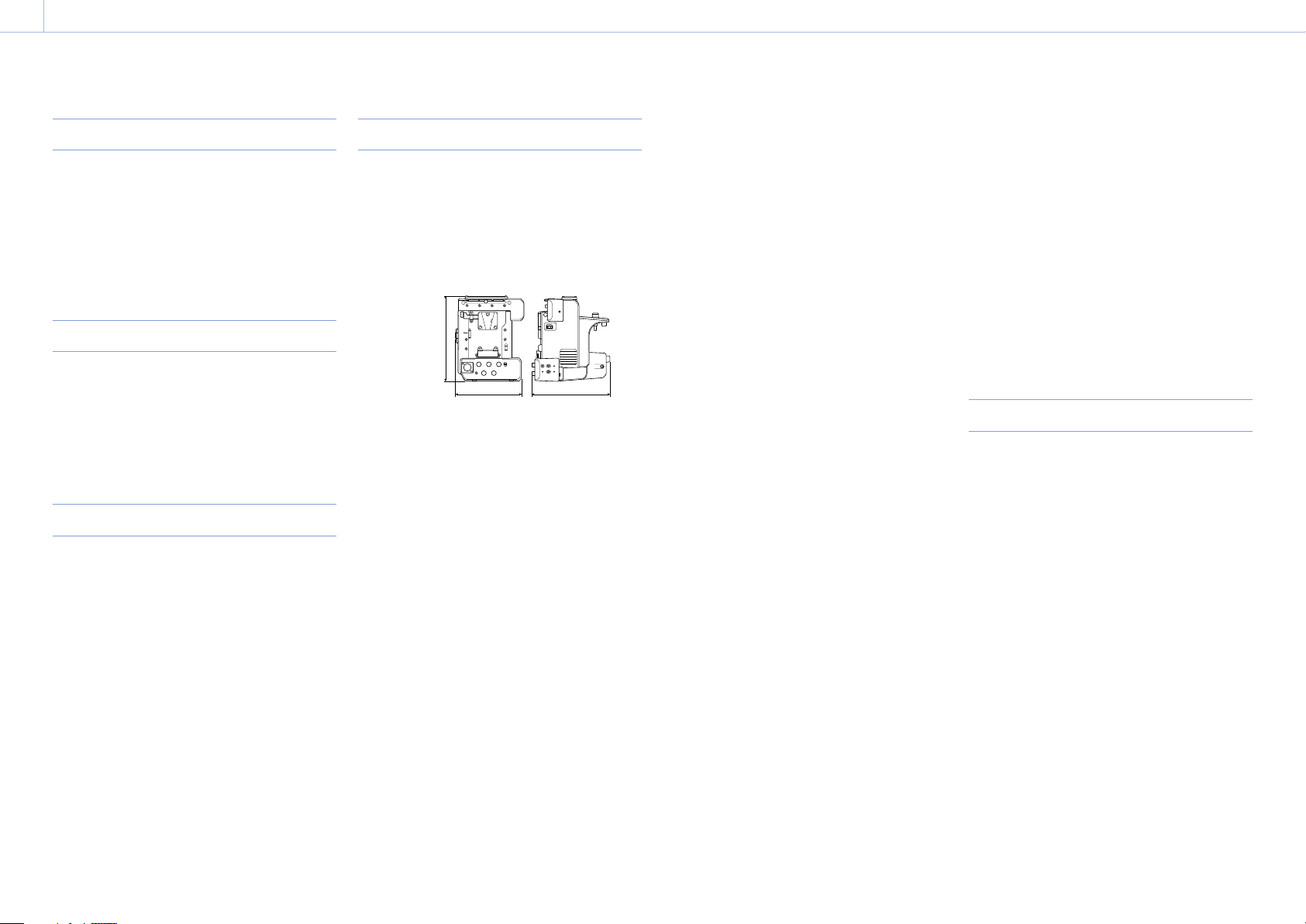
8. Appendix
00051
Specifications
Shoulder Plate
Mass Plate: Approx. 670g (1lb8oz)
Rods (each): Approx. 44g (1.6oz)
Dimensions
Approx. 129.8 × 57.8 × 250mm
1
(5
/8 × 23/8 × 97/8in)
(width / height / depth)
Top Plate
Mass Approx. 335g (12oz)
Dimensions
Approx. 106.5 × 74 × 221.4mm
1
(4
/4 × 3 × 83/4in)
(width / height / depth)
Viewfinder
Mass Approx. 644g (1lb7oz)
Dimensions
Approx. 242 × 87 × 215mm
5
(9
/8 × 31/2 × 81/2in)
(width / height / depth)
Extension Unit
General
Mass Approx. 1kg (2lb 3oz)
Dimensions
(Unit: mm (inch), excluding
protrusions)
177.3 (7)
136.5 (5
1) The values for dimensions are approximate.
Power requirements
12V DC (11V to 17.0V)
Power consumption
Approx. 45W (PXW-FS7 connected,
RAW output mode, using WRR,
wireless LAN video monitoring,
proxy recording. 23W consumed
by extension unit itself)
Approx. 72W (PXW-FS7 connected,
RAW output mode, using WRR,
wireless LAN video monitoring,
proxy recording, 2.0A output from
DC OUT connector)
Operating temperature
0°C to 40°C (32°F to 104°F)
Storage temperature
–20°C to +60°C (–4°F to +140°F)
Continuous operating time
Approx. 120minutes (using BP-FL75,
camcorder set to RAW output)
Output format (RAW OUT)
4K RAW for HXR-IFR5
2K RAW for HXR-IFR5
1)
3
/8) 157.3 (6 1/4)
Output frame rate (RAW OUT)
4K: 4096×2160/59.94P, 50P, 29.97P,
23.98P, 25P
2K: 2048×1080/59.94P, 50P, 29.97P,
23.98P, 25P, 100P, 119.88P, 200P,
239.76P
ProRes recording format (PXW-FS7/PXW-FS7M2)
1920×1080/59.94i, 50i, 29.97P, 25P,
23.98P
ProRes 422 HQ
Apple ProRes 422 HQ 4:2:2, 10-bit,
VBR, 220Mbps max.
ProRes 422
Apple ProRes 422 4:2:2, 10-bit, VBR,
147Mbps max.
Input/outputs
Inputs
GENLOCK IN
BNC type, 1.0Vp-p, 75Ω, unbalanced
TC IN BNC type, 0.5V to 18Vp-p, 10kΩ
SDI IN BNC type
WRR D-Sub 15-pin
Analog CH1: –40dBu
Outputs
RAW OUT BNC type, 0.8Vp-p, unbalanced
HXR-IFR5 dedicated output
REF OUT BNC type, REF SYNC output 0.6Vp-p
±0.1Vp-p, 75Ω
TC OUT BNC type, 1.0Vp-p, 75Ω
SDI OUT BNC type, SDI IN pass-through output
(when network module is on)
Other
DC IN XLR type, 4-pin, male, 11V to 17V DC
DC OUT 4-pin round type, 10V to 12.5V DC,
2.0A maximum rated current
(total, including LIGHT connector)
REC Tally signal output and REC
Trigger signal input are supported
via the DC OUT connector.
LIGHT 2-pin, 12V DC (20W or lower)
DATA IN/OUT
10-pin round type (for handle adapter
connection)
USB connector
USB 2.0 compliant, type A, for wireless
LAN module or modem (2)
CAM connector
USB 2.0 compliant, Micro B type (for
camera control)
SD card slot
For SD card
[Note]
Only connect devices with current consumption of 2.0A or
lower to the DC OUT connector.
Supplied accessories
USB cable (1)
SDI BNC cable (1)
Dongle guard (2)
Dongle guard mounting plate (1)
Mounting plate screws (4)
Shoulder belt (1)
Joint plate (1)
Rod (2)
Cable clamp (2)
Hex screws (4)
Before Using This Unit (1)
Operating Instructions (CD-ROM) (1)
Warranty booklet (1)
Page 52

8. Appendix: Specifications
00052
Trademarks
Android and Google Chrome are trademarks or
registered trademarks of Google Inc.
Microsoft and Windows are registered
trademarks of Microsoft Corporation in the
United States and/or other countries.
Apple, Macintosh, Safari, and iPhone, and logos
are trademarks or registered trademarks of
Apple Inc. in the United States and/or other
countries.
Wi-Fi® is a registered trademark of the Wi-Fi
Alliance®.
WPA™, WPA2™, and Wi-Fi Protected Setup™ are
trademarks of the Wi-Fi Alliance®.
All other company and product names are
trademarks or registered trademarks of the
respective owners. Trademarked items are not
indicated by ™ or ® symbols in this document.
 Loading...