

Page 1
50 PIN IF AND DIGITAL EXTENDER
CBK-CE01
!警告
このマニュアルは,サービス専用です。
お客様が,このマニュアルに記載された設置や保守,点検,修理などを行うと感電や火災,人身
事故につながることがあります。
危険をさけるため,サービストレーニングを受けた技術者のみご使用ください。
設置や保守,点検,修理などを行う前に,PMW-350/320/EX330 に付属している下記マニュア
ルの「安全のために」を必ずお読みください。
.取扱説明書
! WARNING
This manual is intended for qualifi ed service personnel only.
To reduce the risk of electric shock, fi re or injury, do not perform any servicing other than
that contained in the operating instructions unless you are qualifi ed to do so. Refer all
servicing to qualifi ed service personnel.
! WARNUNG
Die Anleitung ist nur für qualifi ziertes Fachpersonal bestimmt.
Alle Wartungsarbeiten dürfen nur von qualifi ziertem Fachpersonal ausgeführt werden.
Um die Gefahr eines elektrischen Schlages, Feuergefahr und Verletzungen zu
vermeiden, sind bei Wartungsarbeiten strikt die Angaben in der Anleitung zu befolgen.
Andere als die angegeben Wartungsarbeiten dürfen nur von Personen ausgeführt
werden, die eine spezielle Befähigung dazu besitzen.
! AVERTISSEMENT
Ce manual est destiné uniquement aux personnes compétentes en charge de l’
entretien. Afi n de réduire les risques de décharge électrique, d’incendie ou de blessure
n’effectuer que les réparations indiquées dans le mode d’emploi à moins d’être qualifi é
pour en effectuer d’autres. Pour toute réparation faire appel à une personne compétente
uniquement.
INSTALLATION MANUAL
1st Edition (Revised 1)
Page 2

Page 3

Section 1
Installation
Purpose of this manual
This manual is the installation manual of the 50 PIN IF AND DIGITAL EXTENDER
CBK-CE01.
This manual is intended for use by trained system and service engineers, and describes
the information on installing the CBK-CE01.
Related manuals
Besides this installation manual, the following manual is prepared for CBK-CE01.
. PMW-350/320/EX330 Operating Instructions (Supplied with PMW-350/320/EX330)
This manual describes the application and operation of PMW-350/320/EX330.
. PMW-350/320/EX330 Maintenance Manual (Available upon request)
This manual describes the detailed maintenance information and repair information
of the PMW-350/320/EX330 that are required for parts-level service.
For obtaining, contact your local Sony Sales Offi ce/Service Center.
CBK-CE01
1-1 (E)
Page 4

1-1. General Information for Installation
Parts confi guration
The 50 PIN IF AND DIGITAL EXTENDER CBK-CE01 consists of the following
parts.
. RX-119A board assembly
. Radiation sheet
. 50P CN assembly
. 50P cover assembly
. Tapes (two)
. Attaching screws
B2 x 5 (four)
PSW2 x 5 (four)
. Installation Manual
. Installation Guide
On installation
Install the CBK-CE01 and check that the CBK-CE01 is properly installed according to
the installation and check procedure described in section 1-2 and 1-3.
Standard Torque for Screws
When tightening a screw, be sure to use the specifi ed torque driver and tightening
torque.
Fixtures
. Bit for torque driver (for M2)
M2 (+) screw: 19 x 10
. Bit for torque driver (for M3)
M3 (+) screw: 80 x 10
_2
?0.01 N.m (1.9 ?0.1 kgf.cm)
_2
?0.01 N.m (8.0 ?0.1 kgf.cm)
1-2 (E)
CBK-CE01
Page 5
1-2. Installation Procedure
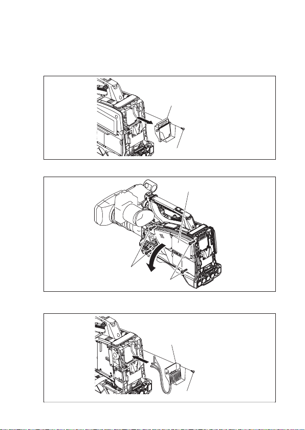
1. Remove the four screws to detach the 50P cover assembly.
50P cover assembly
M2
2. Loosen the four screws with stopper to detach the inside panel assembly.
Inside panel assembly
Screws with stopper
Screws with stopper
3. Install the 50P CN assembly with the supplied four screws (B2 x 5).
50P CN assembly
CBK-CE01
B2 x 5
1-3 (E)
Page 6
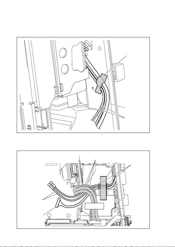
4. Clamp the two coaxial cables and the harness of the 50P CN assembly to the frame
of the main unit with tape.
Tap e
Harness
Coaxial
cables
5. Pass the two coaxial cables and the harness of the 50P CN assembly under the
harness (gray) and then through the space under the claws and clamp them with tape.
Coaxial cables
Harness
1-4 (E)
Harness (gray)
Tap e
Claws
CBK-CE01
Page 7
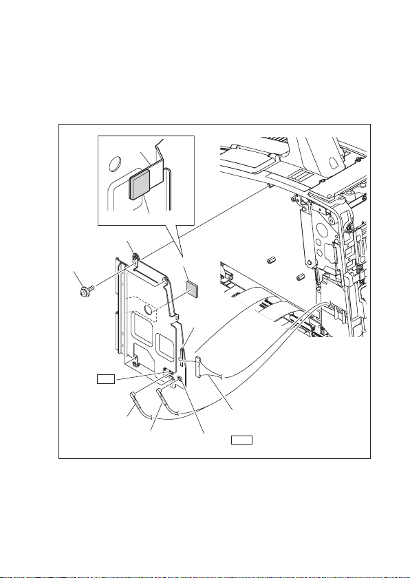
6. Remove the protection sheets on both sides of the radiation sheet and stick it on
the heatsink of the RX-119A board.
7. Install the RX-119A board with four screws (PSW2 x 5) and connect the coaxial
cable (black), coaxial cable (white), and harness to the connectors CN501 [BLK],
CN502 [WHT], and CN103 respectively on the RX-119A board.
Heatsink
Radiation sheet
RX-119A board
PSW2 x 5
CN501 BLK
Coaxial cable (black)
Coaxial cable (white)
Radiation sheet
CN103
Harness
CN502 WHT
8. Install the inside panel assembly by reversing the steps of removal.
CBK-CE01
1-5 (E)
Page 8
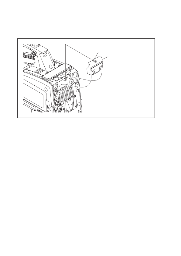
9. Install the 50P cover assembly supplied with the CBK-CE01 with the screw with
stopper.
Screw with stopper
50P cover assembly
(Supplied with the
CBK-CE01)
1-6 (E)
CBK-CE01
Page 9

1-3. Check after Installation
Check procedure
1. Turn on the power of the main unit.
2. Display the “MAINTENANCE” menu on the viewfi nder referring the operating
instructions supplied with the main unit.
3. Confi rm that “CBK-CE01:Vx.xxx” is displayed on the “Version” window.
CBK-CE01
1-7 (E)
Page 10

CBK-CE01 (SY) J,E
4-259-869-02
Sony Corporation
Printed in Japan
2011. 3 08
©2010
 Loading...