

Sony F65, CBK-65EL Operation Manual

DIGITAL MOTION PICTURE CAMERA
F65
F65 UPGRADE KIT
CBK-65EL
OPERATION MANUAL [English]
2nd Edition
Before operating the unit, please read this manual thoroughly
and retain it for future reference.
WARNING
To reduce the risk of fire or electric shock,
do not expose this apparatus to rain or
moisture.
To avoid electrical shock, do not open the
cabinet. Refer servicing to qualified
personnel only.
Egenskaper för intern lasermodul
Våglängd : 850 nm
Strålningens varaktighet : Pulsmodulation
Lasereffekt : 4 mW/kanal (max)
Standard : IEC60825-1 (2007)
Egenskaper for innvendig lasermodul
Bølgelengde : 850 nm
Strålingsvarighet : Pulsmodulasjon
Utgangseffekt for laser : 4 mW / kanal (maks.)
Standard : IEC60825-1 (2007)
Caution
The use of optical instruments with this product will increase
eye hazard.
Caution
Use of controls or adjustments or performance of procedures
other than those specified herein may result in hazardous
radiation exposure. Do not open the outer case and
disassemble or otherwise modify.
This Digital Motion Picture Camera is classified as a CLASS 1
LASER PRODUCT.
Tämä Digital Motion Picture Camera on luokiteltu 1. LUOKAN
LASERTUOTTEEKSI.
Den här Digital Motion Picture Camera klassificeras som en
LASERPRODUKT AV KLASS 1.
VAROITUS!
LAITTEEN KÄYTTÄMINEN MUULLA KUIN TÄSSÄ
KÄYTTÖOHJEESSA MAINITULLA TAVALLA SAATTAA
ALTISTAA KÄYTTÄJÄN TURVALLISUUSLUOKAN 1
YLITTÄVÄLLE NÄKYMÄTTÖMÄLLE LASERSÄTEILYLLE.
For the customers in the U.S.A.
This equipment has been tested and found to comply with the
limits for a Class A digital device, pursuant to Part 15 of the
FCC Rules. These limits are designed to provide reasonable
protection against harmful interference when the equipment is
operated in a commercial environment. This equipment
generates, uses, and can radiate radio frequency energy and,
if not installed and used in accordance with the instruction
manual, may cause harmful interference to radio
communications. Operation of this equipment in a residential
area is likely to cause harmful interference in which case the
user will be required to correct the interference at his own
expense.
You are cautioned that any changes or modifications not
expressly approved in this manual could void your authority to
operate this equipment.
All interface cables used to connect peripherals must be
shielded in order to comply with the limits for a digital device
pursuant to Subpart B of Part 15 of FCC Rules.
This device complies with Part 15 of the FCC Rules. Operation
is subject to the following two conditions: (1) this device may
not cause harmful interference, and (2) this device must
accept any interference received, including interference that
may cause undesired operation.
VARNING
OM APPARATEN ANVÄNDS PÅ ANNAT SÄTT ÄN I DENNA
BRUKSANVISNING SPECIFICERATS, KAN ANVÄNDAREN
UTSÄTTAS FÖR OSYNLIG LASERSTRÅLNING, SOM
ÖVERSKRIDER GRÄNSEN FÖR LASERKLASS 1.
Internal Laser Module Properties
Wavelength : 850 nm
Emission duration : Pulse Modulation
Laser output power : 4 mW/channel (max)
Standard : IEC60825-1 (2007)
Egenskaber for internt lasermodul
Bølgelængde : 850 nm
Strålingsvarighed : Pulsmodulering
Afgivet lasereffekt : 4 mW/kanal (maks.)
Standard : IEC60825-1 (2007)
2
For the customers in Canada
This Class A digital apparatus complies with Canadian ICES-
003.
For the customers in Europe
This product with the CE marking complies with the EMC
Directive issued by the Commission of the European
Community.
Compliance with this directive implies conformity to the
following European standards:
• EN55103-1: Electromagnetic Interference(Emission)
• EN55103-2: Electromagnetic Susceptibility(Immunity)
This product is intended for use in the following
Electromagnetic Environments: E1 (residential), E2
(commercial and light industrial), E3 (urban outdoors), E4
(controlled EMC environment, ex. TV studio).
This product has been manufactured by or on behalf of Sony
Corporation, 1-7-1 Konan Minato-ku Tokyo, 108-0075 Japan.
Inquiries related to product compliance based on European
Union legislation shall be addressed to the authorized
representative, Sony Deutschland GmbH, Hedelfinger
Strasse 61, 70327 Stuttgart, Germany. For any service or
guarantee matters, please refer to the addresses provided in
the separate service or guarantee documents.
AVERTISSEMENT
Afin de réduire les risques d’incendie ou
d’électrocution, ne pas exposer cet
appareil à la pluie ou à l’humidité.
For the State of California, USA only
Perchlorate Material - special handling may apply, See
www.dtsc.ca.gov/hazardouswaste/perchlorate
Perchlorate Material : Lithium battery contains perchlorate.
For the customers in Taiwan only
Afin d’écarter tout risque d’électrocution,
garder le coffret fermé. Ne confier
l’entretien de l’appareil qu’à un personnel
qualifié.
Digital Motion Picture Camera est classée comme PRODUIT
LASER DE CLASSE 1.
Propriétés du module laser interne
Longueur d’onde : 850 nm
Durée d’émission : Modulation d’impulsion
Puissance du laser : 4 mW/canal (max)
Norme : IEC60825-1 (2007)
Pour les clients au Canada
Cet appareil numérique de la classe A est conforme à la
norme NMB-003 du Canada.
Pour les clients en Europe
Ce produit portant la marque CE est conforme à la Directive
sur la compatibilité électromagnétique (EMC) émise par la
Commission de la Communauté européenne.
La conformité à cette directive implique la conformité aux
normes européennes suivantes :
• EN55103-1 : Interférences électromagnétiques (émission)
• EN55103-2 : Sensibilité électromagnétique (immunité)
Ce produit est prévu pour être utilisé dans les environnements
électromagnétiques suivants : E1 (résidentiel), E2
(commercial et industrie légère), E3 (urbain extérieur) et E4
(environnement EMC contrôlé, ex. studio de télévision).
Ce produit a été fabriqué par ou pour le compte de Sony
Corporation, 1-7-1 Konan Minato-ku Tokyo, 108-0075 Japon.
Toutes les questions relatives à la conformité des produits
basées sur la législation européenne doivent être adressées à
son représentant, Sony Deutschland GmbH, Hedelfinger
Strasse 61, 70327 Stuttgart, Allemagne.
Pour toute question relative au Service Après-Vente ou à la
Garantie, merci de bien vouloir vous référer aux coordonnées
qui vous sont communiquées dans les documents « Service
(SAV) » ou Garantie.
3
WARNUNG
Um die Gefahr von Bränden oder
elektrischen Schlägen zu verringern, darf
dieses Gerät nicht Regen oder Feuchtigkeit
ausgesetzt werden.
Um einen elektrischen Schlag zu
vermeiden, darf das Gehäuse nicht
geöffnet werden. Überlassen Sie
Wartungsarbeiten stets nur qualifiziertem
Fachpersonal.
Dieser Digital Motion Picture Camera ist als
LASERPRODUKT DER KLASSE 1 eingestuft.
Eigenschaften des internen Lasermoduls
Wellenlänge : 850 nm
Emissionsdauer : Pulsmodulation
Laser-Ausgangsleistung : 4 mW/Kanal (max.)
Standard : IEC60825-1 (2007)
Für Kunden in Europa
Dieses Produkt besitzt die CE-Kennzeichnung und erfüllt die
EMV-Richtlinie der EG-Kommission.
Angewandte Normen:
• EN55103-1: Elektromagnetische Verträglichkeit
(Störaussendung)
• EN55103-2: Elektromagnetische Verträglichkeit
(Störfestigkeit)
Für die folgenden elektromagnetischen Umgebungen: E1
(Wohnbereich), E2 (kommerzieller und in beschränktem
Maße industrieller Bereich), E3 (Stadtbereich im Freien) und
E4 (kontrollierter EMV-Bereich, z.B. Fernsehstudio).
Dieses Produkt wurde von oder für Sony Corporation, 1-7-1
Konan Minato-ku Tokio, 108-0075 Japan hergestellt.
Bei Fragen zur Produktkonformität auf Grundlage der
Gesetzgebung der Europäischen Union kontaktieren Sie bitte
den Bevollmächtigten Sony Deutschland GmbH, Hedelfinger
Strasse 61, 70327 Stuttgart, Deutschland. Für Kundendienst
oder Garantieangelegenheiten wenden Sie sich bitte an die in
den Kundendienst- oder Garantiedokumenten genannten
Adressen.
4

Table of Contents
Chapter 1 Overview
1-1 Features ...........................................................................7
1-2 Example of System Configuration ..............................10
1-2-1 SR-R4 Docking System .................................................11
1-3 Locations and Functions of Parts ...............................12
Chapter 2 Installation and Preparations
2-1 Mounting the SR-R4 .....................................................17
2-2 Attaching a Filter ..........................................................18
2-3 Attaching a Lens ...........................................................19
2-4 Attaching a Viewfinder .................................................21
2-5 Mounting the Camera on a Tripod ..............................22
2-6 Mounting the CBK-WA01 .............................................22
2-7 Preparing the Power Supply ........................................23
2-8 Setting the Date and Time ............................................24
Chapter 3 Basic Adjustments and Settings
3-1 Basic Operation of the Camera ...................................25
3-2 Camera Settings ...........................................................26
3-3 Basic Settings using the Subdisplay ..........................26
3-3-1 Basic Operation of the Subdisplay .................................26
3-3-2 Setting the Video Format ...............................................27
3-3-3 Setting the Shutter Value ...............................................28
3-3-4 Selecting an ND Filter ....................................................30
3-3-5 Setting the Sensitivity (EI Value) (Cine Mode) .............30
3-3-6 Setting the Color Temperature .......................................30
3-3-7 Setting the SDI OUT2 Output Color Space ...................31
3-3-8 Setting the SDI OUT2 Output LUT ...............................31
3-3-9 Selecting the Fan Operating Mode .................................32
3-3-10 Checking the Voltages .................................................32
3-3-11 Checking the Remaining Media ...................................33
3-3-12 Checking the File Name ...............................................33
3-3-13 Checking the Time Code ..............................................33
3-3-14 Assigning Functions to the ASSIGN Buttons ..............33
3-3-15 Adjusting the Subdisplay Brightness ...........................34
Table of Contents
5

3-3-16 Checking the Self-Diagnostic Results .........................35
3-4 VF Menu Basic Operation ........................................... 35
3-5 Setting the Shooting Mode ......................................... 37
3-6 Setting the Output Signal ............................................ 38
3-6-1 Adjusting the Output Signal Image ...............................38
3-6-2 Selecting the Viewfinder Output Signal ........................ 39
3-7 Viewing and Setting the Viewfinder Display ............. 39
3-7-1 Viewing the Basic Status Display .................................. 39
3-7-2 Setting the Marker Display ............................................40
3-7-3 Setting the Voltage Warning Values .............................41
3-7-4 Magnifying the Image Display ......................................41
3-7-5 Monitoring High Key Blown-out Highlights and Low Key
Clipped Blacks ............................................................... 42
3-8 Restoring the factory default settings ....................... 42
Chapter 4 Menu Configuration and Detailed Settings
4-1 Subdisplay Menu List .................................................. 43
4-2 VF Menu List ................................................................. 46
4-2-1 Camera Menu .................................................................47
4-2-2 VF/SDI Menu ................................................................51
4-2-3 Display Info Menu .........................................................54
4-2-4 Config Menu ..................................................................56
4-2-5 File Menu .......................................................................58
4-2-6 Network Menu ...............................................................60
4-2-7 Diagnosis Menu .............................................................61
Appendix
Table of Contents
6
Metadata .............................................................................. 62
RDD 18 format metadata set .................................................... 62
Non-realtime metadata .............................................................64
Warning/Error Messages .................................................... 66
Precautions ......................................................................... 68
Cleaning the Recorder Connector ..................................... 69
About “Memory Stick Duo” ................................................ 69
Specifications ...................................................................... 71
Connector Pin Assignments .............................................. 74
Menu Operation using a Web Browser ............................. 77
Operation using a Tablet Device ....................................... 77
Color Space According to the COLOR SPACE
Settings ......................................................................... 79
Notice Concerning Software Governed by the GNU
GPL/LGPL ..................................................................... 80

Chapter 1 Overview
Overview
1-1 Features
The F65 is a digital motion picture camera equipped with
a Super 35-mm type CMOS sensor array with a total of 20
Megapixels.
The camera is incorporated with newly developed imagers
and a digital signal-processing LSI that yield images of a
high quality for cinematic, commercial, and dramatic
production applications. The camera also supports the
features of a “production camera” up to details in its shape,
button and indicator layout, and materials of the parts.
Note
F65 software or SR-R4/SRK-CP1 software, V3.00 or later,
is required in order to use the various functions described
in this manual.
The description in this manual assumes an F65 camera
fitted with the CBK-65EL upgrade kit.
Superior picture quality and high
performance
Chapter
The camera supports the following formats.
F65RAW mode: 23.98p, 24p, 25p, 29.97p, 50p, 59.94p,
S47.95 (Select FPS), S48 (Select FPS), S59.94p (Select
FPS), S60p (Select FPS)
F65RAW-HFR mode: S119.88p (Select FPS), S120p
(Select FPS)
HD mode: 23.98p, 24p, 25p, 29.97p, 50p, 59.94p,
S59.94p (Select FPS), S60p (Select FPS)
Imaging characteristics with wide color space
Sony’s unique technology color filters allow the camera to
capture images with natural-looking color reproduction
close to those of the actual scene.
S-LOG gamma and 709(800%) gamma for
monitors
The camera is equipped with S-LOG gamma for checking
the entire dynamic range of the image, and 709(800%)
gamma for general monitoring.
Mechanical rotary shutter
The camera is equipped with a mechanical rotary shutter
that eliminates the rolling shutter effect common to
conventional CMOS image sensors.
1
Super 35-mm type CMOS and PL mount
With the F65’s Super 35-mm-type CMOS imagers and PL
mount, most movie lenses designed for conventional 35mm film cameras can be mounted without a converter.
Wide latitude and high-quality pictures
With its newly developed imagers, and unique 16-bit
digital LSI, the camera achieves wide latitude and highgrade picture quality with minimal noise.
RAW image output
Outputs RAW image data, without camera signal
processing or non-linear gamma processing, for increased
convenience during post-production.
Multiple frame formats
The camera supports 3840/4096-pixel wide images for
high-end content creation, including commercial and
broadcasting program production as well as movie
making.
HD shooting
When used with the SR-R4 recorder, the camera can also
shoot images in HD mode, in addition to RAW mode.
SR-R4 version 1.4 or later is required to record in HD.
HFR (high frame rate) mode
Supports recording at 120 frames per second. Frame rates
from 1 to 120 fps can be selected using Select FPS.
In HFR mode, the ND filter is set to Clear, and the
mechanical rotary shutter cannot be used.
In addition, only when the frame rate is set to 120 fps, two
cameras can be genlocked so that the phase of the images
obtained are synchronized.
2-system independent SDI outputs
Selectable, independent signal output on SDI1 and SDI2.
• A signal with a varied “look” (tone and color space)
based on CDL or 3D LUT can be selected for output on
SDI1.
Features
7

• A video assist monitor image using Hi/Lo Key, MAG, or
other effects can be selected for output on SDI2, in
addition to the standard LUT.
Note
The SDI1 system supports “Graded ACES” and “Look
Chapter 1 Overview
Profile” settings that perform color conversion using a
built-in 3D LUT. The F65 employs a 3D LUT with
17×17×17 lattice to obtain a contour line signal for areas
of smoothly varying luminous intensity.
The recording signal is not affected, allowing the
processing to be improved using a color grading tool that
performs color conversion employing a higher-degree 3D
lattice grid.
DVF-EL100 viewfinder connection
Connects to the DVF-EL100 OLED color viewfinder
(option) that displays a high-resolution, accurate color
reproduction image.
1) The DVF-L350/L700 viewfinder is not supported.
1)
Design and shape
New compact design
For a high level of mobility in consideration of various
shooting situations, such as inside a car, the camera is
housed in as compact a body as possible. In addition,
buttons and indicators are laid out to provide a familiar and
intuitive user interface to users of conventional cinema
film cameras.
Dockable system for the SR-R4 Portable Memory
Recorder
A dockable interface system for docking with the SR-R4 is
employed for versatility under shooting conditions and onsite demands.
Compatible with film-camera accessories
The F65 is designed to be compatible with a variety of
film-camera accessories, giving users a broad array of
choices. These include ARRIFLEX-made bridge plates,
matte boxes, follow focus units, lens focus/zoom/iris servo
control units, and more. These film-camera accessories
can be attached to the F65 without modification, enabling
users who principally work with film to fully utilize their
existing assets.
The F65 is equipped with one 12 V DC and connector one
24 V DC
connected to the camera.
1) To supply accessories with 24 V DC power, the camera must have both
Assignable buttons
The F65 is equipped with assignable buttons on the side of
the camera head.
1)
output connector to supply power to accessories
12 V DC and 24 V DC supplies, and the CAM POWER switch must be
turned ON.
The operator can assign frequently used functions, such as
magnifying the image in the viewfinder, to assignable
buttons to call these functions rapidly when working in the
field.
Operational versatility
Cine mode
This mode records video without processing, on the
presumption color grading is performed in postproduction, while applying basic color grading to the VF/
SDI outputs.
In Cine mode, the camera can be operated just like a
conventional film camera.
Custom mode
This mode allows you to adjust the black/white level and
the gain of the main signal when creating images on
location.
This mode also supports camera control by connecting a
remote control unit (RM).
Shutter control
The shutter speed is adjustable in terms of shutter angle.
You can also switch between a mechanical rotary shutter
and an electronic shutter.
Sensitivity adjustment function
In Cine mode, the F65 employs an EI sensitivity indicator
for shooting using a light meter, just as for film cameras, to
enable overexposure/underexposure processing in postproduction.
ASC CDL
American Society of Cinematographers Color Decision
List (ASC CDL) is a format for the exchange of basic color
grading information, recommended by ASC. The CDL
parameters can be specified by importing a CDL file or by
adjusting using the F65Remote Look Plus remote control
application. The adjustments made are not reflected in the
master video signal, but are saved as metadata in the SRR4 recorder. When recording, the video can be monitored
on the VF/SDI outputs by applying the values in metadata
to the recorded material.
Other features
USB host connectors
The camera is equipped with USB connectors (host) for
connection with an optional Wi-Fi adapter (CBK-WA01)
to enable wireless camera operation from a tablet or other
Wi-Fi capable device.
8
Features

Anamorphic format support
Normal VF/SDI video, without distortion, is output when
using a 2x anamorphic lens.
Supports various setup methods
The F65 can be configured from a variety of devices. The
basic configuration is performed on the camera’s
subdisplay. However, detailed settings can be performed
from the menu (VF Menu) displayed in the viewfinder or
on a monitor connected to the SDI OUT connector. You
can also make detailed settings by displaying the menu in
a web browser or on a tablet device, such as an iPad.
1) iPad is a trademark of Apple Inc.
2) The items displayed in the menu that can be configured using a web
browser or a tablet device may vary. For details, see “4-2 VF Menu List”
(page 46).
1,2)
Chapter 1 Overview
Features
9
1-2 Example of System Configuration
The diagram below shows a system configuration example
for use of this camera.
Chapter 1 Overview
This manual assumes the use of an optional Sony HD
Electronic Viewfinder.
Viewfinder
Product Model name
HD Electronic Viewfinder HDVF-C30WR, HDVF-C35W, HDVF-20A, HDVF-200, DVF-EL100
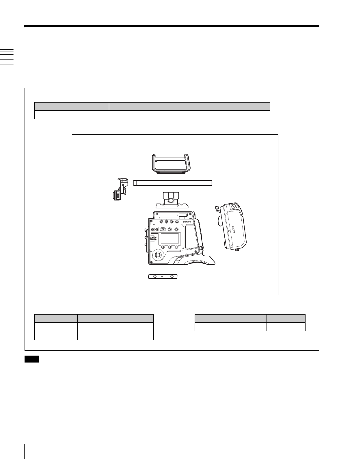
F65 Product Configuration
Viewfinder mounting plate
For more information about the fittings, connections, or
use of additional equipment and accessories, see “Chapter
2 Installation and Preparations” (page 17) as well as the
operation manuals for the connected equipment.
Center handle
19mm DIA carbon rod
Rod mounting plate
Riser plate
Products for tripod mounting
Product Model name
Bridge Plate BP-8 (ARRIFLEX)
Shoulder Set S-4 (ARRIFLEX)
Note
If attaching and using products, such as a shoulder set,
from other manufacturers, check beforehand that the
product can be fitted correctly to the camera.
SR-R4
Video recorder
Product Model name
Portable Memory Recorder SR-R4
Example of System Configuration
10
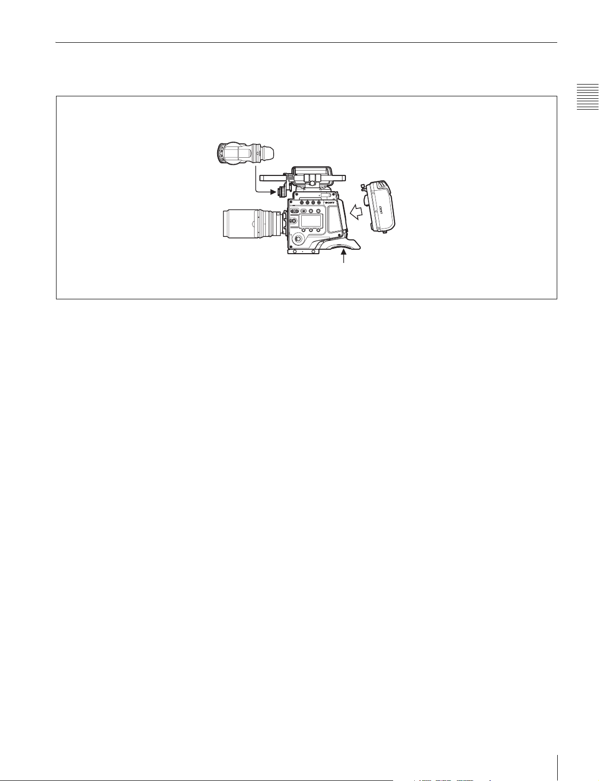
1-2-1 SR-R4 Docking System
An SR-R4 recorder can be docked on the rear of the camera head.
The SR-R4 power source is supplied via the camera’s DC IN connector.
HDVF-C30WR or DVF-EL100
12 V DC power
Chapter 1 Overview
SR-R4
Example of System Configuration
11
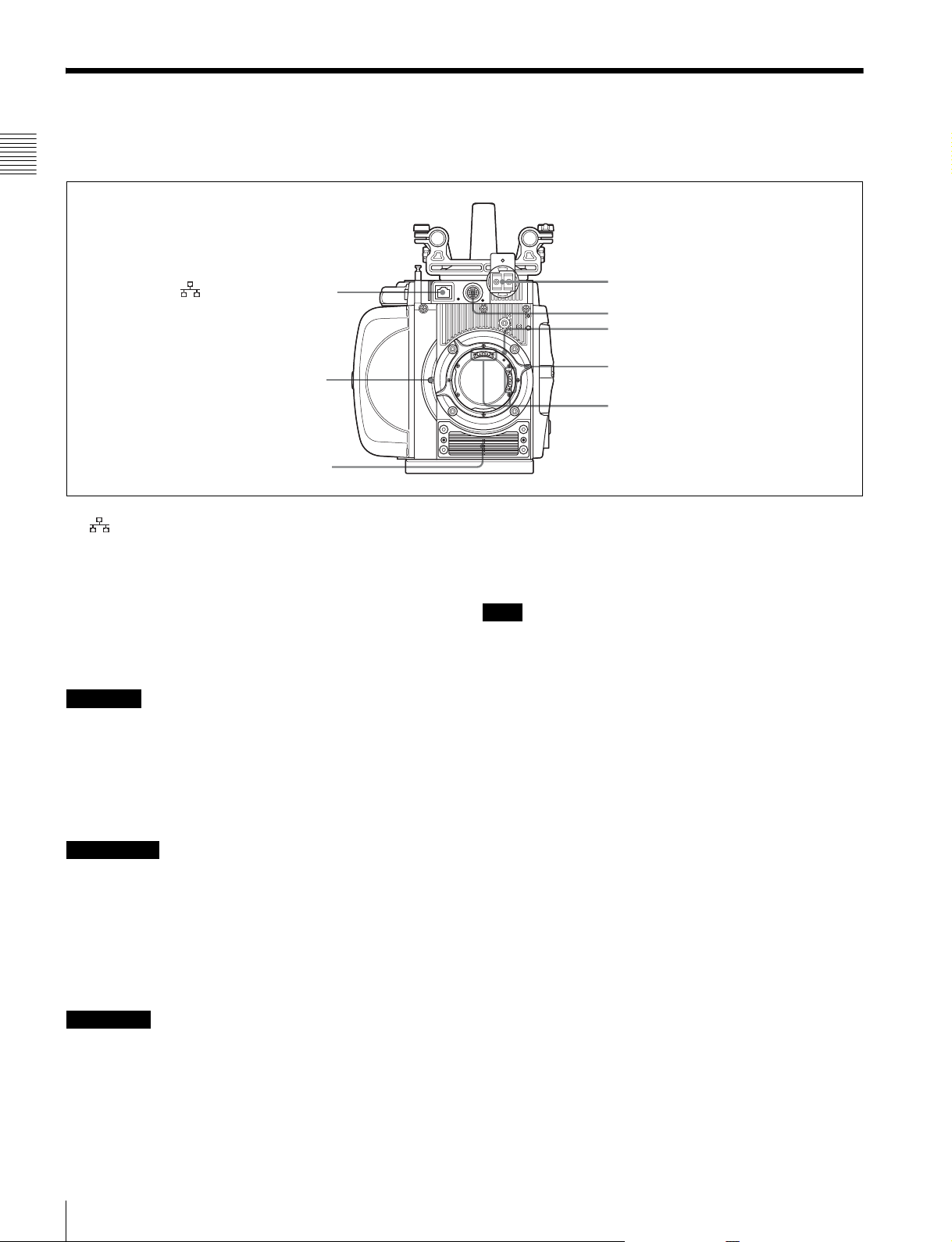
1-3 Locations and Functions of Parts
Front panel
Chapter 1 Overview
a (Network) connector
Shutter emergency open
screw (page 68)
b Ventilation holes (intake)
a (Network) connector (RJ-45 type, 10BASE-T/
100BASE-TX)
Connects to a network cable when configuring the camera
from a web browser on a computer.
For a network cable connection, the IP address must be
configured in the Network menu in the VF menu.
For details, see “4-2-6 Network Menu” (page 60).
CAUTION
• For safety, do not connect the connector for peripheral
device wiring that might have excessive voltage to this
port. Follow the instructions for this port.
• When you connect the network cable of the unit to
peripheral device, use a shielded-type cable to prevent
malfunction due to radiation noise.
c Viewfinder shoe
d VF connector
Lens mount
e Lens fixing lever
f Hot shoe
Kabel, um Fehlfunktionen aufgrund von Störungen zu
vermeiden.
b Ventilation holes (intake)
Note
Make sure that a gap of about 8 mm (
11
/32 inch) is
maintained in front of the ventilation holes for cooling.
c Viewfinder shoe
Attach an optional viewfinder.
For details, see “2-4 Attaching a Viewfinder” (page 21).
d VF (viewfinder) connector (20-pin)
Connects to the cable supplied with a viewfinder
(optional).
ATTENTION
• Par mesure de sécurité, ne raccordez pas le connecteur
pour le câblage de périphériques pouvant avoir une
tension excessive à ce port. Suivez les instructions pour
ce port.
• Lors de la connexion du câble réseau de l’appareil au
périphérique, utilisez un câble blindé afin d’empêcher
tout dysfonctionnement dû au bruit de rayonnement.
VORSICHT
• Aus Sicherheitsgründen nicht mit einem
Peripheriegerät-Anschluss verbinden, der zu starke
Spannung für diese Buchse haben könnte. Folgen Sie
den Anweisungen für diese Buchse.
• Verwenden Sie beim Anschließen des Netzwerkkabels
des Geräts an ein Peripheriegerät ein abgeschirmtes
Locations and Functions of Parts
12
e Lens fixing lever
When mounting a lens, turn the lever clockwise to secure
the lens. To remove the lens, turn the lever
counterclockwise.
If the lens fixing lever is difficult to operate due to the
shape of the lens or accessory being mounted, you can
remove the lever and attach it in a different orientation.
For details, see “2-3 Attaching a Lens” (page 19).
f Hot shoe
Supports the Cooke /i Intelligent Electronic Lens System
and can record lens information as metadata.
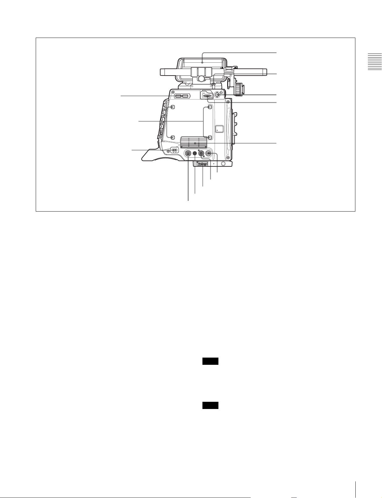
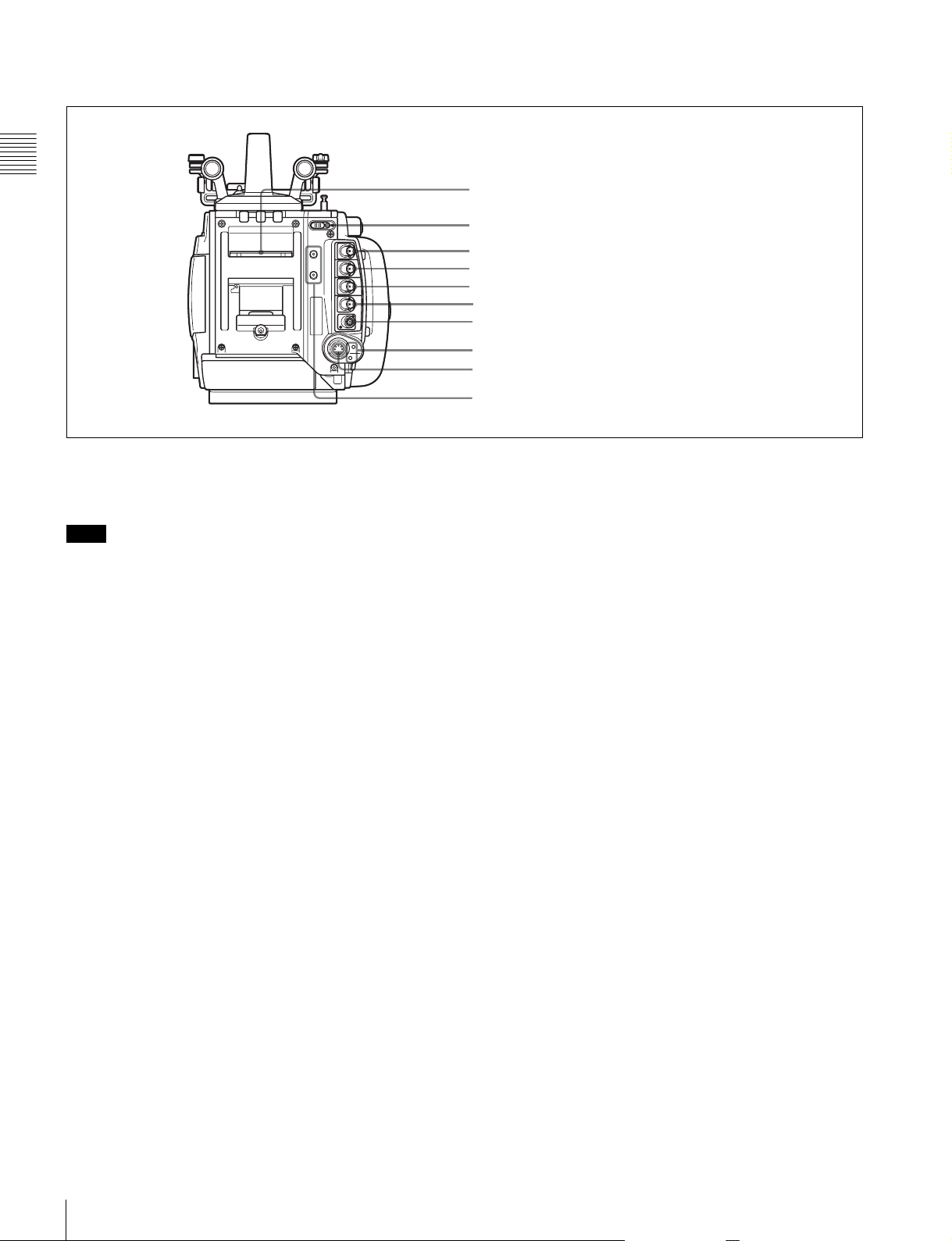
Left panel
i Handle
a USB connectors
b Accessory receptacles
c CAM POWER switch
a USB connectors
USB 2.0 standard connector. Connect a CBK-WA01 Wi-Fi
Adapter (optional) to enable communication with wireless
LAN devices.
j Measure hook/
focus reference mark
k SDI OUT2 connector
l VF connector (for DVF-EL100)
m Ventilation holes (exhaust)
h EXT. I/O connector
g LENS connector
f Wrench box
e DC OUT 24V 4A connector
d DC OUT 12V 4A connector
i Handle
The handle is attached to the top of the camera head at the
factory. It has two sizes of screw holes (
3
/8", 1/4") for
accessories on the upper side.
Chapter 1 Overview
b Accessory receptacles
For mounting accessories using M3 screws. The depth of
the screws is 5 mm (
7
/32 inch).
c CAM POWER switch
Turns the camera power supply ON/OFF.
d DC OUT 12V 4A (12 V DC supply output)
connector
Supplies 12 V DC power source to accessories, when the
CAM POWER switch is in the ON position.
e DC OUT 24V 4A (24 V DC supply output)
connector
Supplies 24 V DC power source to accessories when there
is a 24 V DC supply connected to the DC IN connector and
the CAM POWER switch is in the ON position.
f Wrench box
Stores a 3 mm (
1
/8 inch) wrench for attaching/detaching
the handle.
g LENS connector (12-pin)
Controls the aperture remotely with the connection of a
commercially-available iris servo unit.
j Measure hook/focus reference mark
Use as reference for focusing.
For actual measurement of the distance from a subject, you
can fix the end of a tape measure to the hook.
When shooting shallow depth-of-field images in high
resolution, it is recommended that you adjust the focus
using the camera or viewfinder magnification function.
k SDI OUT2 connector (BNC type)
Outputs the SDI2 Look (single link) signal.
l VF connector (26-pin, for DVF-EL100)
Connects to the DVF-EL100 viewfinder (option).
Note
To reduce OLED burn-in, use the DVF-EL100 switch to
turn VF DISPLAY (viewfinder display function) On/Off.
m Ventilation holes (exhaust)
Note
Connectors and other parts positioned near the exhaust
vents may become hot.
h EXT. I/O (external control) connector (5-pin)
It is not used in this version.
Locations and Functions of Parts
13
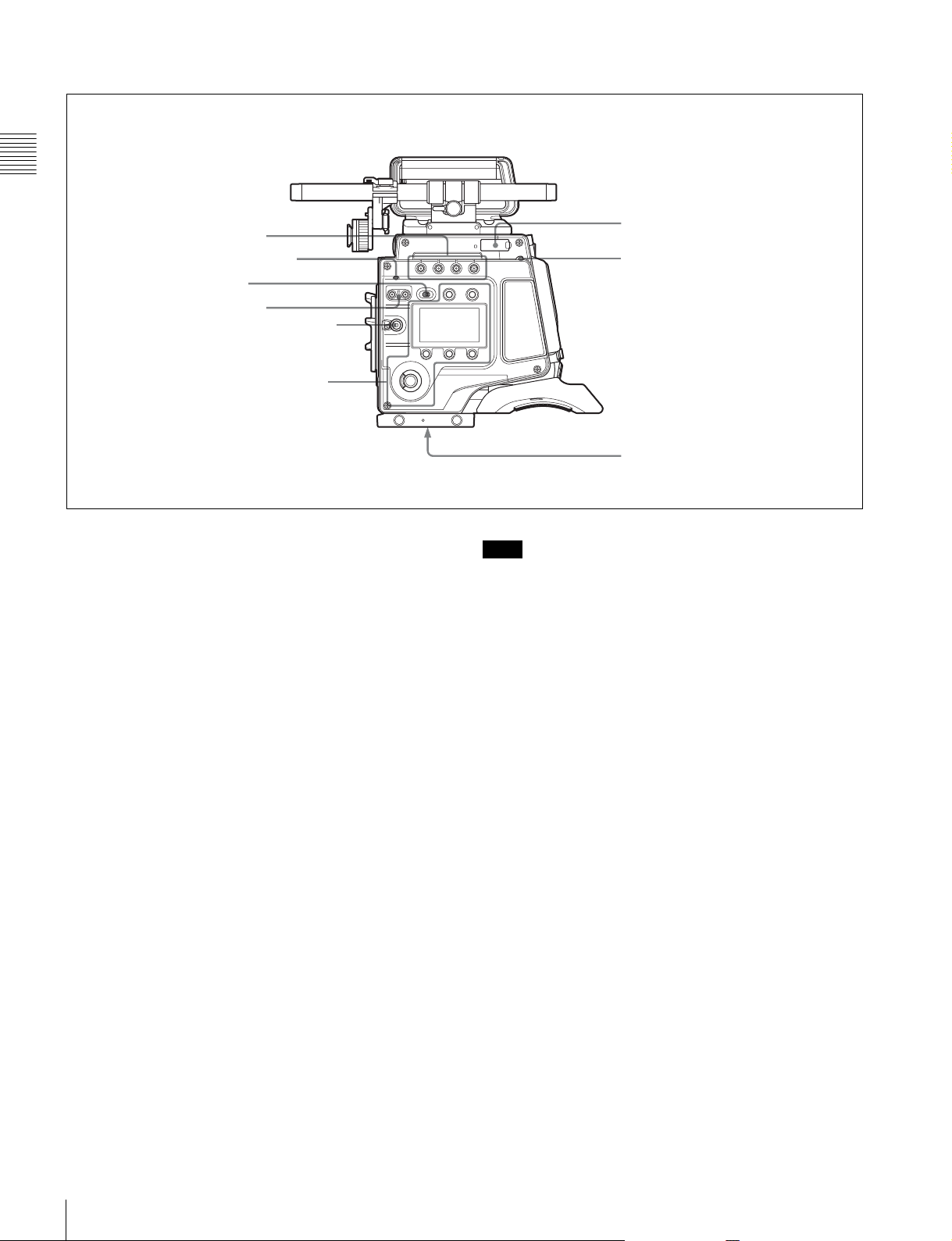
Right panel
Chapter 1 Overview
a ASSIGN buttons
b DIAGNOSIS indicator
c LOCK switch
d SHUTTER button
e REC button and LOCK switch
Display/menu operation block
a ASSIGN (assignable) buttons
You can assign various functions to these buttons, using
the subdisplay or the menu displayed in the viewfinder or
on a monitor.
ASSIGN button 1 is on the far left, and ASSIGN button 4
is on the far right.
For details, see “3-3-14 Assigning Functions to the
ASSIGN Buttons” (page 33).
b DIAGNOSIS indicator
Indicates the diagnostics status.
Lit green: Normal
Lit red: Error
Flashing red: Fatal error
Lit yellow: Not ready
If the red or flashing red indication continues, consult your
local Sony representative.
c LOCK switch
Locks operation of the side panel (excluding the REC and
PAGE buttons).
d SHUTTER button
Switches between the electronic shutter and the
mechanical rotary shutter.
Press the “M.” button for one second or longer to switch to
the mechanical rotary shutter, or press the “E.” button for
one second or longer to switch to the electronic shutter.
The button indicator for the selected shutter is lit. The
shutter indicator flashes when changing shutter.
f “Memory Stick”/
SD memory card section
g DOCK indicator
h Tripod receptacles (bottom)
Note
It takes about 20 to 40 seconds to change shutter.
e REC button and LOCK switch
The REC button starts/stops recording to the SR-R4
docked on the camera. The REC button indicator is lit
while recording. The indicator flashes as a warning if the
connected supply voltage drops.
When the LOCK switch is in the LOCK position, the REC
button cannot be operated.
The REC button cannot be operated during REC REVIEW,
PLAY, F.FWD, or REW mode on the SR-R4 to prevent
overwriting.
For details on warning indications, see “Warning/Error
Messages” (page 66).
f “Memory Stick”/SD memory card section
Slots for a “Memory Stick PRO Duo” and an SD memory
card are provided behind the rubber cap. The access lamp
turns red when a “Memory Stick PRO Duo” or an SD
memory card is inserted into a slot, and then turns off. It
flashes red when reading to or writing from a “Memory
Stick PRO Duo” or an SD memory card.
When the access lamp is flashing red, do not insert/remove
the “Memory Stick PRO Duo” or SD memory card, or turn
off the power.
g DOCK (docking) indicator
When an SR-R4 is docked, the light reception status of the
recorder connectors is displayed.
Green: Good
Locations and Functions of Parts
14
Yellow: Caution level
Sensitivity has decreased, but signal can be transferred
without error. Clean the recorder connector or replace
the connector optical module as soon as practicable.
Red: Light detection error
A light reception problem occurred, and signal cannot
be transferred correctly. Promptly clean the recorder
connector or replace the connector optical module.
Off: No signal
For details about cleaning the connectors, see “Cleaning
the Recorder Connector” (page 69). For information
about replacing the optical module, consult your local
Sony representative.
h Tripod receptacles (bottom)
Mounting point for a tripod using
3
/8" tripod screws.
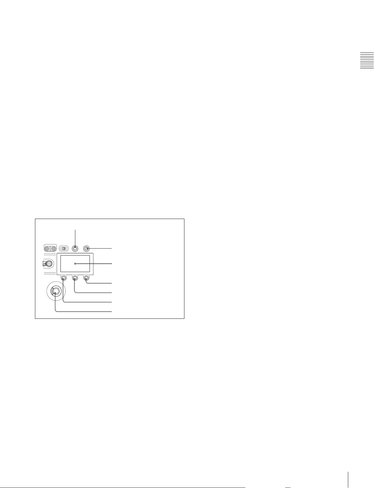
Display/menu operation block
Used to switch the monitor display between the subdisplay
and the viewfinder, and to operate the menus.
For details on menu operations, see “3-3-1 Basic
Operation of the Subdisplay” (page 26) and “3-4 VF Menu
Basic Operation” (page 35).
d SETTING button
Press and hold for 1 second or longer to enter Settings
Change mode to change camera settings using the
subdisplay.
e PAGE button
Displays the next page when the subdisplay is in Settings
Change mode.
f BACK button
Cancels changes and returns to the previous screen when
the subdisplay is in Settings Change mode or when
displaying the menu in the viewfinder or on a monitor.
Pressing the BACK button when the DVF adjustment
menu is displayed returns the display to the VF menu page
select screen.
g MENU SEL (selection)/ENTER dial
Turn the dial to select items and press to enter when the
subdisplay is in Settings Change mode or when displaying
the menu in the viewfinder or on a monitor.
Chapter 1 Overview
a VF DISPLAY button
b VF MENU button
c Subdisplay
d SETTING button
e PAGE button
f BACK button
g MENU SEL/ENTER dial
a VF DISPLAY (viewfinder display) button
Displays the status screen on the viewfinder and monitor.
For details about the information displayed, see “3-7
Viewing and Setting the Viewfinder Display” (page 39).
b VF MENU (viewfinder menu) button
Displays the menu screen on the viewfinder and monitor.
With the DVF-EL100 connected, press and hold this
button for two seconds or longer to display the Digital VF
Picture menu.
c Subdisplay
Displays the camera configuration settings. Press and hold
the SETTING button (1 second or longer) to enter Settings
Change mode.
Locations and Functions of Parts
15
Rear panel
Chapter 1 Overview
a Recorder connector
Connects signal and power with the SR-R4 docked on the
camera.
Note
Attach the connector cap on the optical connector when
not connected to an SR-R4 to protect the connector.
b REC (record) indicator
The indicator is lit red while the recorder is recording.
You can slide the cover to hide the indicator.
a Recorder connector
b REC indicator
c GENLOCK IN connector
d SHUTTER connector
e HD-Y OUT connector
f SDI OUT1 connector
g REMOTE connector
h DC IN indicator
i DC IN connector
j Cable clamp screw holes
i DC IN connector (LEMO 8-pin)
Connects to a power cable with the supplied power cable
connector.
For details, see “2-7 Preparing the Power Supply” (page
23).
j Cable clamp screw holes
Can be used to attach the supplied cable clamp.
There are also screw holes on the upper surface on the left
panel side.
c GENLOCK IN (external sync signal input)
connector (BNC type)
Connects to an external sync signal (HD 3-level sync) or
HD-SDI signal for camera synchronization.
The sync signal is selected in the VF menu.
d SHUTTER (external shutter) connector
It is not used in this version.
e HD-Y OUT connector
Outputs the Y-signal for the HD analog component signal.
Used to synchronize external analog equipment.
f SDI OUT1 (SDI output 1) connector (BNC type)
Outputs the SDI1 Look (single link) signal.
g REMOTE connector (8-pin)
Controls the main line signal with the connection of the
optional RM-B170 remote control unit or similar unit
(custom mode).
h DC IN (DC power input) indicator
A 10.5 V to 17 V indicator and 20 V to 30 V indicator are
provided. When the CAM POWER switch is turned ON,
the corresponding indicator lights up according to the
voltage of the power source.
Locations and Functions of Parts
16
Installation and
Preparations
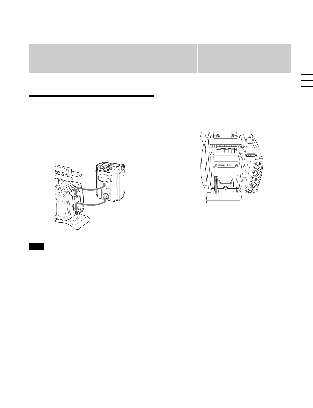
2-1 Mounting the SR-R4
The SR-R4 docks on the rear of the camera head.
For details about mounting the SR-R4, refer to the
Operation Manual of the SR-R4.
SR-R4
Chapter
• The recorder connector for connecting the SR-R4 is an
optical connector. Attach the connector cap on the
optical connector when not connected to an SR-R4 to
protect the connector. After removing the cap, store it in
the position shown in the following figure for
safekeeping.
• When mounting the SR-R4, fix the camera head on a
tripod in advance to keep the camera head stable.
2
Chapter 2 Installation and Preparations
Notes
• SR-R4/SRK-CP1 software V3.00 or later is required in
order to use the various functions described in this
manual.
• Always turn off the camera power supply when
mounting the SR-R4.
For tripod mounting, see “2-5 Mounting the Camera on
a Tripod” (page 22).
• When the camera is used with the SR-R4 docked, make
sure that the camera is securely fixed and stable so that it
will not fall over.
Mounting the SR-R4
17
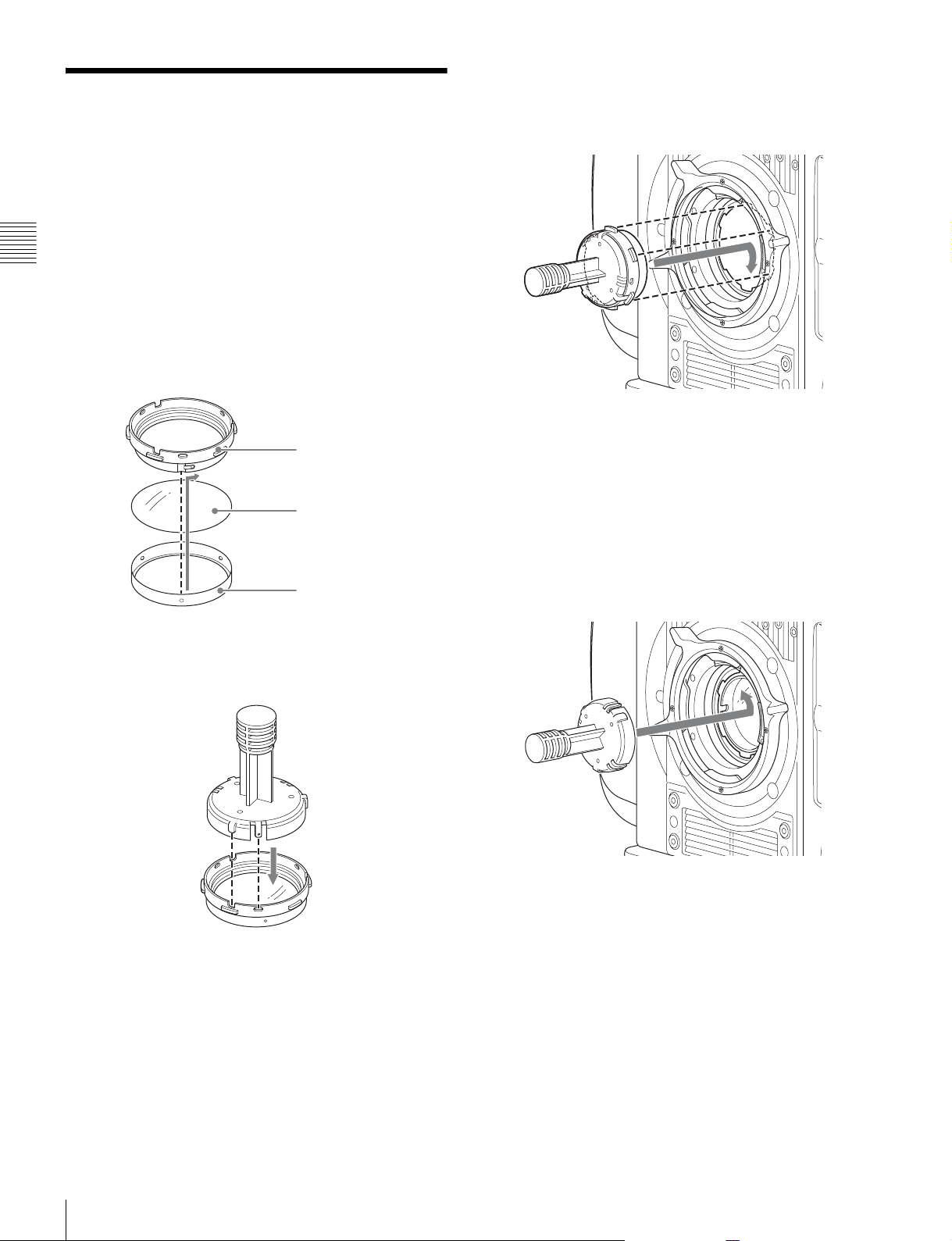
2-2 Attaching a Filter
You can mount commercially available gel filters in the
supplied filter holder and then attach them to the camera if
you wish to use an ND filter in F65RAW-HFR mode or
wish to use a filter other than those built into the camera.
Recommended filter: Fujifilm neutral density filters
Chapter 2 Installation and Preparations
1
Place the filter template (metallic disc) on the gel filter,
then trim the filter around the edge of the filter
template.
2
Remove the ring from the filter holder, place the filter
on the ring, and then attach the holder.
4
Align the notch on the filter mount with the protrusion
on the filter holder, insert the mounting tool onto the
filter mount, and then turn clockwise until it clicks into
place.
5
Pull the mounting tool straight off.
Filter holder
Filter
Ring
3
Align the protrusion on the mounting tool with the
notch on the filter holder, then insert the holder into the
tool.
The mounting tool separates from the camera, and the
filter is mounted in place.
To remove the filter
1
Align the protrusion on the mounting tool with the
notch on the filter holder, then press the tool onto the
filter mount.
Press the tool until it clicks into place.
2
Rotate the mounting tool counterclockwise, then lift
the tool off the camera.
18
The filter holder is removed with the mounting tool.
Attaching a Filter
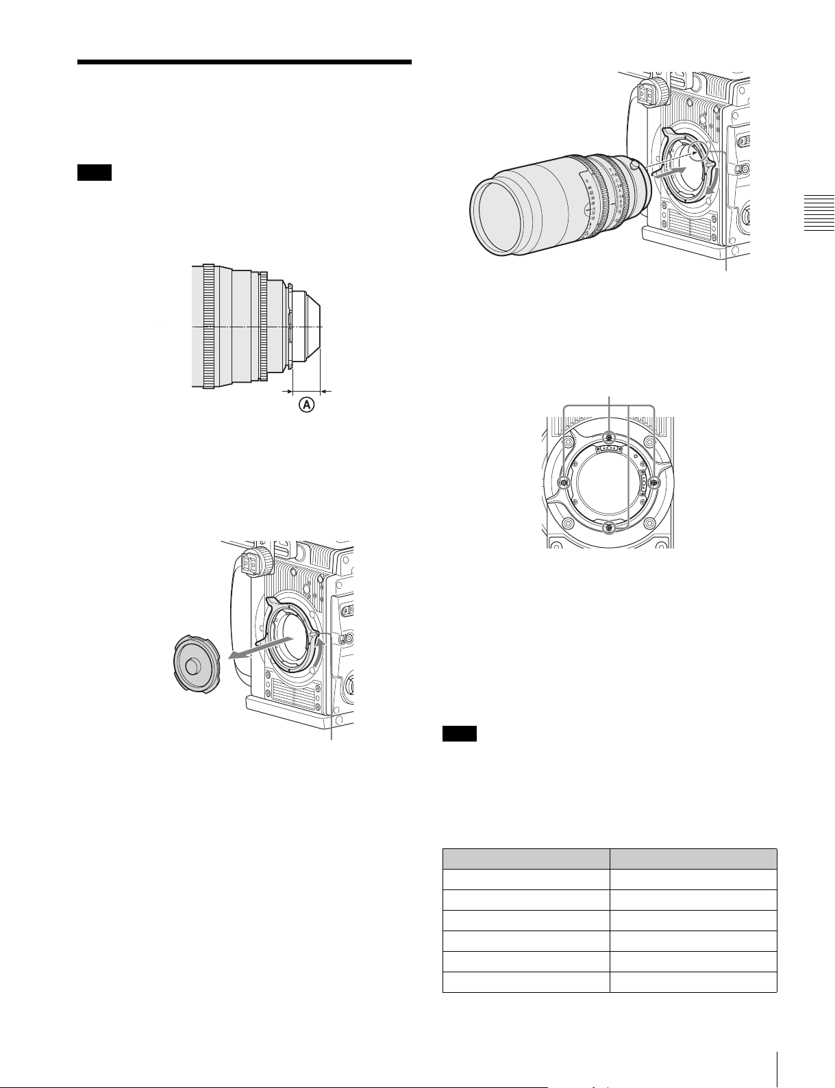
2-3 Attaching a Lens
Attach a lens that conforms to the PL lens mount.
Note
Always use a lens whose projection from the flange (A in
the figure) is less than 31.5 mm (1
that protrudes more than 31.5 mm (1
the internal filter.
For information on handling lenses, refer to the operation
manual for the lens.
1
/4 inch). Use of any lens
1
/4 inch) will damage
Chapter 2 Installation and Preparations
Lens alignment pin
Changing the position of the lens fixing lever
Remove the four screws from the face of the lens fixing
lever indicated in the figure. Change the position of the
fixing lever, reinsert the screws and securely tighten.
Remove screws
1
Rotate the lens fixing lever counterclockwise and
remove the lens mount cap from the lens mount.
Lens fixing lever
2
Align the lens’ alignment pin with the notch in the
upper part of the lens mount and insert the lens into the
mount.
3
While supporting the lens, rotate the lens fixing lever
clockwise to secure the lens.
Adjusting the flange focal length
The optical section uses materials not susceptible to
thermal expansion, so flange back adjustment is generally
not required. However, if you want to make an adjustment,
remove the lens mount and replace the shim with one of the
appropriate thickness. At shipment, a 0.05 mm
(0.0020 inch) shim is installed. The following replacement
shims are available.
Note
When using the camera in HFR mode, the lens distance
indicator may be slightly off, but this is not a malfunction.
For information about replacing shims, consult your local
Sony representative.
Part number Thickness
4-260-711-03 0.02 mm (0.0008 inch)
4-260-711-13 0.03 mm (0.0012 inch)
4-260-711-23 0.04 mm (0.0016 inch)
4-260-711-33 (standard) 0.05 mm (0.0020 inch)
4-260-711-43 0.06 mm (0.0024 inch)
4-260-711-53 0.07 mm (0.0028 inch)
Attaching a Lens
19
Part number Thickness
4-260-711-63 0.08 mm (0.0032 inch)
4-260-711-73 0.09 mm (0.0036 inch)
4-260-711-83 0.10 mm (0.0040 inch)
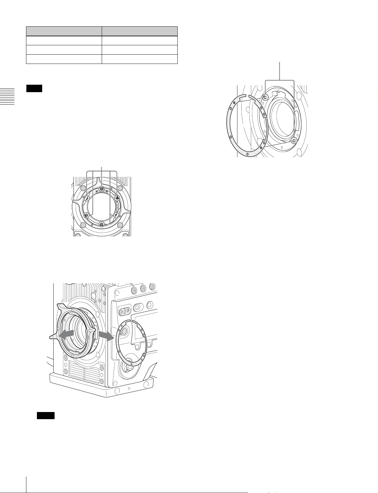
To change a shim
Note
Exercise care not to damage the internal wiring of the
Chapter 2 Installation and Preparations
camera when changing the shim. Modifying a shim,
scratching a surface, or introducing dust can change the
flange back distance and damage the camera such that it
cannot be restored to original condition, just as for a film
camera.
1
Remove the lens mount screws (6).
Lens mount screws
3
Insert the replacement shim using the shim slit to clear
the wiring, and align the camera screw holes and shim
alignment pins.
Shim alignment pins
4
Reattach the lens mount in its original position, and
fasten the screws to a torque of 0.53 N·m (0.39 lbf).
2
Pull the lens mount out by about 10 mm (13/32 inch)
and remove the shim carefully.
Pass the shim slit over the wiring, taking care not to
pull the wiring, when removing the shim.
Note
Pulling the lens mount out by more than 20 mm
3
(
/4 inch) risks damage to the internal wiring.
20
Attaching a Lens
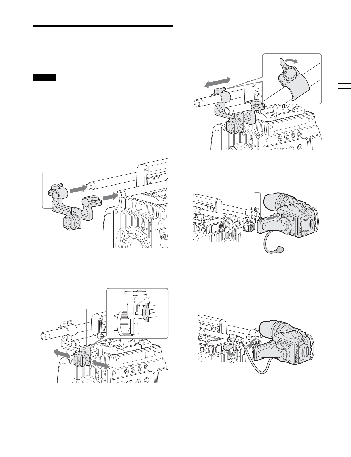
2-4 Attaching a Viewfinder
Caution
When the viewfinder is attached, do not leave the camera
with the eyepiece facing the sun. Direct sunlight can enter
through the eyepiece, be focused in the viewfinder and
cause fire.
For details on the viewfinder, refer to the instruction
manual of the viewfinder.
1
Pass the viewfinder mounting plate over the two rods.
Viewfinder mounting plate
3
Slide the viewfinder mounting plate forward/backward
into position, and then turn the lever to lock it into
position.
4
Fit the viewfinder to the viewfinder shoe and slide the
viewfinder horizontally.
The viewfinder stopper automatically pops down.
Stopper
Chapter 2 Installation and Preparations
2
Slide the slide panel left/right into position, and then
turn the lever on the rear of the slide panel to lock it
into position.
Slide panel
5
Set the viewfinder to the most convenient position,
tighten the viewfinder positioning ring (1 in the
figure below), and connect the viewfinder cable to the
VF connector of the camera (2 in the figure below).
When connecting the DVF-EL100, connect to the 26pin VF connector (page 13) on the left panel.
To detach the viewfinder
Loosen the viewfinder positioning ring, pull up the
viewfinder stopper, then pull out the viewfinder by sliding
it in the direction opposite than when attaching.
Attaching a Viewfinder
21
2-5 Mounting the Camera
2-6 Mounting the
on a Tripod
The camera mounts on a tripod using two 3/8" tripod
receptacles that fit into the base of the camera head.
For details about mounting on a tripod, refer to the
Chapter 2 Installation and Preparations
operation manual of the tripod.
Tripod receptacles
Notes
• Select an appropriate hole, considering the balance of the
weight of the camera. If an inappropriate hole is selected,
the camera may fall over.
• Check that the size of the selected hole matches that of
the screw of the tripod. If they do not match, the camera
cannot be attached to the tripod securely.
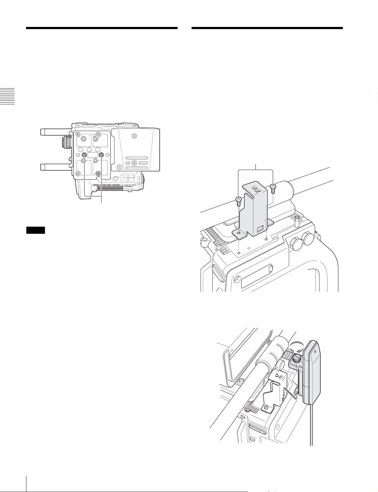
CBK-WA01
A CBK-WA01 Wi-Fi Adapter can be mounted on the
camera using an optional Wi-Fi mounting bracket (part
number: 4-418-596-01) for connecting Wi-Fi capable
devices to the camera.
For information about obtaining the Wi-Fi mounting
bracket, consult your local Sony representative.
1
Attach the Wi-Fi mounting bracket onto the camera
using the supplied +B3 × 5 screws.
M3 × 5 (+B3 × 5 screws) (supplied)
Mounting the Camera on a Tripod / Mounting the CBK-WA01
22
2
Place the protrusions on the rear of the CBK-WA01
into the holes in the mounting bracket, and fasten the
screw to secure the CBK-WA01 to the bracket.
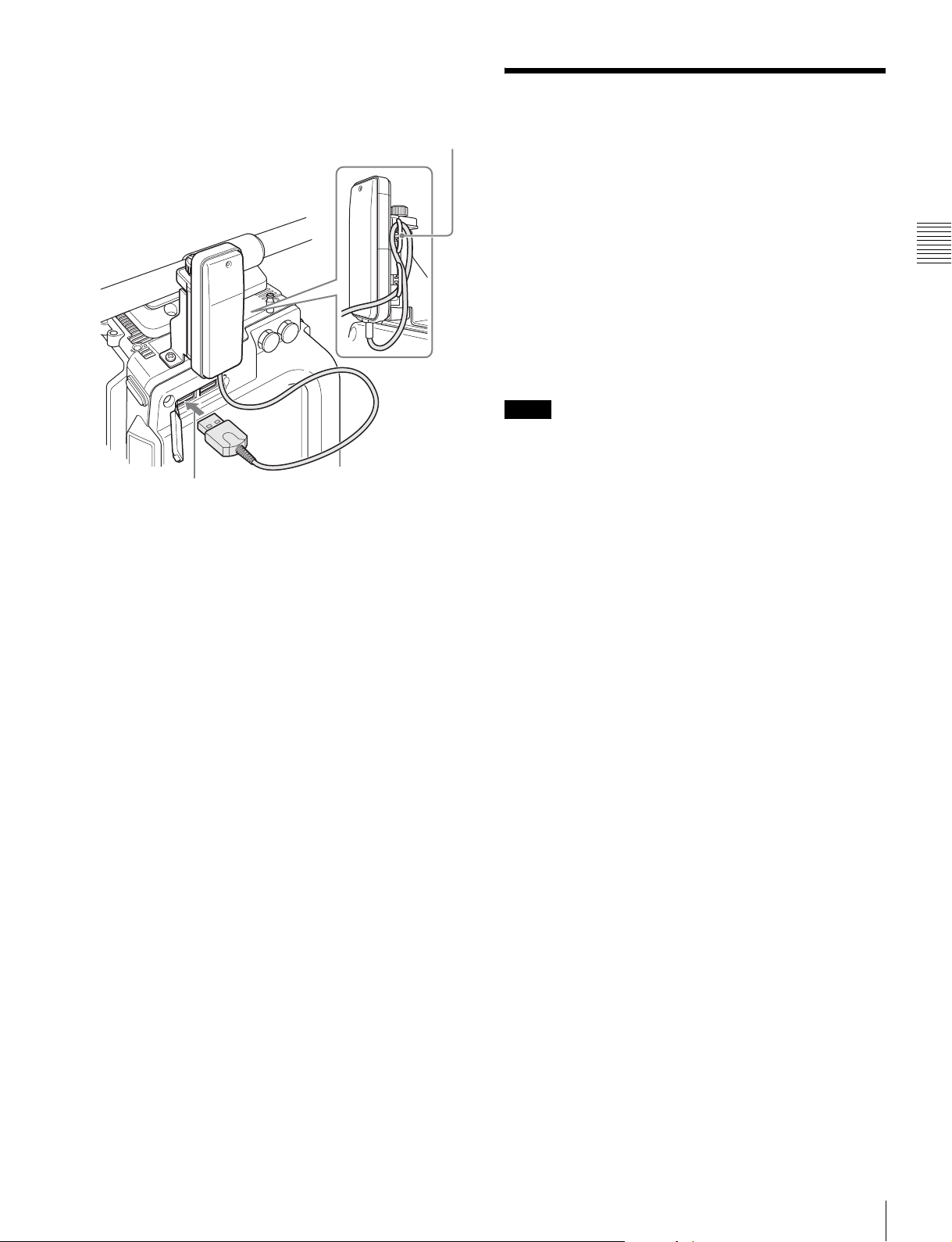
3
Connect the CBK-WA01 cable to a USB connector on
the camera. Wrap excess cable length around the cable
holder.
Cable holder
2-7 Preparing the Power Supply
This camera operates at 12 V DC (10.5 V to 17 V).
To supply power to the camera, attach the supplied 8-pin
power cable connector to a commercially available
shielded cable, and then connect the cable to the DC IN
connector (LEMO 8-pin) on the camera.
For details on connector pin assignments, see “Connector
Pin Assignments” (page 74) in the Appendix. For details
on the pin connections, consult your local Sony
representative.
Notes
• Use of a power supply with 150 W or higher supply
capacity is recommended to safely drive the camera. The
specifications for the power supply cable should be
chosen such that the voltage drop is less than 2 V.
Example: If a 5-meter (16 ft 5 in.) AWG 18 × 3 cable is
used to supply the camera and SR-R4, the voltage drop
will be 0.5 to 1.0 V.
• If using the camera’s 24 V DC output to drive
peripherals, 12 V DC and 24 V DC power supplies must
be connected to the camera via the DC IN connector
(LEMO 8-pin) of the power cable (supplied).
• When using the SR-R4 docked on the camera, the
connection of a 13 V to 17 V DC power source is
recommended.
Chapter 2 Installation and Preparations
To turn on the camera
Set the CAM POWER switch to the ON position, and the
camera is turned on.
Power is also supplied to viewfinder connected to the VF
connector.
12 V or 24 V power can be fed to accessories via the DC
OUT connectors. To supply 24 V power to accessories,
12 V and 24 V DC input power supplies must be connected
via the DC IN connector of the camera.
For the pin assignment for the 24 V power supply DC IN
connector, see “Connector Pin Assignments” (page 74) in
the Appendix.
Preparing the Power Supply
23
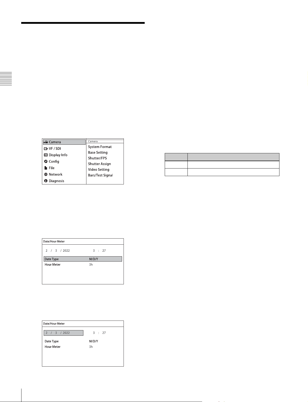
2-8 Setting the Date and Time
When the camera is used for the first time, the menu for
setting the date and time is displayed in the viewfinder. Set
the current date and time on the <Date/Hour Meter> page
in the Config menu.
Chapter 2 Installation and Preparations
To set the menu using a monitor screen, connect a monitor
to an SDI OUT connector.
1
Turn on the camera power supply.
2
Press the VF MENU button.
The menu appears in the viewfinder.
6
Turn the MENU SEL/ENTER dial to set the date (year,
month, day).
Turning the MENU SEL/ENTER dial moves to the
next digit. Select the day, then press the MENU SEL/
ENTER dial to confirm the setting.
7
Turn the MENU SEL/ENTER dial to select Time, then
press the MENU SEL/ENTER dial.
The time becomes editable.
8
Turn the MENU SEL/ENTER dial to set the time, then
press the MENU SEL/ENTER dial.
9
Turn the MENU SEL/ENTER dial to select Date Type,
then press the MENU SEL/ENTER dial.
10
Turn the MENU SEL/ENTER dial to select the date
format, then press the MENU SEL/ENTER dial.
You can select one of the following display formats.
Setting Example display (18th December, 2013)
M/D/Y 12/18/2013
M/D 12/18
3
Turn the MENU SEL/ENTER dial to select Config,
then press the MENU SEL/ENTER dial.
4
Turn the MENU SEL/ENTER dial to select Date/Hour
Meter, then press the MENU SEL/ENTER dial.
The <Date/Hour Meter> page appears.
5
Turn the MENU SEL/ENTER dial to select Date, then
press the MENU SEL/ENTER dial.
The date becomes editable.
11
When finished, press the VF MENU button to exit
menu operation.
Setting the Date and Time
24

Basic Adjustments and
Settings
3-1 Basic Operation of the Camera
The camera operates in two modes: Cine mode and
Custom mode. In Cine mode, the camera acquires main
line video information, without processing, for color
grading in post-production while applying basic grading to
the VF and SDI outputs. In Custom mode, images are
created on location by adjusting the black/white level and
gain of the main line signal.
Cine mode
• Shoots images with a fixed camera gain, and sensitivity
specified using a light meter (EI mode).
• Sensitivity can be selected from 200EI, 250EI, 320EI,
400EI, 500EI, 640EI, 800EI, 1000EI, 1250EI, 1600EI,
2000EI, 2500EI, and 3200EI.
• In post-production, the gain can be set to the sensitivity
selected during shooting.
• In intensified sensitivity shooting (e.g. 1600EI), the gain
is automatically adjusted in response to the selected
sensitivity for the VF/SDI/HD-Y outputs, even though
the master video output darkens, to maintain appropriate
monitoring levels.
• In HD mode, the video gamma can be set to S-Log2 or
selected from user gammas.
• Video adjustment using ASC CDL is supported for the
SDI1 output. The adjustments are recorded as metadata
together with the video for each frame. The video
adjustments made during shooting can be recreated in
post production by applying the metadata values to the
video.
• The full latitude does not change when the sensitivity
setting is changed, but the dynamic range and noise floor
changes in post-production with suitable processing.
When the sensitivity is set high, the dynamic range
increases on one hand, while the noise in dark areas also
increases. Conversely, when the sensitivity is set low, the
dynamic range decreases but the noise in the dark areas
also decreases.
Chapter
Custom mode
This mode allows camera gain to be adjusted and black/
white level to be adjusted from the camera menu or
optional remote control unit (RM) while shooting.
• Camera gain is adjustable in the range –6 dB to +12 dB
in 3 dB increments (EI adjustment not supported).
• Black/white level is adjustable.
• Black/White, Gain, and following operations can be
controlled from a remote control unit.
—Shutter Speed
—Filter Select
—Rec Start/Stop
—Rec Review
—Bars/Test Signal
—12p Iris Control
The white balance can be set to 3200K (tungsten), 4300K
(tungsten), or 5500K (daylight).
The camera supports HD mode recording, where images
are down-converted to HD internally and recorded on the
SR-R4. The recording format can be selected between HD
mode and F65RAW mode.
Functions supported after upgrading the
F65 using the CBK-65EL (F65 UPGRADE
KIT)
DVF-EL100 digital viewfinder connection and
control
Supports cable connection to the DVF-EL100 digital
viewfinder. Control from the viewfinder also supported
using buttons on the DVF-EL100.
Note
To reduce OLED burn-in, use the DVF-EL100 switch to
turn VF DISPLAY (viewfinder display function) On/Off.
Independent, SDI1/SDI2 2-system signal
operation
Supports selection of separate tone, color, and character
text overlay for output. SDI1 is intended primarily for the
director, and SDI2 is intended primarily for the camera
operator.
3
Chapter 3 Basic Adjustments and Settings
Basic Operation of the Camera
25
3-2 Camera Settings
1
The camera can be configured from the following devices.
3-3 Basic Settings using the Subdisplay
Subdisplay
You perform the basic setup configuration using the
subdisplay on the side of the camera head.
The basic settings (settings page) is displayed on the
subdisplay when power is applied to the camera. Press and
hold the SETTING button for 1 second or longer to switch
to Settings Change mode. The MENU SEL/ENTER dial,
SETTING button and BACK button are used for Settings
Chapter 3 Basic Adjustments and Settings
Change mode operation.
For details about settings on the subdisplay, see “3-3 Basic
Settings using the Subdisplay” (page 26). For details about
the subdisplay menu list, see “4-1 Subdisplay Menu List”
(page 43).
Viewfinder or monitor
Detailed settings can be performed by displaying the menu
(VF menu) in the viewfinder or on a monitor connected to
an SDI OUT connector.
Press the VF MENU button on the side of the camera to
display the VF menu in the viewfinder or on a monitor. The
VF MENU button, MENU SEL/ENTER dial, and BACK
button are used for VF menu operation.
For details about VF menu operations, see “3-4 VF Menu
Basic Operation” (page 35). For details about the VF
menu list, see “4-2 VF Menu List” (page 46).
Web browser
If the camera is connected to a network, the menus can be
displayed in a web browser on a computer. The settings
displayed are almost identical to the display in the
viewfinder or on a monitor.
Basic settings of the camera can be easily performed using
the subdisplay. The items set on the subdisplay can also be
set using the VF menu.
3-3-1 Basic Operation of the Subdisplay
The buttons and dial shown below are used for operation of
the subdisplay.
Side panel of the camera head
Subdisplay
SETTING button
PAGE button
BACK button
MENU SEL/ENTER dial
To display the settings pages
After the camera is turned on, the startup screen is
displayed on the subdisplay for several seconds, after
which the settings page is displayed.
For details about web browser operations, see “Menu
Operation using a Web Browser” (page 77).
Tablet device
If the camera is used with the optional Wi-Fi adapter
(CBK-WA01), the menus can be displayed on a tablet
device, such as an iPad, via a wireless LAN. The settings
displayed are almost identical to the display in the
viewfinder or on a monitor.
For details about tablet device operations, see “Operation
using a Tablet Device” (page 77).
Camera Settings / Basic Settings using the Subdisplay
26
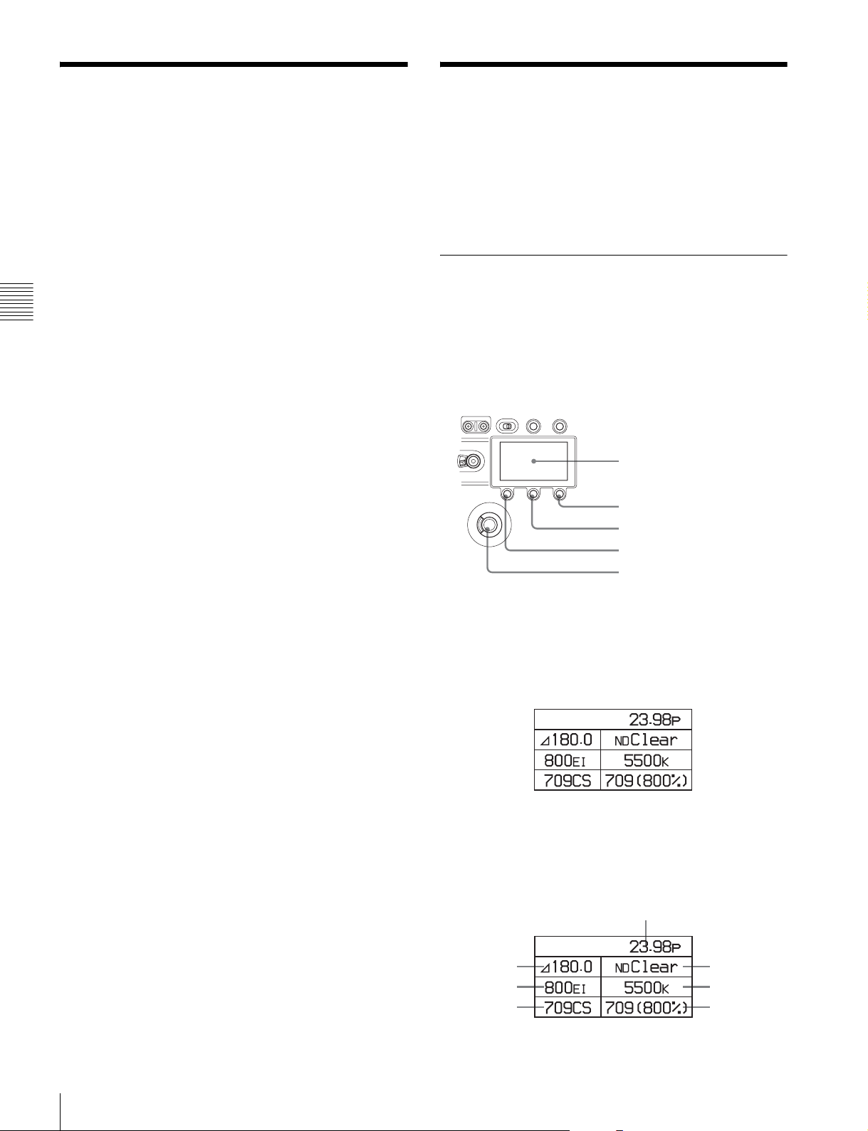
Pressing the PAGE button advances to the next page.
The following items can be set or checked on each settings
page.
Settings page 1
23
4
6
5
7
1 Video format
2 Shutter value
3 ND filter
4 Sensitivity (EI value)
5 Color temperature
6 Color space (SDI2)
7 LUT (SDI2)
Select screen (e.g. shutter value)
Settings page 2
1
3
5
1 Vo l t a g e s
2 Fan operating mode
3 Reel number
4 Media remaining
5 File name
6 Time code
Settings page 3
12
34
56
1 ASSIGN button 1
2 ASSIGN button 2
3 ASSIGN button 3
4 ASSIGN button 4
5 Subdisplay brightness
6 Self diagnostics
6
2
4
On this screen, turn the MENU SEL/ENTER dial to select
an item. Press the MENU SEL/ENTER dial to display the
change screen for the item.
Change screen (e.g. shutter value)
Chapter 3 Basic Adjustments and Settings
The current value of the setting is displayed at the top right
of the screen. Turn the MENU SEL/ENTER dial to select
the value, then press the MENU SEL/ENTER dial.
The value for the selected item is entered.
To cancel a changed setting
Press the BACK button before confirming the changed
setting.
The setting is restored to the original value, and the display
returns to the previous page.
Note
Pressing the VF MENU button enables menu operation in
the viewfinder or on a monitor, and disables operation
using the subdisplay.
Subdisplay when VF MENU button is pressed
To change a setting
Press and hold the SETTING button for 1 second or longer.
The screen changes to Settings Change mode, and the
selected item is displayed in inverse text.
In this mode, the item you want to set is selected by turning
the MENU SEL/ENTER dial. When the item you want to
set is shown in inverse text, press the MENU SEL/ENTER
dial.
Where there are multiple configuration items, the select
screen is displayed.
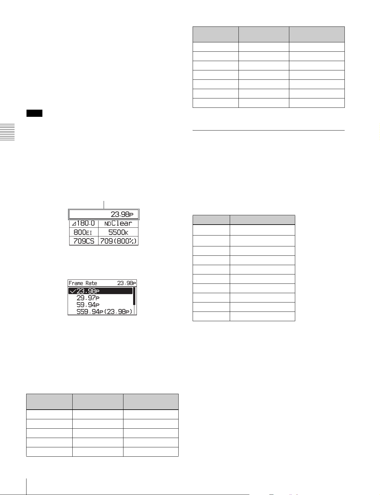
3-3-2 Setting the Video Format
The camera supports the following video format settings.
F65RAW mode:
23.98p, 24p, 29.97p, 25p, 50p, 59.94p, S47.95
(23.98p), S48 (24p), S59.94p (23.98p), S59.94p
(29.97p), S60p (24p), S60p (25p)
HD mode (4:4:4 RGB):
23.98p, 29.97p, 24p, 25p, S59.94p (23.98p), S59.94p
(29.97p), S60p (24p), S60p (25p)
HD mode (4:2:2 YCbCr):
23.98p, 29.97p, 24p, 25p, 50p, 59.94p, S59.94p
(23.98p), S59.94p (29.97p), S60p (24p), S60p (25p)
Basic Settings using the Subdisplay
27
F65RAW-HFR mode:
23.98pForPB, 29.97pForPB, 24pForPB, 25pForPB,
S119.88p (23.98p), S119.88p (29.97p), S120p (24p),
S120p (25p)
The mode can be switched between F65RAW mode, HD
mode, and F65RAW-HFR mode on the <System Format>
page in the VF menu.
For details, see “3-5 Setting the Shooting Mode” (page
37).
Note
It is recommended that the power be turned off and back
on again after changing the video format.
Chapter 3 Basic Adjustments and Settings
Changing the video format
1
Select the video format on settings page 1, then press
the MENU SEL/ENTER dial.
Settings page 1
Video format
Camera image VF connector
output
59.94p 59.94i* 59.94i*
S47.95p 23.98PsF* 23.98PsF*
S48 24PsF* 24PsF*
S59.94p 59.94i* 59.94i*
S60p 60i* 60i*
S119.88p 59.94i* 59.94i*
S120p 60i* 60i*
a) The output image scan type can be set to Interlace or Frame Drop.
SDI OUT connector
output
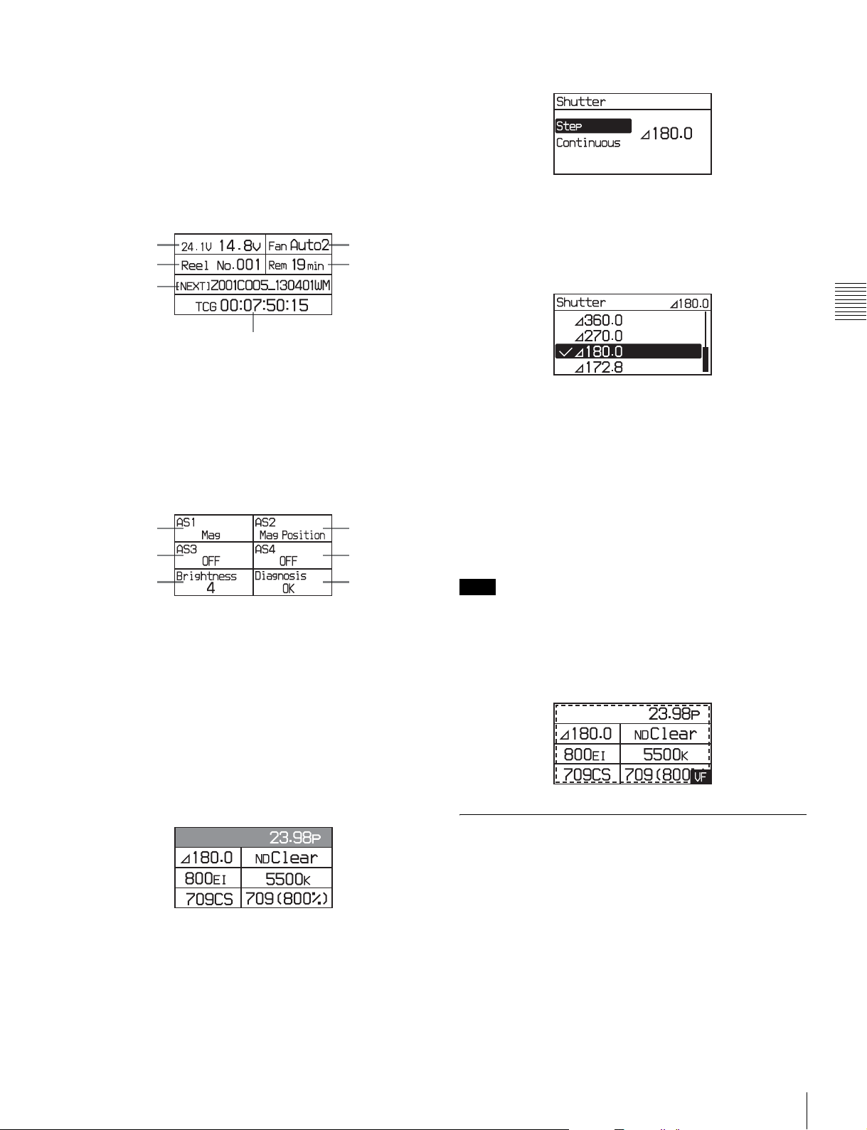
3-3-3 Setting the Shutter Value
The shutter of the camera can be viewed and adjusted, with
settings displayed as shutter angles, just as for a film
camera. Two operation methods are available for the
adjustment: stepwise and continuous.
Step mode
Frequently-used shutter angle values can be selected,
enabling step selection of the shutter values.
2
Turn the MENU SEL/ENTER dial to select the video
format, and press the MENU SEL/ENTER dial.
To set using the VF menu
Set on the <System Format> page in the Camera menu
(page 47).
VF and SDI OUT connectors output format
Setting the camera main video format automatically
determines the signal format that is output on the VF and
SDI OUT connectors.
Camera image VF connector
output
23.98p 23.98PsF 23.98PsF
29.97p 29.97PsF 29.97PsF
24p 24PsF 24PsF
25p 25PsF 25PsF
50p 50i* 50i*
SDI OUT connector
output
Step No. Shutter angle
1
2
3 180.0
4 172.8
5 150.0
6 144.0
790.0
845.0
922.5
10 11.2
a) Selectable for the electronic shutter only.
360.0
270.0
a)
a)
The corresponding shutter speeds vary according to the
frame frequency and frame rate of the selected video
format.
Continuous mode
The shutter value can be changed smoothly in continuous
mode in the range 4.2° to 360.0° (electronic shutter) or
11.2° to 180.0° (mechanical rotary shutter).
To obtain your desired shutter value quickly, select a value
nearest your desired one in Step mode, then switch to
Continuous mode and adjust the shutter value.
Basic Settings using the Subdisplay
28
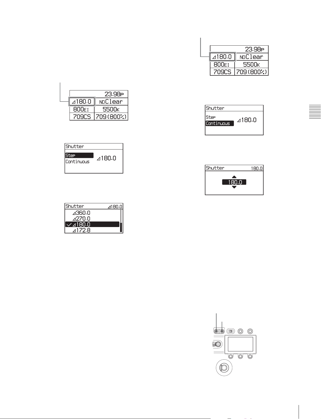
Changing the shutter value in Step mode
In Step mode, one of the registered shutter values can be
selected.
1
Select the shutter value on settings page 1, then press
the MENU SEL/ENTER dial.
Settings page 1
Settings page 1
Shutter value
Shutter value
2
Select [Step], then press the MENU SEL/ENTER dial.
3
Turn the MENU SEL/ENTER dial to select the shutter
value.
2
Select [Continuous], then press the MENU SEL/
ENTER dial.
3
Turn the MENU SEL/ENTER dial to select the shutter
value.
You do not need to press the MENU SEL/ENTER dial to
set a value. The shutter value changes are reflected on the
camera as the MENU SEL/ENTER dial is turned. Pressing
the BACK button cancels the shutter setting, and restores
the previous value.
Chapter 3 Basic Adjustments and Settings
Pressing the MENU SEL/ENTER dial confirms the
setting, and reflects the changed value on the camera.
Pressing the BACK button cancels the shutter setting, and
restores the previous value.
To set using the VF menu
Set on the <Shutter/FPS> page in the Camera menu (page
47).
Selecting an arbitrary shutter value
In Continuous mode, an arbitrary shutter value can be set.
1
Select the shutter value on settings page 1, then press
the MENU SEL/ENTER dial.
To set using the VF menu
Set on the <Shutter/FPS> page in the Camera menu (page
47).
When not using the shutter
Press the E. button or M. button, whichever is lit, on the
SHUTTER button for one second or longer. The shutter
switches off and the light on both SHUTTER buttons go
out.
M. button
E. button
Basic Settings using the Subdisplay
29
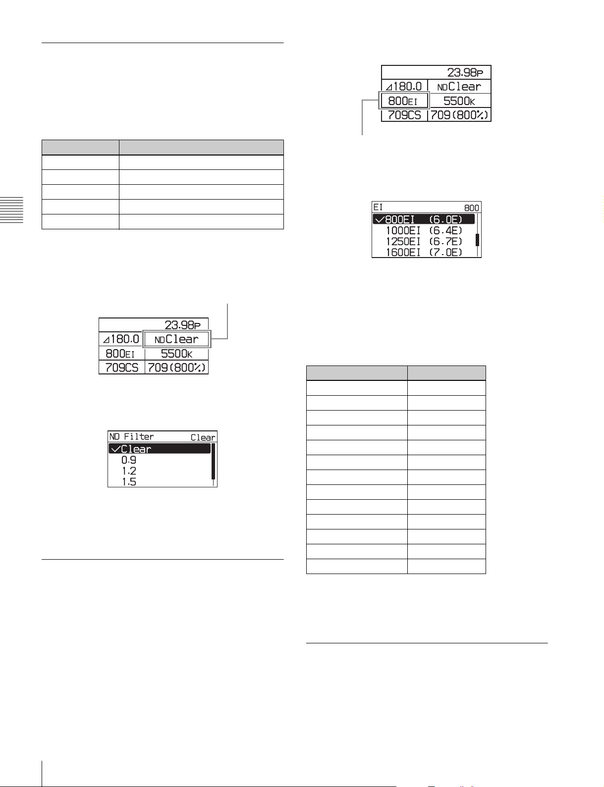
3-3-4 Selecting an ND Filter
The camera has built-in optical ND filters that can be used
to match the illumination and natural lighting conditions.
The following filters can be selected in F65RAW mode or
HD mode. In F65RAW-HFR mode, the filter is fixed to
Clear.
Filter density Description
Clear No filter is used.
0.9 1/8 optical transmittance
1.2 1/16 optical transmittance
1.5 1/32 optical transmittance
1.8 1/64 optical transmittance
Chapter 3 Basic Adjustments and Settings
1
Select the ND filter on settings page 1, and press the
MENU SEL/ENTER dial.
Settings page 1
ND filter
Settings page 1
Sensitivity
2
Turn the MENU SEL/ENTER dial to select the EI
value, then press the MENU SEL/ENTER dial.
To set using the VF menu
Set the Exposure Index on the <Base Setting> page in the
Camera menu (page 47).
Latitude values
The latitude is automatically assigned one of the following
values, depending on the sensitivity setting.
2
Turn the MENU SEL/ENTER dial to select the ND
filter, then press the MENU SEL/ENTER dial.
To set using the VF menu
Set the ND Filter on the <Base Setting> page in the
Camera menu (page 47).
3-3-5 Setting the Sensitivity (EI Value) (Cine Mode)
The sensitivity is determined by the EI value (Exposure
Index). The viewfinder and monitor image brightness
changes to match the EI value. But it has no affect on the
recorded image.
The camera supports the following sensitivity settings:
200EI, 250EI, 320EI, 400EI, 500EI, 640EI, 800EI,
1000EI, 1250EI, 1600EI, 2000EI, 2500EI, and 3200EI.
1
Select the sensitivity on settings page 1, then press the
MENU SEL/ENTER dial.
Sensitivity (EI value) Latitude
200EI 4.0E
250EI 4.4E
320EI 4.7E
400EI 5.0E
500EI 5.4E
640EI 5.7E
800EI 6.0E
1000EI 6.4E
1250EI 6.7E
1600EI 7.0E
2000EI 7.4E
2500EI 7.7E
3200EI 8.0E
The value is displayed in “xxEI” format and represents the
highlight latitude displayed as a lens aperture value (fstop) for key light from a gray chart with 18% reflectivity.
3-3-6 Setting the Color Temperature
The color temperature can be set to 3200K (tungsten),
4300K (tungsten), or 5500K (daylight) to match the
shooting environment.
Basic Settings using the Subdisplay
30
 Loading...