

Sony CAVM-1000-ES Service manual
CAV-M1000ES
SERVICE MANUAL
Ver. 1.2 2004. 10
SPECIFICATIONS
CAV-M1000ES Main Unit
Audio (each channel)
Continuous average power output (FTC)
All channels: 30 W per channel min. RMS at 8
ohms, any two channels driven
from 20 Hz to 20 kHz with no
more than 0.09 % THD.
40 W per channel min. RMS at 4
ohms, any two channels driven
from 20 Hz to 20 kHz with no
more than 0.7 % THD.
Frequency response: 5 Hz to 70 kHz ± 3dB
Input sensitivity: 160 mV for 1 W output, 650 mV for
full output (30 W) with volume
control set to maximum.
Input impedance: 20 k ohms
Signal-to-noise ratio: 92 dB (A-weighted )
Bass control range: 100 Hz ± 14 dB, 2 dB step
Treble control range: 10 kHz ± 14 dB, 2 dB step
SOURCE 1-8 and ZONE 1-6 AUDIO OUT
Frequency response: 5 Hz to 55 kHz ± 3dB
THD @ 2 V: 0.08 %
Signal-to-noise ratio: 102 dB (A-weighted @ 2 V)
General
12V trigger: 300 mA max each zone,
total 1.2 A max
Power requirements: 120 V 60 Hz
Power consumption: 540 W
Dimensions: 430 × 175 × 433 mm
(16
(w/h/d)
Mass: 24 kg (52 lbs 15 oz)
RM-TP100 RF Remote Control
Interface system: Liquid crystal touch panel
Liquid crystal size: 5.2 inches (320 × 240 dots)
Touch panel: Resistance sensible system
Analog type
Maximum range from the RF Antenna:
7 m (22 feet 11
(The maximum range differs
7
/8 × 6 7/8 × 17 1/16 inches)
1
/2 inches)
depending on the environment
where you use the RF Remote
Control.)
US Model
Power supply: Rechargeable (Ni-MH) battery
Maximum external dimensions:
227 × 146 × 45 mm
3
/4 × 1 7/8 inches)
(9 × 5
(w/h/d, including projecting
parts and controls)
Mass: 0.8 kg (1 lbs 13 oz)
(Main unit only, including the
rechargeable battery)
Operating temperature:
5°C to 35°C (41°F to 95°F)
Composition
• CAV-M1000ES Main Unit
• RM-TP100 RF Remote Control
• RMB-TP100 Charger cradle for
the RF Remote Control
• Ferrite core
• AN-M1000 RF Antenna
• AC power cord
• Plug-in 4-terminal screw-type
connector for speaker (6)
• Installation Manual
Design and specifications are subject
to change without notice.
Video
Input/output impedance:
75 ohm
Video insertion loss: 0 dB (50 Hz - 6 MHz)
9-877-752-03
2004J16-1
© 2004.10
Sony Corporation
Audio Group
Published by Sony Engineering Corporation
CUSTOM INTEGRATED AV SYSTEM
CAV-M1000ES
r
SAFETY CHECK-OUT
After correcting the original service problem, perform the following
safety check before releasing the set to the customer:
Check the antenna terminals, metal trim, “metallized” knobs, screws,
and all other exposed metal parts for AC leakage.
Check leakage as described below.
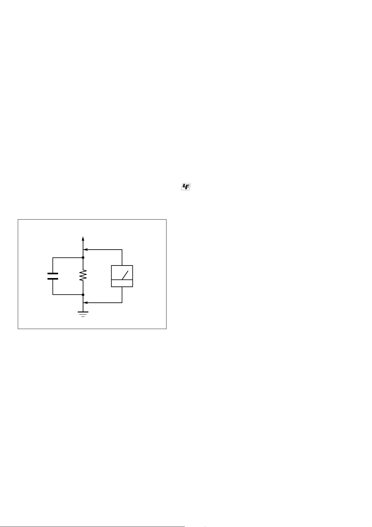
LEAKAGE TEST
The AC leakage from any exposed metal part to earth ground and
from all exposed metal parts to any exposed metal part having a
return to chassis, must not exceed 0.5 mA (500 microamperes.).
Leakage current can be measured by any one of three methods.
1. A commercial leakage tester, such as the Simpson 229 or RCA
WT -540A. Follow the manuf acturers’ instructions to use these
instruments.
2. A battery-operated AC milliammeter . The Data Precision 245
digital multimeter is suitable for this job.
3. Measuring the voltage drop across a resistor by means of a
VOM or battery-operated AC v oltmeter . The “limit” indication
is 0.75 V, so analog meters must have an accurate lo w-voltage
scale. The Simpson 250 and Sanwa SH-63Trd are examples
of a passive VOM that is suitable. Nearly all battery operated
digital multimeters that have a 2 V A C range are suitable. (See
Fig. A)
To Exposed Metal
Parts on Set
AC
0.15 µF
1.5 k
Ω
voltmete
(0.75 V)
Flexible Circuit Board Repairing
• Keep the temperature of the soldering iron around 270 °C
during repairing.
• Do not touch the soldering iron on the same conductor of the
circuit board (within 3 times).
• Be careful not to apply force on the conductor when soldering
or unsoldering.
Notes on chip component replacement
• Never reuse a disconnected chip component.
• Notice that the minus side of a tantalum capacitor may be
damaged by heat.
UNLEADED SOLDER
Boards requiring use of unleaded solder are printed with the leadfree mark (LF) indicating the solder contains no lead.
(Caution: Some printed circuit boards may not come printed with
the lead free mark due to their particular size)
: LEAD FREE MARK
Unleaded solder has the following characteristics.
• Unleaded solder melts at a temperature about 40 °C higher
than ordinary solder.
Ordinary soldering irons can be used but the iron tip has to be
applied to the solder joint for a slightly longer time.
Soldering irons using a temperature regulator should be set to
about 350 °C.
Caution: The printed pattern (copper foil) may peel away if
the heated tip is applied for too long, so be careful!
• Strong viscosity
Unleaded solder is more viscou-s (sticky, less prone to f low)
than ordinary solder so use caution not to let solder bridges
occur such as on IC pins, etc.
• Usable with ordinary solder
It is best to use only unleaded solder but unleaded solder may
also be added to ordinary solder.
Earth Ground
Fig. A. Using an AC voltmeter to check AC leakage.
SAFETY-RELATED COMPONENT WARNING!!
COMPONENTS IDENTIFIED BY MARK 0 OR DOTTED LINE
WITH MARK 0 ON THE SCHEMATIC DIAGRAMS AND IN
THE PARTS LIST ARE CRITICAL TO SAFE OPERATION.
REPLACE THESE COMPONENTS WITH SONY P ARTS WHOSE
PART NUMBERS APPEAR AS SHOWN IN THIS MANUAL OR
IN SUPPLEMENTS PUBLISHED BY SONY.
2

TABLE OF CONTENTS
CAV-M1000ES
1. SERVICING NOTE ................................................... 4
2. GENERAL ................................................................... 8
3. DIAGRAMS
3-1. Block Diagram – MAIN/POWER Section –.................. 14
3-2. Block Diagram – AUDIO I/O Section –......................... 15
3-3. Block Diagram – VIDEO I/O Section – ......................... 16
3-4. Block Diagram
– AMP/SPEAKER/PRE OUT Section –......................... 17
3-5. Block Diagram
– IR OUT/RS232C/12V TRIGGER Section –................ 18
3-6. Block Diagram
– RF REMOTE/RF ANTENNA Section – ...................... 19
3-7. Printed Wiring Board – AMP Section – ......................... 20
3-8. Schematic Diagram – AMP Section – ............................ 21
3-9. Printed Wiring Board
– AMP BASE Section (SIDE A) – .................................. 22
3-10. Printed Wiring Board
– AMP BASE Section (SIDE B) – .................................. 23
3-11. Schematic Diagram – AMP BASE Section – ................. 24
3-12. Printed Wiring Board – AUDIO I/O BRD Section –...... 25
3-13. Schematic Diagram
– AUDIO I/O BRD Section (1/4) – ................................. 26
3-14. Schematic Diagram
– AUDIO I/O BRD Section (2/4) – ................................. 27
3-15. Schematic Diagram
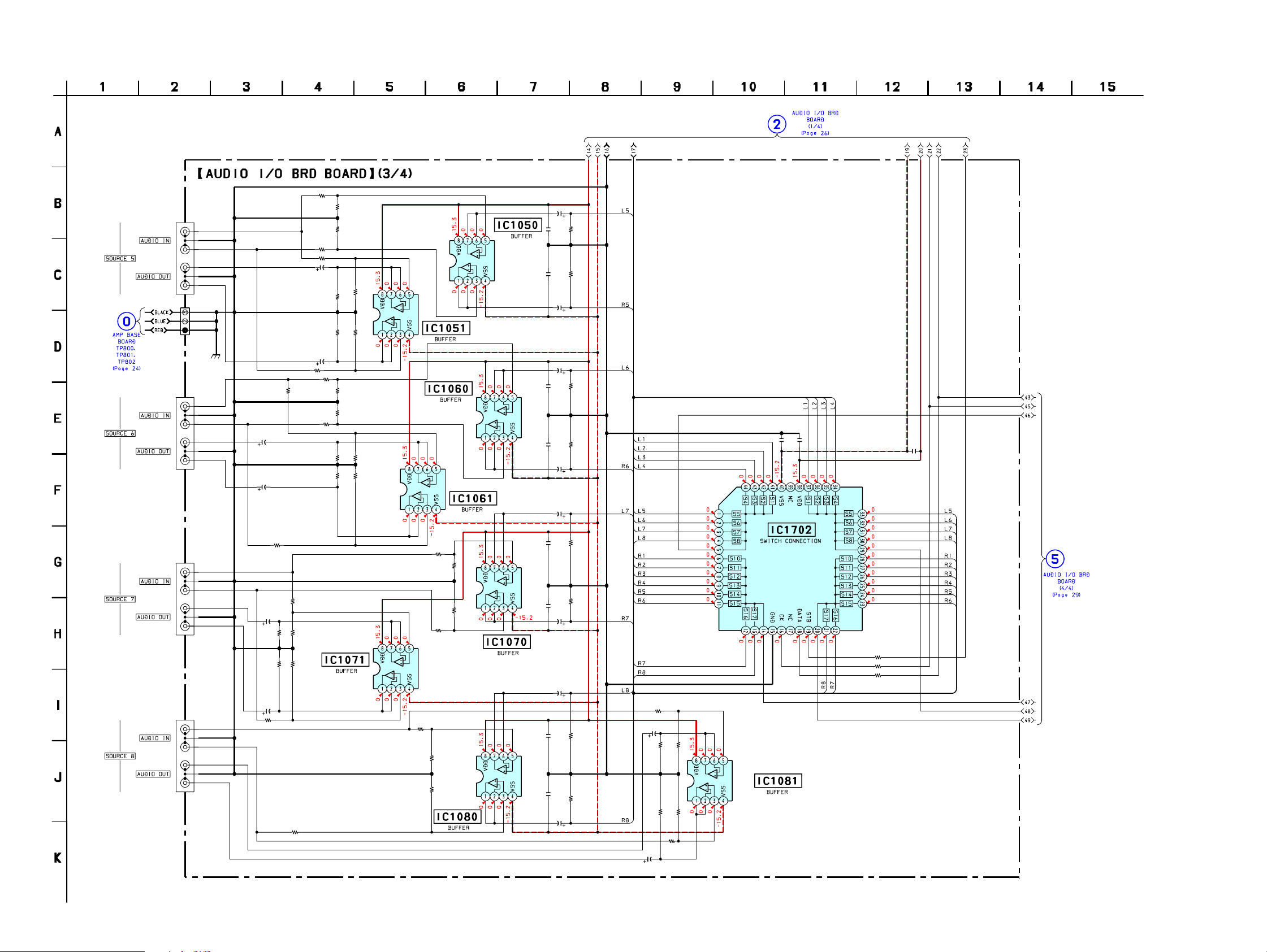
– AUDIO I/O BRD Section (3/4) – ................................. 28
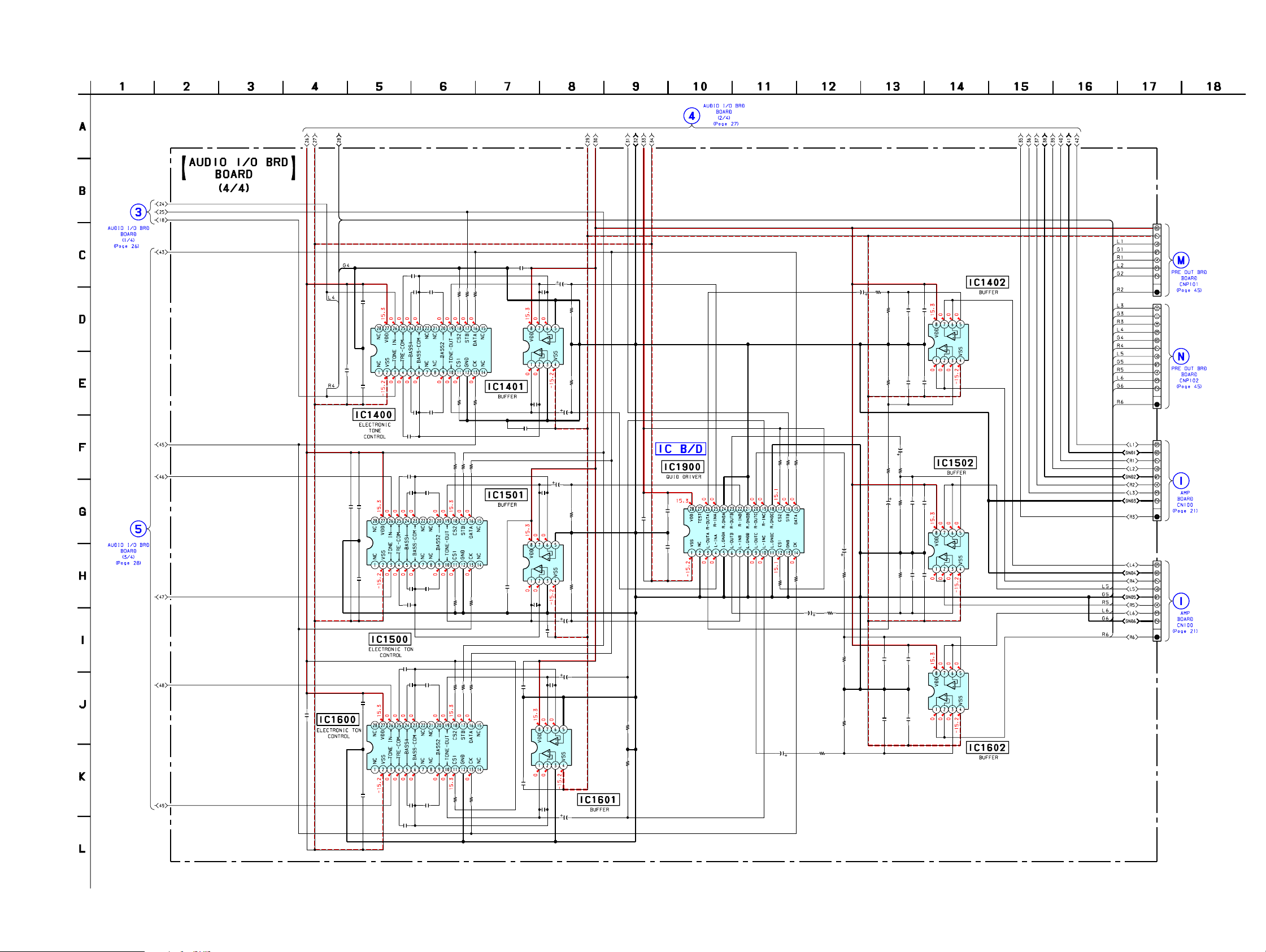
3-16. Schematic Diagram
– AUDIO I/O BRD Section (4/4) – ................................. 29
3-17. Printed Wiring Board – VIDEO I/O BRD Section – ....... 30
3-18. Schematic Diagram
– VIDEO I/O BRD Section (1/2) – ................................. 31
3-19. Schematic Diagram
– VIDEO I/O BRD Section (2/2) – ................................. 32
3-20. Printed Wiring Board
– DISPLAY Section (SIDE A) – ..................................... 33
3-21. Printed Wiring Board
– DISPLAY Section (SIDE B) – ..................................... 34
3-22. Schematic Diagram – DISPLAY Section (1/3) – ............ 35
3-23. Schematic Diagram – DISPLAY Section (2/3) – ............ 36
3-24. Schematic Diagram – DISPLAY Section (3/3) – ............ 37
3-25. Printed Wiring Board – FRONT PANEL Section – ....... 38
3-26. Schematic Diagram – FRONT PANEL Section – .......... 39
3-27. Printed Wiring Board – SPEAKER OUT Section –....... 40
3-28. Schematic Diagram – SPEAKER OUT Section – ......... 41
3-29. Printed Wiring Board – RJ45 Section – ......................... 42
3-30. Schematic Diagram – RJ45 Section – ............................ 43
3-31. Printed Wiring Board – PRE OUT BRD Section –........ 44
3-32. Schematic Diagram – PRE OUT BRD Section –........... 45
3-33. Printed Wiring Board
– RS232C/12V TRIGGER Section – .............................. 46
3-34. Schematic Diagram
– RS232C/12V TRIGGER Section – .............................. 47
3-35. Printed Wiring Board – IR OUT Section – .................... 48
3-36. Schematic Diagram
– IR OUT/CONNECTOR Section – ............................... 49
3-37. Printed Wiring Board – CONNECTOR Section – ......... 50
3-38. Printed Wiring Board – REGULATOR Section –.......... 51
3-39. Schematic Diagram – REGULATOR Section –............. 52
3-40. Printed Wiring Board – AC INLET Section – ................ 53
3-41. Schematic Diagram – AC INLET Section – ................... 54
3-42. Printed Wiring Board
– RF ANTENNA Section (AN-M1000) – ....................... 55
3-43. Schematic Diagram
– RF ANTENNA Section (AN-M1000) – ....................... 55
3-44. Printed Wiring Board
– RF REMOTE CONTROL Section (RM-TP100) – ...... 56
3-45. Schematic Diagram
– RF REMOTE CONTROL Section (RM-TP100) – ...... 57
3-46. Printed Wiring Board
– PA UNIT Section (SIDE A) – ...................................... 58
3-47. Printed Wiring Board
– PA UNIT Section (SIDE B) – ...................................... 59
3-48. Schematic Diagram – PA UNIT Section (1/2) – ............ 60
3-49. Schematic Diagram – PA UNIT Section (2/2) – ............ 61
4. EXPLODED VIEWS
4-1. Overall Section ................................................................ 70
4-2. Front Panel Section ......................................................... 71
4-3. Chassis Section................................................................ 72
4-4. Back Panel Section.......................................................... 73
4-5. RF Remote Control (RM-TP100) Section....................... 74
4-6. Charger Cradle (RMB-TP100) Section........................... 75
4-7. RF Antenna (AN-M1000) Section .................................. 76
5. ELECTRICAL PARTS LIST .................................. 77
3
CAV-M1000ES
SECTION 1
SERVICING NOTE
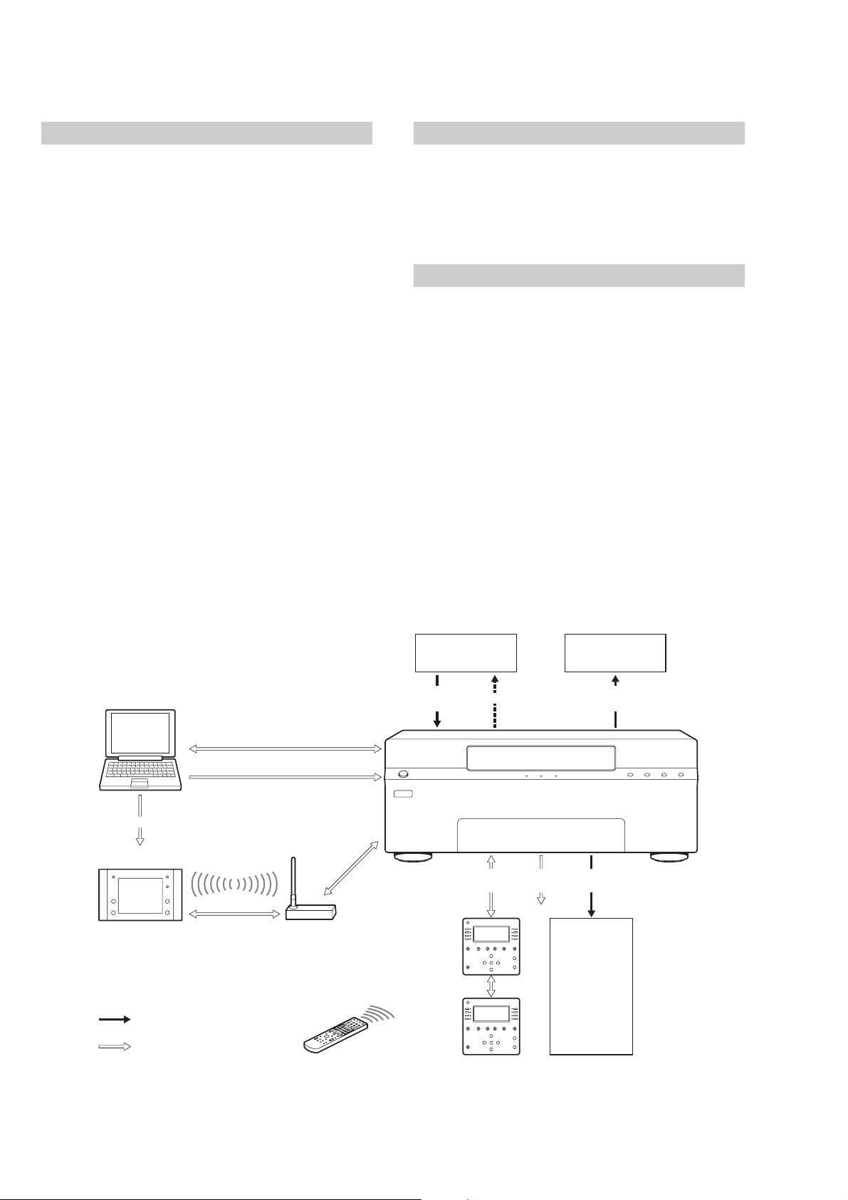
Main Unit
• Zones: Up to six zones receive up to eight source
audio/video signals.
–Preamp Outs: Four fixed outputs for zones 1 to 4,
and two variable outputs for zones 5 and 6.
– Amplification: All six zones have built-in stereo
audio amplifiers at 30 Watts per channel.
–Video outputs for all six zones.
– Keypad connections: RJ45 connectors for all six zones
using CAT5 cables.
• Sources: Up to eight audio/video sources can be
selected by all six zones.
• Remote code entry: Remote code commands can be
learned by the Main Unit.
– on your computer
– on the Main Unit
• 12 V trigger: Six zone-specific 12 V status outputs; each
300 mA max, total 1.2 A.
• RS232C port (Front): Allows you to connect the Main
Unit to your computer to update the settings or
firmware.
• RS232C ports (Rear): Allow you to connect a Sony DVD
Mega Changer (ex. DVP-CX777ES) and a Sony A/V
Receiver (ex. STR-DA5000ES) to the Main Unit.
Keypad
• LCD contrast adjustment.
• Connecting IR IN to an IR emitter enables you to use
the IR Remote Control for the additional range.
• RJ45 connectors enable you to use two Keypads in a
single zone.
RF Remote Control
• LCD panel configurable through your computer.
• Controls the audio/video sources in the main zone and
the other zones.
• Customize touch panels via an RS232C cross cable
connected to your computer.
Computer
Preset Commands
RF Remote Control
: Signal
: Command
RS232C
Preset Commands
RF Antenna
Audio/Video
Signal
Main
Keypad
Subsidiary
Keypad
IR Remote Control
for the Keypad
Audio/Video
Source 1 ~ 8
Serial
RJ45
IR
Zone
Status
Zone 1 – 6
Each input of the
A/V Receiver
Audio/Video
Signal
Audio/Video
Signal
Zone 1 – 6
Display/Signal
4
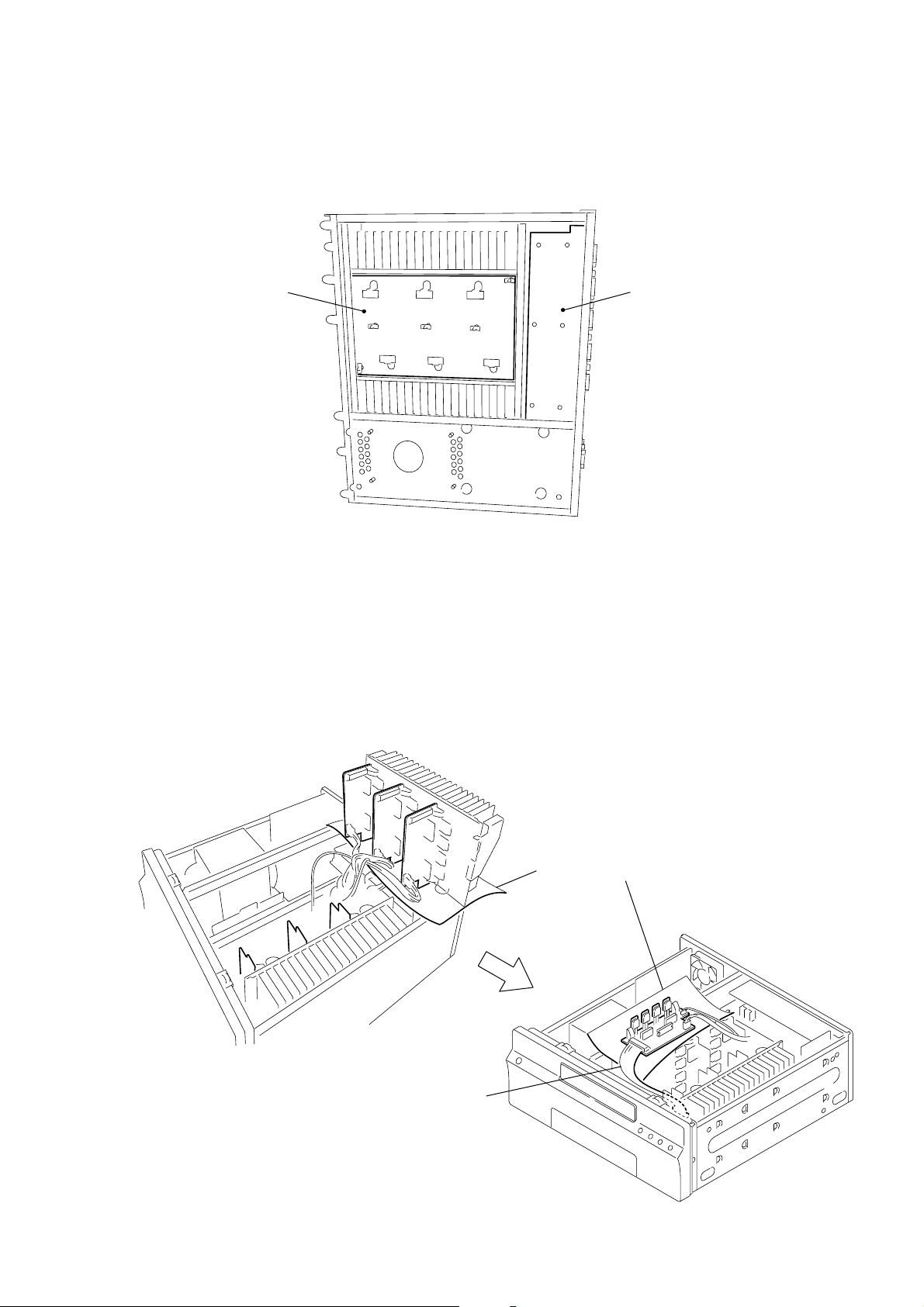
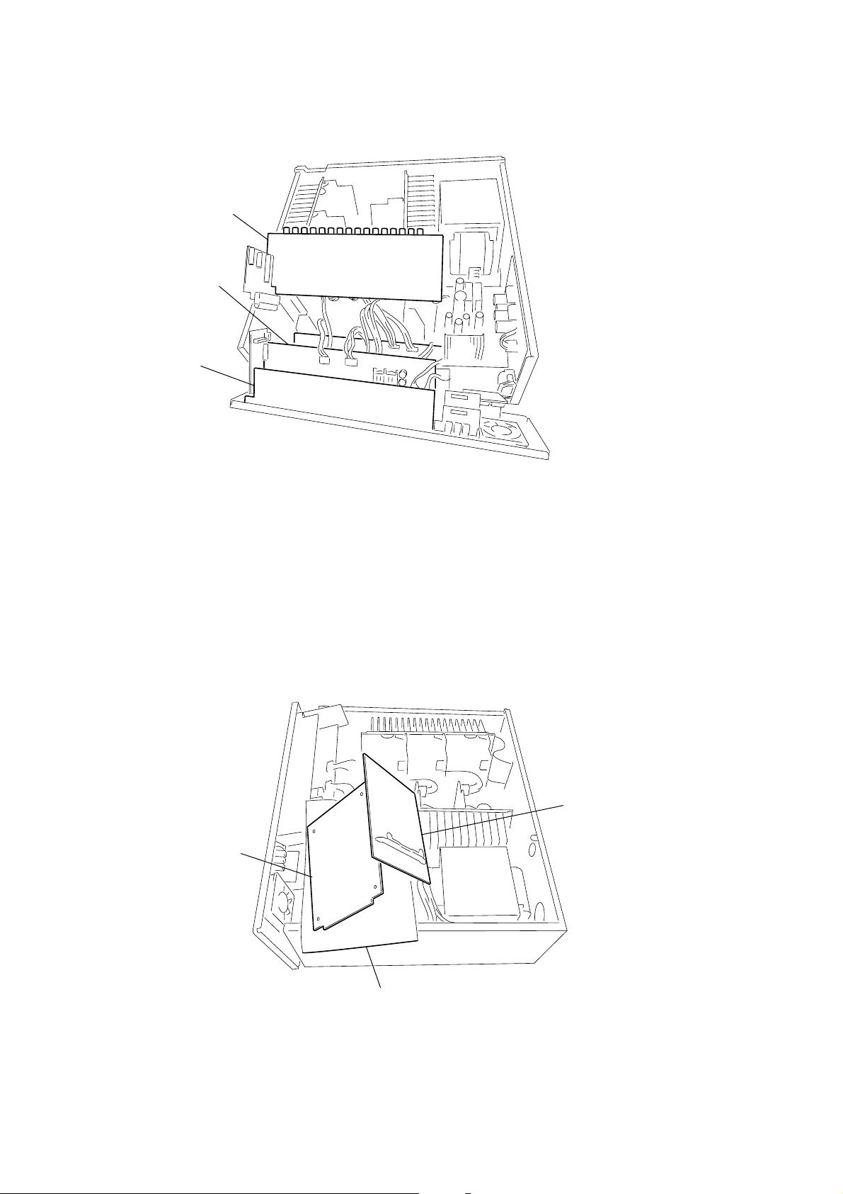
• SERVICE POSITION OF AMP BASE BOARD AND SPEAKER BOARD
2
3
1
4
5
6
Insulated sheet should be used.
The six pieces of the AMP board are used as shown from No. 1 to 6 check only the defective AMP board by
inserting the extension cable.
Extension cable
(J-2501-269-A)(15P)
CAV-M1000ES
AMP BASE board
The AMP BASE board and the SPEAKER board can be checked after the bottom panel is removed from the unit.
• SERVICE POSITION OF AMP BOARD
SPEAKER board
5
CAV-M1000ES
d
• SERVICE POSITION OF BACK PANEL SIDE BOARD
AUDIO I/O BRD board
VIDEO I/O BRD board
IR OUT WB board
Six pieces of the boards are stacked.
• Check the IR OUT WB board and the VIDEO I/O BRD board in the state as shown. To check the portions that are not visible from outside,
remove the two boards together from the back panel and check those portions.
• Check the AUDIO I/O BRD board by removing it independently from the back panel, as shown in the illustration.
• Check the RJ45 board and the PRE OUT BRD board in the same manner as the procedure of checking the AUDIO I/O BRD board.
• Check the SPEAKER board by removing the bottom panel.
• SERVICE POSITION OF AC INLET BOARD
Check the AC INLET board by removing it together with the REGULATOR board from the chassis.
AC INLET boar
REGULATOR board
Insulated sheet should be used.
6
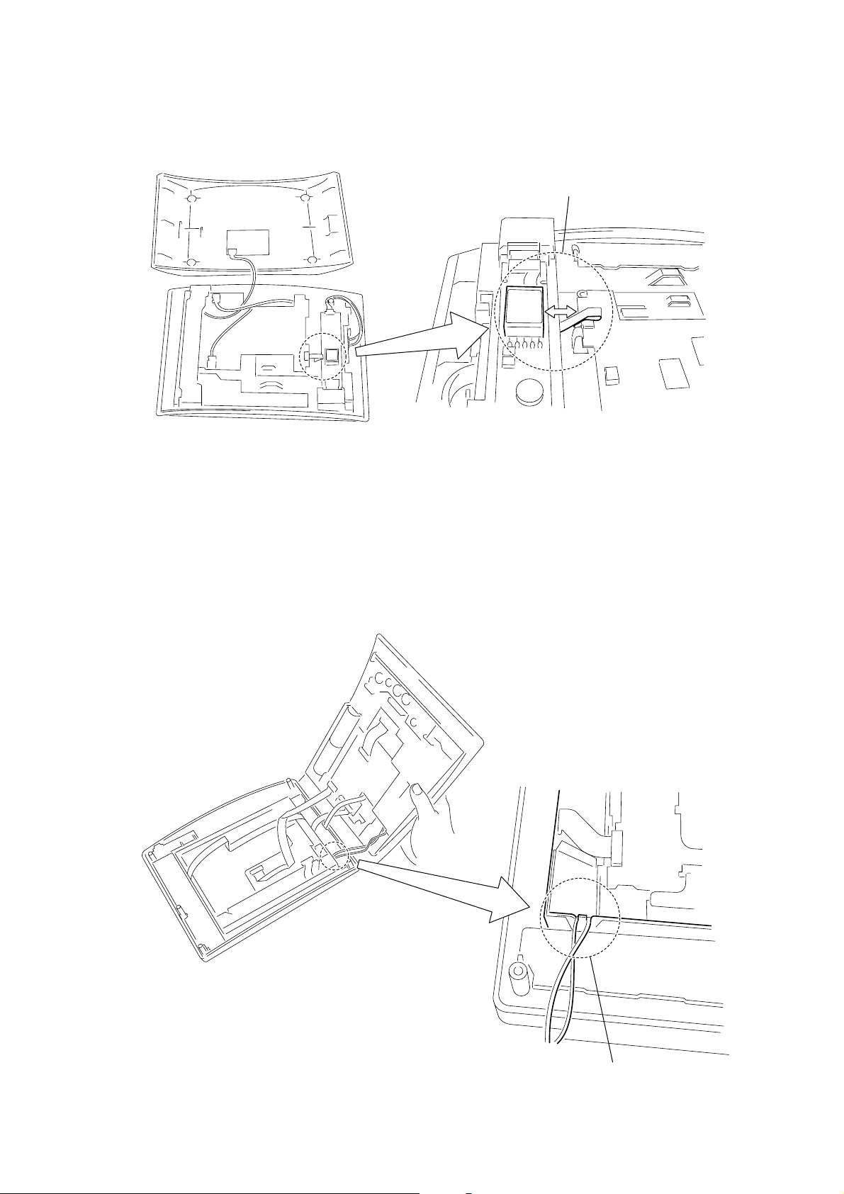
• CAUTIONS ON ASSEMBLING THE COVER
CAV-M1000ES
Be careful that the flexible board should not be brought closer to other parts.
• CAUTIONS ON REPLACING THE LCD BLOCK
Be sure that the LCD harness is kept inserted in the grooves.
7
CAV-M1000ES
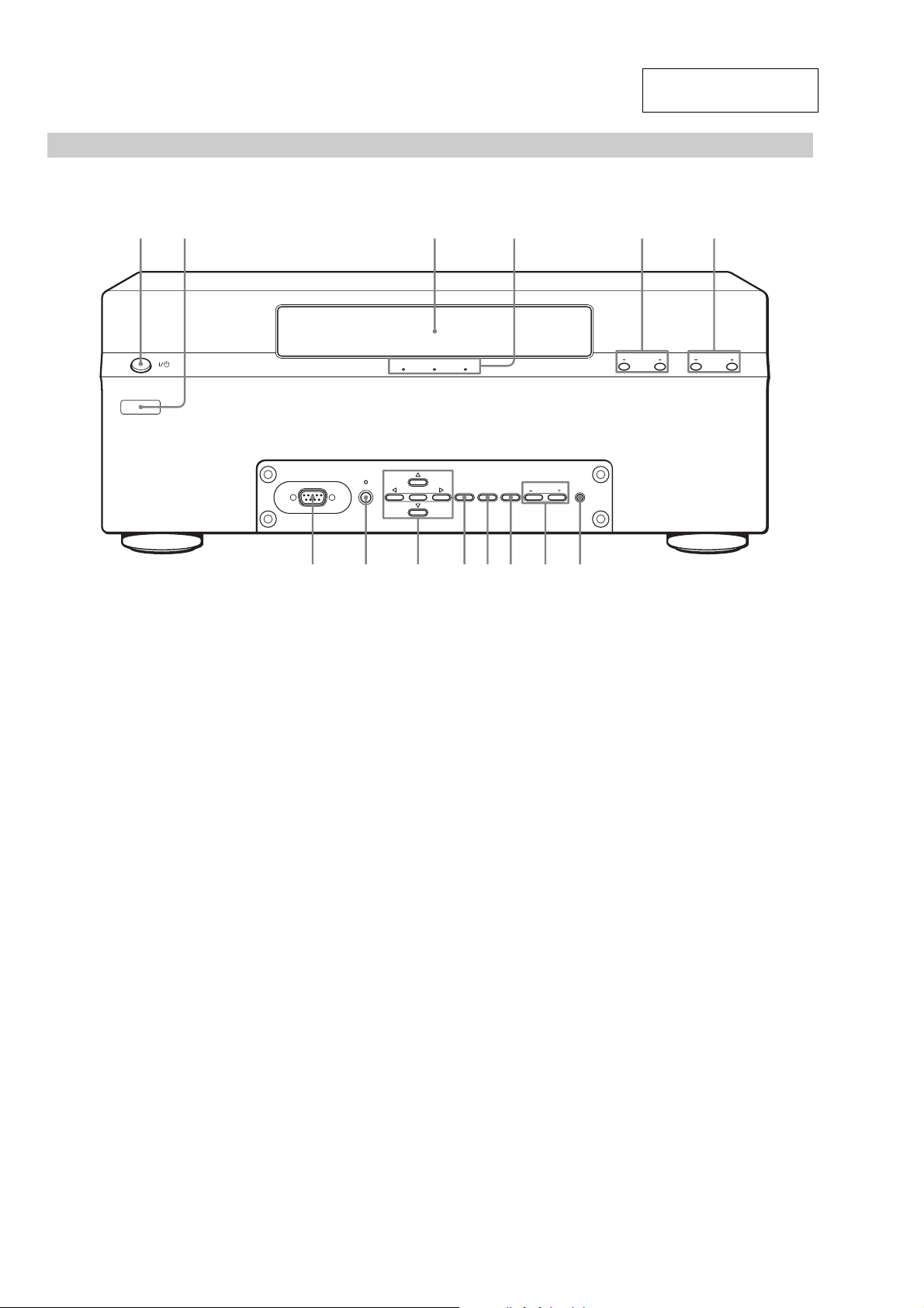
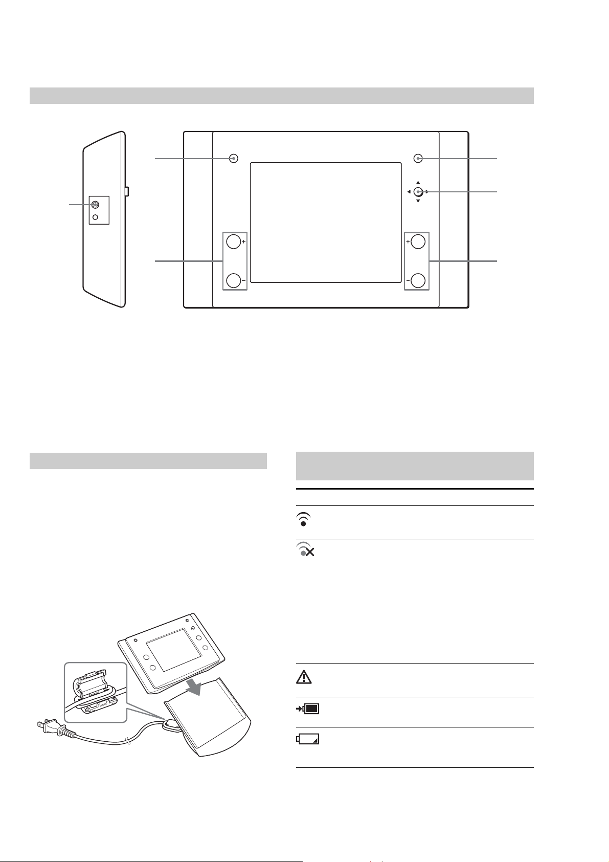
q
q
987
Front panel of the Main Unit
12 3 4 5 6
SECTION 2
GENERAL
This section is extracted
from instruction manual.
1 ?/1 (POWER) switch
Press to turn the power on or off.
RS232C
PROGRAM
CHECK LEARN SETUP
ENTER MODE BA CK CANCEL
;
8 PROGRAM
Press to initiate a firmware update.
ZONE VOLUME
qdqsqa
ALL ZONE
MUTING
f
SOURCE SELECTZONE
2 Learning IR window
Used to input remote codes into the Main Unit.
3 Display window
Displays various information.
4 Mode indicators
Display the current mode. These indicators turn off in
the NORMAL mode.
5 ZONE +/–
Press to select the zone in the NORMAL mode.
6 SOURCE SELECT +/–
Press to select the source component in the NORMAL
mode.
7 RS232C connector
Used to update the firmware of the Main Unit and to
upload/download setup data from a computer using
an RS232C cross cable.
9 Cursor/ENTER
Press to select a menu.
q; MODE
Press repeatedly to select the mode.
qa BACK
Press to return to the previous layer of the menu.
qs CANCEL
Press to cancel the present operation and return to the
NORMAL mode.
qd ZONE VOLUME +/–
Press to adjust the volume of the selected zone.
qf ALL ZONE MUTING
Press to set muting on or off in all zones.
8
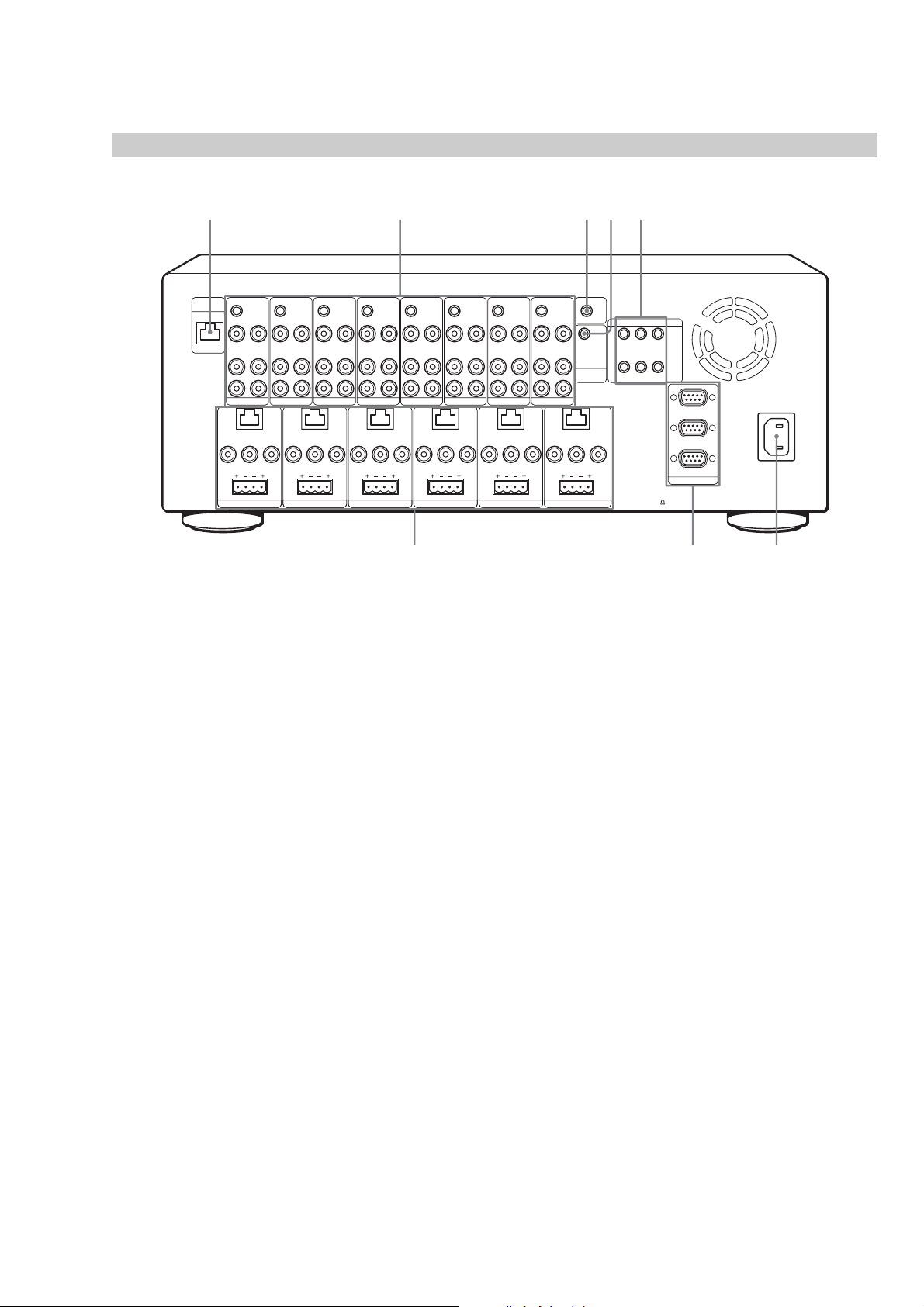
Rear panel of the Main Unit
q
q
qjqkq
CAV-M1000ES
g
ANTENNA
IR OUT
VIDEO OUT
VIDEO IN
AUDIO OUT
AUDIO IN
L
R
SOURCE 1
KEYPAD
LR
FIXED
VIDEO OUT
PRE OUT
RL
SPEAKERS (CLASS 2 WIRING
ZONE 1
IR OUT
VIDEO OUT
VIDEO IN
AUDIO OUT
AUDIO IN
L
R
SOURCE 2
FIXED
PRE OUT
)
SPEAKERS (CLASS 2 WIRING
IR OUT
VIDEO IN
AUDIO IN
L
R
SOURCE 3
KEYPAD
LR
VIDEO OUT
RL
ZONE 2
VIDEO OUT
AUDIO OUT
)
IR OUT
VIDEO OUT
VIDEO IN
AUDIO OUT
AUDIO IN
L
R
SOURCE 4
KEYPAD
LR
FIXED
VIDEO OUT
PRE OUT
RL
SPEAKERS (CLASS 2 WIRING
ZONE 3
h
IR OUT
VIDEO OUT
VIDEO IN
AUDIO OUT
AUDIO IN
L
R
SOURCE 5
)
SPEAKERS (CLASS 2 WIRING
IR OUT
VIDEO IN
AUDIO IN
SOURCE 6
KEYPAD
LR
FIXED
PRE OUT
RL
ZONE 4
IR OUT IR OUT
VIDEO OUT
VIDEO OUT
VIDEO IN
AUDIO OUT
AUDIO OUT
AUDIO IN
L
L
R
R
SOURCE 7
KEYPAD
LR
VARIABLE
VIDEO OUT
PRE OUT
RL
)
SPEAKERS (CLASS 2 WIRING
ZONE 5
IR OUT
VIDEO IN
AUDIO IN
SOURCE 8
VIDEO OUT
)
COMMON
VIDEO OUT
AUDIO OUT
L
CONTROL
A1 II
R
KEYPAD
LR
VARIABLE
VIDEO OUT
PRE OUT
RL
SPEAKERS (CLASS 2 WIRING
ZONE 6
12V TRIGGER
123
456
SPEAKERS IMPEDANCE
)
USE 4-16
l
STR
DVP
AUX
RS232C
~AC IN
w; wa ws
qg ANTENNA (page 18)
Hooks up to the RF Antenna using a shielded CAT5
cable, to operate the RF Remote Control.
qh SOURCE connection jacks
a) IR OUT (page 17)
A 3.5 mm monaural mini jack for the connection of an
IR emitter to control the eight source components
individually. IR signals received from a zone will be
routed to the IR sensor of the source component.
b) VIDEO IN (page 17)
An RCA jack for composite video input from a source
component.
c) VIDEO OUT (page 18)
An RCA jack for connecting a video source to another
local component.
Note
This is a buffered video connection, and this loop-through is
active even when the Main Unit is turned off, as long as the
AC power cord is plugged in.
d) AUDIO IN (page 17)
RCA jacks for stereo line level audio input from a
source component.
e) AUDIO OUT (page 18)
RCA jacks for connecting an audio source to another
local component.
Note
This is a buffered audio connection, and this loop-through is
active even when the Main Unit is turned off, as long as the
AC power cord is plugged in.
qj IR OUT COMMON (page 18)
A 3.5 mm monaural mini jack for the connection of an
IR emitter to control any IR-controlled component
such as a lighting system or motorized screen.
qk CONTROL A1II (page 17)
Hooks up to a Sony CD Mega Changer (ex. CDPCX455) equipped with a matching jack allowing the
Main Unit to control the source component.
ql 12 V TRIGGER (page 18)
Provide control outputs of +12 V DC that turn devices
on and off in sync with the zone to drive voltage
sensing relay modules and AC strips.
9
CAV-M1000ES
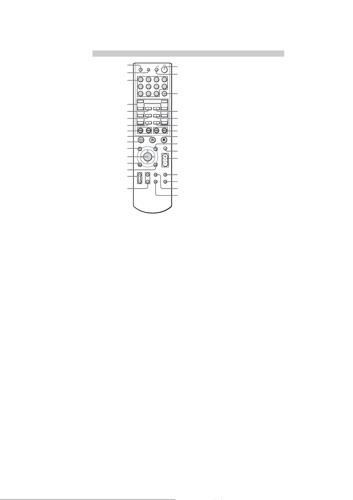
RF Remote Control
6
1 MUTING
Press to mute the audio.
2 VOLUME +/–
Press to adjust the volume.
3 SYSTEM OFF
Press to shut down the system.
1
MUTING
VOLUME
SYSTEM OFF
CHANNEL
4 Cursor/ENTER
Press to control the source.
5 CHANNEL +/–
Press to control the source.
6 RS232C connector
Hook up a computer using the dedicated RS232C
cable.
3
4
52
Charging the internal battery
1
Attach the supplied ferrite core to the AC power
cord of the charger cradle, then wrap the AC
power cord twice around the ferrite core.
2
Connect the AC power cord of the charger cradle to
the wall outlet.
3
Place the RF Remote Control on the charger cradle.
The internal battery starts charging. It takes
approximately 16 hours for full charging. Charge for
considerable time when you use it for the first time.
3
12
To the wall outlet
Meaning of icons shown on the top of the
display window
Icon Meaning
Communication between the RF Remote Control and
the Main Unit is completed.
Communication between the RF Remote Control and
the Main Unit has been interfered with. Or the distance
from the RF Remote Control to the RF Antenna is way
too far.
c Place the RF Antenna closer to the RF Remote
Control.
c Avoid interference of metal objects such as a cabinet
between the RF Antenna and the RF Remote Control.
Other radio waves have been interfering.
c Move the RF Remote Control about 1 inch to the left
to the right or up or down. Doing so may solve the
problem.
Some kind of trouble has occurred.
Contact your nearest Sony dealer.
The internal battery is being charged on the charger
cradle.
The remaining power of the battery is low.
c Charge the battery by placing the RF Remote Control
on the charger cradle.
10
IR Remote Control for Keypads
1
SLEEP DIMMER
2
1234
3
5678
90
4
5
6
SELECT
LOCK DISC
PAGE SOURCE
DOWN
7
8
9
q;
TOP MENU/
GUIDE
qa
qs
qd
qf
*
qg
*
qh
RETURN/EXITDISPLAY
TV VOL TV CH FOLDER F1
TV/VIDEO F2
TV
>10
ENTER
UP
MENU MUTING
VOLUME
qj
qk
ql
w;
wa
ws
wd
wf
wg
wh
wj
wk
wl
e;
ea
CAV-M1000ES
*
*
* Only a Sony TV monitor can be controlled with these buttons.
Buttons marked in gray are used to control the source
components.
1 SLEEP
Press to activate the sleep function that turns off the
Keypad automatically after the specified duration.
The time changes as shown below.
2:00 t1:30 t1:00 t0:30 tOFF
2 DIMMER
Press repeatedly to change the brightness of the LCD
backlight.
3 Numeral
Press to select a number, representing, for example, a
desired track of the source.
4 SELECT
Press to select a menu on the display on the LCD, such
as a source menu, a disc title list, etc.
5 LOCK
Press to lock the selected source.
6 PAGE
Press to return to the previous menu or to view the
current status of the disc title list or the preset station
list. If there is no list, only a source name will be
displayed.
7 DOWN
Press to scroll the LCD menu down.
8 ./>
Press to locate a specific track of the source or to select
a preset station.
9 X (PAUSE)
Press to pause the playback of the source.
q; N (PLAY)
Press to operate the selected source.
qa TOP MENU/GUIDE
Press to display the top menu while using a source
component such as a DVD player.
qs CURSOR/ENTER
Press to select a menu while using a source component
such as a DVD player.
qd DISPLAY
Press to display on-screen messages from equipment
such as a DVD player.
You cannot control commands, such as PROGRAM,
SHUFFLE, REPEAT and A-B REPEAT of the DVD
Mega Changer that appear on the display when you
press DISPLAY.
qf RETURN/EXIT
Press to return to the previous menu screen (level) or
to quit the menu function while using a source
component such as a DVD player.
qg TV VOL +/–
Press to adjust the Sony TV volume.
qh TV CH +/–
Press to change the Sony TV channel.
qj ?/1 switch
Press to turn the Keypad on/off.
qk TV ?/1 switch
Press to turn the Sony TV on/off.
ql ENTER
Press to confirm the selection.
w; DISC
Press to select a disc of a DVD/CD Mega Changer.
wa SOURCE
Press to return to the source components list screen.
ws UP
Press to scroll the LCD menu up.
wd m/M
Press to locate a portion you want to play within a
track of the source.
wf x (STOP)
Press to stop the current playback.
wg MENU
Press to display a menu while using a source
component such as a DVD player.
wh MUTING
Press to mute the speaker output in a zone.
wj VOLUME +/–
Press to adjust the volume in a zone.
wk F1
A button reserved for source components.
wl F2
A button reserved for source components.
e; FOLDER
Press to move to the FOLDER screen while using a
DVD player.
ea TV/VIDEO
Press to switch signals between TV input and Video
input of the Sony TV monitor.
11
CAV-M1000ES
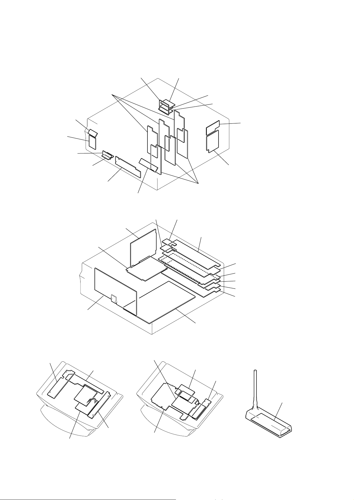
d
• Circuit Board Location
SECTION 3
DIAGRAMS
PW SW board
LEARNING board
RS232F SUB board
REGULATOR board
RS232B SUB board
AMP board
RS232F board
FUNCTION KEY board
AC INLET board
SOURCE KEY board
12V BOTTOM board
RS232B TOP board
RS232B board
RS232B BOTTOM board
CZ CONNECTOR board
CONNECTOR board
AMP board
12V TRIGGER board
IR OUT WB board
DISPLAY board
L KEY board
CHARGER CRADLE UNIT
RF board
R KEY board
VIDEO I/O BRD board
AUDIO I/O BRD board
RJ 45 board
PRE OUT BRD board
SPEAKER board
AMP BASE board
TRANSLATION board
POWER board
INVERTER UNIT
RF ANTENNA boar
PA UNIT
12
CAV-M1000ES
THIS NOTE IS COMMON FOR PRINTED WIRING BOARDS AND SCHEMATIC DIAGRAMS.
(In addition to this, the necessary note is printed in each block.)
For Schematic Diagrams.
Note:
• All capacitors are in µF unless otherwise noted. (p: pF)
50 WV or less are not indicated except f or electrolytics and
tantalums.
• All resistors are in Ω and 1/
specified.
• % : indicates tolerance.
• f : internal component.
• 2 : nonflammable resistor.
• 5 : fusible resistor.
• C : panel designation.
Note: The components identified by mark 0 or dotted
line with mark 0 are critical for safety.
Replace only with part number specified.
• A : B+ Line.
• B : B- Line.
•Voltages and w av ef orms are dc with respect to ground under no-signal (detuned) conditions.
No mark: POWER ON
* : Imposible to measure
•Voltages are taken with a VOM (Input impedance 10 MΩ).
Voltage variations may be noted due to normal production
tolerances.
•Waveforms are taken with a oscilloscope.
• Circled numbers refer to waveforms.
• Signal path.
F : AUDIO
L : VIDEO
4
W or less unless otherwise
For Printed Wiring Boards.
Note:
• X : parts extracted from the component side.
• a : Through hole.
• f : internal component.
• : Pattern from the side which enables seeing.
C
Q
B
E
B
Caution:
Pattern face side: Parts on the pattern face side seen from
(Side A) the pattern face are indicated.
Parts face side: Parts on the parts face side seen from
(Side B) the parts face are indicated.
These are omitted.
CE
These are omitted.
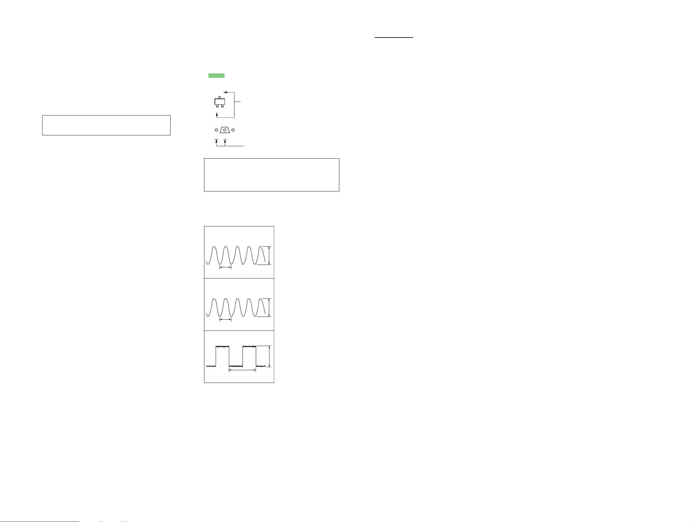
•Waveforms
– DISPLAY BOARD –
MEMO
1
IC500 tk (XO)
(at the point of C626)
60.5ns
1V/DIV, 40ns/DIV
2
IC600 qd (XOUT)
(at the point of C626)
124.6ns
1V/DIV, 100ns/DIV
3
IC400 6 (XOUT)
1V/DIV, 1µs/DIV
2.07
µ
s
3.7Vp-p
3.9Vp-p
3.2Vp-p
CAV-M1000ES
1313
CAV-M1000ES
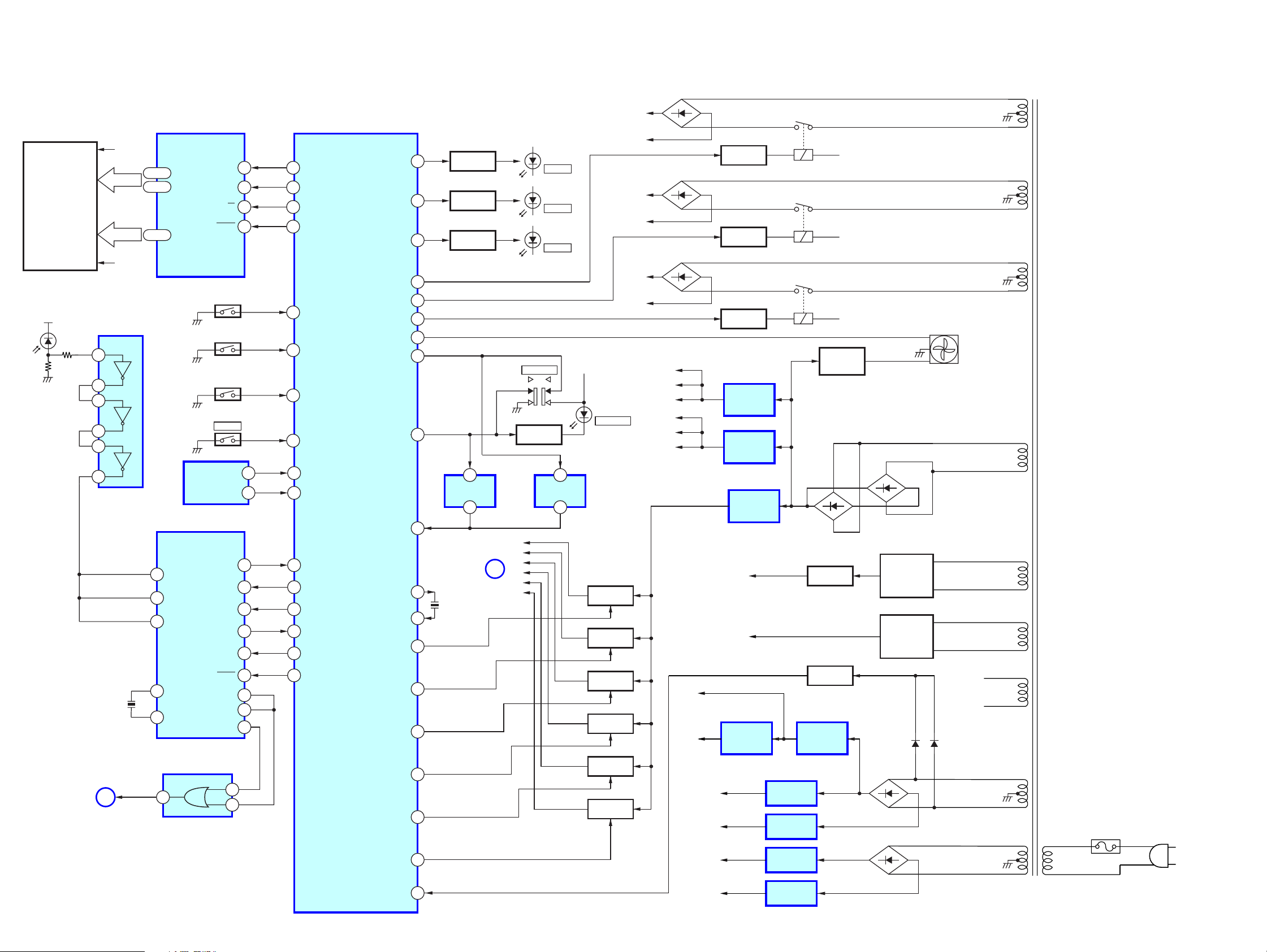
3-1. BLOCK DIAGRAM — MAIN/POWER SECTION —
Z56 +B
D853
T901
POWER TRANSFORMER
FL400
LIQUID CRYSTAL
DISPLAY
+3.3V
D600
(learning IR)
INVERTER
1
2
3
4
5
F1
F2
IC602
45 - 19
17 - 9
63 - 48
IC400
FL DISPLAY DRIVE
SEG 0 - 35
GRID 0 - 15
S720 - 725
S700 - 703
S710 - 714
SYSTEM CONTROLLOR
4 41
SGATA FL DAT
3 40
SCK FL CLK
2 42
CS FL LAT
1 43
RESET FL CLR
132
AD1
133
AD2
134
AD3
S141
POWER
61
PW ON/OFF
IC500 (1/5)
LED2
LED3
LED4
AMP RYC
AMP RYB
AMP RYA
FAN
MD0
MD2
119
120
121
Z56 -B
Q403
LED DRIVE
Q404
LED DRIVE
Q405
LED DRIVE
93
92
91
34
54
52
SW500
PROGRAM
Q507
LED DRIVE
D400
CHECK
D403
LEARN
D405
SETUP
+3.3V
D512
PROGRAM
Z34 +B
Z34 -B
Z12 +B
Z12 -B
D852
D851
KP 12V 1
KP 12V 2
KP 12V 3
KP 12V 4
KP 12V 5
KP 12V 6
Q830
RELAY DRIVE
Q820
RELAY DRIVE
Q810
RELAY DRIVE
IC801
+12V REG
IC802
+12V REG
RY831
RY821
RY811
Q801
FAN
DRIVE
RY+12V
RY+12V
RY+12V
FAN
IR OUT/RS232C/
12V TRIGGER
SECTION
6 100
6
EEPROM
IC600
REMOTE CONTROL DRIVE
20
INTO
19
INTI
29
TARM
13
XOUT
15
XIN
IC601
NOR GATE
4
A
X600
8MHz
IROUT
SCL EEPROM,SCL
IC509
5 99
SDA EEPROM,SDA
88 116
P00 REM RM REM
P01 WAKEUP RM WAIT
P15 WAKEUP RM WAKEUP
87 115
75 114
36 87
RxDo P62 RM RX
35 85
TxDo P63 RM TX
12
RESET NC
7
TBOIN
28
TBIOUT
22
P00
1
2
84
PSTX
12VTRIG 1
12VTRIG 2
12VTRIG 3
12VTRIG 4
12VTRIG 5
12VTRIG 6
55
58
XO
57
XI
45
46
47
48
49
50
2
IC510
RESET
1
IR OUT/RS232C/
12V TRIGGER
SECTION
X500
16.5MHz
12V 1
12V 2
12V 3
B
12V 4
12V 5
12V 6
2
IC511
RESET
1
Q812,814
SWITCH
Q822,824
SWITCH
Q832,834
SWITCH
Q842,844
SWITCH
Q852,854
SWITCH
Q862,864
SWITCH
+5V
+3.3V
+5V
(VIDEO I/O)
-5V
(VIDEO I/O)
+15V
(AUDIO I/O)
IC820
+12V REG
-32V
RY12V
IC851
+3.3V REG
IC2500
+5V REG
IC2600
-5V REG
IC1001
+15V REG
D862
-32V REQ
SWITCH
IC850
+5V REG
Q802
Q803
D872
D813,814
D803,804
RECT
D823,824
D833,834
RECT
D805
D863
D864
D806
F1
F2
F900
AC
IN
CAV-M1000ES
VOL DETECT STOP
60
-15V
(AUDIO I/O)
IC1002
-15V REG
1414
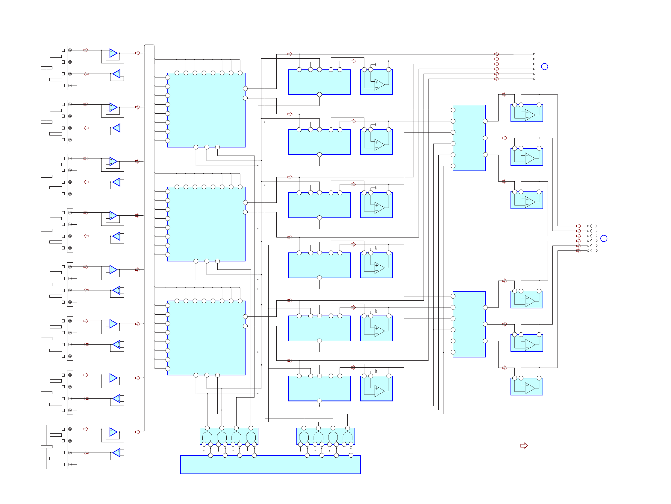
3-2. BLOCK DIAGRAM — AUDIO I/O SECTION —
CAV-M1000ES
SOURCE 1
SOURCE 2
SOURCE 3
SOURCE 4
SOURCE 5
SOURCE 6
SOURCE 7
AUDIO IN
AUDIO OUT
AUDIO IN
AUDIO OUT
AUDIO IN
AUDIO OUT
AUDIO IN
AUDIO OUT
AUDIO IN
AUDIO OUT
AUDIO IN
AUDIO OUT
AUDIO IN
AUDIO OUT
J1010
L
R-CH
R
L
R-CH
R
J1020
L
R-CH
R
L
R
R-CH
J1030
L
R-CH
R
L
R
R-CH
J1040
L
R-CH
R
L
R-CH
R
J1050
L
R-CH
R
L
R-CH
R
J1060
L
R-CH
R
L
R-CH
R
J1070
L
R-CH
R
L
R
R-CH
IC1010
BUFFER
5
6
IC1011
BUFFER
7
5
6
IC1021
BUFFER
7
5
6
IC1031
BUFFER
7
5
6
IC1041
BUFFER
7
5
6
IC1051
BUFFER
7
5
6
IC1061
BUFFER
7
5
6
IC1071
BUFFER
7
IC1020
BUFFER
IC1030
BUFFER
IC1040
BUFFER
IC1050
BUFFER
IC1060
BUFFER
IC1070
BUFFER
L1
7
26
17 6 5 7
16
23
BASS-COM
23
BASS-COM
23
BASS-COM
23
BASS-COM
23
BASS-COM
23
BASS-COM
19
TONE-OUT
19
TONE-OUT
19
TONE-OUT
19
TONE-OUT
19
TONE-OUT
19
TONE-OUT
IC1101
BUFFER
IC1201
BUFFER
IC1301
BUFFER
IC1401
BUFFER
IC1501
BUFFER
IC1601
BUFFER
IC1800
QUAD DRIVER
26
INA
22
INB
19
INC
14
CK
15
DATA
16
STB
IC1900
QUAD DRIVER
26
INA
22
INB
19
INC
14
CK
15
DATA
16
STB
OUTA
OUTB
OUTC
OUTA
OUTB
OUTC
25
23
18
25
23
18
5 6 7
5 6 7
5 6 7
5 6 7
5 6 7
5 6 7
5
6
L2
7
5
6
L3
7
5
6
L4
7
5
6
L5
7
5
6
L6
7
5
6
L7
7
5
6
L1
41
S1
S137S236S335S434S533S632S731S8
L2
42
S2
L3
43
S3
L4
44
S4
L5
1
S5
L6
2
S6
L7
3
S7
L8
4
S8
L1
41
S1
S137S236S335S434S533S632S731S8
L2
42
S2
L3
43
S3
L4
44
S4
L5
1
S5
L6
2
S6
L7
3
S7
L8
4
S8
L1
41
S1
S137S236S335S434S533S632S731S8
L2
42
S2
L3
43
S3
L4
44
S4
L5
1
S5
L6
2
S6
L7
3
S7
L8
4
S8
IC1700
SWITCH CONNECTION
CK16DATA18STB
IC1701
SWITCH CONNECTION
CK16DATA18STB
IC1702
SWITCH CONNECTION
CK16DATA18STB
19
19
19
30
5
S9
29
S9
30
5
S9
29
S9
30
5
S9
29
S9
STB
TONE-IN
26
TONE-IN
26
TONE-IN
26
TONE-IN
26
TONE-IN
26
TONE-IN
DATA
IC1100
ELECTRONIC TONE CONTROL
CK
13
17 6 5 7
16
STB
DATA
IC1200
ELECTRONIC TONE CONTROL
CK
13
17 6 5 7
16
STB
DATA
IC1300
ELECTRONIC TONE CONTROL
CK
13
17 6 5 7
16
STB
DATA
IC1400
ELECTRONIC TONE CONTROL
CK
13
17 6 5 7
16
STB
DATA
IC1500
ELECTRONIC TONE CONTROL
CK
13
17 6 5 7
16
STB
DATA
IC1600
ELECTRONIC TONE CONTROL
CK
13
IC1102
BUFFER
IC1202
BUFFER
IC1302
BUFFER
IC1402
BUFFER
IC1502
BUFFER
IC1602
BUFFER
L1
L2
L3
AMP/SPEAKER/
PRE OUT
D
L4
SECTION
L5
L6
L1
L2
L3
AMP/SPEAKER/
PRE OUT
C
L4
L5
L6
SECTION
AUDIO IN
SOURCE 8
AUDIO OUT
CAV-M1000ES
J1080
L
R-CH
R
L
R
R-CH
IC1080
BUFFER
5
6
IC1081
BUFFER
7
L8
7
5
6
IC500 (5/5)
SYSTEM CONTROLLOR
6
IC502
BUFFER
4 531 2810 91113 12
VCC VCC
1
AUDIO CLK
2
AUDIO DAT
4
AUDIO STB13AUDIO STB2
6
IC503
BUFFER
4 531 2810 91113 12
AUDIO STB337AUDIO STB437AUDIO STB537AUDIO STB6
• R-CH is omitted due to same as L-CH.
• Signal Path
: AUDIO
37
1515

CAV-M1000ES
3-3. BLOCK DIAGRAM — VIDEO I/O SECTION —
SOURCE 1
SOURCE 2
SOURCE 3
SOURCE 4
SOURCE 5
SOURCE 6
SOURCE 7
SOURCE 8
VIDEO IN
VIDEO OUT
VIDEO IN
VIDEO OUT
VIDEO IN
VIDEO OUT
VIDEO IN
VIDEO OUT
VIDEO IN
VIDEO OUT
VIDEO IN
VIDEO OUT
VIDEO IN
VIDEO OUT
VIDEO IN
VIDEO OUT
J2001
J2002
J2003
J2004
J2005
J2006
J2007
J2008
IC2000
QUAD VIDEO DRIVER
1
OUT1
13
OUT2
12
OUT3
11
OUT4
IC2001
QUAD VIDEO DRIVER
1
OUT1
13
OUT2
12
OUT3
11
OUT4
17
IN1
3
IN2
6
IN3
9
IN4
17
IN1
3
IN2
6
IN3
9
IN4
Q2010
BUFFER
Q2020
BUFFER
Q2030
BUFFER
Q2040
BUFFER
Q2050
BUFFER
Q2060
BUFFER
Q2070
BUFFER
Q2080
BUFFER
IC2210
ANALOG MULTIPLEX
13
0
14
1
15
2
12
3
1
4
5
5
2
6
4
7
IC2220
ANALOG MULTIPLEX
13
0
14
1
15
2
12
3
1
4
5
5
2
6
4
7
IC2230
ANALOG MULTIPLEX
13
0
14
1
15
2
12
3
1
4
5
5
2
6
4
7
IC2240
ANALOG MULTIPLEX
13
0
14
1
15
2
12
3
1
4
5
5
2
6
4
7
IC2250
ANALOG MULTIPLEX
13
0
14
1
15
2
12
3
1
4
5
5
2
6
4
7
IC2260
ANALOG MULTIPLEX
13
0
14
1
15
2
12
3
1
4
5
5
2
6
4
7
IC2100
SERIAL PARALLEL CONVERTER
11
A
10
B
9
C
6
INH
3
COM
11
A
10
B
9
C
6
INH
3
COM
11
A
10
B
9
C
6
INH
3
COM
11
A
10
B
9
C
6
INH
3
COM
11
A
10
B
9
C
6
INH
3
COM
11
A
10
B
9
C
6
INH
3
COM
5
P1
6
P2
7
P3
8
P4
9
P5
10
P6
11
P7
12
P8
13
P9
14
P10
15
P11
16
P12
2
CLK
4
DATA
30
STB
31
CLB
13
12
11
10
9
8
20
CNT1
17
IN1
19
CNT1
3
IN2
20
CNT1
17
IN1
19
CNT1
3
IN2
20
CNT1
17
IN1
19
CNT1
3
IN2
IC2300
INVERTER
IC2400
QUAD VIDEO DRIVER
IC2410
QUAD VIDEO DRIVER
IC2420
QUAD VIDEO DRIVER
28
P24
27
P23
26
P22
25
P21
24
P20
23
P19
22
P18
21
P17
20
P16
19
P15
18
P14
17
P13
1
2
3
4
5
6
1
OUT1
2
OUT2
VIDEO 01
1
OUT1
2
OUT2
1
OUT1
2
OUT2
VIDEO 02
VIDEO 03
VIDEO 04
VIDEO 05
VIDEO 06
E
AMP/SPEAKER/
PRE OUT
SECTION
1
8
6
3
8
11
IC505
BUFFER
IC505
BUFFER
IC504
BUFFER
IC504
BUFFER
IC504
BUFFER
IC504
BUFFER
12
13
+5V
9
10
+5V
5
4
+5V
2
1
+5V
9
10
+5V
12
13
+5V
IC3600
DIFFERENTIAL
BUS TRASCEIVER
IC3610
DIFFERENTIAL
BUS TRASCEIVER
IC3500
DIFFERENTIAL
BUS TRASCEIVER
IC3510
DIFFERENTIAL
BUS TRASCEIVER
IC3400
DIFFERENTIAL
BUS TRASCEIVER
IC3410
DIFFERENTIAL
BUS TRASCEIVER
IC3300
DIFFERENTIAL
BUS TRASCEIVER
IC3310
DIFFERENTIAL
BUS TRASCEIVER
IC3200
DIFFERENTIAL
BUS TRASCEIVER
IC3210
DIFFERENTIAL
BUS TRASCEIVER
IC3100
DIFFERENTIAL
BUS TRASCEIVER
IC3110
DIFFERENTIAL
BUS TRASCEIVER
CN3600
TX+
6
A
4
DI
7
B
7
B
1
RO
6
A
6
A
4
DI
7
B
7
B
1
RO
6
A
6
A
4
DI
7
B
7
B
1
RO
6
A
6
A
4
DI
7
B
7
B
1
RO
6
A
6
A
4
DI
7
B
7
B
1
RO
6
A
6
A
4
DI
7
B
7
B
1
RO
6
A
1
TX+
2
3
IR RET
4
ZONE 6
IR
KEYPAD
5
+12V
6
7
8
CN3500
TX+
1
TX+
2
3
IR RET
4
ZONE 5
IR
5
IR RET
IR RET
IR RET
IR RET
KEYPAD
6
7
8
CN3400
TX+
1
TX+
2
3
ZONE 4
4
IR
KEYPAD
5
6
7
8
CN3300
TX+
1
TX+
2
3
ZONE 3
4
IR
KEYPAD
5
6
7
8
CN3200
TX+
1
TX+
2
3
ZONE 2
4
IR
KEYPAD
5
6
7
8
CN3100
TX+
1
TX+
2
3
ZONE 1
4
IR
KEYPAD
5
6
7
8
+12V
+12V
+12V
+12V
+12V
CAV-M1000ES
• R-CH is omitted due to same as L-CH.
• Signal Path
: VIDEO
IC500 (4/5)
SYSTEM CONTROLLOR
IC501
BUFFER
9 10
16
VIDEO CLK
6
3
11
8
5 4
2 1
12 13
+5V
83
67
82
66
81
65
80
64
79
63
78
IR 3 IN
CATS 2 TX
IR 2 IN
CATS 1 TX
62
IR 1 IN
17
18
19
IR 6 IN
IR 5 IN
CATS 5 TX
CATS 4 TX
IR 4 IN
CATS 3 TX
VIDEO STB
VIDEO DAT
VIDEO CLR
CATS 6 TX
1616
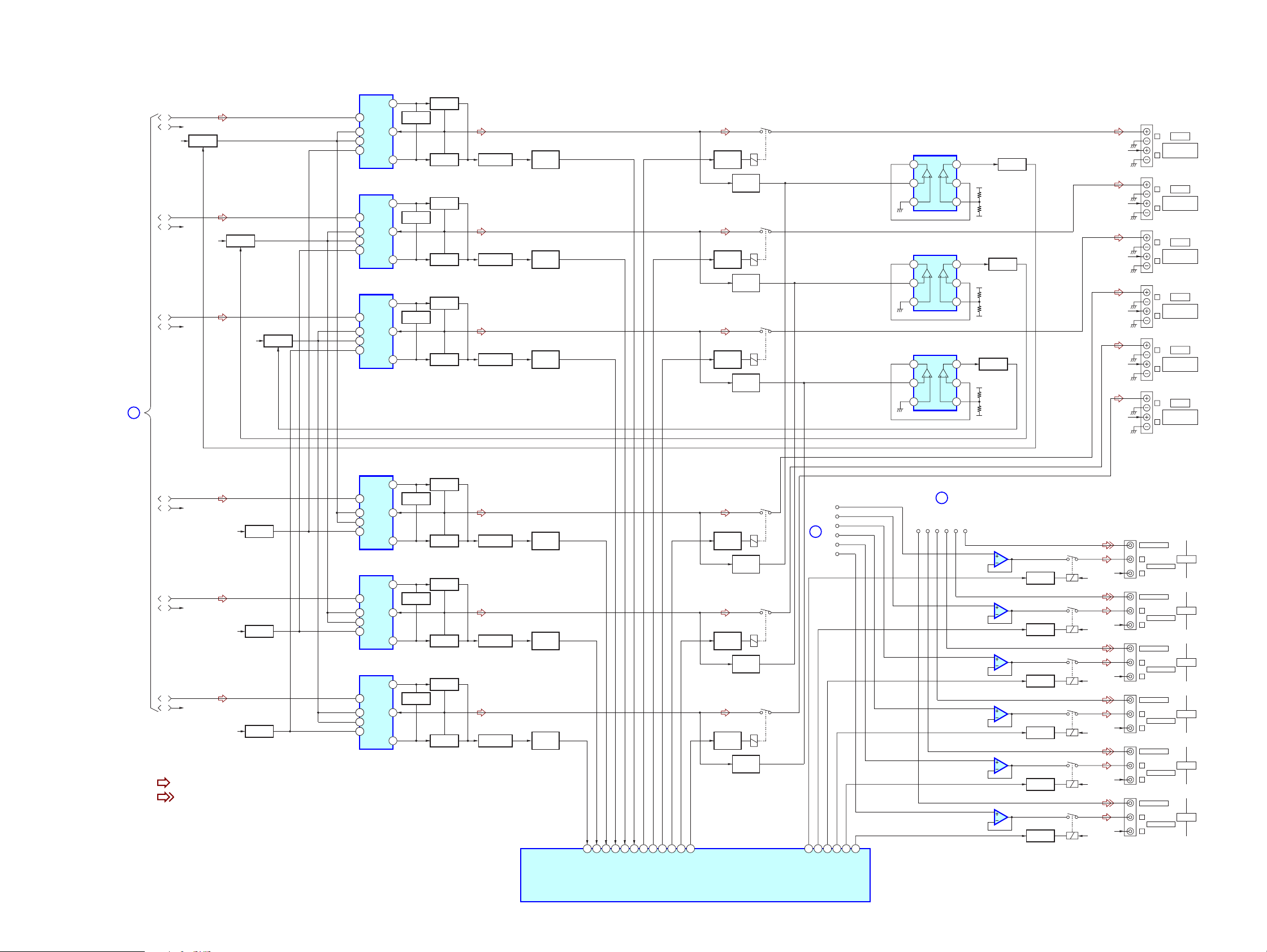
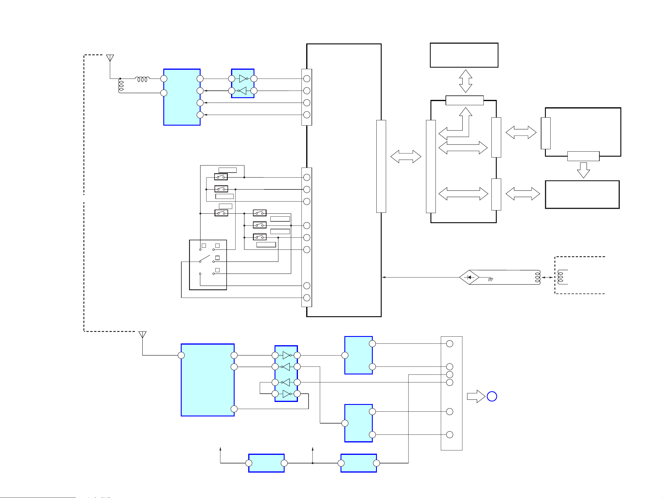
3-4. BLOCK DIAGRAM — AMP/SPEAKER/PRE OUT SECTION —
IC100
POWER AMP
12
C
AUDIO I/O
SECTION
L1
R1 R-CH
Z12+B
L2
R2
L3
R3
+V OUT2
IN28
8
VCC
8
Q811,850
SWITCH
R-CH
Q821,851
Z34+B
SWITCH
R-CH
Q831,853
Z56+B
SWITCH
13
8
14
8
15
8
8
13
8
14
8
15
8
8
13
8
14
8
15
VCC
VEE
-V OUT2
IC100
POWER AMP
+V OUT2
IN28
VCC
VCC
VEE
-V OUT2
IC100
POWER AMP
+V OUT2
IN28
VCC
VCC
VEE
-V OUT2
Q140,141
LIMITER
NF2
9
11
12
Q140,141
LIMITER
NF2
9
11
12
Q140,141
LIMITER
NF2
9
11
Q143
BOOSTER
Q142
BOOSTER
Q143
BOOSTER
Q142
BOOSTER
Q143
BOOSTER
Q142
BOOSTER
Q144,145
CURRENT DETECT
Q144,145
CURRENT DETECT
Q144,145
CURRENT DETECT
Q160-162
AF POWER
PROTECT
Q160-162
AF POWER
PROTECT
Q160-162
AF POWER
PROTECT
RELAY
DRIVE
RELAY
DRIVE
RELAY
DRIVE
CAV-M1000ES
CN71
L
1
2
3
1
2
3
1
2
3
IC4100
COMPARETOR
IC4300
COMPARETOR
IC4500
COMPARETOR
7
6
5
7
6
5
7
6
5
Q4151
PROTECT
+5V
-5V
Q4351
PROTECT
+5V
-5V
Q4551
PROTECT
+5V
-5V
RY11
Q11
Q4150
OVERLOAD
DETECT
RY22
Q22
Q4250
OVERLOAD
DETECT
RY33
Q33
Q4350
OVERLOAD
DETECT
R-CH
R-CH
R-CH
R-CH
R-CH
R-CH
CN72
CN73
CN74
CN75
CN76
CLASS 2 WIRING
R
L
CLASS 2 WIRING
R
L
CLASS 2 WIRING
R
L
CLASS 2 WIRING
R
L
CLASS 2 WIRING
R
L
CLASS 2 WIRING
R
ZONE 1
SPEAKERS
ZONE 2
SPEAKERS
ZONE 3
SPEAKERS
ZONE 4
SPEAKERS
ZONE 5
SPEAKERS
ZONE 6
SPEAKERS
L4
R-CH
R4
Z12-B
L5
R-CH
R5
Z34-B
L6
R-CH
R6
Z56-B
• R-CH is omitted due to same as L-CH.
• Signal Path
: AUDIO
: VIDEO
Q815
SWITCH
Q825
SWITCH
Q835
SWITCH
8
8
13
8
14
8
15
8
8
13
8
14
8
15
8
8
13
8
14
8
15
IC100
POWER AMP
+V OUT2
IN28
VCC
VCC
VEE
-V OUT2
IC100
POWER AMP
+V OUT2
IN28
VCC
VCC
VEE
-V OUT2
IC100
POWER AMP
+V OUT2
IN28
VCC
VCC
VEE
-V OUT2
Q140,141
LIMITER
Q140,141
LIMITER
Q140,141
LIMITER
Q143
BOOSTER
Q142
BOOSTER
Q143
BOOSTER
Q142
BOOSTER
Q143
BOOSTER
Q142
BOOSTER
Q144,145
CURRENT DETECT
Q144,145
CURRENT DETECT
Q144,145
CURRENT DETECT
Q160-162
AF POWER
PROTECT
Q160-162
AF POWER
PROTECT
Q160-162
AF POWER
PROTECT
VIDEO I/O
E
VIDEO 06
VIDEO 05
VIDEO 04
SECTION
VIDEO 03
VIDEO 02
VIDEO 01
IC1103
BUFFER
IC1203
BUFFER
IC1303
BUFFER
IC1403
BUFFER
IC1503
BUFFER
IC1603
BUFFER
J1100
J1200
J1300
J1400
J1500
J1600
VIDEO OUT
L
R
VIDEO OUT
L
R
VIDEO OUT
L
R
VIDEO OUT
L
R
VIDEO OUT
L
R
VIDEO OUT
L
R
FIXED OUT
FIXED OUT
FIXED OUT
FIXED OUT
VARIABLE OUT
VARIABLE OUT
ZONE 1
ZONE 2
ZONE 3
ZONE 4
ZONE 5
ZONE 6
5
7
6
Q1102
RELAY DRIVE
5
7
6
RELAY DRIVE
5
7
6
RELAY DRIVE
5
7
6
RELAY DRIVE
3
7
2
RELAY DRIVE
3
7
2
RELAY DRIVE
RY1100
Q1202
RY1200
Q1302
RY1300
Q1402
RY1400
Q1502
RY1500
Q1602
RY1600
RY12V
RY12V
RY12V
RY12V
RY12V
RY12V
R-CH
R-CH
R-CH
R-CH
R-CH
R-CH
L1
L2
RY44
Q44
RELAY
DRIVE
Q4450
OVERLOAD
DETECT
RY55
Q55
RELAY
DRIVE
Q4550
OVERLOAD
DETECT
RY66
Q66
RELAY
DRIVE
Q4650
OVERLOAD
DETECT
28
15
D
AUDIO I/O
SECTION
L3
L4
L5
L6
25
12
9
NF2
11
12
NF2
9
11
12
9
NF2
11
CAV-M1000ES
IC500 (2/5)
SYSTEM CONTROLLOR
PROTECTOR 633PROTECTOR 532PROTECTOR 431PROTECTOR 330PROTECTOR 229PROTECTOR 1
SPK 1 RY10SPK 2 RY11SPK 3 RY12SPK 4 RY13SPK 5 RY14SPK 6 RY
TR 1 MUTE20TR 2 MUTE21TR 3 MUTE22TR 4 MUTE23TR 5 MUTE24TR 6 MUTE
1717
CAV-M1000ES
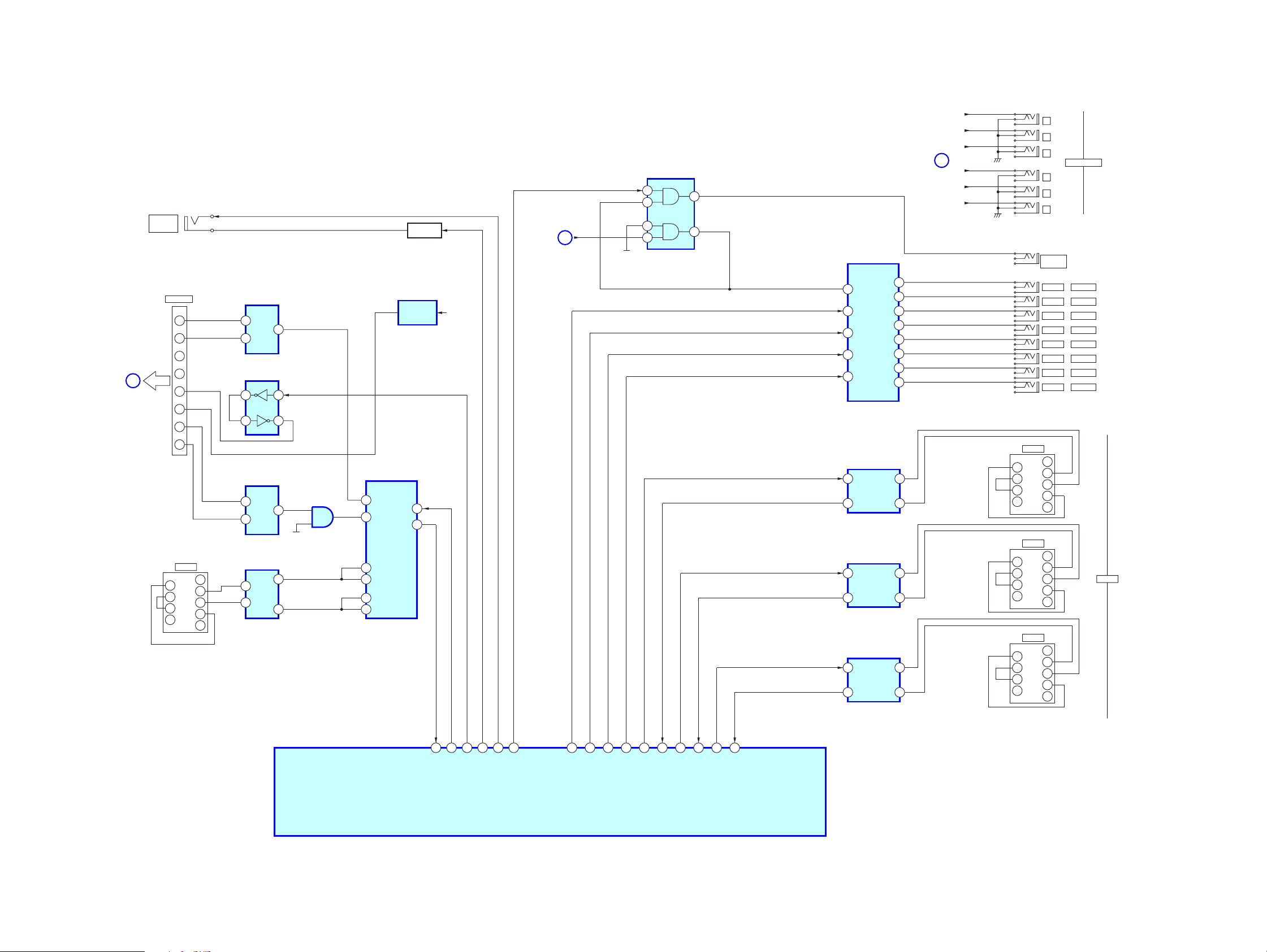
3-5. BLOCK DIAGRAM — IR OUT/RS232C/12V TRIGGER SECTION —
RF REMOTE/
RF ANTENNA
SECTION
DSR
2
4
RTS
CTS
6
8
NC
DSR
2
4
RTS
CTS
6
8
NC
DSR
2
4
RTS
CTS
6
8
NC
CN300
STR
CN310
DVP
CN320
AUX
J211
J212
J213
J214
J215
J216
(COMMON)
SD
SD
SD
1
2
3
12V TRIGGER
4
5
6
J209
IR OUT
J208
SOURCE 8
IR OUT
J207
IR OUT SOURCE 7
J206
IR OUT SOURCE 6
J205
IR OUT SOURCE 5
J204
IR OUT SOURCE 4
J203
IR OUT SOURCE 3
J202
IR OUT SOURCE 2
J201
IR OUT SOURCE 1
1CD
3RXD
5TXD
7DTR
9
1CD
3RXD
5TXD
7DTR
9
1CD
3RXD
5TXD
7DTR
9
RS232C
12V 1
12V 2
MAIN/POWER
T1OUT
R1OUT
T1OUT
R1OUT
T1OUT
R1OUT
SECTION
7
4
6
2
5
5
4
1
3
12
2
15
1
14
0
13
17
16
17
16
17
16
IC200
AND GATE
1
J2009
CONTROL
A1 II
CN2700
ANTENNA
TX-
1
TX+
2
3
H
4
IR
5
6
RX+
7
RX-
8
CN750
RS232C
1CD
DSR
2
3RXD
4
RTS
5TXD
CTS
6
7DTR
8
NC
SD
9
IC2700
DIFFERENTAL
BUS TRANSCEIVER
B
7
D1
4
A6
IC2710
BUFFER
7
1
6
2
IC2720
DIFFERENTAL
BUS TRANSCEIVER
B
7
R0 1
6
A
IC750
LINE DRIVER RECEIVER
T1IN
13
16
R1OUT
T1OUT
17
15
R1IN
IC508
ANALOG MULTIPLEX
IC520
BUFFER
12
13
+5V
1
Y
11
12
X
2
5
14
15
Y-COM
X-COM
SWITCH
IC2730
+12V REG
3
13
Q506
RY12V
MAIN/POWER
SECTION
A
2
4
5
+5V
3
6
IC201
ANALOG MULTIPLEX
3
COM
11
A
10
B
9
C
6
INH
IC300
LINE DRIVER RECEIVER
13
T1IN
15
R1OUT
IC310
LINE DRIVER RECEIVER
13
T1IN
15
R1OUT
IC320
LINE DRIVER RECEIVER
13
T1IN
15
R1OUT
12V 3
B
12V 4
12V 5
12V 6
CAV-M1000ES
IC500 (3/5)
SYSTEM CONTROLLOR
110
109
108
51
86
RF RX
RF TX
CTRL
A1 OUT
AI OUT
39
IROUT D
37
IROUT A35IROUT B36IROUT C
38
IROUT INH
112
RS232 1 TX
113
RS232 1 RX
106
RS232 2 TX
107
RS232 2 RX
103
RS232 3 TX
104
RS232 3 RX
1818
3-6. BLOCK DIAGRAM — RF REMOTE/RF ANTENNA SECTION —
CAV-M1000ES
RF SIGNAL
L103
L102
IC101
HYBRID TRANSMISSION
20
RFIO
RXDATA
GND1
TXMOD
CNTRL0
CNTRL1
1
7
8
18
17
S802
V
(PUSH)
S807
S806
S805
VOLUME +
VOLUME -
MUTING
V
V
V
INVERTER
6
5
IC102
S801
2
3
S803
S804
SYSTEM OFF
DATA OUT
DATA IN
CHANNEL +
CHANNEL -
CNT0
CNT1
CN3
CN2
(CPU-2P)
(CPU-1P)
(CPU-62P)
(CPU-5P)
(CPU-3P)
(CPU-60P)
(CPU-4P)
[PA UNIT]
CN1
TOUCH PANEL
CN710
CN201
TRANSLATION BOARD
TP
D501-504
CN203
CN202
CN1
[INVERTER UNIT]
CN2
LIQUID CRYSTAL DISPLAY
CHARGE UNIT
T501
HYBRID TRANSCEIVER
20
RFIO
IC3802
RX DATA
TX MOB
CNT RL1
VCC (+3V)
7
8
17
3 1
IC3801
+3V REG
3
6
10
9
IC3803
INVERTER
(CPU-61P)
IC3720
DIFFERENTAL BUS TRANSEIVER
6
A
4
5
11
8
VCC (+5V)
4
DI
7
B
IC3700
DIFFERENTAL BUS TRANSEIVER
6
A
1
DI
7
B
IC3800
3 1
+5V REG
8
TX-
7
TX+
6
12V
5
IR
IR OUT/RS232C/
12V TRIGGER
H
SECTION
2
RX-
1
RX+
CAV-M1000ES
1919
CAV-M1000ES
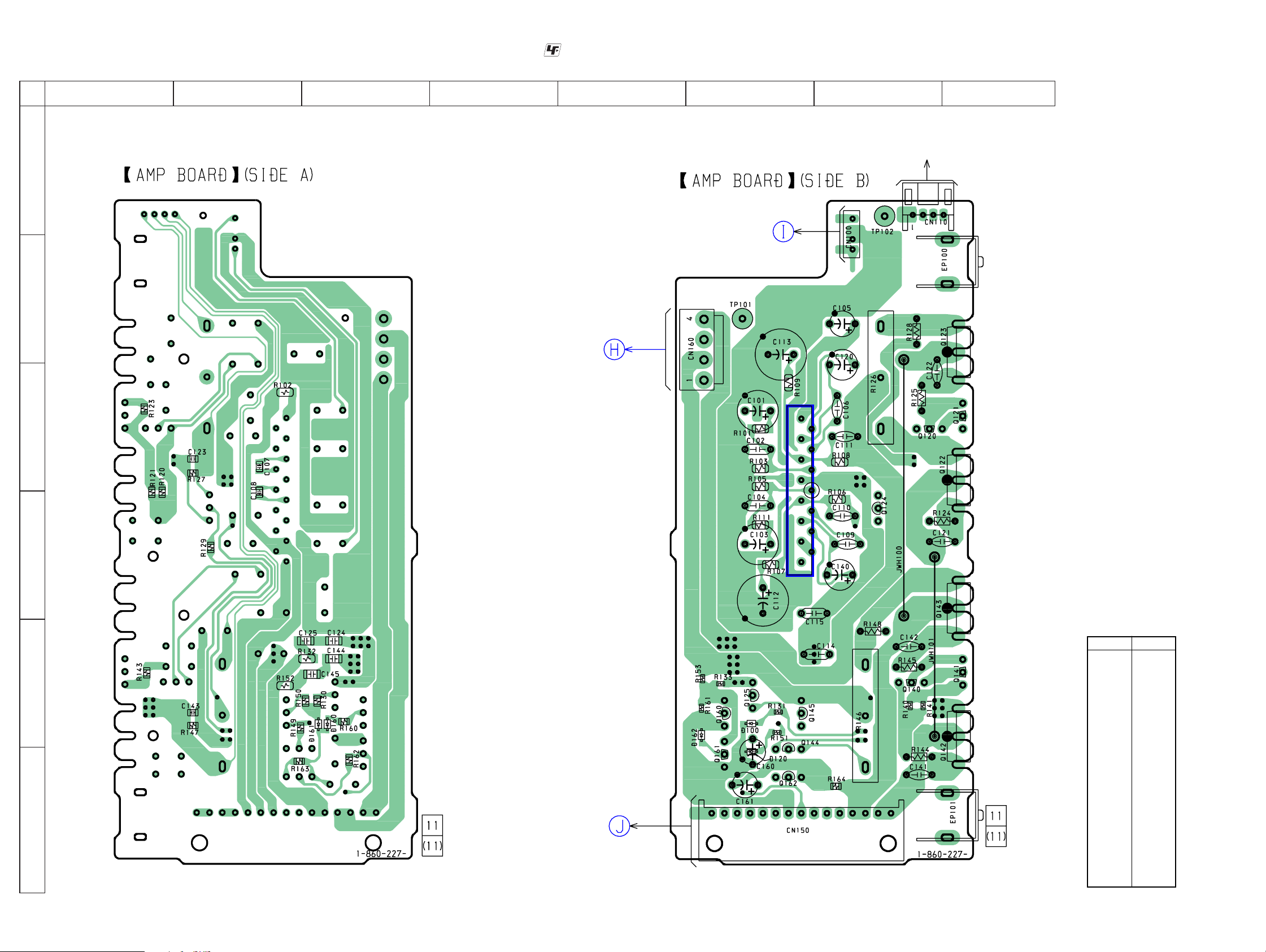
3-7. PRINTED WIRING BOARD — AMP SECTION —
12
A
B
C
• See page 12 for Circuit Boards Location. :Uses unleaded solder.
345678
FOR
( )
CHECK
1
3
E
E
E
SPEAKER
BOARD
CN11,CN22,
CN33,,CN44,
CN55,CN66
(Page 40)
AUDIO I/O BRD
BOARD
CN1005,
CN1008
(Page 25)
1
2
D
E
F
AMP BASE
BOARD
CN810,CN820,
CN830,CN840,
CN850,CN860
(Page 23)
E
IC100
14
15
E
E
E
15 1
E
E
E
E
• Semiconductor
Location
Ref. No.
E
E
E
D100 E-6
D120 F-6
D160 E-3
D161 E-3
D162 E-6
IC100 D-6
Q120 C-7
Q121 C-8
Q122 C-7
Q123 B-7
Q124 C-7
Q125 E-6
Q140 E-7
Q141 E-8
Q142 E-7
Q143 D-7
Q144 F-6
Q145 E-6
Q160 E-6
Q161 F-6
Q162 F-6
Location
CAV-M1000ES
2020
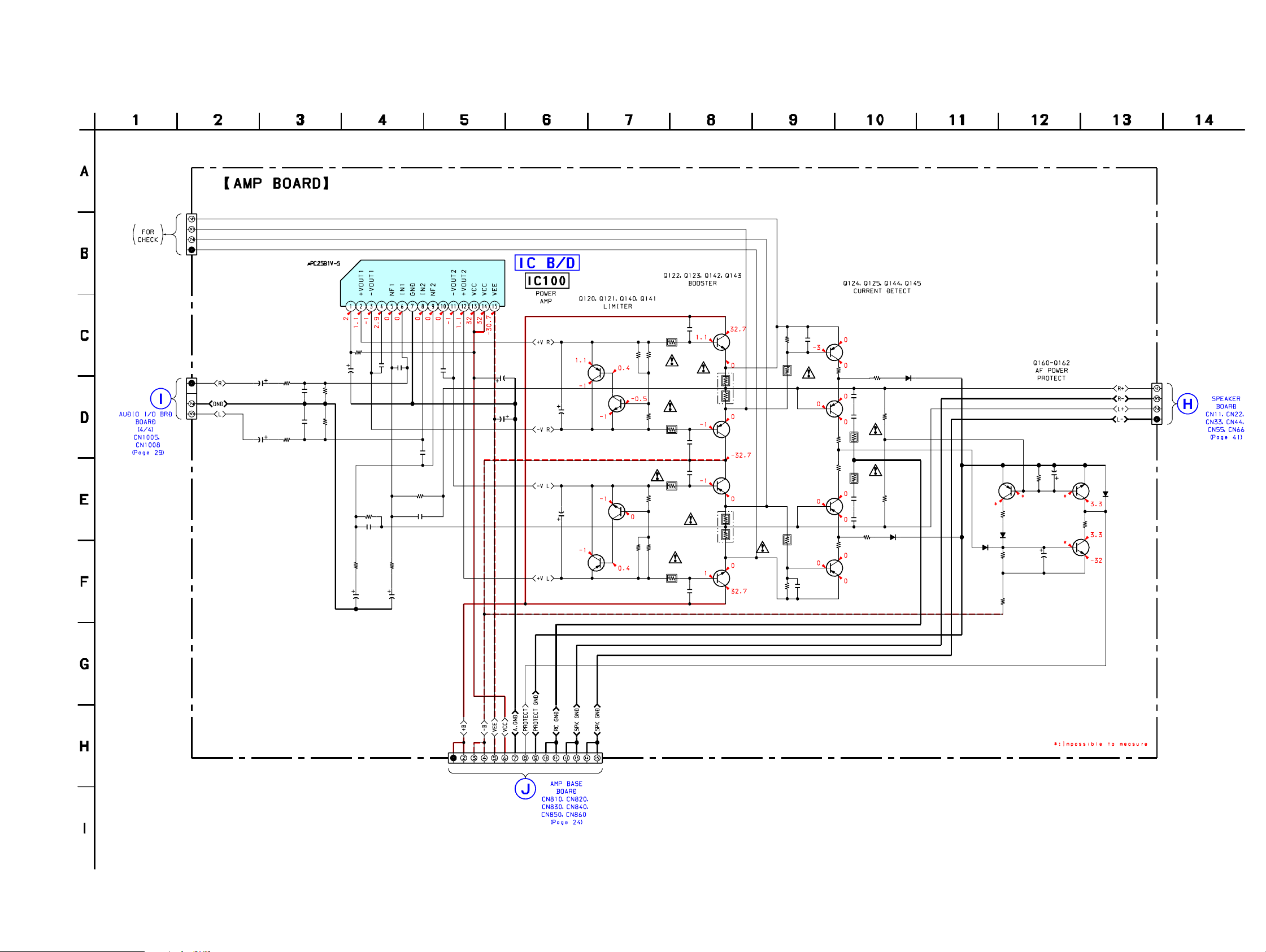
CAV-M1000ES
3-8. SCHEMATIC DIAGRAM — AMP SECTION —
1k
C104
50V
IC100
C105
C102
0.0001
1k
100V
50V
R103
R105
68k
CN110
CN100
4P
R101
C101
22
25V
0.0001
3P
C103
R111
22
25V
• See page 62 for IC Block diagram.
R102
22k
C106
33p
500V
2.2
68k
R107
2.7k
C112
220
25V
R106
68k
C110
3p
C113
220 25V
C107
100p
R109
2.7k
C108
100p
R108
68k
C111
500V
33p
C109
3p
C115
0.047
Q122
2SD2560
C121
47p
R141
R121
82k
82k
R145
100
R125
100
R144
100
R124
100
Q123
2SB1647
C122
47p
C142
47p
Q143
2SB1647
R146
0.22
C141
47p
R126
0.22
Q142
2SD2560
R120
Q121
2SC3623ATP-LK
Q141
2SC3623ATP-LK
Q140
2.2k
R140
2.2k
R143
R123
560
560
C114
0.047
50V
50V
C120
C140
50V
Q120
2SA1115TP-EF
47
50V
47
2SA1115TP-EF
R127
4.7k
C123
220p
R128
6.2k
Q125
2SA988TP-PAFAEA
2SA988TP-PAFAEA
R148
6.2k
C143
R147
220p
4.7k
Q145
R149
1.5k
R129
1.5k
R130
68k
R150
68k
Q124
2SA988TP-PAFAEA
R131
15k
C124
0.01
C125
0.01
R132
10
R152
10
C145
0.01
C144
0.01
R151
15k
1SS355TE-17
Q144
2SA988TP-PAFAEA
1SS355TE-17
R133
47k
R153
47k
D120
D100
2SA988TP-PAFAEA
R160
10k
D161
1SS355TE-17
R164
1k
Q160
R161
47k
D160
1SS355TE-17
R163
39k
C160
220
10V
Q161
2SC2785TP-FEK
C161
10
50V
2SC1841TP-PAFAEA
Q162
R162
6.8k
D162
1SS355TE-17
CN160
4P
CAV-M1000ES
CN150
15P
2121
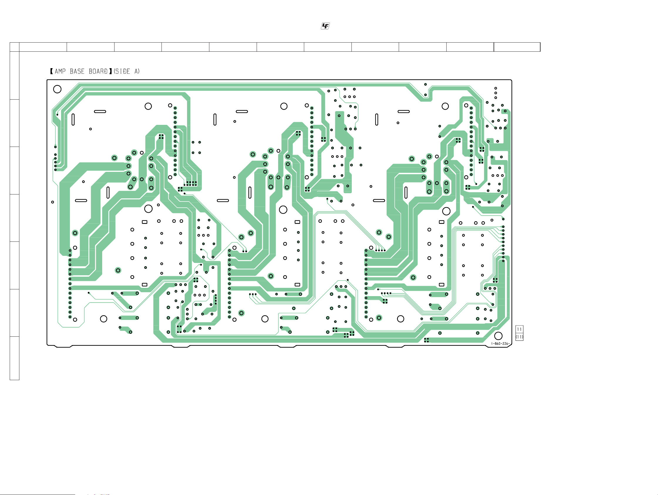
CAV-M1000ES
3-9. PRINTED WIRING BOARD — AMP BASE SECTION (SIDE A) —
12
34567891011
A
B
C
• See page 12 for Circuit Boards Location. :Uses unleaded solder.
D
E
F
G
CAV-M1000ES
2222
CAV-M1000ES
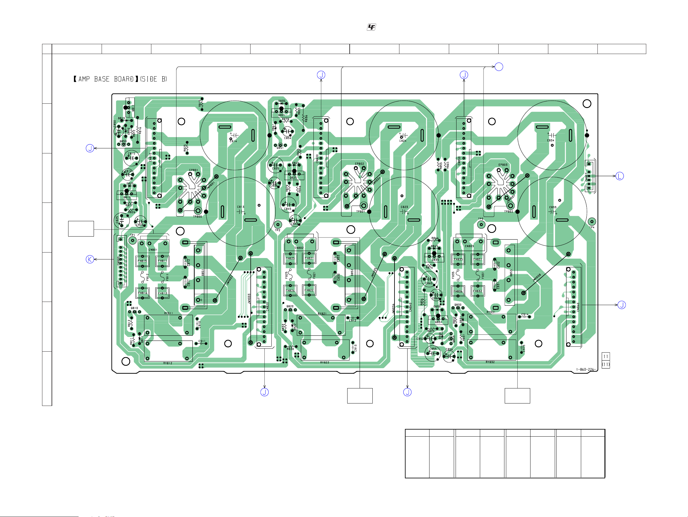
3-10. PRINTED WIRING BOARD — AMP BASE SECTION (SIDE B) —
12
3456789101112
A
BLACK
E
1
B
E
AMP
BOARD
CN150
(Page 20)
C
E
15
• See page 12 for Circuit Boards Location. :Uses unleaded solder.
AMP
BOARD
CN150
(Page 20)
E
1
E
E
15
BLUE
AMP
BOARD
CN150
(Page 20)
AUDIO I/O BRD
BOARD
O
CN1009
(Page 25)
RED
1
1
15
6
SPEAKER
BOARD
CN12
(Page 40)
D
E
F
G
T901
POWER
TRANSFORMER
DISPLAY
BOARD
CN503
(Page 34)
1
13
15
11
E
1
AMP
BOARD
CN150
(Page 20)
13
E
E
E
E
1
T901
POWER
TRANSFORMER
AMP
BOARD
CN150
(Page 20)
13
1515
E
1
T901
POWER
TRANSFORMER
AMP
BOARD
CN150
(Page 20)
CAV-M1000ES
• Semiconductor Location
Ref. No.
Location
D811 F-2
D815 B-2
D822 F-5
D825 C-2
D831 F-9
D835 B-5
D845 C-5
Ref. No.
D850 B-2
D851 E-3
D852 E-6
D853 E-10
D855 F-8
D861 B-5
D865 E-8
Location
Ref. No.
Location
D866 F-8
Q810 F-2
Q811 B-2
Q815 C-2
Q820 F-5
Q821 B-5
Ref. No.
Location
Q825 C-5
Q830 F-9
Q831 F-8
Q835 E-8
Q850 B-2
Q851 C-5
Q853 F-8
2323
CAV-M1000ES
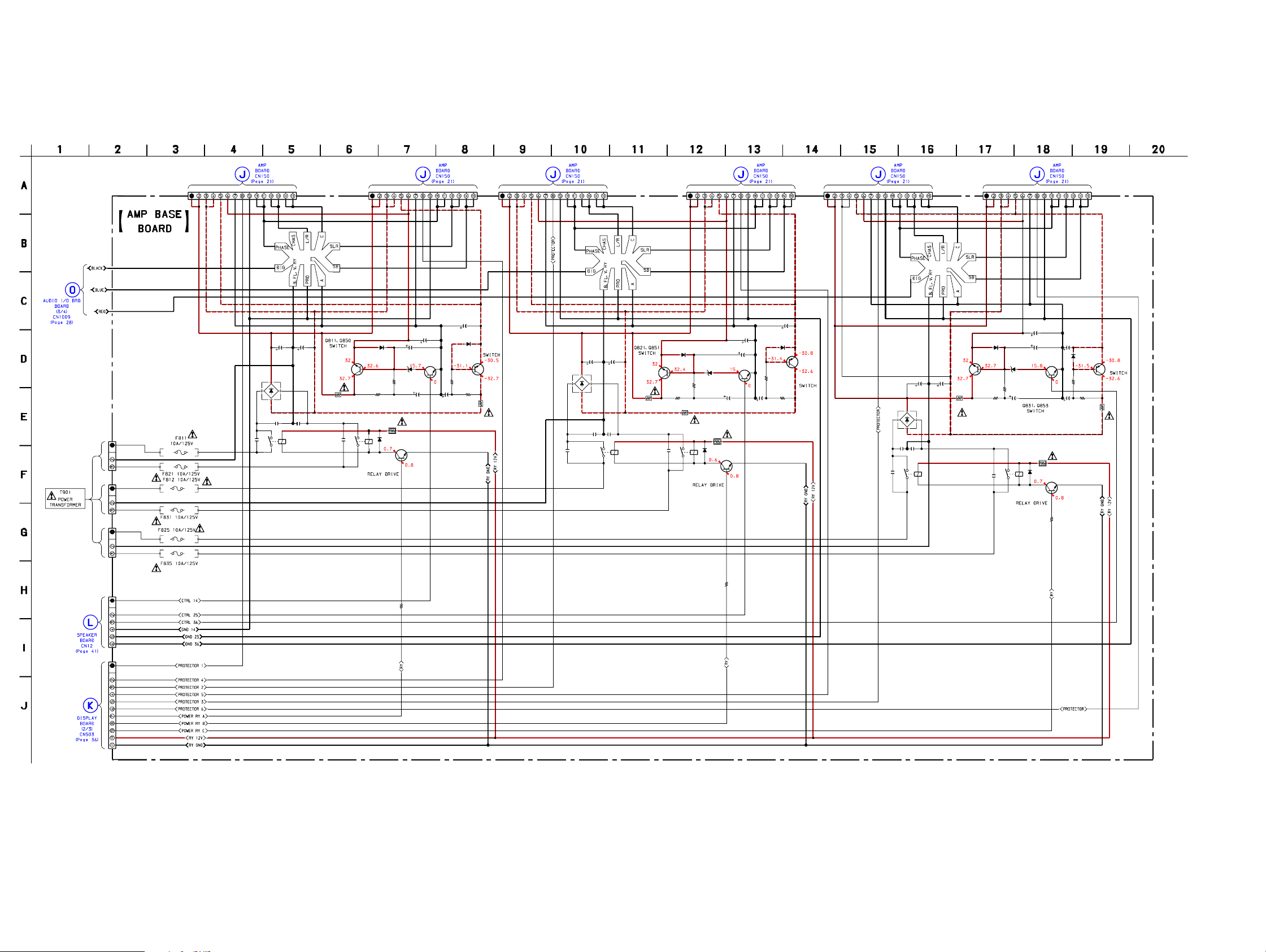
3-11. SCHEMATIC DIAGRAM — AMP BASE SECTION —
CN801
CN802
CN803
C823 C824
10000
71V
C830
0.22 0.22
1
2
8
Y
R
10000
C853
CN830
15P
71V
2SD2396K
Q811
2SD2396K
R815
1
C911
0.1
CN820
15P
EP802
C826
22
C816
22 63V
C850
4.7 5 0V
D815
10EDB40-TB5
R816
4.7k
2
1
8
Y
R
Q810
2SC2785TP-FEK
R872
470
10EDB40-TB5
R811
47
MTZJ-T-72-18A
D811
Q850
2SC1841TP-PAFAEA
D850
C815
47
63V
63V
D825
10EDB40-TB5
Q815
2SB1565E
D852
RBV-2506
R877
470
R826
C825
47
63V
R825
1
4.7k
C912
0.1
CN810
15P
EP801
C813
C814
10000
10000
71V
71V
D851
RBV-2506
C811 C812
0.22 0.22
.1
1
0
1
3P
3P
FH811
FH815
FH821
FH825
3P
FH831
FH812
FH816
FH822
FH826
FH832
8
0
Y
1
R
9
C
CN840
15P
C836
22
63V
D845
10EDB40-TB5
D835
10EDB40-TB5
Q821
R835
R836
1
4.7k
3
1
.1
9
0
C
D861
MTZJ-T-72-18A
R878
470
2SC1841TP-PAFAEA
R845
1
2
2
8
10EDB40-TB5
Y
R
Q820
2SC2785TP-FEK
C854
4.7
50V
R879
C845
47 63V
470
Q851
C835 C855
47
63V
R830
47
D822
CN850
15P
EP803
C846
22 63V
Q825
2SB1565E
R846
4.7k 4.7k
C914
0.1
D853
RBV-2506
C831
0.22
1
3
8
Y
R
C834
C833
10000
10000
71V
71V
C832
0.22
R855 R865
1
Q831
2SD2396K
C915
0.1
D855
10EDB40-TB5
R875
470
R856
4.7k
MTZJ-T-72-18A
2SC1841TP-PAFAEA
47
63V
2
3
8
Y
R
D866
Q853
Q830
2SC2785TP-FEK
C856
22 63V
C852
4.7 5 0V
R831
47
D831
10EDB40-TB5
R832
4.7k
CN860
15P
C866
22
63V
D865
10EDB40-TB5
R876
470
R866
C865
47
63V
Q835
2SB1565E
1
CN807
CN800
FH835
6P
11P
FH836
R833
4.7k
R812
4.7k
CAV-M1000ES
2424

CAV-M1000ES
3-12. PRINTED WIRING BOARD — AUDIO I/O BRD SECTION —
12
345678910111213
A
B
IC1601
IC1501
C
D
IC1900
E
AC INLET
F
G
BOARD
CN881
(Page 53)
13
IC1002
112
• See page 12 for Circuit Boards Location. :Uses unleaded solder.
IC1702 IC1701
IC1602
IC1502
IC1401
IC1302
IC1402
IC1301
IC1102
IC1202
PRE OUT BRD
BOARD
CNP102
(Page 44)
AMP
BOARD
CN100
(Page 20)
19
19
AMP
BOARD
CN100
(Page 20)
18
PRE OUT BRD
BOARD
CNP101
(Page 44)
IC1700
IC1800
IC1201
IC1101
• Semiconductor
Location
Ref. No.
IC1001 H-2
IC1002 G-2
IC1010 I-11
IC1011 I-11
IC1020 I-10
IC1021 I-9
IC1030 I-9
IC1031 I-9
IC1040 I-8
IC1041 I-7
IC1050 I-7
IC1051 I-6
IC1060 I-6
IC1061 I-5
IC1070 I-5
IC1071 I-4
IC1080 I-3
IC1081 I-3
IC1100 H-11
IC1101 C-11
IC1102 D-9
IC1200 H-10
IC1201 D-11
IC1202 D-8
IC1300 H-9
IC1301 C-9
IC1302 D-7
IC1400 H-6
IC1401 C-6
IC1402 D-6
IC1500 H-4
IC1501 C-4
IC1502 D-5
IC1600 H-3
IC1601 C-3
IC1602 D-5
IC1700 C-10
IC1701 C-7
IC1702 C-5
IC1800 D-10
IC1900 D-3
Location
H
I
J
CAV-M1000ES
AMP BASE
BOARD
TP800,
TP801,
TP802
(Page 23)
IC1001
13
IC1600
IC1081 IC1071
AUDIO OUT
IC1080 IC1070 IC1060
AUDIO IN AUDIO OUT
SOURCE 8
IC1500
AUDIO IN AUDIO OUT
SOURCE 7
IC1061
AUDIO IN AUDIO OUT
SOURCE 6
IC1400
IC1051
IC1050
AUDIO IN AUDIO OUT
SOURCE 5
IC1200
IC1300
IC1100
IC1041 IC1040 IC1031 IC1030 IC1021 IC1020 IC1011
AUDIO IN AUDIO OUT
SOURCE 4
AUDIO IN AUDIO OUT
SOURCE 3
AUDIO IN AUDIO OUT
SOURCE 2
2525
SOURCE 1
IC1010
AUDIO IN
CONNECTOR
BOARD
CN103
(Page 50)
CAV-M1000ES
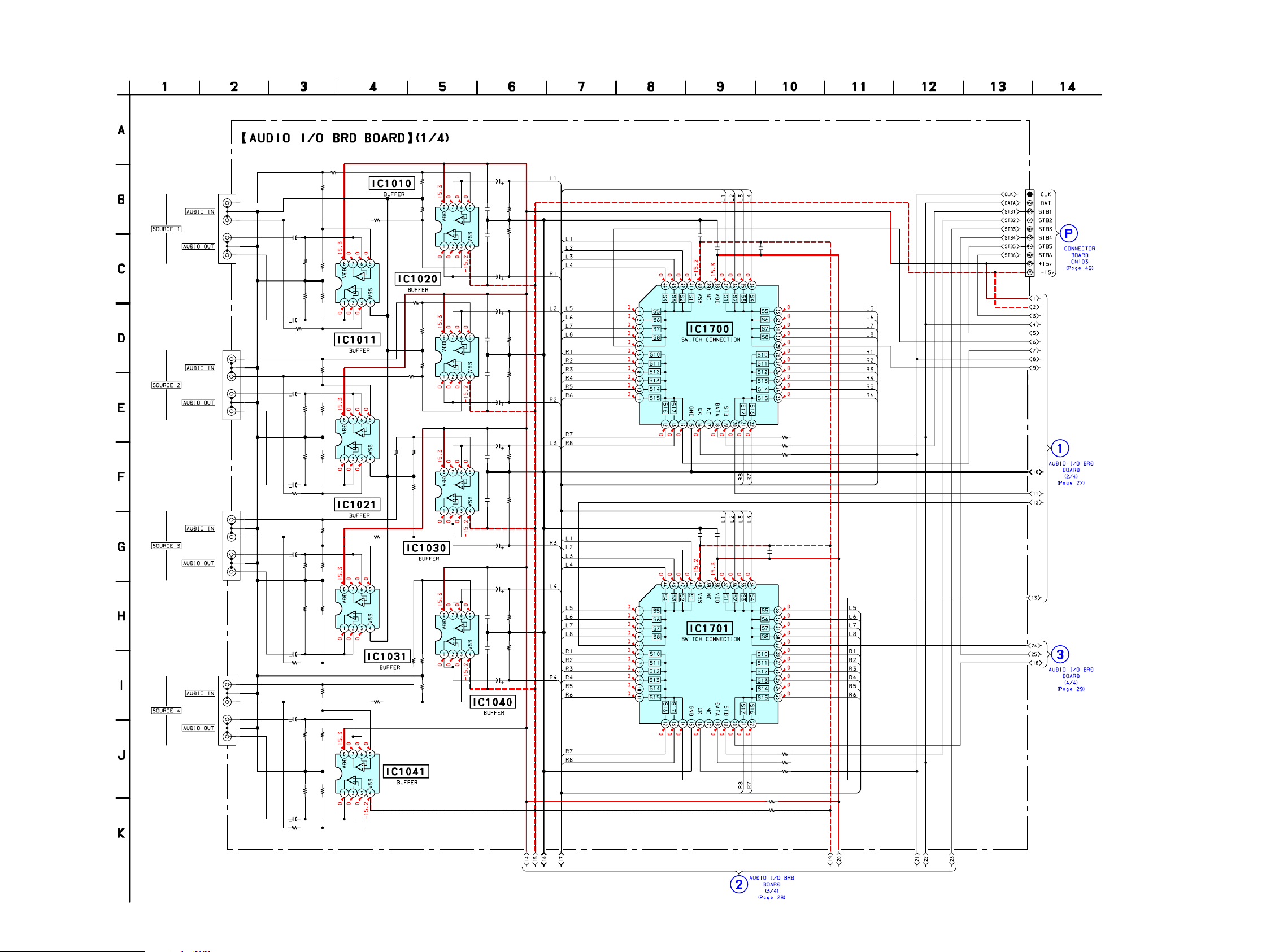
3-13. SCHEMATIC DIAGRAM — AUDIO I/O BRD SECTION (1/4) —
R1010
1k
R1180
1k
J1010
C1183
22
35V
R1182
R1181
100k
100k
IC1011
R1186
100k
NJM4580MD-(TE2)
1k
R1280
1k
R1281
100k
IC1021
R1286
100k
NJM4580MD-(TE2)
R1380
1k
R1381R1382
100k100k
R1386
100k
IC1031
NJM4580MD-(TE2)
R1480
1k
J1040
J1020
J1030
C1188
R1282
R1287
C1288
R1387
R1187
100k
22
35V
C1283
100k
100k
22
35V
R1285
C1383
100k
C1388
22
35V
R1385
C1483
22
35V
R1185
35V
1k
35V
1k
22
22
R1015
R1035
R1045
C1013
22
C1022
0.0022
C1038
C1017
0.0022
C1018
C1027
0.0022
0.0022
C1037
0.0022
22
35V
C1042
0.0022
C1047
0.0022
C1048
C1012
0.0022
22
35V
C1023
C1028
C1033
C1032
C1043
22
35V
35V
R1012
100k
R1017
100k
22
35V
R1022
100k
R1027
100k
22
35V
22
35V
R1032
100k
R1037
100k
22
35V
R1042
100k
R1047
100k
C1700
0.0022
C1705
0.0022
C1701
IC1700
TC9274F-021
C1706
0.0022
IC1701
TC9274F-021
0.0022
C1715
0.01
R1701
C1716
0.01
R1700
R1702
CN1000
10P
100
100
100
R1011
100k
R1016
100k
1k
IC1010
NJM4580MD-(TE2)
R1020
1k
R1021
100k
R1026
IC1020
100k
NJM4580MD-(TE2)
R1025
1k
R1030
100k
1k
R1031
R1036
100k
IC1030
NJM4580MD-(TE2)
1k
IC1040
NJM4580MD-(TE2)
1k
R1041
100k
R1040
R1046
1k
100k
CAV-M1000ES
R1485
R1487
C1488
1k
100k
35V
R1481R1482
100k100k
IC1041
R1486
100k
NJM4580MD-(TE2)
22
R1003
R1004
R1703
R1704
R1705
33
33
100
100
100
2626
CAV-M1000ES
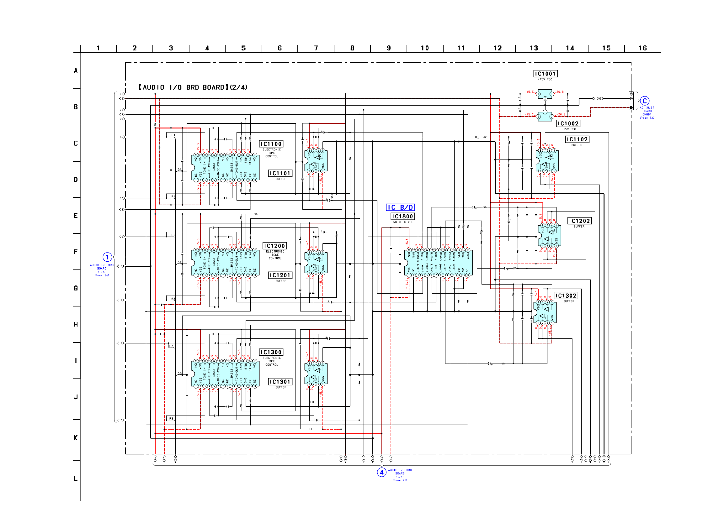
3-14. SCHEMATIC DIAGRAM — AUDIO I/O BRD SECTION (2/4) —
33
R1001
C1270
C1370
0.01
R1002
33
0.022
C1100
C1170
0.01
C1200
0.022
0.01
C1350
0.022
C1150
0.022
C1250
0.022
C1300
0.022
C1101
0.0033
C1201
0.0033
C1251
0.0033
C1301
0.0033
C1103
0.015
C1153 C1154
0.015 0.015
C1151
C1203
0.015
C1253 C1254
0.015 0.015
C1303
0.015
C1353
0.015
C1351
0.0033
0.0033
C1104
0.015
C1204
0.015
C1304
0.015
C1354
0.015
• See page 62 for IC Block diagram.
10k
100
R1102
R1200
10k
R1150
R1100
10k
10k
R1350
10k
R1250
10k
R1300
R1101
R1201
100
R1301
R1202
R1251
R1151
100
100
R1302
R1351
100
IC1100
TC9481F
100
100
IC1200
TC9481F
100
IC1300
TC9481F
100
C1107
C1157
0.0022
0.0022
C1207
0.0022
C1307
C1357
C1257
0.0022
0.0022
0.0022
C1359
15p
C1158
15p
C1258
15p
C1358
22
35V
C1108
C1209
C1208
C1308
15p
22
35V
C1159
35V
15p
C1309
15p
C1109
22
35V
IC1101
NJM4580MD-(TE2)
R1153
100k
22
R1203
100k
IC1201
NJM4580MD-(TE2)
C1259
22
35V
22
35V
IC1301
NJM4580MD-(TE2)
100k
R1103
100k
R1253
R1303
R1353
IC1001
M5F7815L
C1001
1000
16V
C1004
1000
16V
C1312
C1362
0.022
0.022
C1212
C1262
0.022
0.022
IC1002
M5F7915L
C1110
22
R1104
35V 1k
C1111
R1105
100p
100k
R1155
100k
C1210
22
R1204
35V
1k
R1154
1k
C1310
22
35V
C1360
22
35V 1k
C1160
R1354
22
35V
C1260
35V
R1305
R1355
R1802
100
10k
100
R1800
R1801
R1304
1k
0.01
C1803
C1800
0.022
IC1800
TC9482F(EL)
C1850
0.022
R1850
R1851
100
10k
100k
100k
C1112
0.022
C1161
100p
C1162
0.022
C1211
R1205
100k
100p
R1255
C1261
100k
100p
R1254
22
1k
100p
100k
C1311
C1361
100p
100k
C1000
0.047
C1003
0.047
IC1102
NJM4580MD-(TE2)
IC1202
NJM4580MD-(TE2)
IC1302
NJM4580MD-(TE2)
CN1100
3P
CAV-M1000ES
2727
CAV-M1000ES
3-15. SCHEMATIC DIAGRAM — AUDIO I/O BRD SECTION (3/4) —
R1050
R1051
1k
100k
J1050
J1060
CN1009
3P
E1
BRACKET
C1683
C1688
22
35V
22
35V
R1680
1k
C1583
35V
R1056
100k
R1055
1k
1k
R1580
22
R1582
R1581
100k
100k
R1586
100k
R1587
100k
C1588
22
35V
1k
R1585
R1060
1k
R1061
100k
R1066
R1065
100k
1k
R1682
100k
R1687
100k
R1681
R1686
100k
IC1051
100k
D-(TE2)
4580M
JM
N
-(TE2)
D
IC1061
4580M
JM
N
D-(TE2)
IC1050
4580M
JM
N
C1062
0.0022
IC1060
C1067
0.0022
-(TE2)
D
4580M
NJM
C1053
C1052
0.0022
C1057
0.0022
C1058
C1063
C1068
C1073
22
35V
R1052
100k
R1057
100k
22
35V
22
R1062
35V
100k
C1710
C1711
0.0022 0.0022
R1067
100k
22
35V
22
35V
7
C171
1
0.0
J1070
J1080
C1783
R1782
100k
R1787
100k
C1788
R1685
1k
R1780
R1785
1k
R1085
1k
R1781
100k
R1786
100k
1k
22
35V
22
35V
R1080
R1081
100k
R1086
100k
R1070
1k
R1071
100k
D-(TE2)
IC1070
4580M
R1076
100k
R1075
D-(TE2)
IC1071
4580M
JM
N
1k
NJM
1k
C1077
0.0022
1080
IC
-(TE2)
D
4580M
JM
N
C1072
0.0022
C1078
C1083
C1082
0.0022
C1088
22
35V
35V
C1087
22
35V
22
0.0022
R1072
100k
R1077
100k
R1082
100k
R1087
100k
22 35V
R1882
100k
R1854
100k
C1888
C1883
22
35V
R1880
IC1702
TC9274F-021
R1706
100
R1707
100
R1708
100
1k
R1881
100k
R1853
100k
R1852
1k
1081
IC
)
D-(TE2
4580M
JM
N
CAV-M1000ES
2828
CAV-M1000ES
3-16. SCHEMATIC DIAGRAM — AUDIO I/O BRD SECTION (4/4) —
C1401
0.0033
C1403 C1404
0.015
C1400
0.022
C1470
0.01
C1450
0.022
C1451
0.0033
C1501
0.0033
C1503 C1504
0.015
C1570
C1500
0.01
0.022
C1550
0.022
C1553 C1554
0.015 0.015
C1551
0.0033
C1601
0.0033
C1603
0.015 0.015
C1600
0.022
0.01
C1670
C1650
0.022
C1653
0.015
C1651
0.0033
• See page 62 for IC Block diagram.
C1407
0.015
C1604
0.015
C1654
0.015
0.0022
100
R1402
10k
100
R1401
R1400
IC1400
TC9481F
IC1401
NJM4580MD-(TE2)
10k
R1451
100
R1500
R1450
100
R1502
10k
10k
R1550
10k
R1600
10k
R1650
R1501
100
R1601
100
R1602
R1551
100
100
R1651
100
C1454C1453
0.0150.015
C1507
0.0022
IC1500
IC1600
TC9481F
TC9481F
C1458
15p
C1457
IC1501
NJM4580MD-(TE2)
C1558
15p
C1657
0.0022
0.0022
C1658
15p
C1557
C1607
0.0022
0.0022
C1408
C1508
C1409
15p
C1509
15p
35V
R1503
22
35V
R1403
100k
R1453
100k
C1459
22
100k
C1559
C1608
22
35V
35V
15p
C1659
22
C1609
22
35V
22
35V
R1553
100k
IC1601
NJM4580MD-(TE2)
R1603
100k
R1653
CN1001
8P
C1410 R1404
22
1k
35V
R1902
10k
100
100
R1900
R1901
0.01
C1903
100k
C1900
C1950
0.022
0.022
IC1900
TC9482F(EL)
10k
R1951
100
R1950
C1560
22
35V
C1660R1654
22
35V
C1610
22
35V
R1604
1k
R1554
1k
R1605
100k
R1655
100k
1k
R1405
R1455
C1611
C1661
100p
100k
100k
R1454
C1460
100p
C1411
100p
C1412
0.022
IC1402
NJM4580MD-(TE2)
C1461
100p
C1462
0.022
CN1002
12P
CN1005
9P
22
35V
C1510
R1504
1k
1k
22
35V
R1555
C1612
0.022
C1662
0.022
100p
100k
C1511
R1505
C1512
0.022
IC1502
100p
100k
C1561
C1562
0.022
NJM4580MD-(TE2)
IC1602
NJM4580MD-(TE2)
CN1008
9P
CAV-M1000ES
2929
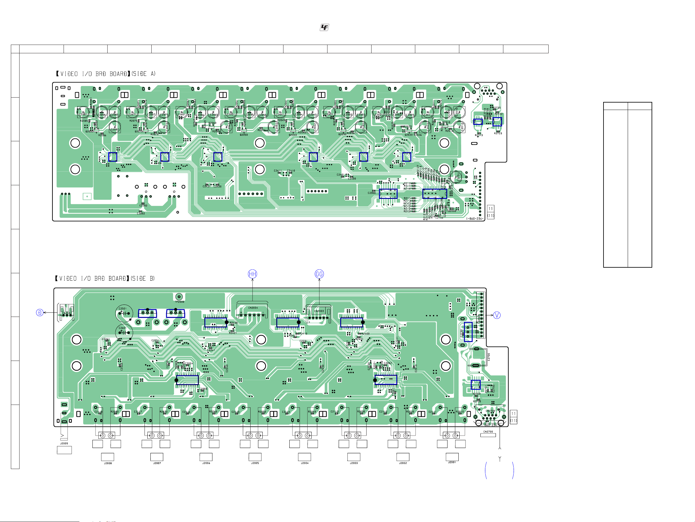
CAV-M1000ES
3-17. PRINTED WIRING BOARD — VIDEO I/O BRD SECTION —
12
3456789101112
A
B
C
D
• See page 12 for Circuit Boards Location. :Uses unleaded solder.
IC2230IC2240IC2250IC2260
IC2220
IC2300
IC2210
IC2100
IC2710
IC2720
• Semiconductor
Location
Ref. No.
IC2000 H-9
IC2001 H-4
IC2100 C-10
IC2210 C-9
IC2220 C-8
IC2230 C-7
IC2240 C-5
IC2250 C-4
IC2260 C-2
IC2300 D-9
IC2400 G-9
IC2410 G-6
IC2420 G-5
IC2500 F-3
IC2600 F-4
IC2700 H-11
IC2710 B-11
IC2720 C-11
IC2730 G-11
Location
E
F
G
H
AC INLET
BOARD
CN887
(Page 53)
Q2010 B-10
Q2020 B-9
Q2030 B-8
Q2040 B-7
Q2050 B-6
Q2060 B-5
Q2070 B-3
Q2080 B-2
PRE OUT BRD
BOARD
CN1106
(Page 44) (Page 44)
IC2500
1
3
1133
IC2600
10
IC2420
11
1
1
10
IC2410 IC2400
11
20
20
PRE OUT BRD
BOARD
CN1105
1
1
10
13
CZ CONNECTOR
BOARD
CN102
(Page 50)
11
20
3
1
IC2730
20
IC2000
1
11
IC2700
10
20
IC2001
1
11
10
I
CAV-M1000ES
CONTROL
A1 II
VIDEO
OUT
SOURCE
8
VIDEO
IN
VIDEO
OUT
SOURCE
7
VIDEO
IN
VIDEO
OUT
SOURCE
6
VIDEO
8
1
ANTENNA
VIDEO
VIDEO
VIDEO
VIDEO
VIDEO
VIDEO
IN
OUT
SOURCE
5
IN
VIDEO
OUT
SOURCE
4
IN
VIDEO
OUT
SOURCE
3
IN
VIDEO
OUT
SOURCE
2
IN
VIDEO
OUT
SOURCE
1
IN
CAT5
CABLE
AN-M1000
RF ANTENNA BOARD
CN3700
(Page 55)
3030
 Loading...