


®
®
®
RICOH GROUP COMPANIES
A246/A247/A248
SERVICE MANUAL
PN: RCSMA246

®
®
®
SERVICE MANUAL
A246/A247/A248
RICOH GROUP COMPANIES


A246/A247/A248
SERVICE MANUAL
PN:RCSMA246


It is the reader's responsibility when discussing the information contained within this
document to maintain a level of confidentiality that is in the best interest of Ricoh
Corporation and its member companies.
NO PART OF THIS DOCUMENT MAY BE REPRODUCED IN ANY
FASHION AND DISTRIBUTED WITHOUT THE PRIOR
PERMISSION OF RICOH CORPORATION.
All product names, domain names or product illustrations, including desktop images,
used in this document are trademarks, registered trademarks or the property of their
respective companies.
They are used throughout this book in an informational or editorial fashion only and for
the benefit of such companies. No such use, or the use of any trade name, or web
site is intended to convey endorsement or other affiliation with Ricoh products.
2000 RICOH Corporation. All rights reserved.


n
t
s
r
h
g
o
l
y
WARNING
The Service Manual contains informatio
regarding service techniques, procedures,
processes and spare parts of office equipmen
distributed by Ricoh Corporation. Users of thi
manual should be either service trained o
certified by successfully completing a Rico
Technical Training Program.
Untrained and uncertified users utilizin
information contained in this service manual t
repair or modify Ricoh equipment risk persona
injury, damage to property. or loss of warrant
protection.
Ricoh Corporation

LEGEND
PRODUCT CODE COMPANY
GESTETNER RICOH SAVIN
A246 2851 FT7950 2050
A247 2860 FT7960 2060
A248 2870 FT7970 2070
DOCUMENTATION HISTORY
REV. NO. DATE COMMENTS
*
12/98 Original Printing


A246/A247/A248 and A175/A176/A177
Product Comparison Chart

Refer to SM, pg. 2-113 for
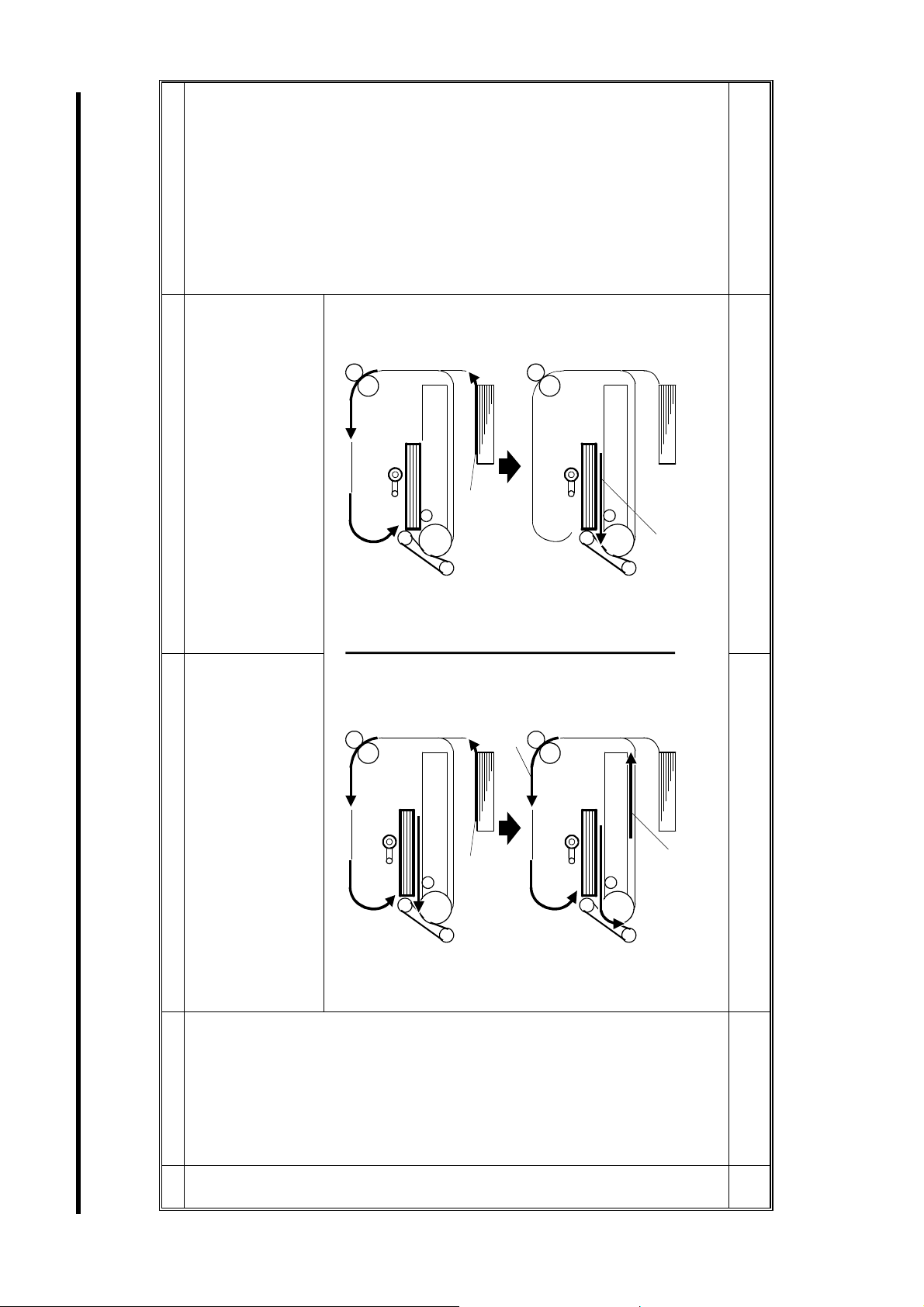
After the last sheet of copy paper is stacked
detailed information.
in the duplex tray, the next job will start.
Refer to SM, pg. 2-85/89
for detailed information.
A246G507.WMF
Last sheet
First duplex sheet
The tandem tray (capacity: 500 x 2) is the 1st
tray for (A176/A177/A191/A192 copiers).
SERIES COPIERS.
Duplex copy control has been revised. The
duplex copy productivity has been increased
Duplex copy
productivity
Last sheet
Last sheet
First duplex sheet
in the simplex to duplex mode. Before the
last sheet of copy paper is stacked in the
duplex tray, the next job will start from the
bottom stacked sheet in simplex to duplex
mode.
1st tray for easier paper replenishment.
Tandem LCT The tandem LCT (capacity: 1,550 x 2) is the
1. THE FOLLOWING TABLE SHOWS THE MAJOR DIFFERENCES BETWEEN THE A246/A247/A248 AND A175/A176/A177
No. Section/Item A246/A247/A248 A175/A176/A177 Remarks
1
2
SM 1 A246/A247/A248
Refer to SM, pg. 2-31/35
for detailed information.
Around 10% of toner is collected to the used
toner collection bottle without transferring the
Refer to SM, pg. 2-65/67
for detailed information.
The A229 (digital copier)
does not have a transfer
belt cleaning blade.
Reason:
If the toner on the transfer
belt were scraped by a
cleaning blade, some of
the normally negatively
charged toner could be
charged positively by
friction.
The positively charged
toner then could not be
removed by the cleaning
bias roller.
A246G500.WMF
toner to the copy paper.
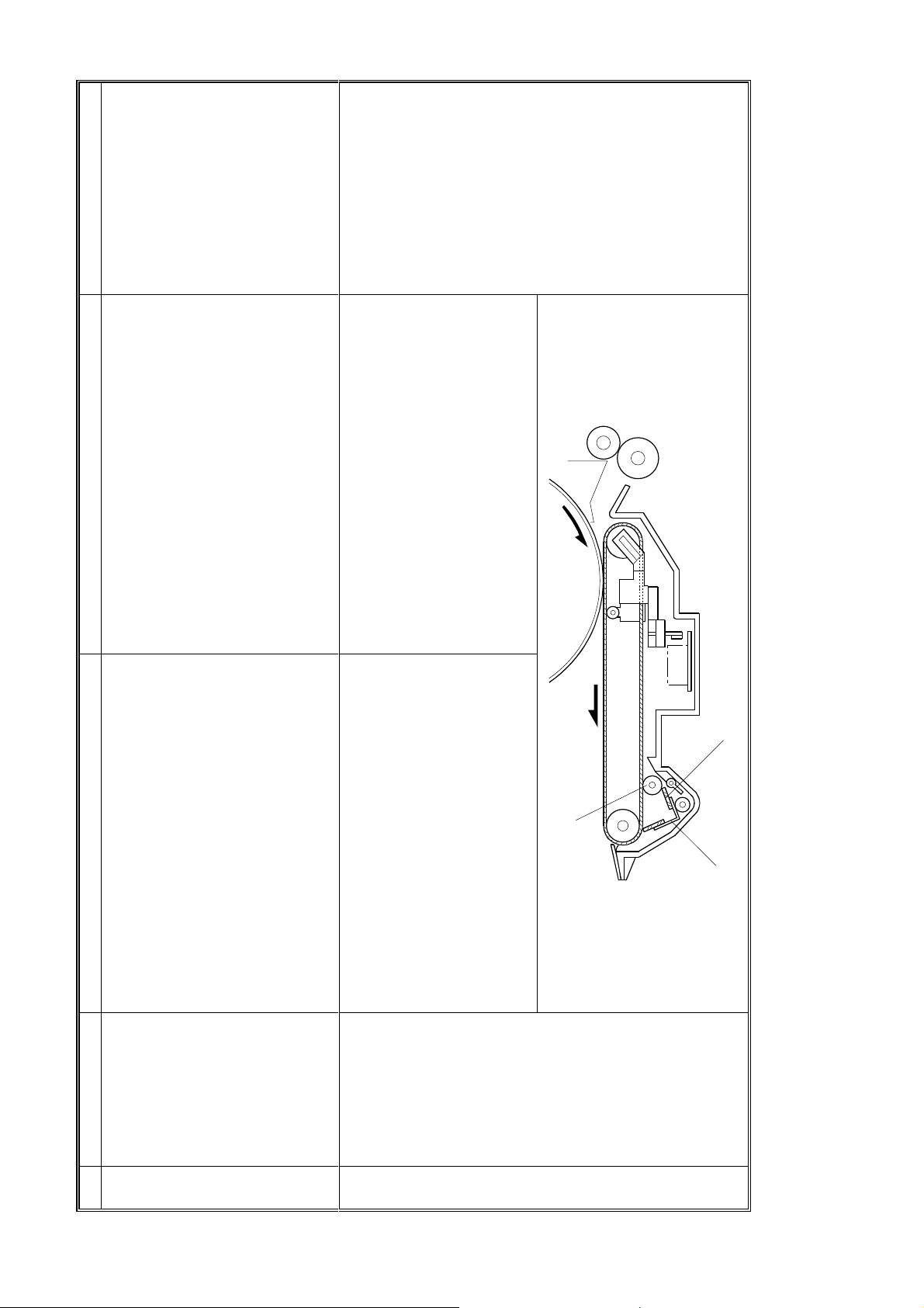
Bias Roller Blade
The toner from the drum cleaning unit and
transfer belt unit is collected and the filtering
Toner re-cycl i n g
system
No. Section/Item A246/A247/A248 A175/A176/A177 Remarks
Cleaning Bias Roller
equipment mechanism separates the re-
usable toner and unusable material (blocked
toner and paper dust). The re-usable toner is
returned to the toner tank and the unusable
material is collected in the used toner
collection bottle. About 3% of toner is
collected in the used toner collection bottle.
The estimated period before the toner
collection bottle is full has been extended
from 240 k to 1,500 k copies.
To improve the transfer belt function, a
cleaning bias roller and a bias roller blade
have been added to the transfer belt unit.
Even if the toner is not removed completely
by the transfer belt cleaning blade due to the
paper dust stuck on the transfer belt cleaning
blade, the toner is attracted to the negative
charged cleaning bias roller. The bias roller
blade scrapes off the toner on the cleaning
bias roller.
Transfer belt
cleaning bias
roller
3
4
Transfer Belt Cleaning Blade
SM 2 A246/A247/A248

Refer to SM, pg. 2-37 for
detailed information.
Refer to the Operating
Instructions.
The size of the LCD on the operation panel is
320 x 240 dots.
Refer to the Operating
Instructions
The operators have to input 2 actions of the
key operation to enter the UP mode (Clear
Refer to SM, pg. 4-8 and
SP 1-12-1 for detailed
information.
mode key and Clear/Stop key).
Additional original can be set on ADF table
during copying but the copy operation is not
continued
The process control only starts when the
fusing temperature is low. If the main switch
of the copier is not turned off during 24 hours,
the fusing temperature does not go down to
100°C. Process control cannot be carried
out.
To reduce the machine vibration while the
scanner is returning to the home position for
Optics/Scanner
return speed (70
No. Section/Item A246/A247/A248 A175/A176/A177 Remarks
70 cpm machines, the appropriate return
speed for each reproduction ratio is adapted
CPM machine)
5
so that the vibration of the machine is
added for easier access in the UP mode.
table during copying and the copy
operation is continued (totally 100
originals).
operation panel.
widened from 7 to 9. The number of
programs has been increased from 5 to
10. The digits of the user code has been
increased from 6 to 8.
SP mode.
reduced (to the 60 cpm machine level).
operation panel has been enlarged to 640 x
240 dots. For easier key operation, the layout
of the keys has been changed.
A175/A176/A177 machines have been
incorporated to facilitate machine operation.
1) The key top for the UP mode has been
2) Additional or iginals can be set on the ADF
Operation panel For easier operation, the LCD on the
Operation Improvements resulting from experience with
6
3) A sample copy key is added to the
4) T he range of the ID level has been
7
5) T he units (inch or mm) can be changed by
The process control auto start mode can be
selected in SP mode (Default: selected). To
maintain optimum copy quality, process
control occurs every 24 hours even if the
main switch is not turned off.
Process control
auto start mode
8
SM 3 A246/A247/A248
Refer to SM, pg. 2-99 for
detailed information.
Refer to SM, pg. 4-16 for
detailed information.
Developer, Type 9
EDP Code: 887797
Toner, Type 6105
EDP Code: 887801
See illustration. Refer to
SM, pg. 2-21 for detailed
information.
A246G503.WMF
A175/A176/A177A246/A247/A248
When the registration clutch turns on, the
main motor rotation may sometimes be
shocked. Jitter may appear at 80 mm from
the leading edge on small fine dotted images.
It takes longer to deliver severely curled
paper such as recycled paper or paper which
was fed as far as the duplex separation
section in the duplex unit. In latter case, the
paper guide is already up for next sheet of
paper. The paper guide cannot guide the
paper. To solve the problem, a program in
SP mode has been added.
For exit jam removal, it is necessary to open
the sorter stapler door first and then the
copier front door. Also, it is necessary to
close the copier front door first and then the
sorter stapler door.
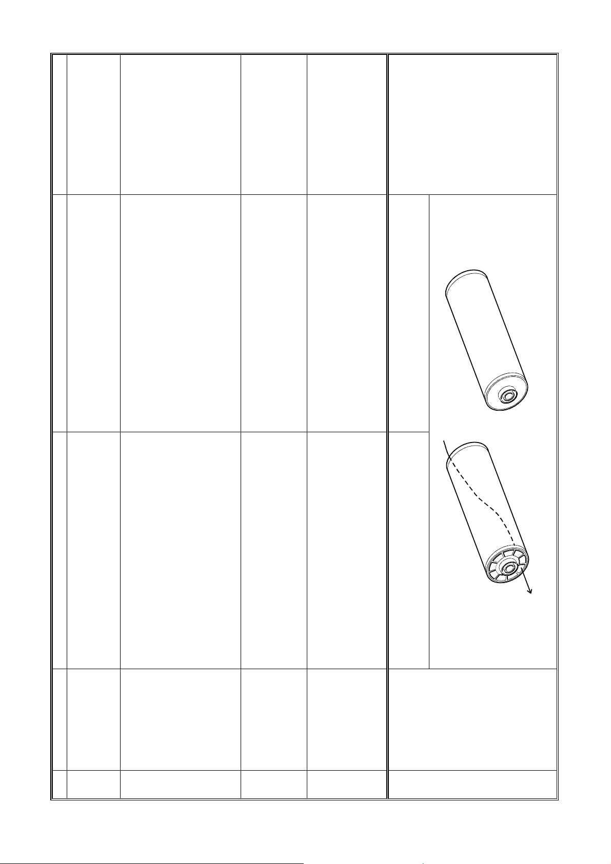
The PM cycle for replacing developer is every
120 k.
The new type drum can be installed in the
A175/A176/A177 machines.
An independent stepping motor drives the
registration roller to ensure good copy
Drive for the
registration roller
No. Section/Item A246/A247/A248 A175/A176/A177 Remarks
9
speed has increased 1.6 times from the
A177 so that the positioning roller delivers
the paper to the duplex separation section
while the paper guide is down.
changed by SP mode (1-9-1).
quality.
the following modification has been applied.
Duplex To ensure good stacking in the duplex unit,
1) T he duplex positioning roller rotation
10
2) T he positioning ro ller on timing can be
Operators can open and close either the
Exterior/Front
copier or the sorter stapler door first because
the copier door swing to the right.
doors
11
New developer is used to stabilize the
triboelectric charge after a long copy run
Developer
(300 k). The new developer maintains the
triboelectric chargeability over a long time.
This reduces the possibility of low image
density or dirty background.
To prevent the drum temperature from
increasing in the continuous duplex mode,
the drum has 12 holes in each drum flange.
Drum
12
13
SM 4 A246/A247/A248

See illustration.
The key counter holder is installed at the
copier right rear position.
Refer to SM, pg. 2-91 for
Refer to SM, pg. 3-16/17
for detailed information.
A246G504.WMF
detailed information.
Refer to SM, pg. 4-18 for
detailed information.
Key Counter Holder
When removing misfed paper in the vertical
transport section, it is necessary to open the
upper and lower vertical transport guides.
The open angle of the upper vertical
transport guide is narrower than that of the
lower vertical transport guides.
The key counter holder is installed at the
Key counter
copier right front position for easier operation.
The upper and lower transport guides have
Vertical transport
been combined into one part for easier
operation of jam removal. The open angle of
guide
data can
P
+300(V)
P
= V
Thicker, N: Normal, H: Thinner, HH: Much
IDB
Thinner
V
the upper guide is the same as that of the
lower guide.
Vertical thin line may be thicker than original
after generation copy. Vertical thin lines can
Character Thin
Line Adjustment
be compensated by SP mode (SP1-13-4). L:
be made thinner by lowering the toner
density in the development unit. V
(Generation Copy
Mode)
No. Section/Item A246/A247/A248 A175/A176/A177 Remarks
14
15
16
SM 5 A246/A247/A248
See illustration.
When replacing the pressure roller and its
bearings without removing the hot roller, it is
Refer to SM, pg. 5-2 for
detailed information.
detailed information.
Refer to SM, pages 6 1 to
6-9 for details.
A246G501.WMF
Lever
necessary to remove the pressure levers,
retaining rings, and connector bracket.
Retaining Ring
The PM cycle for replacing the pressure roller
is every 240 k.
The Energy Star compliant, US version only. Refer to SM, pg. 2-115 for
To remove the right or the left cover, it is
necessary to remove the other parts (front
cover, rear cover, and inner cover).
The pressure levers securing method has
been changed. The levers are hooked by the
Fusing/Pressure
roller
No. Section/Item A246/A247/A248 A175/A176/A177 Remarks
High durability rubber is used for the
pressure roller (450 k).
The European version machine meets the
Energy Star guidelines for energy efficiency
as well as US version machines.
independently. The numbers of screws
required for removing following covers have
been reduced.
Operation panel (-4), Upper cover (-4), Right
upper cover (-4), Lower left & right cover (-2),
shaft and holes, and 2 retaining rings have
been eliminated. Thus, it is not necessary to
remove the connector bracket when
replacing the pressure roller and its bearings
without removing the hot roller.
17
Retaining Ring
Fusing
Energy star
compliant
Exterior covers The left and right covers can be removed
18
19
20
Lower rear cover (-4)
SM 6 A246/A247/A248
See illustration.
The two types of belt are
not interchangeable. The
two types of duplex unit
are also not interchange-
able because of the
different connectors.
A246G502.WMF
The bias terminal in the development roller
rotates in the bias receptacle. The bias
terminal must be lubricated.
A175/A176/A177
A246/A247/A248
Three separation belts are used for duplex
separation.
The bias terminal (development roller shaft)
does not rotate but the outside of the
Development/Bias
terminal
No. Section/Item A246/A247/A248 A175/A176/A177 Remarks
development roller shaft rotates. It is not
necessary to lubricate the development bias
terminal.
lubrication
21
The number of separation belts has been
reduced from 3 to 1.
Duplex/Separation
belt
22
SM 7 A246/A247/A248
See illustration.
The drum grounding plate contacts the drum
shaft rotated. Replacement and lubrication
A246G505.WMF
A246G506.WMF
Brush
A246/A247/A248
Brush
Bearing
every 1.2 M are necessary.
Drum Grounding Plate
As the drum grounding terminal, a conductive
brush and a conductive bearing are used. It
Drum grounding
terminal
No. Section/Item A246/A247/A248 A175/A176/A177 Remarks
A175/A176/A177
is not necessary to replace these parts at
regular PM.
23
SM 8 A246/A247/A248

Refer to SM, pg. 9-19/21
for detailed information.
There are 2 solenoids in the grip assembly.
One is used for opening and closing the grip
arms. The other is used for moving the grip
arms. The grip motor is used for moving the
Refer to SM, pg. 4-52 for
detailed information.
grip arms.
The operator can selects 4 staple positions
(top, bottom, slant, 2 staple).
Refer to SM, pg. 9-25 for
detailed information.
The capacity of the punch collection box is as
follows:
7 k sheets (2 holes/sheet) 5 k sheets (3
holes/sheet)
Refer to SM, pg. 9-8 for
In the proof mode the proof exit roller (driving
detailed information.
side) contacts the front side (image side) to
deliver the copy paper.
See Operating
Instruictions
When making more than 20 sets of copies,
operators have to divide the job. The
operator also has to input the settings after
each 20 sets of copies is finished.
is used for opening and closing the grip arms,
Sorter stapler/Grip There are 2 motors in the grip assembly. One
No. Section/Item A246/A247/A248 A175/A176/A177 Remarks
instead of solenoids. The other (Grip motor)
24
is used for moving the grip arms. This reduce
the operation noise in staple mode.
In addition to the 4 staple positions (top,
bottom, slant, 2 staple), the operator can
User
program/Three
select either the 2 or 3 staple position by user
program. When the 3 staple position is
staple position
25
selected, the indication on the operation
panel will be changed from 2-staple to 3-
staple.
The capacity of the punch waste collection
Sorter
box has been increased.
20 k sheets (2 holes/sheet)/13 k sheets (3
holes/sheet)
stapler/Punch
waste collection
box
26
For easier operation of the next job or in the
Sorter
platen mode, the original tray is added to the
stapler/Original
27
top of the proof tray in the sorter stapler.
To ensure good copy quality in proof mode,
the proof exit roller (driving side) contacts the
rear side (non-image side) to deliver the copy
paper.
When making more than 20 sets of copies,
operators just input the number of sets and
press the start key. The operator must then
remove every 20 sets of copies stacked in
the 20 bins. Then reset the originals, and
press the start key again. The operator can
have more than 20 sets of copies.
tray
Sorter
stapler/Proof exit
roller
Sorter
stapler/limitless
sort function:
software
28
29
SM 9 A246/A247/A248

Refer to SM, pg. 2-48/49
for detailed information.
There are three reflective type sensors to
detect the original size in platen mode.
Refer to SM, pg. 2-95 for
detailed information.
The APS sensor emits 2 beams (ultra red
light LED) to scan the original size. To
Optics/APS
sensor
No. Section/Item A246/A247/A248 A175/A176/A177 Remarks
distinguish between LT and LG paper sizes,
30
another APS sensor (usual reflective type) is
installed in the US version.
When the by-pass paper feed key is pressed
twice, the copier enters the thick paper mode.
By-pass tray/Thick
paper mode
In this mode the by-pass feed clutch turns on
twice, the fusing temperature is controlled in
a higher than normal mode, the continuous
31
copy speed is reduced, and higher transfer
current is applied to the transfer belt.
SM 10 A246/A247/A248

TABLE OF CONTENTS
OVERALL INFORMATION
1. OVERALL MACHINE INFORMAT ION........................................ 1-1
1.1 SPECIFICATION...................................................................................... 1-1
1.2 MACHINE CONFIGURATION.................................................................. 1-6
1.2.1 COPIER OVERVIEW....................................................................... 1-6
1.2.2 SYSTEM OVERVIEW...................................................................... 1-6
1.3 COPY PROCESS AROUND THE DRUM................................................. 1-8
1.4 MECHANICAL COMPONENT LAYOUT................................................. 1-10
1.5 DRIVE LAYOUT ..................................................................................... 1-12
1.6 PAPER PATH......................................................................................... 1-13
1.6.1 STANDARD COPYING.................................................................. 1-13
1.6.2 MULTIPLE 2-SIDE COPYING....................................................... 1-14
1.7 ELECTRICAL COMPONENT DESCRIPTION........................................ 1-15
DETAILED DESCRIPTIONS
2. DETAILED SECTION DESCRIPTIONS.......................................2-1
2.1 PROCESS CONTROL.............................................................................. 2-1
2.1.1 OVERVIEW ..................................................................................... 2-1
2.1.2 PROCESS CONTROL DATA INITIAL SETTING............................. 2-4
2.1.3 LATENT IMAGE CONTROL............................................................ 2-5
2.1.4 IMAGE DENSITY CONTROL........................................................ 2-12
2.2 DRUM UNIT............................................................................................ 2-18
2.2.1 OVERVIEW ................................................................................... 2-18
2.2.2 OPC DRUM CHARACTERISTICS................................................. 2-19
2.2.3 DRUM CHARGE............................................................................ 2-20
2.2.4 ERASE........................................................................................... 2-23
2.2.5 CLEANING..................................................................................... 2-25
2.2.6 QUENCHING................................................................................. 2-30
2.3 DRUM CLEANING AND TONER-RECYCLING...................................... 2-31
2.3.1 TONER TRANSPORT................................................................... 2-31
2.3.2 FILTERING.................................................................................... 2-32
2.3.3 PUMP MECHANISM...................................................................... 2-33
2.3.4 DRIVE MECHANISM..................................................................... 2-34
2.3.5 TONER COLLECTION BOTTLE.................................................... 2-35
2.4 OPTICS .................................................................................................. 2-36
2.4.1 OVERVIEW ................................................................................... 2-36
2.4.2 SCANNER DRIVE ......................................................................... 2-37
2.4.3 VERTICAL LENS DRIVE............................................................... 2-38
2.4.4 HORIZONTAL LENS DRIVE.......................................................... 2-39
2.4.5 HORIZONTAL LENS POSITIONING............................................. 2-40
2.4.6 3RD SCANNER DRIVE................................................................. 2-42
SM i A246/A247/A248

2.4.7 OPTICS CONTROL CIRCUIT........................................................ 2-43
2.4.8 AUTOMATIC IMAGE DENSITY CONTROL SYSTEM (ADS)........ 2-44
2.4.9 MANUAL IMAGE DENSITY CONTROL ........................................ 2-46
2.4.10 UNEVEN LIGHT INTENSITY CORRECTION.............................. 2-47
2.4.11 ORIGINAL SIZE DETECTION IN PLATEN MODE...................... 2-48
2.4.12 HALF TONE MODE..................................................................... 2-50
2.5 DEVELOPMENT..................................................................................... 2-51
2.5.1 OVERVIEW ................................................................................... 2-51
2.1.2 DEVELOPMENT MECHANISM..................................................... 2-52
2.1.3 DRIVE MECHANISM..................................................................... 2-53
2.1.4 CROSSMIXING ............................................................................. 2-54
2.1.5 DEVELOPMENT BIAS................................................................... 2-55
2.1.6 TONER SUPPLY........................................................................... 2-60
2.6 IMAGE TRANSFER................................................................................ 2-64
2.6.1 PRE-TRANSFER LAMP................................................................ 2-64
2.6.2 IMAGE TRANSFER AND PAPER SEPARATION OVERVIEW..... 2-65
2.6.3 IMAGE TRANSFER AND PAPER SEPARATION MECHANISM... 2-66
2.6.4 TRANSFER BELT UNIT LIFT MECHANISM................................. 2-68
2.6.5 PAPER TRANSPORTATION AND BELT DRIVE MECHANISM....2-69
2.6.6 TRANSFER BELT CLEANING MECHANISM................................ 2-70
2.6.7 TONER COLLECTION MECHANISM............................................ 2-71
2.6.8 TRANSFER ANTI-CONDENSATION HEATER............................. 2-72
2.7 PAPER FEED......................................................................................... 2-73
2.7.1 OVERVIEW ................................................................................... 2-73
2.7.2 FRR FEED SYSTEM..................................................................... 2-74
2.7.3 SLIP CLUTCH MECHANISM......................................................... 2-76
2.7.4 FRR FEED DRIVE MECHANISM.................................................. 2-77
2.7.5 SEPARATION ROLLER RELEASE MECHANISM........................ 2-79
2.7.6 PAPER RETURN MECHANISM.................................................... 2-80
2.7.7 PAPER SKEW PREVENTION MECHANISM................................ 2-81
2.7.8 PAPER LIFT MECHANISM............................................................ 2-82
2.7.9 PAPER NEAR END/PAPER END DETECTION............................ 2-85
2.7.10 TANDEM FEED TRAY................................................................. 2-86
2.7.11 PAPER SIZE DETECTION.......................................................... 2-90
2.7.12 VERTICAL TRANSPORT MECHANISM ..................................... 2-91
2.7.13 TRAY POSITIONING MECHANISM............................................ 2-92
2.7.14 BY-PASS FEED TABLE .............................................................. 2-95
2.7.15 PAPER REGISTRATION............................................................. 2-98
2.7.16 REGISTRATION DRIVE MECHANISM....................................... 2-99
2.7.17 GUIDE PLATE RELEASE MECHANISM................................... 2-100
2.8 IMAGE FUSING.................................................................................... 2-101
2.8.1 OVERVIEW ................................................................................. 2-101
2.8.2 FUSING ENTRANCE GUIDE...................................................... 2-102
2.8.3 FUSING DRIVE MECHANISM..................................................... 2-103
2.8.4 FUSING LAMP CONTROL.......................................................... 2-104
2.8.5 INVERTER AND PAPER EXIT.................................................... 2-105
2.8.6 INVERTER AND EXIT DRIVE MECHANISM............................... 2-106
2.9 DUPLEX ............................................................................................... 2-107
2.9.1 OVERVIEW ................................................................................. 2-107
A246/A247/A248 ii SM

2.9.2 DRIVE MECHANISM................................................................... 2-108
2.9.3 DUPLEX ENTRANCE TO DUPLEX TRAY.................................. 2-109
2.9.4 DUPLEX STACKING................................................................... 2-110
2.9.5 DUPLEX PICK-UP ROLLER MECHANISM................................. 2-111
2.9.6 DUPLEX PAPER FEED............................................................... 2-112
2.10 ENERGY STAR COMPLIANT MACHINES
(ALL THE DESTIMATIONS)............................................................... 2-115
2.11 ENERGY SAVING INFORMATION.................................................... 2-117
2.11.1 ABOUT THE ENERGY SAVING FE ATURES OF
THIS COPIER............................................................................ 2-117
INSTALLATION
3. INSTALLATION PROCEDURE................................................... 3-1
3.1 INSTALLATION REQUIREMENTS .......................................................... 3-1
3.1.1 ENVIRONMENT .............................................................................. 3-1
3.1.2 MACHINE LEVEL............................................................................ 3-1
3.1.3 MINIMUM SPACE REQUIREMENTS.............................................. 3-2
3.1.4 POWER REQUIREMENTS.............................................................. 3-2
3.2 COPIER (A246/A247/A248)...................................................................... 3-3
3.2.1 ACCESSORY CHECK..................................................................... 3-3
3.2.2 INSTALLATION PROCEDURE........................................................ 3-4
3.2.3 GUIDANCE ROM INSTALLATION
(OPTION: EUROPE VERSION ONLY)......................................... 3-14
3.2.4 PLATEN COVER (OPTION) INSTALLATION................................ 3-15
3.2.5 KEY COUNTER HOLDER INSTALLATION (OPTION).................. 3-16
3.2.6 ORIGINAL TRAY INSTALLATION (OPTION)................................ 3-18
3.3 UNIVERSAL TRAY (TRAY 2)................................................................. 3-19
3.4 550 SHEETS PAPER TRAY (TRAY 3)................................................... 3-20
3.5 TANDEM FEED TRAY PAPER SIZE CHANGE (TRAY 1)..................... 3-22
3.6 DUAL JOB FEEDER (A610)................................................................... 3-25
3.6.1 ACCESSORY CHECK................................................................... 3-25
3.6.2 INSTALLATION PROCEDURE...................................................... 3-26
3.7 SORTER STAPLER (A821).................................................................... 3-29
3.7.1 ACCESSORY CHECK................................................................... 3-29
3.7.2 INSTALLATION PROCEDURE...................................................... 3-30
3.7.3 SORTER ADAPTER INSTALLATION (OPTION)........................... 3-34
3.8 20 BIN SORTER STAPLER (A658) (A246 ONLY) ................................. 3-36
3.8.1 ACCESSORY CHECK................................................................... 3-36
3.8.2 INSTALLATION PROCEDURE...................................................... 3-37
3.9 LCT (A822)............................................................................................. 3-41
3.9.1 ACCESSORY CHECK................................................................... 3-41
3.9.2 INSTALLATION PROCEDURE...................................................... 3-42
3.9.3 PAPER SIZE CHANGE ................................................................. 3-46
3.10 TRANSPORTATION REMARKS.......................................................... 3-49
3.10.1 TONER RECYCLING TUBE CLEANING..................................... 3-49
3.10.2 OTHER OPERATIONS................................................................ 3-49
SM iii A246/A247/A248

SERVICE TABLES
4. SERVICE TABLES...................................................................... 4-1
4.1 GENERAL CAUTIONS............................................................................. 4-1
4.1.1 DRUM.............................................................................................. 4-1
4.1.2 DRUM UNIT ..................................................................................... 4-1
4.1.3 CHARGE CORONA......................................................................... 4-2
4.1.4 OPTICS ........................................................................................... 4-2
4.1.5 ERASE LAMP.................................................................................. 4-3
4.1.6 DEVELOPMENT UNIT .................................................................... 4-3
4.1.7 TRANSFER BELT UNIT .................................................................. 4-3
4.1.8 CLEANING SECTION...................................................................... 4-4
4.1.9 PRE-TRANSFER LAMP.................................................................. 4-4
4.1.10 PAPER FEED................................................................................ 4-4
4.1.11 FUSING UNIT................................................................................ 4-4
4.1.12 USED TONER ............................................................................... 4-5
4.2 SERVICE PROGRAM MODE................................................................... 4-6
4.2.1 SERVICE PROGRAM MODE OPERATION.................................... 4-6
4.2.2 SERVICE PROGRAM MODE TABLES........................................... 4-8
4.2.3 INPUT CHECK............................................................................... 4-45
4.2.4 OUTPUT CHECK........................................................................... 4-48
4.3 USER PROGRAM.................................................................................. 4-51
4.3.1 HOW TO ENTER AND EXIT UP MODE........................................ 4-51
4.3.2 UP MODE TABLE.......................................................................... 4-51
4.4 TEST POINTS/DIP SWITCHES/LEDS................................................... 4-53
4.4.1 DIP SWITCHES............................................................................. 4-53
4.4.2 TEST POINTS............................................................................... 4-53
4.4.3 FUSES........................................................................................... 4-54
4.4.4 LEDS ............................................................................................. 4-54
4.5 SPECIAL TOOLS AND LUBRICANTS ................................................... 4-54
4.5.1 SPECIAL TOOLS........................................................................... 4-54
4.5.2 LUBRICANTS................................................................................ 4-54
4.6 TOUCH PANEL DISPLAY POSITION ADJUSTMENT........................... 4-55
PREVENTIVE MAINTENANCE
5. PREVENTIVE MAINTENANCE SCHEDULE...............................5-1
5.1 PM TABLE................................................................................................ 5-1
5.2 PM PROCEDURE .................................................................................... 5-5
5.2.1 CLEARING PM COUNTER.............................................................. 5-5
5.2.2 PM PROCEDURE............................................................................ 5-6
REPLACEMENT AND ADJUSTMENT
6. REPLACEMENT AND AD JUSTMENT........................................ 6-1
6.1 EXTERIOR AND INNER COVER REMOVAL........................................... 6-1
6.1.1 FRONT COVER............................................................................... 6-1
A246/A247/A248 iv SM

6.1.2 REAR SIDE...................................................................................... 6-2
6.1.3 INNER COVER................................................................................ 6-3
6.1.4 RIGHT SIDE.................................................................................... 6-6
6.1.5 LEFT SIDE....................................................................................... 6-7
6.1.6 OPERATION PANEL....................................................................... 6-8
6.1.7 UPPER COVER............................................................................... 6-9
6.2 PAPER FEED......................................................................................... 6-10
6.2.1 PAPER TRAY UNIT REMOVAL.................................................... 6-10
6.2.2 PAPER TRAY REMOVAL.............................................................. 6-13
6.2.3 PAPER FEED ROLLERS REPLACEMENT................................... 6-16
6.2.4 PAPER FEED TIMING ADJUSTMENT.......................................... 6-17
6.2.5 PAPER FEED CLUTCH REMOVAL
(1ST TRAY PAPER FEED CLUTCH)........................................... 6-20
6.2.6 REAR FENCE RETURN SENSOR REPLACEMENT.................... 6-24
6.2.7 REAR FENCE HP SENSOR REPLACEMENT.............................. 6-25
6.2.8 BOTTOM PAPER SENSOR REPLACEMENT............................... 6-26
6.2.9 BY-PASS FEED TABLE REMOVAL.............................................. 6-27
6.2.10 BY-PASS FEED ROLLERS REPLACEMENT ............................. 6-28
6.2.11 BY-PASS PAPER SIZE SE NSOR REPLACEMENT ................... 6-29
6.2.12 BY-PASS FEED CLUTCH AND GUIDE PLATE SOLENOID
REMOVAL................................................................................... 6-31
6.2.13 REGISTRATION MOTOR REMOVAL......................................... 6-33
6.2.14 PAPER DUST CLEANER CLEANING......................................... 6-34
6.2.15 REGISTRATION SENSOR CLEANING....................................... 6-35
6.2.16 UNIVERSAL TRAY SIZE SWITCH REPLACEMENT.................. 6-36
6.2.17 550-SHEET TRAY SET SWITCH REPLACEMENT .................... 6-37
6.2.18 LIFT MOTOR REMOVAL............................................................. 6-38
6.2.19 PAPER FEED MOTOR REMOVAL ............................................. 6-39
6.2.20 COPIER FEED UNIT REMOVAL................................................. 6-40
6.2.21 BOTTOM PLATE LIFT WIRE REPLACEMENT........................... 6-42
6.2.22 550 SHEETS PAPER TRAY (TRAY 3)........................................ 6-44
6.2.23 TANDEM FEED TRAY PAPER SIZE CHANGE.......................... 6-46
6.3 OPTICS .................................................................................................. 6-49
6.3.1 EXPOSURE GLASS REMOVAL.................................................... 6-49
6.3.2 EXPOSURE LAMP REPLACEMENT............................................ 6-50
6.3.3 OPTICS THERMOSWITCH REPLACEMENT............................... 6-52
6.3.4 SCANNER HP SENSOR REPLACEMENT ................................... 6-53
6.3.5 ADS SENSOR REMOVAL............................................................. 6-54
6.3.6 SCANNER DRIVE MOTOR........................................................... 6-55
6.3.7 SCANNER DRIVE WIRES REPLACEMENT................................. 6-56
6.3.8 THIRD SCANNER REMOVAL....................................................... 6-72
6.3.9 THIRD SCANNER DRIVE MOTOR/HP SENSOR
REPLACEMENT............................................................................ 6-73
6.3.10 LENS HORIZONTAL DRIVE HP SENSOR REPLACEMENT...... 6-75
6.3.11 LENS HORIZONTAL DRIVE MOTOR REPLACEMENT ............. 6-77
6.3.12 APS SENSOR ADJUSTMENT (SENSITIVITY DOWN)............... 6-79
6.3.13 ARS SENSOR ADJUSTMENT.................................................... 6-80
6.4 TONER RECYCLING............................................................................. 6-81
6.4.1 TONER RECYCLING UNIT REMOVAL......................................... 6-81
SM v A246/A247/A248

6.4.2 TONER RECYCLING CLUTCH REPLACEMENT......................... 6-82
6.5 DEVELOPMENT AND TONER SUPPLY................................................ 6-83
6.5.1 DEVELOPMENT UNIT REMOVAL................................................ 6-83
6.5.2 DEVELOPER REPLACEMENT..................................................... 6-85
6.5.3 DEVELOPMENT ROLLERS REPLACEMENT .............................. 6-87
6.5.4 TONER DENSITY SENSOR REPLACEMENT.............................. 6-89
6.5.5 TONER BOTTLE DRIVE MOTOR REPLACEMENT..................... 6-90
6.5.6 DEVELOPMENT FILTER AND PRESSURE RELEASE FILTER
REPLACEMENT............................................................................ 6-91
6.5.7 DEVELOPMENT ROLLER SHAFT CLEANING............................. 6-92
6.6 DRUM UNIT............................................................................................ 6-93
6.6.1 DRUM UNIT REMOVAL AND OPC DRUM REPLACEMENT........ 6-93
6.6.2 QUENCHING LAMP REPLACEMENT .......................................... 6-94
6.6.3 GRID PLATE/CHARGE WIRE/WIRE CLEANER
REPLACEMENT............................................................................ 6-95
6.6.4 ERASE LAMP AND DRUM POTENTIAL SENSOR
REPLACEMENT............................................................................ 6-97
6.6.5 CLEANING BLADE REPLACEMENT............................................ 6-98
6.6.6 CLEANING BRUSH REPLACEMENT........................................... 6-99
6.6.7 PICK-OFF PAWL REPLACEMENT............................................. 6-100
6.6.8 OZONE FILTER REPLACEMENT............................................... 6-101
6.6.9 PRE-TRANSFER LAMP REMOVAL............................................ 6-102
6.7 TRANSFER BELT UNIT....................................................................... 6-103
6.7.1 TRANSFER BELT UNIT REMOVAL/INSTALLATION ................. 6-103
6.7.2 TRANSFER BELT REPLACEMENT............................................ 6-105
6.7.3 CLEANING BLADE REPLACEMENT.......................................... 6-107
6.8 FUSING UNIT....................................................................................... 6-108
6.8.1 FUSING UNIT REMOVAL ........................................................... 6-108
6.8.2 FUSING THERMISTOR REPLACEMENT................................... 6-109
6.8.3 FUSING THERMOFUSE REPLACEMENT ................................. 6-110
6.8.4 FUSING LAMP REPLACEMENT................................................. 6-111
6.8.5 OIL SUPPLY/CLEANING ROLLER REPLACEMENT.................. 6-113
6.8.6 OIL SUPPLY CLEANING BRUSH REPLACEMENT................... 6-114
6.8.7 HOT ROLLER REPLACEMENT.................................................. 6-115
6.8.8 PRESSURE ROLLER AND BEARING REPLACEMENT ............ 6-117
6.8.9 FUSING STRIPPER PAWL REPLACEMENT.............................. 6-119
6.8.10 FUSING PRESSURE ADJUSTMENT........................................ 6-120
6.8.11 PAPER EXIT UNIT REMOVAL.................................................. 6-121
6.8.12 EXIT SENSOR AND FUSING EXIT SENSOR
REPLACEMENT........................................................................ 6-123
6.8.13 DUPLEX PAPER GUIDE SENSOR AND DUPLEX
TRANSPORT SENSOR REPLACEMENT................................. 6-124
6.8.14 PRESSURE ROLLER CLEANING ROLLER
REPLACEMENT........................................................................ 6-125
6.9 DUPLEX UNIT...................................................................................... 6-126
6.9.1 FEED ROLLER REPLACEMENT................................................ 6-126
6.9.2 SEPARATION BELT REPLACEMENT........................................ 6-128
6.9.3 DUPLEX UNIT REMOVAL........................................................... 6-131
A246/A247/A248 vi SM

Rev. 10/2000
6.9.4 SEPARATION CLUTCH/TRANSPORT CLUTCH REMOVAL ...... 6-132
6.9.5 JOGGER MOTOR REPLACEMENT ............................................6-133
6.10 COPY QUALITY ADJUSTMENT.........................................................6-138
6.10.1 SP ADJUSTMENT MODE ..........................................................6-138
6.10.2 SIDE-TO-SIDE REGISTRATION ADJUSTMENT.......................6-140
6.10.3 UNEVEN EXPOSURE ADJUSTMENT.......................................6-141
6.10.4 IMAGE DENSITY ADJUSTMENT...............................................6-143
6.10.5 SCANNER HEIGHT ADJUSTMENT...........................................6-144
6.10.6 APS SIZE CALIBRATION...........................................................6-145
6.10.7 FUSING EXIT COVER MAGNET POSITIONING
ADJUSTMENT ...........................................................................6-146
TROUBLESHOOTING
7. TROUBLESHOOTING ................................................................ 7-1
7.1 SERVICE CALL CONDITIONS .................................................................7-1
7.1.1 SUMMARY .......................................................................................7-1
7.1.2 EXPOSURE......................................................................................7-3
7.1.3 SCANNER ........................................................................................7-5
7.1.4 LENS MAGNIFICATION................................................................... 7-8
7.1.5 OPTICS THERMISTOR..................................................................7-10
7.1.6 CHARGE CORONA UNIT ..............................................................7-10
7.1.7 DEVELOPMENT ............................................................................7-11
7.1.8 PROCESS CONTROL SENSORS .................................................7-12
7.1.9 TRANSFER CURRENT..................................................................7-15
7.1.10 DRUM...........................................................................................7-15
7.1.11 PAPER FEED...............................................................................7-16
7.1.12 DUPLEX .......................................................................................7-19
7.1.13 FUSING ........................................................................................7-20
7.1.14 SYSTEM CONTROL ....................................................................7-22
7.1.15 DUAL JOB FEEDER.....................................................................7-23
7.1.16 SORTER STAPLER .....................................................................7-24
7.1.17 OTHERS.......................................................................................7-28
7.2 ELECTRICAL COMPONENT DEFECTS ................................................7-30
7.2.1 SENSORS ......................................................................................7-30
7.2.2 SWITCHES.....................................................................................7-34
7.2.3 FUSES............................................................................................7-35
7.3 FIRMWARE HISTORY ............................................................................7-36
DUAL JOB FEEDER A610
1. OVERALL MACHINE INFORMATION ........................................ 8-1
1.1 SPECIFICATIONS.....................................................................................8-1
1.2 COMPONENT LAYOUT............................................................................8-2
1.2.1 MECHANICAL COMPONENT LAYOUT...........................................8-2
1.2.2 ELECTRICAL COMPONENT LAYOUT............................................8-3
1.3 ELECTRICAL COMPONENT DESCRIPTION...........................................8-4
SM vii A246/A247/A248

2. DETAILED DESCRIPTION..........................................................8-6
2.1 ORIGINAL PICK-UP MECHANISM.......................................................... 8-6
2.2 SEPARATION AND FEED MECHANISM................................................. 8-7
2.3 FRICTION BELT DRIVE MECHANISM.................................................... 8-8
2.4 ORIGINAL SIZE DETECTION.................................................................. 8-9
2.5 TRANSPORT MECHANISM................................................................... 8-11
2.5.1 BASIC OPERATION...................................................................... 8-11
2.5.2 THIN/THICK ORIGINAL MODES................................................... 8-13
2.6 ORIGINAL FEED-OUT MECHANISM..................................................... 8-14
2.7 TRANSPORT BELT LEVELING MECHANISM...................................... 8-15
2.8 LIFT MECHANISM ................................................................................. 8-16
2.9 SPECIAL FEATURES............................................................................. 8-17
2.9.1 PRESET MODE............................................................................. 8-17
2.9.2 TWO-SIDED ORIGINAL FEED (AUTO REVERSE) MODE........... 8-18
2.9.3 COMBINE TWO ORIGINALS MODE............................................. 8-19
2.10 TIMING CHARTS WITH ORIGINAL MISFEED DETECTION............... 8-22
2.10.1 A4 SIDEWAYS: ONE-SIDED, TWO ORIGINALS........................ 8-22
2.10.2 COMBINE TWO ORIGINALS MODE........................................... 8-23
2.10.3 A4 SIDEWAYS: TWO-SIDED, TWO ORIGINALS ....................... 8-24
3. SP MODE.................................................................................. 8-25
3.1 SERVICE TABLES................................................................................. 8-25
3.1.1 DIP SWITCHES AND SWITCH..................................................... 8-25
3.1.2 VARIABLE RESISTORS................................................................ 8-26
3.1.3 LEDS ............................................................................................. 8-26
3.1.4 FUSE............................................................................................. 8-26
4. REPLACEMENTS A ND ADJUSTMENTS................................. 8-27
4.1 UPPER COVER REMOVAL................................................................... 8-27
4.2 TRANSPORT BELT REPLACEMENT.................................................... 8-28
4.3 FEED ROLLER REPLACEMENT........................................................... 8-30
4.4 FRICTION BELT REPLACEMENT......................................................... 8-31
4.5 SENSORS REPLACEMENT .................................................................. 8-32
4.5.1 ORIGINAL SET/FEED, REGISTRATION-1/-2, AND
ORIGINAL WIDTH-1/-2/-3 SENSOR REPLACEMENT.................. 8-32
4.6 FEED-OUT UNIT REMOVAL.................................................................. 8-33
4.7 FEED-OUT MOTOR REPLACEMENT................................................... 8-34
4.8 INVERTER SOLENOID REMOVAL AND ADJUSTMENT...................... 8-35
4.9 FEED-OUT SENSOR REPLACEMENT.................................................. 8-36
4.10 INVERTER ROLLER REPLACEMENT................................................ 8-37
4.11 DF POSITION/APS START SENSOR REPLACEMENT...................... 8-38
4.12 BELT DRIVE MOTOR REPLACEMENT............................................... 8-39
4.13 FEED-IN UNIT REMOVAL.................................................................... 8-40
4.14 FEED-IN MOTOR REPLACEMENT..................................................... 8-41
4.15 FRICTION BELT MOTOR REPLACEMENT......................................... 8-42
4.16 FEED-IN CLUTCH REPLACEMENT.................................................... 8-43
A246/A247/A248 viii SM

4.17 STOPPER SOLENOID REPLACEMENT............................................. 8-44
4.18 VERTICAL REGISTRATION ADJUSTMENT....................................... 8-45
4.18.1 ONE-SIDED THIN ORIGINAL MODE.......................................... 8-45
4.18.2 TWO-SIDED ORIGINAL MODE................................................... 8-47
4.19 SIDE-TO-SIDE REGISTRATION ADJUSTMENT................................. 8-49
4.20 ADJUSTIN PLATE REMOVAL ............................................................. 8-50
4.20.1 PREVENTING THE REAR SIDE OF ORIGINALS FROM
PBECOMING DIRTY................................................................... 8-50
SORTER STAPLER A821
1. OVERALL MAHCINE INFORMA TION ........................................ 9-1
1.1 SPECIFICATIONS.................................................................................... 9-1
1.2 COMPONENT LAYOUT........................................................................... 9-4
1.2.1 MECHANICAL COMPONENT LAYOUT.......................................... 9-4
1.2.2 DRIVE LAYOUT............................................................................... 9-5
1.3 ELECTRICAL COMPONENT DESCRIPTION.......................................... 9-6
2. DETAILED DESCRIPTION..........................................................9-8
2.1 BASIC OPERATION................................................................................. 9-8
2.1.1 NORMAL (PROOF MODE) AND SORT/STACK MODE.................. 9-8
2.1.2 STAPLE MODE............................................................................. 9-11
2.2 TURN GATE SECTION.......................................................................... 9-13
2.3 BIN DRIVE MECHANISM....................................................................... 9-14
2.4 BIN HOME POSITION............................................................................ 9-15
2.5 JOGGER SECTION................................................................................ 9-16
2.6 BIN REAR PLATE DRIVE SECTION...................................................... 9-18
2.7 GRIP ASSEMBLY................................................................................... 9-19
2.7.1 GRIP MOTOR................................................................................ 9-20
2.7.2 GRIP SHIFT MOTOR .................................................................... 9-21
2.8 STAPLE UNIT......................................................................................... 9-22
2.8.1 STAPLE UNIT DRIVE MECHANISM............................................. 9-22
2.8.2 STAPLER ...................................................................................... 9-23
2.8.3 PUNCH MECHANISM................................................................... 9-25
2.8.4 STAPLE UNIT PULLED-OUT MECHANISM................................. 9-26
2.9 JAM DETECTION................................................................................... 9-27
2.10 TIMING CHART.................................................................................... 9-28
2.10.1 SORTER/STAPLER TIMING CHART (PROOF MODE).............. 9-28
2.10.2 SORTER/STAPLER TIMING CHART (STAPLE MODE)............. 9-29
3. SP MODE.................................................................................. 9-30
3.1 SERVICE TABLES (MAIN CONTROL BOARD)..................................... 9-30
3.1.1 DIP SWITCHES............................................................................. 9-30
3.1.2 PUNCH POSITION........................................................................ 9-31
3.1.3 TEST POINTS............................................................................... 9-31
3.1.4 FUSES........................................................................................... 9-31
SM ix A246/A247/A248

4. REPLACEMENTS A ND ADJUSTMENTS................................. 9-32
4.1 EXTERIOR COVER REMOVAL............................................................. 9-32
4.2 STAPLER REMOVAL AND REINSTALLATION..................................... 9-33
4.3 JOGGER PLATE REMOVAL AND INSTALLATIOIN.............................. 9-34
4.4 BINS REMOVAL..................................................................................... 9-35
4.5 MAIN MOTOR REMOVAL...................................................................... 9-39
4.6 GRIP ASSEMBLY REMOVAL................................................................ 9-40
4.7 UPPER GRIP ASSEMBLY REMOVAL................................................... 9-41
4.8 GRIP SHIFT MOTOR REMOVAL........................................................... 9-42
4.9 GRIP MOTOR AND SENSORS REMOVAL........................................... 9-43
4.9.1 GRIP MOTOR/GRIP MOTOR HP SENSOR/
GRIP SHIFT MOTOR HP SENSOR REMOVAL............................ 9-43
4.10 MAIN CONTROL BOARD REPLACEMENT......................................... 9-44
4.11 STAPLE POSITION ADJUSTMENT..................................................... 9-45
4.12 PUNCH POSITION ADJUSTMENT STANDARD................................. 9-46
4.13 HELICAL WHEELS REMOVAL............................................................ 9-47
4.14 PUNCH UNIT REMOVAL..................................................................... 9-52
20-BIN SORTER STAPLER A658
1. OVERALL MACHINE INFORMAT ION...................................... 10-1
1.1 SPECIFICATIONS.................................................................................. 10-1
1.2 COMPONENT LAYOUT......................................................................... 10-2
1.2.1 MECHANICAL COMPONENT LAYOUT........................................ 10-2
1.2.2 DRIVE LAYOUT............................................................................. 10-3
1.2.3 ELECTRICAL COMPONENT DESCRIPTION............................... 10-4
2. DETAILED DESCRIPTION........................................................10-5
2.1 BASIC OPERATION............................................................................... 10-5
2.1.1 NORMAL MODE AND SORT/STACK MODE................................ 10-5
2.1.2 STAPLE MODE............................................................................. 10-7
2.1.3 BIN DRIVE MECHANISM.............................................................. 10-8
2.1.4 BIN HOME POSITION................................................................... 10-9
2.1.5 JOGGER MECHANISM............................................................... 10-10
2.1.6 GRIP ASSEMBLY........................................................................ 10-11
2.1.7 STAPLER UNIT........................................................................... 10-12
2.1.8 STAPLER SWITCH ..................................................................... 10-13
2.1.9 PAPER FEED AND MISFEED DETECTION TIMING.................. 10-14
2.1.10 JAM DETECTION...................................................................... 10-16
3. REPLACEMENT AND ADJUSTEMENT ................................. 10-17
3.1 EXTERIOR COVER REMOVAL........................................................... 10-17
3.1.1 FRONT COVER........................................................................... 10-17
3.1.2 REAR COVER............................................................................. 10-17
A246/A247/A248 x SM

REV. 05/99
3.1.3 TOP COVER.................................................................................10-17
3.1.4 LOWER COVER...........................................................................10-17
3.2 GRIP ARM REPLACEMENT.................................................................10-19
3.3 BIN REMOVAL......................................................................................10-20
3.4 TRANSPORT MOTOR REMOVAL........................................................10-21
LARGE CAPACITY TRAY A822
1. OVERALL MACHINE INFORMATION.......................................11-1
1.1 SPECIFICATIONS.................................................................................. 11-1
1.2 MECHANICAL COMPONENT LAYOUT................................................. 11-2
1.3 ELECTRICAL COMPONENT DESCRIPTION........................................ 11-3
2. DETAILED DESCRIPTION......................................................... 11-4
2.1 MECHANICAL OPERATION.................................................................. 11-4
2.2 PAPER LIFT MECHANISM .................................................................... 11-5
2.3 PAPER END DETECTION ..................................................................... 11-7
3. REPLACEMENTS AND ADJUSTMENTS..................................11-8
3.1 EXTERIOR COVER REMOVAL ............................................................. 11-8
3.1.1 FRONT COVER REMOVAL .......................................................... 11-8
3.1.2 REAR LOWER COVER REMOVAL............................................... 11-8
3.1.3 TOP COVER REMOVAL ............................................................... 11-8
3.2 PAPER FEED ROLLERS REPLACEMENT............................................ 11-9
3.3 LCT FEED CLUTCH REMOVAL ...........................................................11-10
3.4 UPPER COVER SWITCHES REMOVAL ..............................................11-11
3.5 SIDE-TO-SIDE REGISTRATION ADJUSTMENT..................................11-12
APPENDIX
1.0 DUPLEX JAM TROUBLESHOOTING GUIDE............................A1
SM xi A246/A247/A248


IMPORTANT SAFETY NOTICES
PREVENTION OF PHYSICAL INJURY
1. Before disassembling or assembling parts of the copier and peripherals,
make sure that the copier power cord is unplugged.
2. The wall outlet should be near the copier and easily accessible.
3. Note that some components of the copier and the paper tray unit are
supplied with electrical voltage even if the main switch is turned off.
4. If any adjustment or operation check has to be made with exterior covers off
or open while the main switch is turned on, keep hands away from electrified
or mechanically driven components.
5. The inside and the metal parts of the fusing unit become extremely hot while
the copier is operating. Be careful to avoid touching those components with
your bare hands.
6. The copier is not attached to the table. Pushing the copier too heard may
cause it to drop onto the floor. While moving the copier, push the table.
7. When the main switch is tuned on, the machine will suddenly start turning to
perform the developer initialization. Keep hand away from any mechanical
and electrical components during this period.
HEALTH SAFETY CONDITIONS
1. Never operate the copier without the ozone filters installed.
2. Always replace the ozone filters with the specified ones at the specified
intervals.
3. Toner and developer are non-toxic, but if you get either of them in your eyes
by accident, it may cause temporary eye discomfort. Try to remove with eye
drops or flush with water as first aid. If unsuccessful, get medical attention.
OBSERVANCE OF ELECTRICAL SAFETY STANDARDS
1. The copier and its peripherals must be installed and maintained by a
customer service representative who has completed the training course on
those models.
CAUTION:
The RAM board on the main control board has a lithium battery
which can explode if replaced incorrectly. Replace the RAM board
only with an identical one. The man u fact ur er re co m men ds re placi ng
the entire RAM board. Do not recharge or burn this battery. Used
RAM board must be handled in accordance with local regulations.
SM A246/A247/A248
a

SAFETY AND ECOLOGICAL NOTES FOR DISPOSAL
1. Do not incinerate the toner cartridge or the used toner. Toner dust may ignite
suddenly when exposed to open flame.
2. Dispose of used toner, developer, and organic photoconductor according to
local regulations. (These are non-toxic supplies.)
3. Dispose of replaced parts in accordance with local regulations.
4. When keeping used RAM boards in order to dispose of them later, do not put
more than 100 RAM boards per sealed box. Storing larger numbers or not
sealing them apart may lead to chemical reactions and heat build-up.
A246/A247/A248 SM
b

Rev. 05/99
OVERALL INFORMATION
SORTER STAPLER A821
DETAILED DESCRIPTIONS
20 BIN SORTER STAPLER A658
INSTALLATION
LARGE CAPACITY TRAY A822
SERVICE TABLES
APPENDIX
TAB
POSITION 1
TAB
POSITION 2
TAB
POSITION 3
TAB
POSITION 4
PREVENTIVE MAINTENANCE
REPLACEMENT AND ADJUSTMENT
TROUBLESHOOTING
DUAL JOB FEEDER A610
TAB
POSITION 5
TAB
POSITION 6
TAB
POSITION 7
TAB
POSITION 8


OVERALL INFORMATION


SPECIFICATION
1. OVERALL MACHINE INFORMATION
1.1 SPECIFICATION
Configuration: Console
Copy Process: Dry electrostatic transfer system
Toner Supply Control: Fuzzy Control
Photoconductor: OPC drum
Originals: Sheet/Book
Original Size: Maximum A3/11" x 17"
Original Alignment: Left rear corner
Copy Paper Size: Maximum A3/11" x 17" (Tray & By-pass)
A4/8
Minimum A5/5
A4/8
A6/5
" x 11" (Tandem LCT)
1/2
" x 8
1/2
" x 11" (Tandem LCT)
1/2
" x 8
1/2
" (Tray)
1/2
" (By-pass)
1/2
Overall
Information
Duplex Copying: Maximum A3/11" x 17"
Minimum A5/5
1/2
" x 8
" (Sideways)
1/2
Copy Paper Weight: Paper tray: 52 ~ 128 g/m2, 14 ~ 34 lb
By-pass feed table: 52 ~ 200 g/m2, 14 ~ 53 lb
Duplex copying: 64 ~ 104 g/m2, 17 ~ 24 lb
Reproduction Ratios: 4 Enlargement and 5 Reduction + Create Margin
(93%)
A4/A3 Version LT/LDG Version
200%
Enlargement
Full Size 100% 100%
Reduction
141%
122%
115%
82%
75%
71%
65%
50%
200%
155%
129%
121%
85%
77%
74%
65%
50%
SM 1-1 A246/A247/A248

SPECIFICATION
Power Source: 115 V, 60 Hz, more than 20 A (for N.A)
220 ~ 240 V, 50 Hz/60 Hz, more than 10 A (for
Europe and Asia)
Power Consumption:
- A246 copier -
Copier only Full system*
Warm up 1.20 kVA 1.22 kVA
Stand-by*
Low Power mode*
2
2
0.22 kVA 0.24 kVA
0.185 kVA 0.205 kVA
Copying 1.40 kVA 1.40 kVA
Maximum 1.70 kVA 1.75 kVA
Off-mode 0.001 kVA 0.001 kVA
- A247 copier -
Copier only Full system*
Warm up 1.20 kVA 1.22 kVA
Stand-by*
Low Power mode*
2
2
0.22 kVA 0.24 kVA
0.21 kVA 0.23 kVA
Copying 1.50 kVA 1.50 kVA
Maximum 1.70 kVA 1.75 kVA
Off-mode 0.001 kVA 0.001 kVA
- A248 copier -
Copier only Full system*
Warm up 1.20 kVA 1.22 kVA
Stand-by*
Low Power mode*
Copying 1.60 kVA 1.60 kVA
Maximum 1.70 kVA 1.75 kVA
Off-mode 0.001 kVA 0.001 kVA
2
2
0.22 kVA 0.24 kVA
0.21 kVA 0.23 kVA
1
1
1
*1Full System:
Mainframe with dual job feeder, sorter stapler
•
and 3,500-sheet large capacity tray
2
*
: When the anti-condensation heaters are off.
A246/A247/A248 1-2 SM

Noise Emission: Sound Pressure Level:
The measurements are ma de accor di ng t o
ISO7779
- A246 copier -
SPECIFICATION
Overall
Information
Sound pressure level
Sound power level
- A247 copier -
Sound pressure level
Sound power level
(The measurements are made according to ISO 7779 at
the operator position.)
Copier only
Stand-by Less than 34 dB (A)
Copying Less than 57 dB (A) (average)
(The measurements are made according to ISO 7779.)
Copier only
Stand-by Less than 48 dB (A)
Copying Less than 71 dB (A) (average)
(The measurements are made according to ISO 7779 at
the operator position.)
Copier only
Stand-by Less than 34 dB (A)
Copying Less than 59 dB (A) (average)
(The measurements are made according to ISO 7779.)
- A248 copier -
Sound pressure level
Sound power level
Copier only
Stand-by Less than 51 dB (A)
Copying Less than 72 dB (A) (average)
(The measurements are made according to ISO 7779 at
the operator position.)
Copier only
Stand-by Less than 36 dB (A)
Copying Less than 59 dB (A) (average)
(The measurements are made according to ISO 7779.)
Copier only
Stand-by Less than 54 dB (A)
Copying Less than 73 dB (A) (average)
SM 1-3 A246/A247/A248

SPECIFICATION
Dimensions:
Width Depth Height
Copier only
Copier with dual job feeder, sorter stapler,
and 3,500-sheet large capacity tray
Copier with dual job feeder, sorter stapler with
punch, and 3,500-sheet large capacity tray
690 mm
27.2"
1,659 mm
65.4"
1,659 mm
65.4"
698 mm
27.6"
698 mm
27.6"
698 mm
27.6"
980 mm
38.6"
1,113 mm
43.9"
1,113 mm
43.9"
Weight: Copier only: (Without the optional platen cover
= Approximately 2 kg)
Approximately 175 kg
Zoom: From 50% to 200% in 1% steps
Copying Speed:
A246 copier
A247 copier 60 31 38
A248 copier 70 36 44
A4/LT (sideways) A3/DLT B4/LG
51 (A4 others)
50 (A4/in France)
50 (LT)
26 32
Warm-up Time: Less than 5 minutes (A246 copier, 20°C)
Less than 5.5 minutes (A247/A248 copier, 20°C)
First Copy Time:
(A4/5
" x 11" sideways
1/2
3.1 seconds (A246 copier)
2.6 seconds (A247/A248 copiers)
from the 1st feed station)
Copy Number Input: Number keys, 1 to 999 (count up or count down)
Manual Image Density
9 steps
Selection:
Automatic Reset: 1 minute standard setting; can also be set from 1
second to 999 seconds or no auto reset.
Copy Paper Capacity:
•
By-pass feed table: approx. 50 sheets
•
Paper tray: approx. 550 sheets
•
Tandem LCT tray: approx. 1,550 x 2=3100
sheets
Toner Replacement: 1,160 g/cartridge
Developer Replacement: 1 Kg bag, black only.
A246/A247/A248 1-4 SM

SPECIFICATION
Optional Equipment:
•
Platen cover (A528-04)
•
Dual job feeder (A610)
•
20 bin sorter stapler (Floor type) (A821-17:
Ricoh, -22: NRG, -15: Savin/Ges U.S.A. –26:
Infotec)
•
3,500-sheet Large capacity tray (A822)
•
Receiving tray (A446-05)
•
Key Counter Bracket D (A509-03)
•
20 bin sorter Stapler (Floor type) with punch
(A821-57 (3 holes), -67 (2 holes): Ricoh, -62:
NRG, -66: Infotec, -55: Savin/Ges U.S.A.)
•
Guidance ROM KIT Type U (A870) (Language)
•
Editing sheet (spare part)
•
Original Tray type F (A430-07)
•
Sorter Adapter type L (A902-19)
•
20 bin sorter stapler (Hunging type) (A658)
(A246 copier only)
When the 20 bi n sorter stap le r (A658) is installed onto A246 cop ier, sorter ada pter
type L is required.
Overall
Information
SM 1-5 A246/A247/A248

MACHINE CONFIGURATION
1.2 MACHINE CONFIGURATION
1.2.1 COPIER OVERVIEW
- A246/A247/A248 copiers -
•
Tandem LCT
(including two 1,550-sheet LCT
•
Two 550-sheet paper trays
•
Optional 3,500-sheet large capacity tray
•
50
1,550 x 2
(3,500)
550
By-pass (approx. 50 sheets)
Rev. 06/99
550
A246V500.WMF
1.2.2 SYSTEM OVERVIEW
Hanging S/S
S/S with Punch
S/S
DJF
Original Tray
Tandem LCT
Hanging Sorter Stapler
⇒
(A658) (A246 only)
Universal
Fixed
3,500 sheets
Floor type Sorter Stapler (A821-17, -15, -22, -26)
Floor type Sorter Stapler with Punch (A821-57, -67, -55, -62, -66)
Note: Sorter Adapter Type L (A902) needed for ST29 (A658)
A246/A247/A248 1-6 SM
A246V501.WMF
LCT

MEMO
MACHINE CONFIGURATION
Overall
Information
SM 1-7 A246/A247/A248

COPY PROCESS AROUND THE DURM
1.3 COPY PROCESS AROUND THE DURM
10
11
12
3
4
5
6
9
7
8
A246V502.WMF
1. OPC DRUM
The organic photo conductive (OPC) drum (100 mm diameter) has high resistance
in the dark and low resistance under light.
2. DRUM CHARGE
In the dark, the charge corona unit gives a uniform negative charge to the OPC
drum. The charge remains on the surface of the drum. The amount of negative
charge on the drum is proportional to the negative grid bias voltage applied to the
grid plate on the charge corona unit.
3. EXPOSURE
An image of the original is reflected to the OPC drum surface via the optics section.
The charge on the drum surface is dissipated in direct proportion to the intensity of
the reflected light, thus producing an electrical latent image on the drum surface.
The amount of charge remaining as a latent image on the drum depends on the
exposure lamp intensity controlled by the exposure lamp voltage.
4. ERASE
The erase lamp illuminates the areas of the charged drum surface that will not be
used for the copy image. The resistance of drum in the illuminated areas drops an d
the charge on those areas dissipates.
A246/A247/A248 1-8 SM

COPY PROCESS AROUND THE DURM
5. DRUM POTENTIAL SENSOR
The drum potential sensor detects the electric potential on the drum to compensate
image processing elements.
6. DEVELOPMENT
Positively charged toner is attracted to the negatively charged areas of the drum,
thus developing the latent image. (The positive triboelectric charge of the toner is
caused by friction between the carrier and toner particles.)
The development bias voltage applied to the development roller shaft controls two
things:
1) The threshold level if toner is attracted to the drum or toner remains on the
development roller.
2) The amount of toner to be attracted to the drum.
The higher the negative development bias voltage is, the less toner is attracted to
the drum surface.
7. PRE-TRANSFER LAMP (PTL)
The PTL illuminates the d rum to remove almost all the negat ive charge from the
exposed areas of the drum. This makes image transfer easier.
8. IMAGE TRANSFER
Paper is fed to the drum surface at the proper timing so as to align the copy paper
and the developed image on the drum surface. Then, a negative charge is applied
to the reverse side of the copy paper by the transfer belt, producing an electrical
force which pulls the toner particles from the drum surface onto the copy paper. At
the same time, the copy paper is electrically attracted to the transfer belt.
Overall
Information
9. PAPER SEPARATION
Paper separates from the OPC drum by the electrical attraction between the paper
and the transfer belt. The pick-off pawls help to separate the paper from the drum.
10. CLEANING
The cleaning brush removes toner remaining on the drum after image transfer and
the cleaning blade scrapes off all the remaining toner.
11. QUENCHING
Light from the quenching lamp electrically neutralizes the charge potential of the
drum surface.
SM 1-9 A246/A247/A248

MECHANICAL COMPONENT LAYOUT
1.4 MECHANICAL COMPONENT LAYOUT
34567891011
12
1
39
38
37
36
35
2
13
14
15
16
17
18
19
20
21
34 33 32 31 30 29 41 40 2323
22
A246V503.WMF
24
25
26
27
28
A246/A247/A248 1-10 SM
A246V504.WMF

MECHANICAL COMPONENT LAYOUT
1. 3rd Mirror
2. 2nd Mirror
3. 1st Mirror
4. Exposure Lamp
5. Lens
6. Cleaning Brush
7. Cleaning Blade
8. Quenching Lamp
9. Charge Corona Unit
10. OPC Drum
11. 6th Mirror
12. 4th Mirror
13. 5th Mirror
14. Erase Unit
15. Drum Potential Sensor
22. Registration Rollers
23. Transfer Belt
24. Vertical Transport Rollers
25. Tandem LCT Tray
26. Universal Tray (550-sheet)
27. 550-sheet Tray
28. Toner Collection Bottle
29. Transfer Belt Cleaning Blade
30. Hot Roller
31. Pressure Roller
32. Jogger Fences
33. Duplex Positioning Roller
34. Duplex Pick-up Roller
35. Duplex Feed Roller
36. Separation Belt
Overall
Information
16. Toner Hopper
17. Development Unit
18. Pre-Transfer Lamp
19. Pick-up Roller
20. Feed Roller
21. Separation Roller
37. Junction Gate
38. Exit Rollers
39. Optics Cooling Fan
40. Transfer Belt Cleaning Bias Roller
41. Transfer Belt Bias Roller Blade
SM 1-11 A246/A247/A248

DRIVE LAYOUT
1.5 DRIVE LAYOUT
917
10
¡
2
4
5
8
3
6
Main Motor
Scanner Drive Motor
Fusing/Duplex Drive Motor
Paper Feed Motor
Toner Collection Motor
Registration Motor
By-pass Feed Motor
By-pass Feed Clutch
¡
Development Drive Motor
A246V505.WMF
1. To OPC Drum
2. To Scanner Unit
3. To Transfer Belt Unit
4. To Paper Exit Unit
5. To Fusing Unit
6. To Duplex Unit
7. To Cleaning Unit
8. To Paper Feed Units
9. To Toner Hopper
10. To Development Unit
A246/A247/A248 1-12 SM

1.6 PAPER PATH
1.6.1 STANDARD COPYING
[F]
[E]
[D]
[C]
PAPER PATH
Overall
Information
[B]
[A]
[A]
A246V506.WMF
Paper feed begins from the exterior LCT, by-pass feed table or paper feed stations
in the paper tray unit. The copy paper then follows one of two paths inside the
copier. The path followed depends on which mode the operator has selected. For
copy processing, all sheets follow the same paths from the paper feed mechanism
[A] through the registration rollers [B], transfer belt [C], and fusing unit [D]. After
that, copies are delivered to the sorter bins [E] or proof tray [F], however, 2 sided
copies are diverted for further processing.
SM 1-13 A246/A247/A248

PAPER PATH
1.6.2 MULTIPLE 2-SIDE COPYING
a. Front Side
b. Rear Side
[B]
[A]
[D]
[C]
A246V507.WMF
A246V508.WMF
In this mode the junction gate [A] directs sheets exiting the fusing unit to the duplex
tray entrance. After that, all sheets follow the path through the duplex entrance
rollers [B].
After all front side copying is fed, the sheets on the duplex tray are fed in order
from the bottom to the top and follow the path through the duplex feed mechanism
and vertical transport rollers [C] to the registration rollers [D]. After that, these
sheets follow the same path as standard copying from the registration rollers to the
sorter.
A246/A247/A248 1-14 SM

ELECTRICAL COMPONENT DESCRIPTION
1.7 ELECTRICAL COMPONENT DESCRIPTION
Refer to the electrical component layout on the reverse side of the point-to-point
diagram for the location of the components using the symbols and index numbers.
Symbol Name Function Index No.
Motors
M1 Scanner Drives the 1st and 2nd scanners. 5
M2 3rd Scanner Drives the 3rd scanner. 11
M3 Lens Horizontal Shifts the lens vertical position. 10
M4 Lens Vertical Shifts the lens horizontal position. 19
M5 Main Drives the main unit components. 120
M6 Development Drives the development unit. 121
M7
M8
M9
M10
M11
M12
M13
M14
M15
M16 By-pass Feed Drives the by-pass feed rollers. 124
M17 Registration Drives the registration rollers. 123
M18
M19
M20 Optics Cooling Fan Removes heat from the optics unit. 21
M21
M22
M23
M24
Toner Bottle
Charge Wire
Cleaner
Fusing/Duplex Drives the fusing unit, the duplex unit,
Toner Collection
Toner Recycle Drives the air pump to send recycled
Paper Feed Drives all feed and transport rollers in the
1st Lift
2nd Lift Raises the bottom plate in the 2nd paper
3rd Lift Raises the bottom plate in the 3rd paper
Rear Fence Moves the paper stack in the left tandem
Jogger
Optics Board
Cooling Fan
Drum Cooling Fan Cools the drum unit to removes heat
Duplex Cooling Fan
Exhaust Fan Removes heat from around the fusing
Rotates the toner bottle to supply toner to
toner hopper.
Drives the charge wire cleaner to clean
the charge wire.
and the exit rollers.
Transports the collected toner in the
toner recycle unit for toner recycle.
toner to the development unit.
paper tray unit.
Raises and lowers the bottom plate in the
1st paper tray.
tray.
tray.
tray to the right tandem tray.
Drives the jogger fences to square the
paper stack in the duplex unit.
Removes heat from around the optics
board.
from around the duplex unit.
Cools the paper on the duplex tray to
reduce the heat around the drum.
unit.
133
30
119
126
129
94
95
97
98
55
43
118
106
114
104
Overall
Information
SM 1-15 A246/A247/A248

ELECTRICAL COMPONENT DESCRIPTION
Symbol Name Function Index No.
Magnetic Clutches
MC1
Toner Supply
Turns the toner supply roller to supply
toner to the development unit.
122
MC2 Toner Recycling Drives the toner recycling unit. 125
MC3 1st Feed Starts paper feed from tray 1. 75
MC4 2nd Feed Starts paper feed from tray 2. 79
MC5 3rd Feed Starts paper feed from tray 3. 82
MC6 By-pass Feed Starts paper feed from the by-pass table. 64
Duplex Transport Drives the duplex transport rollers to
MC7
transport the paper to the vertical
39
transport rollers.
MC8
Duplex Feed Starts paper feed out of the duplex tray
to the duplex transport rollers.
38
Switches
SW1 Main Provides power to the copier. 117
SW2
SW3
SW4
Front Door Safety Cuts the power line and detects is the
front door is opened or not.
Toner Collection
Bottle
2nd Paper Size
Detects if the toner collection bottle is set
or not.
Determines what size paper is in the 2nd
paper tray.
115
128
100
SW5 3rd Tray Set Detects if the 3rd tray is set or not. 99
SW6
By-pass Table Detects if by-pass feed table is open or
closed.
62
Solenoids
SOL1
SOL2
SOL3
SOL4
SOL5
SOL6
SOL7
SOL8
SOL9
SOL10
Transfer Belt
Positioning
Controls the up-down movement of the
transfer belt unit.
1st Pick-up Controls the up-down movement of the
pick-up roller in tray 1.
2nd Pick-up
Controls the up-down movement of the
pick-up roller in tray 2.
3rd Pick-up Controls the up-down movement of the
pick-up roller in tray 3.
By-pass Pick-up Controls the up-down movement of the
pick-up roller for by-pass feed.
1st Separation
Roller
2nd Separation
Roller
3rd Separation
Roller
Right Tandem Lock
Controls the up-down movement of the
separation roller in tray 1.
Controls the up-down movement of the
separation roller in tray 2.
Controls the up-down movement of the
separation roller in tray 3.
Locks the right tandem tray during
transporting the paper from right tray to
left tray.
Left Tandem Lock Locks the left tandem tray so that it can
be separated from the right tandem tray.
34
74
78
83
63
76
81
84
96
101
A246/A247/A248 1-16 SM

ELECTRICAL COMPONENT DESCRIPTION
Symbol Name Function Index No.
SOL11
SOL12
SOL13
SOL14
SOL15
SOL13
Front Side Fence
Rear Side Fence Controls the open and close movement
Duplex Positioning Controls the up-down movement of the
Pressure Arm
Guide Plate Opens the guide plate when a paper
Junction Gate Moves the junction gate to direct copies
Controls the open and close movement
of the front side fence.
of the rear side fence.
positioning roller.
Presses the paper on the duplex tray
against the duplex feed rollers.
misfeed occurs around this area.
to the duplex tray or to the paper exit.
54
49
40
44
67
60
Sensors
S1
S2
S3
S4
Scanner HP Informs the CPU when the 1st and 2nd
scanners are at the home position.
3 rd Scanner HP
Informs the CPU when the 3rd scanner is
at the home position.
Lens Vertical HP Informs the CPU when the lens is at the
full-size position.
Lens Horizontal HP Informs the CPU when the lens is at the
horizontal home position.
2
9
7
12
S5 APS Detects original size. 20
S6
Auto Image Density Senses the background density of the
original.
6
S7 Drum Potential Detects the drum surface potential. 31
S8
S9
Toner Density
Image Density Detects the density of the ID sensor
Detects the amount of toner in the
developer.
pattern on the drum.
37
32
S10 Toner Near End Detects the toner end condition. 36
1st Paper Feed Controls the 1st paper feed clutch off/on
S11
timing and the 1st pick-up solenoid off
91
timing.
2nd Paper Feed Controls the 2nd paper feed clutch off/on
S12
timing and the 2nd pick-up solenoid off
89
timing.
3rd Paper Feed
S13
Controls the 3rd paper feed clutch off/on
timing and the 3rd pick-up solenoid off
87
timing.
S14
S15
S16
S17
1st Lift Det ect s when the paper in tray 1 is at the
correct height for paper feed.
2nd Lift
Detects when the paper in tray 2 is at the
correct height for paper feed.
3rd Lift Detects when the paper in tray 3 is at the
correct height for paper feed.
1st Paper End Informs the CPU when tray 1 runs out of
paper.
93
80
85
92
Overall
Information
SM 1-17 A246/A247/A248

ELECTRICAL COMPONENT DESCRIPTION
Symbol Name Function Index No.
S18
S19
S20
S21
S22
S23
S24
2nd Paper End
3rd Paper End Informs the CPU when tray 3 runs out of
By-pass Paper End I nforms the CPU that there is no paper in
1st Paper Near End
2nd Paper Near
End
3rd Paper Near End Informs the CPU when the paper in tray
Right Tray Down
Informs the CPU when tray 2 runs out of
paper.
paper.
the by-pass feed table.
Informs the CPU when the paper in tray
1 is almost finished.
Informs the CPU when the paper in tray
2 is almost finished.
3 is almost finished.
Informs the CPU when the bottom plate
is completely lowered, to stop the 1st tray
90
88
65
53
77
86
52
lift motor.
S25
S26
S27
S28
S29
S30
S31
S32
Right Tray Paper Detects whether there is paper in the
right tandem tray.
Front Side Fence
Open
Front Side Fence
Close
Rear Side Fence
Open
Rear Side Fence
Close
Informs the CPU when the front side
fence is open.
Informs the CPU when the front side
fence is close.
Informs the CPU when the rear side
fence is open.
Informs the CPU when the rear side
fence is close.
Rear Fence HP Informs the CPU when the tandem tray
rear fence is in the home position.
Rear Fence Return Informs the CPU when the tandem tray
rear fence is in the return position.
Left Tandem Paper Inform s the CPU when the left tandem
tray runs out the paper.
50
58
57
48
47
59
51
56
S33 Paper Guide Detects the misfeeds. 61
S34
Duplex Entrance
Detects the leading edge of the paper to
determine duplex feed clutch off timing.
71
Duplex Transport Detects the leading edge of the paper to
S35
control the jogger motor and the
45
positioning solenoid on timing.
Duplex Exit
S36
Detects the leading edge of the paper to
determine duplex transport clutch on
42
timing.
S37 Duplex Paper End Detects the paper in the duplex tray. 46
S38
S39
Jogger HP Detects if the duplex jogger fences at the
home position or not.
Vertical Transport
Detects the leading edge of the paper to
determine the paper feed timing of next
41
69
sheet.
S40
Guide Plate
Position
Detects whether the registration guide
plate is closed.
68
A246/A247/A248 1-18 SM

ELECTRICAL COMPONENT DESCRIPTION
Symbol Name Function Index No.
S41
Registration
Detects misfeeds and controls the
registration roller on-off timing.
70
S42 Fusing Exit Detects misfeeds. 72
S43 Exit Detects misfeeds. 73
S44
S45
S46
S47
Auto Response
Toner Overflow Detects when the toner collection bottle
Original Length
(LT version only)
Platen Cover
Position 1 (Option)
Returns the display from the screen
saver.
is full.
Detects the original length.
Inform the CPU that the platen cover is in
the up or down position (related to
17
127
8
3
APS/ARE function).
S48
Platen Cover
Position 2 (Option)
Inform the CPU that the platen cover is in
the up or down position to detect if the
4
original has been removed or not.
PCBs
PCB1 Main Controls all machine functions. 107
PCB2
AC Drive Provides ac power to the fusing lamp and
exposure lamp.
102
PCB3 DC Power Supply Pr o vides dc power. 110
PCB4 Opt ic Control Controls all optics components. 105
PCB5
PCB6
PCB7
Paper Feed Control Controls all components in the paper
bank.
Operation Panel
Control
Left Operation
Panel
Controls LEDs and LCD on the operation
panel.
Interfaces the LEDs, keys, and the auto
response sensor on the left operation
109
15
18
panel.
PCB8
PCB9
Right Operation
Panel
By-pass Paper Size Inform the CPU what size of the paper is
Interfaces the LEDs and keys on the right
operation panel.
in the by-pass feed table.
13
66
Overall
Information
Lamps
L1
Exposure Lamp Applies high intensity light to the original
for exposure.
23
L2 Fusing Lamps Provide heat to the hot roller. 24
L3
L4
L5
Quenching Neutralizes any charge remaining on the
drum surface after cleaning.
Erase
Discharge the drum outside of the image
area.
Pre-transfer Reduce the charge on the drum surface
before transfer.
28
29
33
SM 1-19 A246/A247/A248

ELECTRICAL COMPONENT DESCRIPTION
Symbol Name Function Index No.
Power Packs
Charge
PP1
Provides high voltage for the charge
corona wires and the grid plate.
Interfaces the QL, PTL, and charge wire
27
cleaner motor control signals.
Development Provides high voltage for the
PP2
development unit.
Interfaces the transfer p.p. and the
108
charge p.p. signals.
Transfer Provides high voltage for the transfer
PP3
belt.
Interfaces the transfer belt positioning
35
solenoid control signal.
Heaters
H1
Optic
Anti-condensation
Turns on when the main switch is off to
prevent moisture from forming on the
16
optics.
H2
Transfer
Anti-condensation
Turns on when the main switch is off to
prevent moisture from forming on the
134
optics.
H3
H4
Upper Tray Turns on when the main switch is off to
keep paper dry in the paper tray.
Lower Tray
Turns on when the main switch is off to
keep paper dry in the paper tray.
131
130
Thermistors
TH1
Optic
Monitors the temperature of the optics
cavity.
TH2 Fusing Detects the temperature of the hot roller. 25
TH3
Drum Monitors the temperature of the OPC
drum.
Others
CB1
CO1
CO2
LA1
LCD1
Circuit Breaker Provides back-up high current protection
for the electrical components.
Total Counter Keeps track of the total number of copies
made.
Key Counter
Keeps track of the total number of copies
made when the key counter is set.
Lightening Arrestor Removes current surges from the ac
input lines.
LCD Displays the operation menus and
messages.
NF1 Noise Filter Remove the electrical noise. 112
RA1 Main Power Relay Controls main power. 103
TF1
Fusing Thermofuse Opens the fusing lamp circuit if the fusing
unit overheats.
1
32
113
132
-
116
14
26
A246/A247/A248 1-20 SM

ELECTRICAL COMPONENT DESCRIPTION
Symbol Name Function Index No.
TR1
TS1
Transformer
(220 V version only)
Optics
Thermoswitch
Makes power for the exposure lamp.
Opens the exposure lamp circuit if the
optics unit overheats.
111
22
Overall
Information
SM 1-21 A246/A247/A248


DETAILED DESCRIPTIONS


PROCESS CONTROL
g
2. DETAILED SECTION DESCRIPTIONS
2.1 PROCESS CONTROL
2.1.1 OVERVIEW
inal Scale
Ori
Image Density Control (Fuzzy Control)
Latent Image Control
VD Pattern VL Pattern
Latent Image Control
Exposure Control
Charge Control
Drum Thermistor
Lamp Voltage
Grid Voltage
QL
Paper
ADS Pattern
VD Pattern
L
V
Erase Lamp
Drum Potential Sensor
Detailed
Descriptions
Pattern
Original Exposure Glass
Toner Supply On Time
Development Bias
TD Sensor
ID Sensor
Image Density Control
(Fuzzy Control)
Toner Supply Control
Main PCB
A246D529.WMF
This model uses two process control methods. One compensates for variation in
the drum potential (latent image control) and the other controls the toner
concentration and toner supply amount (image density control).
SM 2-1 A246/A247/A248

PROCESS CONTROL
Latent Image Control
QL
Charge
Vo
Exposure
Black White
V
D
V
L
Erase
V
R
A246D550.WMF
The figure shows drum potential changes during the copy process.
VO: The drum potential just after charging the drum.
VD (Dark Potential): The drum potential just after exposing the black
pattern (VD pattern)
VL (Light Potential): The drum potential just after exposing the white
pattern (VL pattern)
Potential Sensor
Drum
VR (Residual Voltage): The drum potential ju st after the exposure to the
erase lamp.
After long usage following installation or a PM, drum potential will gradually
increase due to the following factors:
•
Dirty optics or exposure lamp deterioration
•
A dirty charge corona casing and grid plate
•
A change in drum sensitivit y
In this copier, the drum potential sensor detects the change in drum potential and
controls the following items to maintain good copy quality:
•
The grid-bias voltage
•
The exposure lamp voltage
•
The development bias voltage.
A drum thermistor detects the drum temperature and acquires data. The thermistor
uses this data to control the above voltages. It is impossible to explain this process
simply because it is controlled by methods developed in our laboratories using an
artificial neural network.
A246/A247/A248 2-2 SM

PROCESS CONTROL
Image Density Control
The following sensors control image density:
•
Toner Density sensor (TD sensor)
•
Image Density sensor (ID sensor)
Data from the TD sensor maintains the toner concentration in the developer at a
constant level. However, the image on the OPC drum varies due to the variation in
toner chargeability (influenced by the environment), even if the toner concentration
is constant. Toner concentration changes to maintain the image density on the
OPC drum because of compensation by the ID sensor.
The following items are controlled to maintain a constant copy image density:
•
Toner supply clutch on time
•
Toner supply level data (V
) of the TD sensor
REF
Detailed
Descriptions
SM 2-3 A246/A247/A248

PROCESS CONTROL
2.1.2 PROCESS CONTROL DATA INITIAL SETTING
The following flow chart shows the steps performed when turning on the machine
while the hot roller temperature is below 100°C. This initializes all the process
control settings.
A246/A247/A248 2-4 SM

2.1.3 LATENT IMAGE CONTROL
Drum Potential Sensor Calibration
[A]
PROCESS CONTROL
Case
Sensor
Output
Amp.
Detailed
Descriptions
Drum
[B]
A246D554.WMF
Main PCB
A246D552.WMF
The potential sensor [A] for the drum is just above the development unit. The
sensor has a detector that detects the strength of the electric field from the electric
potential on the drum. The output of the sensor depends on the strength of the
electric field.
Since environmental conditions affect sensor output, such as temperature and
humidity, the sensor output is calibrated during process control data initialization.
The High Voltage Control PCB [B] has two relay contacts. Usually RA602 grounds
the drum. However, during the initial setting, the main PCB turns RA601 on and
RA602 off and applies the voltage to the drum shaft.
By measuring the output of the drum potential sensor when –100 V and –800 V are
applied to the drum, the sensor output is calibrated automatically. (The machine
recognizes the relationship between actual drum potential and the potential sensor
output.) To prevent toner attraction during potential sensor calibration, an
equivalent bias voltage (-100V and -800V) is applied to the development rollers.
SM 2-5 A246/A247/A248

PROCESS CONTROL
Drum Conditioning
When the fu sing temperature reaches 18 0°C, the machine starts the drum
conditioning process. In this mode, the main moto r, main charge corona, erase
lamp and development bias are activated for about 30 seconds and drum
sensitivity and residual voltage (VR) are stabilized, as in continuous copy run s .
VSG Adjustment
During drum conditioning, the ID sensor checks the reflectivity of the bare drum
and calibrates the output of the ID sensor to 4 ± 0.2 V.
VR Measurement
O
V
[-V]
D
V
New Drum
Used Drum
Drum
Potential
L
V
Original Density
R
V
LightDark
A246D561.WMF
The above figure shows the relationship between the drum potential and the
original density. This relationship must persist to maintain copy quality.
Since this relationship tends to change to the one represented by the dotted line by
various factors, some compensation is necessary.
Increasing the exposure lamp voltage cannot compensate for the residual voltage
(VR). Therefore, other means are required to compensate for VR change.
After drum conditioning the main control PCB turns on the erase lamps. Then the
drum potential is checked by the potential sensor. This measured drum potential is
in fact VR. This VR is used as the standard for the VD and VL corrections.
NOTE:
In the figure above, the residual voltage (VR) for the new drum is 0 V.
Actually, there is some residual voltage even on a new drum.
A246/A247/A248 2-6 SM

VD Correction
[-V]
PROCESS CONTROL
Exposure
D
V
Pattern
D
V
Glass
A246D566.WMF
R
V
Drum
Potential
-770
New Drum
Original Density
R
V
VD Compensated
After many copies
LightDark
A246D568.WMF
The drum potential just after the black pattern (VD Pattern) is exposed (VD: Dark
Potential) tends to lower during drum life due to a decrease in the capacity of the
drum to carry a charge.
Detailed
Descriptions
To check the actual VD, the first scanner moves to the home position, exposing the
VD pattern (Black) stuck on the bottom side of the exposure glass bracket on the
drum.
The main control board measures VD using the drum potential sensor and adjusts
it to a target value by adjusting the grid-bias voltage (V
GRID
).
On the other hand, there is a change of the drum residual voltage (VR), so that the
target VO voltage is compensated as follows:
Target VD Value: VD = VR + (–770)
The adjusted grid-bias volta ge (V
) remains in memory until the next process
GRID
control data initialization.
SM 2-7 A246/A247/A248

PROCESS CONTROL
VL Correction
[-V]
Drum
Potential
-770
D
V
V
-140
Exposure
Glass
A246D566.WMF
VL Pattern
R
V
R
Original Density
Only VD Compensated
L
V
VD and VL Compensated
LightDark
A246D594.WMF
New Drum
R
V
Dirty optics and/or exposure lamp deterioration decreases the intensity of the light
that reaches the drum. In addition to this, the drum sensitivity also changes during
the life of the drum. These factors change the drum potential just after white pattern
exposure (VL: Light Potential).
To check the actual VL, the lens moves to the VL pattern check position. This
exposes the VL pattern (White) mounted underneath the original scale on the
drum.
The main control board measures VL using the drum potential sensor and adjusts it
to a target value by adjusting the exposure lamp voltage (V
LAMP
).
The residual voltage (VR) change also affects VL, so that VL's target voltage is
compensated as follows:
Target VL Value: VL = VR + (–140)
The adjusted exposure lamp voltage (V
) is stored in memory until the next
LAMP
initial setting of the process control data.
A246/A247/A248 2-8 SM

VR Correction
[-V]
Drum
Potential
-770
V
V
-140
PROCESS CONTROL
D
R
V
Development Bias (VBB)
L
V
R
VD and VL Compensated
New Drum
R
V
Detailed
Descriptions
Dark Light
Original Density
A246D602.WMF
The potential sensor monitors potentials (VR, VD, and VL). During the check cycle,
the VD and VL patterns are exposed. The potential sensor checks the drum
potential on the area exposed by each pattern.
Compare the curve of the VD and VL compensated drum potential with the curve of
the new drum, they are parallel but the compensated potential is still higher (VR)
than the new drum potential. To prevent dirty backgrounds due to increased
residual potential, development bias (VBB) is applied as follows:
VBB = VR + (–220)
The adjusted development bias (V
control initial setting.
BB) is stored in memory until the next process
SM 2-9 A246/A247/A248

PROCESS CONTROL
Initial Setting Sequence
The following graph shows the sequence of events during the initial setting of the
process control data.
For the purpose
of ADS sensor
correction
Exposure
Lamp
Potential
Sensor
Output
800
V
100
V
1. Potential
sensor
2. VR’, VD’, VL’
Latent Image Control
V
R
V
potential
D
L
V
New V
New V
3. V
D
D
New V
New V
R
D, VL
correction
L
4. ID sensor
pattern
potential
A246D604.WMF
1. Potential sensor calibration
Measuring the output of the drum potential sensor when applying –100 V and
–800 V to the drum, automatically calibrates the sensor output (V
100
and V
See page 2-5 for details.
800
).
2. VR, VD, VL potential detection
After about 30 seconds of drum conditioning, VD and VL Patterns are
developed by using the previous grid-bias voltage (V
lamp voltage (V
The machine calculates the new V
) data to detect the VR, VD, VL data.
LAMP
and V
GRID
data using the detected VR,
LAMP
) data and exposure
GRID
VD, and VL data.
A246/A247/A248 2-10 SM

PROCESS CONTROL
3. VD and VL corrections
Using the calculated V
GRID
and V
data, the VR, VD, and VL patterns are
LAMP
redeveloped thereby determining the new VR, VD, and VL data. If both VD and
VL data are within specifications, the new VD, VL, and VR values determine the
new V
GRID
, V
and development bias (VBB).
LAMP
Specifications:
VD = –770 + VR ± 20 V
VL = –140 + VR ± 20 V
If VD is outside specifications, V
measured and VD is detected again. The same is done for VL and V
is shifted one step. Then the VD pattern is re-
GRID
LAMP
. The
above process continues until both VD and VL fall within specifications. The graph
on the previous page shows an example of when only VL was outside the
specifications at the first VL detection. It came within specifications after one V
correction by changing V
0.5 V/step, and V
LAMP
by 20 V/step.
GRID
L
Detailed
Descriptions
The machine stops VD/VL correction and uses the previous V
GRID
and V
LAMP
values during copying in the following instances:
•
If V
100
or V
at the calibration of the drum potential sensor is outside
800
specifications.
•
If VD or VL does not fall within specifications after shifting V
GRID
or V
LAMP
to
their maximum and/or minimum levels.
In this case, the machine indicates nothing, but the SC counter increments.
Related SC codes (see troubleshooting section for details):
Code Condition
361 Incomplete drum potential sensor calibration
364 Abnormal VD detection
365 Abnormal VL detection
366 VR abnormal
Utilizing VR in the following manner can also determine the development bias:
VBB = VR + (–220)
4. The ID sensor pattern for potential detection
This determines the ID Sensor Bias Voltage. The development control section
explains this subject in more detail (see page 2-16).
SM 2-11 A246/A247/A248

PROCESS CONTROL
2.1.4 IMAGE DENSITY CONTROL
Toner Density Sensor
OUT
A: V
B: V
C: V
(Gain data) is high.
OUT
is within the specification.
OUT
(Gain data) is
low
.
Main PCB
IN
V
AGC
OUT IN X
V=V
= 12 x
OUT
V
Gain
256
Gain
256
D
V
(12 V)
GND
Sensor
Output
TD
Sensor
A246D606.WMF
A246D531.WMF
Developer consists of carrier particles (iron) and toner particles (resin and carbon).
Inside the development unit, developer passes through a magnetic field created by
coils inside the toner density sensor. When the toner concentration changes, the
voltage output by the sensor changes accordingly.
<Toner Density Sensor Initial Setting>
When installing new developer with the standard toner concentration (2.0% by
weight, 20 g of toner in 1,000 g of developer), the initial setting for the developer
must be performed by using an SP mode (SP1-2-1).
During this setting, the output voltage (V
) from the auto gain control circuit
OUT
(AGC) on the main control board PCB varies to change the output voltage from the
toner density (TD) sensor. Changing the gain data does this:
V= V x
OUT IN
Gain Data
256
=
12 x
Gain Data
256
If the data is large, V
results in the sensor sensitivity illustrated by curve A. If the data is small, V
and the sensor output voltage also become large. This
OUT
OUT
becomes small, and the sensor output voltage becomes small. As a result, the
sensor sensitivity shifts as illustrated by curve C.
A246/A247/A248 2-12 SM

PROCESS CONTROL
By selecting the proper ga in data, the sensor output is set within the targeted
control level (V
REF
, V
= 2.5 ± 0.1 V). Now, curve B shows the sensor
REF
characteristic and the TD sensor initial setting is complete.
The selected gain data is stored in memory, and V
from the auto-gain control
OUT
circuit stays constant during the detection cycle for the toner sensor.
<Toner Supply Criteria>
Toner density detection in the developer occurs once in every copy cycle. The
sensor output voltage (VTD) during the detection cycle is compared with the toner
supply level voltage (V
REF
).
VTD ≥ V
VTD < V
: Add more toner
REF
: Add little toner
REF
Detailed
Descriptions
A246D609.WMF
SM 2-13 A246/A247/A248

PROCESS CONTROL
<Toner Supply Clutch on Period>
To stabilize toner concentration, the toner supply (toner supply clutch ON period) is
controlled by using V
and VTD data.
REF
The toner supply is calculated after each copy. The following factors determine the
remaining toner supply:
V
V
– V
REF
REF
TD
– VTD’(VTD’ = VTD of the previous copy cycle)
A246D512.WMF
By referring to these factors, the machine recognizes the difference between the
current and target toner concentration. The machine also understands how much
the toner concentration changed and can predict how much the toner supply
amount will probably change.
Precision changes in the toner supply maintain the toner concentration (image
density). Since updating the toner supply clutch ON period is under fuzzy cont rol,
the relation among VTD, VTD’, V
cannot be expressed by a simple algebraic
REF
formula.
<V
Correction>
REF
The image on the OPC drum changes due to the varia tion in toner chargeability
(influenced by the environment) even if the toner concentration is constant. The
image density sensor (ID sensor) directly checks the image on the OPC drum and
shifts V
data (under fuzzy control) to keep the image on the OPC drum
REF
constant, as explained in the next section.
NOTE: 1) The toner end sensor detects the toner end condition (see the
development section for detail s) .
2) The toner supply clutch turns on at intervals between each copy
process, while image development is not occurring.
A246/A247/A248 2-14 SM

Image Density Sensor Detection
PROCESS CONTROL
[B]
[C]
Drum
[A]
Bias
A246D514.WMF
A246D513.WMF
The ID sensor [A] checks VSG and VSP. The ID sensor is located underneath the
drum cleaning section.
There is no ID sensor pattern in the optics; however, the charge corona unit [B] and
the erase lamp [C] make a pattern image on the OPC drum.
Detailed
Descriptions
VSG is the ID sensor output when checking the erased drum surface.
VSP is the ID sensor output when checking the ID sensor pattern image.
To compensate for any variation in light intensity from the sensor LED, the
reflectivity of both the erased drum surface and the pattern on the drum are
checked.
VSP Detection
SG
V
Detection
1st Series of
Copies (8 copies)
2nd Series
of Copies
(5 copies)
SG
V
Detection
VSP Detection
V
Detection
SG
3rd Series
of copies
(17 copies)
SP
V
Detection
SG
V
Detection
A246D515.WMF
VSG is detected every time the machine starts copying.
During VSG detection, the development sleeve rollers do not rotate and
development bias is not applied.
If 10 or more copies are made, the copier will re-detect VSP. Since the transfer belt
must be released when checking VSP, the machine cannot check the VSP during
continuous copying.
SM 2-15 A246/A247/A248

PROCESS CONTROL
Potential
Sensor Detection
V
ID Sensor
Bias Level
4.0 V
ID Sensor
Output
P
V
–800
P
IDB
V
= VP + 300 (V)
–300
SP
V
A246D516.WMF
A246D517.WMF
While developing the ID sensor pattern, ID sensor bias is applied. ID sensor bias is
determined during process control data initialization as follows:
Apply charge while the grid voltage is –800 V to create the ID sensor pattern.
Check the drum potential (VP) of the latent image created by the charge with –800
V grid.
Adjust the ID sensor bias (V
V
= VP – (–300) (V)
IDB
) so that it satisfies the following formula:
IDB
= VP + 300 (V)
Change the bias to the calculated V
and detect VSP. The VSG value detected
IDB
during its adjustment sequence during process control data initialization and the
VSP determine the V
data. The V
REF
does not change until the next initial
IDB
setting for the process control data.
<V
After the series of copies is completed, when 10 or more copies were made, V
is updated by referring to the previous V
Correction Timing>
REF
REF
(V
’), VSG, VSP and the current TD
REF
REF
sensor output (VTD).
Since this V
V
’, VSG, VSP and VTD cannot be expressed in a simple algebrai c formul a.
REF
The V
is not only updated in the above case, but also during the initial setting
REF
data updating is under fuzzy control, the relationship among V
REF
REF
for the developer and during process control data initialization.
A246/A247/A248 2-16 SM
,

PROCESS CONTROL
Sensor Abnormal Conditions
a) ID sensor (VSG, VSP) abnormal
Whenever VSG falls under 2.5 V or VSP rises over 2.5 V, the CPU fixes the V
data and the TD sensor output controls the toner concentration.
Normal detection of VSG and VSP occurs, as usual, during abnormal conditions. If
output returns to normal levels (VSG ≥ 2.5 V, VSP ≤ 2.5 V), the CPU returns the
toner concentration control to normal mode.
REF
b) TD sensor (VTD) abnormal
Whenever VTD rises over 4.0 V or falls under 0.5 V, the CPU shifts the toner supply
to the fixed supply mode. In this condition, the CPU never stops the toner supply.
The fixed toner supply can be changed in four steps (4%, 7%, 11%, and 14%) by
using an SP mode. The default fixed toner supply is 4%.
Detection of VTD still occurs, as usual, during abnormal conditions. If its output
returns to a normal level, the CPU returns the toner concentration control to normal
mode.
c) Drum Potential Sensor abnormal
The CPU shifts the toner supply to fixed supply mode, when the TD sensor (VTD)
detects an abnormal condition, in the following cases:
•
V
•
V
rises over 0.7 V or falls under 0.1 V
100
rises over 4.2 V or falls under 2.7 V
800
Related SC codes. (See troubleshooting section of details.):
Code Condition
351
352 Incomplete TD Sensor Initial Sett ing
353
354
355
356
358
361 Incomplete Drum Potential Sensor Calibration
Abnormal V
Abnormal V
Abnormal V
Abnormal V
Abnormal V
Abnormal V
Detection (VSG > 4.2 V)
SG
Detection (VSP > 2.5 V)
SP
Detection (VSG ≤ 2.5 V)
SG
Detection (VTD > 4.7 V)
TD
Detection (VTD < 0.5 V)
TD
SP/VSG
Detection (VSP/VSG < 0.025 V)
Detailed
Descriptions
SM 2-17 A246/A247/A248

DRUM UNIT
2.2 DRUM UNIT
2.2.1 OVERVIEW
12
13
11
10
1514
9
7, 8 62
16
1
3
4
5
A246D518.WMF
The drum unit consists of the components as shown in the above illustration. This
model uses an organic photoconductor drum (diameter: 100 mm).
1. OPC Drum
2. Paper Guide Spurs (60/70 cpm only)
3. Erase Lamp
4. Drum Potential Sensor
5. Pre-transfer Lamp
6. Pick-off Pawl
7. Image Density Sensor
8. Drum Thermistor
9. Cleaning Brush
10. Toner Collection Coil
11. Cleaning Blade
12. Ozone Filter
13. Cleaning Filter
14. Charge Powe r Pack
15. Quenching Lamp
16. Main Charge Corona Unit
A246/A247/A248 2-18 SM

2.2.2 OPC DRUM CHARACTERISTICS
An OPC has the following characteristics:
1) Accepts a high negative electrical charge in the dark. (The electrical
resistance of a photoconductor is higher with the absence of light.)
2) Dissipates the electrical charge when exposed to light. (Exposure to light
greatly increases the conductivity of a photoconductor.)
DRUM UNIT
3) Dissipates an amount of charge in direct proportion to the intensity of the
light. That is, the stronger the light focused on the photoconductor surface is,
the smaller the voltage remaining on the OPC.
4) Less sensitive to changes in temperature (when compared to selenium F
type drums).
5) Less sensitive to changes in rest time (light fatigue). This makes it
unnecessary to compensate for the development bias voltage resulting from
variations in the rest time.
Detailed
Descriptions
SM 2-19 A246/A247/A248

DRUM UNIT
2.2.3 DRUM CHARGE
Overview
[A]
A246D519.WMF
This copier uses a double corona wire scorotron system for the drum charge. Two
corona wires are required to give sufficient negative charge on the drum surface
because of a rather high drum speed (50/51 cpm machine: 330 mm/seconds, 60
and 70 cpm machines: 430 mm/seconds.). The stainless steel grid plate makes the
corona charge uniform and controls the amount of negative charge on the drum
surface by applying negative grid-bias voltage.
The charge power pack [A] supplies constant current to the corona wires (–1,200
µ
A). Bias voltage supplied to the grid plate is automatically controlled to maintain
proper image density even if the OPC drum potential changes due to a dirty grid
plate or the charge corona casing.
A246/A247/A248 2-20 SM

Air Flow Around the Drum
DRUM UNIT
[A]
[C]
[E]
[D]
[B]
A246D520.WMF
The exhaust fan [A] located above the fusing unit provides an airflow to the charge
corona unit to prevent uneven build-up of negative ions that can cause an uneven
charge on the drum surface as shown.
An ozone filter [B] absorbs the ozone (O3) around the drum.
The exhaust fan rotates slowly during stand-by and rotates quickly during copying
to keep the temperature inside the machine constant.
Detailed
Descriptions
There is another fan (the drum-cooling fan [C]), which is located on the right rear
side of the machine (front view). The drum-cooling fan cools the drum unit to
remove the heat from the duplex tray. The drum has 12 holes in each drum flange
[D]. Air flows into the drum, through the holes in the drum flange. To prevent
foreign matter from entering the inside of the copier, there is a dust protection filter
in the entrance [E] of the duct.
SM 2-21 A246/A247/A248

DRUM UNIT
Charge Wire Cleaning Mechanism
[A]
[C]
[A]
[C]
[B]
A246D521.WMF
The flow of air around the charge corona wire may deposit toner particles on the
corona wires. These particles may interfere with charging and cause low-density
bands on copies.
The wire cleaner pads [A] automatically clean the wires to prevent such a problem.
A DC motor [B] drives the wire cleaner. Normally the wire cleaner [C] is in the front-
end position (home position). After 5,000 copies and when the fusing temperature
is less than 100°C after the main switch is turned on, the wire cleaner motor brings
the wire cleaner to the rear end and then back to the home position.
When the wire cleaner moves from the rear to the home position (black arrow in
the illustration), the wire cleaner pads clean the wires.
There are no home-position and return-position sensors. The CPU monitors the
input voltage (5 V). When the wire cleaner reaches the end, it is stopped and the
motor locks. At this time, input voltage slightly decreases (to about 4 V) and the
CPU determines when to reverse the motor.
A246/A247/A248 2-22 SM

2.2.4 ERASE
Overview
DRUM UNIT
L
E
E
L
E
S
S
E
O
L
C
L
Detailed
Descriptions
A246D522.WMF
LE: Lead edge erase margin 3.5 ± 2.5 mm
SE: Side erase margin total of both sides 3 mm or less
LO: Original width
LC: Charged width of drum
EL: Lead edge erase
ES: Side erase
The erase lamp unit consists of a line of 123 LEDs extending across the full width
of the drum, the width of each being about 2.5 mm. In editing mode, the customer
determines the active LEDs.
SM 2-23 A246/A247/A248

DRUM UNIT
Lead Edge and Trail Edge Erase
The entire line of LEDs turns on when the main motor turns on. They stay on until
the erase margin slightly overlaps the leading edge of the original image on the
drum (leading edge erase margin). It prevents the shadow of the original leading
edge from appearing on the copy paper. This lead erase margin is also necessary
for the leading edge of the copy paper to separate from the hot roller. An SP mode
can adjust the width of the leading edge erase margin (SP1-2-4).
When the sca nner reaches the return posit ion, the charge corona, the grid bias,
and the exposure lamp turn off. However, the charged area on the drum surface is
a little longer than the original length in order to capture the entire latent image of
the original.
The entire line of LEDs turns on when the trail edge of the latent image passes
under the erase lamp unit. This prevents developing unnecessary parts of the drum
surface; thereby reducing toner consumption and drum cleaning load.
The LEDs remain on, erasing the leading edge of the latent image in the next copy
cycle. After the final copy, the erase lamps turn off at the same time as the main
motor.
Side Erase
Based on the combination of copy paper size and the reproduction ratio data, the
LEDs turn on in blocks. This prevents the shadow of the original side edge and
unexposed front and rear sides of the drum surface in reduction mode from being
developed. This reduces toner consumption and drum cleaning load.
In the DJF mode, the horizontal original standard position on the exposure glass is
5 mm away from the rear scale.
On the other hand, the horizontal original standard position on the exposure glass
in the platen cover mode is the rear scale edge.
One more LED at the front side turns on to erase the shadow made by the edge of
the rear scale in platen cover mode. This is in addition to the LEDs that are on in
DJF mode.
A246/A247/A248 2-24 SM

2.2.5 CLEANING
Overview
[A]
4 mm
[C]
DRUM UNIT
Detailed
Descriptions
A246D523.WMF
[B]
[D]
A246D524.WMF
This copier uses the counter blade system for drum cleaning.
The blade [A] is angled against the drum rotation. This counter blade system has
the following advantages:
•
Causes less wear on the cleaning blade edge.
•
Has a high cleaning efficiency.
Due to the high efficiency of this cleaning system, this copier does not use the precleaning corona and cleaning bias.
The cleaning brush [B] supports the cleaning blade.
The brush collects toner from the drum surface and the cleaning blade scrapes the
toner off the drum. Toner on the cleaning brush is scraped off by the mylar [C] and
falls to the toner collection coil [D]. The toner collection coil transports the toner to
the toner recycle unit.
To remove the accumulated toner at the edge of the cleaning blade, the drum
reverses about 4 mm at the end of every copy job. The cleaning brush removes the
accumulated toner by this action.
SM 2-25 A246/A247/A248

DRUM UNIT
Drive Mechanism
[E]
[E]
[C]
[A]
[B]
[D]
A246D525.WMF
The timing belt [A] and the cleaning unit coupling [B] transmit drive from the main
motor to the cleaning unit drive gear. The cleaning unit drive gear [C] then
transmits the drive to the front through the cleaning brush [D]. The gear at the front
drives the toner collection coil gear [E].
A246/A247/A248 2-26 SM

Toner Collection Mechanism
DRUM UNIT
[C]
[C]
[A]
[B]
A246D527.WMF
The toner collection tube [A] transports toner collected by the cleaning unit to the
toner recycle unit.
Drive belts [C] from the main motor drive the toner transport coil [B].
Detailed
Descriptions
SM 2-27 A246/A247/A248

DRUM UNIT
Cleaning Blade Pressure Mechanism and Side-to Side Movement
[C]
[A]
[D]
[D]
[B]
A246D526.WMF
The spring [A] always pushes the cleaning blade against the drum. Pushing up the
release lever [B] manually releases the cleaning blade pressure. To prevent
cleaning blade deformation during transportation, the release lever must be locked
in the pressure release (upper) position.
The pin [C] at the rear end of the cleaning blade holder touches the cam gear [D],
which moves the blade from side to side. This movement helps to disperse
accumulated toner, preventing early wear of the blade edge.
A246/A247/A248 2-28 SM

Pick-off Mechanism
DRUM UNIT
Detailed
Descriptions
[A]
[B]
A246D528.WMF
The pick-off pawls are always in contact with the drum surface because of weak
spring pressure. They move from side to side during the copy cycle to prevent
drum wear at any particular location. A shaft [A] and a cam [B] create this
movement.
SM 2-29 A246/A247/A248

DRUM UNIT
2.2.6 QUENCHING
[A]
A246D530.WMF
In preparation for the next copy cycle, light from the quenching lamp [A] neutralizes
any charge remaining on the drum.
The quenching lamp consists of a line of 16 LEDs extending across the full width of
the drum.
A246/A247/A248 2-30 SM

DRUM CLEANING AND TONER-RECYCLING
2.3 DRUM CLEANING AND TONER-RECYCLING
2.3.1 TONER TRANSPORT
[A]
[E]
[B]
[F]
[D]
[C]
A246D500.WMF
The toner transport tube transports the toner collected by the drum cleaning [A]
and transfer belt [B] units to the toner-recycling unit [C]. The toner transport coil [D]
transports the toner. The main motor [E], using timing belts, pulleys, and gears,
drives the transport coil. To ensure good toner flow, a fin [F] breaks up the toner
that drops from the tube of the drum-cleaning unit.
Detailed
Descriptions
SM 2-31 A246/A247/A248

DRUM CLEANING AND TONER-RECYCLING
2.3.2 FILTERING
[D]
[A]
A246D501.WMF
[D]
[B]
[D]
[B]
[C]
[C]
A246D502.WMF
[D]
[E]
A246D503.WMF
A246D504.WMF
The toner collected by the toner transport coil is delivered to the filtering unit [A].
The filtering unit consists of a mesh filter [B] and agitation bar [C]. The re-usable
toner passes through the holes in the mesh filter. The agitation bar in the mesh
filter prevents the holes in the mesh filter from being blocked.
When the coil rotates, the ball [D] stays in the groove in the toner exit coil, and
prevents the toner from blocking the holes in the mesh filter.
The unusable material (blocked toner and paper dust) does not pass though the
holes in the mesh filter. It exits from the mesh filter and drops into the opening [ E],
which leads to the toner collection bottle.
A246/A247/A248 2-32 SM

2.3.3 PUMP MECHANISM
DRUM CLEANING AND TONER-RECYCLING
[A]
[E]
A246D505.WMF
[G]
[B]
[H]
[F]
[G]
Detailed
Descriptions
[B]
[D]
[C]
[D]
[C]
[D]
[C]
A246D506.WMF
The screw in the toner-recycling unit delivers the re-usable toner to the screwpump unit [B] when the toner-recycling clutch [A] is activated.
The screw-pump consists of a rotor [C] and stator [D]. The rotor tu rns inside the
stator, and the screw-pump transports the toner as shown. The toner recycle motor
[E] pushes air into the screw-pump, blowing the toner from the screw-pump into the
development unit [G] through the toner-recycling tube [F].
The toner hopper has two air pressure release filters [H] because of the amount of
air sent to the toner hopper. When the toner supply clutch remains on for 9.3
seconds or the copying time reaches 60 seconds, whichever comes first, the tonerrecycling clutch turns on for 2 seconds. The air pump motor turns on for 6 seconds
at the same time as the toner-recycling clutch.
SM 2-33 A246/A247/A248

DRUM CLEANING AND TONER-RECYCLING
2.3.4 DRIVE MECHANISM
[B]
[D]
[F]
[E]
[A]
[C]
A246D507.WMF
The toner-collection motor [B] drives the exit coil [A] for the toner using gears. The
toner-recycling clutch [C] and gears drive the pump-unit. The toner recycle motor
[D] supplies air.
When the tone r-collection motor locks, the LCD displays an SC345 (tonercollection motor abnormal) message. If the toner recycle motor disconnects for
more than one second, the LCD displays an SC346 (toner recycle motor
disconnected) error message .
A246/A247/A248 2-34 SM

DRUM CLEANING AND TONER-RECYCLING
2.3.5 TONER COLLECTION BOTTLE
[A]
[B]
Detailed
Descriptions
A246D508.WMF
The set switch [A] for the toner collection bottle detects whether it is set properly.
The operation panel indicates when the bottle is not set correctly. The toner
overflow sensor [B] detects when the toner collection bottle becomes full. In this
condition, the copy job can end, or make up to 100 continuous copies. Then
copying is disabled and the LCD displays the service call “full toner collection
bottle”. De-actuating and then actuating the set switch for the toner collection bottle
can clear this condition.
SM 2-35 A246/A247/A248
 Loading...