

Sony B Mechanizm Operation Manual
Video8
BMECHANISM
OPERATION MANUAL
l_!MECHANISMDECK

CONTENTS
1. Main parts layout diagram ....................................................................... 4
2. Operation of main parts ............................................................................ 5
3. Operation of each part .............................................................................. 6
3-1. Driving of LS chassis ......................................................................................... 6
3-2. Driving of pinch roller ....................................................................................... 8
3-3. Driving of tension regulator and TG1 ............................................................ 10
3-4. Driving of S reel and S ratchet ....................................................................... 12
3-5. Driving of T ratchet and T soft gear .............................................................. 14
4. Operation in each mode ........................................................................... 17
4-1. Cassette IN _ STOP ............................................................................. 17
4-2. STOP _ PB ............................................................................................ 23
4-3. STOP _ REC ......................................................................................... 27
4-4. STOP _ FF ............................................................................................ 31
4-5. STOP =:===:_ REWIND ................................................................................ 35
4-6. PB =====_ CUE ............................... ............................................................... 38
4-7. PB _ REVIEW. ........................................ _............................................ 40
4-8. PB _ PAUSE ......................................................................................... 42
4-9. STOP _ EJECT .................................................................................... 45
-3-
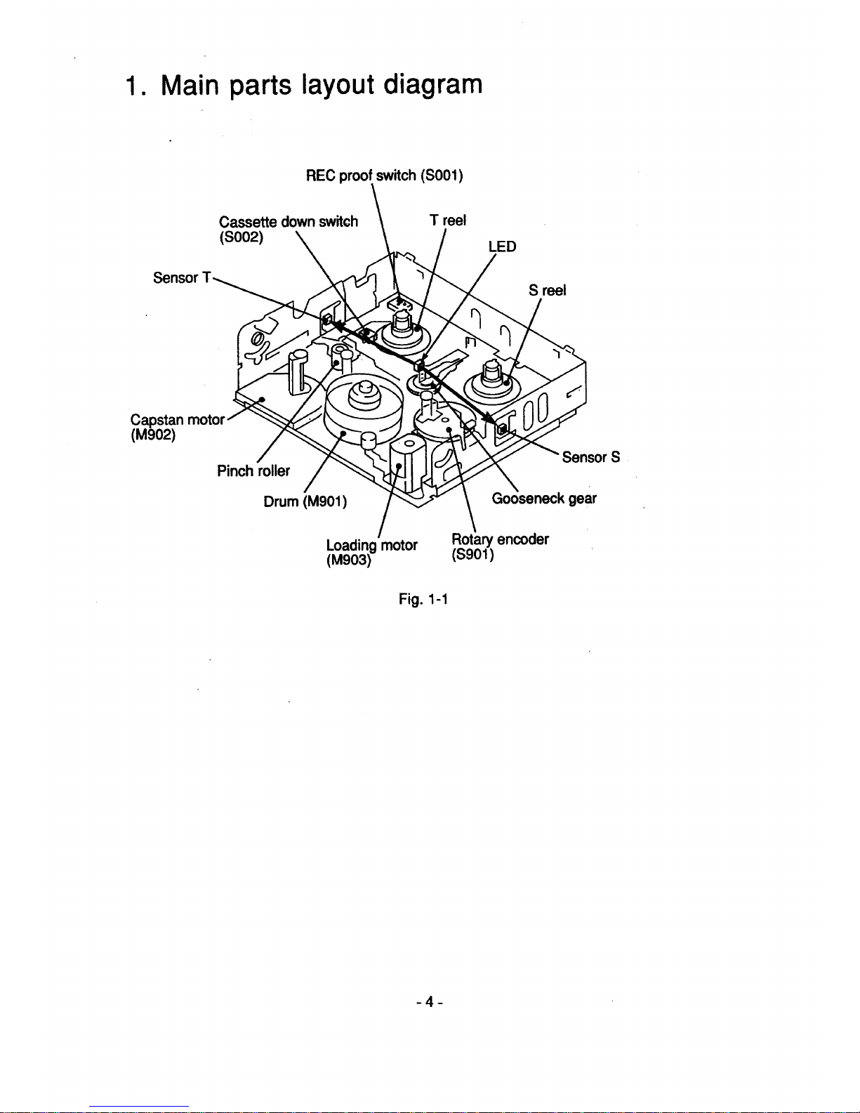
1. Main parts layout diagram
REC proof switch (S001)
Sensor
Cassette down switch
(soo2)
T reel
LED
S reel
Capstan moto
(M902)
Pinch roller
Drum (M901)
Sensor S
gear
Loading motor
(M903)
Rotary encoder
(sg01)
Fig. 1-1
-4-
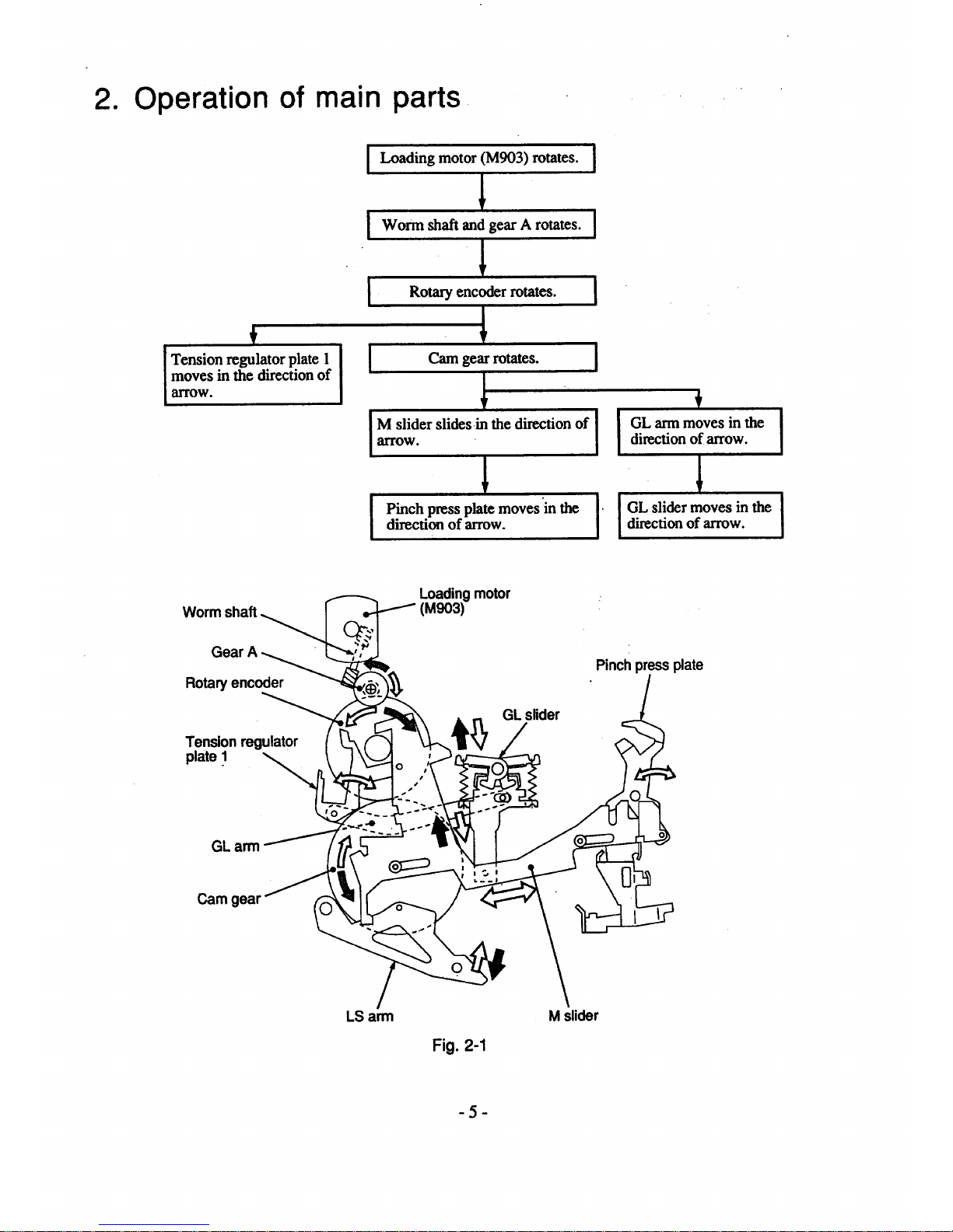
2. Operation of main parts
f
Tension regulator plate 1
moves in the direction of
arrow.
I Loading motor (M903) rotates. I
IWorm_ha_and,o__ro_os.I
] Rotary encoder rotates. I
M slider slides in the direction of I
arrow °
I
I Pinch press plate moves:in the I'
direction of arrow.
f
I GL arm moves in the
direction of arrow.
I GL slider moves in the
direction of arrow.
I
!
Loading motor
(M903)
Rotary encoder
Tension regulator
plate .1 _
GL slider
Pinch press plate
GL arm
Cam gear
LS arm
Fig. 2-1
M slider
-5-

3. Operation of each part
3-1. Driving of LS chassis
[
LS arm moves.
1
LS chassis moves. J
I
Cam gear rotates.
1
M slider moves in _)
direction after first
slightly moving in (_
direction.
Pinch press plate moves
in_)direction after first
slightly moving in(_)
direction.
I
I TG4 moves in the ]
direction of arrow.
!
TG 1 moves in the -I
direction of arrow. ]
i
V
Claws on stoppers S and T
arereleased from locked
position and guide S 0°02)
and guide T 00G3) move in
the direction of arrow. r
Pinch roller moves in the [
direction of arrow.
4
r
GL ann moves in the [
direction of arrow.
I
GL slider moves in the
direction of arrow.
I
I
Guide S (TG2) and guide
T (TG3) further move in
the direction of arrow.
-6-

GL slider _)
GL arm__ _oo_._ _ @r_,_
" ___ "" Pinch press plate
Cam gear_-iS _ __
Fig. 3-1
TG1
Guide T
(TG3)
Guide S
(TG2)
_(_uide rail
Pinchroller
arm
Stopper T
iViewed from the rear. I
Fig. 3-2 LS chassis assembly
-'7-
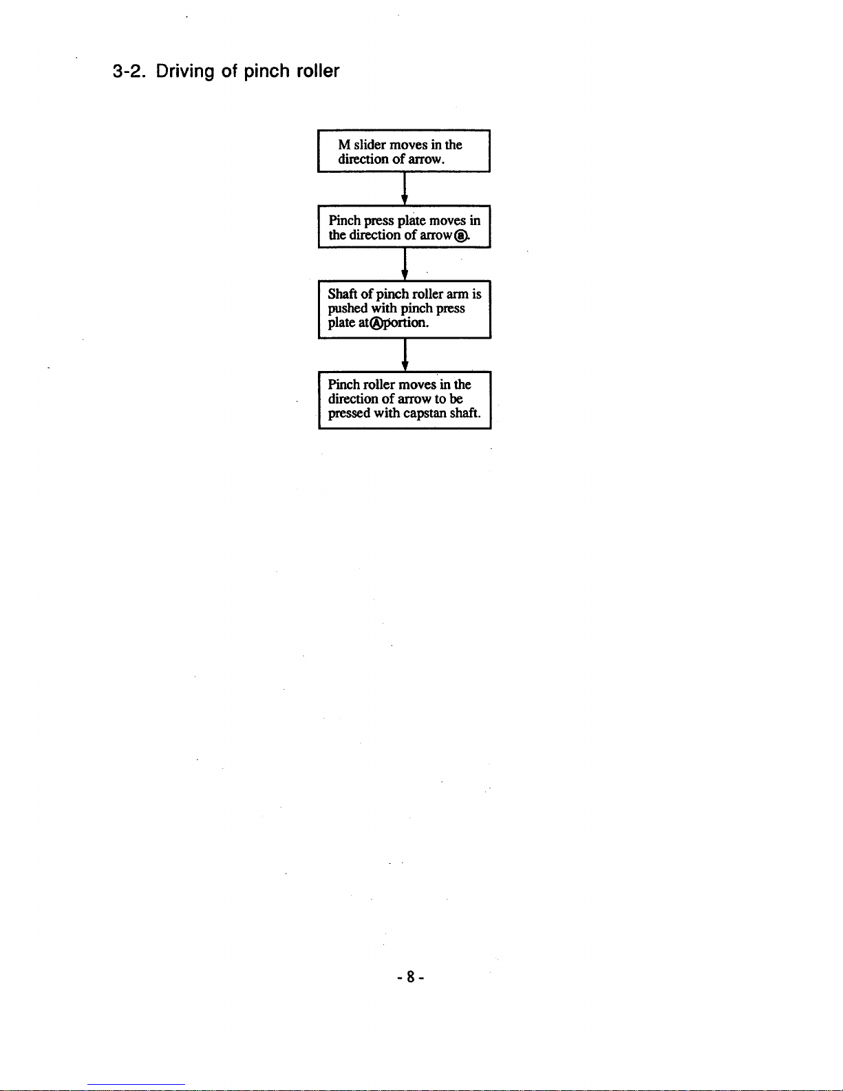
3-2. Driving of pinch roller
I
I
M slider moves in the
direction of arrow.
Pinch press plate moves in
the direction of arrow
Shaft of pinch roller arm is
pushed with pinch press
plate at(_portion.
Pinch roller moves in the
direction of arrow to be
pressed with capstan shaft.
I
-8-
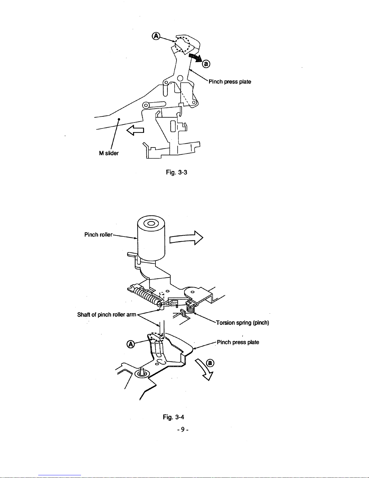
press plate
M slider
Fig. 3-3
Pinch roller_...._
Shaft of pinch
-Torsion spring(pinch)
_ Pinch press plate
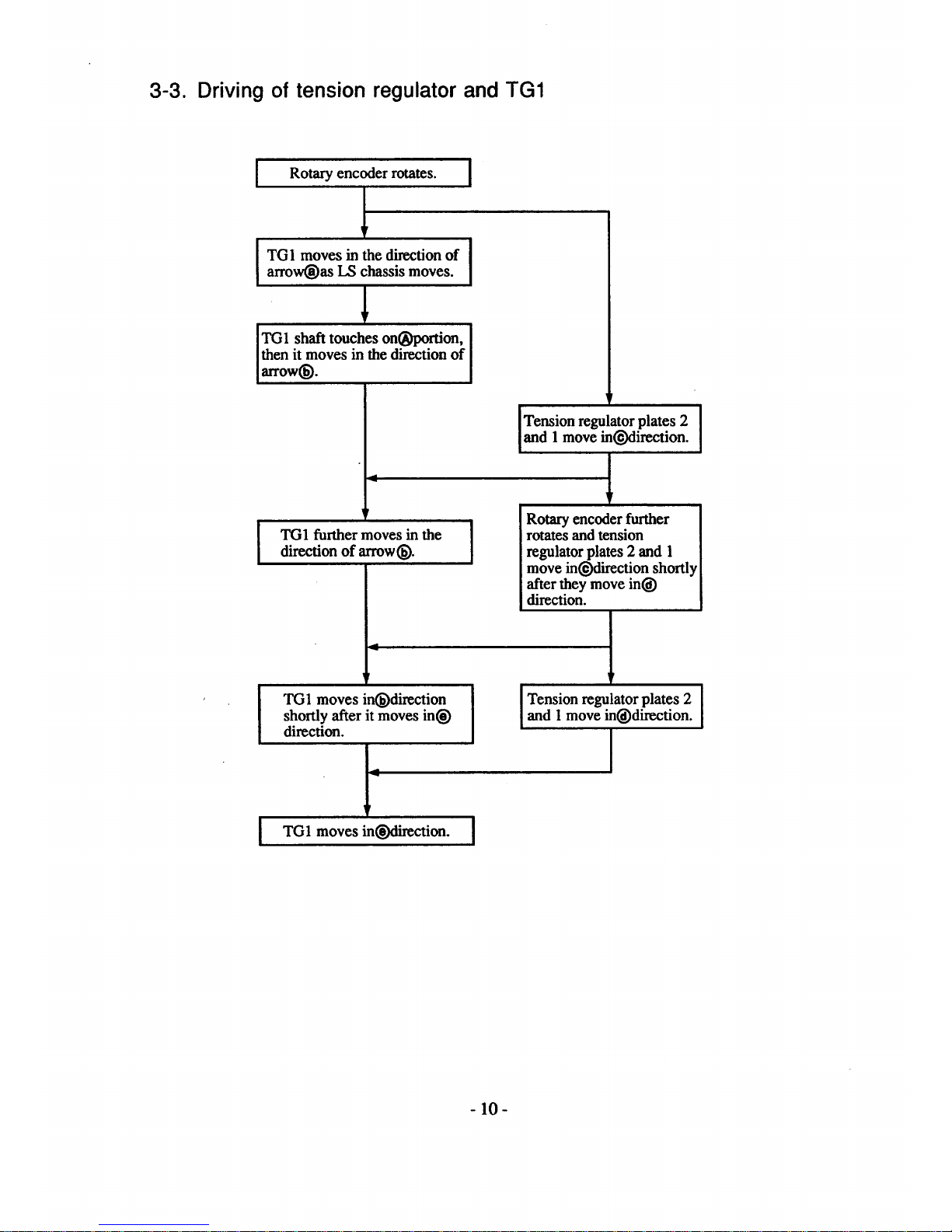
3-3. Driving of tension regulator and TG1
Rotary encoder rotates. [
1
I TG1 moves in the direction of J
|
arrow(_as LS chassis moves.
I
1
TG1 shaft touches on(_laortion. [
then it moves in the direction of I
arrow_. ]
9
!
TG1 further moves in the
dire_on of arrow_.
4
p
i
TG1 moves in(_)direction
shortly after it moves in_)
direction.
I"
TG1 moves in(_iirection.
1
!
Tension regulator plates 2
I
and 1 move in_:lirection, n
|
!
Rotary enc_ler further
rotates and tension
regulator plates 2 and 1
move inOdirection shortly
after they move ini_)
dim_ion.
p
Tension regulator plates 2
and 1 move in, direction.
I
- 10-
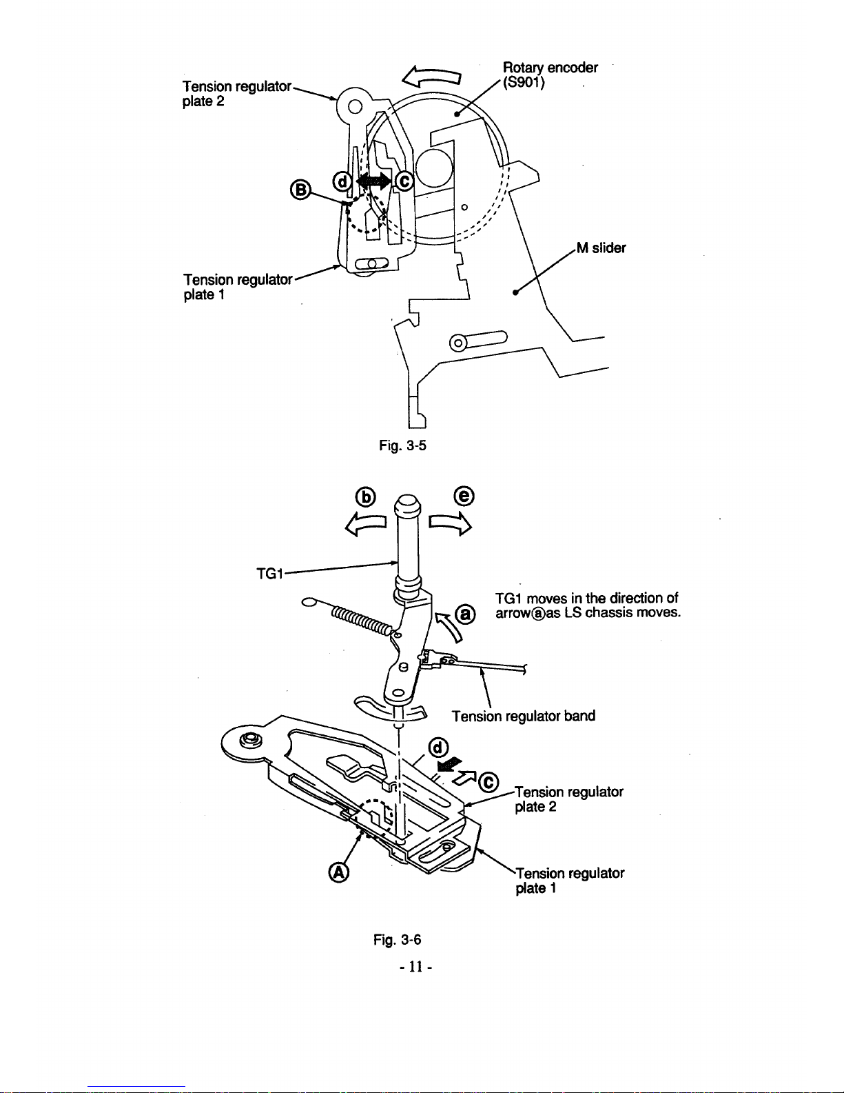
Tension regulator
plate 2
Tension regulator/
plate 1
_'- _ _Rotaryencoder
(S901)
der
Fig. 3-5
® ®
TG1
TG1 moves inthe direction of
arrow(_as LS chassis moves.
Tension regulator band
regulator
plate 2
"Tensionregulator
plate I
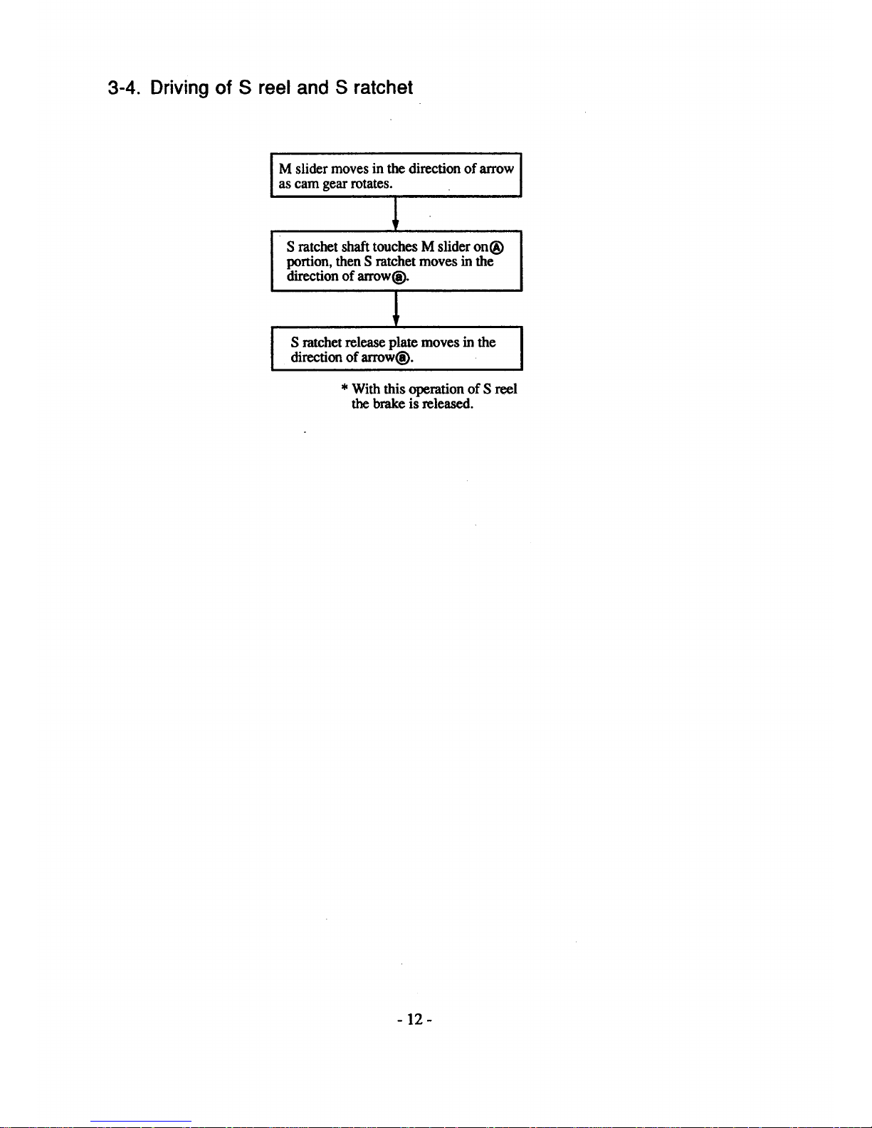
3-4. Driving of S reel and S ratchet
M slider moves in the direction of arrow I
i
as cam gear rotates.
I
S ratchet shaft touches M slider on®
portion, then S ratchet moves in the
direction of arrow(_).
S ratchetreleaseplatemoves inthe
directionof arrow_.
I
* With this operation of S reel
the brake is released.
- 12-
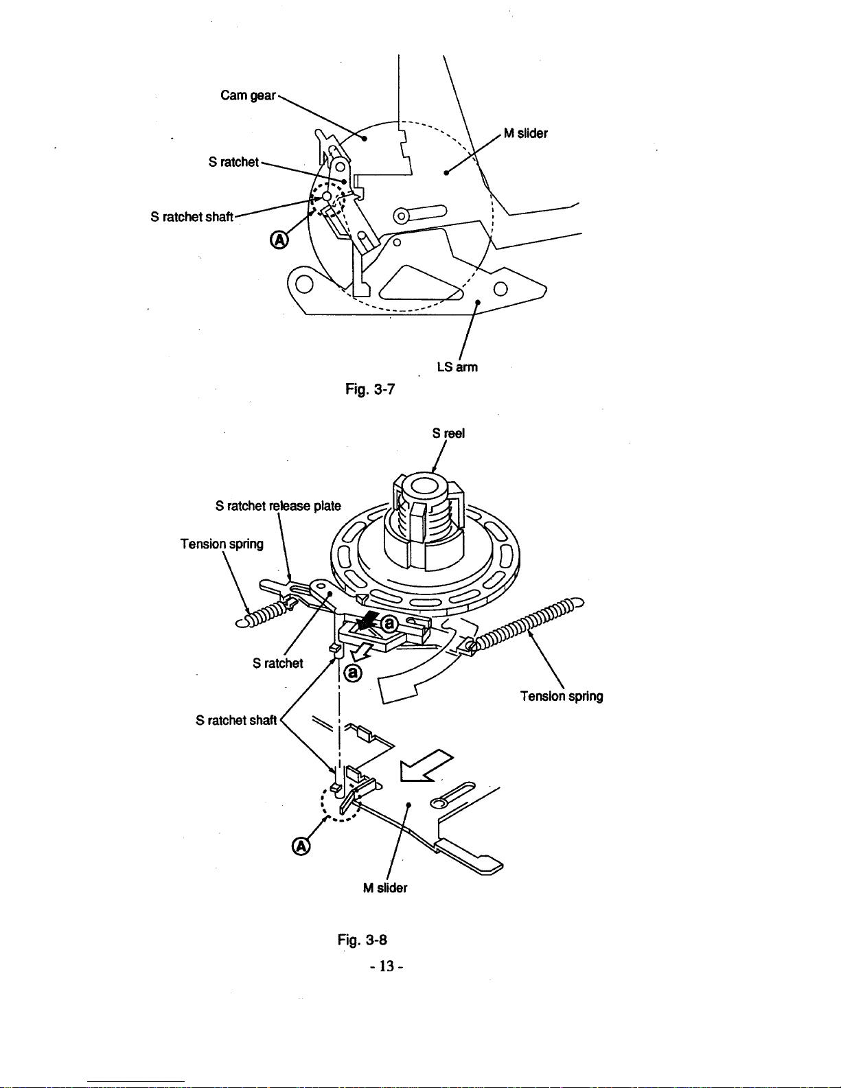
S!
S ratchet shaft
©
LSarm
S me|
S ratchetretease plate
S
S ratchet
-i'enslonspring
M slider
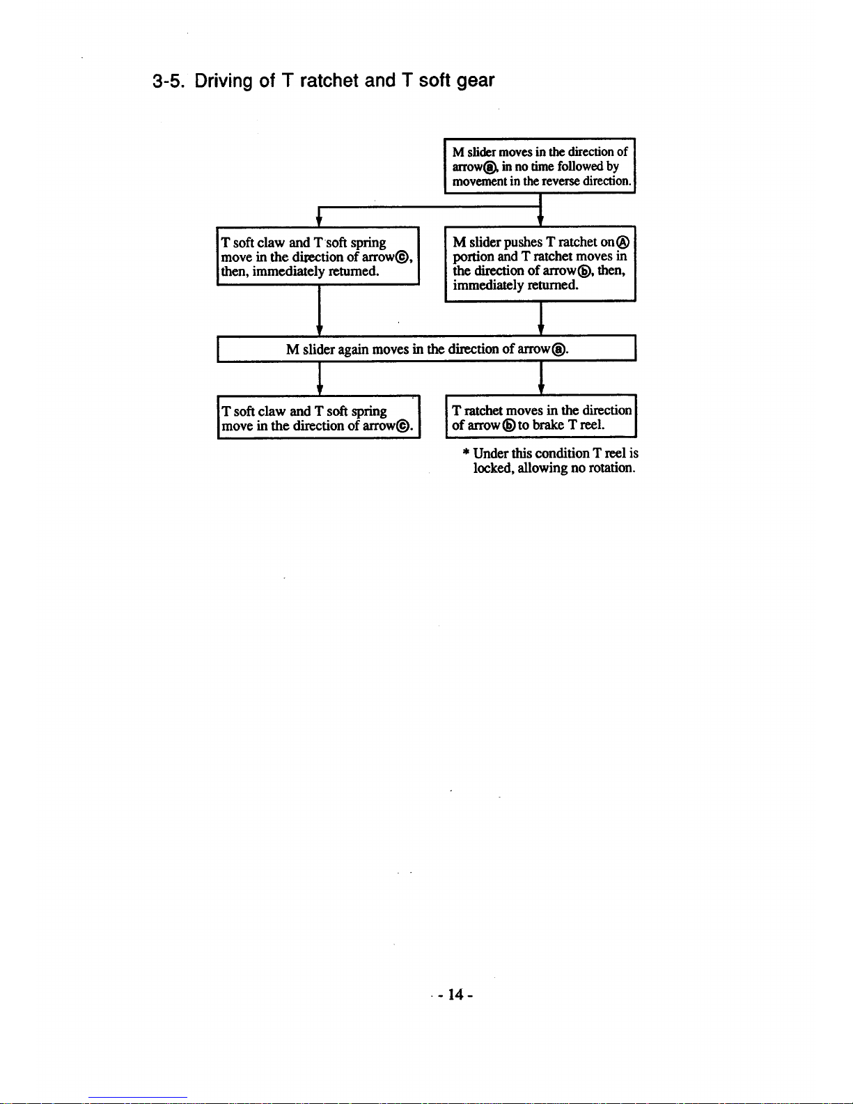
3-5. Driving of T ratchet and T soft gear
M slider moves in the direction of
arrowl_ in no time followed by
movement in thereverse direction.
+
T soft claw and T soft spring
move in the direction of arrowO,
then, immediately returned.
!
1
M slider pushes T ratchet on®
portion and T ratchet moves in
the direction of arrow_, then,
immediately returned.
1
I M slider again moves in the direction of arrow@, i
IT soft claw and T soft spring " T ratchet moves in the direction i
move in the direction of arrow_). [ [ of arrow (_)to brake T reel. I
* Under this condition T reel is
locked, allowing no rotation.
- 14-
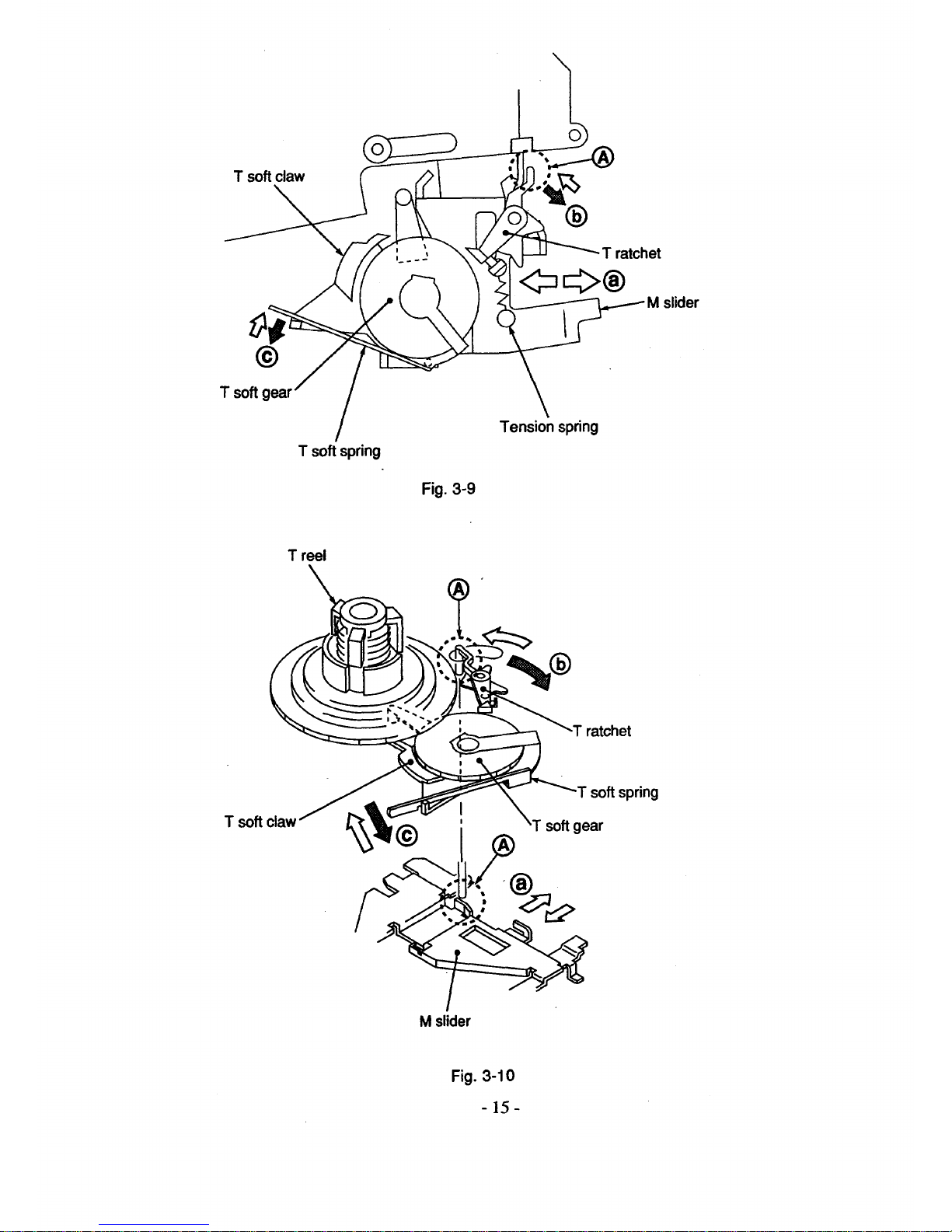
T soft claw
©
T soft gear
T soft spring
Fig. 3-9
T ratchet
slider
Tension spring
T reel
Tsoft
soft spring
softgear
M slider
 Loading...