

Page 1

ANALOG AUDIO DISTRIBUTION BOARD
BKPF-L753A
MAINTENANCE MANUAL
1st Edition (Revised 1)
Serial No. 10001 and Higher
Page 2

! WARNING
This manual is intended for qualified service personnel only.
To reduce the risk of electric shock, fire or injury, do not perform any servicing other than that
contained in the operating instructions unless you are qualified to do so. Refer all servicing to
qualified service personnel.
! WARNUNG
Die Anleitung ist nur für qualifiziertes Fachpersonal bestimmt.
Alle Wartungsarbeiten dürfen nur von qualifiziertem Fachpersonal ausgeführt werden. Um die
Gefahr eines elektrischen Schlages, Feuergefahr und Verletzungen zu vermeiden, sind bei
Wartungsarbeiten strikt die Angaben in der Anleitung zu befolgen. Andere als die angegeben
Wartungsarbeiten dürfen nur von Personen ausgeführt werden, die eine spezielle Befähigung
dazu besitzen.
! AVERTISSEMENT
Ce manual est destiné uniquement aux personnes compétentes en charge de l’entretien. Afin
de réduire les risques de décharge électrique, d’incendie ou de blessure n’effectuer que les
réparations indiquées dans le mode d’emploi à moins d’être qualifié pour en effectuer d’autres.
Pour toute réparation faire appel à une personne compétente uniquement.
BKPF-L753A
Page 3

Table of Contents
Manual Structure
Purpose of this manual ........................................................................................ 3 (E)
Contents ............................................................................................................... 3 (E)
Related manuals................................................................................................... 3 (E)
1. Service Overview
1-1. Notes on Repair Parts............................................................................1-1 (E)
1-2. IC Link Replacement ............................................................................1-1 (E)
1-3. Shield Case (S/N10001 through S/N17325) ......................................... 1-1 (E)
1-4. Name and Function of Switch/Indicator/etc. ........................................1-2 (E)
1-5. Unleaded Solder ....................................................................................1-3 (E)
2. Electrical Alignment
2-1. Electrical Alignment Overview.............................................................2-1 (E)
2-1-1. Required Equipment and Tools............................................2-1 (E)
2-1-2. Connection ...........................................................................2-1 (E)
2-2. Preparation of Adjustment ....................................................................2-2 (E)
2-3. Input/Output Gain Adjustment..............................................................2-2 (E)
2-4. CMRR (Common Mode Rejection Ratio) Adjustment.........................2-3 (E)
2-5. Input/Output Gain Adjustment for Customer Setting ...........................2-3 (E)
3. Spare Parts
ADA-55 ..................................................................................................................3-1
CN-1855/1856 ........................................................................................................3-4
DD-36 .....................................................................................................................3-4
4. Semiconductor Pin Assignments
5. Block Diagram
BKPF-L753A
Overall ....................................................................................................................5-1
1 (E)
Page 4

6. Schematic Diagrams
ADA-55 .................................................................................................................. 6-2
CN-1855/1856 ........................................................................................................ 6-3
DD-36 .....................................................................................................................6-4
7. Board Layouts
ADA-55 .................................................................................................................. 7-1
DD-36 .....................................................................................................................7-2
2 (E)
BKPF-L753A
Page 5

Purpose of this manual
Contents
Manual Structure
This manual is the maintenance manual of Analog Audio Distribution Board
BKPF-L753A.
This manual is intended for use by trained system and service engineers, and
describes the information for periodic maintenance and detailed service.
This manual is organized by following sections.
Section 1 Service Overview
This section explains the notes on repair parts and IC link replacement.
Section 2 Electrical Alignment
This section explains the adjustment after replacing part.
Section 3 Spare Parts
This section describes the spare parts.
Related manuals
Section 4 Semiconductor Pin Assignments
This section describes the pin assignments of semiconductor.
Section 5 Block Diagram
This section describes the overall block diagram.
Section 6 Schematic Diagrams
This section describes the schematic diagrams of the ADA-55, DD-36 and
CN-1855/1856 boards.
Section 7 Board Layouts
This section describes the board layouts for the ADA-55 and DD-36 boards.
The following manual is prepared for this unit.
..
. Installation Manual (Supplied with BKPF-L753A)
..
This manual describes the information on BKPF-L753A installing.
BKPF-L753A
3 (E)
Page 6

Page 7
Section 1
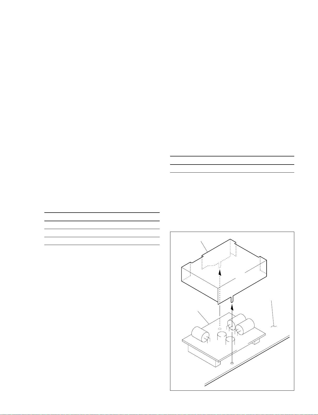
Shield case
DD-36 board
ADA-55 board
Service Overview
1-1. Notes on Repair Parts
1. Safety Related Components Warning
w
Components marked ! are critical to safe operation.
Therefore, specified parts should be used in the case of
replacement.
2. Standardization of Parts
Some repair parts supplied by Sony differ from those
used for the unit. These are because of parts commonality and improvement.
Parts list has the present standardized repair parts.
3. Stock of Parts
Parts marked with “o” at SP (Supply code) column of
the spare parts list may not be stocked. Therefore, the
delivery date will be delayed.
4. Units Representation
The following represented units are changed or
omitted in writing.
Units Representation
Capacitance uFuF
Inductance uHuH
Resistance Z Abbreviation
1-2. IC Link Replacement
w
An IC link is critical parts to safe operation.
Replace this component with Sony parts whose part
numbers appear in this manual published by Sony.
If not, this may cause a fire or electric shock.
Be sure to use the specified component in this manual.
The IC link is mounted on the ADA-55 board. Be sure to
replace with the specified IC link as shown below after
removing the foreign substances that may cause the shorts.
ADA-55 Board
Ref No. (Address) Description Part No.
PS1 (K-3) IC link 2 A !1-533-282-21
1-3. Shield Case
(S/N10001 through S/N17325)
The shield case is a component to shield the DD-36 board.
Before checking the DD-36 board, unsolder and remove
this shield case.
n
For the replacement of the ADA-55 board, please buy
BKPF-L753A because ADA-55 mounted circuit board is
not prepared for spare parts.
BKPF-L753A
1-1 (E)
Page 8
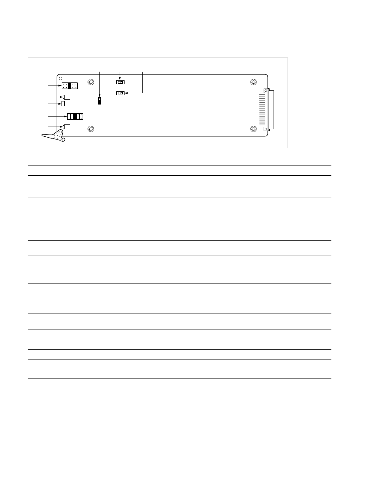
1-4. Name and Function of Switch/Indicator/etc.
1-4. Name and Function of Switch/Indicator/etc.
1
2
3
4
5
+8+40_4_8
COR2
RV4
D1
+8+40_4_8
RV3
6
COR3
COR1
MO
ST
7 8
S1
S2
Main Board (ADA-55 Board: Side A)
Switches/shorting plugs (Factory default settings are indicated by a
\\
\ mark)
\\
No. Ref. No. Name Function
7 S1 AUDIO 1 600 Z Selects the input impedance of the signal input to the AUDIO 1 connector.
OFF: 20 kZ
\ ON: 600 Z
8 S2 AUDIO 2 600 Z Selects the input impedance of the signal input to the AUDIO 2 connector.
OFF: 20 kZ
\ ON: 600 Z
4 COR1 AUDIO 2 GAIN Selects an input/output gain of the signal input to the AUDIO 2 connector.
(Valid only when COR3 is set to ST.)
+8 dB +4 dB \0 dB _4 dB _8 dB
1 COR2 AUDIO 1 GAIN Selects an input/output gain of the signal input to the AUDIO 1 connector.
+8 dB +4 dB \0 dB _4 dB _8 dB
6 COR3 MONAURAL/STEREO Selects monaural or stereo mode of the analog audio signal input/output.
MO (Monaural): The signal input to the AUDIO 1 connector is distributed to eight outputs
\ ST (Stereo): The each signal input to the AUDIO 1 and AUDIO 2 connectors is distributed to
four outputs
Indicator
No. Ref. No. Name Color Function
3 D1 POWER Green/red Green: A power supply of ±12 V is normal
Red: A power supply of ±12 V is abnormal
Gain adjusting VR
No. Ref. No. Name Function
5 RV3 AUDIO 2 FINE VR Adjusts the gain of the signal input to AUDIO 2 connector within the ±2 dB range.
2 RV4 AUDIO 1 FINE VR Adjusts the gain of the signal input to AUDIO 1 connector within the ±2 dB range.
n
At the factory-out, the gain adjusting VRs were adjusted to 0 dB. (the standard level +4 dBm)
1-2 (E)
BKPF-L753A
Page 9

1-5. Unleaded Solder
Boards requiring use of unleaded solder are printed with a
lead free mark (LF) indicating the solder contains no lead.
(Caution: Some printed circuit boards may not come
printed with the lead free mark due to their particular size.)
: LEAD FREE MARK
m
. Be sure to use the unleaded solder for the printed circuit
board printed with the lead free mark.
. The unleaded solder melts at a temperature about 40 dC
higher than the ordinary solder, therefore, it is recommended to use the soldering iron having a temperature
regulator.
. The ordinary soldering iron can be used but the iron tip
has to be applied to the solder joint for a slightly longer
time. The printed pattern (copper foil) may peel away if
the heated tip is applied for too long, so be careful.
1-5. Unleaded Solder
BKPF-L753A
1-3 (E)
Page 10

Page 11
Section 2
Electrical Alignment
2-1. Electrical Alignment Overview
2-1-1. Required Equipment and Tools
Use the equipment listed below or the equivalent.
Item Model Remarks
Extension board EX-731 (Part No. A-8322-598-A)
Audio signal generator * Tektronix SG505 (Option-02)
Audio level meter * —
Interface unit Sony PFV-L1 or PFV-L10
Adjustment screwdriver — Insulation type
Resister (600 Z , within 1 %) with lead
*: Use the equipment after calibration has been completed.
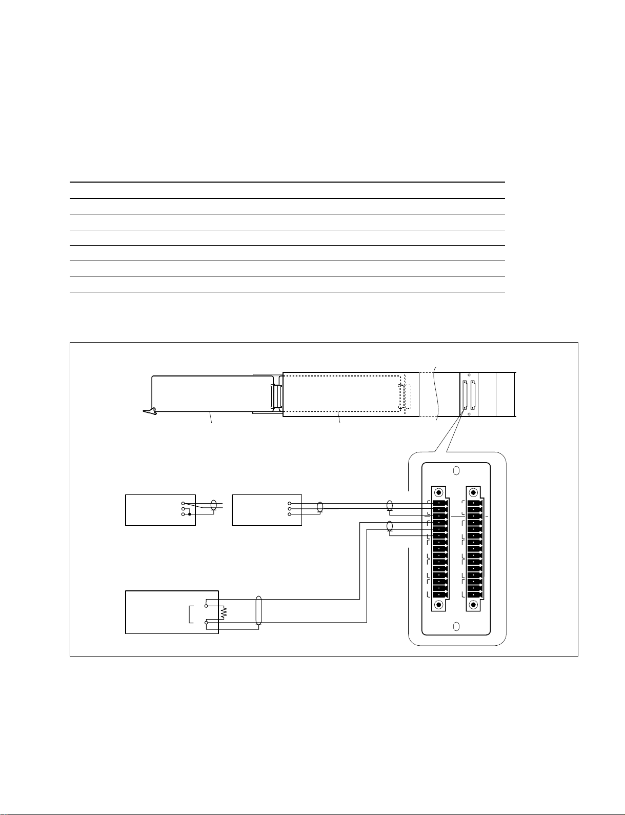
2-1-2. Connection
ADA-55 board
Analog audio signal generator
(At CMMR adj.) (At Gain adj.)
+
_
OUTPUTOUTPUT
+
_
COMCOM
Audio level mater
INPUT
+
_
600 Z
Extension board EX-731
PFV-L1/L10 (Rear)PFV-L1/L10 (Side)
BKPF-L753A
AUDIO AUDIO
12
+
_
IN
1
2
3
4
IN
G
OUT
+
_
1
G
+
_
2
G
+
_
3
G
+
_
4
G
L753A
+
_
G
+
_
G
+
_
G
+
_
G
+
_
G
BKPF-L753A
2-1 (E)
Page 12

2-2. Preparation of Adjustment
2-3. Input/Output Gain Adjustment
2-2. Preparation of Adjustment
1. Extend the ADA-55 board with a extension board.
2. Write the customer settings of the shorting plugs
(COR1, COR2, and COR3) and switches (S1, and S2)
on the ADA-55 board down in following table.
3. Set their shorting plugs and switches as follows:
Ref. No. (Address) Setting at adj. Customer setting
COR1 (A-3) 0 dB
COR2 (A-1) 0 dB
COR3 (C-2) ST (STEREO)
S1 (D-1) ON (600 Z)
S2 (D-2) ON (600 Z)
4. Turn on the power of equipment (the signal generator,
audio level meter, and interface unit PFV-L1 or
PFV-L10), and warm up them for about ten minutes.
5. Attach the 600 Z resister for termination to the audio
level meter.
+8+40_4_8
COR2
RV4
D1
+8+40_4_8
RV3
COR1
COR3
1
1
MO
ST
RV1
RV2
S1
S2
2-3. Input/Output Gain Adjustment
Measuring equipment: Audio level meter
1. Set the output of the generator to +4.0 dBm, 1 kHz.
(0 dBm = 0.775 Vrms)
CH1 adjustment
2. Connect the audio signal generator to the input of CH1
connector.
3. Connect the audio level meter to one output of CH1
connector.
4. Check that COR2 (A-1) is set to 0 dB.
If not, set it to 0 dB.
5. Adjust the CH1 output level on the audio level meter.
Adjustment point: 1RV4/ADA-55 (A-2)
Specification: 4.0 ±0.1 dBm (at 600 Z load)
CH2 adjustment
6. Connect the audio signal generator to the input of CH2
connector.
7. Connect the audio level meter to one output of CH2
connector.
8. Check that COR1 (A-3) is set to 0 dB.
If not, set it to 0 dB.
9. Adjust the CH2 output level on the audio level meter.
Adjustment point: 1RV3/ADA-55 (A-3)
Specification: 4.0 ±0.1 dBm (at 600 Z load)
2-2 (E)
ADA-55 Board (Side A)
BKPF-L753A
Page 13

2-4. CMRR (Common Mode Rejection Ratio) Adjustment
2-5. Input/Output Gain Adjustment for Customer Setting
2-4. CMRR (Common Mode Rejection
Ratio) Adjustment
Measuring equipment: Audio level meter
1. Set the output of the generator to +15.0 dBm, 60 Hz.
CH2 adjustment
2. Connect the audio signal generator to the input of CH2
connector.
3. Connect the audio level meter to one output of CH2
connector.
4. Adjust the CH2 output level on the audio level meter.
Adjustment point: 1RV2/ADA-55 (C-2)
Specification: Less than _65 dBm (at 600 Z load)
CH1 adjustment
5. Connect the audio signal generator to the input of CH1
connector.
6. Connect the audio level meter to one output of CH1
connector.
7. Adjust the CH1 output level on the audio level meter.
Adjustment point: 1RV1/ADA-55 (C-1)
Specification: Less than _65 dBm (at 600 Z load)
2-5. Input/Output Gain Adjustment for
Customer Setting
n
When the audio gain (COR1 or COR2) is not 0 dB, be sure
to perform this adjustment.
Measuring equipment: Audio level meter
1. Reset the shorting plugs (COR1 and COR2) on the
ADA-55 board to customer settings.
CH1 adjustment
2. Set the output of the generator to the customer setting
of COR1 as follows:
COR1/COR2 customer setting Output signal
_8 dB +12.0 dBm, 1 kHz
_4 dB +8.0 dBm, 1 kHz
(0 dB) (+4.0 dBm, 1 kHz)
+4 dB 0.0 dBm, 1 kHz
+8 dB _4.0 dBm, 1 kHz
(0 dBm = 0.775 Vrms)
3. Connect the audio signal generator to the input of CH1
connector.
4. Connect the audio level meter to one output of CH1
connector.
5. Adjust the CH1 output level on the audio level meter.
Adjustment point: 1RV4/ADA-55 (A-2)
Specification: 4.0 ±0.1 dBm (at 600 Z load)
CH2 adjustment
6. Set the output of the generator to the customer setting
of COR2. (Refer to table in step 2.)
7. Connect the audio signal generator to the input of CH2
connector.
8. Connect the audio level meter to one output of CH2
connector.
9. Adjust the CH2 output level on the audio level meter.
Adjustment point: 1RV3/ADA-55 (A-3)
Specification: 4.0 ±0.1 dBm (at 600 Z load)
10. After turning off the power, reset the shorting plug
(COR3) and switches (S1 and S2) on the ADA-55
board to the customer settings.
BKPF-L753A
2-3 (E)
Page 14

Page 15

Section 3
Spare Parts
-----------ADA-55 BOARD
----------- *1:[Board No. suffix -11,12]
*2:[Board No. suffix -14]
Ref. No.
or Q'ty Part No. SP Description
1pc 3-179-084-01 s LEVER (R), PC BOARD
or 3-179-085-01 s LEVER (L), PC BOARD
1pc 3-194-617-01 o HEAT SINK
1pc 3-203-115-01 o CASE, SHIELD (for DD1)
2pcs 7-685-547-14 s SCREW +BTP 3x10
8pcs 7-682-948-01 s SCREW +PSW 3x8
(ADA-55 BOARD)
Ref. No.
or Q'ty Part No. SP Description
C44 1-107-781-11 s ELECT, NONPOLAR 47uF 20% 16V
C45 1-107-781-11 s ELECT, NONPOLAR 47uF 20% 16V
C46 1-163-227-11 s CERAMIC, CHIP 10pF 5% 50V (2012)
C47 1-163-224-11 s CERAMIC, CHIP 7pF 50V (2012)
C48 1-164-346-11 s CERAMIC, CHIP 1.0uF 16V (2012)
C49 1-164-346-11 s CERAMIC, CHIP 1.0uF 16V (2012)
C50 1-163-227-11 s CERAMIC, CHIP 10pF 5% 50V (2012)
C51 1-163-224-11 s CERAMIC, CHIP 7pF 50V (2012)
C52 1-164-346-11 s CERAMIC, CHIP 1.0uF 16V (2012)
C53 1-164-346-11 s CERAMIC, CHIP 1.0uF 16V (2012)
C1 1-164-346-11 s CERAMIC, CHIP 1.0uF 16V (2012)
C2 1-126-391-11 s ELECT, CHIP 47uF 20% 6.3V
C3 1-164-346-11 s CERAMIC, CHIP 1.0uF 16V (2012)
C4 1-126-396-11 s ELECT, CHIP 47uF 20% 16V
C5 1-126-396-11 s ELECT, CHIP 47uF 20% 16V
C6 1-126-396-11 s ELECT, CHIP 47uF 20% 16V
C7 1-126-396-11 s ELECT, CHIP 47uF 20% 16V
C8 1-163-113-00 s CERAMIC, CHIP 68pF 5% 50V (2012)
C9 1-126-396-11 s ELECT, CHIP 47uF 20% 16V
C10 1-126-396-11 s ELECT, CHIP 47uF 20% 16V
C11 1-163-113-00 s CERAMIC, CHIP 68pF 5% 50V (2012)
C12 1-164-346-11 s CERAMIC, CHIP 1.0uF 16V (2012)
C13 1-164-346-11 s CERAMIC, CHIP 1.0uF 16V (2012)
C14 1-164-346-11 s CERAMIC, CHIP 1.0uF 16V (2012)
C15 1-164-346-11 s CERAMIC, CHIP 1.0uF 16V (2012)
C16 *2 1-117-681-11 s CAPACITOR, ELECT 100MF/16V
*1 1-128-397-21 s ELECT 100uF 20% 16V
C17 *2 1-117-681-11 s CAPACITOR, ELECT 100MF/16V
*1 1-128-397-21 s ELECT 100uF 20% 16V
C18 *2 1-117-681-11 s CAPACITOR, ELECT 100MF/16V
*1 1-128-397-21 s ELECT 100uF 20% 16V
C19 *2 1-117-681-11 s CAPACITOR, ELECT 100MF/16V
*1 1-128-397-21 s ELECT 100uF 20% 16V
C20 1-164-346-11 s CERAMIC, CHIP 1.0uF 16V (2012)
C21 1-164-346-11 s CERAMIC, CHIP 1.0uF 16V (2012)
C22 1-164-346-11 s CERAMIC, CHIP 1.0uF 16V (2012)
C23 1-164-346-11 s CERAMIC, CHIP 1.0uF 16V (2012)
C24 1-163-224-11 s CERAMIC, CHIP 7pF 50V (2012)
C25 1-164-346-11 s CERAMIC, CHIP 1.0uF 16V (2012)
C26 1-164-346-11 s CERAMIC, CHIP 1.0uF 16V (2012)
C27 1-126-396-11 s ELECT, CHIP 47uF 20% 16V
C28 1-126-396-11 s ELECT, CHIP 47uF 20% 16V
C29 1-163-235-11 s CERAMIC, CHIP 22pF 5% 50V (2012)
C30 1-126-396-11 s ELECT, CHIP 47uF 20% 16V
C31 1-126-396-11 s ELECT, CHIP 47uF 20% 16V
C32 1-164-346-11 s CERAMIC, CHIP 1.0uF 16V (2012)
C33 1-164-346-11 s CERAMIC, CHIP 1.0uF 16V (2012)
C34 1-126-396-11 s ELECT, CHIP 47uF 20% 16V
C35 1-126-396-11 s ELECT, CHIP 47uF 20% 16V
C36 1-163-224-11 s CERAMIC, CHIP 7pF 50V (2012)
C37 1-164-346-11 s CERAMIC, CHIP 1.0uF 16V (2012)
C38 1-164-346-11 s CERAMIC, CHIP 1.0uF 16V (2012)
C39 1-126-396-11 s ELECT, CHIP 47uF 20% 16V
C40 1-126-396-11 s ELECT, CHIP 47uF 20% 16V
C54 1-163-227-11 s CERAMIC, CHIP 10pF 5% 50V (2012)
C55 1-163-224-11 s CERAMIC, CHIP 7pF 50V (2012)
C56 1-164-346-11 s CERAMIC, CHIP 1.0uF 16V (2012)
C57 1-164-346-11 s CERAMIC, CHIP 1.0uF 16V (2012)
C58 1-163-227-11 s CERAMIC, CHIP 10pF 5% 50V (2012)
C59 1-163-224-11 s CERAMIC, CHIP 7pF 50V (2012)
C60 1-164-346-11 s CERAMIC, CHIP 1.0uF 16V (2012)
C61 1-164-346-11 s CERAMIC, CHIP 1.0uF 16V (2012)
C62 1-126-396-11 s ELECT, CHIP 47uF 20% 16V
C63 1-126-396-11 s ELECT, CHIP 47uF 20% 16V
C64 1-126-396-11 s ELECT, CHIP 47uF 20% 16V
C65 1-126-396-11 s ELECT, CHIP 47uF 20% 16V
C66 1-126-396-11 s ELECT, CHIP 47uF 20% 16V
C67 1-126-396-11 s ELECT, CHIP 47uF 20% 16V
C68 1-126-396-11 s ELECT, CHIP 47uF 20% 16V
C69 1-126-396-11 s ELECT, CHIP 47uF 20% 16V
C70 1-163-235-11 s CERAMIC, CHIP 22pF 5% 50V (2012)
C71 1-163-235-11 s CERAMIC, CHIP 22pF 5% 50V (2012)
C72 1-163-235-11 s CERAMIC, CHIP 22pF 5% 50V (2012)
C73 1-163-235-11 s CERAMIC, CHIP 22pF 5% 50V (2012)
C74 1-107-420-11 s ELECT, CHIP 47uF 20% 35V
C75 1-107-420-11 s ELECT, CHIP 47uF 20% 35V
C76 1-107-420-11 s ELECT, CHIP 47uF 20% 35V
C77 1-107-420-11 s ELECT, CHIP 47uF 20% 35V
C78 1-163-241-11 s CERAMIC, CHIP 39pF 5% 50V (2012)
C79 1-163-241-11 s CERAMIC, CHIP 39pF 5% 50V (2012)
C80 1-163-241-11 s CERAMIC, CHIP 39pF 5% 50V (2012)
C81 1-163-241-11 s CERAMIC, CHIP 39pF 5% 50V (2012)
C82 1-163-241-11 s CERAMIC, CHIP 39pF 5% 50V (2012)
C83 1-163-241-11 s CERAMIC, CHIP 39pF 5% 50V (2012)
C84 1-163-241-11 s CERAMIC, CHIP 39pF 5% 50V (2012)
C85 1-163-241-11 s CERAMIC, CHIP 39pF 5% 50V (2012)
C86 *2 1-117-681-11 s CAPACITOR, ELECT 100MF/16V
*1 1-128-397-21 s ELECT 100uF 20% 16V
C87 *2 1-117-681-11 s CAPACITOR, ELECT 100MF/16V
*1 1-128-397-21 s ELECT 100uF 20% 16V
C88 *2 1-117-681-11 s CAPACITOR, ELECT 100MF/16V
*1 1-128-397-21 s ELECT 100uF 20% 16V
C89 *2 1-117-681-11 s CAPACITOR, ELECT 100MF/16V
*1 1-128-397-21 s ELECT 100uF 20% 16V
C90 1-164-346-11 s CERAMIC, CHIP 1.0uF 16V (2012)
C91 1-164-346-11 s CERAMIC, CHIP 1.0uF 16V (2012)
C92 1-164-346-11 s CERAMIC, CHIP 1.0uF 16V (2012)
C93 1-164-346-11 s CERAMIC, CHIP 1.0uF 16V (2012)
C41 1-163-235-11 s CERAMIC, CHIP 22pF 5% 50V (2012)
C42 1-107-781-11 s ELECT, NONPOLAR 47uF 20% 16V
C43 1-107-781-11 s ELECT, NONPOLAR 47uF 20% 16V
BKPF-L753A
C94 1-164-346-11 s CERAMIC, CHIP 1.0uF 16V (2012)
C95 1-164-346-11 s CERAMIC, CHIP 1.0uF 16V (2012)
C96 1-164-346-11 s CERAMIC, CHIP 1.0uF 16V (2012)
3-1
Page 16

(ADA-55 BOARD)
(ADA-55 BOARD)
Ref. No.
or Q'ty Part No. SP Description
C97 1-164-346-11 s CERAMIC, CHIP 1.0uF 16V (2012)
C98 1-164-346-11 s CERAMIC, CHIP 1.0uF 16V (2012)
(S/N 10001 to 11870)
Ref. No.
or Q'ty Part No. SP Description
Q28 8-729-216-22 s TRANSISTOR 2SA1162-G
Q29 8-729-207-89 s TRANSISTOR 2SA1358-Y
Q30 8-729-207-82 s TRANSISTOR 2SC3421-Y
Q31 8-729-207-89 s TRANSISTOR 2SA1358-Y
CN101 1-506-746-11 s CONNECTOR, DIN 48P, MALE
COP1 1-562-579-11 s PLUG, SHORTING
COP2 1-562-579-11 s PLUG, SHORTING
COP3 1-562-579-11 s PLUG, SHORTING
Q32 8-729-207-82 s TRANSISTOR 2SC3421-Y
Q33 8-729-207-89 s TRANSISTOR 2SA1358-Y
Q34 8-729-207-82 s TRANSISTOR 2SC3421-Y
Q35 8-729-207-89 s TRANSISTOR 2SA1358-Y
Q36 8-729-207-82 s TRANSISTOR 2SC3421-Y
COR1 1-691-506-11 s CONNECTOR, 10P, MALE
Q37 8-729-425-05 s TRANSISTOR UN2221
COR2 1-691-506-11 s CONNECTOR, 10P, MALE
COR3 1-564-948-11 o CONNECTOR, 3P, MALE
R1 1-216-639-11 s METAL, CHIP 330 0.5% 1/10W (2012)
R2 1-216-623-11 s METAL, CHIP 68 0.5% 1/10W (2012)
D1 8-719-027-84 s LED CL-155UR/G-D, RED/GRN
R3 1-216-639-11 s METAL, CHIP 330 0.5% 1/10W (2012)
R4 1-216-623-11 s METAL, CHIP 68 0.5% 1/10W (2012)
DD36 *2 1-475-611-11 s CONVERTER UNIT, DC-DC
IC1 8-759-700-96 s IC NJM5534M
IC2 8-759-700-96 s IC NJM5534M
IC3 8-759-700-96 s IC NJM5534M
IC4 8-759-700-96 s IC NJM5534M
IC5 8-759-700-96 s IC NJM5534M
IC6 8-759-700-96 s IC NJM5534M
IC7 8-759-700-96 s IC NJM5534M
IC8 8-759-700-96 s IC NJM5534M
IC9 8-759-700-96 s IC NJM5534M
IC10 8-759-700-96 s IC NJM5534M
R5 1-216-687-11 s METAL, CHIP 33K 0.5% 1/10W (2012)
R6 1-216-687-11 s METAL, CHIP 33K 0.5% 1/10W (2012)
R7 1-216-679-11 s METAL, CHIP 15K 0.5% 1/10W (2012)
R8 1-216-635-11 s METAL, CHIP 220 0.5% 1/10W (2012)
R9 1-216-651-11 s METAL, CHIP 1.0K 0.5% 1/10W (2012)
R10 1-216-635-11 s METAL, CHIP 220 0.5% 1/10W (2012)
R11 1-216-678-11 s METAL, CHIP 13K 0.5% 1/10W (2012)
R12 1-216-679-11 s METAL, CHIP 15K 0.5% 1/10W (2012)
R13 1-216-675-11 s METAL, CHIP 10K 0.5% 1/10W (2012)
R14 1-216-675-11 s METAL, CHIP 10K 0.5% 1/10W (2012)
R15 1-218-367-11 s METAL, CHIP 10K 0.1% 1/16W (2012)
IC11 8-759-990-63 s IC PCF8574AT
(S/N 10001 to 11870)
R16 1-218-367-11 s METAL, CHIP 10K 0.1% 1/16W (2012)
R17 1-218-367-11 s METAL, CHIP 10K 0.1% 1/16W (2012)
R18 1-218-367-11 s METAL, CHIP 10K 0.1% 1/16W (2012)
L1 1-424-643-11 s COIL, CHOKE 10uH
L2 1-424-643-11 s COIL, CHOKE 10uH
R19 1-218-366-11 s METAL, CHIP 3.3K 0.1% 1/10W (2012)
R20 1-218-366-11 s METAL, CHIP 3.3K 0.1% 1/10W (2012)
L3 1-424-643-11 s COIL, CHOKE 10uH
R21 1-216-659-11 s METAL, CHIP 2.2K 0.5% 1/10W (2012)
PS1 ! 1-533-282-21 s LINK, IC, CHIP 2A
R22 1-218-366-11 s METAL, CHIP 3.3K 0.1% 1/10W (2012)
R23 1-218-366-11 s METAL, CHIP 3.3K 0.1% 1/10W (2012)
Q1 8-729-120-28 s TRANSISTOR 2SC1623-L5L6
Q2 8-729-120-28 s TRANSISTOR 2SC1623-L5L6
R24 1-216-659-11 s METAL, CHIP 2.2K 0.5% 1/10W (2012)
R25 1-216-651-11 s METAL, CHIP 1.0K 0.5% 1/10W (2012)
Q3 8-729-216-22 s TRANSISTOR 2SA1162-G
Q4 8-729-120-28 s TRANSISTOR 2SC1623-L5L6
Q5 8-729-120-28 s TRANSISTOR 2SC1623-L5L6
R26 1-216-619-11 s METAL, CHIP 47 0.5% 1/10W (2012)
R27 1-216-619-11 s METAL, CHIP 47 0.5% 1/10W (2012)
R28 1-216-619-11 s METAL, CHIP 47 0.5% 1/10W (2012)
Q6 8-729-216-22 s TRANSISTOR 2SA1162-G
Q7 8-729-120-28 s TRANSISTOR 2SC1623-L5L6
R29 1-216-619-11 s METAL, CHIP 47 0.5% 1/10W (2012)
R30 1-216-659-11 s METAL, CHIP 2.2K 0.5% 1/10W (2012)
Q8 8-729-216-22 s TRANSISTOR 2SA1162-G
Q9 8-729-120-28 s TRANSISTOR 2SC1623-L5L6
Q10 8-729-216-22 s TRANSISTOR 2SA1162-G
R31 1-216-659-11 s METAL, CHIP 2.2K 0.5% 1/10W (2012)
R32 1-216-603-11 s METAL, CHIP 10 0.5% 1/10W (2012)
R33 1-216-603-11 s METAL, CHIP 10 0.5% 1/10W (2012)
Q11 8-729-120-28 s TRANSISTOR 2SC1623-L5L6
Q12 8-729-216-22 s TRANSISTOR 2SA1162-G
R34 1-216-669-11 s METAL, CHIP 5.6K 0.5% 1/10W (2012)
R35 1-216-669-11 s METAL, CHIP 5.6K 0.5% 1/10W (2012)
Q13 8-729-120-28 s TRANSISTOR 2SC1623-L5L6
Q14 8-729-216-22 s TRANSISTOR 2SA1162-G
Q15 8-729-120-28 s TRANSISTOR 2SC1623-L5L6
R36 1-216-686-11 s METAL, CHIP 30K 0.5% 1/10W (2012)
R37 1-216-682-11 s METAL, CHIP 20K 0.5% 1/10W (2012)
R38 1-216-677-11 s METAL, CHIP 12K 0.5% 1/10W (2012)
Q16 8-729-216-22 s TRANSISTOR 2SA1162-G
Q17 8-729-120-28 s TRANSISTOR 2SC1623-L5L6
R39 1-216-668-11 s METAL, CHIP 5.1K 0.5% 1/10W (2012)
R40 1-216-668-11 s METAL, CHIP 5.1K 0.5% 1/10W (2012)
Q18 8-729-216-22 s TRANSISTOR 2SA1162-G
Q19 8-729-120-28 s TRANSISTOR 2SC1623-L5L6
Q20 8-729-216-22 s TRANSISTOR 2SA1162-G
R41 1-216-663-11 s METAL, CHIP 3.3K 0.5% 1/10W (2012)
R42 1-216-655-11 s METAL, CHIP 1.5K 0.5% 1/10W (2012)
R43 1-216-686-11 s METAL, CHIP 30K 0.5% 1/10W (2012)
Q21 8-729-120-28 s TRANSISTOR 2SC1623-L5L6
Q22 8-729-216-22 s TRANSISTOR 2SA1162-G
R44 1-216-682-11 s METAL, CHIP 20K 0.5% 1/10W (2012)
R45 1-216-677-11 s METAL, CHIP 12K 0.5% 1/10W (2012)
Q23 8-729-120-28 s TRANSISTOR 2SC1623-L5L6
Q24 8-729-216-22 s TRANSISTOR 2SA1162-G
Q25 8-729-120-28 s TRANSISTOR 2SC1623-L5L6
R46 1-216-668-11 s METAL, CHIP 5.1K 0.5% 1/10W (2012)
R47 1-216-668-11 s METAL, CHIP 5.1K 0.5% 1/10W (2012)
R48 1-216-611-11 s METAL, CHIP 22 0.5% 1/10W (2012)
Q26 8-729-216-22 s TRANSISTOR 2SA1162-G
Q27 8-729-120-28 s TRANSISTOR 2SC1623-L5L6
R49 1-216-611-11 s METAL, CHIP 22 0.5% 1/10W (2012)
R50 1-216-662-11 s METAL, CHIP 3.0K 0.5% 1/10W (2012)
3-2
BKPF-L753A
Page 17

(ADA-55 BOARD)
(ADA-55 BOARD)
Ref. No.
or Q'ty Part No. SP Description
R51 1-216-662-11 s METAL, CHIP 3.0K 0.5% 1/10W (2012)
R52 1-216-611-11 s METAL, CHIP 22 0.5% 1/10W (2012)
R53 1-216-611-11 s METAL, CHIP 22 0.5% 1/10W (2012)
R54 1-216-663-11 s METAL, CHIP 3.3K 0.5% 1/10W (2012)
R55 1-216-667-11 s METAL, CHIP 4.7K 0.5% 1/10W (2012)
R56 1-216-611-11 s METAL, CHIP 22 0.5% 1/10W (2012)
R57 1-216-611-11 s METAL, CHIP 22 0.5% 1/10W (2012)
R58 1-216-655-11 s METAL, CHIP 1.5K 0.5% 1/10W (2012)
R59 1-216-662-11 s METAL, CHIP 3.0K 0.5% 1/10W (2012)
R60 1-216-662-11 s METAL, CHIP 3.0K 0.5% 1/10W (2012)
R61 1-216-611-11 s METAL, CHIP 22 0.5% 1/10W (2012)
R62 1-216-611-11 s METAL, CHIP 22 0.5% 1/10W (2012)
R63 1-216-667-11 s METAL, CHIP 4.7K 0.5% 1/10W (2012)
R64 1-216-662-11 s METAL, CHIP 3.0K 0.5% 1/10W (2012)
R65 1-216-662-11 s METAL, CHIP 3.0K 0.5% 1/10W (2012)
R66 1-216-662-11 s METAL, CHIP 3.0K 0.5% 1/10W (2012)
R67 1-216-662-11 s METAL, CHIP 3.0K 0.5% 1/10W (2012)
R68 1-216-611-11 s METAL, CHIP 22 0.5% 1/10W (2012)
R69 1-216-611-11 s METAL, CHIP 22 0.5% 1/10W (2012)
R70 1-216-611-11 s METAL, CHIP 22 0.5% 1/10W (2012)
R71 1-216-611-11 s METAL, CHIP 22 0.5% 1/10W (2012)
R72 1-216-611-11 s METAL, CHIP 22 0.5% 1/10W (2012)
R73 1-216-611-11 s METAL, CHIP 22 0.5% 1/10W (2012)
R74 1-216-611-11 s METAL, CHIP 22 0.5% 1/10W (2012)
R75 1-216-611-11 s METAL, CHIP 22 0.5% 1/10W (2012)
Ref. No.
or Q'ty Part No. SP Description
R111 1-216-308-00 s METAL, CHIP 4.7 5% 1/10W (2012)
R112 1-216-308-00 s METAL, CHIP 4.7 5% 1/10W (2012)
R113 1-216-308-00 s METAL, CHIP 4.7 5% 1/10W (2012)
R114 1-216-308-00 s METAL, CHIP 4.7 5% 1/10W (2012)
R115 1-216-308-00 s METAL, CHIP 4.7 5% 1/10W (2012)
R116 1-216-308-00 s METAL, CHIP 4.7 5% 1/10W (2012)
R117 1-216-308-00 s METAL, CHIP 4.7 5% 1/10W (2012)
R118 1-216-308-00 s METAL, CHIP 4.7 5% 1/10W (2012)
R119 1-216-308-00 s METAL, CHIP 4.7 5% 1/10W (2012)
R120 1-216-308-00 s METAL, CHIP 4.7 5% 1/10W (2012)
R121 1-216-308-00 s METAL, CHIP 4.7 5% 1/10W (2012)
R122 1-216-308-00 s METAL, CHIP 4.7 5% 1/10W (2012)
R123 1-216-308-00 s METAL, CHIP 4.7 5% 1/10W (2012)
R140 1-216-639-11 s METAL, CHIP 330 0.5% 1/10W (2012)
R141 1-216-662-11 s METAL, CHIP 3.0K 0.5% 1/10W (2012)
R142 1-216-603-11 s METAL, CHIP 10 0.5% 1/10W (2012)
R143 1-216-639-11 s METAL, CHIP 330 0.5% 1/10W (2012)
R144 1-216-662-11 s METAL, CHIP 3.0K 0.5% 1/10W (2012)
R145 1-216-603-11 s METAL, CHIP 10 0.5% 1/10W (2012)
R146 1-216-649-11 s METAL, CHIP 820 0.5% 1/10W (2012)
R147 1-216-649-11 s METAL, CHIP 820 0.5% 1/10W (2012)
R148 1-216-699-11 s METAL, CHIP 100K 0.5% 1/10W (2012)
R149 1-216-699-11 s METAL, CHIP 100K 0.5% 1/10W (2012)
(S/N 10001 to 11870)
R201 1-216-615-11 s METAL, CHIP 33 0.5% 1/10W (2012)
(S/N 10001 to 10290)
R76 1-216-662-11 s METAL, CHIP 3.0K 0.5% 1/10W (2012)
R77 1-216-662-11 s METAL, CHIP 3.0K 0.5% 1/10W (2012)
R202 1-216-615-11 s METAL, CHIP 33 0.5% 1/10W (2012)
(S/N 10001 to 10290)
R78 1-216-662-11 s METAL, CHIP 3.0K 0.5% 1/10W (2012)
R79 1-216-662-11 s METAL, CHIP 3.0K 0.5% 1/10W (2012)
R80 1-216-655-11 s METAL, CHIP 1.5K 0.5% 1/10W (2012)
RB2 1-236-907-11 s RES, NETWORK, CHIP 100Kx4 (3216)
(S/N 10001 to 11870)
R81 1-216-655-11 s METAL, CHIP 1.5K 0.5% 1/10W (2012)
R82 1-216-655-11 s METAL, CHIP 1.5K 0.5% 1/10W (2012)
R83 1-216-655-11 s METAL, CHIP 1.5K 0.5% 1/10W (2012)
R84 1-216-629-11 s METAL, CHIP 120 0.5% 1/10W (2012)
R85 1-216-629-11 s METAL, CHIP 120 0.5% 1/10W (2012)
RV1 1-227-144-21 s RES, ADJ, 50
(S/N 10291 and Higher)
1-237-028-11 s RES, ADJ, CERMET 20
(S/N 10001 to 10290)
RV2 1-227-144-21 s RES, ADJ, 50
(S/N 10291 and Higher)
R86 1-216-629-11 s METAL, CHIP 120 0.5% 1/10W (2012)
R87 1-216-629-11 s METAL, CHIP 120 0.5% 1/10W (2012)
R88 1-216-681-11 s METAL, CHIP 18K 0.5% 1/10W (2012)
R89 1-216-681-11 s METAL, CHIP 18K 0.5% 1/10W (2012)
1-237-028-11 s RES, ADJ, CERMET 20
(S/N 10001 to 10290)
RV3 1-230-749-21 s RES, ADJ, CERMET 5K
RV4 1-230-749-21 s RES, ADJ, CERMET 5K
R90 1-216-681-11 s METAL, CHIP 18K 0.5% 1/10W (2012)
S1 *2 1-771-709-31 s SWITCH, SLIDE
R91 1-216-681-11 s METAL, CHIP 18K 0.5% 1/10W (2012)
R92 1-216-681-11 s METAL, CHIP 18K 0.5% 1/10W (2012)
R93 1-216-681-11 s METAL, CHIP 18K 0.5% 1/10W (2012)
*1 1-553-977-00 s SWITCH, SLIDE
S2 *2 1-771-709-31 s SWITCH, SLIDE
*1 1-553-977-00 s SWITCH, SLIDE
R94 1-216-681-11 s METAL, CHIP 18K 0.5% 1/10W (2012)
R95 1-216-681-11 s METAL, CHIP 18K 0.5% 1/10W (2012)
R96 1-216-298-00 s METAL, CHIP 2.2 5% 1/10W (2012)
R97 1-216-298-00 s METAL, CHIP 2.2 5% 1/10W (2012)
R98 1-216-298-00 s METAL, CHIP 2.2 5% 1/10W (2012)
R99 1-216-298-00 s METAL, CHIP 2.2 5% 1/10W (2012)
R100 1-216-651-11 s METAL, CHIP 1.0K 0.5% 1/10W (2012)
R101 1-216-651-11 s METAL, CHIP 1.0K 0.5% 1/10W (2012)
R102 1-216-651-11 s METAL, CHIP 1.0K 0.5% 1/10W (2012)
R103 1-216-651-11 s METAL, CHIP 1.0K 0.5% 1/10W (2012)
R104 1-216-651-11 s METAL, CHIP 1.0K 0.5% 1/10W (2012)
R105 1-216-651-11 s METAL, CHIP 1.0K 0.5% 1/10W (2012)
R106 1-216-651-11 s METAL, CHIP 1.0K 0.5% 1/10W (2012)
R107 1-216-651-11 s METAL, CHIP 1.0K 0.5% 1/10W (2012)
R108 1-216-308-00 s METAL, CHIP 4.7 5% 1/10W (2012)
R109 1-216-308-00 s METAL, CHIP 4.7 5% 1/10W (2012)
R110 1-216-308-00 s METAL, CHIP 4.7 5% 1/10W (2012)
BKPF-L753A
3-3
Page 18

-----------------CN-1855/1856 BOARD
------------------
-----------------------------------DD-36 BOARD ;For S/N 10001-S/N 17325
----------------------------------- Ref. No.
or Q'ty Part No. SP Description
*1:[Board No. suffix -11]
*2:[Board No. suffix -12]
1pc 3-202-610-02 o PANEL (753A), CN
2pcs 3-686-054-02 o STUD, SUPPORT, PC BOARD
4pcs 7-621-775-10 s SCREW +B 2.6x4
Ref. No.
or Q'ty Part No. SP Description
2pcs 7-688-002-11 s WASHER 2.6, MIDDLE
1pc A-8322-755-A o MOUNTED CIRCUIT BOARD, DD-36
The components in the connector panel assembly of
BKPF-L753A are out of spare parts except above.
When component replacement (except above) is required,
replace by assembly (including CN-1855/1856 mounted
circuit boards) below.
C1 1-115-339-11 s CERAMIC, CHIP 0.1uF 10% 50V (2012)
C2 1-164-182-11 s CERAMIC, CHIP 0.033uF 10% 50V(2012)
C3 1-126-394-11 s ELECT, CHIP 10uF 20% 16V
C4 1-109-982-11 s CERAMIC, CHIP 1.0uF 10% 10V (2012)
C5 1-164-182-11 s CERAMIC, CHIP 0.033uF 10% 50V(2012)
A-8322-760-A o CN PANEL (753A) ASSY
C6 1-109-982-11 s CERAMIC, CHIP 1.0uF 10% 10V (2012)
C7 1-109-982-11 s CERAMIC, CHIP 1.0uF 10% 10V (2012)
C8 1-127-518-11 s ALUMN SOLID 100uF 20% 16V
C10 1-127-518-11 s ALUMN SOLID 100uF 20% 16V
C11 1-127-518-11 s ALUMN SOLID 100uF 20% 16V
C13 1-115-339-11 s CERAMIC, CHIP 0.1uF 10% 50V (2012)
CN1 1-793-560-11 o CONNECTOR, PC BOARD, 7P, MALE
CN2 1-793-561-11 o CONNECTOR, PC BOARD, 9P, MALE
D1 8-719-065-59 s DIODE MBR0530T1
D2 8-719-065-59 s DIODE MBR0530T1
D3 8-719-065-59 s DIODE MBR0530T1
D4 8-719-065-59 s DIODE MBR0530T1
IC1 8-759-466-72 s IC MAX742CWP
L1 1-469-541-11 s COIL, CHOKE 47uH
L2 1-469-541-11 s COIL, CHOKE 47uH
Q1 8-729-045-16 s TRANSISTOR SI4410DY
Q2 8-729-045-53 s TRANSISTOR SI4431DY
R1 *2 1-208-758-11 s RESISTOR,CHIP 100 1/10W (2012)
*1 1-216-627-11 s METAL, CHIP 100 0.5% 1/10W (2012)
R2 1-219-706-11 s METAL, CHIP 0.1 1% 1W (6432)
R3 1-219-706-11 s METAL, CHIP 0.1 1% 1W (6432)
3-4
BKPF-L753A
Page 19

Section 4
Semiconductor Pin Assignments
Semiconductors of which functions are equivalent are described
here. For parts replacement, refer to the section of Spare Parts in
this manual. The circuit diagram of each IC is obtained from the
IC data book published by the manufacturer.
IC
Index
DIODE Page LED Page
MBR0530T1 ..................... 4-2
CL-155UR/G-D ................ 4-2 2SA1162G ....................... 4-2
TRANSISTOR Page IC Page
MAX742CWP-TE2 ........... 4-3
2SA1358-Y....................... 4-2
2SA812-T1-M5M6............ 4-2
2SC1623 .......................... 4-2
2SC1623-T1-L5L6 ........... 4-2
2SC3421-Y ...................... 4-2
SI4410DY-T1-REVA ......... 4-2
SI4431DY-T1 .................... 4-2
UN2221 ............................ 4-2
UN2221-TX ...................... 4-2
NJM5534M....................... 4-3
NJM5534M(TE2).............. 4-3
PCF8574AT...................... 4-3
BKPF-L753A
4-1
Page 20

IC
Diode, LED, Transistor
DIODE
—TOP VIEW—
MBR0530T1
LED TRANSISTOR
—TOP VIEW—
CL-155UR/G-D 2SA1162G
2SA812-T1-M5M6
RED
GREEN
2SA1358-Y
—TOP VIEW—
2SC1623
2SC1623-T1-L5L6
8
7
1
2
3
S
4
687
5
—TOP VIEW—
R1
R2
SI4431DY-T1
6
5
4
321
UN2221
(R1=2.2k,R2=2.2k)
UN2221-TX
2SC3421-Y
SI4410DY-T1-REVA
8
7
1
6
2
5
3
4
D
D4D
D
687
5
G
2
1
3
S
S
S
4-2
BKPF-L753A
Page 21

IC
IC
MAX742CWP-TE2 (MAXIM)
DUAL-OUTPUT, SWITCH-MODE REGURATOR
—TOP VIEW—
INPUT
12/
15
100/
AV+
CC_
CC+
CSH_
CSH+
CSL_
CSL+
FB_
FB+
PDRV
SS
V+
OUTPUT
EXT_
EXT+
VREF
∑
PULSE
PAMP
SQUARE
∑
200
OSC
100/
A-GND
VREF
12/
FB+
CC+
AV+
12/
VREF
CC_
FB_
FB+
15
FB_
GND
20
19
18
17
16
15
14
13
12
11
CC+
2
SELECT
9
CC_
CSH+
CSL+
EXT+
PUMP
PDRV_
EXT_
V+
CSH_
CSL_
+
_
12/
+
_
15
1
2
3
A-GND
4
5
200
6
15
7
SS
8
9
10
1
3
7
VREF
6
10
NJM5534M (JRC)
NJM5534M(TE2)
OPERATINAL AMPLIFIER
—TOP VIEW—
VCC
COMPENSATE
8
/BALANCE
7
6
5
COMPENSATE
BALANCE
1
_
2
+
3
V
EE
4
: SELECTS VOUTS (±15 V/±12 V)
: SELECTS OSC FREQUENCY (200 kHz/100 kHz)
: ANALOG SUPPLY VOLTAGE INPUT (+5 V)
: INVERTING COMPENSATION CAPACITOR
: STEP-UP COMPENSATION CAPACITOR
: CURRENT SENSE HIGH (INVERTING SECTION)
: CURRENT SENSE HIGH (STEP-UP SECTION)
: CURRENT SENSE LOW (INVERTING SECTION)
: CURRENT SENSE LOW (STEP-UP SECTION)
: INVERTING SECTION FEEDBACK INPUT
: STEP-UP FEEDBACK INPUT
: VOLTAGE INPUT
: SOFT-START TIMING CAPACITOR
: HIGH-CURRENT SUPPLY VOLTAGE INPUT (+5 V)
: PUSH-PULL OUTPUT
: PUSH-PULL OUTPUT
: REFERENCE VOLTAGE OUTPUT
100/
AV+
200
5
4
SOFT-START
AND
THERMAL
SHUTDOWN
QR
S
S
R
Q
20
CSH+
19
CSL+
13
V+
17
EXT+
18
GND
8
SS
16
PUMP
14
EXT_
15
PDRV
12
CSH_
11
CSL_
PCF8574AT (PHILIPS)
C-MOS REMOTE 8-BIT I/O EXPANDER
—TOP VIEW—
1
SDA
SCL
INT
P7
P6 I/O
P5 I/O
P4 I/O
I/O
PCF8574
PCF8574A
2
3
14
SHIFT
REGISTER
write pulse
read pulse
1
A0 IN
A1 IN
2
A2 IN
3
P0 I/O
4
P1 I/O
5
P2 I/O
6
P3 I/O
7
GND
8
INPUT
A0 - A2
; ADDRESS INPUTS
SCL
; SYSTEM CLOCK LINE
OUTPUT
INT
; INTERRUPT OUTPUT
SDA
; SERIAL DATA LINE
INPUT/OUTPUT
P0 - P7
; 8-BIT QUASI-BIDIRECTIONAL I/O PORT
13
INT
1
A0
2
A1
3
A2
14
SCL
15
SDA
16
V
DD
8
V
SS
INPUT
FILTER
POWER-ON
RESET
VDD
INTERRUPT
LOGIC
16
15
14
13
12
11
10
9
I2C BUS
CONTROL
A0
A1
A2
SCL
LP FILTER
8-BIT
13
INT
4
P0
5
P1
6
P2
7
P3
9
P4
10
P5
11
P6
12
P7
15
SDA
4
P0
5
P1
6
P2
7
I/O
PORTS
P3
9
P4
10
P5
11
P6
12
P7
BKPF-L753A
4-3
Page 22

Page 23

1 RV1
1 RV4
1
2
1
2
212
1
2
11
2
2C 2C
1C 1C
2A 2A
1A 1A
CN2
CN2
CN1
CN1
CN3
CN2
CN101 CN101
CN101 CN101
IN L(+)
IN L(-)
IN R(-)
IN R(+)
DIFF
AMP
DIFF
AMP
GAIN
AMP
S1
OFF ON
600 Ω
ON/OFF
S1
OFF ON
600 Ω
ON/OFF
1 GAIN
1 FINE
1 RV3
2 FINE
IC5
1CMMR
1 RV2
2CMMR
POWER
AMP
POWER
AMP
AMP
INV
POWER
AMP
POWER
AMP
AMP
INV
CN101
5A
5B
CN101
5A
5B
5C 5C
6B
CN101
6A
7C
6C
CN101
9
CN3
5
17
13
18
10
14
6
18
14
17
6
9
13
10
54
7
10
13
5
8
11
14
CN2
OUT L(+)1
OUT L(+)2
OUT L(+)3
OUT L(+)4
OUT L(-)1
OUT L(-)2
OUT L(-)4
OUT L(-)3
CN2
GAIN
AMP
2 GAIN
IC3
18
1414
9B
6
7
OUT R(+)3
18 14
CN101
17
5
CN2CN101
9
OUT R(+)4
10A
6
9A
13
OUT R(-)2
9C
CN101
10
8A
10B
8
OUT R(-)4
10
9
13
10C
5 OUT R(+)1
13
CN2
10
CN101
17
5
11 OUT R(-)3
OUT R(+)2
CN2
4
OUT R(-)1
Q5,6,13,14,21,22,29,30
Q7,8,15,16,23,24,31,32
IC6
Q9,10,17,18,25,26,33,34
Q11,12,19,20,27,28,35,36
IC4
13A
CN101
13B
13C
14C
12B
12A
15B
12C
IC11
DIAG
S/N 10001-11870
15A
SDA
SCL
CARD ADD.
DIAG
Q37
D1
POWER
DETECT
5V
IN
12V
OUT
-12V
OUT
DD-36
DD1/DD36
Q1-4
+12V
-12V
CN-1855
(1/2)
CN-1856
(R)(1/2)
CN-1856
(L)(1/2)
CN-1855
(2/2)
COR3 MONO
STEREO
9B
9C
9A
10C
10A
8A
10B
CN-1856
(R)(2/2)
CN-1856
(L)(2/2)
+8dB
+4dB
0dB
-4dB
-8dB
+4dB
-4dB
-8dB
0dB
+8dB
IC2
IC1
ADA-55
COR2
COR1
6A
7C
6C
6B
CN101
CN101
7B7B
8B 8B
CN1
CN1CN3
CN2
CN1
CN1
TO/FROM
MOTHERBOARD
GR
POWER
Section 5
Block Diagram
OverallOverall
BKPF-L753A
5-1
5-1
Overall
Page 24

Page 25

Section 6
Schematic Diagrams
Index
Board Name Function Page
ADA-55 Board Analog Audio Distribution Board 6-2
CN-1855/1856 Boards Connector Board 6-3
DD-36 Board DC-DC Converter Board 6-4
BKPF-L753A
6-1
6-1
Page 26

1
L-ch
RV1:CMRR ADJ
OUT-H
1 CMRR
-8dB
ON/OFF
-4dB
ON/OFF
1 FINE
MONO
OUT-C
+4dB
0dB
-10dB
OUT-H
600
OUT-C
0dB
1 GAIN
RV2:CMRR ADJ
2 FINE
+4dB
2 CMRR
+8dB
POWER
INPUT
+8dB
600
-4dB
STEREO
2 GAIN
-8dB
R-ch
INPUT
-10dB
16V
100uF
C88
C16
100uF
16V
C18
100uF
16V
16V
100uF
C89
C17
100uF
16V
16V
100uF
C87
C19
100uF
16V
16V
100uF
C86
S2
S1
COP3
COP2
COP1
35V
47uF
C74
35V
47uF
C75
35V
47uF
C76
35V
47uF
C77
L1
10uH
L2
10uH
L3
10uH
RV1
50
RV2
50
RV3
5k
RV4
5k
GND
GND
GND
(5/48)
CN101
3k
R141
120
R85
10
R145
R20
3.3k
R26
47
GND
(10/48)
CN101
R4
68
NM
100k
R149
39pF
C85
GND
GND
Q37
UN2221-TX
GND
(19/48)
CN101
GND
4.7
R118
(15/48)
CN101
R2
68
18k
R89
Q34
2SC3421-Y
C25
1uF
TP13
R83
1.5k
C44
47uF
C41
22pF
18k
R93
22
R73
12V
R55
4.7k
4.7
R112
E2
Q8
2SA812-T1-M5M6
-12V
C24
7pF
GND
2.2k
R24
R56
22
330
R143
16V
47uF
C63
GND
22
R75
R48
22
R74
22
GND
15k
R12
12V
12V
16V
47uF
C69
C11
68pF
GND
GND
Q14
2SA812-T1-M5M6
39pF
C80
TP7
7pF
C59
1uF
C61
R42
1.5k
R76
5.1k
R46
1k
R104
R17
10k
Q16
2SA812-T1-M5M6
C33
1uF
2.2
R96
39pF
C83
3k
R60
C71
22pF
GND
R27
47
GND
C66
47uF
16V
Q15
2SC1623-T1-L5L6
GND
4.7
R111
C13
1uF
15k
R7
820
R147
C14
1uF
16V
47uF
C4
Q28
2SA812-T1-M5M6
C45
47uF
4.7
R120
3k
R50
C22
1uF
C52
1uF
22
R62
GND
IC2
NJM5534M(TE2)
4.7
R113
Q22
2SA812-T1-M5M6
GND
C48
1uF
1uF
C95
Q33
2SA1358-Y
1k
R9
GND
-12V
Q3
2SA812-T1-M5M6
(44/48)
CN101
7pF
C55
Q10
2SA812-T1-M5M6
R70
22
GND
Q23
2SC1623-T1-L5L6
(35/48)
CN101
(30/48)
CN101
GND
R8
220
2.2
R97
GND
COR3
30k
R43
GND
-12V
IC1
NJM5534M(TE2)
(27/48)
CN101
IC6
NJM5534M(TE2)
22
R127
(3/48)
CN101
R64
3k
22
R128
2.2k
R21
(23/48)
CN101
4.7
R116
(18/48)
CN101
22
R71
R23
3.3k
(4/48)
CN101
18k
R94
-12V
12V
TP4
C34
47uF
16V
1uF
C53
GND
(38/48)
CN101
-12V
4.7
R122
(32/48)
CN101
GND
R58
1.5k
C60
1uF
(7/48)
CN101
2A
PS1
12V
Q27
2SC1623-T1-L5L6
E1
R35
5.6k
16V
47uF
C67
12V
-12V
R18
10k
GND
(9/48)
CN101
NM
1uF
C98
1uF
C23
120
R87
GND
C62
47uF
16V
22
R129
R16
10k
(12/48)
CN101
-12V
Q21
2SC1623-T1-L5L6
R68
22
(42/48)
CN101
820
R146
C31
47uF
16V
GND
22
R124
GND
R30
2.2k
GND
(14/48)
CN101
R15
10k
1uF
C91
18k
R95
GND
GND
R19
3.3k
D1
CL-155UR/G-DT
Q25
2SC1623-T1-L5L6
C36
7pF
3k
R77
C43
47uF
C10
47uF
16V
12V
GND
120
R86
2.2
R99
33k
R6
22
R53
GND
NM
IC11
PCF8574AT
GND
1k
R103
C21
1uF
Q18
2SA812-T1-M5M6
TP5
R34
5.6k
30k
R36
1uF
C92
GND
GND
1uF
C38
GND
GND
4.7
R115
Q17
2SC1623-T1-L5L6
13k
R11
GND
1k
R107
1k
R102
Q29
2SA1358-Y
R28
47
IC8
NJM5534M(TE2)
C30
47uF
16V
IC5
NJM5534M(TE2)
R31
2.2k
Q6
2SA812-T1-M5M6
Q20
2SA812-T1-M5M6
GND
1uF
C49
12k
R45
GND
18k
R90
IC4
NJM5534M(TE2)
1uF
C96
R57
22
Q19
2SC1623-T1-L5L6
R72
22
1k
R100
3k
R78
10pF
C58
-12V
Q13
2SC1623-T1-L5L6
R65
3k
12k
R38
4.7
R117
12V
10pF
C46
Q12
2SA812-T1-M5M6
C39
47uF
16V
GND
C5
47uF
16V
-12V
(43/48)
CN101
C68
47uF
16V
GND
6.3V
47uF
C2
GND
16V
47uF
C28
R66
3k
(36/48)
CN101
(29/48)
CN101
GND
C12
1uF
GND
C72
22pF
12V
10k
R14
GND
22
R131
Q24
2SA812-T1-M5M6
(26/48)
CN101
1k
R105
R41
3.3k
R54
3.3k
IC10
NJM5534M(TE2)
-12V
GND
39pF
C81
(22/48)
CN101
39pF
C84
1k
R101
R22
3.3k
C29
22pF
1uF
C94
(1/48)
CN101
10
R142
(17/48)
CN101
GND
C56
1uF
GND
22
R126
12V
R52
22
R32
10
C9
47uF
16V
GND
12V
18k
R91
R61
22
5.1k
R39
C6
47uF
16V
GND
39pF
C82
(31/48)
CN101
22
R139
(37/48)
CN101
(2/48)
CN101
12V
4.7
R108
Q31
2SA1358-Y
4.7
R110
GND
TP9
4.7
R119
R1
330
Q7
2SC1623-T1-L5L6
-12V
R49
22
(8/48)
CN101
R33
10
22
R136
GND
(11/48)
CN101
18k
R88
22
R132
(24/48)
CN101
(20/48)
CN101
2.2
R98
12V
GND
12V
GND
12V
7pF
C51
C42
47uF
-12V
-12V
(13/48)
CN101
TP6
C32
1uF
1uF
C97
GND
GND
330
R140
GND
Q11
2SC1623-T1-L5L6
Q1
2SC1623-T1-L5L6
C35
47uF
16V
GND
5.1k
R40
R80
1.5k
22
R138
1uF
C1
GND
C64
47uF
16V
GND
GND
TP12
C15
1uF
GND
R10
220
5.1k
R47
C73
22pF
-12V
22
R130
120
R84
-12V
IC7
NJM5534M(TE2)
NM
DD36
GND
12V
-12V
Q2
2SC1623-T1-L5L6
GND
22
R133
C27
47uF
16V
GND
39pF
C79
1uF
C90
IC9
NJM5534M(TE2)
Q35
2SA1358-Y
C70
22pF
C8
68pF
3k
R59
(41/48)
CN101
NM
RB2
100k
Q4
2SC1623-T1-L5L6
33k
R5
18k
R92
10pF
C50
4.7
R121
R81
1.5k
Q9
2SC1623-T1-L5L6
20k
R37
E3
100k
R148
1uF
C57
COR1
GND
1k
R25
3k
R51
GND
10pF
C54
GND
GND
C20
1uF
TP10
GND
TP8
22
R69
(6/48)
CN101
GND
20k
R44
-12V
22
R135
Q26
2SA812-T1-M5M6
GND
4.7
R123
12V
4.7
R114
GND
GND
GND
(34/48)
CN101
GND
22
R134
Q30
2SC3421-Y
Q32
2SC3421-Y
TP11
TP14
3k
R144
R29
47
4.7
R109
16V
47uF
C65
(28/48)
CN101
1uF
C93
22
R137
GND
(25/48)
CN101
R63
4.7k
39pF
C78
(21/48)
CN101
Q36
2SC3421-Y
-12V
(16/48)
CN101
3k
R79
C7
47uF
16V
7pF
C47
10k
R13
COR2
TP3
TP1
16V
47uF
C40
R82
1.5k
GND
TP2
(39/48)
CN101
1uF
C3
IC3
NJM5534M(TE2)
C26
1uF
(33/48)
CN101
R67
3k
22
R125
12V
R3
330
Q5
2SC1623-T1-L5L6
C37
1uF
1k
R106
GND
GND
10
GND
19
OUT_L(+)3
15
V-
CP2
CP1
BAL
V+
OUT
SCL
44
CARD_ADRS1
35
OUT_R(-)3
30
V-
CP2
CP1
BAL
V+
OUT
OUT_R(+)3
27
V-
CP2
CP1
BAL
V+
OUT
IN_L_(-)
OUT_R(+)4
23
OUT_L(-)3
18
IN_R(+)
+5V
38
GND
32
GND
GND
GND
12
DIAG
42
OUT_L(+)2
14
12
P7
11
P6
10
P5
P4
P3
P2
P1
13
INT
A0
A1
A2
14
SCL
VSS
16
VDD
P0
15
SDA
V-
CP2
CP1
BAL
V+
OUT
V-
CP2
CP1
BAL
V+
OUT
V-
CP2
CP1
BAL
V+
OUT
SDA
43
CARD_ADRS2
36
OUT_R(-)2
29
OUT_R(+)2
26
V-
CP2
CP1
BAL
V+
OUT
OUT_R(-)4
22
IN_R(-)
OUT_L(-)2
17
GND
31
+5V
37
GND
GND
GND
11
GND
24
OUT_L(+)4
20
OUT_L(+)1
13
V-
CP2
CP1
BAL
V+
OUT
-VOUT
COM
-VIN
+VIN
+VOUT
V-
CP2
CP1
BAL
V+
OUT
LOAD
41
10
IN_L_(+)
CARD_ADRS0
34
OUT_R(-)1
28
OUT_R(+)1
25
OUT_L(-)4
21
OUT_L(-)1
16
10
+5V
39
V-
CP2
CP1
BAL
V+
OUT
GND
33
1
1
2
3
4
5
ADA-55
SUFFIX: -14
COP2
R43
30k
12V
R28
47
C9
47uF
16V
1 CMRR
RV1:CMRR ADJ
R1
330
R2
68
PS1
2A
!
12V
-12V
2 CMRR
RV2:CMRR ADJ
R4
68
R11
13k
R12
15k
33k
33k
CN101
(3/48)
3
CN101
(6/48)
6
CN101
CN101
CN101
CN101
CN101
CN101
CN101
CN101
CN101
CN101
CN101
CN101
CN101
CN101
CN101
CN101
CN101
CN101
CN101
CN101
CN101
CN101
(37/48)
(38/48)
(39/48)
(31/48)
(32/48)
(33/48)
(2/48)
(7/48)
(5/48)
(8/48)
(9/48)
(10/48)
(11/48)
(12/48)
(19/48)
(24/48)
(42/48)
(43/48)
(44/48)
(36/48)
(35/48)
(34/48)
37
38
39
31
32
33
2
7
5
8
9
10
11
12
19
24
42
43
44
36
35
34
L-ch
IN_L_(-)
IN_L_(+)
+5V
+5V
+5V
GND
GND
GND
GND
GND
GND
GND
GND
GND
GND
GND
GND
GND
DIAG
SDA
SCL
CARD_ADRS2
CARD_ADRS1
CARD_ADRS0
GND
GND
R-ch
IN_R(-)
IN_R(+)
LOAD
R3
330
(1/48)
CN101
CN101
CN101
1
(4/48)
4
(41/48)
41
ABCDEFGH
R22
3.3k
3
2
50
RV1
1
R5
R6
R10
220
GND
R17
GND
GND
10k
R18
10k
R8
220
600
S1
ON/OFF
C2
L1
47uF
10uH
6.3V
C1
1uF
GND
2SC1623-T1-L5L6
2
GND
R13
10k
R14
10k
R7
15k
R9
1k
GND
Q2
2SC1623-T1-L5L6
GND
Q1
8 7
6 5
4 3
R19
3.3k
3
50
RV2
1
NJM5534M(TE2)
R15
GND
10k
R16
10k
600
S2
ON/OFF
IC2
NJM5534M(TE2)
R23
3.3k
C3
DD36
1uF
1
+VIN
2
-VIN
GND
RB2
100k
NM
2 1
PCF8574AT
IC1
3
2
R20
3.3k
R27
GND
C11
68pF
8
7
CP1
V+
3
+
2
V-
BAL
4
1
C10
R29
47uF
47
16V
GND
-12V
5
+VOUT
4
COM
3
-VOUT
NM
7
6
GND
2SA812-T1-M5M6
R149
100k
NM
16
15
VDD
SDA
14
SCL
3
A2
2
A1
1
A0
13
INT
VSS
IC11
47
8
GND
12V
R26
47
C6
47uF
16V
GND
GND
C8
R30
68pF
2.2k
5
8
7
CP2
CP1
V+
+
OUT
V-
BAL
4
1
C7
47uF
16V
-12V
GND
GND
GND
CP2
C5
47uF
16V
Q3
C98
1uF
NM
P0
P1
P2
P3
P4
P5
P6
P7
C12
1uF
C14
1uF
R31
2.2k
5
OUT
GND
L2
10uH
C4
47uF
16V
L3
10uH
4
5
6
7
9
10
11
12
NM
6
R32
10
C13
1uF
6
C15
1uF
GND
GND
GND
R33
10
C16
100uF
16V
C17
100uF
16V
R148
100k
-10dB
INPUT
TP1
-10dB
INPUT
TP2
R35
5.6k
321
1
12V
C20
C18
1uF
100uF
16V
C21
C19
1uF
100uF
16V
-12V
Q4
2SC1623-T1-L5L6
D1
CL-155UR/G-DT
R
R25
43
1k
21
G
Q37
UN2221-TX
R34
5.6k
321
RV3
5k
1
RV3:GAIN ADJ.
R24
20k
R44
12k
R45
R146
5.1k
R46
5.1k
R47
R54
3.3k
GND
RV4
5k
1 FINE
RV4:GAIN ADJ.
GND
POWER
GND
30k
R36
R21
20k
R37
R143
12k
R38
R147
5.1k
R39
R144
R145
5.1k
R40
IC3
NJM5534M(TE2)
R41
3.3k
GND
2 FINE
R140
R141
R142
R58
1.5k
2.2k
330
820
3k
10
3
2
2.2k
330
820
3k
10
3
2
GND
12V
V+
+
V-
-12V
1
3
5
7
9
12V
7
V+
+
V-
4
R57
-12V
3
2
E1
GND
2 GAIN
1
3
5
7
9
COR1
R48
22
C25
GND
8
7
CP1
BAL
4
1
R49
22
1 GAIN
COR2
R56
22
8
CP1
BAL
1
C33
1uF
22
GND
R60
3k
12V
V+
+
V-
-12V
E2
GND
COP1
1uF
GND
CP2
OUT
C26
1uF
GND
6-2 (b)
+8dB
2
+4dB
4
0dB
6
-4dB
8
-8dB
10
C32
5
1uF
CP2
GND
6
OUT
IC5
NJM5534M(TE2)
C35
47uF
16V
GND
R59
3k
R61
22
C41
R63
22pF
4.7k
5
8
7
CP2
CP1
6
OUT
BAL
4
1
C40
C38
47uF
1uF
16V
R62
22
GND
GND
E3
GND
COP3
+8dB
2
+4dB
4
0dB
6
-4dB
8
-8dB
10
C24
7pF
C30
47uF
16V
5
6
C31
47uF
16V
GND
C34
47uF
16V
GND
C37
1uF
GND
IC6
NJM5534M(TE2)
COR3
1
2
3
C36
7pF
GND
R42
1.5k
C39
47uF
16V
GND
ADA-55
SUFFIX: -14
MONO
STEREO
3
+
2
-
-12V
TP4
R50
3k
R51
3k
12V
R52
22
GND
C29
R55
22pF
4.7k
5
8
7
CP2
CP1
OUT
BAL
4
1
NJM5534M(TE2)
R53
C23
22
1uF
GND
GND
6-2 (b)
C22
1uF
6
IC4
C28
47uF
16V
V+
V-
TP3
TP5
GND
C43
47uF
C44
47uF
R66
C27
47uF
16V
R65
3k
3k
C42
47uF
GND
GND
TP6
C46
C47
3
R64
2
3k
GND
C50
10pF
C51
7pF
12V
7
3
V+
+
2
V-
4
-12V
R78
3k
C54
10pF
C55
7pF
12V
R72
22
7
3
CP1
V+
+
2
V-
BAL
4
R73
22
-12V
C45
47uF
R67
3k
GND
3k3kR76
10pF
7pF
12V
R68
22
C70
R80
22pF
1.5k
GND
5
8
7
CP2
CP1
V+
+
-
-12V
R70
22
CP1
BAL
R71
R82
1.5k
8
1
3
2
V-
R81
1.5k
8
1
22
6
OUT
BAL
4
R69
GND
R79
C59
7pF
+
-
IC7
1
NJM5534M(TE2)
C63
C49
1uF
22
47uF
16V
GND
GND
R77
3k
C52
1uF
C71
22pF
GND
5
CP2
6
OUT
IC8
NJM5534M(TE2)
C65
47uF
16V
GND
GND
C53
1uF
C56
1uF
C72
22pF
GND
GND
5
CP2
12V
-12V
6
OUT
IC9
NJM5534M(TE2)
C67
C57
1uF
47uF
16V
GND
3k
C58
10pF
R74
22
C73
R83
22pF
1.5k
5
8
7
CP2
CP1
V+
V-
6
OUT
BAL
4
1
NJM5534M(TE2)
C61
R75
1uF
22
GND
C62
C48
47uF
1uF
16V
GND
C64
47uF
16V
GND
R85
120
C66
47uF
16V
R86
120
C68
C60
47uF
1uF
16V
GND
GND
IC10
C69
47uF
16V
GND
12V
R88
18k
R84
120
C74
47uF
35V
R89
18k
-12V
12V
2SC1623-T1-L5L6
R90
18k
C75
47uF
35V
R91
18k
2SA812-T1-M5M6
-12V
12V
2SC1623-T1-L5L6
R92
18k
C76
47uF
35V
R93
18k
2SA812-T1-M5M6
-12V
R94
R87
120
C77
47uF
35V
R95
18k
12V
Q5
2SC1623-T1-L5L6
2SC1623-T1-L5L6
2SA812-T1-M5M6
Q6
2SA812-T1-M5M6
-12V
Q7
Q9
Q10
12V
18k
-12V
C80
39pF
2SC1623-T1-L5L6
2SA812-T1-M5M6
C81
39pF
Q8
12V
R98
2.2
C82
39pF
Q17
2SC1623-T1-L5L6
Q18
2SA812-T1-M5M6
C83
39pF
R99
2.2
-12V
Q11
2SC1623-T1-L5L6
2SC1623-T1-L5L6
Q12
2SA812-T1-M5M6
Q21
2SC1623-T1-L5L6
R96
2.2
R100
C78
1k
39pF
Q13
C79
39pF
Q14
R97
2.2
R108
4.7
R109
4.7
R101
1k
Q22
2SA812-T1-M5M6
R102
1k
Q23
2SC1623-T1-L5L6
Q15
Q16
Q24
2SA812-T1-M5M6
R103
1k
R104
1k
Q25
2SC1623-T1-L5L6
2SA812-T1-M5M6
R105
1k
C84
39pF
R112
4.7
R113
4.7
Q26
R106
1k
Q27
2SC1623-T1-L5L6
Q19
Q20
2SA812-T1-M5M6
Q28
2SA812-T1-M5M6
R107
1k
C85
39pF
Q29
2SA1358-Y
C86
100uF
16V
GND
GND
R116
4.7
R117
4.7
Q30
2SC3421-Y
C87
100uF
16V
GND
GND
Q31
2SA1358-Y
R118
R110
4.7
4.7
R111
R119
4.7
4.7
2SC3421-Y
Q32
C88
100uF
16V
GND
Q33
2SA1358-Y
R120
4.7
R121
4.7
2SC3421-Y
Q34
C89
100uF
16V
GND
Q35
2SA1358-Y
R122
R114
4.7
4.7
R115
R123
4.7
4.7
2SC3421-Y
Q36
C97
1uF
GND
TP8
C91
GND
GND
C90
1uF
TP7
1uF
C92
1uF
TP9
C94
1uF
C95
1uF
C96
1uF
GND
TP10
GND
OUT-H
TP11
R124
22
R125
22
R126
22
R127
22
GND
OUT-C
TP12
R128
22
22
R129
22
R130
22
R131
C93
1uF
OUT-H
TP13
R132
22
22
R133
R134
22
R135
22
OUT-C
TP14
R136
22
22
R137
22
R138
R139
22
ADA-55
BOARD NO. 1-668-838-14
OUT_L(+)1
OUT_L(+)2
OUT_L(+)3
OUT_L(+)4
OUT_L(-)1
OUT_L(-)2
OUT_L(-)3
OUT_L(-)4
OUT_R(+)1
OUT_R(+)2
OUT_R(+)3
OUT_R(+)4
OUT_R(-)1
OUT_R(-)2
OUT_R(-)3
OUT_R(-)4
13
14
15
20
16
17
18
21
25
26
27
23
28
29
30
22
(13/48)
(14/48)
(15/48)
(20/48)
(16/48)
CN101
(17/48)
CN101
(18/48)
CN101
(21/48)
CN101
(25/48)
(26/48)
(27/48)
(23/48)
(28/48)
(29/48)
(30/48)
(22/48)
CN101
CN101
CN101
CN101
CN101
CN101
CN101
CN101
CN101
CN101
CN101
CN101
BKPF-L753A
Page 27

Page 28

ADA-55
SUFFIX: -11, 12
ADA-55
SUFFIX: -11, 12
S/N 10001-10290 ONLY
1
R201
33
R2
68
2
GND GND
2
GND
2
3
GND
OFF
RV1
20
3
R22
3.3k
1
RV1
50
NJM5534M(TE2)
3
R17
10k
R18
10k
R8
220
1
S1
600Ω
ON/OFF
ON
1
1 CMRR
1
RV1:CMRR ADJ.
CN101
3
CN101
6
L-ch
IN_L_(-)
IN_L_(+)
330
R1
IC2
R23
3.3k
12V
R28
47
C9
C14
47uF
1uF
16V
GND
GND
R31
C11
C10
16V
OUT
GND
2.2k
5
C15
1uF
-10dB
INPUT
TP2
R35
5.6k
6
R33
10
1
68pF
7
V+
CP18CP2
3
+
+
-
2
V-
BAL
4
1
R29
47uF
47
GND
-12V
2
L2
10uH
C4
100uF
47uF
47uF
5
4
3
7
2SA812-T1-M5M6
C98
1uF
16
VDD
SDA15P0
14
P1
SCL
P2
3
P3
A2
2
P4
A1
1
P5
A0
P6
13
P7
INT
VSS
8
GND
R26
47
C6
C12
47uF
1uF
16V
GND
GND
C8
R30
2.2k
68pF
5
7
CP18CP2
+
OUT
-
BAL
4
1
C7
C13
47uF
1uF
16V
GND
GND
16V
C5
16V
L3
10uH
Q3
10
11
12
6
R32
10
100uF
R148
100k
GND
GND
4
5
6
7
9
GND
-10dB
INPUT
TP1
R14
10k
C3
1uF
123456
IC1
R20
3.3k
DD1
(DD-36 BOARD)
1
+VIN
+VOUT
COM
2
-VOUT
-VIN
6
Q2
R149
100k
IC11
PCF8574AT
12V
3V+
+
2
V-
R27
47
-12V
CN101
37
38
39
31
32
33
CN101
2
7
5
8
3
4
9
10
11
12
19
24
CN101
42
CN101
43
44
CN101
36
35
34
+5V
+5V
+5V
GND
GND
GND
GND
GND
GND
GND
GND
GND
GND
GND
GND
GND
DIAG
SDA
SCL
CARD_ADRS2
CARD_ADRS1
CARD_ADRS0
GND
GND
PS1
2A
!
12V
R5
33k
R6
33k
GND
-12V
S/N 10001-11870
RB2
100kx4
C2
L1
47uF
10uH
6.3V
C1
1uF
R13
10k
R7
15k
2SC1623-T1-L5L6
R9
1k
GND
GND
Q1
2SC1623-T1-L5L6
78
S/N 10001-10290 ONLY
1
R202
33
RV2
2
20
3
GND GND
R19
3.3k
1
GND GND
R4
68
R11
13k
R12
15k
RV2
2
50
3
NJM5534M(TE2)
R15
10k
R16
10k
R10
220
2
1
S2
GND
OFF
600Ω
ON/OFF
ON
3
2 CMRR
1
RV2:CMRR ADJ.
5
CN101
1
CN101
4
CN101
41
R-ch
IN_R(-)
IN_R(+)
LOAD
330
R3
C16
C101
100uF
16V
16V
C100
C99
100uF
16V
16V
2SC1623-T1-L5L6
CL-155UR/G-D
G
1
3
R
Q37
UN2221-TX
R34
5.6k
2 FINE
1
RV3:GAIN ADJ.
RV3
12V
-12V
D1
5k
R43
30k
R44
R45
R46 5.1k
R47
GND
123
RV4
5k
1 FINE
RV4:GAIN ADJ.
C20
1uF
C21
1uF
GND
Q4
R25
2
4
POWER
1k
GND
30k
R36
20k
R37
12k
R38
R39 5.1k
5.1k
R40
IC3
NJM5534M(TE2)
R41
3.3k
GND
123
20k
12k
5.1k
R54
3.3k
3V+
2
R58
1.5k
R21
R143
R147
R144
R145
3V+
2
R24 2.2k
R140 330
R146 820
R141 3k
R142 10
12V
R56
22
7
CP18CP2
+
+
-
V-
BAL
4
R57
22
-12V
3V+
+
2
-
GND
E1
GND
2.2k
132
330
820
576
3k
10
910
12V
R48
22
C25
1uF
GND
7
CP18CP2
+
+
-
V-
BAL
4
1
R49
22
GND
-12V
1 GAIN
132
5
768
910
COR2
5
GND
6
OUT
NJM5534M(TE2)
1
C35
C33
47uF
1uF
16V
GND
GND
R59
3k
R60
3k
12V
R61
22
R63
22pF
4.7k
5
7
CP18CP2
+
OUT
-
V-
BAL
4
1
C38
1uF
R62
22
-12V
GND
GND
E3
E2
GND
GND
MONO
STEREO
2 GAIN
+8dB
+4dB
4
0dB
-4dB
8
-8dB
C24
COR1
7pF
C30
47uF
16V
GND
5
6
OUT
C31
C26
47uF
1uF
16V
GND
6-2 (a)
+8dB
+4dB
4
0dB
-4dB
-8dB
C34
C32
47uF
1uF
16V
GND
IC5
C41
GND
6
IC6
NJM5534M(TE2)
C40
47uF
16V
COR3
1
2
3
C37
1uF
C36
7pF
GND
R42
1.5k
C39
47uF
16V
GND
12V
7
3V+
+
2
V-
4
R53
-12V
R50
3k
R51
3k
R52
22
C27
1uF
GND
R55
22pF
4.7k
5
CP18CP2
+
OUT
-
BAL
1
NJM5534M(TE2)
C23
1uF
22
GND
GND
C29
TP4
TP5
6
IC4
C28
47uF
16V
TP3
C44
47uF
C22
47uF
16V
GND
C42
47uF
R64
3k
C43
47uF
R65
3k
GND
R66
3k
GND
TP6
6-2 (a)
GND
C51
7pF
3V+
2
3V+
+
2
-
-12V
C45
47uF
R67
3k
GND
3V+
2
C50
10pF
12V
+
V-
-12V
R78
3k
C54
10pF
C55
7pF
12V
R72
7
CP18CP2
V-
BAL
4
R73
22
R76 3k
C46
C47
+
-
-12V
R70
22
7
CP18CP2
+
-
BAL
4
R71
22
22
1.5k
+
-
1
3V+
2
10pF
7pF
12V
R68
22
R80
22pF
1.5k
7
5
CP18CP2
+
OUT
-
V-
BAL
4
1
NJM5534M(TE2)
C49
R69
1uF
22
GND
R77
3k
C71
R81
22pF
1.5k
5
6
OUT
1
NJM5534M(TE2)
C53
1uF
GND
GND
C56
1uF
C72
R82
22pF
GND
5
6
OUT
IC9
NJM5534M(TE2)
C57
1uF
GND
GND
R79
3k
C58
C59
10pF
7pF
12V
R74
22
R83
1.5k
7
CP18CP2
+
+
-
V-
BAL
4
1
R75
22
-12V
GND
47uF
C48
16V
1uF
C70
GND
GND
6
IC7
C63
47uF
16V
GND
C64
C52
47uF
1uF
16V
GND
GND
IC8
C65
47uF
16V
C66
47uF
16V
GND
R86
120
C67
47uF
16V
C68
C73
1uF
22pF
GND
5
6
OUT
IC10
NJM5534M(TE2)
C69
C61
47uF
1uF
16V
GND
C62
GND
R85
120
C60
47uF
16V
12V
R88
18k
R84
120
C74
47uF
35V
R89
18k
-12V
12V
2SC1623-T1-L5L6
R90
18k
C75
47uF
35V
R91
18k
2SA812-T1-M5M6
-12V
12V
2SC1623-T1-L5L6
R92
18k
C76
47uF
35V
R93
18k
2SA812-T1-M5M6
-12V
R94
18k
R87
120
C77
47uF
35V
R95
18k
12V
Q5
2SC1623-T1-L5L6
2SC1623-T1-L5L6
2SA812-T1-M5M6
Q6
2SA812-T1-M5M6
-12V
Q7
39pF
2SC1623-T1-L5L6
2SA812-T1-M5M6
Q8
Q9
Q10
12V
2SC1623-T1-L5L6
C81
39pF
12V
R98
2.2
C82
39pF
Q17
2SC1623-T1-L5L6
Q18
2SA812-T1-M5M6
C83
39pF
R99
2.2
-12V
Q11
2SC1623-T1-L5L6
39pF
Q12
2SA812-T1-M5M6
-12V
Q21
2SC1623-T1-L5L6
R96
2.2
R100
C78
1k
39pF
Q13
Q14
C79
39pF
R97
R101
2.2
1k
Q22
2SA812-T1-M5M6
R102
1k
C80
2SA1358-Y
Q23
2SC1623-T1-L5L6
Q15
Q16
Q24
2SA812-T1-M5M6
R103
1k
R104
1k
Q25
2SC1623-T1-L5L6
Q26
2SA812-T1-M5M6
R105
1k
R106
1k
C84
39pF
2SC1623-T1-L5L6
Q19
Q20
2SA812-T1-M5M6
2SA812-T1-M5M6
C85
R107
1k
2SA1358-Y
R108
4.7
R109
4.7
Q31
R110
4.7
R111
4.7
R112
4.7
R113
4.7
100uF
Q27
Q28
Q29
C86
100uF
16V
GND
R116
4.7
R117
4.7
Q30
2SC3421-Y
C87
100uF
16V
GND
R118
4.7
R119
4.7
2SC3421-Y
C88
100uF
16V
GND
Q33
2SA1358-Y
R120
4.7
R121
4.7
Q34
2SC3421-Y
C89
C95
1uF
16V
GND
2SA1358-Y
R122
R114
4.7
R115
R123
4.7
C97
1uF
GND
C90
1uF
GND
TP7
TP8
C91
1uF
GND
C92
1uF
GND
TP9
TP10
Q32
C94
1uF
GND
GND
C96
1uF
GND
Q35
4.7
4.7
Q36
2SC3421-Y
OUT-H
TP11
R124
R125
R126
R127
*:R124-127:1W TYPE
OUT-C
TP12
R128
R129
R130
R131
*:R128-131:1W TYPE
C93
1uF
GND
OUT-H
TP13
R132
R133
R134
R135
*:R132-135:1W TYPE
OUT-C
TP14
R136
R137
R138
R139
*:R136-139:1W TYPE
22
OUT_L(+)1
22
OUT_L(+)2
22
OUT_L(+)3
22
OUT_L(+)4
22
OUT_L(-)1
22
OUT_L(-)2
22
OUT_L(-)3
22
OUT_L(-)4
22
OUT_R(+)1
22
OUT_R(+)2
22
OUT_R(+)3
22
OUT_R(+)4
22
OUT_R(-)1
22
OUT_R(-)2
22
OUT_R(-)3
22
OUT_R(-)4
CN101
13
14
15
20
CN101
16
17
18
21
CN101
25
26
27
23
CN101
28
29
30
22
ADA-55
BOARD NO. 1-668-838-11, 12
BKPF-L753A
ABCDEFGH
Page 29

TO/FROM
ADA-55 BOARD
CN1(1/2)
1A
2A
8B
8A
9A
10A
9B
10B
9C
10C
3A
4A
7A
11A
1B
2B
3B
4B
11B
16B
3C
4C
8C
11C
15C
IN_R(+)
IN_R(-)
OUT_R(+)1
OUT_R(-)1
OUT_R(+)2
OUT_R(-)2
OUT_R(+)3
OUT_R(-)3
OUT_R(+)4
OUT_R(-)4
GND
GND
GND
GND
GND
GND
GND
GND
GND
GND
GND
GND
GND
GND
GND
GND
IN_R(+)
IN_R(-)
OUT_R(+)1
OUT_R(-)1
OUT_R(+)2
OUT_R(-)2
OUT_R(+)3
OUT_R(-)3
OUT_R(+)4
OUT_R(-)4
GND
GND
GND
GND
GND
GND
GND
GND
GND
GND
CN2
10
13
14
17
18
11
12
15
16
19
20
CN-1855/1856CN-1855/1856
1
CN1
1
1
2
2
5
5
6
6
9
9
10
13
14
17
18
3
3
4
4
7
7
8
8
11
12
15
16
19
20
IN_R(+)
IN_R(-)
OUT_R(+)1
OUT_R(-)1
OUT_R(+)2
OUT_R(-)2
OUT_R(+)3
OUT_R(-)3
OUT_R(+)4
OUT_R(-)4
GND
GND
GND
GND
GND
GND
GND
GND
GND
GND
GND
IN_R(+)
IN_R(-)
OUT_R(+)1
OUT_R(-)1
OUT_R(+)2
OUT_R(-)2
OUT_R(+)3
OUT_R(-)3
OUT_R(+)4
OUT_R(-)4
GND
GND
GND
GND
GND
GND
CN-1856
BOARD NO. 1-674-069-11, 12
CN2
10
11
13
14
12
15
1
2
4
5
7
8
AUDIO
CH2
2
3
6
9
3
CN1(2/2)
1C
2C
5A
6A
5B
6B
5C
6C
7B
7C
12A
13A
14A
15A
16A
12B
13B
14B
15B
12C
13C
14C
16C
IN_L(+)
IN_L(-)
OUT_L(+)1
OUT_L(-)1
OUT_L(+)2
OUT_L(-)2
OUT_L(+)3
OUT_L(-)3
OUT_L(+)4
OUT_L(-)4
N.C.
N.C.
N.C.
N.C.
N.C.
N.C.
N.C.
N.C.
N.C.
N.C.
N.C.
N.C.
N.C.
GND
CN-1855
BOARD NO. 1-674-068-11, 12
LOT NO. 812-
IN_L(+)
IN_L(-)
OUT_L(+)1
OUT_L(-)1
OUT_L(+)2
OUT_L(-)2
OUT_L(+)3
OUT_L(-)3
OUT_L(+)4
OUT_L(-)4
GND
GND
GND
GND
GND
GND
GND
GND
GND
GND
CN3
10
10
13
13
14
14
17
17
18
18
11
11
12
12
15
15
16
16
19
19
20
20
1
1
1
2
2
2
5
5
5
6
6
6
9
9
9
10
13
14
17
18
3
3
3
4
4
4
7
7
7
8
8
8
11
12
15
16
19
20
IN_L(+)
IN_L(-)
OUT_L(+)1
OUT_L(-)1
OUT_L(+)2
OUT_L(-)2
OUT_L(+)3
OUT_L(-)3
OUT_L(+)4
OUT_L(-)4
GND
GND
GND
GND
GND
GND
GND
GND
GND
GND
GND
IN_L(+)
IN_L(-)
OUT_L(+)1
OUT_L(-)1
OUT_L(+)2
OUT_L(-)2
OUT_L(+)3
OUT_L(-)3
OUT_L(+)4
OUT_L(-)4
GND
GND
GND
GND
GND
GND
CN-1856
BOARD NO. 1-674-069-11, 12
CN2CN1(1/2)
1
CONT
2
4
5
7
8
AUDIO
10
CH1
11
13
14
3
6
9
12
15
4
5
BKPF-L753A
6-3
6-3
A BCDEFGH
Page 30

DD-36DD-36
BKPF-L753A (SY) : S/N 10001 through 17325
1
CN3
1 +5Vin
R1
100
2
7 GND
C1
0.1uF
3
4
C2
0.0033uF
C3
10uF
16V
C5
0.0033uF
C4
1uF
GND
2
7
9
8
5
6
IC1
MAX742CWP-TE2
4
13
AV+
V+
FB+
CC+
VREF
CC-
SS
100/200
12/15
AGND
EXT+
CSH+
CSL+
PUMP
PDRV
FB-
EXT-
CSH-
CSL-
GND
3
18
1
17
20
19
16
15
10
14
12
11
MBR0530T1
C6
1uF
L1
47uH
87 6 5
4
12
R2
0.1
D4
D3
MBR0530T1
C7
1uF
4
87 65
D1
MBR0530T1
Q1
SI4410DY-T1-REVA
3
R3
0.1
12
C10
100uF
16V
3
C13
0.1uF
Q2
SI4431DY-T1
D2
MBR0530T1
L2
47uH
C8
100uF
16V
C11
100uF
16V
CN4
1+5Vout
5GND
9-5Vout
GND
5
DD-36
BOARD NO. 1-674-689-11, 12
LOT NO. 902-3A5
6-4
6-4
ABCDEFGH
BKPF-L753A
Page 31

Section 7
ADA-55
SUFFIX: -14
ADA-55
SUFFIX: -14
Board Layouts
ADA-55 -A SIDE-
SUFFIX: -14
ADA-55 -B SIDE-
SUFFIX: -14
-------------------ADA-55(1-668-838-14)
-------------------C1 K3
C2 C3
C3 C3
C4 E3
C5 E3
C6 C1
C7 D2
C8 C1
C9 C1
C10 D1
C11 C1
C12 C2
C13 C2
C14 C1
C15 C1
C16 E2
C17 E3
C18 F2
C19 F3
C20 F2
C21 F3
C22 B3
C23 B2
C24 B2
C25 B2
C26 B2
C27 A3
C28 B3
C29 B2
C30 B2
C31 B2
C32 B1
C33 B1
C34 A1
C35 C1
C36 B1
C37 B1
C38 B1
C39 A1
C40 B2
C41 B1
C42 E1
C43 D1
C44 D2
C45 E2
C46 F1
C47 F1
C48 E1
C49 F1
C50 H1
C51 H1
C52 G1
C53 H2
C54 F2
C55 E2
C56 E2
C57 E2
C58 H3
C59 H3
C60 H3
C61 H3
C62 E1
C63 F1
C64 H1
C65 H1
C66 E2
C67 E2
C68 H3
C69 H3
C70 F1
C71 H1
C72 E1
C73 H2
C74 G1
C75 H1
C76 G3
C77 H3
C78 G1
C79 G1
C80 H1
C81 J1
C82 F2
C83 G2
C84 H2
C85 J2
C86 F1
C87 G1
C88 F3
C89 G3
C90 F1
C91 G1
C92 H2
C93 J1
C94 F2
C95 G2
C96 H2
C97 J2
C98 J3
CN101 L2
COR1 A2
COR2 A1
COR3 C2
D1 A2
DD36 D3
E1 J3
E2 A2
E3 C2
IC1 C2
IC2 C1
IC3 B2
IC4 B3
IC5 B1
IC6 B2
IC7 F1
IC8 H1
IC9 E2
IC10 H3
IC11 J3
L1 K3
L2 E2
L3 E3
PS1 K3
Q1 A2
Q2 A2
Q3 A2
Q4 A2
Q5 G1
Q6 G1
Q7 H1
Q8 H1
Q9 G3
Q10 G3
Q11 H3
Q12 J3
Q13 G1
Q14 G1
Q15 H1
Q16 H1
Q17 G2
Q18 G2
Q19 H2
Q20 H2
Q21 F1
Q22 G1
Q23 H1
Q24 J1
Q25 F2
Q26 G2
Q27 H2
Q28 J2
Q29 F2
Q30 G2
Q31 H2
Q32 J2
Q33 F2
Q34 G2
Q35 H2
Q36 J2
Q37 J3
R1 D1
R2 D1
R3 D1
R4 D2
R5 A2
R6 A2
R7 A2
R8 D1
R9 A2
R10 D1
R11 L3
R12 L3
R13 A2
R14 A2
R15 D2
R16 D1
R17 D1
R18 D1
R19 C2
R20 C2
R21 A2
R22 C1
R23 C1
R24 A1
R25 A2
R26 C1
R27 D2
R28 C1
R29 D1
R30 C1
R31 C1
R32 C1
R33 C1
R34 C2
R35 B1
R36 A2
R37 A2
R38 A2
R39 A2
R40 A2
R41 B2
R42 B3
R43 A1
R44 A1
R45 A1
R46 A1
R47 A1
R48 B2
R49 C2
R50 B2
R51 B2
R52 B2
R53 B2
R54 B1
R55 B2
R56 B1
R57 B1
R58 B2
R59 B1
R60 B1
R61 B1
R62 B1
R63 B1
R64 E1
R65 G1
R66 E2
R67 H3
R68 E1
R69 F2
R70 G1
R71 H1
R72 E2
R73 E2
R74 H3
R75 H3
R76 F1
R77 H1
R78 F2
R79 H3
R80 F1
R81 H1
R82 E1
R83 H2
R84 F1
R85 H1
R86 F2
R87 H3
R88 G1
R89 G1
R90 H1
R91 J1
R92 G3
R93 G3
R94 H3
R95 J3
R96 F1
R97 G1
R98 F3
R99 G3
R100 F2
R101 G2
R102 H1
R103 J2
R104 F2
R105 G2
R106 H2
R107 J2
R108 G1
R109 G1
R110 H1
R111 H1
R112 G2
R113 G2
R114 H2
R115 H2
R116 G2
R117 G2
R118 H1
R119 H1
R120 G2
R121 G2
R122 H2
R123 H2
R124 K1
R125 K2
R126 K1
R127 K2
R128 K1
R129 K1
R130 K2
R131 K2
R132 K3
R133 K2
R134 K2
R135 K2
R136 K3
R137 K2
R138 K2
R139 K2
R140 A1
R141 A1
R142 A1
R143 A2
R144 A2
R145 A2
R146 A1
R147 A2
R148 K3
R149 K3
RB2 K3
RV1 C1
RV2 C2
RV3 A3
RV4 A1
S1 D1
S2 D1
TP1 C1
TP2 C1
TP3 D1
TP4 D1
TP5 D2
TP6 D2
TP7 G2
TP8 G1
TP9 H2
TP10 J1
TP11 J1
TP12 K1
TP13 J2
TP14 K2
BKPF-L753A
7-1
7-1
Page 32

C64 C65
R70
R81
C52
R65
C92
R83
R74
C60
R67
C68 C69
ADA-55
SUFFIX: -11, 12
C71
R71
C50
C51
IC8
C80
Q23
R102
C53
C73
C84
Q27
R87
IC10
C59
C58
R79
C61
Q7
R90
Q15
R110 R111
R118 R119
TP9
Q19
R75
R94
Q11
Q8
Q16
Q20
Q12
TP10
Q24
C93
R103
C85
R91
R95
Q28
C81
C98
TP13
E1
IC11
TP11 TP12
R124
R126
R125
R127
TP14
R135
R133
R134
R132
R149
Q37
R148
RB2
L1
ADA-55 -A SIDE-
SUFFIX: -11, 12
ADA-55 -B SIDE-
SUFFIX: -11, 12
-----------------------ADA-55(1-668-838-11, 12)
-----------------------C1 K3
C2 C3
C3 C3
C4 E3
C5 E3
C6 C2
C7 D2
C8 C1
C9 C1
R128
R129
R130
R131
R139
R138
R137
R136
C1
PS1
R12
CN101
R11
C10 D1
C11 C1
C12 C2
C13 C2
C14 C1
C15 C1
C16 E3
C17 E3
C18 F3
C19 F3
C20 F3
C21 F3
C22 B3
C23 B3
C24 B2
C25 B2
C26 B2
C27 A3
C28 B3
C29 B2
C30 B2
C31 B2
C32 B1
C33 B1
C34 A1
C35 C1
C36 B1
C37 B1
C38 B2
C39 A1
C40 B2
C41 B1
C42 E1
C43 D1
C44 D2
C45 E2
C46 F1
C47 F1
C48 E1
C49 F1
C50 H1
C51 H1
C52 G1
C53 H2
C54 F2
C55 E2
C56 E2
C57 E2
C58 H3
C59 H3
C60 H3
C61 H3
C62 E1
C63 F2
C64 H1
C65 H1
C66 E2
C67 E2
C68 H3
C69 H3
C70 F1
C71 H1
C72 E1
C73 H2
C74 G1
C75 H1
C76 G3
C77 H3
C78 G1
C79 G1
C80 H1
C81 J1
C82 F3
C83 G3
C84 H3
C85 J3
C86 F1
C87 G1
C88 F3
C89 G3
C90 F2
C91 G2
C92 H2
C93 J2
C94 F2
C95 G2
C96 H2
C97 J2
C98 J3
CN101 L2
COR1 A2
COR2 A1
COR3 C2
D1 A2
DD36 D3
E1 J3
E2 A2
E3 C2
IC1 C2
IC2 C1
IC3 B2
IC4 B3
IC5 B1
IC6 B2
IC7 F1
IC8 H2
IC9 E2
IC10 H3
IC11 J3
L1 K3
L2 E2
L3 E3
PS1 K3
Q1 A2
Q2 A2
Q3 A2
Q4 A2
Q5 G1
Q6 G1
Q7 H1
Q8 H1
Q9 G3
Q10 G3
Q11 H3
Q12 J3
Q13 G1
Q14 G1
Q15 H1
Q16 H1
Q17 G3
Q18 G3
Q19 H3
Q20 H3
Q21 F1
Q22 G1
Q23 H1
Q24 J1
Q25 F3
Q26 G3
Q27 H3
Q28 J3
Q29 F2
Q30 G2
Q31 H2
Q32 J2
Q33 F2
Q34 G2
Q35 H2
Q36 J2
Q37 J3
R1 D1
R2 D1
R3 D2
R4 D2
R5 A3
R6 A3
R7 A2
R8 D1
R9 A2
R10 D1
R11 L3
R12 L3
R13 A2
R14 A2
R15 D2
R16 D1
R17 D1
R18 D1
R19 C2
R20 C2
R21 A2
R22 C1
R23 C1
R24 A1
R25 A2
R26 C2
R27 D2
R28 C1
R29 D1
R30 C1
R31 C1
R32 C2
R33 C1
R34 C2
R35 B1
R36 A2
R37 A2
R38 A2
R39 A2
R40 B2
R41 B2
R42 B3
R43 A1
R44 A1
R45 A1
R46 A1
R47 A1
R48 B2
R49 C2
R50 B2
R51 B2
R52 B2
R53 B3
R54 B1
R55 B2
R56 B1
R57 B1
R58 B2
R59 B1
R60 B1
R61 B2
R62 B2
R63 B1
R64 E1
R65 G1
R66 E2
R67 H3
R68 E1
R69 F2
R70 G1
R71 H1
R72 E2
R73 E2
R74 H3
R75 H3
R76 F1
R77 H1
R78 F2
R79 H3
R80 F1
R81 H1
R82 E1
R83 H2
R84 F1
R85 H1
R86 F2
R87 H3
R88 G1
R89 G1
R90 H1
R91 J1
R92 G3
R93 G3
R94 H3
R95 J3
R96 F1
R97 G1
R98 F3
R99 G3
R100 F2
R101 G2
R102 H2
R103 J2
R104 F2
R105 G2
R106 H2
R107 J2
R108 G2
R109 G2
R110 H2
R111 H2
R112 G2
R113 G2
R114 H2
R115 H2
R116 G2
R117 G2
R118 H2
R119 H2
R120 G2
R121 G2
R122 H2
R123 H2
R124 K1
R125 K2
R126 K2
R127 K2
R128 K1
R129 K2
R130 K2
R131 K2
R132 K3
R133 K2
R134 K3
R135 K2
R136 K3
R137 K3
R138 K2
R139 K2
R140 A1
R141 A1
R142 A1
R143 A2
R144 A2
R145 B2
R146 A1
R147 A2
R148 K3
R149 K3
RB2 K3
RV1 C1
RV2 C2
RV3 A3
RV4 A2
S1 D1
S2 D2
TP1 C2
TP2 C1
TP3 D1
TP4 D1
TP5 D2
TP6 D2
TP7 G2
TP8 G1
TP9 H2
TP10 J1
TP11 J1
TP12 K1
TP13 J2
TP14 K2
ADA-55
SUFFIX: -11, 12
C11
TP2
C9
COR2
R24
R140
R141
R142
R146
R43
R44
R45
R46
R47
R25
D1
Q3 Q4
R13
R14
R36
R9
R21
R7
Q1 Q2
R5
R6
RV3 RV4
C32
IC5
R56
C34 C35
R54
R35
C39
R61
E2
R48
R37
R38
R39
R40
R143
R144
R145
R147
COR1
C22
C27
C36
R63
C41
C37
C30
C25 C26
R52
R41
C29
R42
R59
IC6
C38
R58
C24
IC3
R55
R50
R51
IC4
R53
C23
C28
C33
C40
C31
R60
R62
R57
R49
E3
COR3
C2
R34
RV1
C6
RV2
C3
R28
C14
R26
R22
R19
C12
R31
R8
R18
S1
R1
R17
IC2
C8
R30
IC1
C15
C13
R23
R32 R33
R20
C10
R16
R2
TP4
R29
R10
S2TP1
R3
R15
R4
R27
TP5
C7
TP6
DD36
C43
TP3
C66
C44
C45
C42
C62
C72
R82
R72
C56
IC9
R66
C67
L2
C4C5
L3
C16C17
R68
C57
R73
C55
C48
R64
C63
R80
R86
R78
C54
C70
IC7
R69
C18C19
C86 C87
R84 R85
C47
R76 R77
R96
C46
C49
C20C21
R98
C74 C75
TP8
Q5
Q6
R88
R89
C78
Q13
Q14
Q21
C90 C91
R100 R101
Q29 Q30 Q31 Q32
Q33 Q34 Q35 Q36
R104 R105 R106 R107
R120 R121 R122 R123
C94 C95 C96 C97
R112 R113 R114 R115
C82
Q25
R92
C88
Q22
R108 R109
R116 R117
TP7
C83
Q17
Q18
Q9
R93
Q10
C76 C77
R97
C79
Q26
R99
C89
7-2
7-2
BKPF-L753A
Page 33

DD-36 -A SIDE-
SUFFIX: -11, 12
BKPF-L753A (SY) : S/N 10001 through 17325
DD-36 -B SIDE-
SUFFIX: -11, 12
----------------------DD-36(1-674-689-11, 12)
----------------------*:B SIDE
C1 B2
C2 B2
C3 B2
C4 A2
C5 A2
C6 B2
C7 A2
C8 A1
C10 A2
C11 B1
C13 *A2
CN1 *B2
CN2 *A1
D1 A1
D2 B1
D3 A2
D4 B2
IC1 *B2
L1 A1
L2 B1
Q1 *B1
Q2 *A1
R1 B2
R2 *B1
R3 *A1
DD-36DD-36
BKPF-L753A
7-3
7-3
Page 34

Page 35

Page 36

BKPF-L753A (SY) J, E
9-967-844-02
Printed in Japan
Sony Corporation 2003. 11 22
B&P Company ©1999
 Loading...